Chapter 22 – Contactor Mount V2

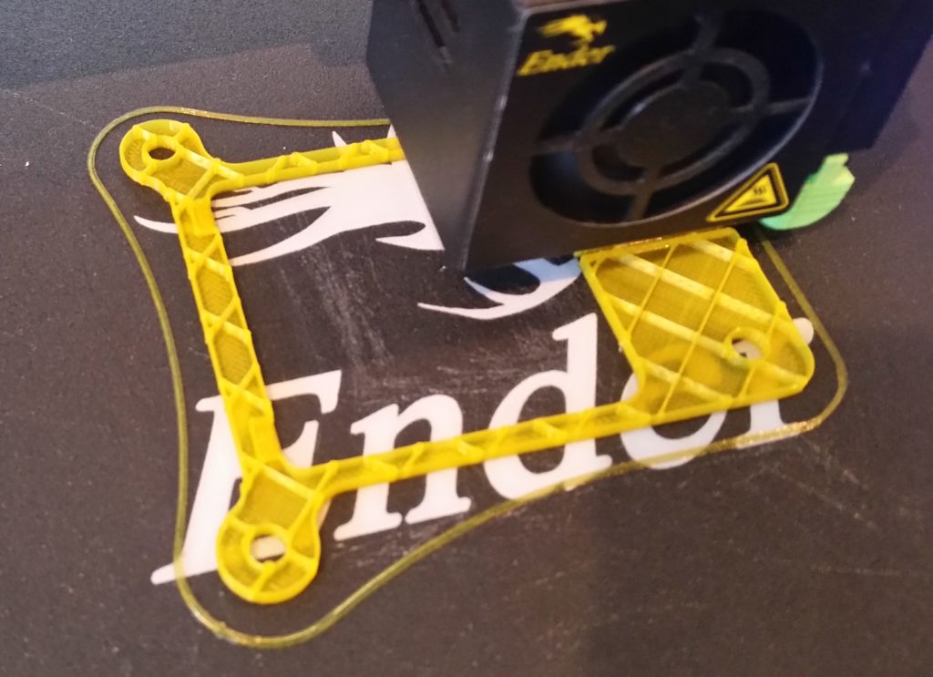
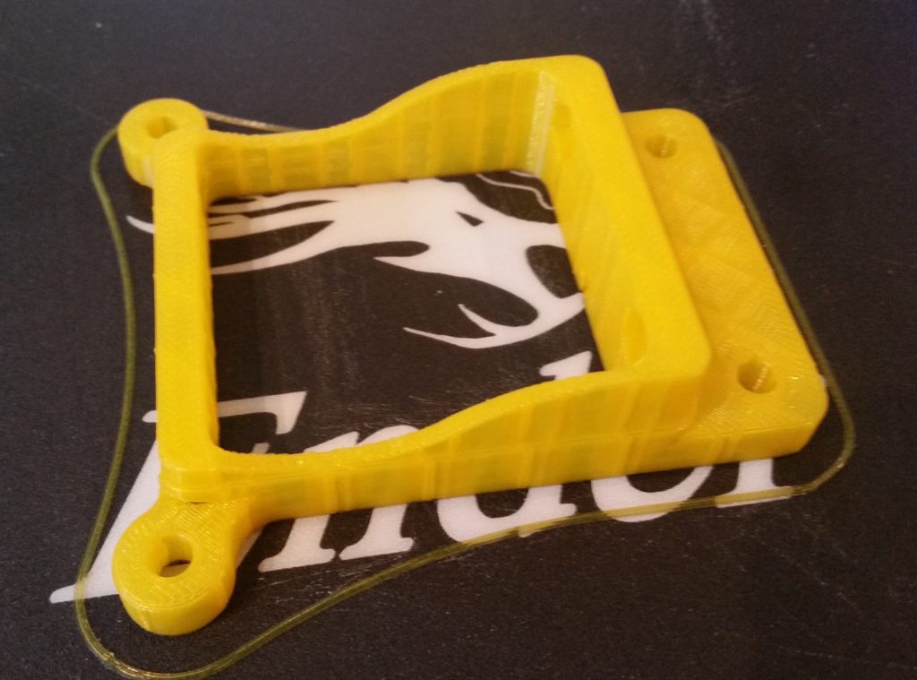
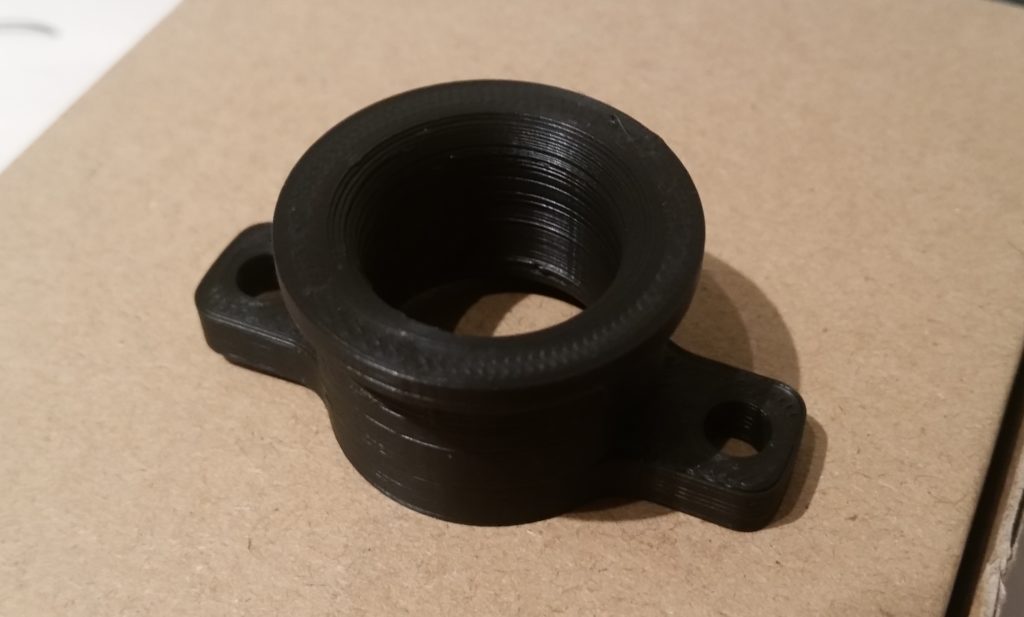
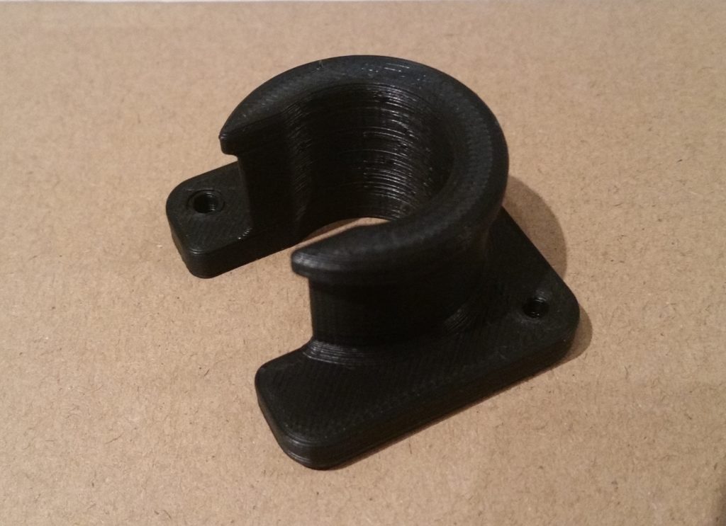
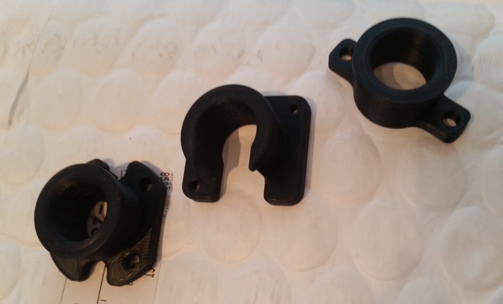
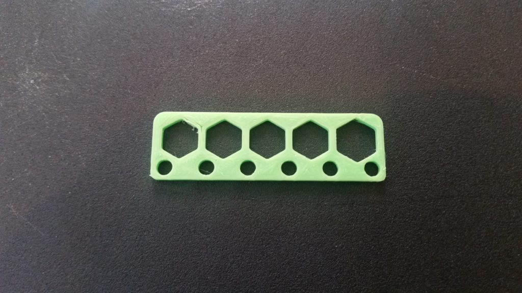
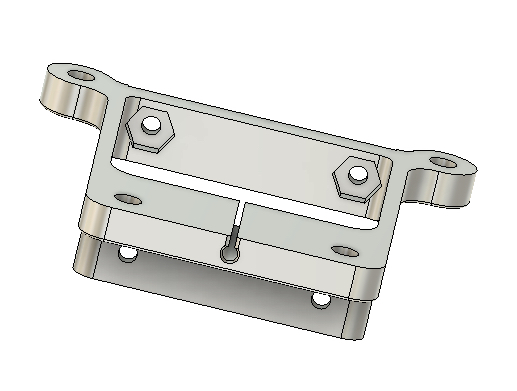
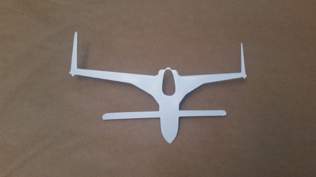
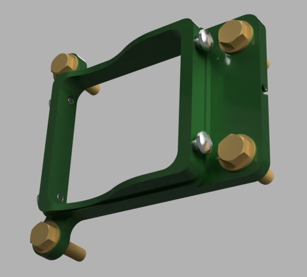
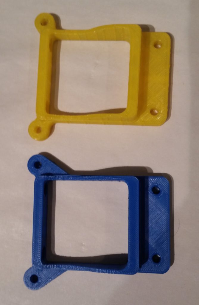
I started out today by 3D printing Version 2 of the starter contactor mount with the dozen or so minor tweaks that I did to improve fit and function.

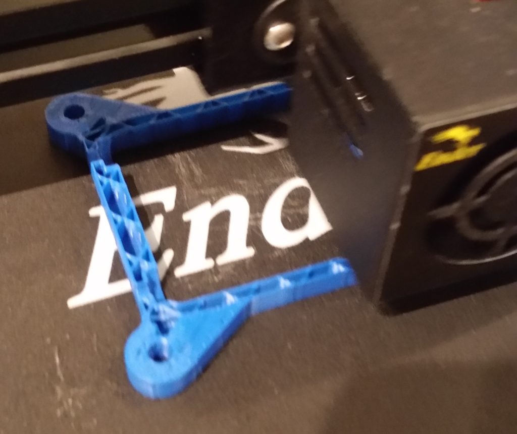
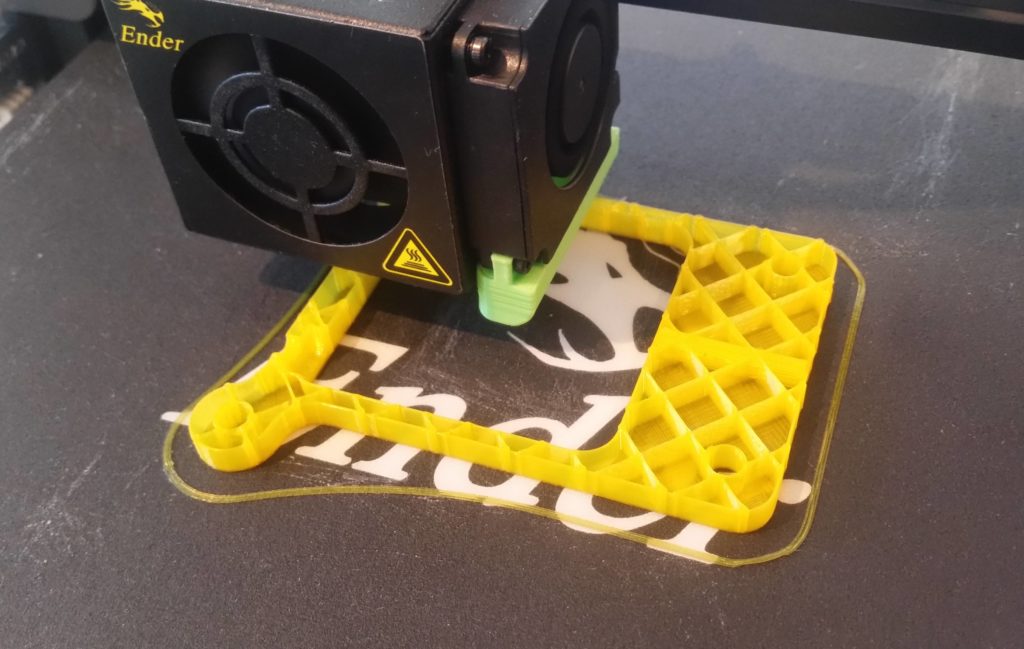
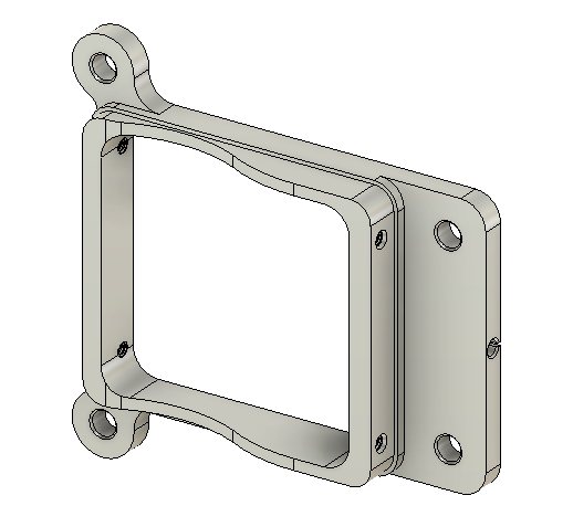
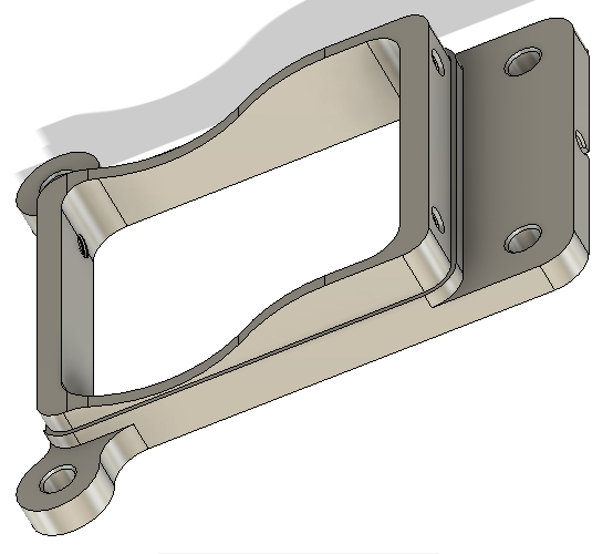
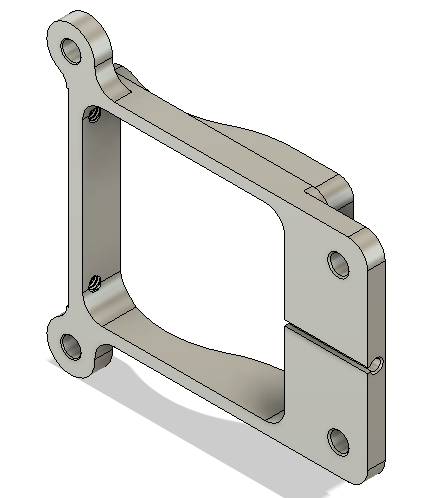
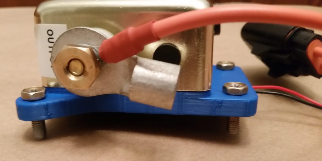
The most noticeable change between Version 1 and 2 is that I added a triangular fillet between the protruding bolt mount and the frame on each side to increase the overall strength of the mount, especially at the attach points.

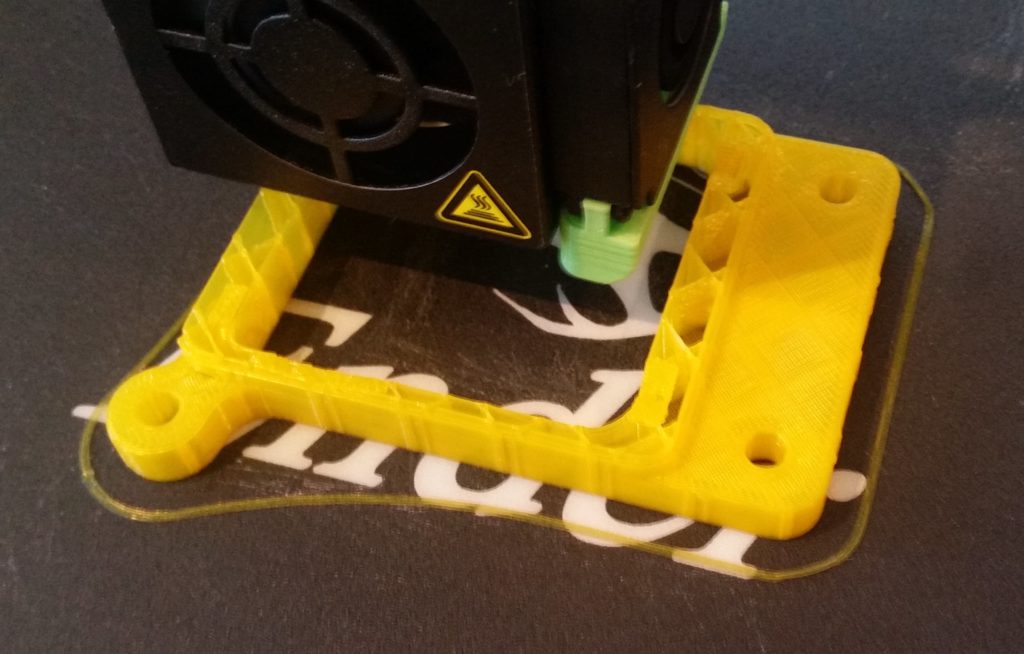
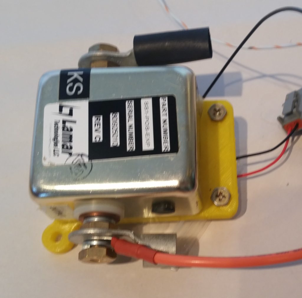
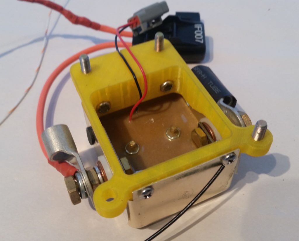
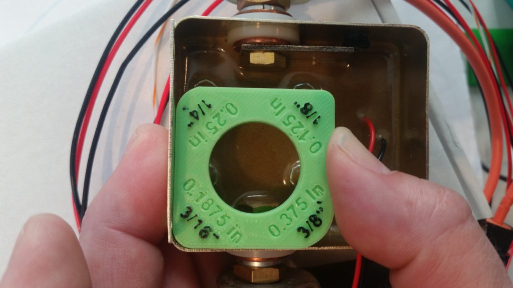
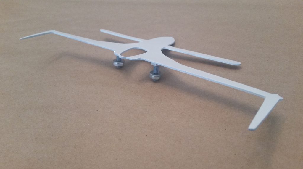
After the Version 2 mount finished 3D printing I then attached the starter contactor to it.  I have to say the fit to this Version 2 mount was noticeable better, with a lot less play –however minor it really was– between the contactor and mount surfaces.  

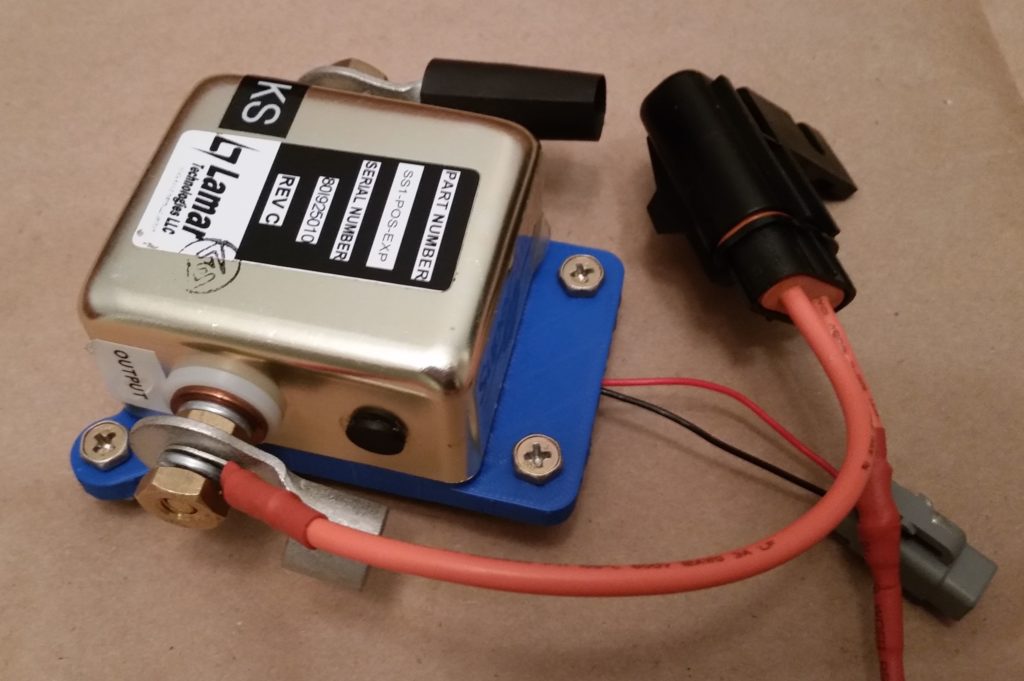
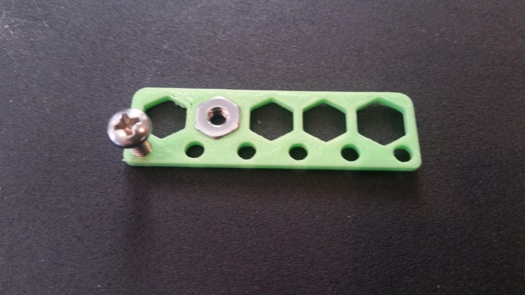
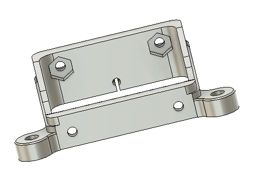
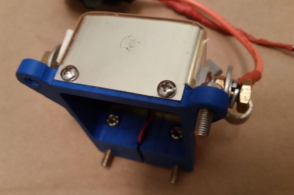
Also on this new version of the mount the 4 securing #6 nuts took a lot less effort to snap into their hexagonal embed depressions as well.

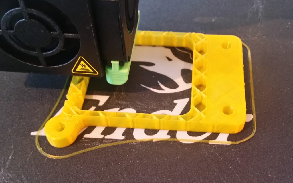
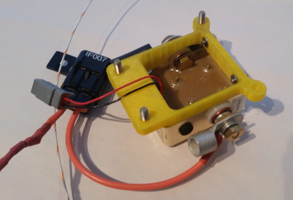
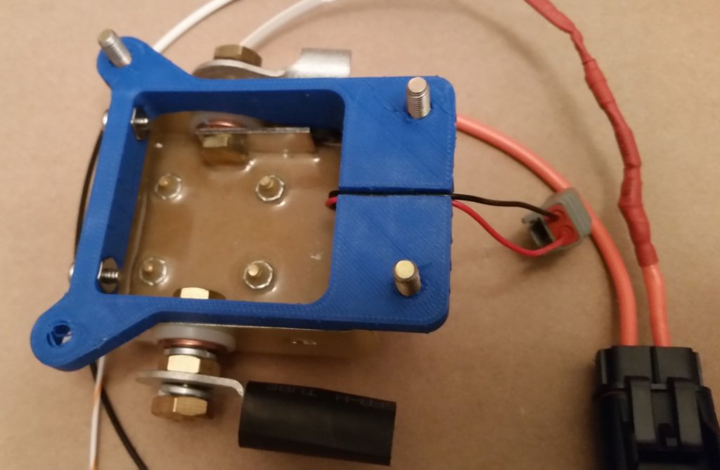
Moreover, I was actually able to get the small gauge control wires to fit into the slot on the underside of the mount.  To be fair though, I still ended up taking just a hair more off each side of the slot in the CAD drawing on what should be the final version of this starter contactor mount.  

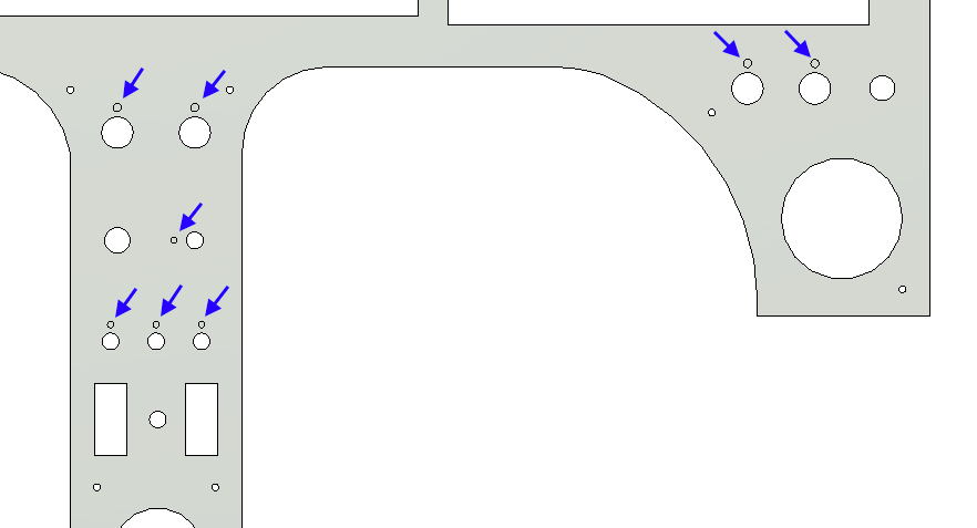
In addition, I added a significant fillet at each each of the wire channel to eliminate any type of corner chaffing or distress on these 2 small control wires (red & black).  I didn’t add these fillets in on the planned aluminum version of the mount since there’s no (reasonably easy) way to create them on the mill if this were milled out of a block of aluminum. However, since a 3D printer builds from the table up, versus cuts away material, I can easily add these in to be 3D printed as its depicted in the CAD drawing.

With Version 2 of the starter contactor mount completed and a success in fit, finish, and configuration, the next thing on the list is to simply see if it will fit in the battery compartment of my Long-EZ… which I’ll do when I’m down in North Carolina later this week.

Chapter 22 – Starter Contactor Mount

Today I started off by 3D printing Version 1 of the starter contactor mount.  I printed it with just enough plastic to hold a good shape and present the size as depicted in my CAD drawing.

Below is the finished 3D printout of my starter contactor mount.  Again, to be clear this print was made using the very common PLA plastic, which is not structural nor is it tolerant of moderately high heat.  Being a mockup, I don’t need to use the more structural types of plastic (ABS, PETG, etc.) right now just to figure out final part dimensions and configuration.

I then mounted the starter contactor to the freshly 3D printed mount.  The contactor fit fairly well, but there was definitely room for improvement (literally).

Here we have the underside of the starter contactor and mounting bracket.  

All in all, on this version I found about a dozen tweaks that needed to be made.  From adding just a few thou of clearance at the nut embed depressions, to making the wire channel for the small red & black control wires just a bit wider as well (thus the reason the black and red wires are not running through the 3D printed channel that lies between the two mounting bolts).

I will also note that since I converted a design originally for aluminum to be a 3D printed part, I decided that in Version 2 I will increase the size of the 2 round-shaped bolt attach points.

I also did a bit of tooling up for the Lathe CNC conversion project as well by 3D printing three mounting brackets that will be used to secure the accordion-type tubing that will help protect the cross-lathe running Z-axis ballscrew.

Tomorrow I plan on tweaking the starter contactor mount CAD drawing and then 3D print Version 2 of the mount.

Tooling Up: 3D Printer

It’s been a few days since I received my 3D printer, the Creality Ender 3 Pro, and instead of posting a gazillion pics of its assembly and initial 3D printed parts, I decided I would simply wrap all that up in a fairly short video:

You may have noted a distinct lack of Long-EZ build related prints in the video, since I wanted to highlight those pieces that I printed specifically for the Long-EZ build more in depth.  

Starting off, below are the 3D Printed interior corner radius gauges that I drew up in Fusion 360 CAD.

Then, to increase the radius dimensions’ visibility I highlighted them with a black Sharpie.

I then used the radius gauges to check the interior radius of the starter contactor corners. I started off with the 1/8″ side of the gauge, but as you can see it didn’t fit just right.

Moving along, the 3/16″ radius was pert near spot on.  Interestingly, when I checked the dimensions I had used in my Fusion 360 CAD drawing, I had correctly guessed that the corner radius was 3/16″.  Confirmed, and task completed!

I then printed out the #6 screw and nut tolerance guide.  I didn’t add labels to this printed piece because as I found out with the interior corner radius gauges above, labels add a considerable amount of time to the print.  

I then placed a quarter next to the gauge to add perspective to its actual size.

And then put the gauge to work as well to figure out the proper clearances for the starter contactor’s securing #6 screws and nuts.

As you can see, I’ve been quite busy 3D printing pieces, bits and parts for both the 3D printer itself and some aircraft related components.  

In short, this 3D printer performs great and appears that it will be a huge benefit in facilitating the completion of the Long-EZ project.

Super Secret Project

Yes, as I mentioned in my last post, I went back to work on my Super Secret Project after Marco left after his short visit a couple of days ago. Of course not before telling Marco that I was working on a Super Secret Project… which by its name denoted that I couldn’t let him know what it was!  Gotta have a little fun, right?!

Well, my Super Secret Project was simply that I ordered a 3D Printer and I was gathering as much info as possible on 3D printing before it arrived.

In prep for the delivery of my 3D Printer, I fired up the ‘ol Fusion 360 CAD software to convert my Starter Contactor mount from one that was designed to be machined out of aluminum to one more 3D printer plastic friendly (to be clear, I’m not using the common PLA plastic for the mount, but PETG for it’s strength and higher heat tolerance).  

The main modification to the Starter Contactor mount was to add #6 nut sized hex embed notches for each screw, clearly to allow each #6 nut to be embedded into the plastic as a screw hardpoint.

Here we have an interior shot of the forward set of #6 screw/nut embed notches.

And here is a shot of the aft set.

I also sketched up a set of interior corner radius gauges to confirm the corner radius’s of the Starter Contactor case.

Finally, since I knew there will need to be a tad bit of extra clearance for the embedded #6 nuts and the actual #6 screws themselves, I drew up a quick gauge for that as well.

I expect to get the 3D printer later today or tomorrow, so again I’m just trying to be as prepared as possible to hit the ground running when it arrives . . . and get some 3D printing knocked out!

Marco visits the shop!

Let’s start with some Tooling Up shall we?

I started off today with a delivery of my order I placed with Aircraft Spruce that included some of the final metal stock I need for the both the lathe and mill CNC conversions.

I then got a call from Marco, who was heading up to the DC area for some job stuff and wanted to drop by afterwards for a short few-hour visit.  

It’s always great of course to see Marco, and after I showed him my progress on the CNC conversion we went out for some fantastic Peruvian food while talking for hours on flying, building, machining, etc.

It’s even MORE especially nice when Marco comes bearing a gift, which in this case was a metal Long-EZ that he plasma cut and then painted.

As you can see here, the “main gear” is actually the mounting bolts that Marco welded into  place on the underside of the plate.  Great stuff and awesome work!  Thanks Marco!

And as Marco took off for home, I got back to work on my Super Secret Project!

Chapter 4/22 – Updating Panel

After all these years I finally made a decision to use 0.090″ 6061T6 aluminum to cut my instrument panel out of.  Using this specific aluminum offers 2 benefits over the 0.063″ 2024 aluminum that I had been planning on using for quite some time.

First off, plasma cutting 6061 is cleaner than 2024 since 6061 is better at rejecting heat (6061 can be welded, whereas 2024 cannot).  Also, a thicker panel has less tendency to warp during heat-producing operations such as plasma cutting.

Next, the 0.090″ thickness will allow hiding the panel switches’ anti-rotation keyway holes, which coincidentally need to be 0.063″ deep.  Below, the blue arrows denote 8 of the 10 anti-rotation keyways (on the panel backside) –which were once all through-panel holes– that were removed from the front face of the instrument panel once I thickened the panel from 0.063″ to 0.090″.

Below is a more “3D view” to better see the switch anti-rotation keyway holes at an angle, again, on the backside of the panel.

Meanwhile, over on the front side of the panel: no visible switch anti-rotation keyway holes!

Here is just a quick annotation of all the anti-rotation keyway holes that I was able to remove (hide) off the panel front by going with the thicker 0.090″ 6061 aluminum panel.

Once again, back to some CNC Tooling Up: Today I was able to install all the major Centroid Acorn CNC hardware components into the Lathe CNC Controller Box.  

I started off by installing the 24V/5V power supply into the back left corner of the box. With it situated as it is in the pic below, it will provide decent access to install/add/manipulate wires as needed.

[NOTE: The screw in the middle area on the floor of the controller box is for the X-axis’ 36V power supply that will get mounted on edge just like the current one installed].

I then focused on the component installs on the removable plastic tray.  First up was determining the location of the Acorn relay breakout board.  Critical in choosing a location for the relay breakout board is that the flat wire bundle that connects it to the Acorn main board must not be twisted in any way, but remain flat… as per a warning in the Acorn CNC manual.  

To achieve the non-twisted routing of the Acorn relay breakout board’s wire bundle to the Acorn main board, I utilized the opening in the plastic tray to run the wire bundle through and then above the Acorn main board by the gap created with the standoffs used in securing the main board to the underside of the plastic tray.

Here we have the Acorn main board installed on the underside of the CNC controller box’s plastic tray.  

If you look closely, you can see the wire bundle from the Relay Breakout Board attached to the main board at the very bottom of the main board– where the red wire is hanging off.

I have a 92mm x 92mm 5V cooling fan on order that I will install once it arrives.  Besides the fan (and associated vent), I have one more hole to drill that will use a grommet to protect the wires for the E-Stop switch and both Home/Limit switch wires.  Finally, I have one more board to install that will allow me to control the spindle speed and direction (primarily to facilitate tapping operations) and then I’ll be pretty much done with the planning, design and component install for the Lathe CNC Controller Box.

Chapter 4/22 – Panel Cut

In one of our conversations my buddy Marco asked if I had cut out the panel yet, so I sent I sent him this . . . Yep! (yuk-yuk) 

Of course this is the cardboard panel cutout… that I drew up in Fusion 360 CAD and then Marco precisely drew out for me on cardboard using his plasma cutting machine as a high-end plotter.

As a point of note, I’ve made a final decision to go with 0.090″ thick 6061T6 as my panel material.

Back to some CNC Tooling Up: To help organize some of the myriad of parts I have on hand, I decided what better way to keep track of them other than simply install them?!

So I took a few hours to do some final design work, then some drilling and Dremel Tool cutting to add some of the loose components to my Lathe CNC Enclosure (AKA “Tool Box”).

I started with with each end, and below is the left end as facing the front of the tool box.  

From the lower left hand corner, going clockwise, we have the power plug compression mount, a fuse holder with 10 A fuse, the spindle encoder cable compression mount, the lighted ON/OFF switch, and the CAT5e port.

So far on the right side I was only able to get the X-axis and Z-axis stepper motor compression mounts installed.

Towards the middle of the right end of the Lathe CNC Control Enclosure will be a large cooling fan, and also another wire entry port(s) for the E-Stop Switch and the Home/Limit switches wires.

Back upstairs –under some very harsh lighting– I grabbed a couple shots of the interior of the box where I drilled the mounting holes to vertically mount both 36V power supplies and both Hybrid Stepper Motor Drives (blue components).

Tomorrow I plan on drilling one more set of holes on the floor of the Lathe CNC enclosure to mount the Centroid Acorn 24V/5V power supply, then I’ll work a bit mounting the Acorn main board and relay bank on the upper removable shelf of the Lathe CNC enclosure.

Tooling Up: Spinning CNC motors

Before I pack up and haul my new CNC components down to NC, I needed to do an operational function test on each part to ensure it works.  For each closed-loop stepper motor setup this includes the motor itself, the drive (blue units) and the associated power supply.

Since one of my power supplies was back ordered, I only have 2 on hand to test out 3 motors.  I could have connected two motor setups onto one power supply, but I decided to keep it simple with one power supply to one drive and one stepper motor.

The closed-loop stepper motors I have on hand is an 8.5 Newton Meter (Nm) Nema 34 (mounting size) for the mill’s Z axis, a 4.5 Nm Nema 34 for the mill’s X axis, and a 3.0 Nm Nema 23 for the lathe’s Z axis.  I also have a 4.5 Nm Nema 34 for the mill’s Y axis on the way.

I started my ops test with the 8.5 Nm Nema 34 and 3 Nm Nema 23 stepper motors.  Prior to the actual ops check I connected up a data cable to the respective motor drives and changed the drive alarm circuit parameter from Normally Open (NO) to Normally Closed (NC).  This is rather important in identifying any drive fault in that a NO circuit would not indicate if the actual circuit was, say, cut.  Conversely, if a NC alarm circuit is damaged or cut it will result in an alarm…. clearly better (IMO) to have a NC alarm circuit.

Since this was my first go at real-world spinning of the stepper motors, it required a 2-hour period of research and digging in the manuals to educate myself after I got power to the motors to actually allow the Acorn CNC controller to control the motors.

Here’s a ~25 min video showing my efforts:

I still have the 4.5 Nm motor to test, but I think all the above is enough excitement for one evening!

Chapter 22 – Contactor Mount

Since arriving back home from my latest NC/Virginia Beach trip I’ve been in a mad dash to finish up some of the tasks I started while on my journey.

One such task was to finish sketching out the mounting base for my Solid State Starter Contactor –the Lamar Superswitch– that I’ll be using in my Long-EZ.  

If you’re curious why I’m using this rather esoteric component, it’s because it has no moving parts to weld to each other or simply wear out (as mechanical contactors tend to do) and, more importantly, it weighs in at around 1/3rd of a pound vs. its hefty 1-pound mechanical cousins.

[NOTE: These are no longer available nor sold through Aircraft Spruce]

The one slight downside to the Lamar Superswitch (which, as an FYI aside was used extensively by Lancair Aircraft) is that it is open in the back to the innards which is essentially a bunch of potting material and the internal side of the 2 big cable studs.  With a flange with 2 small holes, there’s not a convenient way to mount this contactor without making up some type of lightweight aluminum mounting bracket, which I’ve done here.

So here’s my spec’d and designed Starter Contactor mounting bracket that will secure the Lamar Superswitch onto the sidewall of my battery compartment.

The version above actually had 4-40 screw holes as one of my tasks this morning was to determine the size of the two screw mounting holes located on the contactor’s aft/lower side (bottom/back <unseen> in the pic of the unit at top).

Determining that the mounting screws need to be 6-32 screws, I then reset the diameter and threads for all the mounting screws in the mounting base to this correct size.  I also moved the holes a bit farther up.  These updates are shown in the CAD sketches below.

The original mounting holes for the contactor unit are to the left in all the depictions of the mounting base shown here.  The new mounting holes, which I’ll have to drill into the contactor housing (top edge in pic at top), are the ones located to the right in all these depictions. 

Below is the back side of the Starter Contactor mounting base that is actually shown in the 180° reverse position to how it will be mounted in the battery compartment of the plane.  

The cylindrical channel with the slot is for 2 hardwired small diameter red & black control wires (behind, right and top in pic at top) that will be channeled through the mounting bracket to then safely exit out of the unit/mounting bracket combo for subsequent connection into the electrical system.

Of course I’m glad to get this component lined off of my CAD sketch to-do list, but it of course wouldn’t be complete without a fancy rendered version of it!  I chose green not because it will end up green, but just to shake things up a bit.  

Again, the silver-colored Phillips-head screws are #6 sized screws, while the Cadmium colored mounting bolts are #10 (AN3) sized.  I may go down a size to #8 on the mounting bolts, but I’m still assessing that option.

Regardless, I’m calling the CAD drawing and design for the Starter Contactor mounting bracket complete!

Chapter 4/22 – Panel Cutout

After departing NC on this last trip to clear out my #3 storage unit and consolidate nearly all the airplane build stuff in the hangar, I headed up to Virginia Beach to spend a couple of days with Marco and Gina.

While at Marco’s, I updated my Instrument Panel CAD diagram with all the dimensions I had taken off the actual panel while down in NC.  With Marco’s help, I then shared the CAD file to a shared online folder and he was then able to convert it into CAM to be drawn out on his plasma cutting table with a Sharpie onto cardboard.  

This may seem like some underutilization of a fairly expensive plasma cutter to merely use it as a plotter, but not only did it test & confirm some limit capabilities of Marco’s plasma cutting table (better than we initially thought), but obviously it will allow me to cut out the cardboard panel, test it in the actual airplane, and then make any required tweaks if need be before we do an actual plasma cutout of the panel with actual expensive aluminum.

In fact, the pics of the crazy bearded guy below (me!) is with plotted panel version #1, which afterwards I realized that I had forgotten to update some dimensions I had gathered relating to the panel’s upper corner longeron notches . . . 

Although I’d like to say it was fairly easy to update the CAD file to redraw the dimensions on the panel longeron notches –and subsequently the top panel contour– it actually did take a bit of drama-filled machinations to get it done.  But, with Marco’s help I learned a few new tricks regarding Fusion 360 and was able to update the panel drawing to the correct dimensions.

We then embarked on plotting out Instrument Panel version #2 on Marco’s plasma cutter with no hiccups.

In fact, I took a short video of the last little bit of the panel plotting effort on the Plasma Cutting table.  We didn’t film the entire event since to draw the separate circles and rectangles in the panel we had to lift the Sharpie up slightly in its holder (which Marco cleverly designed and 3D printed) after each drawn component to allow the assembly to relocate to the new spot that the next component would be drawn, then slide the Sharpie down in contact with the cardboard.  

This pen lift/drop cycle is shown in the video, as is the entire drawing of the Instrument Panel perimeter.

After the instrument panel plotting was done on Marco’s plasma cutting table, I then labeled the components on the cardboard to grab this shot here.  Most of the larger component holes will get cut out, which I’ll show in a subsequent blog post.

I’m extremely pleased with how the cardboard panel mockup came out, and am excited about dialing in the panel CAD drawing to enable Marco and I to plasma cut my panel out of a piece of aluminum.  I will say that Marco and I (and a few others) are discussing the pros and cons of 2024 vs 6061 and what thickness the panel should be (0.063″ to 0.090″).