Chapter 22 – More Brackets & RCU

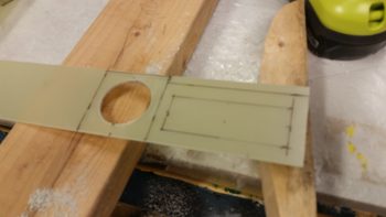
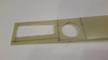
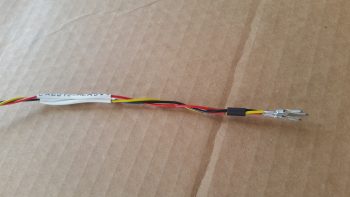
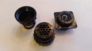
I started off today by razor trimming the bracket for the Throttle handle electrical cable P4 AMP CPC connector.

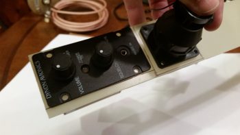
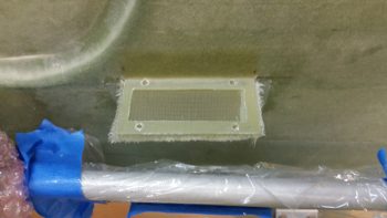
I did the same thing for the right armrest-mounted Dynon intercom bracket that I just glassed in using 2 plies of BID.  On both of these brackets I was able to knife trim them right at their curing sweet spot, so the glass was definitely more on the cured side, but still just a tad pliable . . .  so it cut well.

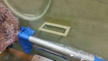
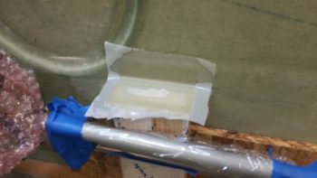
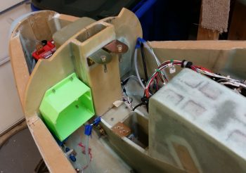
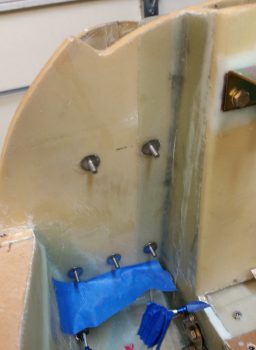
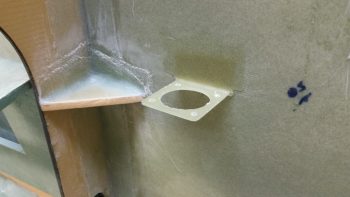
I then laid up 2 plies of BID on the bottom side of the Throttle handle electrical cable connector bracket.  I used a small flox fillet in the corner and peel plied the glass junction with the sidewall.

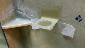
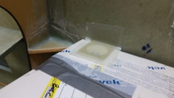
I did pretty much exactly the same thing on the Dynon intercom bracket only for a bit more strength I used 3 plies of glass on the bottom side.

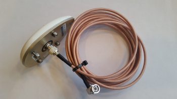
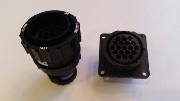
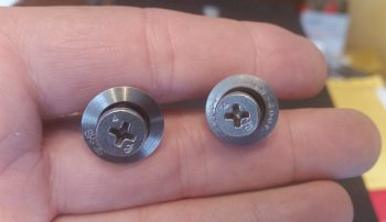
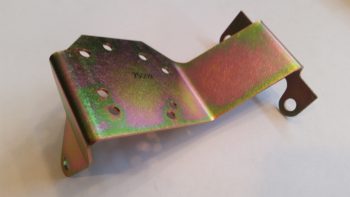
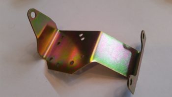
Speaking of brackets, I just received this today so I thought I’d throw it on the blog.  This is the fuel injection spider mounting tab that goes on the top centerline of the engine.  Yet just another item that will go on the shelf for the time being.

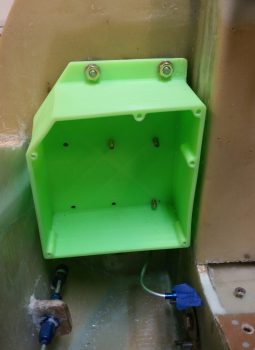
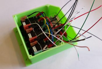
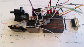
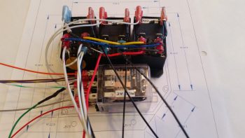
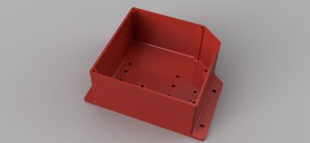
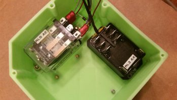
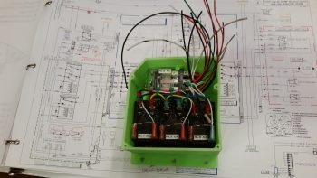
With my bracket glass curing, I started in on mounting the 4 beefy relays into the gear Relay Control Unit (RCU) box . . . fitting name, eh?!  The first relay to go in was the clear cased 3 pole Auto Extension (AE) relay, RL000.  It handles the actual engagement of the gear Auto Extension feature and also is a pass-thru for all the major electrons running the gear up or down.

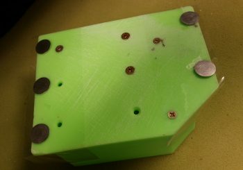
I ordered this relay specifically with bottom mounting tabs, with the corner of the left tab needed trimmed diagonally just a hair for it to fit properly.   It mounts with a 4-40 screw on each side, each coming in externally from the back.  All the mounting screws coming in from the back side are countersunk to allow the back surface of the box to remain flat, which facilitates ease of mounting the box to the aft side of the Napster bulkhead.

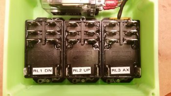
Next relay up to get mounted inside the box was RL003, or the AX relay.  This relay is the one I added back into the mix that charges the small 1.2A backup battery that was provided in Jack Wilhelmson’s original design.  Relay #3 takes control of the system in case of a power emergency to drop the gear down using the 1.2A backup battery for power.  In Marc Zeitlin’s new gear wiring design he doesn’t use this relay since his system incorporates a manual (ratchet) drive for emergency gear extension.

Finally, as for relay #3, I mounted this guy first since it has a unique feature that needed to be dealt with that the other two black relays don’t: down along the top side of the relay is the RXEF-250 wafer style fuse soldered into place that’s used during backup battery charging.  Getting under this fuse to install the K1000-6 nutplate would have been a lot more difficult if I couldn’t get in from the side (where the other two relays sit) to mount the nutplate.  After I mounted this relay, I put some double sided foam sticky tape underneath the wafer style fuse to keep it mounted to the front of the relay for anti-vibration.  I also tipped the box right side up and glopped some E6000 adhesive (yep, the stinky stuff) onto each edge of the fuse to keep it secure to the relay, banned the box outside on the deck for a few hours while it cured and I took off to run some errands.

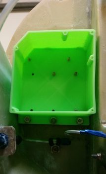
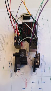
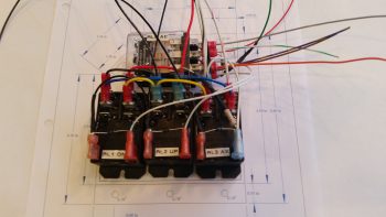
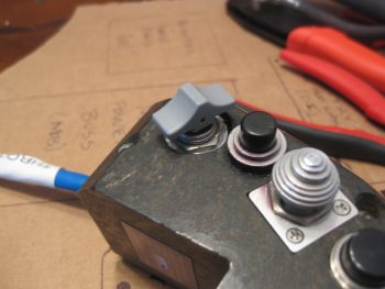
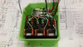
Upon returning from my errands (which included buying parts for the flexible sander Nick Ugolini describes how to build on his blog) I installed the last two relays: RL001 & RL002 [Note: Simply for space I truncated the relay IDs and labeled them on the actual relays with RL0, RL1 … etc.).  As you can see, these two relays simply control gear up and gear down, respectively.  All went well except for the life of me I couldn’t find a 6th K1000-6 nutplate to use on the top side flange of RL002.  After searching for a good while, and simply not finding the pack of 23 I show having on hand (simply maddening!), in order to get this thing wired up tonight I improvised, adapted and overcame by using an aluminum binder stud, cutting off the top and then quickly Dremeling a not-so-pretty slot for a bladed screwdriver.  I doused it with a good measure of blue Loctite and in it went… Voila!

Here’s another shot of my mounting improvisation . . .

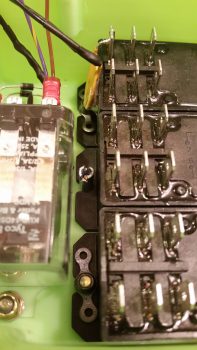
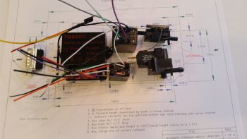
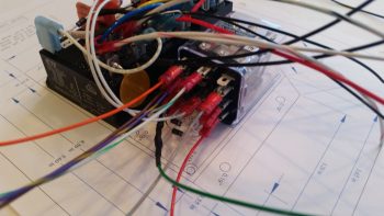
Over the next couple of hours I confirmed & verified the wiring in this box matched exactly what was on the diagram.  Having had to pull all the terminals off their posts, I used a pair of channel lock pliers to compress the terminals just a bit to ensure their clamping pressure was nice and tight.  I then slowly replaced all the terminated wiring back onto the relay posts, performing a continuity check as each set of wires went back in.  After all the wires were back in place, I zip-tied them into place to ensure no wires would be vibrating and wreaking some future electrical havoc by gnawing through a neighboring wire, etc.

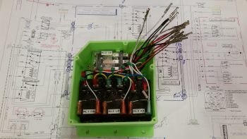
Here’s just a closer shot of the internal RCU box wiring . . .

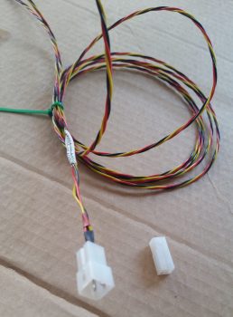
I then cut & terminated all the wires with AMP CPC sockets.  Again, as I finished each wire I performed a continuity check to ensure all was electrical good on that wire circuit from source to connector.

With all the RCU box wiring set to be terminated into the AMP CPC connector, I called it a night.  I may have actually done a bit more but it was quite late and I was collaborating online with Marco (who was in Hawaii for work!) on the specs for the AEM box.


Chapter 22 – RCU Box & Brackets

I didn’t get the intermediate steps documented since I’ve been out & about this weekend with friends.  Here is the final result of the Clickbond mounting for the Nose Gear RCU box.  Again, I used 3 plies of BID along the top row (2 Clickbonds) . . .

. . . and 3 plies of BID along the bottom row (3 Clickbonds).  After curing, I pulled the peel ply and cleaned up the goobers.  Thus, the RCU box is officially mounted.

A little sideline tasker I completed was to drill and flox in place this Adel clamp for the Throttle electronics cable that terminates into the P4 Connector.

After pre-drilling the 4 screw holes and the 8 holes for the K1000-6 nutplates, I then did a final trim & sanding on the Dynon Intercom bracket.  I determined where its position needed to be and marked the sidewall.  I then 5-min glued the intercom bracket to the sidewall.

I then laid up 2 plies of BID (pre-pregged of course!) on the top side of the intercom bracket, and peel plied it.

I pretty much followed the same steps for the Throttle handle electronics cable P4 connector bracket just forward of the instrument panel on the left side.  After 5-min glueing it to the wall, I laid up 2-plies of BID and peel plied it.

These tasks above are all on a list of 10 electrically-related items that I want to have finished before I move on to the wheel pants.  Once these brackets and the RCU box wiring are completed, I’ll be down to about a half-dozen items on the list.


Chapter 22 – Mounting Gear RCU box

Today I received the Nose Gear RCU box in the mail from Marco.  He did a great job and the relays fit perfectly!  A little too perfectly actually . . . The holes are aligned exactly as I designed them in CAD, except I put them in a little too close to the end wall of each relay so that I won’t be able to fit a normal aviation/MIL-SPEC nut on the screw.

After thinking about this issue a bit I realized that the answer was fairly simple: nutplates. Nutplates are narrow enough that they’ll fit and even though a bit higher cost solution than normal AN nuts, they’ll definitely do the trick.

With the relay mounting issue out of the way, I prepped the box to be mounted with 5 Clickbonds.  The mounting holes’ diameter were just slightly narrower than designed, so  I spent a few minutes drilling those out to size.  I then taped the back side of the box with clear packing tape.  After roughing up the back sides of the Clickbonds with sandpaper, I cleaned them with Acetone.  I then mounted them in the box, whipped up some 5-min glue and put a good dab on each Clickbond face.

I then mounted the box on the aft side of the Napster bulkhead aligned with some position marks that I had previously made.  I held the box in position for a little over 5 minutes to let the 5-minute glue cure.

With the 5 Clickbonds attached to the aft face of Napster I pulled the RCU box off of the bulkhead.  The Clickbonds set well and the attachments were solid.  I cleaned up some of the 5-min glue gunk and left the Clickbonds alone to fully cure.

While the Clickbonds cured, I measured out the dimensions I would need for the BID tapes for the top and bottom row of Clickbonds.  I wanted at least a good inch from each Clickbond stud to hold it securely in place.  I cut 3 plies of BID 2″ high and with a slight angle for the outboard side of the upper row, for a total of two sets of 3-ply BID.  I then configured the BID plies in plastic for pre-preg setups and called it a night.

Chapter 22 – March Madness Brackets!

Well, My March Madness brackets!

Today I started working on the brackets for both the P4 throttle connector bracket and the Intercom bracket.  As for the Intercom bracket, I decided that I’ll most likely make the right pilot armrest removable to gain access to intercom wiring.  So the intercom mounted in the bracket will remain on the sidewall, allowing the armrest to be pulled away from it.

I started off by determining the dimensions of each bracket, and then marked up a 1/16″ piece of G10 with these dimensions.  I then drilled the 1.5″ hole for the Throttle P4 AMP CPC connector.

I then cut the rectangular hole for Dynon Intercom.

And then test fitted both the Intercom and the P4 connector, with both fitting just fine.

After prepping the holes I took the evening off to go to dinner.

Chapter 22 – Cables, cables, cables

Today’s post is just a quick update showing some cable builds.

First off is the 3-wire braided cable for the Nose Gear Auto Extend laser altimeter.  These three 22AWG wires will provide power, ground and signal path from the laser altimeter into the Auto Extend Module (AEM).

After terminating the wire ends with mini-Molex pins (above) I then inserted the pins into a connector body.

I also soldered 2x 22AWG wires to a 9-pin DSub connector to make up the connector that all the panel components that require an external dimming control will tie into.  The black wire with the DSub pin is a ground wire to the avionics ground bus (G5) for the dimmer module shown at the bottom of the pic below.

Finally, although I didn’t make this cable, I thought I’d show it just to hint at a bit of progress on the GPS navigator install front.  I ordered a 12′ RG400 cable with a TNC connector on one end (mounted to the GPS antenna in below pic) and a 90° BNC connector on the other end.  Since I only need around 6′ for the GPS antenna, I’ll use about half of the RG400 cable and the BNC connector somewhere else.

That’s all for now folks!


Chapter 22 – Wiring AEM components

Today I finished wiring all the components of the Nose Gear Auto Extension Module (AEM) as far as I could without having the physical box in hand.  As I’ve mentioned before, the AEM is simply an upgraded replacement of Jack Wilhelmson’s Nose Gear AEX system that utilizes Marc Zeitlin’s design to incorporate a few more parameters into the Auto Extension system to pretty much eliminate annoying false-positive situations and ensure that really the only time the AEX will deploy the gear is on final approach when you actually forgot to put the gear down.  To make the magic work, Marc added another airspeed switch (for a total of two), a throttle mounted “microswitch,” and a laser altimeter.

I decided to cram all this new stuff into a box approximately the same size as the original AEX box.  Since Marco is 3D printing this one as well, it will have holes ready to go for mounting the internal components and some external mounting flanges for attaching the box to the forward side of F22 with Clickbonds.

The laser altimeter operates on 5 Volts, so it requires a 12V-5V converter.  However unlike Marc Z. I chose to mount the converter up front versus the way he did right next to the laser altimeter (which is on the belly near the main gear).  There is no right or wrong here regarding the location of the voltage converter, I just simply wanted to drive the weight forward and also hide the converter away in the AEX box.

In between the voltage converter (right, below) and the airspeed switches (left, below) are two relays.  These relays are unique to my specific system since these are the ones I needed to wire into the mix if I wanted to continue to use my throttle-mounted toggle switch to control the nose gear up/off/dn.  These relays are fairly small and light, although robust, so the weight penalty is negligible.

Finally, in each pic I show the 15-pin DSub connector.  In the very top pic, and the one below, you can make out the black bar that depicts the hole for this DSub connector on the actual-sized box CAD diagram lying below the components

As with my RCU components, the only thing left to do with these are to physically mount them into the box and then cut & terminate the wires with DSub pins.  I do have a few minor tasks that I can complete for the final prep of this system before I have boxes in hand and am ready to install.


Chapter 22 – Gear RCU Wiring

Today I finished wiring all that I could on the Nose Gear Relay Control Unit (RCU).  My first task of course was to trim the lengths of the cross connect wires to the outboard relays (#1 & #3).  I then re-terminated the wires with new red FASTON terminals and double checked that all was good with those.

I then started cross-connecting wires from the 3 lower relays (black) to the top AEX relay (clear).  One of the big challenges, which I think is a bit analogous to solving a puzzle, is to take the logical wiring diagram on paper and determine how the wires and components actually hook together in real life.

What looks like a long wire on the page can of course be no wire and simply a lead to a diode or resistor.  Such is the case with the RXEF250 Minifuse that looks like a brown wafer overhanging along the top side of relay #3.  Although on the diagram this shows up in the middle of wire run, in fact this Minifuse IS the wire run.  The diodes at the bottom of the relay connections in the pic below is also pretty much the same way.  On the diagram it looks like 3 diodes suspended mid-point in wire runs, when again they are the wire runs, all starting out at the AEX relay coil’s negative post.  Out of 3 diodes hooked to the coil post, only one them is physical attached to a wire, while the flyback diode is terminated with the positive power wire, and one is simply a loner heading off by itself to a Common terminal.

The wires going every which a way again will get corralled, secured and terminated into the 19-pin AMP CPC connector.

Speaking of connector, here is the AMP CPC connector for the gear RCU.

And a shot of the aft side of each connector half.

Besides physically mounting the relays, double checking the wire terminations & cross connects are correct and the terminals are attached tightly, the only thing left to do is to cut the wires to length and terminate the ends to fit into the connector.  Thus, on to wiring the AEM!


Chapter 22 – Gear Relay Control Unit

Over the past couple of days I’ve been designing what I have come to term the Relay Control Unit (RCU) box in CAD  [prior to this multi-day endeavor I spent a day and a half rewriting & reconfiguring John York’s CSA article on installing FeatherLite’s strake & strake leading edge kit specific to my build, and adding in all my past strake construction notes from Mike Beasley, Bernie Siu, Wayne Hicks, Dave Berenholtz … just to name a few].

With the incorporation of Marc Zeitlin’s new wiring for the nose gear Auto Extension System (AEX), which is essentially a redesign of Jack Wilhelmson’s entire electrical scheme for the nose gear, I wanted to get this new system as organized and compartmentalized as possible.  In short, I wanted the rats’ nest of wires gone and out of my nose compartment.

Now, the 3 main components making up my new electric nose gear system is still Jack’s electric nose gear actuator at it’s core, with the actuator motor and limit switches all tucked away under the NG30 cover.  The wiring exits the NG30 cover via a 14-pin AMP CPC connector and heads in two directions: 1) the new Relay Control Unit (RCU) that will reside on the left, aft side of the Napster bulkhead, and 2) the new Auto Extension Module (AEM) which is simply a replacement unit for Jack’s AEX box.  The AEM will sit in the same spot on the front CL of F22 in the top, aft notch in the NG30 cover.  The RCU will tie into the system via a 19-pin AMP CPC connector while the AEM will be connected via a 15-pin DSub connector.  Beside the larger backup battery and laser altimeter, there are minor few connections to the Triparagon, P4 Throttle Connector, and panel switches.  But for the most part, the lion’s share of the actual nose gear electrical system is contained within 3 major components: NG30, RCU & AEM.

I was drawing up a version of the box I wanted in my antiquated TurboCad system, when in a discussion with Marco he graciously offered to 3D print the boxes for me (maybe not quite understanding that my CAD kung fu wasn’t up to par with his!).  He had to redraw my neanderthal CAD drawings into Fusion360 but in the end came up with the awesome box rendering you see below (note: the angled corner is the top left box corner and is specifically shaped to allow it to fit with the curvature of the Long-EZ’s nose at its install point).

After some further discussion we came up with the lid design that will also be the attach point for the AMP CPC connector, since –YES– space is tight!

After confirming the myriad of little details on this box, Marco pulled the trigger and made our RCU box collaboration a reality.  Pretty cool, eh?!

With the RCU box design complete and construction underway, I then got to work on designing the AEM box.


Chapter 23 – The Skybolt of tomorrow…!

After another quick consult with Nick Ugolini, and after finally getting to the end of the proverbial research road on my Camloc/Skybolt solution (based on Nick’s fastener test) I had a Skybolt order sitting on my computer screen ready to go.  I wasn’t planning on buying these parts this month but since I had just spent over an hour performing some online price comparisons, and these were the lowest price I could find, I decided to not keep this in the queue any longer and pulled the trigger.

So, as with most everything on this build, besides the inevitable nickel & dime onesy-twosey pieces that will crop up and need bought, this purchase does it for my Camloc/Skybolt 1/4-turn fastener system.  This will allow me to virtually (but not completely) go Camloc on my cowlings, RAM air/hell hole cover, internal cockpit hatch covers, etc.

Concurrent to my Skybolt research and order trigger pulling, as I was watching Mike Beasley’s progress on his baggage pod installation, with the help of the ubiquitous baggage pod install master, Steve Beert, my curiosity around some particulars of the baggage pod installation got the best of me.  So late last night I pulled out my notes and ended up back on James Redmon’s Berkut13 site to see what he had to say about it.

I knew that if I wanted to use Camlocs on my baggage pods that I needed to use the removable grommet 4002-NS vs the SK-O18S grommet that is held in place with a snap ring.  If these numbers are new to you, welcome to the club!  As with so many components on these airplanes there are literally hundreds, if not thousands, of possible combinations.  Thus, I’m very thankful that Nick Ugolini documented his Camloc test.

Moreover, you may note that the the face of these grommets below look a bit different (to be clear: the grommet is the flange looking deal while the stud is the “screw”).  The one on the left is the non-removable (without tools) Skybolt SK-O18S, which I’ll be using for the majority of my Camloc installations.  The Camloc 4002-NS grommet on the right is meant to come out when the Camloc is unfastened and is used in places like the aft edges of the cowlings and on the baggage pods.

This view below clearly shows the difference between the SK-O18S on the left (secured to the cowling with a snap ring) and the removable 4002-NS on the left (for aft top/bottom cowling securing and baggage pods).

In addition, I discovered a nice surprise while re-reading stuff about installing the baggage pods on James Redmon’s Berkut13 site: he mentioned that Gary Hunter provided all the BID tapes required to mount these pods to your Long-EZ!  What?!  So I went digging in the box that I’ve had for a few years now and sure enough at the bottom was a box with the instructions in there and a bunch of MARKED bags with the BID required to mount the baggage pods . . . Now, how cool is that!!!  Who knew?!  ha!

One final point.  As I was reading through the how-to manuals & notes on installing the baggage pods, I discovered –the day after I got my Skybolt order!– that I needed one more of the -7 studs that I of course don’t have on hand.  See?!  I told you!  Build an airplane if you love never-ending goose chases… ha!


Chapter 22 – Electrons vs. Paper

Well, as I pointed out, between the holiday stuff, the football, and more importantly, this nasty cold I’m fighting, I have abided by my previous statement that the build would slow down quite a bit.

I did finally receive a pack of 1/16″ roll pins that I ordered, so I was able to mount my gray finger grip back onto the landing brake switch post (permanently).  Last year I had to drill out the original roll pin in order to get the finger grip off to then allow me to remove the switch from the throttle handle housing.  In fact, the hole that is now visible on the side (top) of the switch grip wasn’t there when I started last year and was created as a result of my drilling endeavors.  Presently, I put some E6000 on the bottom side of the switch to help seal up the roll pin hole.

Barring any other adventures, this does it for the completion of my throttle handle switch installation, wiring & prep.  Over the next few days, when I start feeling a LOT better, I’ll drill a hole or two in the lower left area of the instrument panel bulkhead to mount some Adel clamps for use to secure the throttle handle cable (and whatever other wiring needs secured).

Air Brake Toggle Switch Finger Grip

The remainder of my work over the past couple of days has been around finalizing the electrical system push. For one, I started compiling a list of even more electrical system components I’ll need for the future (shielded wiring, consumables, etc.).  I also printed out a couple of batches (~12) of heat shrink wire labels and attached some of those.

One main thing I’ve been doing, since I’m really not feeling up-to-snuff, is updating my electrical diagrams.  You can imagine there is simply a myriad of data that needs to be annotated (in digital form, vs. my own chicken scratches!) on these diagrams: wire colors, wire sizes, wire labels –these change a lot with the addition of connectors– circuit changes, etc.  I would say that it’s not uncommon for me to have anywhere from a dozen to 50 data points on each diagram that requires updating, which in and of itself isn’t necessarily or overly difficult.  However, the crosschecking (or consolidating) of ground points, bus tab positions (again, or piggybacking) –and making the decisions on those as well– is what eats up a good bit of time.  And of course there’s the oft required research that may accompany any such decision.

In addition, I’ve done (or simply documented) major circuit design revisions, mainly the items that are controlled via the airspeed switches and/or ancillary relays.  I also did a major overhaul of my panel dimmer and cockpit lighting & dimming circuit design as well. As a point of reference, I haven’t touched this particular wiring diagram since June 2014, so it definitely needed some attention.

I’m about 2/3rds through the diagrams and don’t have that many more to go.  Once I start feeling better, with my electrical system documentation updated, I’ll be ready to start back on some real work . . . like perhaps some wheel pants.  I will note that the wheel pants are most likely the only thing that will get done in the next couple of months since I really need to start flying again: A LOT!