Chapter 22 – Relay this!

I started off today by finishing up the wiring harness, for lack of a better term, for the MGL RTC-2 clock.  I printed out the heat shrink labels, put them on, and then terminated the wires into the connectors (P6 and J4, both B sides).

MGL RTC-2 Clock Wiring Harness finished

With the wiring finished I then decided to do a quick checkout of the RTC-2 clock, so I hooked it up and fired it up.  I then familiarized myself with the screen system and set up some of the parameters.  With everything looking good I turned it off, pulled the plug and put it back on the shelf.

Function testing MGL RTC-2 Clock

I then started in on wiring up the relay for airspeed switch #2 to control the 3 components that are controlled by this airspeed switch, all below 70 knots:

  • Taxi Light extension
  • Low speed warning (via AG6)
  • RAM air butterfly valve open warning (via AG6)

Note in the pic below that I cut off the Normally Open (NO) pin since it’s not required in this configuration.

Airspeed switch #2 component control relay

For the power feed side of the relay, off the NC pin, I tied 3 wires into one to connect to the relay.  Again, I did the Bob Nuckolls’ technique of using a pigtail from the single wire to wrap around the wire bundle.

Airspeed switch #2 component power feed

Here’s a closeup.

Airspeed switch #2 power feed wire splicing

I then soldered the wire connection bundle.

Airspeed switch #2 power feed wire splicing

And then covered the joint with some heat shrink for wire security.

Airspeed switch #2 power feed wire splicingI then soldered the power lead to the relay and wrapped the wires around the relay in prep for heat shrink.

Airspeed switch #2 -- soldering wires in place

Which I added next.  The heat shrink really does a good job of holding the wires securely in place.

Airspeed switch #2 wiring completed

I then terminated and labeled the wires. I also built the separate wire for the #2 terminal on the airspeed switch, which is simply a ground wire to the avionics ground bus (G5) [single black wire in upper right corner].

Airspeed switch #2 harness completed

I then got to work on the last ancillary relay that will be added (at least at this point) to the electrical system: the COM1-COM2 PTT switch relay.  Since I only have an (ON)-OFF-ON switch available to me on my control stick, I had to use a relay if I wanted to use that switch to flip between my COM1 and COM2 radios for PTT.  Here’s the switch positions:

  • ON (Up) – NO relay position that closes to switch PTT to COM2 radio
  • OFF (Middle) – Default NC position, keeps PTT on COM1 radio unless flipped up.
  • (ON) (Down) – Momentary ON position that is NOT run through the relay.  Controls COM1 radio freq FlipFlop (COM2 radio FlipFlop & functions controlled via HXr EFIS). Does not effect the middle OFF/NC relay position.

I started with the main bus fed power wire and soldered it to the coil pin.

COM1-COM2 selector relay -- RL009

I then soldered the other wires into place.  The purple wire connects to the COM1-COM2 PTT flip switch on the control stick.  The 3 wires with the black heat shrink are all 22 AWG shielded wires.  The common wire goes to the Dynon Intercom, with the other 2 wires going to the COM1 and COM2 radios, respectively. (COM1 = NC, COM2 = NO)

COM1-COM2 selector relay - shielded wiring

As with all the other relay packs that I’ve assembled, I then wrapped the wires around the relay and covered it with heat shrink.

COM1-COM2 selector relay completed

I should note that I tested both of these relay circuits out and they both worked great.  I won’t be working on the build at all tomorrow (Christmas), but I will be back on it Monday. I would like to also point out that I really am coming to the end of the line on this round of electrical stuff, so I will soon be moving back into the realm of the wheel pants!


Chapter 22 – Wiring Heated Pitot Tube

Well, as per usual I knocked out one of the “low-hanging fruit” items first.  I had to go down to the shop to measure some stuff & check component fit in the nose, so I drug the Radenna SkyRadar ADS-B receiver and power cable down there with me.  I checked the required length of the cable and then upon returning upstairs, I cut the power cable.  This included cable, by the way, had a cigarette lighter charger adapter on the end of it.

I then verified positive & negative sides of the cable and then terminated each wire with a D-Sub pin.  Later on, without the ADS-B receiver in hand, I looked up its 2-character code and somehow derived that it was “DX,” so that’s what I used on the labels.  Then after affixing the heat shrink labels I realized that the code was actually “AD”…. not “DX”.  Ugh! So, instead of redoing the labels, I double checked my list and sure enough I wasn’t using “DX” for anything else, so I simply swapped the component ID sticker label to DX.  This all took place after I took the pic below, but the component ID is now DX for the ADS-B receiver.  Endless fun in Never-never Land kids!

Sky Radar ADS-B receiver power wires terminated

I then got to work on my main task of the day: getting the heated pitot tube circuit completed between the airspeed switch #3 (40 Kt) control relay and the pitot tube power relay.  Since I got the correctly rated relays –as defined by Bob at TCW Tech– in from Mouser, I could move forward on wiring up my #2 and #3 airspeed switches.  To be clear, my buddy Marco is working on a high end control box for the heated pitot tube that when completed can easily be implemented into this system.  As for now, I’m simply using a $3 relay to ensure that my pitot system is ready, barring any delays that Marco may incur on the Arduino-based heated pitot tube control system he’s developing.  After all, he has an airplane to build as well!

Here’s a shot of my general purpose relay.  Again, the main requirements for these specific relays that I’m using for the airspeed switches was A) minimum 600 Ω resistance on the power coil, and B) small, narrow body to allow EZ placement inline to the wiring.

40kt Airspeed switch #3 control relay for Pitot Tube

Since I was going to heat shrink wrap this baby after I finished, I went ahead and removed the NC (normally closed) pin since it had no role in this circuit design.  What remained where the 2 coil posts to the right, then moving left the common (C) terminal, and then far left the NO (normally open) terminal.

40kt Airspeed switch #3 control relay for Pitot Tube

I then soldered the power (red & red/yellow) wires into place. And the ground control wire that hooks into tab 1 of the airspeed switch (orange/black).  As per Bob at TCW, I also soldered in a 1N4001 diode between the power connections across the coil.

Wiring airspeed switch control relay for Pitot Tube

On the NO terminal I soldered in a long 22AWG wire that terminates into + side of the heated pitot tube POWER relay (here I’m working on the control relay… again, there are 2 total relays for this circuit).

Wiring airspeed switch control relay for Pitot Tube

I then wrapped the wire leads around the body of the relay for strain relief and then heat shrank the whole assembly together.

Airspeed switch control relay for Pitot Tube done

Here’s the finished product, with each wire appropriately terminated and labeled.  The black wire twisted in with the purple/blue wire is simply the return ground for the + / − coil control on the heated pitot tube POWER relay (RL005).

Airspeed switch control relay & pitot tube power relay

Over the next few days, when I get a chance, I plan to build the airspeed switch #2 relay much in the same fashion as this one.  AS #2 will be a 70 Kt control relay for taxi light (allowed to extend below 70 Kts), the RAM air valve open warning (below 70 Kts), and the Low Speed (~stall) warning.

Again, with social events and out-of-town guests stopping by over the holidays, I’ll be busy with all that.  But I will try to sneak some work in here and there when I can.


Chapter 22 – P6 Connector Wired

Although I did get a fair bit of football watching in, I still managed to print out a couple sets of wire labels and get over a half-dozen cross connect wires constructed so that I would have something to label!

Here’s a shot of the right-side Triparagon with the P6 (A side) connector about 90% populated,which includes cross connects from the E-Bus.

To highlight what’s involved on these: every wire that is made must be double-checked for the proper gage, color and ID label.  I then ensure that this is documented both on the connector pinout sheets and also in any of the pertinent wiring diagrams.  For grounds especially, I ensure not only that the ground buss matrix spreadsheet is updated but that the wires are connected to the optimum terminal on the buss. Obviously, buss terminal placement for each power buss termination is scrutinized as well.

Right side Triparagon cross connect wiring

Here’s a closer look at the main bus and the wires terminated into the P6 connector.

Right side Triparagon cross connect wiring

Tomorrow I’ll continue to finalize all the Triparagon cross connect wiring, primarily on the J4 Signal PQD connector.  It should be another day or two max and I should be done with the wiring that can be completed this go around.  Then on to the Wheel Pants!


Chapter 22 – In the weeds!

I didn’t get a ton done today on the right side Triparagon component wiring, but I did get some significant stuff done.  I did get a few more P6 PQD connector wires terminated, labeled and in place, but today was really all about getting the remaining 3 Integrated Backup Battery System (IBBS) leads up to speed.

The 3 leads the IBBS wiring harness that I left long before are the EFIS backup battery info lead, the X-Bus voltage (AG6) lead, and the IBBS power on/off switch lead.  The issue is that of the 3, I can’t terminate 2 of them since I wouldn’t be able to fit them through the hole & grommet in the Napster bulkhead if I did.  The X-Bus voltage monitoring lead, which is an optional lead that would normally power an LED warning light, is the only one I could terminate since I simply chose to use the ‘ol inline D-Sub pin-to-D-sub socket connector trick (again, ala Bob Nuckolls).

Since a D-Sub pin is barely –if at all– bigger than a 22 AWG wire, then I had no issue terminating the voltage info wire lead with one.  That being said, however, although I printed the labels for this wire I can’t heat shrink them in place until after I get the wire installed through the Napster bulkhead!  The labels simply add too much diameter and since they’re rubbery in texture, too much friction.

IBBS side D-Sub battery info pin

Now, the X-Bus voltage monitoring lead is a little unique in this configuration since it also feeds a piggy-backed wire to the AG6 warning annunciator that lights up if there is a low voltage condition on the X-Bus.  Again, in the stock installation configuration, this would be an LED lighting up, but I’m connecting it the AG6 for the warning annunciation.  To ensure the proper power on the circuit I needed to place a resistor in the circuit to protect the AG6 (and mimic a load of an LED light… I know, not much juice there).  I originally had identified the need for a 2K Ohm resistor, but I only I had a 1.5K resistor on hand, so in it went… good enough!

Thus, my first task of the day was to solder a small lead onto the 1.5K Ohm resistor, or perhaps solder the resistor to the lead . . . who knows?!

Soldering lead to 1.5K Ohm resistor

Anyway, here’s the resistor soldered to the 22 AWG wire lead.

Lead to 1.5K Ohm resistor soldered

I’m using the same configuration for soldering a resistor inline as I did for the Voltage Regulator, which allows for excellent strain relief for the soldered resistor (BTW, I picked up this nifty trick off the EAA workshop videos).  To the open side of the resistor I then soldered the AG6 lead (white/green stripe wire) and a mini-pigtail terminated with a D-Sub socket (purple/yellow stripe) to later mate up with the wire coming from the IBBS (that I terminated with a D-Sub pin/above).

IBBS D-Sub, AG6 & X-Bus leads soldered in place

I then terminated the initial mini-lead with a D-sub pin, since this will actually get terminated into the 9-Pin D-Sub X-Bus connector (B side).

X-Bus D-Sub pin terminated in place

I then covered each of the solder joints with heat shrink.

Initial heat shrinks

And then the entire resistor zig-zag joint with a piece of heat shrink.  Note the 3 other leads –coming from the P6 connector– that are terminated into the X-Bus 9-Pin D-Sub connector.

Heat shrink on wires for strength

I then test fitted it into the 9-pin D-Sub back shell, confirming my initial hypothesis that it would fit.

Test fitting wire bundle in D-Sub back shell

I then mounted the opposite side of the back shell in place.  The fit is tight, but not uncomfortably tight where it has to be forced.  (Both sides shown below).

Bundle fits in 9-pin D-Sub Backshell!9-pin D-Sub Backshell, from other side

That’s it for today.  I’m heading out for dinner and a movie with friends, so no more build tonight.  Also, tomorrow will most likely be a light build day as well since we’re heading into the end of football season, with lots of big games and lots of big playoff implications!


Chapter 22 -Wiring Triparagon

As I mentioned before, my final act on this big first round of working on the electrical system will be to wire up all the cross connections I can from points A → B on the Triparagon itself.

I started off working on the gear & canopy warning module, and its partner in crime: the warning horn.  I wanted to get those wired up as best possible since they reside immediately above all the PQD connector wiring.  My first task was to extend the positive side (red) lead out of the Warning Horn, which connects through a 3A fuse on the Main Bus. I fired up my trusty soldering iron and soldered a length of red 22AWG wire to extend the Warning Horn lead.  I then added heat shrink over the joint, labeled the wire, and then terminated it with a FastOn connector.

Solder splice to extend Warning Horn lead

Here’s a big picture shot of my work on the right side Triparagon.  Once I get the cross connects on this side complete, I’ll move to the left side.

Wiring right-side Triparagon cross connects

Besides airspeed switch #1, the majority of my cross connects have been between right side Triparagon resident components and the PQD connectors; primarily the big P6 connector, which you can see in the upper right corner.

Wiring right-side Triparagon cross connects

Here’s a quick shot of the area where I do the majority of my cable building and connector terminating/assembly.

Wiring connector termination station

Tomorrow I’ll continue to work on the right side Triparagon cross connects, then move onto the left side next.


Chapter 22 – Triparagon complete!!!

I’d like to first off point out that it was a year and 10 days ago (Dec 5, 2015) when I first used the term “Triparagon” in my build blog.  Now I of course use it as a common term. And what was once just a flurry of ideas and thoughts regarding the Triparagon has made its way into finalized reality.  What the Triparagon has become is even better than what I had envisioned about 13 months ago when I first had the epiphany to do this.

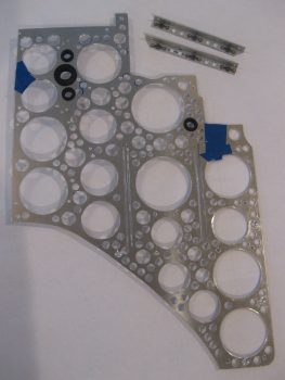
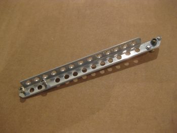
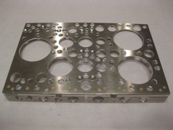
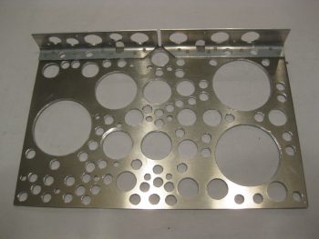
The best plans rarely account for everything, and as far as the Triparagon is concerned I greatly underestimated the time and effort it would take to simply create the lightening holes.  Thus, when I looked at the Triparagon this morning, after the “last & final” round of lightening holes, I should have been put in the looney bin when I decided I could go just one more round using a smaller 0.190″ drill bit.  So that folks is exactly what I did: an entire FINAL round of lightening holes!

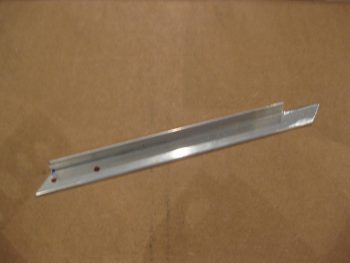
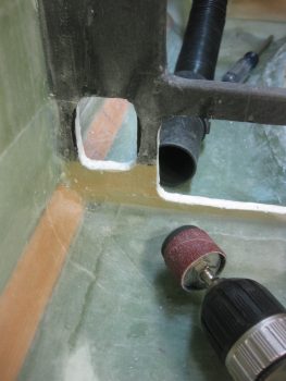
I also noted that I could actually remove a bit more weight by rounding the corners of the vertical Triparagon plate.  So before I started in on the final round of 0.190″ lightening holes, I drug out my Saber saw and did some cutting.  After I finished rounding off the corners, I then got to work drilling the small holes.  If the area could take a 0.190″ hole and still have a good amount of metal for strength, it got drilled!

Rounded corners

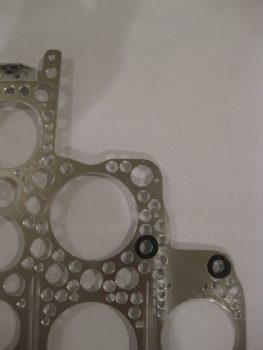
After the final round of lightening holes was finished, I then set about for the next 3-1/2 hours in chamfering the holes.  I did it the in my typically poor man’s milling machine style by using my drill press with a slightly larger bit, and going very slowly (the downward motion, not the bit) to create a nice edge on each hole, albeit a fair number of them are a hair off center.

More Swiss cheese!

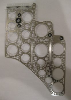
After chamfering the smaller holes I then finished the edges of the larger holes. [I had to finish up the last handful of smaller holes with a cordless drill since my chuck assembly literally fell out of my drill press while chamfering one of the holes.  Luckily the hole wasn’t next to anything important because it created a decent sized crater where a nice lightening hole had once existed!]

I then drilled and installed 6 larger rivets across the top of the cross shelf mounting brackets to permanently mount them to the Triparagon vertical plate.  Afterwards, I drilled 0.190″ lightening holes in-between the rivets.

Top cross shelf brackets riveted in place

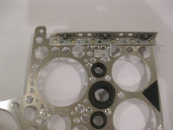
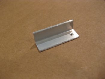
Then, for the first time, I officially mounted the cross shelf to the Triparagon vertical plate!

Cross shelf permanently mounted - but removable!

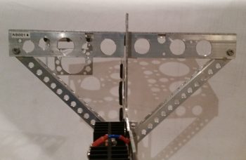
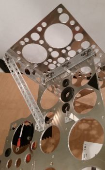
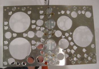
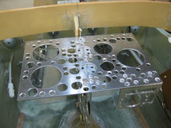
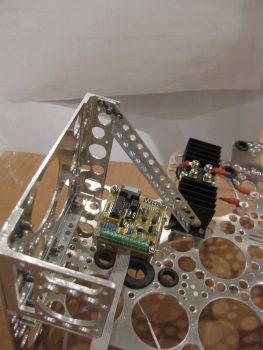
Here’s a top view of the cross shelf.  You can see the lightening holes of the cross shelf mounting brackets through the lightening holes in the cross shelf.

Cross shelf permanently mounted - but removable!

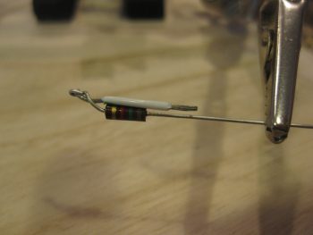
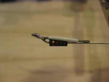
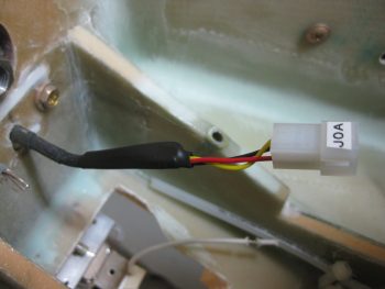
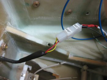
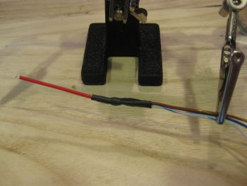
And another view of the cross shelf, after I installed the diagonal support arms (which again requires mounting the Schottky diode heat shrink).

Diagonal support arms installed with cross shelf

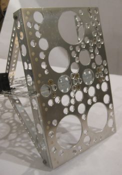
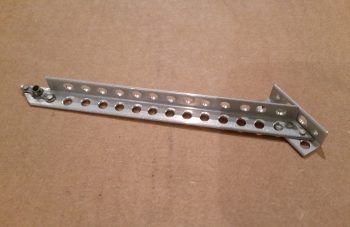
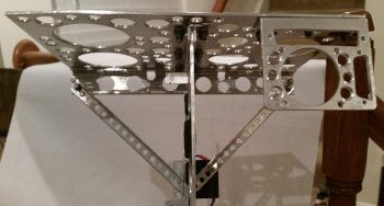
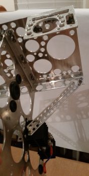
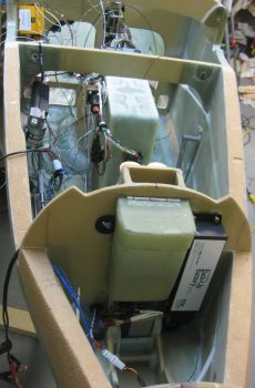
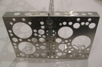
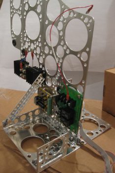
Here’s a side view of the finished & assembled Triparagon structure.

Triparagon - side view

I then took it down to the shop for one final test fit (and the requisite round of pics!) before remounting all the electrical components back onto it.  I figure it will be a long time before the bare Triparagon structure sees the light of day again.

Triparagon final test fit

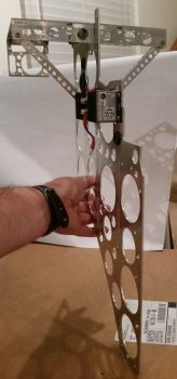
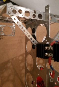
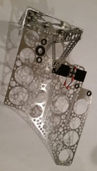
Here’s a shot primarily showing the diagonal support arms and the front cross shelf overhangs.
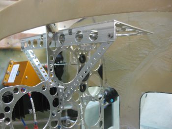
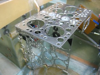
Triparagon final test fit

And from the right…

Triparagon final test fit

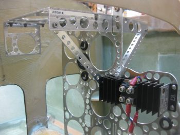
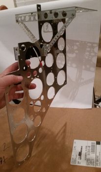
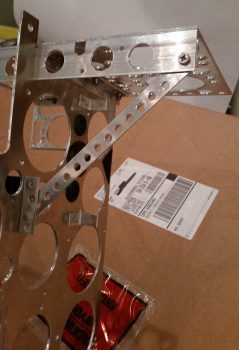
Here’s a shot from the aft side of the now permanently (but removable!) cross shelf attached the vertical Triparagon plate.

Triparagon final test fit

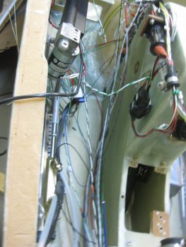
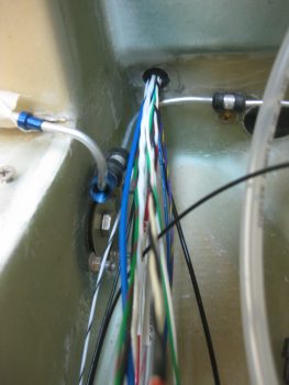
I removed the Triparagon from the fuselage avionics area and took it back upstairs to start reattaching the electrical components to the structure.

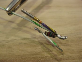
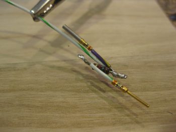
Besides the required Schottky diode heat sink, the next items to get attached were the back-to-back attached AG6 warning annunciators (AG6A & AG6B).

AG6 Warning Annunciators remounted

Remounting Triparagon components

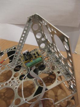
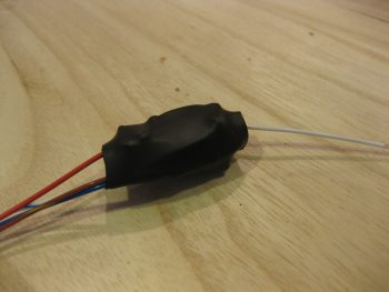
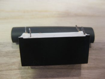
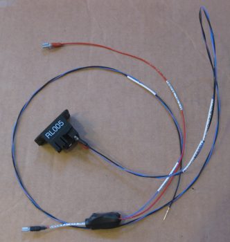
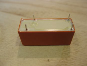
I then remounted the Roll Trim relay board.

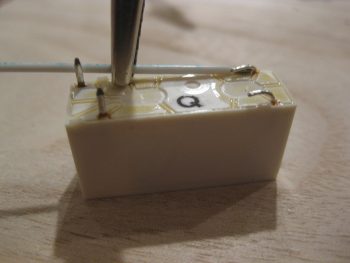
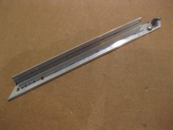
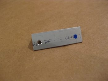
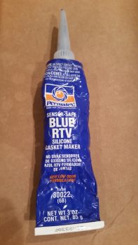
Now, I wanted to use some type of thread locker but all I had was red & blue.  I went out on a quick quest to find some purple Loctite, for small diameter screws, but as per usual it was a lesson in futility after visiting 3 different stores.  I remembered reading a forum post regarding thread locker from our friends in the VANs world.  Sure enough I found it.   A guy on the forum reported success with grey silicone RTV, and recounting in my mind the characteristics of the blue RTV I had used (not wisely!) to protect the bolt threads of my canard mounting tabs when I glassed the shear web, I figured I would use that vs. an actual thread locker (second pic below). To be clear, I only used it where I wasn’t using a nut on the other side of the plate to secure a screw.

Roll Trim control board remounted

Blue Silicone RTVI then remounted the 4-port USB hub with locking screws & nuts, and then the Avionics ground bus (G5) and Carbon Monoxide detector (CO), both with blue RTV.

Avionics GND bus/CO dectector/USB Hub remounted

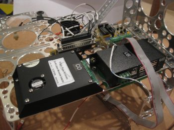
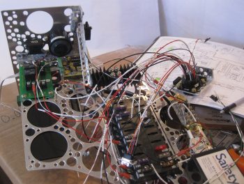
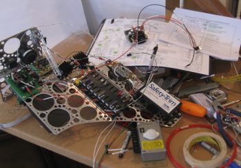
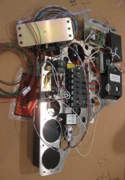
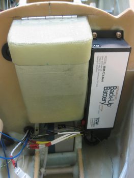
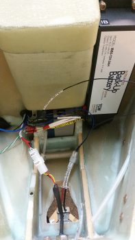
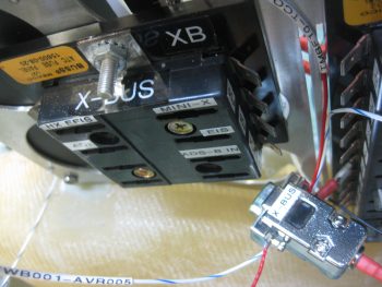
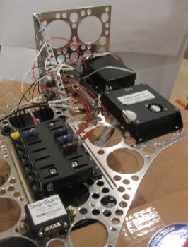
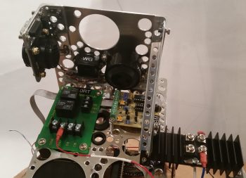
I then remounted the Main Bus and E-Bus, which share the top 2 screws & AN3 nuts, and thus are physically clamped onto the Triparagon plate.  The bottom screws for the E-Bus got blue RTV.  Only one bottom screw for the Main Bus got blue RTV because the other one is shared as the aft mounting point for the SmartStart module, so it too gets an AN3 nut.  Below you can see the E-Bus and the SmartStart module mounted on the left side of the Triparagon.

E-Bus and SmartStart module remounted

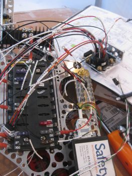
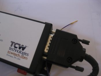
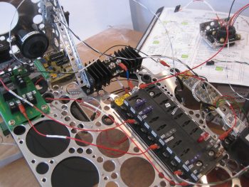
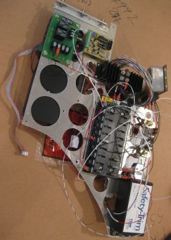
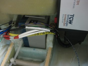
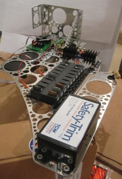
And here’s the right side of the Triparagon, with the Main Bus remounted.  I also remounted the Trim relay box (TCW’s Safety-Trim) which shares its aft upper screw as the forward mounting point for the SmartStart module on the opposite side.  The other 3 stainless steel countersunk screws on the Safety-Trim box got slathered up with blue RTV.

Main Power Bus and Trim Relay box remounted

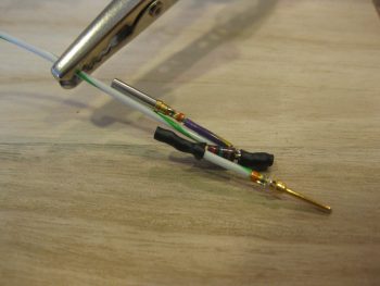
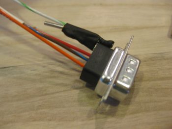
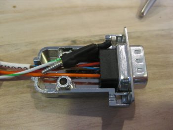
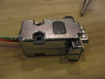
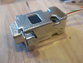
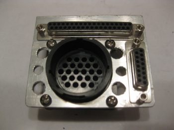
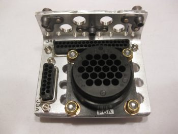
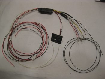
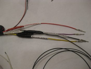
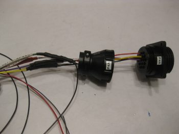
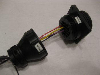
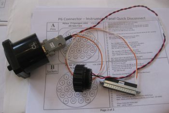
I then remounted the PQD connectors: 1 AMP CPC connector and 2 D-Sub connectors.

PQD connectors mounted

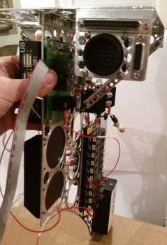
Here’s a shot of the aft side of the remounted PQD connectors.  Notice how bare the area is just to the right of the PQD connectors …

PQD connectors mounted

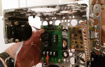
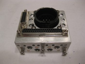
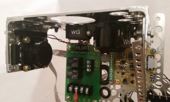
Not anymore!  I mounted the gear & canopy warning module (WG) and the Piezo warning horn (WH) in the space just forward of the PQD connectors, on the bottom left side of the cross shelf.

Gear/Canopy and warning horn

Here’s another shot of the installed gear & canopy warning module (WG) and the Piezo warning horn (WH).

Gear/Canopy and warning horn

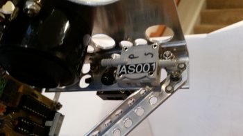
I then got to work on doing a final mount of my 3 airspeed switches.  Airspeed switch #2 and #3 were fairly EZ, but #1 was a bit of a pain.  I had to remove and trim down the top of the horizontal arm piece on the left diagonal support to allow clearance for the airspeed switch.  Specifically clearance for one of the FastOn connectors that mount on the underside of the airspeed switch, which was not accessible with the current configuration of the diagonal support arm.

Airspeed switches #2 and #3

After trimming the diagonal support arm, I remounted it and test fitted airspeed switch #1. There was still just a bit of interference with the support arm, but I had removed all that I could before actually cutting into a lightening hole.  I found a 3/4″ 4-40 spacer and cut it in half, and tried out the 3/8″ spacer (vs the 1/4″ spacer I was already using!). Voila!  That did the trick.  I then mounted airspeed switch #1 to finish off the mounting of all the “CrackerJack” parts.

Airspeed switches #1, #2 & #3

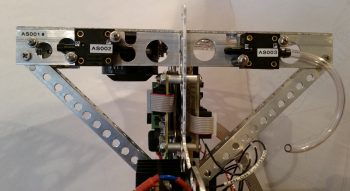
Here’s a closer, albeit blurry, shot of the right-side mounted airspeed switches.  You should still be able to make out the airspeed set screw for airspeed switch #1 through the hole in the cross shelf overhang.

Airspeed switches #1 and #2

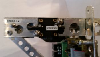
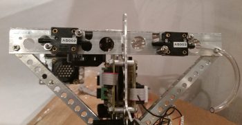
And here’s a shot from behind, showing the staggered #1 and #2 airspeed switches.  Note the clearance between airspeed switch #1 and the top of the diagonal support arm.

Airspeed switches #1 & #2 - aft view

The final, no kidding, total weight penalty for installing the Triparagon is right at 1.2 lbs.  Of course if you take into account the amount of wire in runs saved, and the myriad of separate mounting hardware, glass and epoxy to mount things on the sidewalls in the avionics area, I’d argue that there’s at least a quarter of a pound there, making the comparative weight penalty more around 3/4 of a pound.  The weight comparison also doesn’t take into account the increased ease-of-use for the Triparagon.

Tomorrow I actually need to get some stainless steel hardware that I thought I had on hand to swap out with some of the hardware I used today.  With Christmas getting closer I still plan on getting stuff done on the build, but it will be a tad less than normal.
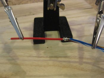
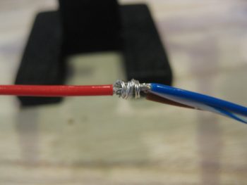
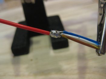
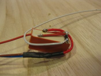
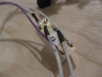
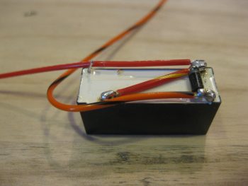
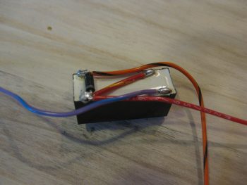
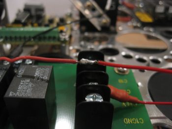
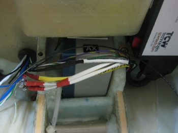
 

Chapter 22 – Lightening the Load!

I started the day off by finalizing and pulling the trigger on both a Mouser order and a quick ACS order (it appears that someone –ha!– forgot to order some 22 AWG shielded wire…).

I then got to work on the Triparagon vertical plate.  I stripped off the cross plate, diagonal support struts and the Schottky diode/heat sink and got to work for the last and final serious round of lightening holes.  The starting weigh-in this round for the Triparagon vertical plate, with the grommets and cross shelf brackets including 6 x K1000-3 nutplates, was 0.82 lbs.  My goal was to get the weight down by another 0.2 lbs.

After drilling a 1″ lightening hole and 10 each 5/8″ holes, it weighed in at 0.78 lbs.  At this point it was really time to get work.  As you can see, I Swiss cheesed this thing like no tomorrow to drive the weight down to its possible lowest, without sacrificing strength.  I used an 11/32″  (0.344″) drill bit to get all the in-between spots that I could while, again, still leaving enough meat on the bone for this thing to be as strong as it was before.  It is an interesting concept that you can remove so much material, but when I flex it, it feels as strong as when it was a solid panel.

Making Swiss Cheese!

After squeezing in as many 11/32″ holes as I could (I have about 3-4 more places I can get with a slightly smaller bit), and drilling 3/16″ lightening holes on the upper arms of the cross shelf mounting brackets, I’m sitting at 0.68 lbs. for these components.  Obviously, this isn’t quite as low as my 0.62 pound mark, but I’ve squeezed just about all the weight out of this thing that I reasonably can.

When I weighed the entire Triparagon assembly as a whole, it weighed in at 1.18 lbs, including hardware.  Since I have just a handful of lightening holes to drill, if I add in the weight of the aircraft-side mounting tabs and the hardware, I’m right around, or just a hair over, 1.2 lbs.  My initial goal was a pound or less for the entire Triparagon’s added total weight, so an extra 3.2 ounces ain’t bad… I can definitely live with that.

Thus, as Vince Lombardi said, “Perfection is not attainable, but if we chase perfection we can catch excellence.”  Clearly I didn’t reach my ‘perfect’ requirement, but I got pretty close.  In putting in a lot of effort to get as much weight off these components as possible, I feel like I’ve definitely achieved excellence in that regard.

Tomorrow I’ll spend a few hours chamfering the myriad of lightening holes I drilled today. I’ll then rivet the cross shelf mounting brackets in place, drill lightening holes in between the rivet locations and call the Triparagon build complete!


Chapter 22 – Triparagon Erector Set

Funny, before I sent a few pics of my progress to my buddy Marco, I was thinking that this thing sure does look like an Erector Set.  Sure enough, Marco texted back the same thing so I figured it would be a fitting title for today’s post.

I started off with a couple of shots of the Triparagon showing how it looks as removed from the airplane with all the electrical accoutrements attached.  You can see on the right side that there’s a big bare spot where the original X-Bus once resided.  Now I have more space to mount more toys in the future!

Removed Triparagon - Left side

Removed Triparagon - Right side

The goal for the day was at a minimum to get the diagonal supports in for the cross shelf. I was able to accomplish that.  I was also trying to get the last round of lightening holes drilled on the Triparagon vertical plate . . . that did not happen.

I got to work by stripping the Triparagon of all of its encumbering components, ensuring that each component and its hardware got bagged so as to keep track of they myriad of little pieces parts.

I then gathered up my 1/2″ x 1/2″ by 1/16″ thick 2024 angled aluminum extrusion and did a bunch of figuring out, measuring and head-scratching to configure the right side diagonal support.  Because of the location and angle that it intersects with the vertical plate, I went ahead and decided to simply mount it with 2 x 4-40 screws to the aft end of the Schottky diode heat sink, which in turn is of course mounted to the Triparagon vertical plate.

After getting all my measurements and angles finalized, I marked up the extrusion and cut it.  Since it’s really cold outside and it was more trouble than it was worth to pull out a miter saw, I simply cut this by hand using my German hack saw.  I needed to remove a length of one side of the angled extrusion on the top-oriented end to make room for the static line attached to airspeed switch #1.   I cut the perpendicular side with my hacksaw, but for the rip cut at the corner edge I used the Dremel with a cutoff wheel (pic is a bit blurry).

Right diagonal support arm

I then drilled a hole for a #8 screw through both the diagonal support and the right corner of the cross shelf overhang mounting tab.  I then drilled and riveted a K1000-8 nutplate to the top end of the support arm.  As you can see, I also marked the diagonal support arm with lines running the full length to drill lightening holes.

Right diagonal support arm

I then drilled a series of 3/16″ lightening holes.  Although I used my drill press, they’re still far from perfect.  But they lighten the piece and provide holes to secure wires to, so requirement met!

Here’s a shot of the finished right-side diagonal support arm for the Triparagon cross shelf.

Right diagonal support arm

On the left side I had nothing to mount the support arm to on the lower end of the arm, so I cut a 1.55″ piece of 1/2″ x 1/2″ by 1/16″ thick 2024 angled aluminum extrusion to make a small mount bracket.  I planned to have the mount secured to the vertical Triparagon plate using the same 2 screws that also secures the aft edge of the Schottky diode heat sink (different screws than the 4-40 ones used above to mount the right side support arm).

I set the length (technically height) of the mounting bracket so that the screw holes would be about 0.2″ in from the top & bottom edge, so after cutting the mounting bracket to 1.55″ I simply marked and drilled a hole 0.2″ from the edge.  I also tapped the hole to accept a 4-40 screw.  I can of course drill this out later if I simply want to use a nut with the screw later on.

Left diagonal support arm bracket

I then mounted the bracket in place, removed the lower screw and marked the hole with a Sharpie.  I then removed the bracket and prepped it for drilling.

Left support arm bracket marked for drilling

Jumping ahead (I had a pic or two in-between, but they came out frustratingly blurry!), here’s the completed left side diagonal support arm.  Note that I used rivets to secure the arm to the mounting bracket.  Also note that I drilled a number of lightening holes in not only the support arm, but the mounting bracket as well.

Left side support arm

I then mounted the diagonal support arms in place on the Triparagon and snapped a bunch of pics.

Here’s a shot from the front right side of the Triparagon looking aft.

Triparagon - Right side view facing aft

And another one from the front left side looking aft.

Triparagon - Left side view facing aft

A head on shot looking aft.

Triparagon - View facing aft

And what you would see if the instrument panel was see-thru.

Triparagon - View facing forward

A bit closer from the front right & left looking aft.

Triparagon support arm - from front right

Triparagon support arm - from front left

A low angle shot looking from the left side forward.

Triparagon support arm - from aft left

And the final low angle shot looking from the right side forward.
Triparagon support arm - from aft right

Tomorrow I’ll remove the cross shelf and the diagonal support arms and drill the final round of lightening holes into the vertical Triparagon plate, which will be the end of my Lightening hole drilling on this thing!  Once done I’ll clean up the holes and then start back with the final (permanent) mounting of the electrical components on the Triparagon.  Then over the next few days I’ll get as much of the cross-wiring and interconnects knocked out as I can. Once that’s done –as well as a few minor Adel clamp hard points, click bonds, etc. floxed & glassed into the avionics bay area– I’ll call it quits on the electrical stuff for a while AND… get back to work on the wheel pants!


Chapter 22 – Electric Push

I started off today with the intent to finish the edging on the lightening holes on the Triparagon cross shelf.  But that didn’t happen.

What did happen was I did a test fit of the IBBS & it’s ‘new & improved’ wiring harness.  Part of that test fit was to ensure that ALL the wires –not just the IBBS wires– fit through the hole & protective grommet that traverses the Napster bulkhead.  And, as per usual, since I just happened to be in the neighbor hood, I figured I couldn’t really test if the wires fit unless the actual wires (and cables) that will run through this transit hole are used in the test.

So I decided to go ahead and get the landing landing light and taxi light wiring/cabling knocked out.

First up was the landing light.  The installation manual for the AeroLEDs Sunray Plus landing light calls for using 20 AWG shielded wiring to power the light.  I only had 22 AWG on hand, so I used it since I’m confident that it will work since the actual run is only about 5 ft vs 3-5 longer than that if it was buried out at the end of a wing somewhere in a “typical” install.

I started by stripping away about 2″ of the outer jacket.

2-wire 22AWG shielded landing light cable

I then wrangled and cut the shielding wire.

Wrangling shielding on landing light cable

And soldered a piece of 22AWG black wire for the ground wire.

Ground wire soldered to shielding on landing light cable

I then heat shrinked it all up: red to symbolize positive power, and black for the negative ground wire.

Landing light cable end reinforced with heat shrink

I then terminated the wire ends with mini-Molex socket connectors.  Note that the black pigtail wire will actually terminated on a mini ground tabs block that I’ll have mounted onto the negative post of the battery.  [Note: Although I’m not a fan of Molex connectors for the larger, multi-pinned connectors, the mini-Molex connectors work just fine for 2-6 wire applications … just my opinion, YMMV].

Landing light cable min-Molex sockets & ground pigtail

I then prepped the landing light side.  I had 2 extra wires that I simply folded back onto the main cable and heat shrinked in place.  I then terminated the remaining 3 active wires (red for light power, black for ground, yellow for wig-wag) with mini-Molex pin connectors.

Fuzzy land light wires prepped & pins crimped on

And then attached the 4-pin mini-Molex connector (J0, A side).

mini-Molex connector (J0A) housing in place

After running the landing light cable through the hole & grommet in Napster, I then connected the J0B side of the landing light connector to the J0A side.  Looking good!  Note in the pic above and below the white wire leads of the taxi light, those will change in a bit.

Landing light cable connected to landing light

I had previously installed the IBBS to test its fit.  As a side note, after some investigation I realized that the end of the IBBS box cover (that has the “IB” label attached) was bowed out a bit & thus not allowing me to use normal sized AN3 nuts.  So I removed the IBBS cover, gently pressed the end back straight, reattached it and . . . Voila!  It mounts perfectly!

Back to the wiring… Get this: to get all the wires to fit, I actually have to removed the grommet out of the lower wire transit hole in Napster, then push the 2 knife splices through, then the PIDG FastOn connectors for the IBSS power & ground wires, then reinsert the grommet before the rest of the wires can go through.  Also, I can’t terminate OR LABEL any more wires at this time if they are going to fit through that hole…. VERY TIGHT FIT! Which is good because of course it keeps the wires secure.  It also gave me a chance to try out my “Wire Spoon” that I picked up from Stein a million years ago and have never used.  Works great and really does allow you to insert wires through the hole in the midst of a big wire bundle that you would otherwise not be able to get in there.

IBBS test install & wire run to ensure fit/clearances

The next couple of shots are simply closeups of the IBBS wiring harness crossing over the nose gear back up battery, just underneath the nose tool box, and exiting out of the nose through the lower hole in Napster.  (You get a better shot of the IBBS harness “U-Turn” in pic #2).

IBBS wiring harness in & test fit wires thru BH

IBBS test install & wire run to ensure fit/clearances

Here’s a long view of “Electron Alley” showing the myriad of wires that are currently in play and that I’m contending with.

"Electron Alley" - lots of wires!

I then set to work to terminate and wire up the Taxi Light with a 22 AWG blue wire for power (blue just happens to be the color of the wires used in the Infinity stick grip for that switch, so I carried that color all the way through) and a 22 AWG black wire for ground.  Note that I also labeled the wires on the light side, something I didn’t have space to do on the landing light.  I finished off the installation using a 2-pin mini-Molex connector (J7) that I bought well over a year ago specifically for the taxi light connection.

Taxi Light connector & wiring

Here’s a closer shot of ‘Electron Alley’ . . .

"Electron Alley" - lots of wires!

And a shot of the lower wire transit hole in Napster from the aft side.  The wires you see are currently all the wires that I plan on having transit through this hole (yes, things can change, thus the emphasis on the word “currently”!).

Aft side Napster BH wires thru hole and grommet

I also wanted to get a pic of the old ATC fuse block X-Bus (left) compared to the new 9-Pin  D-Sub X-Bus (right).  As I pointed out before, this modification will save space, weight and complexity (e.g. no individual fuses).

Old vs New X-Bus

I was heading out to dinner with a buddy of mine, but before I ran out I wanted to get one more thing finished for the evening: widen the lower left hole in the instrument panel bulkhead to allow the P4 connector, which was just a tad too big (note the black markings on the sides of the hole) to fit.  I used a sanding drum on my drilled, fired up my shop vac and went to work.

Widening lower left hole in IP BH for P4 clearance

Less than a minute later . . . Voila!  Now the P4 connector just fits through the hole!  My next step will be to add an Adel clamp to keep the throttle handle cable secure.  I would like to reiterate my ongoing theme here by pointing out that this is the type of stuff I really want to get figured out before I close up the nose, while I have infinitely much more access to work on it all.

P4 connector access thru IP bulkhead

Tomorrow I’ll continue on with my push to knock out the avionics area electrical stuff, as well as get the Triparagon install finished. (Then, on to the wheel pants!)


Chapter 22 – Landing Brake Wiring

Today I started out by finishing up the lightening holes on the Triparagon cross shelf.  I drilled small 3/8″ holes in literally every spot that there was space to, again to get this thing as light as possible without compromising strength.  I removed the PQD bracket to drill lightening holes on the cross shelf above where the bracket mounts.

Triparagon cross shelf - Top

After drilling the last of the lightening holes, I then spent a good hour and a half deburring the holes and cleaning up the cross shelf.  I still need to finalize the deburring, but I at least got the rough stuff off the hole edges.

Triparagon cross shelf - Bottom

I also drilled lightening holes in the PQD bracket, which again I need to finalizing the deburring on those holes as well.  I then mounted the P6, J3 and J4 connectors.

PQD connectors & Bracket

Here’s another view from the top.

PQD connectors & Bracket

And an aft bracket view (technically a forward view).

PQD connectors & Bracket

I then spent a couple of hours prepping my Jack Wilhelmson Landing Brake wiring harness.  Below you can see the included switch panel for mounting the switch and LED lights to the instrument panel.  I removed that switch since I replaced it with the switch in the throttle handle to control the Landing Brake, which means that the wiring goes through the P4 connector.

The majority of time I spent working on this bad boy wasn’t the actual physical wiring stuff, but in tracking down, confirming & verifying what wires went where to label them correctly.  Again, since I’m utilizing connectors now in my electrical system wiring scheme, much of my previous A → B wiring is now A → ⊗ | ⊗ → B where ⊗ is the connector.  Since many of my wire labels are now outdated, I simply crossed out the old label with a Sharpie and rewrote the new labels by hand to use up my stock of “bad” labels on this wiring harness.

Landing Brake wiring harness

Since the wires coming out of the relay decks were too short to comfortably terminate into the P4 connector, I had to extend these wires.  Instead of soldering them, I went the lazy route this time around and simply used butt connectors.  I then used heat shrink over the crimped butt connectors.  As you can see, I finished labeling all these harness wires, and then crimped AMP CPC pins on the ends of the 4 Landing Brake wires that will get terminated into the P4 connector.

Landing Brake harness wires AMP CPC pins

Here are the 4 Landing Brake wires terminated into the P4 connector.  Note that I slipped the cable clamp into place before terminating the wires.

Landing Brake harness wires in P4 connector

A closer shot of the Landing Brake wires in the P4 connector (A side).

Landing Brake harness wires in P4 connector

Tomorrow I’ll press forward on the Triparagon and the avionics bay wiring.