Chapter 9 – Wheels on ground!

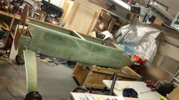
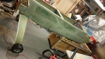
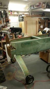
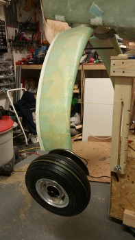
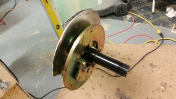
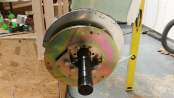
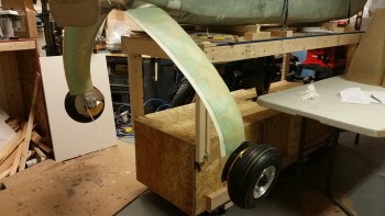
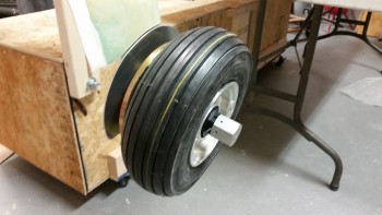
Tonight was a milestone in that it was the first time the fuselage has rested on the main wheels … ever!

I lowered the fuselage dolly platform to get the fuselage as low as possible to slide it aft on the fuselage dolly and thus get the main gear wheels on the floor.

Setting main wheels on the deck

Forgive the camera angles, but I was backed up all the way in the corner and trying to get as wide angle of a shot as I could!

Main wheels on the deck

After I got the fuselage set so I could access the CL on the belly, I started attaching straight edges, running strings and plumb bobs, etc. to double check the toe-in on each side.  As I suspected, I jacked up the toe-in pretty good after I had set them correctly from the first go around with the gear in the air.

When I flipped the fuselage over I had double-checked the toe-in and it seemed to be either negative (wheels pointing out) or not enough.  So when I mounted the wheels I sanded down the mounting pads to reset the toe-ins correctly.  Of course, as often is the case, I should have left well enough alone!

Fuselage on main gear wheels

With access to the CL mark on the belly this evening, I could actually determine the CL to double check my toe-in measurements.  After it was all said & done this evening, I confirmed that my left wheel assembly is mounted approximately .08″ farther outboard than my right, which is not enough for me to worry about any further.

However, my toe-in is much more than it technically should be with each side a hair over 0.3″.  I figure that per plans the max you want to be at is 0.45″ combined, and I’m sitting just under 0.65″ combined.  However, since my plane will have a bigger engine and weigh a couple hundred pounds more than what Burt was originally planning these birds to weigh in at, I’m not going to make something not-so-great even worse by mucking about with it.  At least not right now.  I’ll wait until I do my high speed taxi tests to see how my tire wear is progressing & then adjust fire from there.

Tomorrow I’ll get the fuselage dolly out from under the front of the fuselage, lower the nose gear and play around with that a bit and grab some pics for prosperity sake.  I’ll then start working on prepping the wheel pants for install.


Chapter 9 – Wheels Installed

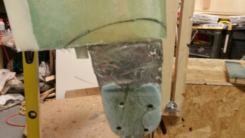
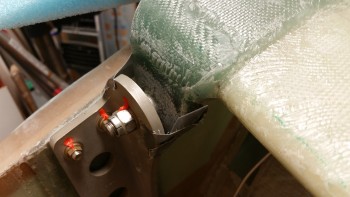
I started off today by test fitting the right heat shield onto the gear leg.   The foam of the lower gear fairing extended out enough to make it impossible to mount the heat shield in its correct position.

Test mounting right heat shield

I marked the perimeter of the heat shield onto the lower gear leg in preparation to cut the glass & foam away from the lower gear leg.

Right heat shield gear leg notch marked

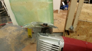
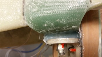
I then used the Fein saw to cut away the glass & foam away from the lower gear leg to allow the heat shield to fit correctly in place.

Cutting right heat shield gear leg notch

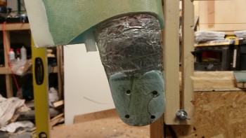
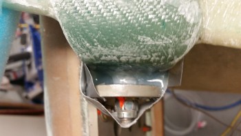
Here’s a shot of the trimmed lower right gear leg.

Right heat shield gear leg notch cut

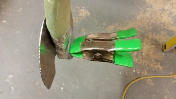
I then remounted the right gear heat shield, which fit fine.  I held the AN4-22A bolts in place with spring clamps.

Test mounting right heat shield again

I then repeated this process on the left side to clear the lower gear leg glass & foam (and micro) to allow the left heat shield to fit correctly.

Left heat shield gear leg notch cut

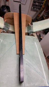
I ran a line down the fuselage CL to double check the toe-in, and even sanded the gear axle mount pads, but after dialing them in as best I could I realized that I was about as close as I was going to get at this point.  I’ll do some final checks with the fuselage actually sitting on the ground.

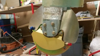
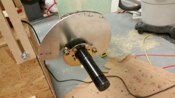
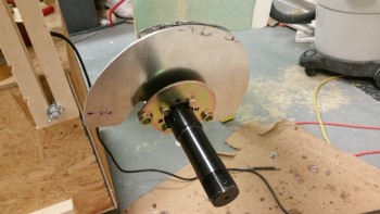
After messing about with the toe-in and dialing it in as best possible, I then mounted the axle, brake mount assembly and the heat shield onto the right gear leg.

Mounting right axle & heat shield

I then mounted the right brake rotor and brake caliper assembly.

Mounting right brake assembly

Here’s an inside view of the right brake caliper assembly.

Inside right gear brake assembly

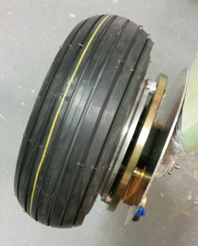
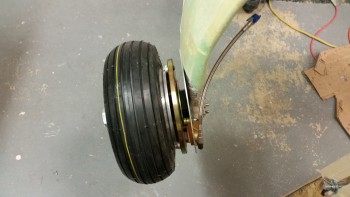
I then installed the wheel & tire onto the right side gear leg.

Right wheel & tire installed

Here’s another shot of the right wheel installed.

Right wheel & tire installed

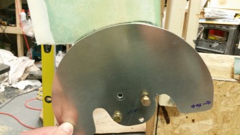
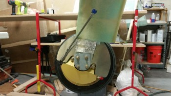
After installed the right wheel, I installed the left axle, heat shield and brake mount assembly.  Unfortunately, after tightening up all the nuts on the AN4-22A bolts and then attempting to mount the rotor & brake caliper assembly I realized that I had mounted the brake mount assembly upside down… doh!

Left brake mount installed incorrectly

This is how it should look!

Left axle & heat shield installed (

I then mounted the left brake rotor & brake caliper assembly.

Left brake rotor & assembly installed

Left brake rotor & assembly installed

Here is a shot that I’ve been wanting to take for a long time: both wheels mounted!

Wheel assemblies installed

I then mounted the 9.5″ braided stainless steel Stratoflex brake lines that will connect the brake caliper to the stainless steel brake line tubing.

Right stainless steel brake line installed

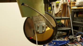
Here’s an inside view of the right (top) and left (bottom) braided stainless steel Stratoflex brake lines.

Right stainless steel brake line installed

Left stainless steel brake line installed

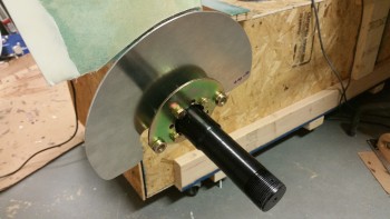
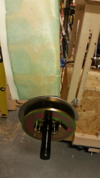
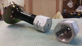
I then mounted the wheel axle nut sleeves to both Matco axles. These are sold by Van’s Aircraft for mounting the outboard side of the wheel pants.

Van's threaded wheel pant axle mount

With the gear fairings finished and the wheels now mounted, I will start the process of installing the wheel pants.  After I get the wheel pants installed, I’ll then flip the fuselage back over, finalize installing the brake lines.  Finally, I’ll then work on the RAM air scoop and aft fuselage extension over the hell hole area.


Chapter 9 – Gear fairing final steps

I started out this morning by whipping up some thick micro and applied it to the trough along the TE on both gear fairings.  I then peel plied the micro with 1″ wide peel ply tape.

Right gear fairing micro'd TE

Left gear fairing micro'd TE

Later on in the afternoon I razor trimmed the TE on each side.  Then in evening I pulled all the peel ply both off the cured TE micro and the off the topside UNI overlap onto the lower UNI skin.  I then sanded the aft fairing TE on each side.

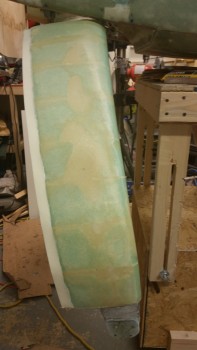
Gear fairings - aft view

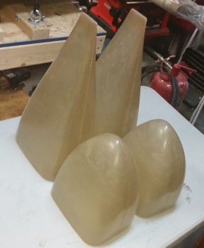
After I finished up with the gear fairing, I rounded up all the wheel pant components to have them on hand as I start moving towards installing them.

Wheel pants "inventory"

I’ll be gone most of the day tomorrow (Friday) so I won’t be working on the plane, and Saturday will be a bit busy as well.  I will be attempting to check the Toe-in Saturday, Sunday at the latest.


Chapter 9 – Gear fairing tops glassed

As I mentioned in my project update, I decided that I needed to flip the fuselage right side up to glass the top sides of the gear fairing.  I hadn’t planned on flipping the fuselage for quite a while, but plans change when one (read: ME) fails to account for issues such as the heat shields blocking access to the lower outboard gear leg thus preventing glassing the topside gear fairing if the wheels are mounted.  Sequencing is key in my opinion for optimizing the build schedule, but in this case there was no way around it: the fuselage was going to have to get flipped back upright.

No big deal of course.  I did re-wicker my build steps though to account for the fuselage being right side up.  The plan now is to glass the top of the gear fairings, then do a final check & possible tweak of the toe-in, and then mount the wheels/tires/axles/brakes/heat shield.  With the wheels in place, and the fuselage upright, I can then mount the wheel pants and be finished with all things gear related except for finalizing the brake line install.  As for the stainless steel brake line install, the new timeline works out fine since my stainless steel capable flaring tool won’t be here for another couple weeks.

So I started off today by trimming the TE of both the right & left gear fairings.
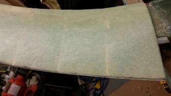
Gear fairing TE marked for trimGear fairing TE marked for trim

Once I got the gear fairing TE squared away, I needed to flip the fuselage.  I did about 10 minutes of head scratching before I finally remembered that I had designed the fuselage dolly so that it could match up height-wise with my portable fold out table.  I set the table as you can see below and it matched up great after I set a couple 2x4s with cardboard protectors in place to get the heights equal & matched.
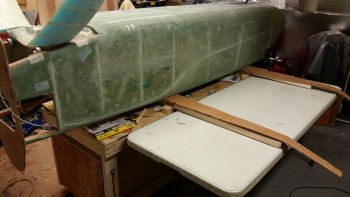
Flipping fuselage

I then very carefully & slowly tipped over the fuselage onto the foldout table using the gear legs as a lever.
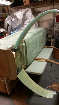
Flipping fuselage

Here’s a shot from the inside cockpit side… something I haven’t seen in while.
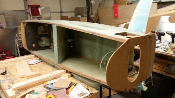
Flipping fuselage

I then slid the fuselage sideways back onto the fuselage dolly.
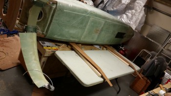
Flipping fuselageFlipping fuselage

And then flipped the fuselage right side up back onto the fold out table, and then once again slide it over onto the fuselage dolly.  Once I had it blocked correctly underneath, I then reattached the securing straps.
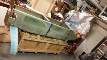
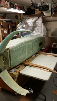
Fuselage flipped

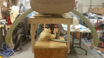
Another shot of the flipped fuselage from the aft end.
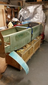
Fuselage flipped

Clearly the bottom side of the gear is close to the ground, someplace that I don’t want to spend a lot of time messing around trying to layup glass.  Luckily my fuselage dolly elevates!

Interestingly, with the amount of weight that my fuselage is packing on, my drill couldn’t handle the torque of getting the dolly platform to raise.  Actually, I should say that my hand couldn’t handle the torque of the drill wanting to rip out of my hand.  So I grabbed a ratchet speed handle and raised the platform its first few inches manually before switching to the drill. [I guess this demonstrates the torque required on the nose gear that Jack discusses in his instructions: to have the gear up at least a foot before climbing in & having it raise passengers from the flat deck position.]

As you can see, I raised the platform its full height giving me (and thus my back!) a much better working height for glassing the top side of the gear fairings.
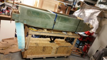
Fuselage raised up in the airWith the gear height at an acceptable working height, I then marked the right gear fairing a half inch (0.5″) forward of the TE.  This will allow for a good top fairing glass to lower fairing glass bond.
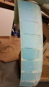
Right side fairing TE marked for trim

I used a razor knife to remove the foam, and then the Dremel Tool to remove the micro that had oozed out the aft end of the foam piece junctions.  I also cleaned the dead foam & micro off the freshly exposed TE lip.
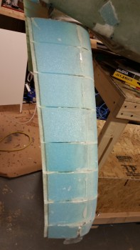
Right side fairing TE trimmed 0.5"

Then came the not so fun step.  For some weird reason the “2-piece clamping method” that I used on the right side fairing didn’t work so well.  I could run my hand up & down the outer surface of the right fairing and depress the foam inwards towards the original gear.  Clearly there were a fair number of air gaps between the applied micro layer and the foam fairing pieces on the right side fairing.

With the size of the air pockets the practical solution was far beyond injecting epoxy or anything else under the foam pieces, I was going to have do a sort of rebuild on this fairing.
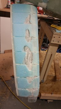
Right side fairing unattached foam removed

Enter X-30 Expanding Foam.  I know a lot of builders have used this foam for a variety of things, but I personally haven’t used it before.
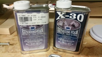
X-30 Expanding Foam

After reading the directions I decided that I would heed the warning of so many builders before me that this stuff really does expand 30 times its initial volume.  With this in mind I marked equal pencil lines in 2 small cups less than an inch up for parts A & B of the X-30 foam.
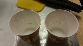
Part A & B cups marked for foam

I poured the part A & the part B X-30 foam in the separate small cups, and then as per instructions mixed them in the larger cup.
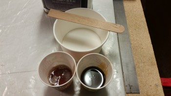
Ready to roll with expanding foam

For those not familiar with the X-30 Expanding Foam, it has a 15-20 second mix time before its immediately poured and/or applied to the surface.  I didn’t set up any dams or anything since I applied it straight to the surface of the right gear fairing.
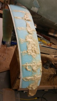
Expanding foam applied to right side fairing

Here’s a wide angle shot of the right gear faring with the expanding pour foam applied to it.
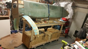
Expanding foam applied to right side fairing

While I let the expanding foam cure some I went to work on the TE of the left gear fairing.  As with the right gear fairing I trimmed the foam 0.5″ from the TE.
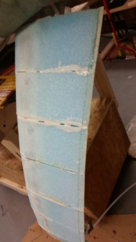
Left gear fairing TE marked for trim

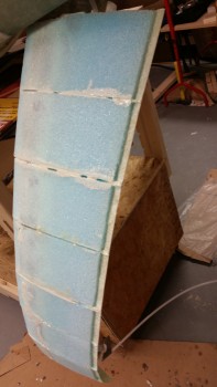
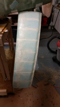
Left gear fairing TE 0.5" trimmed

After finishing trimming the TE on the left side, I turned my sights back onto the right side gear fairing.  I started out using the Stanley Surfoam grater to trim the foam down (left pic) and then used my sanding board to finalize the foam sanding (right pic).
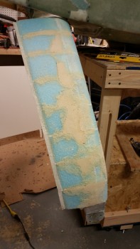
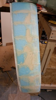
Right gear fairing foam rough shaped

Right gear fairing foam sanded to shape

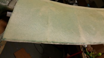
I then cut another 4 pieces of UNI off the roll.  This time around I added a half inch to make the width 11-1/2″ wide vs the underside 11″ wide.  I cut the UNI at a 30° angle across the entire roll.

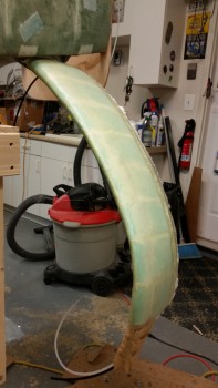
I then mixed up some flox and applied it to the left top gear fairing foam & glass junctions at both the LE & TE.  I then micro’d the surface of foam gear fairing before laying up 2 plies of UNI oriented in opposite 30° angles.  I overlapped the 2 plies of UNI onto the bottom fairing glass by about 1.5″ the entire length of the LE.
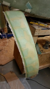
Right top gear fairing glassed

A front shot of the glassed topside left gear fairing.
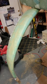
Right top gear fairing glassed

With the right gear fairing glassed I then sanded down the blue foam & cleaned up the micro on the left fairing with the Dremel tool.  Once the fairing surface was prepped, I micro’d the top left gear fairing.
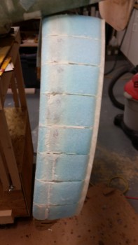
Left gear fairing trimmed & sanded

Left top gear fairing glassed

I then laid up 2 plies of UNI at opposite 30° bias just as I did on the right side gear fairing.
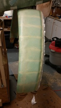
Left top gear fairing glassed

Left top gear fairing glassed

After laying up the UNI on the fairing I ensured that it was trimmed on both sides.  I also peel plied the UNI overlap onto the lower fairing glass on each side.
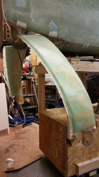
Right & Left top gear fairings glassed

Since I used MGS 335 with slow hardener, I have a few hours before I’ll razor cut the overhanging glass.  When the layup gets to that green point I’ll also apply dry micro to the depression along the TE.

Once I get the gear fairing cleaned up I’ll confirm the toe-in as I mentioned above.


Chapter 9 – Brake Line Install

I started today by continuing the design on the belly air scoop for the ram air intake.  I spent a good amount of time researching the intake nozzle shape & checking my options for what bell mouth-shaped aluminum intakes are available for sale online.  So far I haven’t found exactly what I’m looking for, so I’ll keep looking as I continue to dial in the shape, design & configuration of the air intake scoop.

Designing belly air intake

My main focus today was to get down to brass tax to answer my #1 burning question at the moment concerning my final brake line connections: stainless steel or Nylaflow? (both of which I have on hand).  What I don’t have on hand is a flaring tool for the 3/16″ stainless steel tubing I have on hand ($$) or the fittings I would need to connect up the Nylaflow into my current configuration ($).

The first thing I needed to find out is if the stainless steel tubing would even fit into the channel tubing I emplaced on the aft side of the main gear fairings.  Well, the stainless steel tubing, being a small diameter, was easily bent by hand and with just a little bit of effort & cajoling I got it to slide into the fairing channel.

Testing stainless steel brake line install

Below is a closer view of the inboard side.

Knowing that the stainless steel brake line can be fit into place easily enough, I then pulled the trigger and ordered yet another tube flaring tool that can handle flaring 3/16″ stainless steel tubing.  I don’t have the model or specs in front of me but when I get it in hand & use it I’ll give you a report on how it works.

Testing stainless steel brake line fit

Below is a shot of the outboard side gear with the stainless steel brake line sticking out.  As you can see, there’s plenty of tubing to work with which will allow me to most likely create a service & anti-stress spring loop at the hell hole side of the tubing.

Testing stainless steel brake line fit

I threw together an ACS order along with the flaring tube order which I’ll finalize tomorrow morning.  Again, tomorrow is Monday so it will be a school day & night, so no building will get done on the airplane.


Chapter 9 – Trimming Gear Fairings

I didn’t get a lot done today on the plane build, but I did spend a couple of hours cleaning up the gear fairing layups from last night.

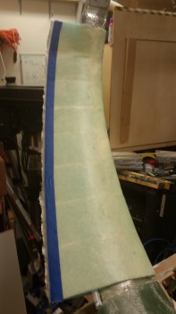
I started by pulling the 2″ wide peel ply off the LE of both sides of the fairings.  I cleaned up the peel ply boogers and then cleaned up the top & bottom fairing edges by trimming away the excess glass with the Fein saw.  I then cut the glass on the LE with the Fein saw using the protective duct tape edge as a guide.  I didn’t take any pics of this until after I finished taping the cut line along the fairing TE with blue painters tape.  I then cut both TE edges and cleaned up the LEs & TEs with my sanding board.

Trimming gear fairing TE

Here’s a shot of left side gear fairing LE.  You can see all the other edges have been trimmed & cleaned up as well.

Gear fairing LE's trimmed

A shot of the gear fairings after getting trimmed & cleaned up.

Gear fairings LE & TE trimmed up

I then started planning the belly scoop for my RAM air, much along the line as what James Redmon has on his Berkut 13.

Playing with initial belly scoop configuration

I have a lot of errands to take care of tomorrow, so I probably won’t get much done beyond pondering my brake line interconnect between the long aluminum lines and the 9.5″ braided stainless steel lines at the brake calipers.


Chapter 9 – Gear leg fairings glassed

Well, at least the underside of them.

I started out by prepping the right gear leg for attaching the gear fairing foam pieces.

Right gear prepped for fairing attach

I figured I would snap a couple of shots of the gear fairing foam pieces ready to install.

Foam fairing pieces staged

Foam fairing pieces staged

I then slathered up the right gear leg with micro as I did the left site and attached all the foam fairing pieces to the gear leg.

Right side fairing micro'd in place

Right side fairing pieces micro'd in place

Here’s another shot of the right side gear fairing.

Right side fairing micro'd in place

I then cut 2 pieces of UNI at a 30° bias for each side, for a total of 4 pieces of UNI each measuring 11″ wide x 32″ long.

2 plies UNI per side

After getting all the UNI cut I mixed up some micro using MGS 335 and applied it to the bottom surface of the left gear fairing.

Left gear fairing micro'd for UNI layup

I then laid up 2 plies of UNI, with the 30° bias going in opposite directions.

2-plies UNI laid up left side gear fairing

I then micro’d the surface & laid up 2-plies of UNI on the bottom side of the right gear fairing.

2-plies UNI laid up right side gear fairing

Here are a couple of shots of the glassed bottom side of the gear fairings.  Again, I’ll layup the top side of each gear fairing after I flip the fuselage over back upright.

2-plies UNI laid up on gear fairing

2-plies UNI laid up on gear fairing

I’ve also been meaning to take a pic of these.  They’re end caps for the Matco axles from VANs aircraft that have a nutplate in the end to allow for mounting the outboard side of the wheel pants.  This eliminates the requirement to drill & tap the end of the axle, which with Matco axels can be a little problematic.

VAN's Matco wheel pant mount axle caps

Tomorrow I’ll clean up the gear fairing layups & then assess the bottom fuselage extension.


Chapter 9 – Left gear fairing attached

As you can see, and as I predicted, I didn’t get anything done on the plane yesterday since my fellow Long-EZ builder & great friend Marco (prolific writer of the awesome blog “What have I gotten myself into!”) stopped by late yesterday afternoon.  I showed him around the shop and gave him the tour & update on my project, which he hasn’t seen in person since he helped me layup glass on the F22 bulkhead back in 2011!

We talked all things Long-EZ, flying & otherwise until the wee hours of the morning before finally hitting the rack, then continued our discussion this morning.  After a late lunch he took off back home & I got back into the shop.  It’s great to be able to visit with good friends for more than just a couple of hours, and since Marco & I started our respective Long-EZ build journeys at the same time, after having met at the EAA composites workshop, we know each other’s projects just about as well as our own.  And as I mentioned to Marco over lunch, having a building buddy –even more & above just being linked into the canard community– has really made my build much easier and faster in almost every aspect.

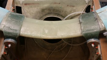
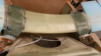
So late this afternoon I started on the gear by knocking out the first half of Long-EZ Plans Change (LPC) #128 that’s listed in CP-48.  It basically says that a few pilots had knocked their gear loose off the LGMAT tube and had to recenter the gear with a crowbar.  Then they ensured it stayed centered by placing flox in-between the gear tab and the 2024 aluminum gear mounting tab thus creating a thick flox washer between the two to keep the gear tabs in place both on the front & aft side of the gear.

Gear tab

Instead of trying to do this after the fact, if it ever came to it, and since I have no delusions of being the best pilot in the world or the fact that I won’t have a few hard landings, I thought it best to get this flox into these channels now while I still have good access.  For the record, I spent a good 10 minutes going over my build schedule and thought hard to see if I could come up with any scenarios where I would need to remove the gear for the rest of the build, and couldn’t come up with one.  So, in goes the flox!

I started by using my Perma-Grit tools to sand the glass gear tab opposite the landing gear mount extrusion so that the flox had something textured to bite into.

Sanded gear tab

To better keep the flox in place, I then cut up 4 plastic strips 1/2″ wide off an old package & wrapped them around the bottom of the gear tab (technically top since it’s all upside down) and butted up against the inside edge of each aluminum extrusion. I then taped the plastic strips in place to essentially create a “U” shaped channel.

Taped flox dam

Sanded tab & taped flox dam

I then whipped up some epoxy with fast hardener and made some wet flox and poured it into each U-shaped trough I created around each of the 4 gear tabs.  Obviously, this will only cover about half of the area, but by starting out with wet flox I know I’ll get good coverage in the hard to reach areas.  The “top” half will get a little bit thicker flox since the lower base half will be in place with the cured wet flox.

Wet flox in gear mount

Wet flox in gear mount

As the LPC #128 flox cured, I went to work on widening the 7/16″ diameter channel in the gear fairing foam pieces to 1/2″ in diameter.  I started with the 1/4″ round screwdriver looking Perma-Grit tool to widen the beginning of the channel out to about a 1/2″, then I switched to the 1/2″ round abrasive tool that you see in the pic below.

Sanding fairing channel to 1/2" diameter

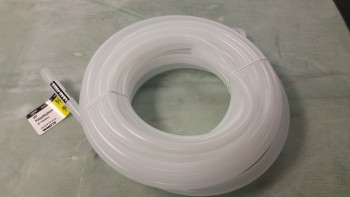
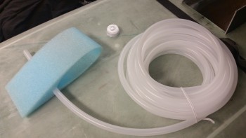
This is to allow for the emplacement of the 1/2″ diameter thinner walled plastic tubing that I picked up at Home Depot.

1/2"diameter plastic tubing

After sanding out the channel, I tested the 1/2″ diameter tubing and it fit great.

1/2" diameter tubing fits after sanding channel

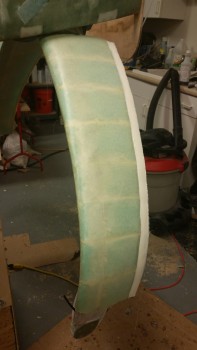
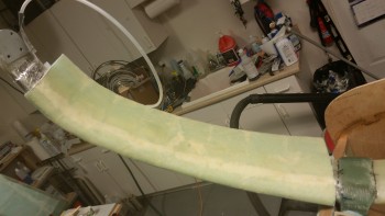
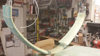
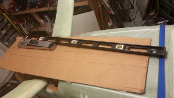
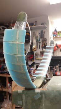
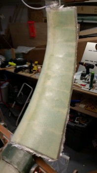
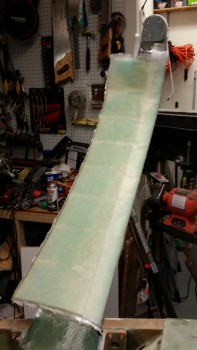
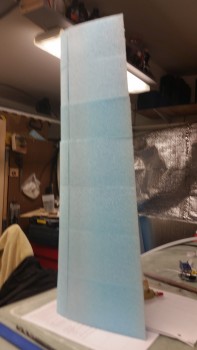
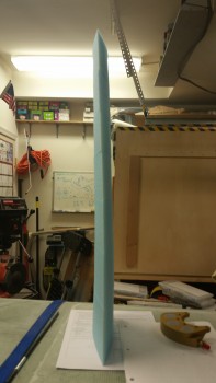
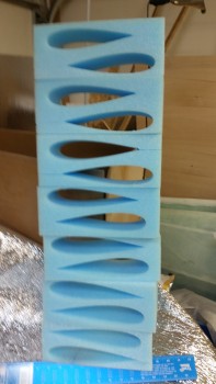
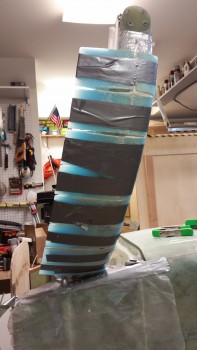
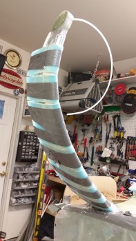
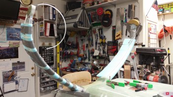
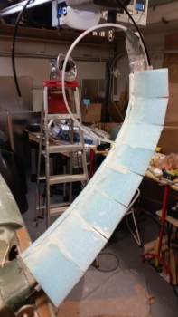
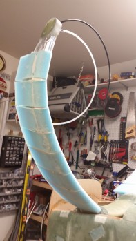
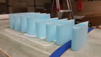
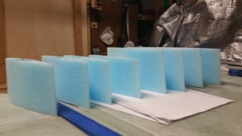
Just for fun & to see it’s “natural” shape, as I finished enlarging each gear fairing piece channel to 1/2″, I stacked them up on top of the fuselage.  Since the edges are very close to matching you can see a bit of a washout in the second pic.  BTW, I couldn’t get the very last fairing piece to balance without the whole tower crashing down.

Tower of gear fairing pieces

Tower of gear fairing pieces

Of course then I had to take a pic of the other tower I had created as I removed each foam fairing piece from its original block.

Tower of gear fairing carcasses

I then mocked up the first left gear fairing piece and once I figured out the starting point & marked it, I whipped up some old MGS 335 epoxy (to use it up) and made a bunch of micro with it.  Below I had just painted the inboard half of the gear leg with pure epoxy before I started applying the micro.

Wetted upper gear with epoxy

Jumping ahead, to keep the foam pieces tight on the gear leg I used duct tape to keep the two “halves” together.  However, since the tape I was using wasn’t sticking well, I carefully wrapped the duct tape around the TE and secured the tape back onto itself, on all but one fairing piece.  This method secured the foam to the gear leg just tight enough.

Left gear leg fairing pieces micro'd in place

Left gear leg fairing pieces micro'd in place

A couple other notes on the install.  First off, I would like to remind everyone that there are NO instructions that come with these gear fairings!  However, that being said, I will give HUGE props to Stephen James from Eureka CNC in that once I secured these fairing pieces tightly to the gear leg, they fit so spot on that the TE of the fairing pieces aligned so well that I had no need to use the clothesline pins that I spent a good 10 minutes looking for.  Very impressive.
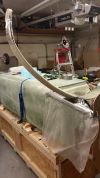
In addition, I mentioned previously that I needed to install these now since, unlike the Cozy version, these Long-EZ gear fairing foam pieces are cut in a single piece with a slit on the inner gear side.  However, on piece #5 I accidentally snapped it in half while sliding it into place.  It was then that I serendipitously realized that it was actually much better to mount these in 2 pieces since you can get more micro slathered on to all the surfaces.  This makes sense since instead of applying micro to the gear leg, then pushing it out of the way by sliding these pieces into place, if you simply install the front half in from the front, it captures the existing surface micro in place and keeps it in-between the gear leg and the foam fairing piece.  However, while there is a bit more room to get more micro in play on the aft side, by sliding the piece into place with the tube in the channel, the aft side is still a bit tricky to get all the micro in there for a really uniform application.  Thus, on the right side I will be cutting all the foam fairing pieces into 2 pieces before mounting them to the gear leg.
Left gear leg fairing pieces micro'd in placeLeft gear leg fairing micro'd in place

Here’s a wider angle shot of the gear legs showing the left gear fairing micro’d in place.

Left gear leg fairing micro'd in place

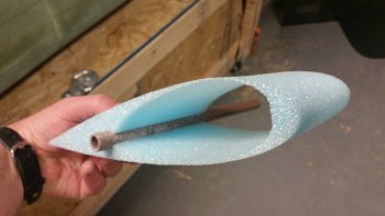
The shots below are a couple of hours later after I just carefully removed the duct tape securing the left gear leg foam fairing pieces in place.  You can see that I cut the ends of the 1/2″ channel tubing and ran another narrower black tube down the middle to test clearance and accessibility.  The tube works like a champ and I’m very happy with it.  BTW, the fast hardener on the MGS 335 kicks off much more quickly than the fast hardener on the MGS 285, so the micro in these pics was completely cured.

Left gear fairing attach micro curedLeft gear fairing attach micro cured

I then whipped up another batch of flox using MGS 285 with fast hardener and finished my flox gear washer mod IAW LPC #128 as described in CP-48.  I used slightly thicker flox this time since I didn’t have any dams to stem the flow of flox from running off the “top” half of each gear tab-extrusion gap.  You can also see that I had just spent a few minutes removing all the tape, plastic & errant flox from the “bottom” half flox application.

Here’s the new aft side flox “donuts.”

Main gear gap filled with flox

And the forward side flox gap fillers.

Main gear gap filled with flox

Tomorrow I plan on installing the right gear leg foam fairing pieces.  Once those are installed, I’ll start cutting all the UNI for the gear fairings.  I then plan on sanding down and laying up the left side fairing UNI on the underside of the gear leg.  I won’t be glassing the top sides of the gear fairings until after I flip the fuselage right side up.


Chapter 9 – Relief Tube Install

I started out today finalizing my research on relief tube installs.  I was checking out other builders’ sites to ensure I didn’t miss any good tips for installing the relief tube.

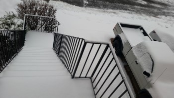
Although my class was canceled tonight due to the storm (as you can see in the pic below!), I then spent a few hours working on my course work.  I then spent another good hour+ shoveling snow.

Storm #2

After I got the snow cleared off my truck, I ran to the Aviation Department at Home Depot to pick up some 1/4″ OD for the relief tube and some 7/16″ OD tubing to embed in the gear fairing channel.   I found the 1/4″ OD tubing but they didn’t have any thin-walled 7/16″ OD tubing, so I ended up buying 1/2″ OD and I’ll see if I can make it work.

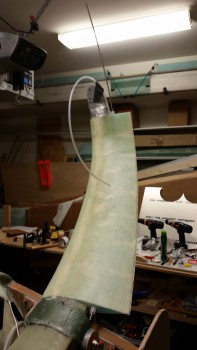
After getting back home, I mocked up the 1/4″ tubing on the left gear leg.  For the record, I did check out using Nylaflow for the relief tube but I didn’t like it since it’s just so darn stiff & unwieldy.  I’m glad I picked up the 1/4″ polyethylene tubing at Home Depot since it’s much more flexible than Nylaflow.

Prepping relief tubing for install

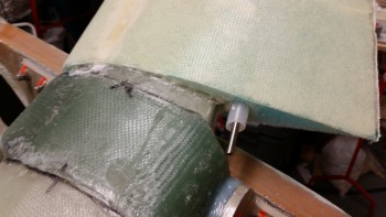
After a few more tweaks of the tubing on the left side gear TE, I then micro’d & glassed the relief tube in place using 1 ply of BID.  I then peel plied the layup.  Since this layup will be covered with micro and the gear fairing foam pieces, I went ahead and use some old MGS 335 epoxy & hardener that I had on hand.

Relief tube micro'd & glassed in place

Here’s a shot of the top side of the gear showing the relief tube glassed in place.

Relief tube micro'd & glassed in place

After a few hours under the heat lamp, the layup to attach the relief tube to the main gear TE was pretty much cured.  Here’s a couple pics of the cured layup.

Relief tube gear attach layup curedRelief tube gear attach layup cured

Tomorrow will be all about installing the gear fairings, possibly.  I say possibly because my fellow Long-EZ builder and Uber good friend Marco is planning on stopping by, weather & time permitting.  Still, I I do have time tomorrow I plan on getting the gear fairing foam pieces micro’d in place on the gear legs with the 1/2″ tubing in place, if it will fit.  Once the gear fairing foam micro cures, I’ll lightly sand & shape the BOTTOM of the gear fairing and then glass with 2 plies of UNI at a 30° bias in each direction.  Once I flip the fuselage back upright I’ll glass the top of the gear fairings.


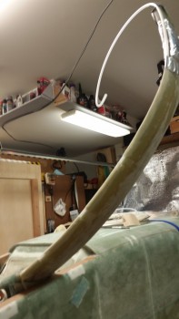
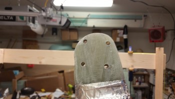
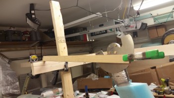
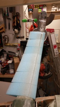
Chapter 9 … S-t-o-p-!-!-!

I’m taking a slight detour after I evaluated the gear fairing install requirements (see below).

I started out today by sanding down the sides of the axle mounting face on the lower right leg.

Right gear leg axle mount pad sanded

I then floxed the edges of the right lower gear leg axle mounting face and then mounted the right heat shield onto the gear leg.  Before mounting the heat shield I waxed the back side of it to make it more easily removable once the flox cures.

After I mounted the heat shield, I clamped on a straight piece of wood & dialed in the toe-in for a final time to let the flox edges cure to create a nice solid base across the entire axle mounting pad.

Toe-in reset with flox on axle pad edges

As I was contemplating installing the right side axle, brake assembly, and wheel, I figured I would check out the foam gear fairing I have on hand from Eureka CNC.   On the Eureka CNC website there’s an example of the gear fairing kit install, but it’s for a Cozy.  Well, the Cozy gear fairing foam pieces come in halves, whereas the Long-EZ gear fairings come as a single piece with a single slit across the thin underside of each piece.  If there’s a way to get the gear fairing pieces on or off without cutting them, I honestly don’t see it.  What this means is that I need to install the gear fairings before doing the final install on the axles, brakes, wheels & heat shields.

Test fitting gear fairing

Here’s another shot of the right side toe-in setting.  As for the gear fairing shown below, there’s one more piece that I wasn’t able set in place due to the thickness of the Fiberfrax. When I do install that last fairing piece I’ll have to reshape the foam on the inside of the fairing piece for it to fit.

Floxed axle pad edges & toe-in set

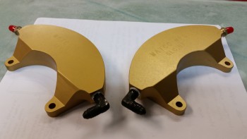
Once I finished my initial assessment on the gear fairing, I removed all of the left wheel & brake assembly off the left gear strut and then installed the 90° brake line fitting into the left brake caliper.

Fittings installed in brake calipers

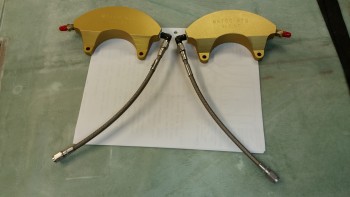
I then mounted the -3 Stratoflex stainless steel brake lines to check how they fit.

-3 stainless steel brake line connectors

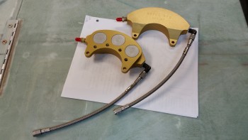
Then, probably more for my curiosity, I set up the brake calipers in the configuration that they would be in when installed on the gear legs as they are now on the inverted fuselage.

In mounting configuration (upside down)

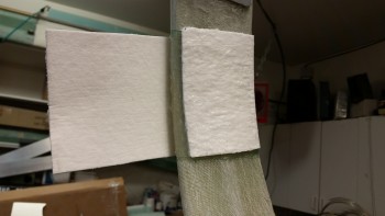
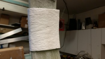
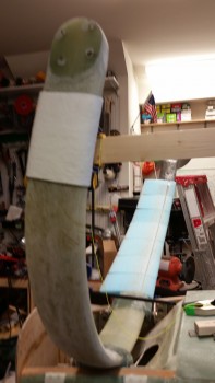
With the brake line fittings installed on both brake calipers, I then cut another piece of 1/8″ thick Fiberfrax 4″ x 10″.  I then test fitted the Fiberfrax piece on the left side gear leg.  I marked the area and then covered it with a good coat of RTV Silicone adhesive before putting the Fiberfrax in place.

Left gear leg Fiberfrax wrap

The pics below show the Fiberfrax set in place on the left gear leg.

Left gear leg Fiberfrax wrap

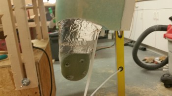
Left gear leg Fiberfrax wrap

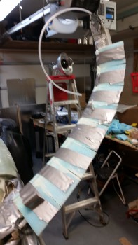
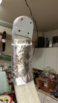
I then covered the Fiberfrax with foil tape.

Left gear Fiberfrax wrap & foil tapeLeft gear Fiberfrax wrap & foil tape

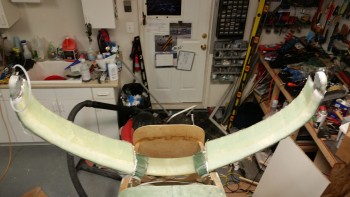
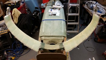
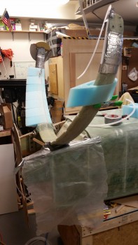
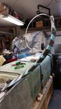
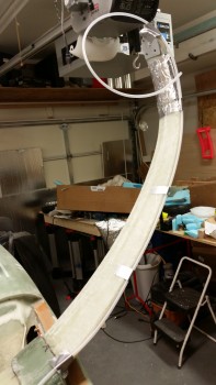
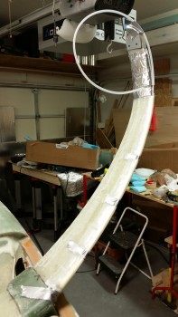
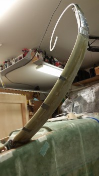
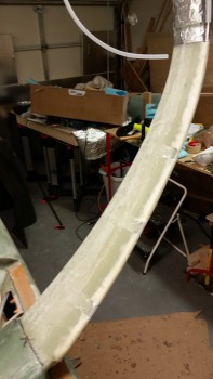
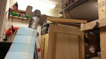
Although I don’t have the wheels installed, since I’m moving into a new phase on the main landing gear, I figured I would take a shot with the mini-“Straight Tower of Pisa” taken down.

Main gear progress continues

Tomorrow I’ll be on the hunt for 7/16″ OD thin-walled tubing to mount inside the gear fairing to allow for installing brake lines, relief tubes, etc.  I also need to determine the feasibility & cost of flaring the 3/16″ stainless steel brake line tubing I have on hand.  If it doesn’t seem doable in the very near future, or is too costly, I will most likely run Nylaflow from the aluminum brake lines ending in the hell hole to continue down the gear legs.