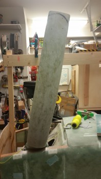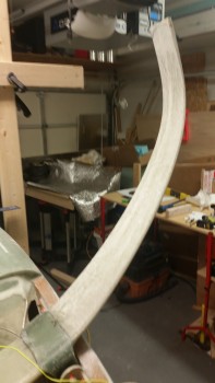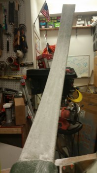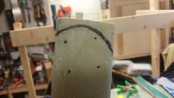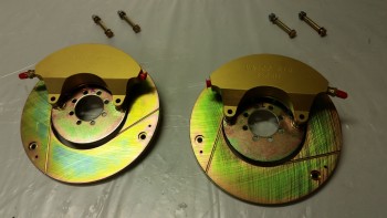
Chapter 9 – Left Wheel Installed!

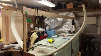
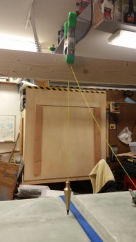
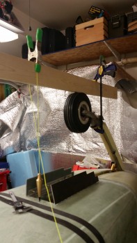
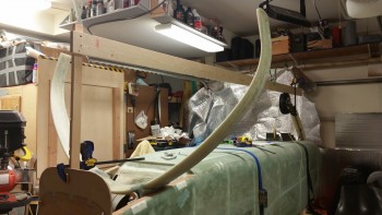
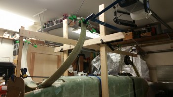
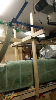
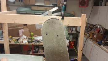
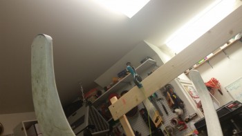
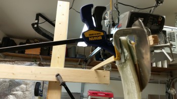
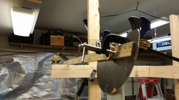
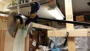
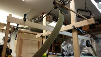
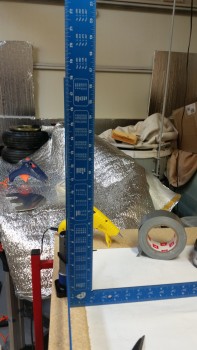
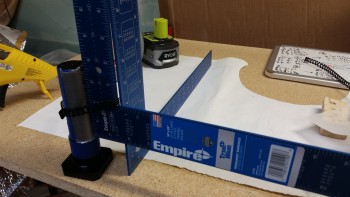
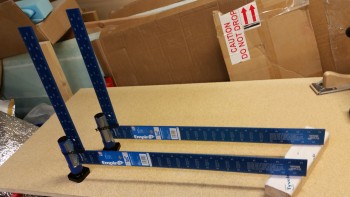
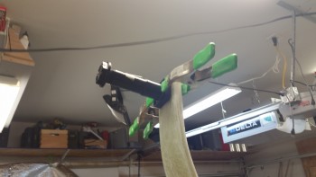
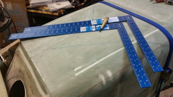
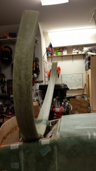
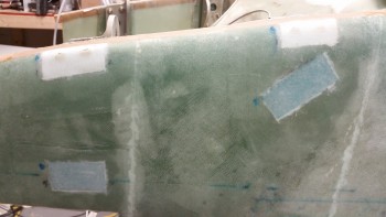
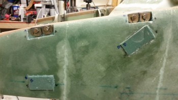
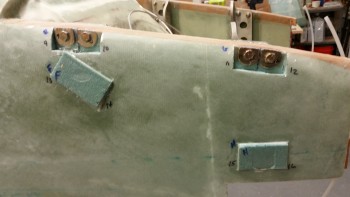
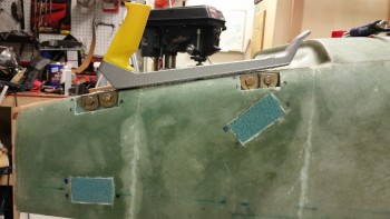
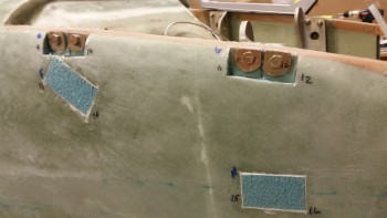
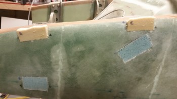
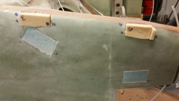
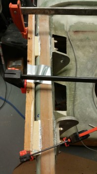
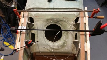
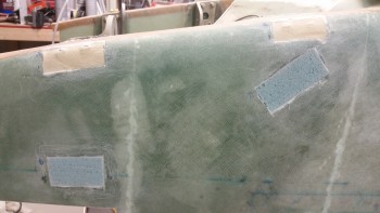
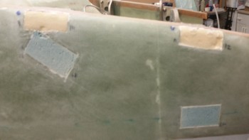
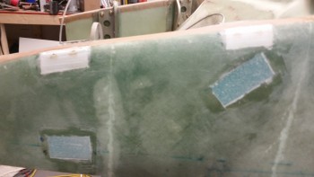
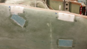
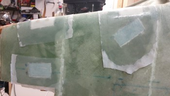
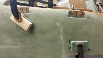
I thought I’d start off this post with a couple of pics showing my toe-in efforts from the top side looking down.  In the top pic you’ll note the 2 blue aluminum squares, which, of course, I didn’t even end up using.
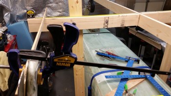
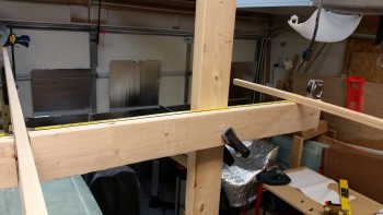
Toe-in right side

Toe-in left side

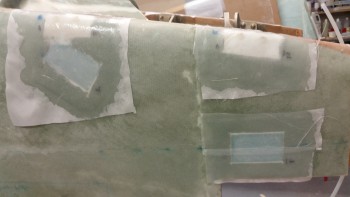
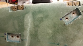
With the BID pads cured on each side of both lower gear legs, it was time to assess the damage.  I popped the heat shield off each side, and the first item of note was that I was going to have to remove the epoxy nubs that resulted from some of the epoxy squeezing through some of the heat shield bolt holes.  This wouldn’t have been an issue if my heat shields had stayed put and weren’t off from the marked bolt hole locations, since I would have simply drilled right through the nubs.

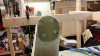
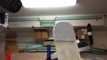
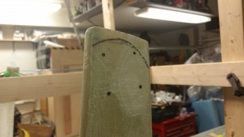
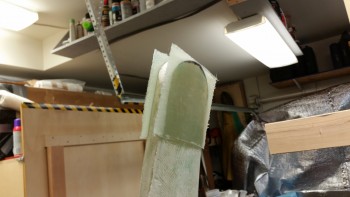
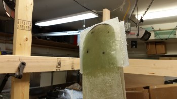
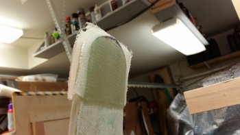
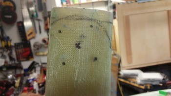
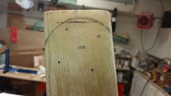
I decided to organize the pics in progression (vs. true chronological steps), at least initially, for each item.  Thus, below you can see the transformation of the left side outboard lower gear leg as I sanded & shaped the 9-plies of BID. [NOTE: What appears to be bolt holes drilled into the face are not holes, just areas where I removed the “nubs” I mentioned above.]

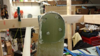
Let side BID pad

Left side axle BID pad trimmedRight side axle BID sanded

Here’s the back axle plate on the inside left lower gear leg.  The left side held decently, even though it was the side that gave me the most fits.
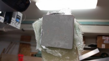
Left side axle back plate

Left side back axle plate - glass trimmedLeft side back axle plate trimmed

But the right lower gear leg was jacked up on both sides, although I didn’t realize the outboard side had any real issues until I went to mount the axle & heat shield later (more below).  Basically, you can see the flat spot in the middle which looks like the pupil of a cat’s eye, with the unpressed BID to either side.
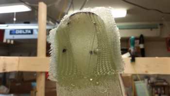
Right side axle BID pad

In addition, the back axle plate had slid way aft on me during the night.  The way the axle mounting bolts would align, there would be no other option than to knock the plate off & start over again.
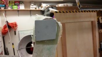
Right side axle back plate (misplaced)

Which is what I did.  Note that to the left is the flox base, which decided that it liked the grey primer better than the back axle plate.  Thankfully, since the surface of the plate was fairly smooth, it took one really sharp rap with a hammer & chisel to send the plate flying across the shop… but it was off!
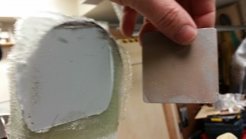
Right side axle backing plate removed

I then set my sights on mounting the left axle.  Using my previous marks as hole guides, I clamped the axle firmly in place with 3 C-clamps.  Then used the long 1/4″ bit to drill the holes.
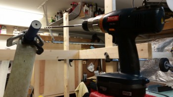
Left axle set for drilling

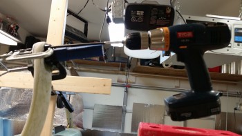
Drilling left side axle bolt holes

And here’s the results on the outboard side.
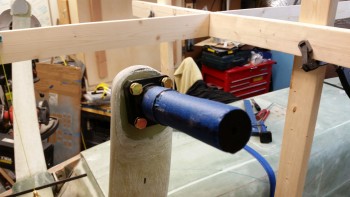
Left side axle bolt holes drilled

And the 4 AN4-22A axle bolt threads showing on the back side.  As per usual, I think AN4-20A bolts would be a better fit, maybe even just a tad shorter.
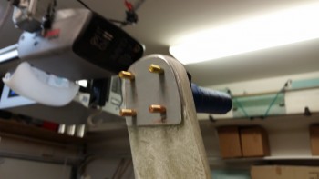
Left side back axle plate bolts

With the axle bolts drilled, I could determine just how much material needed to come off the lower gear leg to allow clearance for the brake caliper.  The plans throw around 1/16″ and 0.1″ as a number, but by using the Matco mounting & mocking up the brake assembly, I determined that the clearance between the Matco wheel/brake/axle mount and the brake caliper assembly is about 3/32″ (0.93″), so that’s what I used.

As you can see, I used a blue Sharpie to mark the areas that needed to be removed for brake caliper clearance.
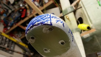
Trimming gear leg for brake clearance

And for the job, I took my ol’ mojamma belt sander out of retirement and threw a new 32 grit belt on it.  I say out of retirement because it took a good bit to dig it off the top storage shelf in the garage.
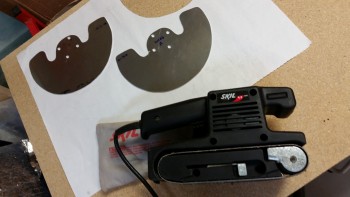
Mojamma sander for trimming gear leg

The belt sander worked like a champ!  Here’s the end result:
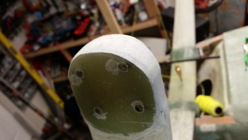
Left gear leg trimmed

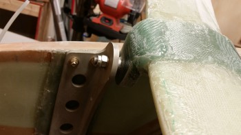
I then bolted on the axle along with the heat shield and the brake assembly.  The bolt fit was tight, and needed some persuasion, but it all went together fine.
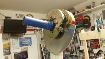
Axle & brake assembly installed

I removed the blue painter’s tape off the axle in preparation for mounting the wheel, but before I stuck the wheel on I wanted to use the heat shield to check the toe-in angle quickly before proceeding.  The toe-in was still right at 0.1″ difference between the zero measurement & the 24″ measurement.  With that bit of info, I was ready to mount the wheel & brake rotor.
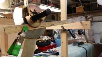
Final check of left side toe-in

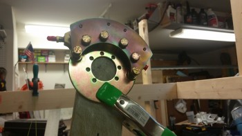
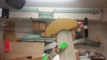
Here’s a side shot of the axle, brake assembly, and heat shield just prior to mounting the brake rotor.   The 6 bolts you see in a half moon shape encircling the top part of the axle had to be removed in order to remove the brake caliper assembly, which is a prerequisite step to allow the rotor assembly to be installed.
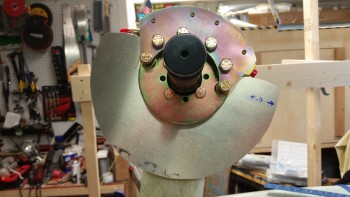
Side view of left axle & brake assembly

With the brake caliper assembly removed, I then mounted the rotor.  If you look at the outer circumference of the brake rotor you’ll note 3 screw holes.  These holes are what attach the brake rotor physically to the actual wheel.

You can also see the 1/2″ overhang of the heat shield beyond the outer edge of the rotor to protect the gear leg from the incredible amount of heat the rotor generates during braking ops.
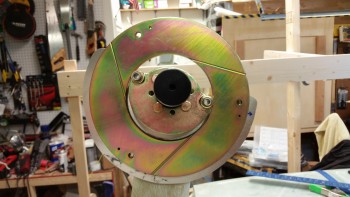
Caliper removed to install brake rotor

I took the shot below showing how close the brake rotor is to the heat shield.  It’s actually a little misleading though since when the brake rotor is bolted to the wheel, the space between it and the heat shield allows for plenty of clearance.
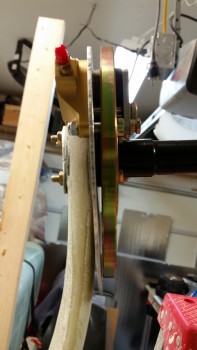
Rotor a little close to heat shield

Of course having never mounted one of these wheels before, I wasn’t sure what the rotor- to-heat-shield clearance would be, so I clamped the heat shield tightly against the gear leg to coax it to reside a little closer to the gear strut.  Also, in the pic below you can see that I remounted the brake caliper assembly around the rotor.  I torqued each end bolt of the 6 caliper bolts to 50 in/lb. and the 4 center bolts to 120 in/lb. as per Matco specs.
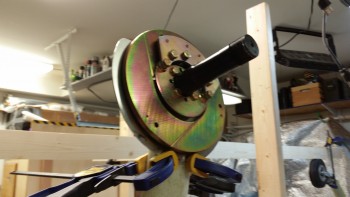
Caliper bolted back in around rotor

I then mounted the wheel, which in and of itself is an odd endeavor since the sealed axle bearing inside the center hub of the wheel is not allowed to rotate with the wheel, but has to be bolted in tightly so that it is secured to the axle –not spinning– and the wheel rotates around it.  As noted by Matco, this makes for a very tight install & the wheel bearings will break themselves in as they seat.  What this all means is that initially the wheel is pretty darn stiff in trying to get it to rotate.  Kinda weird, but hey, I figure Matco knows what they’re doing & I’m not going against their instructions.
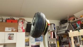
Left wheel & brake installed

With the left wheel mounted, it was time to start on the right side.  The first order of business was to clamp the axle in place & drill the 4 bolt holes (not shown).

After I got the bolt holes drilled & the confirmed the axle mounted fine, I then took the axle off & mounted just the wheel/brake mounting flange on the outboard side with 2 short AN4 bolts as guides.  I then clamped the popped-off back axle plate back into the correct position on the inboard side of the gear leg.
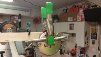
Drilling holes thru right axle back plate

Here’s a shot of the clamped back axle plate… and me!
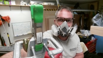
Selfie showing right back axle plate

I then drilled the bolt mounting holes in the back axle plate using the 4 axle mounting holes in the gear leg as a guide.  As I drilled each hole, I installed an AN4-22A bolt to ensure it fit.
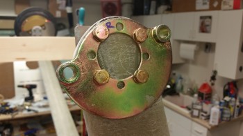
Right axle back plate bolt holes drilled

And here’s the back side axle mount plate with the AN4 bolts coming through.  Yeah, they aren’t perfectly straight, but I’m confident they’ll do their job.
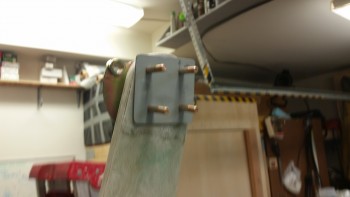
Right axle back plate bolt holes drilled

I marked the profile of the lower gear strut onto the 1/16″ thick back axle plate and then trimmed it down on 3 corners with a cutoff disk on the Dremel tool.  I then reattached it with flox since the forward edge of the gear leg underneath dipped down a fair amount since it wasn’t a part of the flox bed that was created when I originally mounted the back plate.  I used shorter AN4 bolts to clamp down the aft side of the plate, and used C-clamps to keep the front side of the back plate securely against the gear leg.
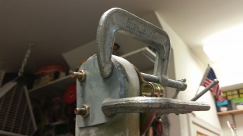
Right axle back plate remounted with flox

After mounting the left wheel, I discovered two important steps that I should have completed before installing the wheel:  1) Attach Fiberfrax to the gear leg since I can’t do it with the heat shield installed, and 2) Install the right angle brake line fitting, which I can’t do … you guessed it! … with the heat shield installed.

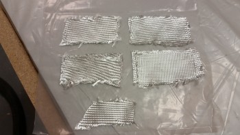
To remedy #1 on the right gear, I broke out the Fiberfrax roll.
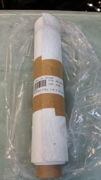
1/8" fiberfrax

I cut off a piece of Fiberfrax that measured 4″ x 10″, and then rounded up my RTV silicone tube & aluminum foil tape.
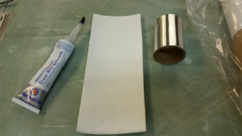
Fiberfrax prepped for install on gear leg

I test fitted the Fiberfrax & then marked the upper & lower edges, leaving about a half inch spacing on the top (technically bottom) for the foil tape to attach to the gear leg.  I actually did this after setting the wheel pant up next to the wheel & gear leg to get a generally idea of the amount of gear leg requiring cover.  I want enough Fiberfrax & foil tape to just exit out the top of the wheel pant and have it secured by the wheel pant mounting flange/fairing that will be part of the gear leg.

After marking it, I spread a film of RTV silicone onto the gear leg in-between the upper & lower marks.
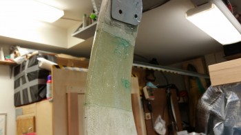
RTV silicone applied to right gear leg

I then attached the Fiberfrax to the gear leg.  Since this is 1/8″ thick Fiberfrax, I basically made a tri-fold application, with 1 layer outboard under the heat shield & 2 layers inboard on the backside of the gear.

As you can see, I’m very serious about taking measures to protect the lower gear strut from heat damage from the brakes.  In my opinion (ok, and RAF’s too) based on my research, not only should you use the heat shield to protect from the direct heat from the brake rotor, but if using big brakes especially (which I am) and tight fitting wheel pants (sounds like a country song, but I am doing that as well) then the Fiberfrax & foil tape helps protect the gear leg from the heat buildup in the wheel pant long after you’ve parked the bird and started drinking beer & telling war stories, even WITH venting of the wheel pants!
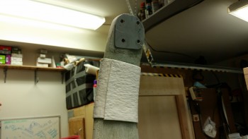
Fiberfrax set in place

Here’s a shot of the outboard single Fiberfrax layer.
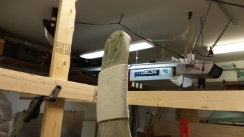
Fiberfrax set in place

I then wrapped the Fiberfrax with aluminum foil tape, which reading the package I was pleasantly surprised to see it rated for 250° F, which for the tape itself is pretty decent.
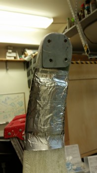
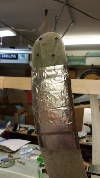
Fiberfrax covered with foil tapeFiberfrax covered with foil tape

With task #1 out of the way, now it was time to proactively accomplish task #2 on the right wheel.  I pulled an AN822-3 90° elbow out my tube fitting storage box and located my Permatex thread sealant equivalent of Locktite 567.
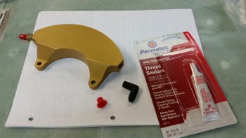
Prepping to mount brake line fitting

As per instructions, I left the first couple of threads dry & only applied the thread sealant 3/4 of the way around the pipe threaded side of the fitting.
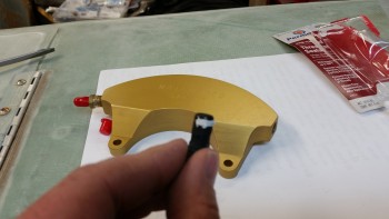
Thread sealant applied to fitting threads

(Oops…. apparently I forgot to get a pic of the fitting installed into the brake caliper assembly, but I’m sure I’ll get a shot of it tomorrow.)

I was planning on installing the second wheel/tire tonight, but when I double checked the toe-in angle I had wobble on the outboard axle mount surface since apparently I didn’t get enough clamp pressure when I was clamping the BID plies down during the toe-in setting.  It’s late & I would have to make a real ruckus to sand this down before adding a good bit of flox under the heat shield & then resetting the final toe-in, so it will have to wait until tomorrow.
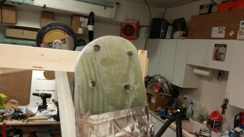
Right axle BID pad needs sanding

I did however take a minute to add blue torque seal to the left side wheel bolts.
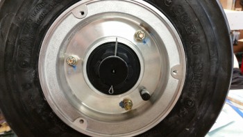
Torque seal applied to left side wheel bolts

Tomorrow will be all about finishing up the right axle, heat shield, brake assembly & wheel install.  I then plan on backtracking on the left gear side to install the brake line fitting in the brake caliper and Fiberfrax the lower gear strut.  Once those tasks are completed, then I’ll officially be done with Chapter 9, but of course I won’t call it until at least the brake lines & the gear fairings are installed.
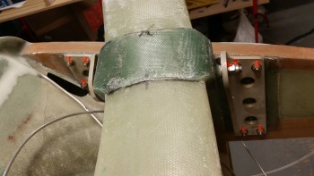
 

Chapter 9 – Mounting Gear Axles

I started out today by applying orange Torque Seal to all the gear mounting bolts in the hell hole.

Gear mount extrusions torque seal

I then mounted a 1×2 vertically on the firewall, offset 3/8″ so that I could then mount a horizontal 3/4″ wide board down the CL of the fuselage.  I originally was going to use my German aluminum long boards for the alignment board, but it wasn’t as straight as the 1×4 pine board I had on hand.

Mounting CL alignment board

Here’s a shot of the 1×4 CL alignment board.  As you can see, completing Chapter 13, the nose gear, allowed me to set the nose gear at just the right height & use it as a mount. Pretty darn handy!

Mounting CL alignment board

I set & verified the CL alignment board with a plumb bob at a few spots along the length of the board.

Mounting CL alignment board

Mounting CL alignment board

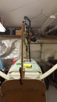
Here’s a shot of the installed CL alignment board.

CL alignment board mounted

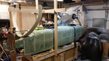
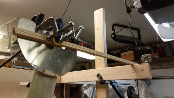
I then clamped my own version of the “Straight Tower of Pisa,” somewhat like my buddy Marco did.

Mini "Straight Tower of Pisa" erected

A shot of the left axle clamped in place, with a square attached.to it.

Configuring Toe-In

Another selfie for the FAA, right before I started in on all the major sanding of the gear bow.

Selfie for you FAA!

I sanded the left gear leg down to set the toe-in.

Gear leg sanded for proper Toe-In

Then, when I started checking the toe-in on the right gear, my measurement at the gear strut came out right about 0.12″ farther outboard than the left side.  I strung up my plumb bob over the center mark on the gear bow & confirmed that the gear was set about 0.12″ off center to the right.  Not sure how this happened since I had it dialed in while in Germany, but it was definitely an issue that I felt I should deal with.

After some thought, I decided to simply add 6 plies of BID on the exterior side of the left gear to move the wheel out about 0.1″.  Really, I don’t think being an 1/8″ off would cause any noticeable issues, but I want to keep the wheels difference from CL under 0.07″ or smaller.

Gear offset to right about 0.12"

After getting the initial toe-in set for the axles, I sanded down the entire gear legs for both the axle mounting BID gear pads, and the eventual installing of the gear fairing.

Final sanding of Gear Legs

Final sanding of Gear Legs

Here’s a shot of the right gear leg after final sanding.

Final sanding of Gear Legs

I then double-checked the lower gear leg markings . . .

Final markup of left gear leg

. . . and then initially trimmed the end of the gear legs.

Trimmed lower right gear leg

Here’s another shot of the trimmed gear legs.

Trimmed lower gear legs

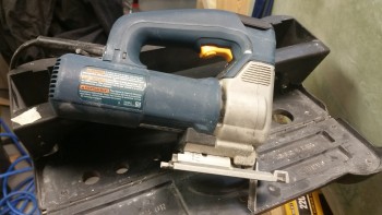
Here’s the specialized gear trimming tool . . .  ok, it’s a jig saw!

Lower gear trimming tool

I then test fitted the wheel assembly onto the end of the gear leg.

Initial check of wheel/brake assembly

Another shot of the wheel assembly test fit.  I still have some lower gear glass to trim, but this is a good start.

Initial check of wheel/brake assembly

Here’s a wide angle shot of the whole axle install effort.

Wide angle shot of axle install structure

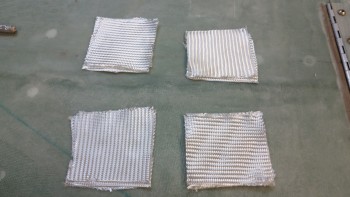
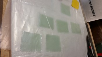
I cut the 3″x 3″ square BID plies for mounting the axles.  I cut 2 sets of 3 plies of BID for the right side, and then 1 set of 3 plies and another set of 9 plies for the left side.

3" x 3" inner & outer BID gear pads

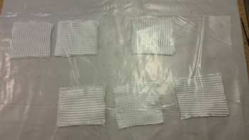
I then prepregged the BID pads in sets of 3 plies,

Prepregged lower gear leg BID pads

and wetted them out.

Wetted out lower gear leg prepreg BID pads

I then laid up the BID onto the lower gear legs.

Lower gear leg BID layups

Lower gear legs 3-plies BID (outboard right side)

Lower gear leg BID layups

Lower gear legs 3-plies BID (inboard right side)

Lower gear leg BID layups

Lower gear legs 9-plies BID (outboard left side)

Lower gear leg BID layups

Ok, I then let the epoxy cure for over an hour to set up to just tacky before mounting the axles to minimize the slipperiness & sloppiness of the wet BID. Well, it didn’t make any difference really.

To be honest, I’ve never been more pissed off during this build than this step right here.  If ever I should have followed my buddy Marco’s lead & taken a page out of his book and pre-drilled the axle bolt mounting holes it is here.  Trying to mount multiple components to a surface with multiple curves on BOTH sides with clamps is, to put it politely, stupid at best.  Hats off to other builders that have done it, but as I said it was truly the most infuriating thing I’ve tried to do on this build.  It also may be that the Matco axle base is narrower than the other brands, not sure, but it was about impossible (at least for me) to keep so many variables in check.

With the nearly cured glassed getting tweaked by the constant re-clamping of the axles, I eventually chucked them and simply used the face of the heat shields to determine toe-in. For any builders reading this, I would highly recommend this route.  That combined with just laying up the BID one side of the gear leg at a time to minimize variables and slop.

Setting toe-in left gearSetting toe-in left gear

I say this because after the sheer ass-pain with the left gear, then of course I spent well under 10 minutes on the right gear side mounting the heat shield and back axle plate.

Setting toe-in right gear

Setting toe-in right gear

As for the toe-in figures, my goal was to keep the difference between the 0″ measurement and the 24″ measurement between 0.1″ and 0.15″ to ensure that there is some toe-in, but not too much.  I hate to say it, but this is one of those layups that I’m crossing my fingers and hoping on, since it looked good after I was done clamping it all together, and 10-15 minutes later… but it’s late, I’m turning it and who knows what will greet me in the morning.

Setting toe-in for right & left gear

Tomorrow, I plan on pulling off the tape backed heat shields that are certainly in the slightly wrong position, finalize the clean up the bottom gear leg profile, and then mount the axles & wheels.


Chapter 9 – Prepping Axles for Install

I started today by doing some more research and analysis on the steps to install the axles to the main gear legs.  It’s interesting because just about every builder I know installed the axles and determined the toe-in angle close to the method described in the original plans, but to a builder they all did something significantly different than the way the plans detail the process.

Although I’m not casting doubt on the plans method entirely, I do want to optimize the process for installing the axles to the main gear & also in dialing in the toe-in angle, so some non-plans steps are most likely in order.  Admittedly, since I haven’t finalized the final flow of how the axle install process, I’ll knock out all the prerequisite steps and let the process reveal itself (said while sitting in meditation position . . . ha!).

In the shop I started by spending about 45 minutes filing the edges of the heat shields to finalize their shape and remove any heinous, finger-shredding burrs (see heat shields below).

I then determined the position of the left axle on the gear strut that allowed for the optimized placement of the brake caliper to minimize the removal of the bottom gear strut material.

Lower gear leg marked up - left side

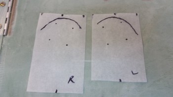
After setting the angle & position of the axle on the left side, I made up a template using tracing paper.  I then transferred the mirrored image of the left side axle placement onto the right lower gear leg.  Once I finalized and confirmed the placement of the axle on the right gear leg, I then made up a template for the right side as well.

These will be used IF I decide to follow the plans method which says to sand down the lower outboard gear leg to dial in the toe-in angle before trimming the gear leg or mounting the axle.  Clearly if I sand the lower gear leg, all my markings that I just finalized will be wiped out.  Thus, with my templates I can reapply my markings after shaping the gear legs for the toe-in.

Lower gear leg axle & trimming template

Here’s the right side lower gear with both the axle placement and lower gear removal markings shown.

Lower gear leg marked up - right side

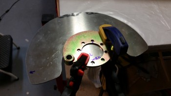
Once I finalized the positioning of the axle, I used the wheel mounting flange as a template to drill the 1/4″ mounting holes in the left heat shield.

Drilling Left side gear heat shield

Here’s the left heat shield mounting bolt holes drilled with the test fitting AN4 bolts installed.
Drilling Left side gear heat shield

And here’s the right heat shield mounting holes drilled.
Drilling Right side gear heat shield

A shot of both heat shields with the holes deburred & the sides filed smooth.

Drilled Left & Right gear heat shields

After finishing with the heat shields, I started work to attach the aluminum squares to the axles to determine wheel toe-in.  I wrapped the axles with tape to protect them from any out of control glue gunk.  I also used a zip tie to keep the square tight against the axle.

Hot gluing square to axle

I then used the free square to ensure that the first square I was gluing to the axle was …. yep, square.

Hot gluing square to axle

I then glued the second square to the other axle.

Squares hot glued to axles

Tomorrow I’ll borrow a page out my buddy Marco’s book and build a smaller version of his “Straight Tower of Pisa” to track the fuselage CL and dial in the toe-ins for each wheel assembly.  After I get the tower built, I’ll start the steps to mount the axles to the gear legs.


Chapter 9 – Main Gear Measurements

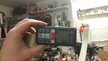
I started off today doing some final research on the threaded axle caps (p/n VA-106) from VANs Aircraft that makes installing Sam James’ wheel pants to Matco wheel assemblies doable without having to drill & tap the end of the Matco axles.  After speaking with the guys at VANs & confirming that I had the correct part, I ordered a set.

Down in the shop I started by torquing the main gear mounting bolts (AN6-80A) to 275 in/lb as outlined in CP 46.  For added strength I also added a couple drops of red Locktite to each bolt.

Main gear bolts torquedMain gear bolts torqued

I then spent over an hour leveling the fuselage and ensuring it was square & plumb.  As I started this process, the fuselage was really off as I tried to level it from side to side.  I finally did some investigating and looked inside the overturned fuselage.  It was then that I realized that the fuselage had slipped off on one side of the 2×6 sized board that I had it resting upon.  Once I corrected that little SNAFU, it made the process of leveling the fuselage much easier.

Fuselage off support

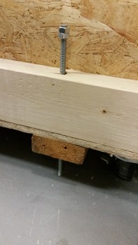
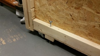
In addition to shimmying the fuselage to get it level, I also used the threaded rod leveling feet that I had mounted in each corner of the fuselage dolly for the first time.  They’re a bit narrow in diameter, but they definitely help.

First use of support bolts

Here’s another shot.

First use of support bolts

Once I ensured that the fuselage was level, I measured the distance between the main gear legs and points on the forward gear strut & the forward nose centerline.

Measuring gear strut alignment

I took 3 measurements from each gear leg, then shot 6 measurements to each leg from 2 different forward points on the nose & nose gear leg, respectively.  In the end, I had 9 measurements for each leg, 3 for each specific point.  I averaged each set of 3 numbers, determined the delta between the left & right gear for each set of numbers, then averaged those final deltas to get a final averaged aggregate delta.

When I originally mounted the gear I had determined that one side of the main gear was a 1/4″ farther aft than the other.  However, I was using a standard measuring tape when I originally mounted the gear.  When I used the laser measuring device this time, my delta between the left & right side gear legs came out to only 0.087″, which is fantastic as far as I’m concerned.
Measuring gear strut alignment

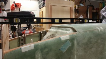
After I determined that the gear legs were a close match in both elevation (I checked when I leveled the fuselage by placing a long level across the gear leg bottom edges) and forward & aft, I then determined the WL of the center of the axles.

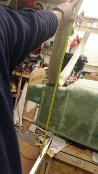
Since the longerons sit at WL 23.0, and the axle centers are at WL -22.0, then it stands to reason that by simply measuring 45 inches from the top of the longerons to the lower gear legs that I could determine the axle mounting location.  Now, there does need to be an adjustment as Marco points out on his blog since LPC#45 moves the 3/8″ bolt holes on the main landing gear mount extrusions up 0.4″, which isn’t accounted for in the WL -22.0 dimension.  Thus, this moving the bolt holes up 0.4″ makes the new height of the gear at WL -21.6.

So when I measured the height of the center of the gear axle, I subtracted the 0.4″ to make the dimension 44.6″ up from the longeron (when the fuselage is upside down) to the center of the gear axle location.

Measuring gear strut height & waterline

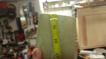
Here’s a shot of the approximate center point of the axle at 44.6″ below the longeron (at WL -21.6).

44.6" equals axle center point

When I marked the left side gear leg, the 44.6″ mark was 1.3″ away from the end of the center of the gear leg.  I really wanted another 0.2″ inches, and then lo & behold I realized that the other side of the level pressed against the longerons had slipped a bit.  Once I wedged the level back tight against the longerons, I remeasured the left side and was able to reclaim my 0.2″ so that the 44.6″ mark was at 1.5″ above the bottom of the gear leg (below with the gear upside down).

1.5" down equals axle center point

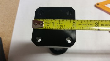
I wanted the 1.5″ gap between the bottom of the gear leg and the center point of the axle since the axle bases, as shown below, are 2″ square.  Since a half inch provides room to remove some of the lower gear leg for clearance for the Matco brake calipers.

2" axle base

Here’s the 1/2″ mark on the left gear leg.

1/2" down equals axle edge

Below are the Matco axles clamped into place to test the fit, both on the left & right gear leg.

Test fitting left axle mountTest fitting right axle mount

In preparation for mounting the axles to the gear legs, I made a run to Home Depot today and picked up some aluminum squares and a plumb bob, as you can see in the pic below.

Aluminum squares & plumb bob on hand

I then went back to work on the main gear wheels.  The first thing I needed to do was torque all the bolts to ~99 in/lbs (8.5 ft/lbs).

Main gear wheel bolts torqued to specs

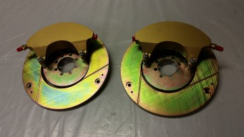
I then disassembled the brake assemblies in order to isolate the brake disk mounting flange that I will need to mount the wheel assemblies onto the axles.

Wheel brake assemblies

I first removed the 2 longer bolts from the outside edges of the calipers.

Disassembling brake assemblies

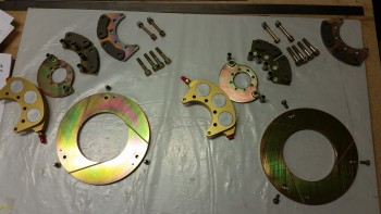
I then removed the 4 large diameter bolts in the center of the caliper assembly, and laid out all the parts as a sort of inventory & acquaintance of the parts, but specifically to ensure the brake pads looked ok & weren’t cracked (which happened to my buddy Marco).

Wheel brake assemblies disassembled

Tomorrow I plan to mount a few 2x4s to the fuselage dolly as a quick frame to help assist in measuring the toe-in for each wheel.  I’ll also be determining and aligning the wheel assemblies to the fuselage centerline.  Within the next few days I plan on having the wheel assemblies installed on the lower gear legs.


Chapter 9 – Spin… that… wheel!

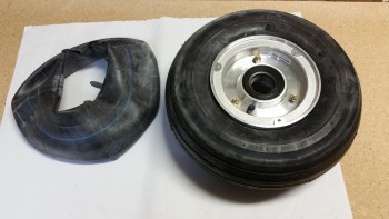
Today I got the tire & tube mounted to the other  wheel.  Since I was trying to get at least this one thing completed for the build before I headed out to dinner, I didn’t balance the yellow stripe on the wheels, so I guess that will somehow either make the plane fly crooked or the wheels not in synch!  Although I try not to sweat the small stuff or be too anal as to add unneeded time to the build, had I noted the position of the yellow stripe, I would have mounted the tires symmetrically.

Just like the previous wheel I inflated newly mounted tire to 50 PSI.  I’ll watch the tire pressures for about a week and make sure they sustain 50 PSI, and when I’m sure that they’re are no leaks, I’ll inflate both tires to 70 PSI.

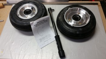
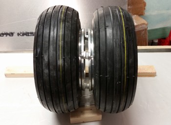
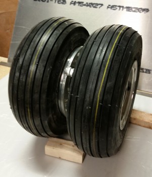
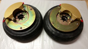
Here they are, my officially mounted tires!  Again, I’m running Lamb 11 x 4.00-5 tires on Matco W50LT wheels.

Both tires & tubes mountedWheels with tires mounted

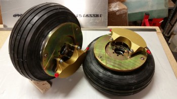
I then added the brake assemblies to the wheels for these pics.  I’ll still have to torque the bolts to the appropriate specs as I do final mounts on each of the wheel components, so the only actual torque job on my immediate list is the main wheel halves.

Brake assemblies mounted to wheelsWheels, brakes & tires

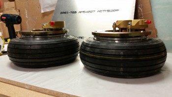
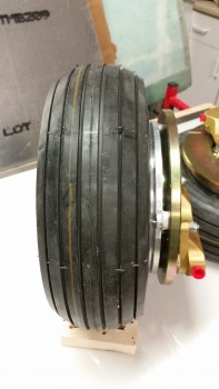
Finally, here’s a couple shots showing the width & depth of the brake assembly mounted to the inboard of each wheel.

Wheels, brakes & tiresWheel & brake assembly

Again, tomorrow is Superbowl Sunday so although there will be a fair amount of tours of my EZ-building shop, I highly doubt if I’ll get any work done on the plane.


Chapter 9 – Main Gear Install

Due to prepping for a Superbowl Party that I’ll be having at the house on Sunday, I didn’t get any work done on the plane yesterday.

Today I mounted the extended firewall to the aft fuselage early on in the day.

Extended firewall remounted

Here’s a shot showing approximately what the new profile of the aft fuselage will be when the plane is finished.  Of course this is upside down, but clearly the width & bulk of the fuselage will be extended aft to create more of a “boat” shape vs. the traditional swoop of the old P-51 style inlet.  In short, my Long-EZ will have the same profile as one that has a NACA scoop intake.
That being said, I will have a 3″ round air scoop, somewhat like James Redmon has on his Berkut 13, that will run from aft of the landing brake and slowly meld into the bottom hell hole area so that it should (still in design phase) dive aft into the firewall and flow into the lower cowling skin.  Thus, I guess my EZ will look a tad different than all the NACA-scooped EZs.

Checking future bottom fuselage lines

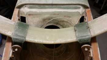
I had pulled the main landing gear bow out a few days ago, but just this evening –with the help of my buddy Greg– I sanded down the gear legs for the eventual adding of the gear fairings, and then (re)mounted the main landing gear bow back onto the fuselage.

Main landing gear remounted

Although there was the usual fight to get the bolts in, I was pleased that in the end, after a few years of the gear being off & redoing the washers on the mount extrusions, that the gear fit back into the mounts with only a little bit of banging with the hammer required.
Main landing gear remounted

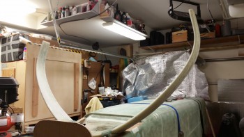
Here’s a vertical shot of the main gear legs.

Main landing gear remounted

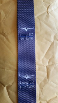
I thought I’d add this pic to show you all what the battery strap for securing the main battery in place will look like.  This is an initial sample that strapworks.com sent me to finalize the custom strap that I’m having them make for me.

Battery mounting strap test strip

Tomorrow will be a light build day since my buddy Greg is over & tonight will be a late night drinking beer & swapping war stories in front of the Chimenia on the deck.  In addition, I’ll be doing the final preps for the Superbowl Party, which of course will consume all of Sunday.  I did receive my tire inner tubes so I plan to mount the tire & tube onto the other wheel.  Finally, I bought some lumber for creating a frame around the gear legs to allow me to position the wheels on the gear legs, align the wheels to each other and to dial in the toe-in correctly.  I’ll get the lumber unloaded & situated in the garage so I can start in hot & heavy on Monday installing the axles onto the gear legs.


Chapter 9 – This & that… etc.

I got a late start today so I didn’t get nearly as much done as I wanted to tonight.

I started out today by removing the peel ply from the main landing gear bolt swap foam insert layups.

Final clean on main gear bolt swap layups

I figured at some point I should add a selfie for the FAA, so here it is!

Yes, I'm building it!

After cleaning up the aft fuselage landing gear bolt layups I then marked up the lower firewall to cut for adding the extension.

Marking up lower firewall for extension

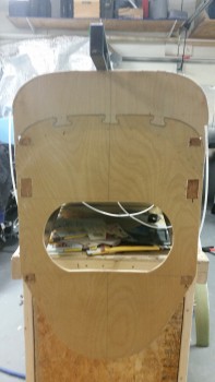
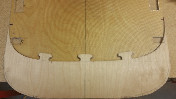
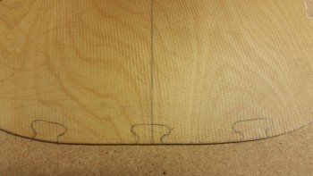
I then marked the lower firewall to cut the matching “puzzle piece” interfaces with the wood extension piece.

Marking up lower firewall for extension

After cutting the “puzzle piece” notches in the lower firewall, I then test fitted the firewall extension.

Test fitting lower firewall extension

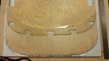
I then floxed the firewall extension piece to the lower firewall & glassed with 1 ply of BID.

4" firewall extension floxed & glassed

And peel plied the lower firewall extension addition.

Firewall extension layup peel plied

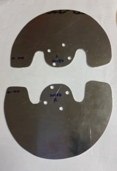
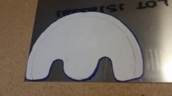
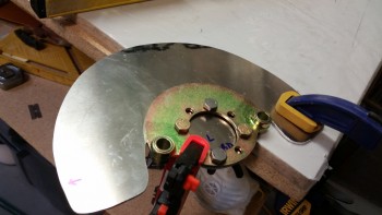
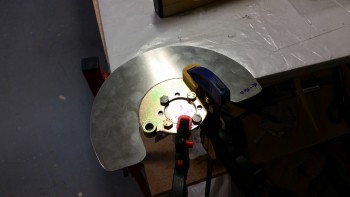
After glassing the firewall extension I then traced the gear leg brake disk heat shield template onto the 0.09″ thick 6061 Aluminum plate for cutting.  Again, I’m using 6061 Aluminum as a heat shield since it’s much more corrosive resistant than 2024 aluminum, and in this application, strength is not really required.
0.09" 6061 aluminum marked for cutting

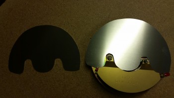
I then cut out the heat shields using my jig saw.
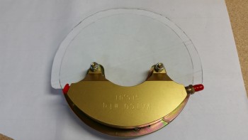
Heat shields cut from 6061 aluminum

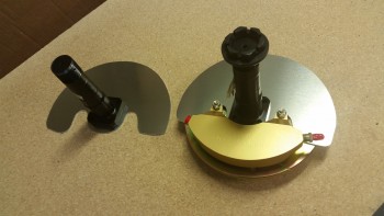
I then test fitted the axle mounting flanges on the heat shields.  So far, so good!

Axles mocked up on heat shields

I pulled the gear out tonight to clean it up & then mount it, but then I realized that I needed to sand the entire gear bow in preparation for attaching & glassing the gear fairing to it.  It was too late to undertake a big sanding job, so I’ll do it tomorrow.  I also plan to drill & tap a hole on each axle end so that the axles are prepped for the eventual mounting of the wheel pants.


Chapter 9 – Gear bolt washer swap complete

I started off today by removing the clamps from the upper gear mount bolt foam covers that I micro’d & clamped into place last night.

Cured bolt trough foam inserts

Here’s a shot of the right side upper gear bolt foam inserts micro’d in place.

Cured bolt trough foam inserts

I then used the Stanley Surform “cheese grater” to knock down the excess foam.

Sanded bolt trough foam inserts

Again, right side after “cheese grating.”

Sanded bolt trough foam inserts

I then did something that I rarely do on this build: I grabbed some of the ton of excess urethane foam I have on hand and cut blocks to fill in the lower bolt holes.  Honestly, with as little foam as there is at the lower edge of the bottom longerons, I could have probably just as easily floxed the existing corners & called it a day.  But since this edge will have more foam added to it to fill in the space for the aft fuselage fill-in/lowering to match the 4″ lower firewall & cowling, I went ahead & filled these bolt troughs with foam.

Lower bolt foam inserts

Right side lower bolt troughs filled with urethane foam.

Lower bolt foam inserts

I then micro’d the urethane foam filler pieces into place in the lower gear bolt troughs along the lower aft fuselage edge.

Micro'd lower bolt foam inserts

I then used 2 tape-covered pieces of wood to cover the freshly micro’d in place urethane foam inserts and clamped those across the aft fuselage (hellhole).  Here’s the left side fuselage.

Clamped & micro'd lower bolt foam inserts

Since I had one extra small piece of foam all by itself on the lower right side I needed to give it a little extra attention, so it got its own clamp (bottom of pic).

Clamped & micro'd lower bolt foam inserts

And a wide angle shot of the clamped urethane foam inserts.

Clamped & micro'd lower bolt foam inserts

While the micro cured I went to work on cutting the firewall extension piece.

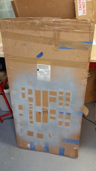
I pulled out the box containing my 6mm (1/4″) Finnish Birtch plywood.  The plywood box being easily spotted… recognize it?  It’s the box that I primed all the 2024 aluminum extrusions for the wings & CS spar.  Ah, memories!

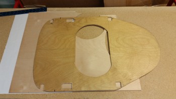
Anyway, I pulled out the second uncut 24″ x 48″ sheet that I still have left over from my original order of 2 sheets, but then found the remaining piece left over from when I cut the original firewall.  This piece was plenty big enough from which to cut the 4″ firewall extension.

Finnish birch plywood box

I marked 4″ up from the bottom edge of the scrap Birch plywood sheet, and then placed my existing firewall in place with the vertical edge aligned flush with new plywood edge & the firewall bottom edge aligned with the 4″ line on the plywood.

Determining 4" plywood extension

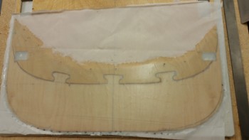
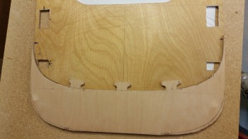
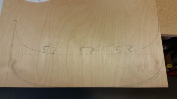
I then traced the bottom of the firewall in relation to the marked 4″ line across the plywood piece, and then again along the very bottom edge of the plywood piece.  The latter will be the new bottom edge of the firewall.  I then made 3 puzzle piece styled locking tabs to help lock the new 4″ firewall extension in place when it is attached to the bottom of the existing firewall.

4" plywood extension marled up

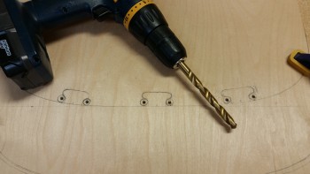
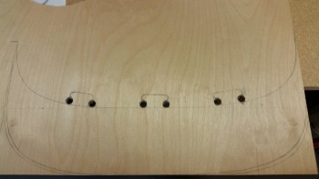
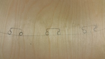
Here’s a closeup of the “puzzle piece” tabs.  I grabbed a 27/64″ (.421″) drill bit and traced the bottom edge of it to the side of each puzzle piece tab to mark the drill points that will make up the compound curve of each locking tab side.

Radiused locking tabs marked for drilling

I then drilled a smaller pilot hole for each circle I just marked.

Starter holes drilled

Loaded up the mojamma 27/64″ bit . . .

Ready to drill the big holes

. . .  and drilled the holes to make up the compound curved edges of the puzzle piece locking tabs.

Locking tabs' side edges drilled

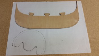
I then used my jig saw to cut out the rest of the 4″ lower firewall extension piece.  I would have preferred to have a finer jig saw bit, but since it will all get covered with glass anyway, I wasn’t too concerned about a slightly rougher edge.

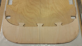
Here’s the new firewall extension piece mocked up along the lower edge of the existing firewall.

Mocking up 4" firewall extension

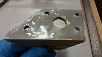
In the pic below you can see the paper template that I will finish tweaking in order to cut out the 0.09″ thick 6061 aluminum heat shields for the lower gear legs (as per CPs).  I’m using 6061 vs 2024 since it is more corrosion resistant, and that will be a definite benefit in the lower gear & wheel well environment.

4" firewall extension cut out

Here’s the lower gear heat shield test fitted onto the wheel brake assembly.

Determining brake heat shield shape

After all my ancillary shenanigans above, the micro on the lower urethane foam inserts was at least 80-90% cured, so I proceeded with the final glassing of all the foam plugs covering the main gear mount extrusion bolt heads.

I sanded down the urethane foam inserts to match the contour of the lower fuselage edge.  I have to say that I haven’t worked with urethane much, and it is definitely SOFT, so it requires a much more delicate touch than I admittedly used in sanding the inserts to shape.

Sanded lower foam inserts

Sanded lower foam inserts

After locating & cutting my scrap BID pieces to cover the foam inserts, I then micro’d all the foam pieces.

Foam micro'd for layups

Foam micro'd for layups

I prepregged 6 pieces of 1-ply BID, laid them up over the foam inserts & then peel plied all the freshly laid up glass.

Peel plied glassed gear bolt foam inserts

Peel plied glassed gear bolt foam inserts

This completes the main landing gear mount extrusion bolt washer swap!  Although it essentially added 3 days to the build, the piece of mind it provides is well worth it.  I’m very happy that I did the swap and also very pleased with how it turned out.

Tomorrow I’ll be working a lot various components in prep for the gear install: cutting the bottom of the existing firewall & floxing/glassing the 4″ extension to it; cutting out the heat shields from the 0.09″ aluminum sheet; leveling & truing the fuselage; cleaning up the gear bow in prep for mounting; shaping the inboard wheel pant support bracket, etc.


Chapter 9 – Washer Swap Part 3

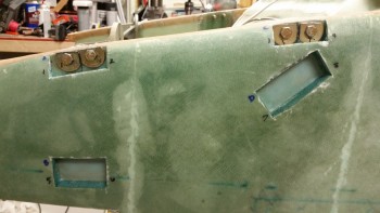
I started out today by making some noise!  I was able to quickly get the 1/4″ mounting bolts out of the left side of the aft fuselage, leaving some rather securely embedded washers in the process.  I tried to quickly remove the washers but they weren’t budging, so I left them for a bit while I removed the right-side bolts.

Upper left bolts removed

All was going well until I got to literally the last bolt to remove.  I have to say I’ve always been impressed with the size & strength of the aircraft grade MS21042-4 nuts, but one huge disadvantage is that if you make one good slip up with the wrench on a very tightly installed bolt, and POW! . . . It’s stripped!  And that’s exactly what happened with this last nut/bolt that is one of two –including the other side– that are pretty difficult to reach.

Well, I messed around with this *!&$#@ nut for almost half an hour to no avail.  I pulled out the whole armada of tools that I have in the shop … again, with no avail.  Thus, in my overwhelming need & desire to win out over an inanimate object (and believe you me, this sucker was INANIMATE!) I figured since I had loosened it up even by the slightest degree, that it had to come out.  But, just about as far down on the inboard side in a “V” channel as you can get, there was just no way to forcibly remove the nut & pound the bolt out.  I was going to have to attack it from the accessible outboard side.

I taped up the inside of the upper bolt trough with aluminum foil tape (I took a pic but it turned out really blurry) to protect the foam from the sparks.  As you can see below, I missed a spot.  Nothing like the smell of burnt foam in the morning to wake you up!  I spent a good 5 minutes with the Dremel grinding off the bolt head, and then another 15 minutes getting the remainder of the bolt, with nut attached, removed.

Burning foam! (Unfortunately)

As I was using a center punch from the outboard side to dislodge the jacked-up bolt, I quickly realized that it wasn’t going without a fight.  If it was departing the airframe, then it was going to bring the lower forward landing gear mount extrusion with it.  I don’t know why, but this bolt was seemingly fused to the gear mount extrusion bracket.  I eventually let it have its way by unbolting the 2 top bolts to get the whole extrusion bracket out of there.  Now, this was after creating about a 1″ gap between the interior side wall (15-ply BID pad mounting base) and the outboard mounting surface side of the extrusion.  With this gap, I snuck in my small German hack saw and cut the bolt in half… another solid 5 minutes down the drain!  Once the bolt was cut in two, I drove the whole assembly back towards the side wall to get enough clearance to free up the bolt that at this point was gouged & stuck into the aft side of the GIB setback (you can see the divot in the pic below).

Left forward lower gear extrusion removed

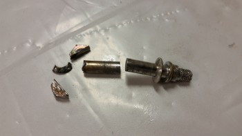
I then removed the gear mounting bracket with the remainder of the Bastard Bolt from Hell! still stuck in the bolt hole.  Even after all this, it still took some really sharp blows with the center punch to get this damned bolt removed from the bracket!

Removed forward landing gear bracket

Here’s the skeletal remains of the Bastard Bolt from Hell! after I dismembered it!

Bastard Bolt from HELL!

Thankfully, it took only about a minute to remove all the scorched foam & clean up the bolt trough.

Foam cleaned up from "the scorching"

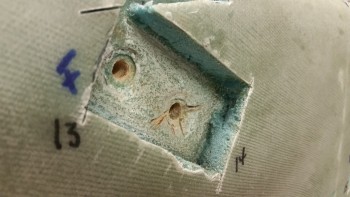
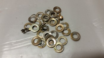
And here are some more casualties of war.  I’m still not sure why I mixed up the AN960-416L washers for the standard ones, but again, that completely solidifies my decision to spend a few days swapping out these main landing gear mount attachment washers.

Casualties of war!

Back to the “peaceful” side of the fuselage, I spent a few minutes (I should add the words “longer than needed” here!) removing the embedded washers.  To keep with the slog of a day that I was apparently mired in (ha!) I bent the tip of scribe trying to get these damn embedded washers out!  I finally resorted to using a 1/4″ diameter cylindrical punch pin to insert into each washer just enough where I could then push the pin to one side and pry out the washers.

Old washers removed

I employed my new found trick on the right fuselage side and removed the washers handily.  I then embedded Saran wrap in the aft holes in prep for flox, but in the forward holes I wrapped the Saran wrap with electrical tape to have a dark identifying marker for the bolt hole since I would have to drill the forward bolt holes from the outboard side with no mounting bracket holes as a guide.

This wasn’t just on the right side where I had the issue with the stuck bolt, it was simply a matter of access to drill the holes on the inboard side of the fuselage.  The upper mounting bolt holes on the forward main gear mount extrusion simply are located higher than the aft lines of the GIB seat back.  Unless I was using a flexible drill bit attachment, it was physically impossible to get access to the inboard side bolt holes to drill them.  Thus the dark protective plastic in the forward upper bolt holes.

Right side upper bolt holes filled with plastic

I then grabbed a couple of strips of the scrap BID that were left over from the nose layup I did a couple of weeks ago.  From the BID I made up 2-ply BID pads to prepreg & layup in the upper bolt access troughs cut into the side of the fuselage. I also added a 1-ply piece of BID to repair the punctured seat back from when I removed the Bastard Bolt from Hell!

2-ply BID prepreg for upper bolt hole troughs

Below are the left & right shots of the laid up 2-ply BID pads over flox to reset the “floor” of each bolt trough back to level after the damage of the original bolt heads & washers getting embedded too deep in the surface.  As I’ve stated before, this damage was part & parcel to having the bolts installed with enough clamping pressure to keep the landing gear mount extrusions mounted securely.  Yet another reason I’m really pleased to be performing this washer swap.

Upper bolt troughs floxed & glassed

Upper bolt troughs floxed & glassed

While the flox & glass was curing I went to work to knock out some ancillary tasks.

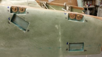
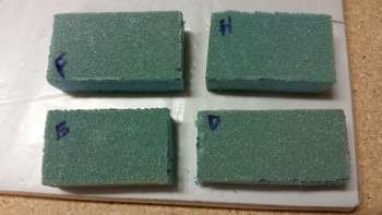
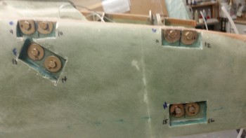
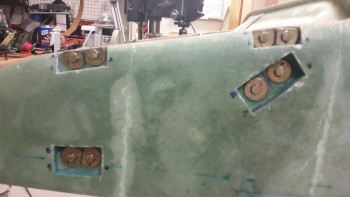
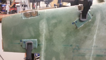
First, I grabbed some spare 3/4″ thick Divinycell PVC foam & cut them into blocks to match the dimensions I had measured earlier for each of the upper mounting bolt troughs cut into the side of the fuselage.  As you can see, they’re identified with the letter designator that I labeled each bolt trough with.

I’m not exactly sure how I’ll deal with the lower gear mounting bolt troughs that I opened to expose the bolt heads along the very bottom longeron edge of the fuselage.  I’m not really that concerned about the aesthetics of these lower bolt-access troughs because they will reside directly under the newly mounted fuselage sidewall lower extension foam that I will be adding to fill in the aft fuselage to account for a 4″ lower firewall.  Again, this is to match my Carbon Fiber engine cowlings that were designed by Mike Melvill & fabricated by Feather Light.

Upper bolt trough foam insert covers

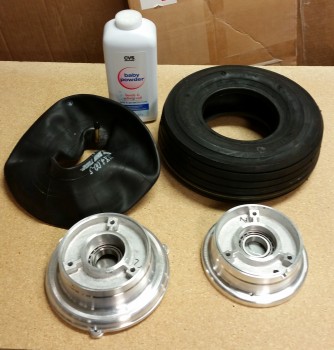
With the upper bolt hole foam inserts cut to size, I then started on installing the tires & tubes to the Matco main gear wheels.

Tube & tire install

And here’s the end result.  One wheel with the tire & tube installed, and yet another casualty!  On try #1 I followed Matco’s directions by adding about 10 PSI of air into the tube when it was installed in the wheel before bolting both halves of the wheel assembly back together.  This made the process nearly impossible, even with clamping both halves together.

So, round #2 I followed the sage advice of Frank Sinatra and, “Did it my way!” by not adding any air, clamping the tire down to ensure that none of the tube would get pinched, then bolted it together and filled ‘er up to about 50 PSI (70 PSI is max on this tire/tube combo).  Voila!  It worked!

Note that each time I did use talcum/baby powder to reduce the friction of tube going into tire.

Also, I will order a couple more tubes from ACS later this evening.

"Practice" tube & installed tube/tire

After messing around with tube & tires, I spent a couple of hours making a few phone calls before returning back down to the shop.  The flox & BID in the bolt troughs were nearly completely cured, so I pulled the peel ply . . .

Upper flox & 2-ply BID cured

. . .  and then re-drilled the bolt mounting holes.  I have to say that I’m glad I used the dark plastic material for the inserts since I could see where to drill the holes on the forward bolt holes.

Bolt holes re-drilled

After trimming the upper aft AN970-4 washers to fit, I then vacuumed out the troughs & then mixed up some wet flox using fast hardener.  I spread a good bead of wet flox on the forward gear mount extrusion and installed it.

Floxed lower forward gear extrusion

I then started on the forward extrusion after mounting the bracket back into place, and mounted all the remaining bolts & washers after applying wet flox to inside face of the AN970-4 washers.

R upper gear bolts & large washers installed

Here’s a shot of the bolts & new large washers installed with wet flox on the left side of the fuselage.

L upper gear bolts & large washers installed

After I ensured ALL the main landing gear mount extrusion bolts were torqued to 70 in./lbs I notched the inside of the trough foam inserts to fit over the bolt heads, whipped up some thick micro, and micro’d them into place in the troughs.  After determining the fit was good, I clamped the foam inserts into place on each side of the fuselage.

L foam bolt trough inserts micro'd in place

R foam bolt trough inserts micro'd in place

Here’s a shot of the aft end of the fuselage (Hell hole area) showing the foam insert clamps in place.

Clamps for bolt cover foam inserts

I have to say that after mounting the bolts I was even more convinced that I had made the right decision to swap out the washers simply by the fact that the remaining threads on each installed bolt went from about 8-10 remaining previously, to around 2-4 threads visible after the washer swap.

Tomorrow I’ll be looking to finalize the installation of the large washers by embedding new foam inserts into the lower bolt troughs, sanding down all the foam inserts and then laying up the final glass to cover over the foam replacement inserts.  I’ll also be marking up another piece of Finnish Birch plywood for the 4″ extension to the bottom side of the firewall.  I’ll also most likely pull out the main landing gear bow to clean it up & prep it for install onto the fuselage.


Chapter 13 – Main gear washer swap

Besides getting a late start today, I had a bunch of minor tasks, phone calls & visiting friends that derailed me some what in getting to the main gear bolt hole drilling & bolt install.

I started by pulling the peel ply and sanding the edges of the 1-ply BID layups over the floxed lower bolt holes.  I then used the Dremel tool with a fresh cutting disk to shape the last set of washers for the right lower aft gear mount (no pic).

Cured flox & 1 ply BID

I then clamped a block over each hole & re-drilled all the lower bolt mounting holes.

Blocked for drilling lower mounting holes

Here are the re-drilled holes in the lower gear mounts on the right side.

Lower right side bolt holes drilled

I then remounted the lower main landing gear extrusion mounting bolts with the new AN970-4 washers, after applying some wet flox on the inner face of the washers.

Left side bolts & new washers installed

I tightened all the bolts snuggly, but allowed some room for torquing them to approximately 66 in/lbs after the flox cures, which will allow the flox to fill any minor irregularities that weren’t eliminated with the first round of flox & ply of BID.

Right side bolts & new washers installed

By the time I finished re-mounting the lower bolts with new washers, it was too late to make some real noise, which the air ratchet excels at producing…. lots of noise.  I managed to get the left aft upper set of nuts off the bolts, and then loosen the left forward set as well, but I then figured I would wait until tomorrow to use the air ratchet and use my time more efficiently.

Removing upper left side nuts

Here’s a pic of the lower bolts & new washers installed (upper in the pic below) to show how with the embedded flox & new washers that only a couple of threads are showing after the install.  I’m expecting that after I torque the bolts to specs, that only another thread or two more will show.  Conversely, the old installed bolts at the bottom of the pic have quite a bit of thread showing, although I’m sure that replacing the inner thin washers with standard washers also helped cover another thread or two.

New lower bolt vs old upper bolt compare

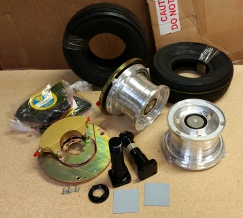
Since it wasn’t too late I still wanted to be productive, so I pulled out the Matco W50LT wheel & brake assemblies and Lamb tires to inventory all the parts and check them to ensure they were in good working order.   Some of the water soluble packing peanuts had adhered themselves to some of the wheel & brake assembly surfaces, so I spent about 15 minutes cleaning the residue off.

Main gear wheels, brakes, tubes & tires

I then spent a good 15 minutes assessing the spacing of the engine mount on the firewall to see how it aligned with the longerons (not shown).

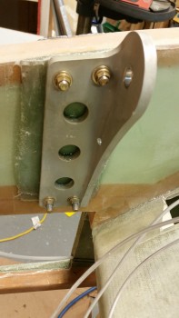
Tomorrow I plan (again) to finish up the main gear washer swap.  Also, as the flox & BID cures on the upper gear bolt holes tomorrow, I’ll be working on a piece of 4130 metal extrusion to create the inboard wheel pant mounting brackets.  These brackets will be mounted on the backside of the axles when they’re mounted.