Chapter 13 – Happy Thanksgiving!

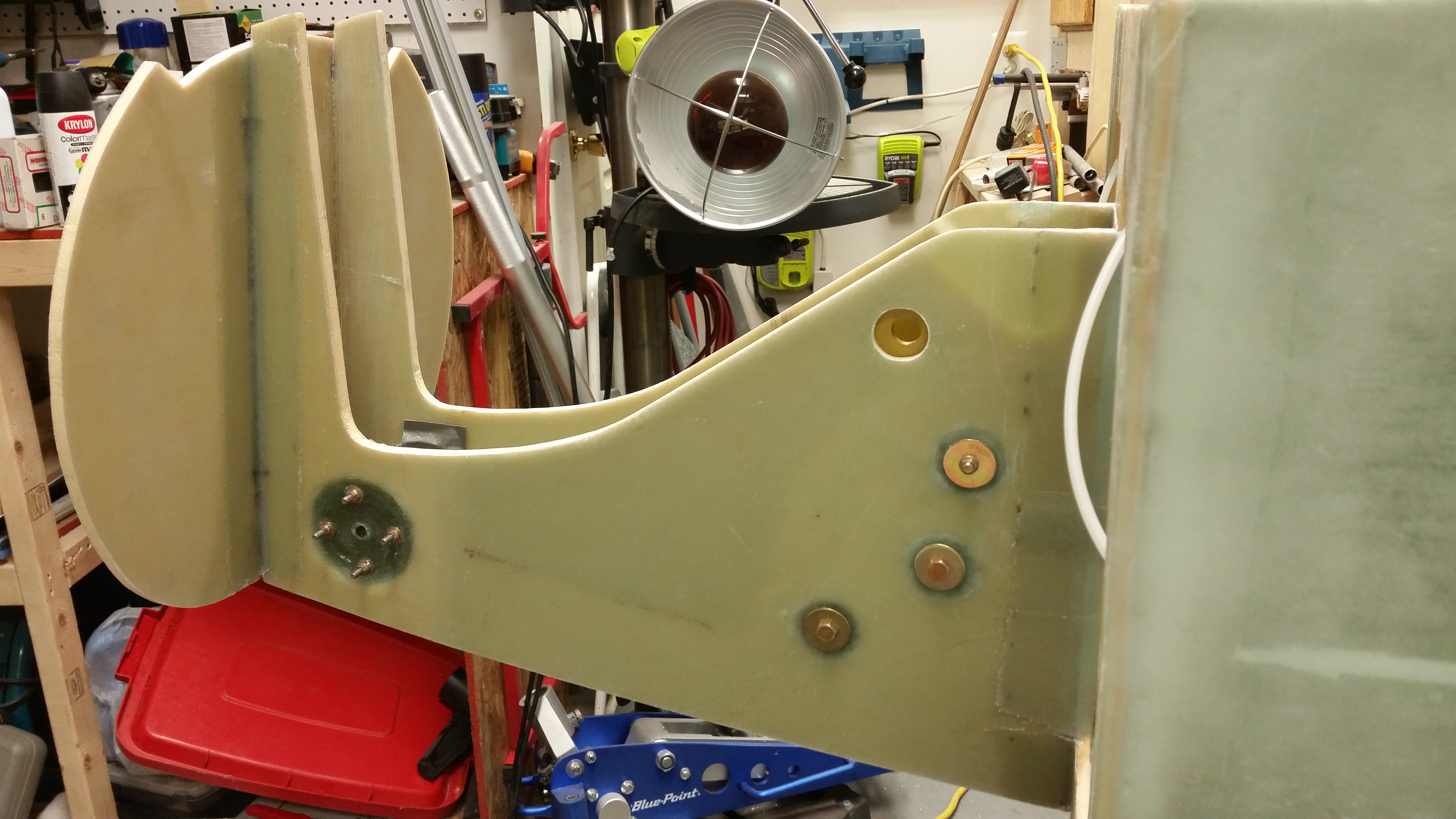
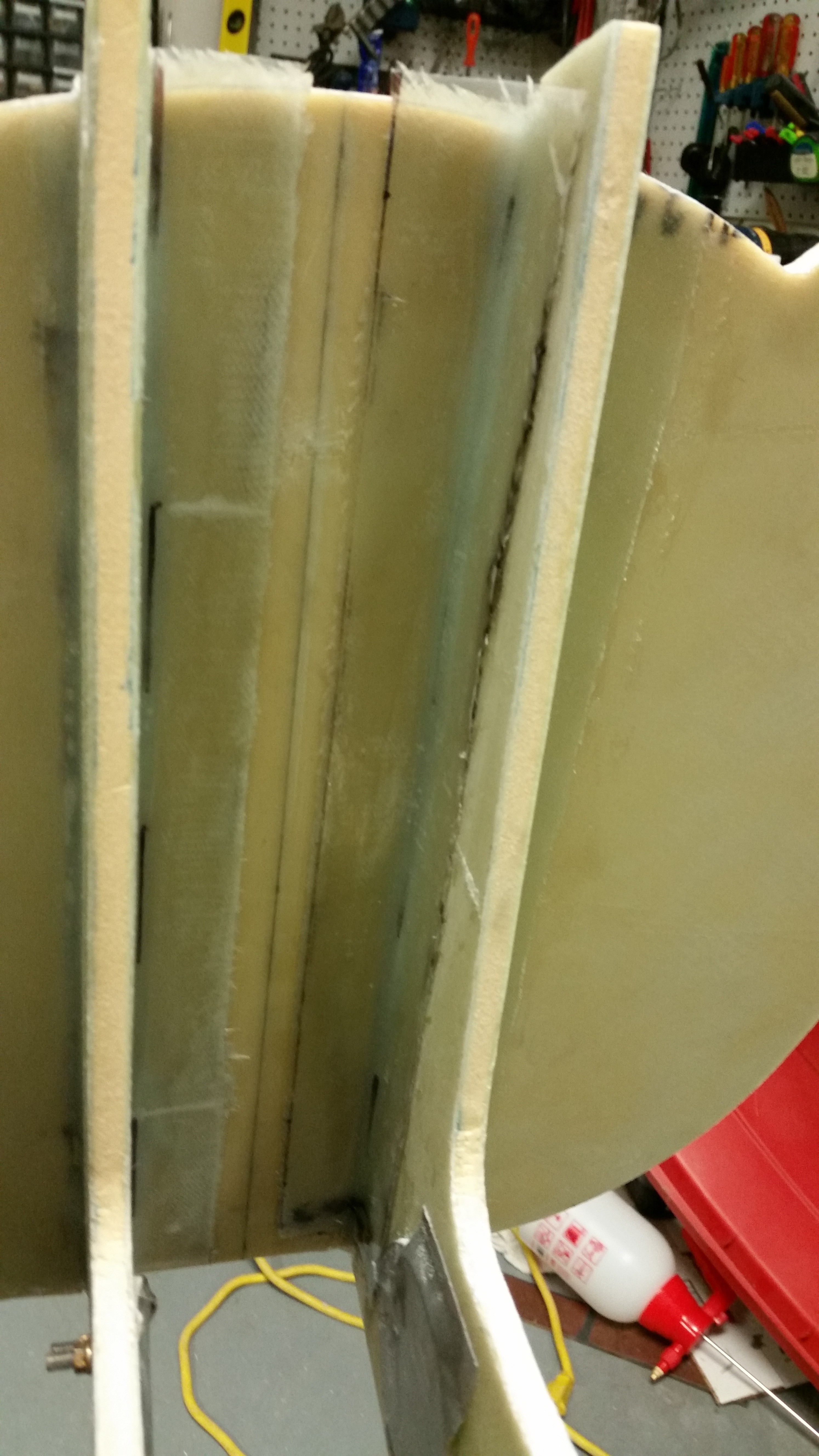
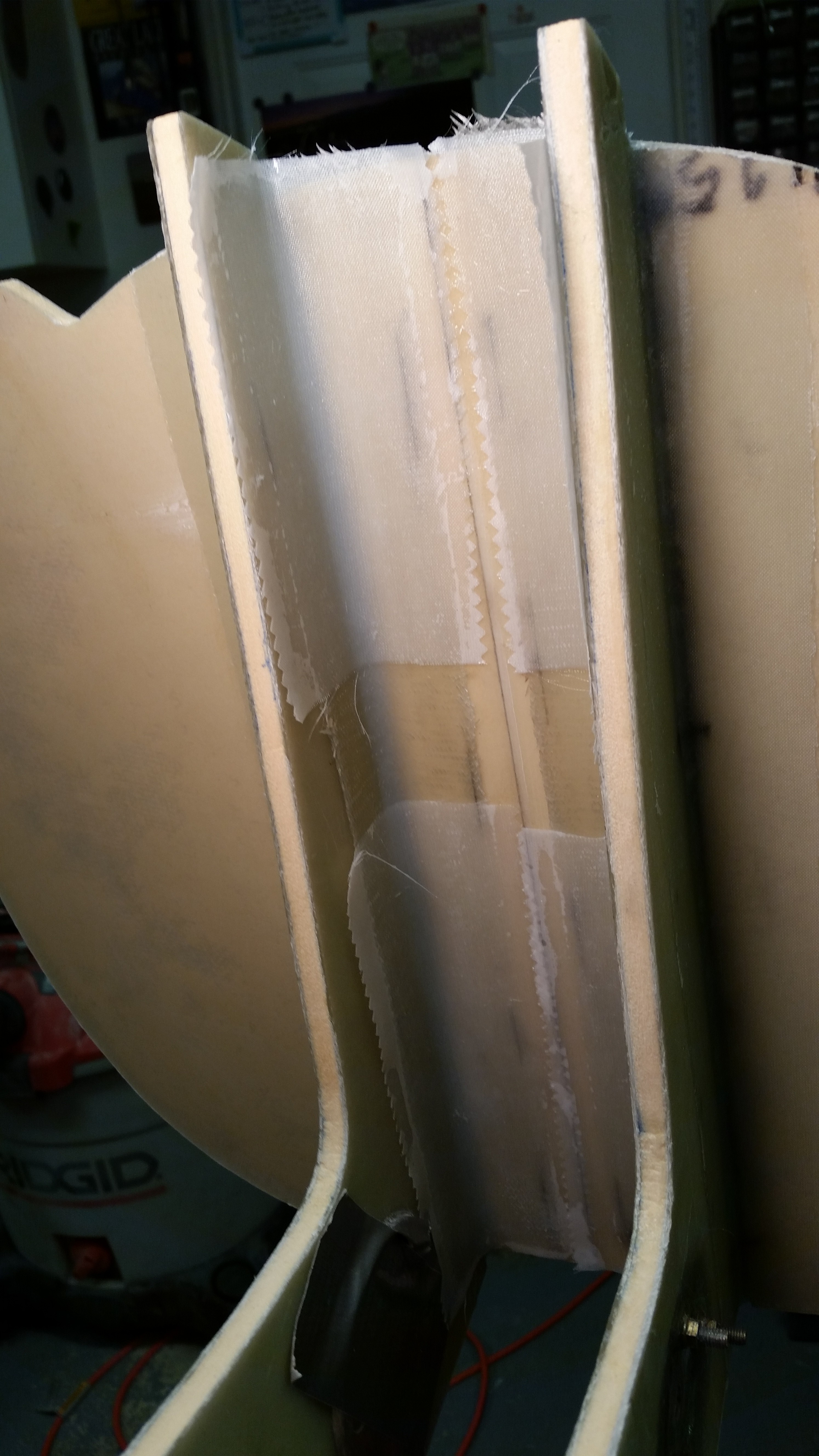
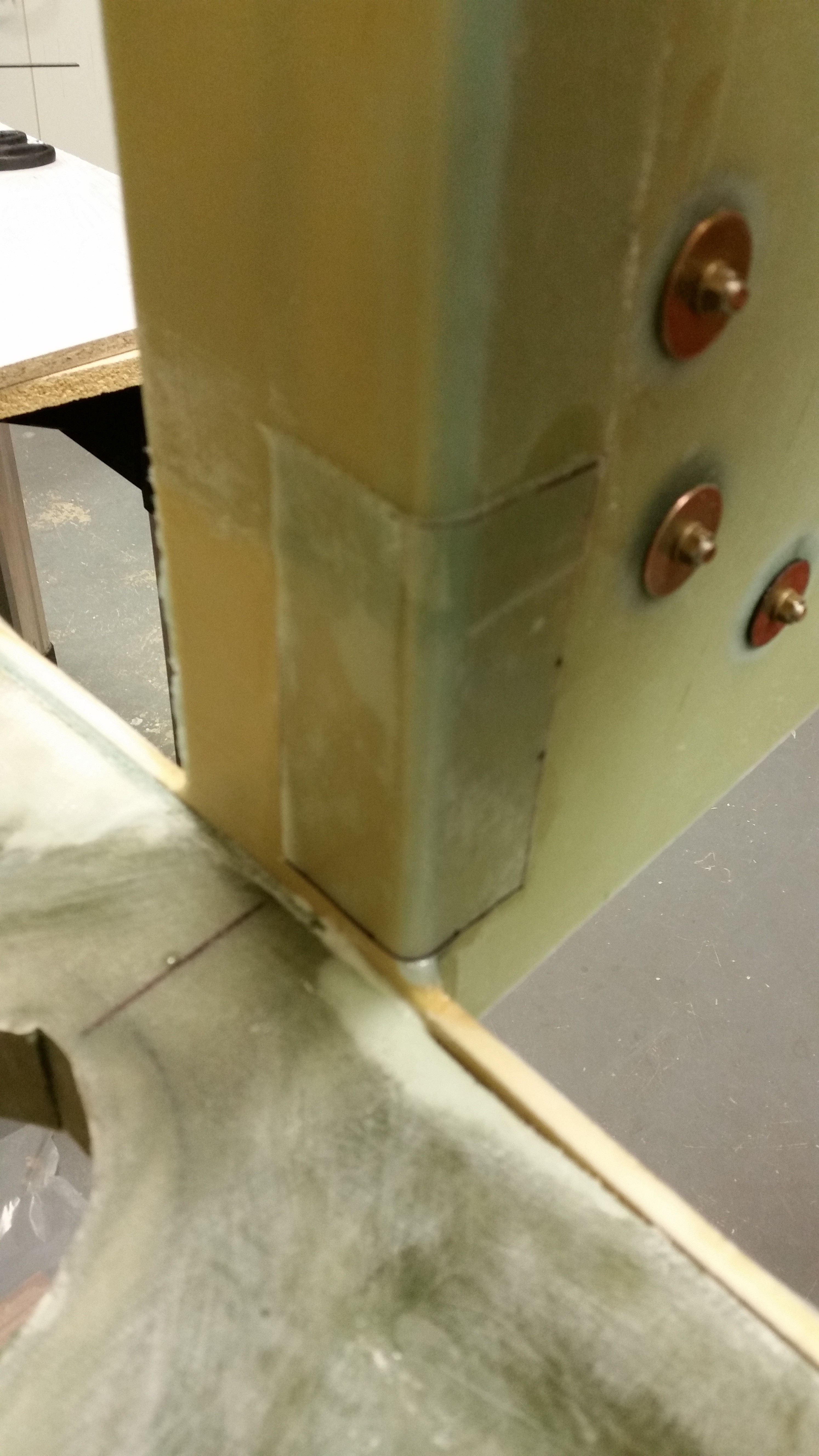
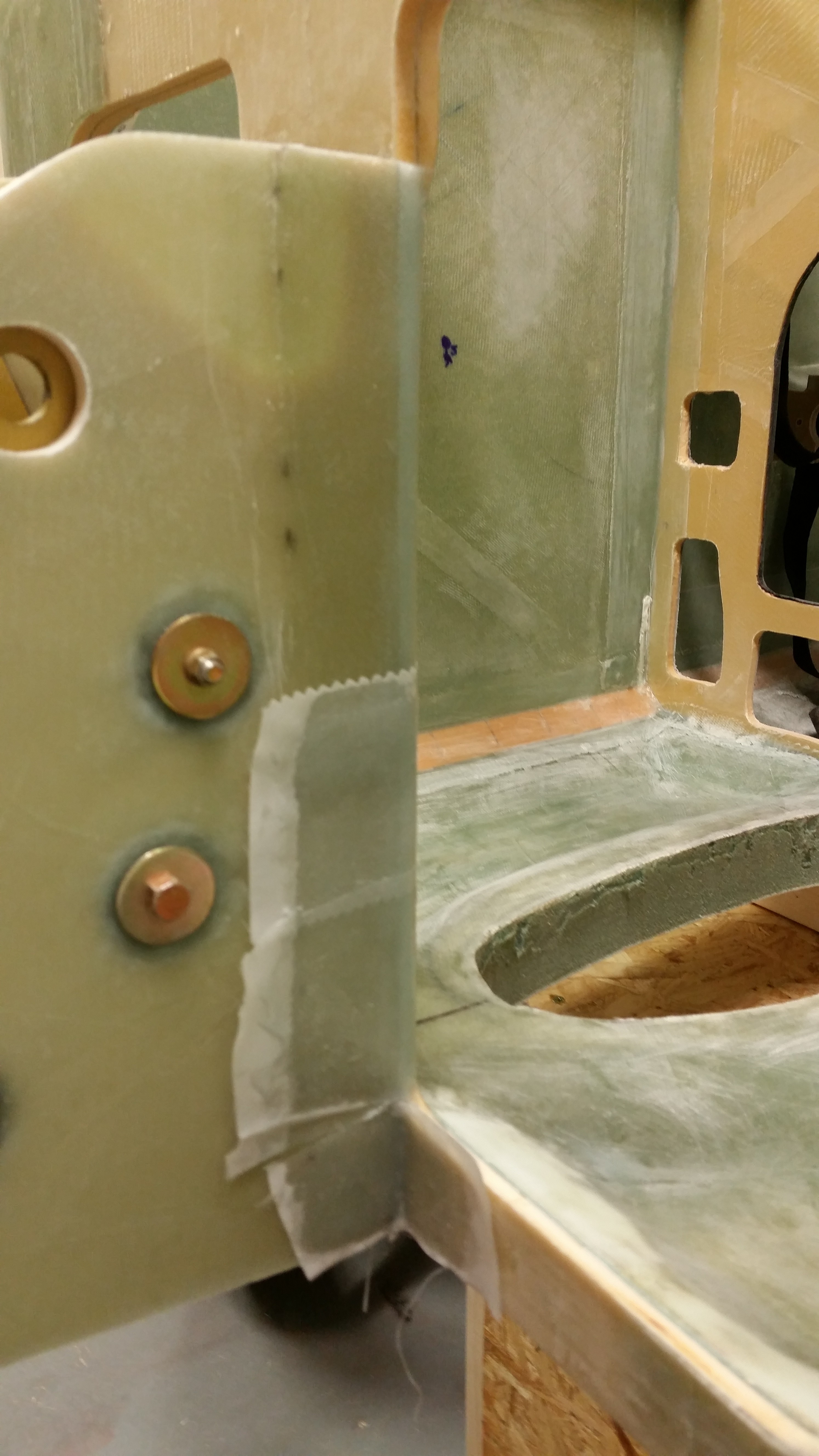
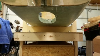
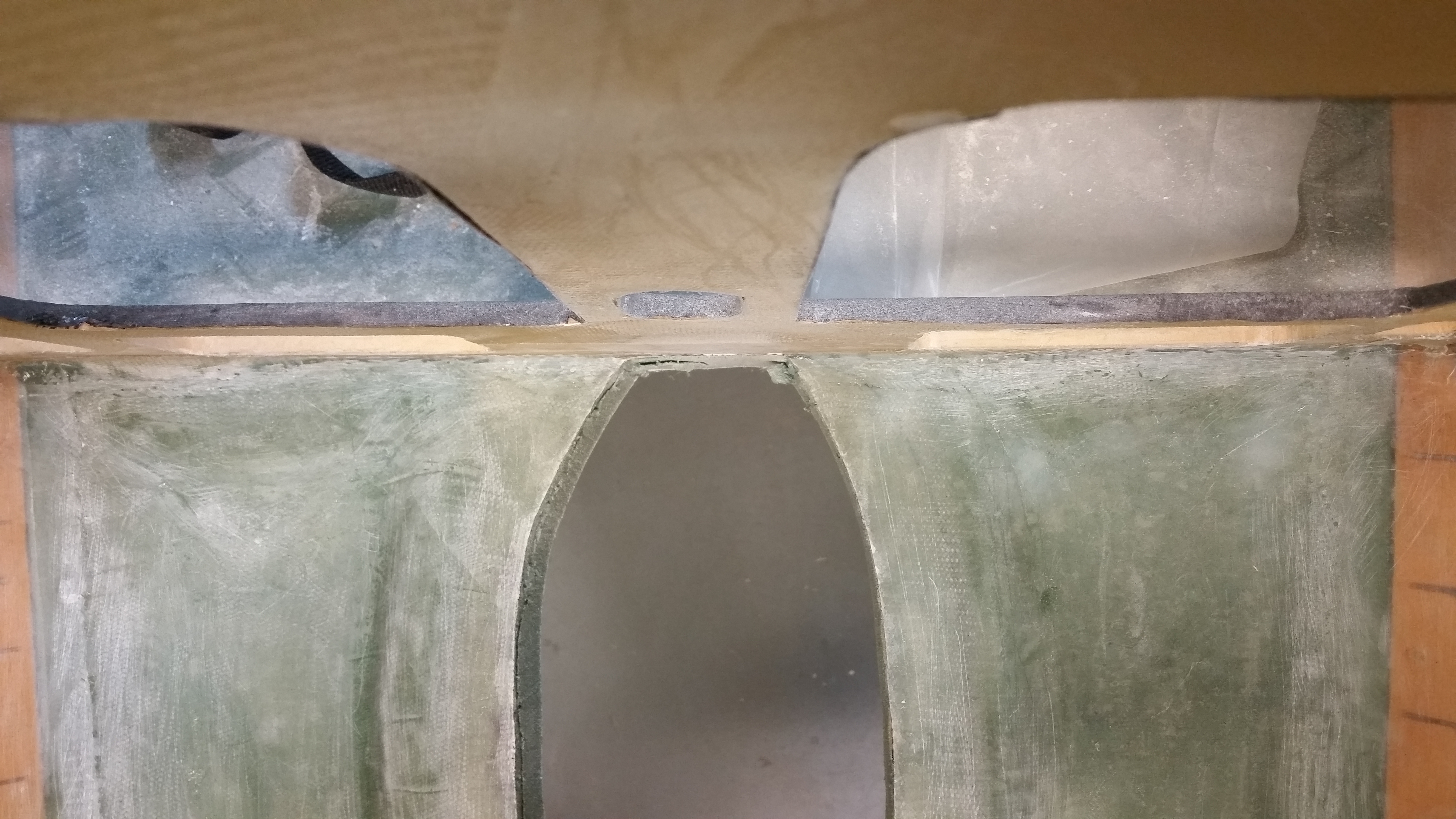
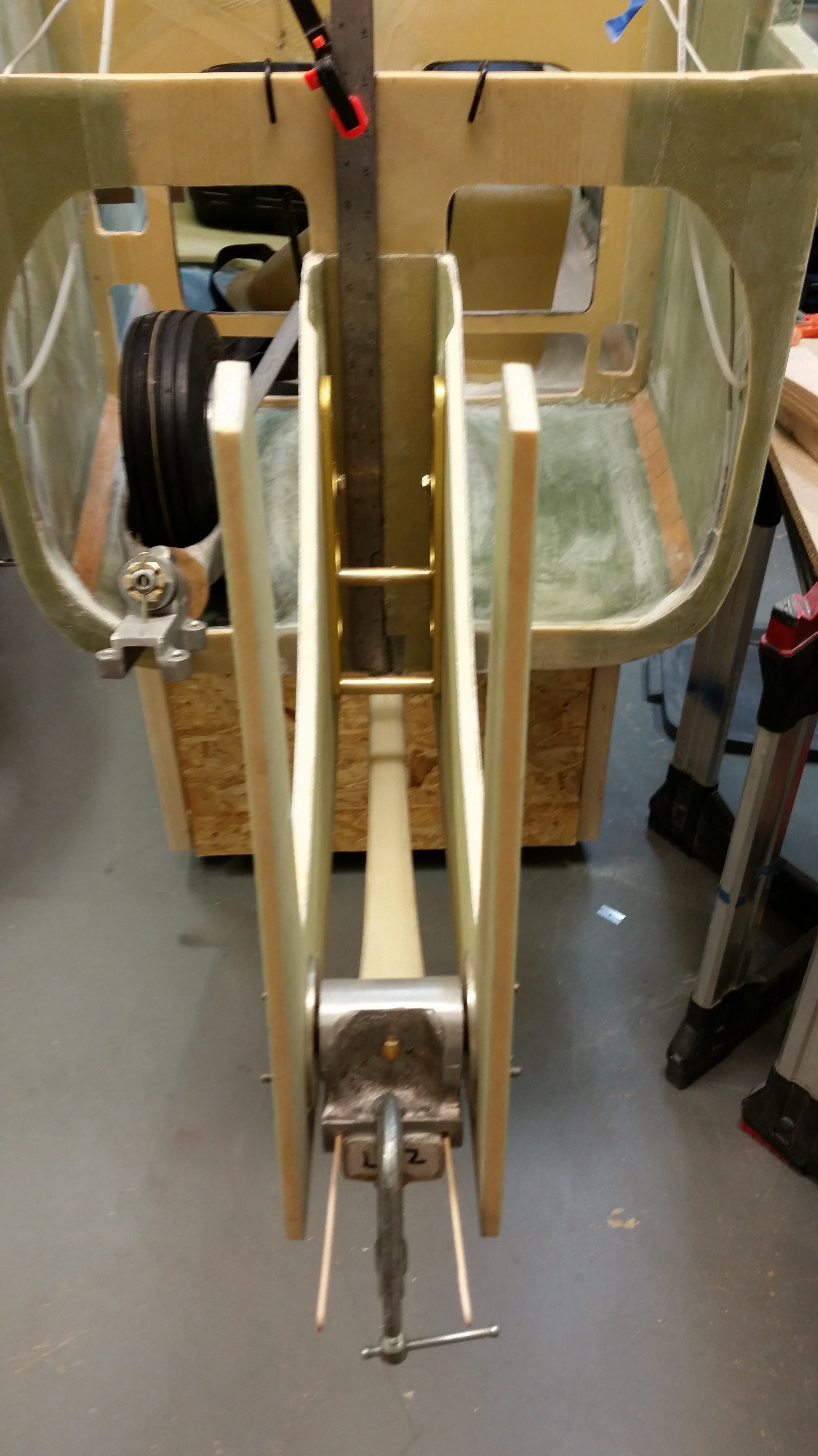
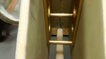
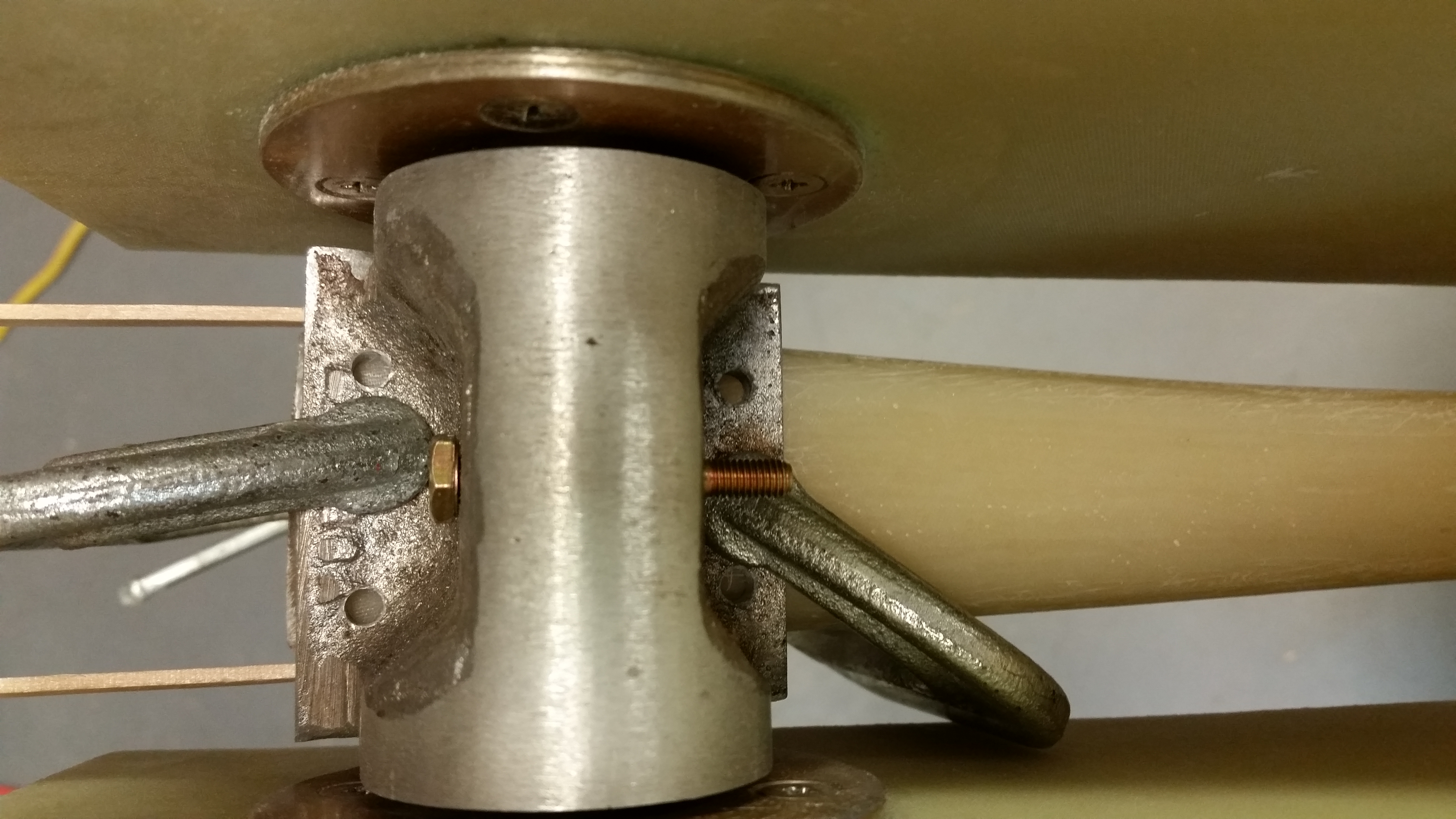
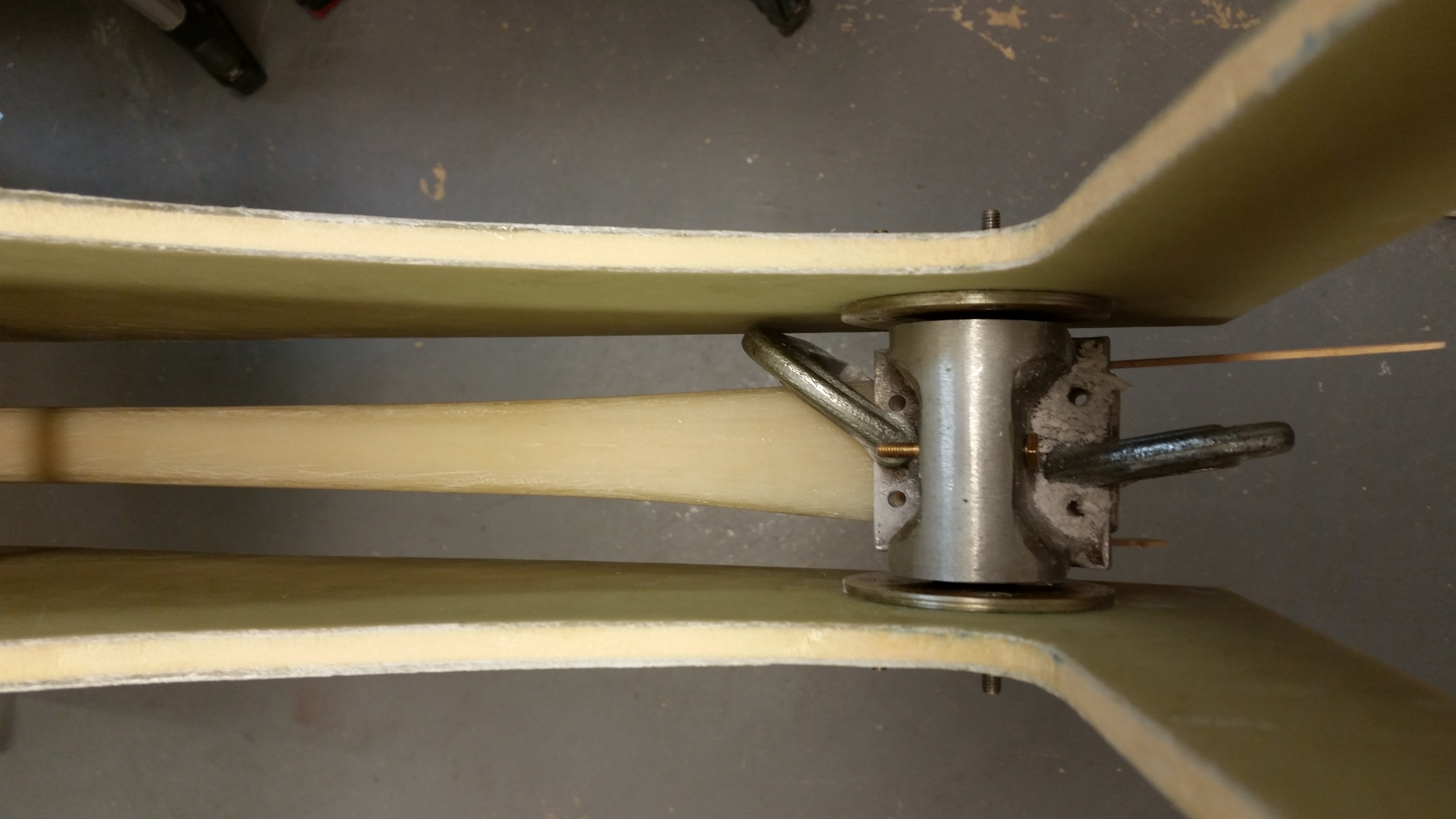
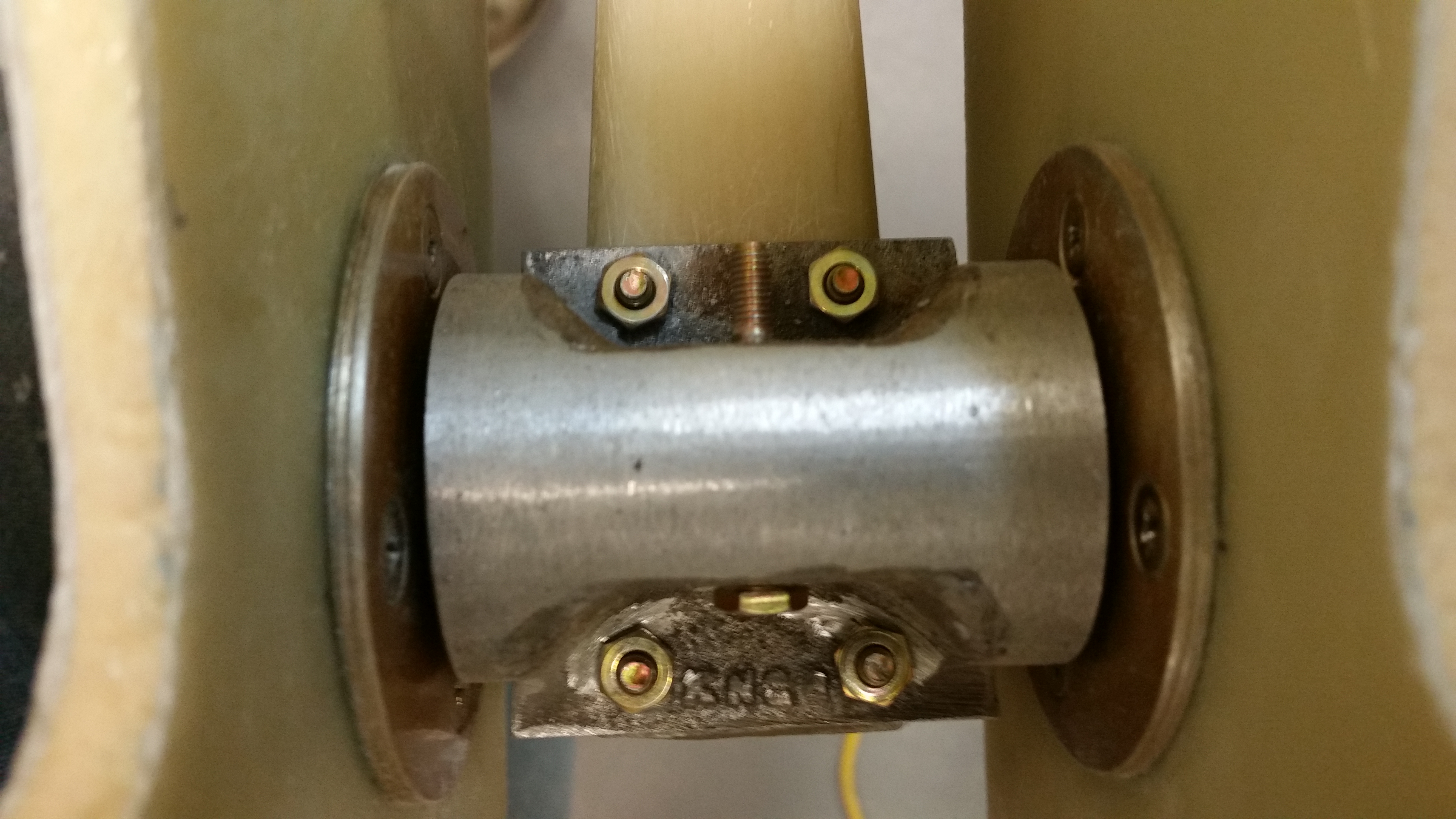
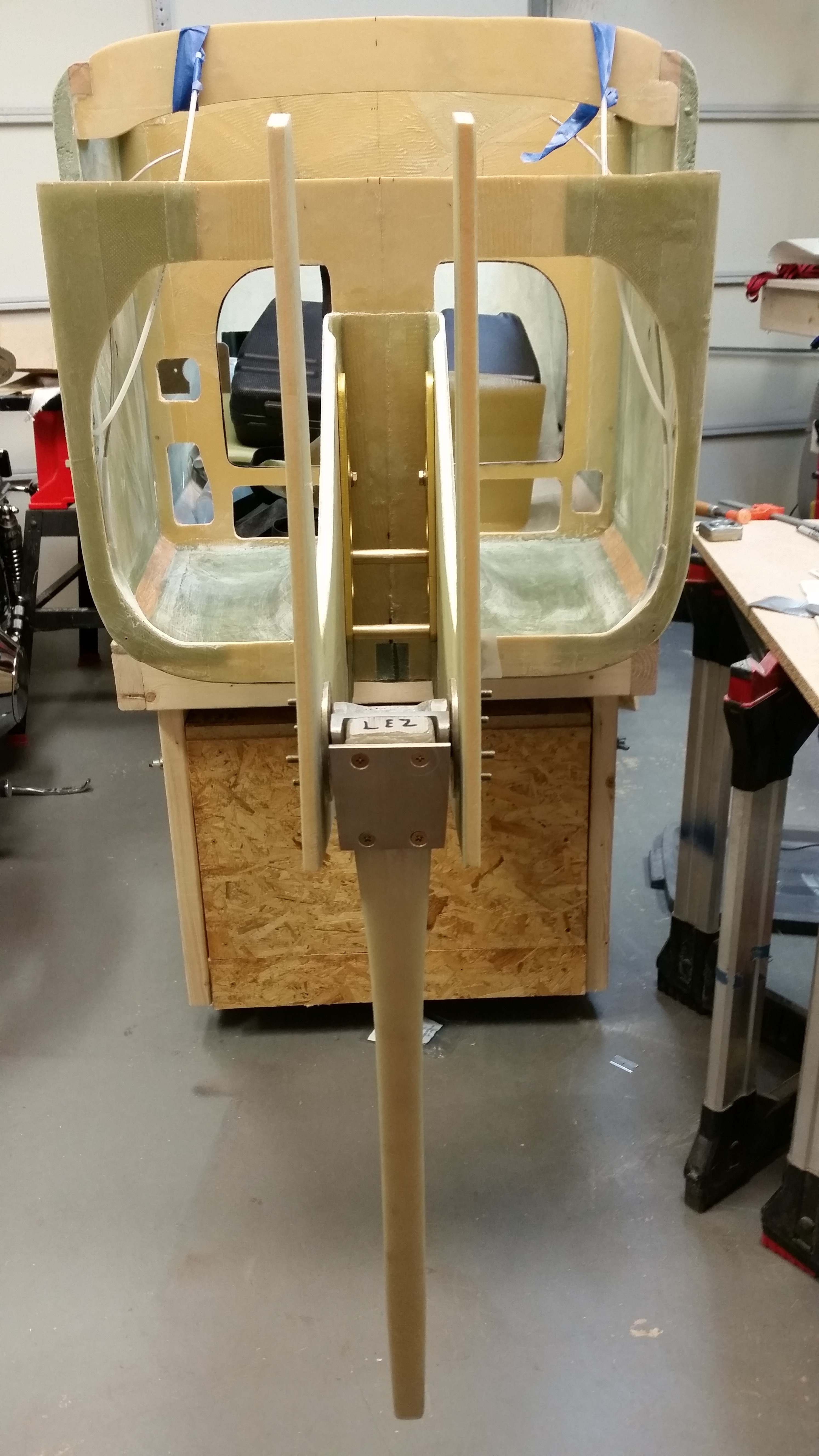
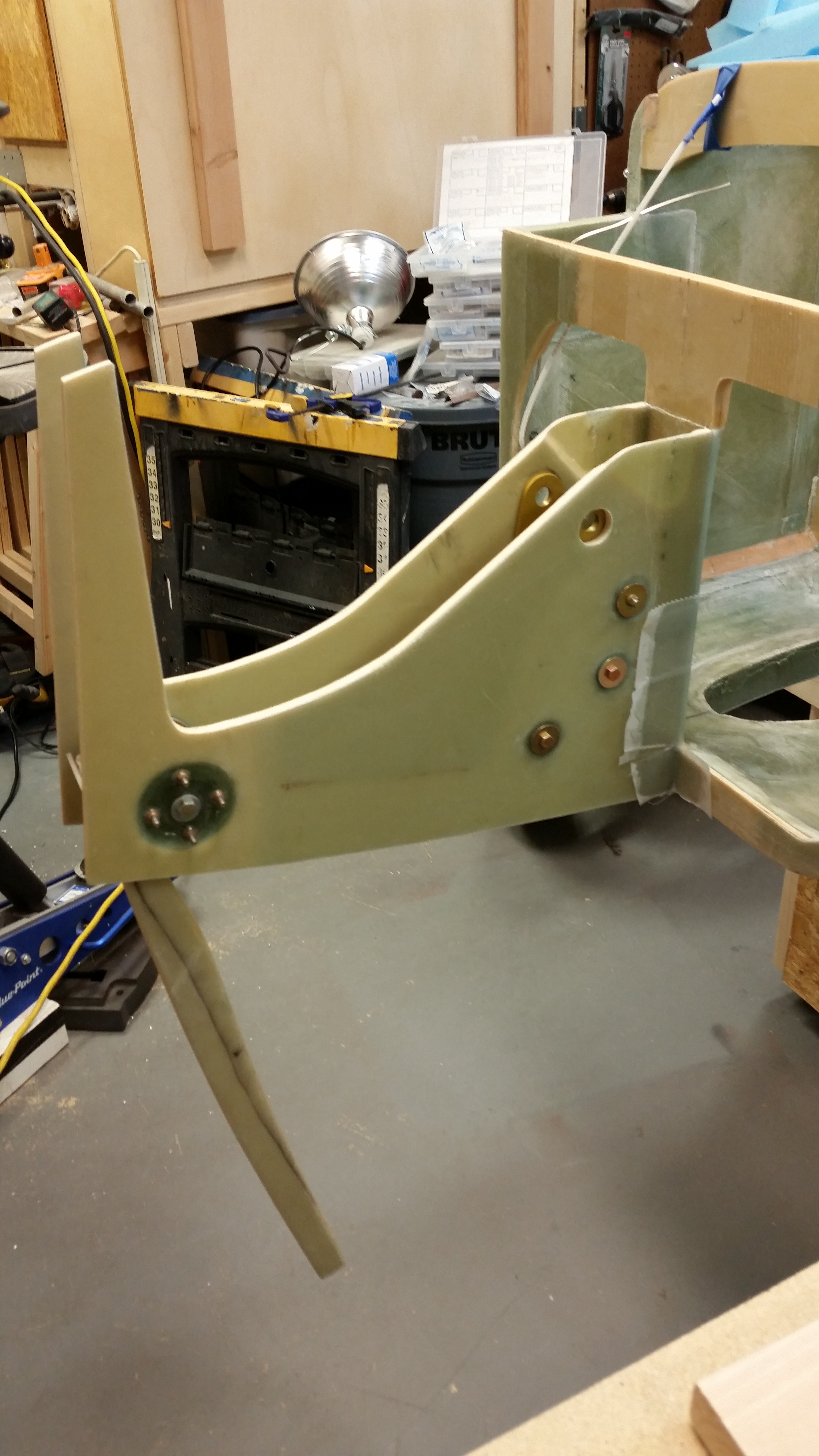
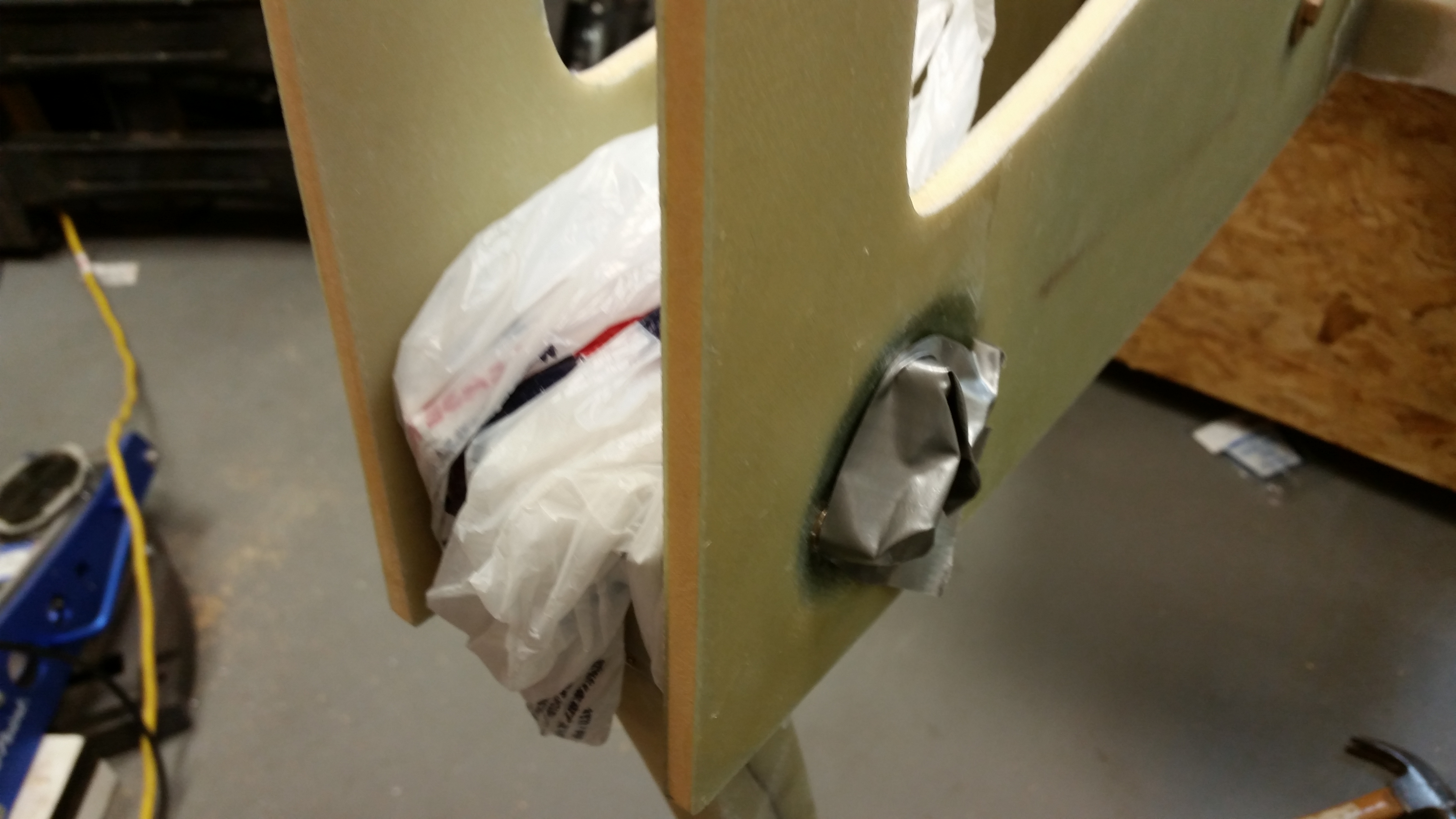
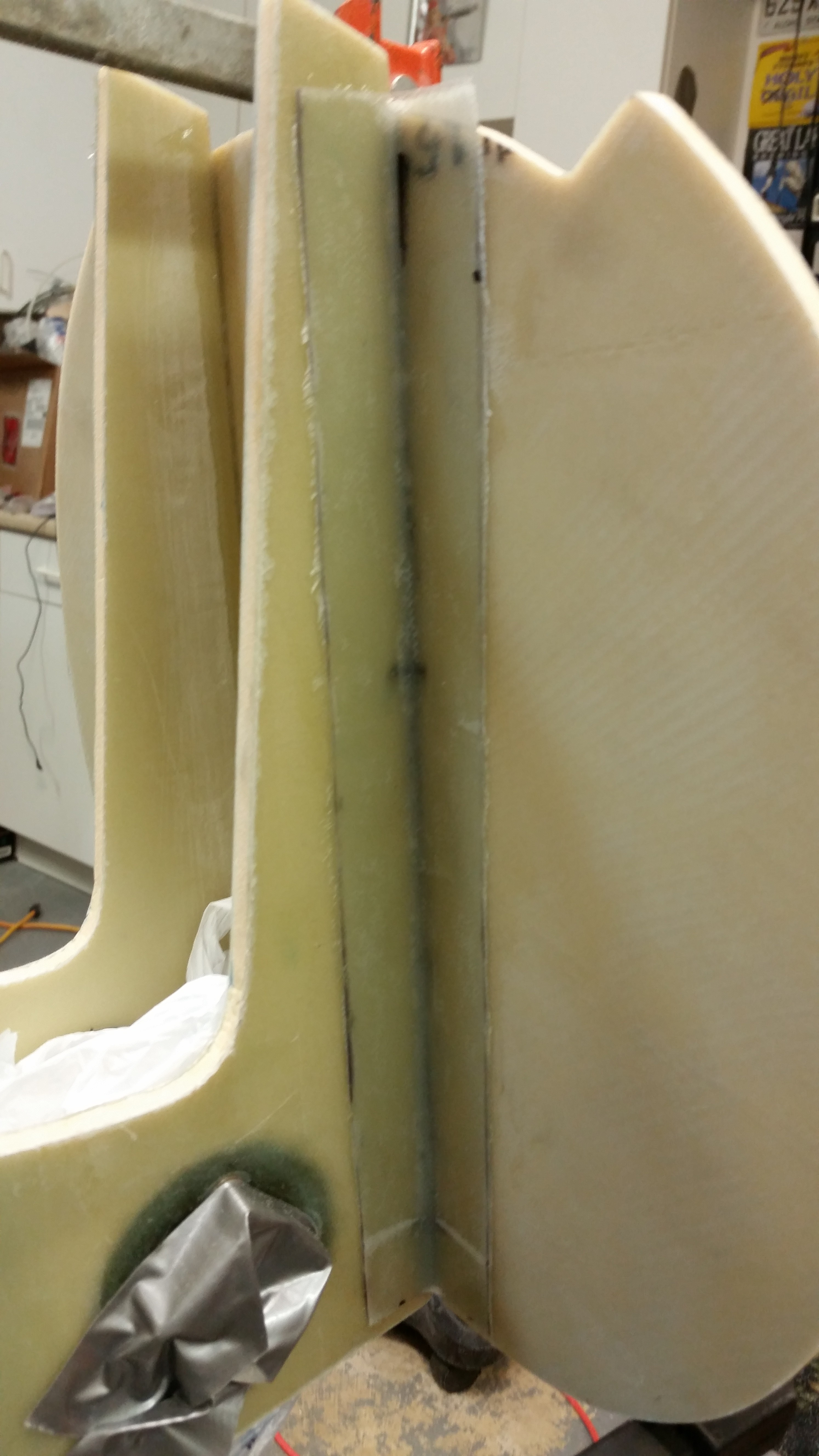
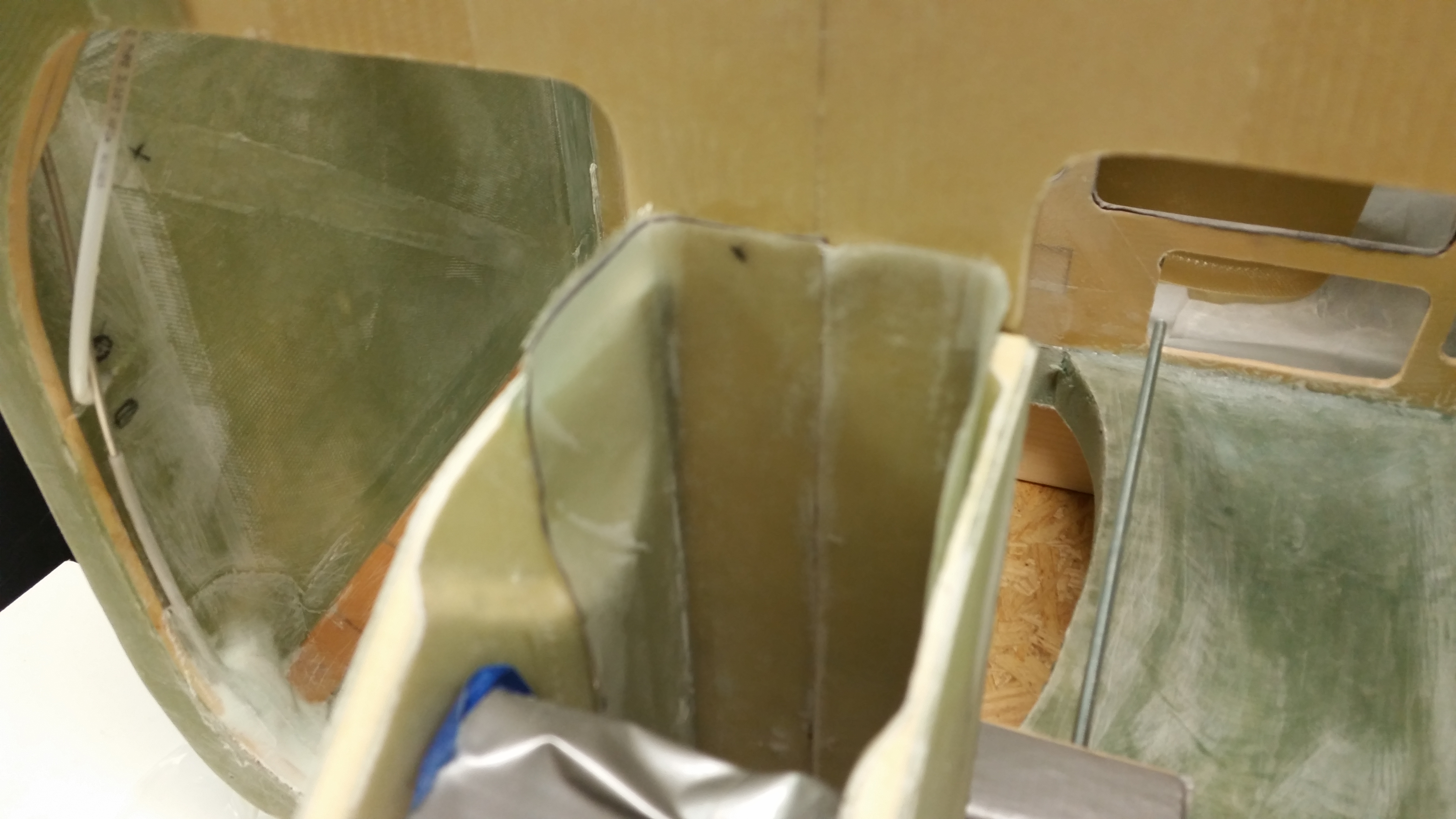
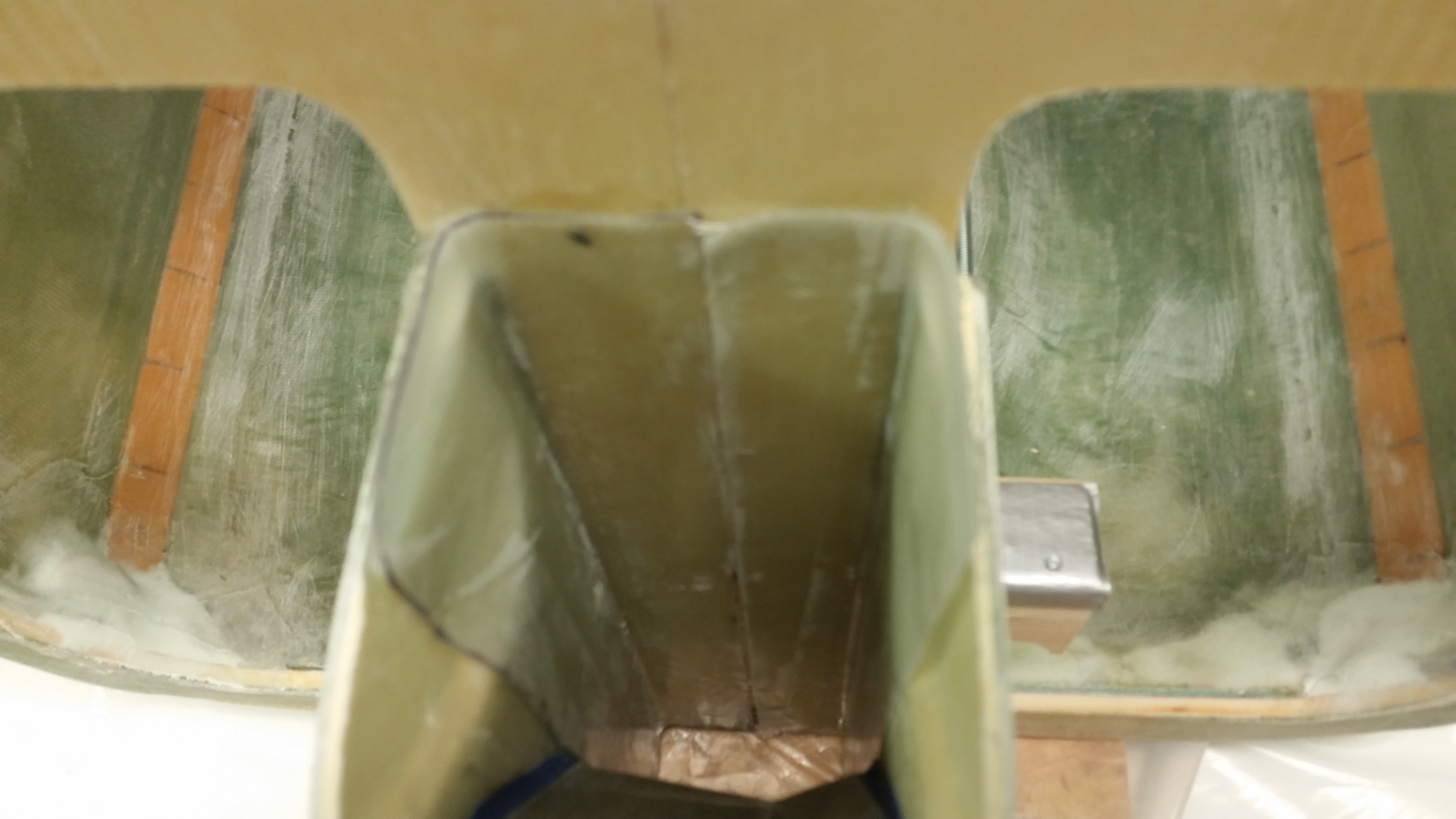
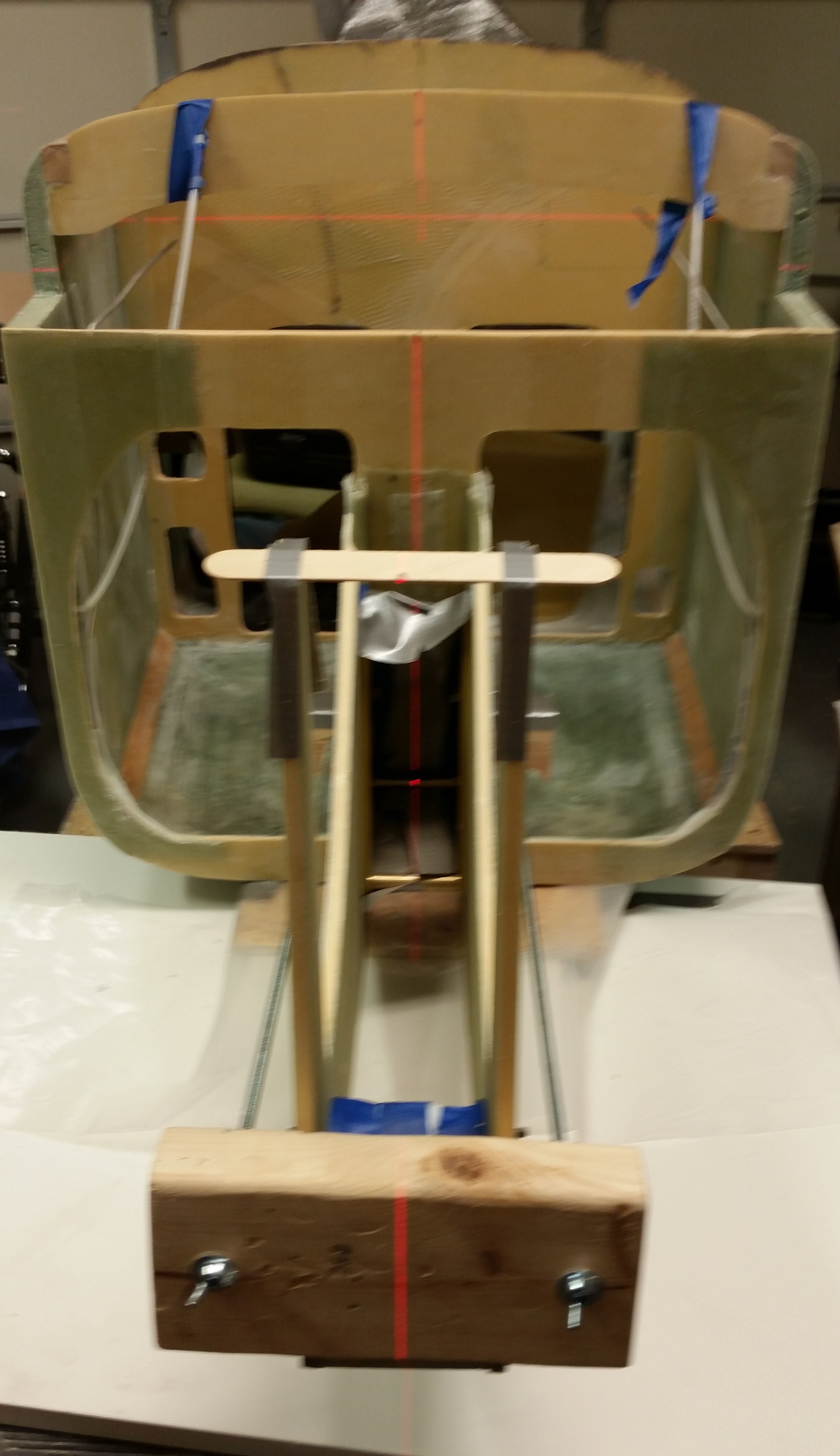
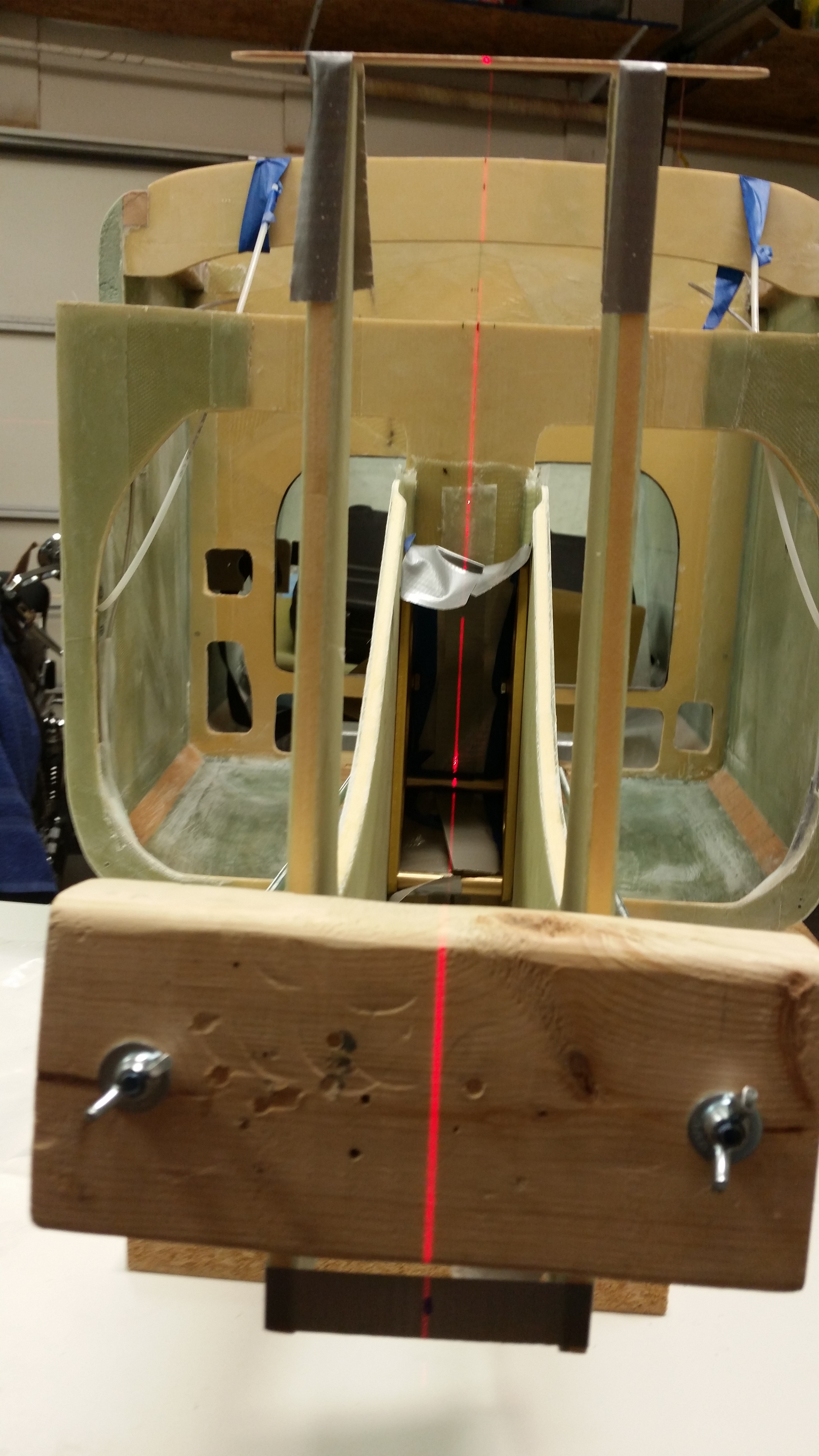
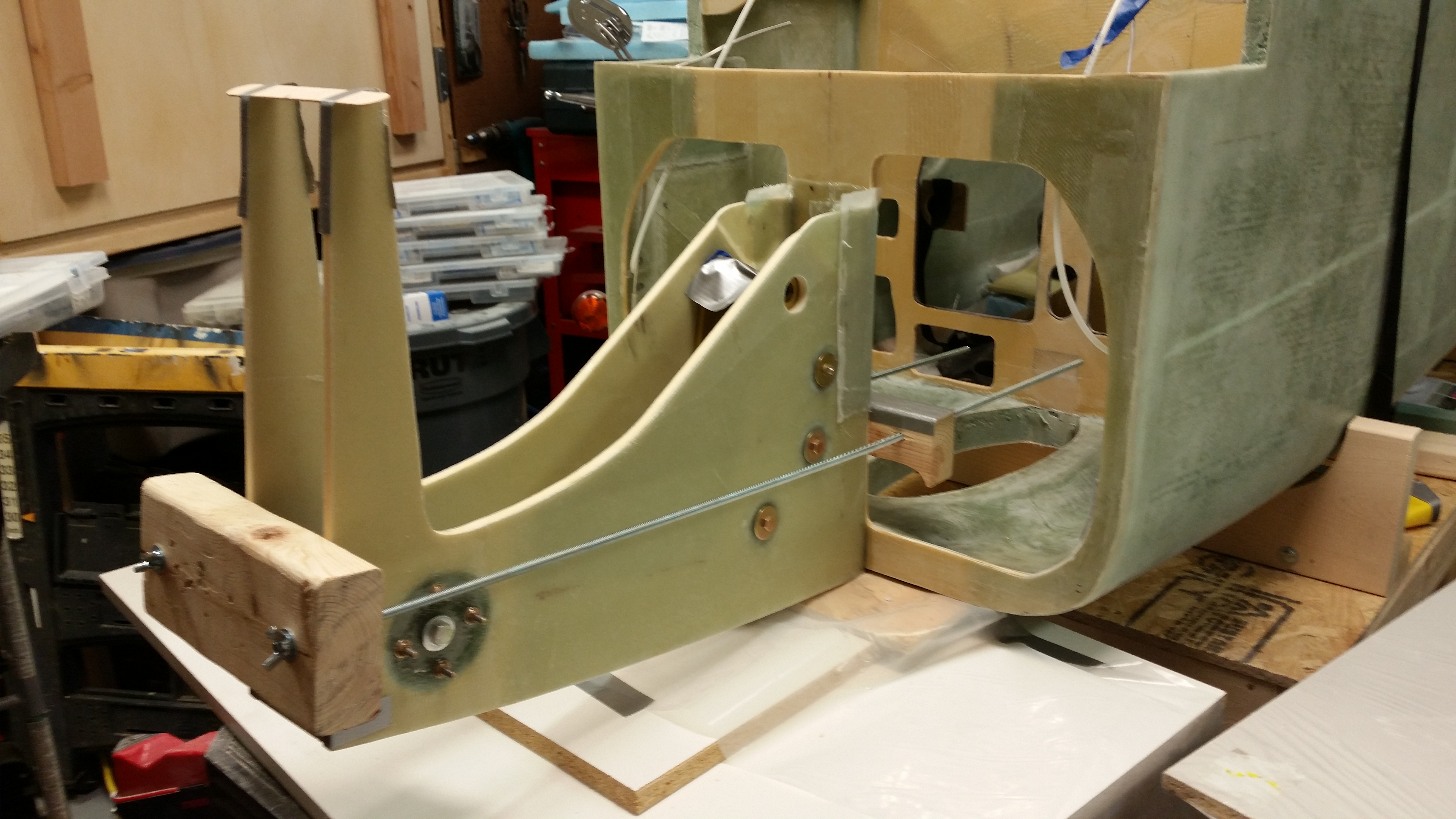
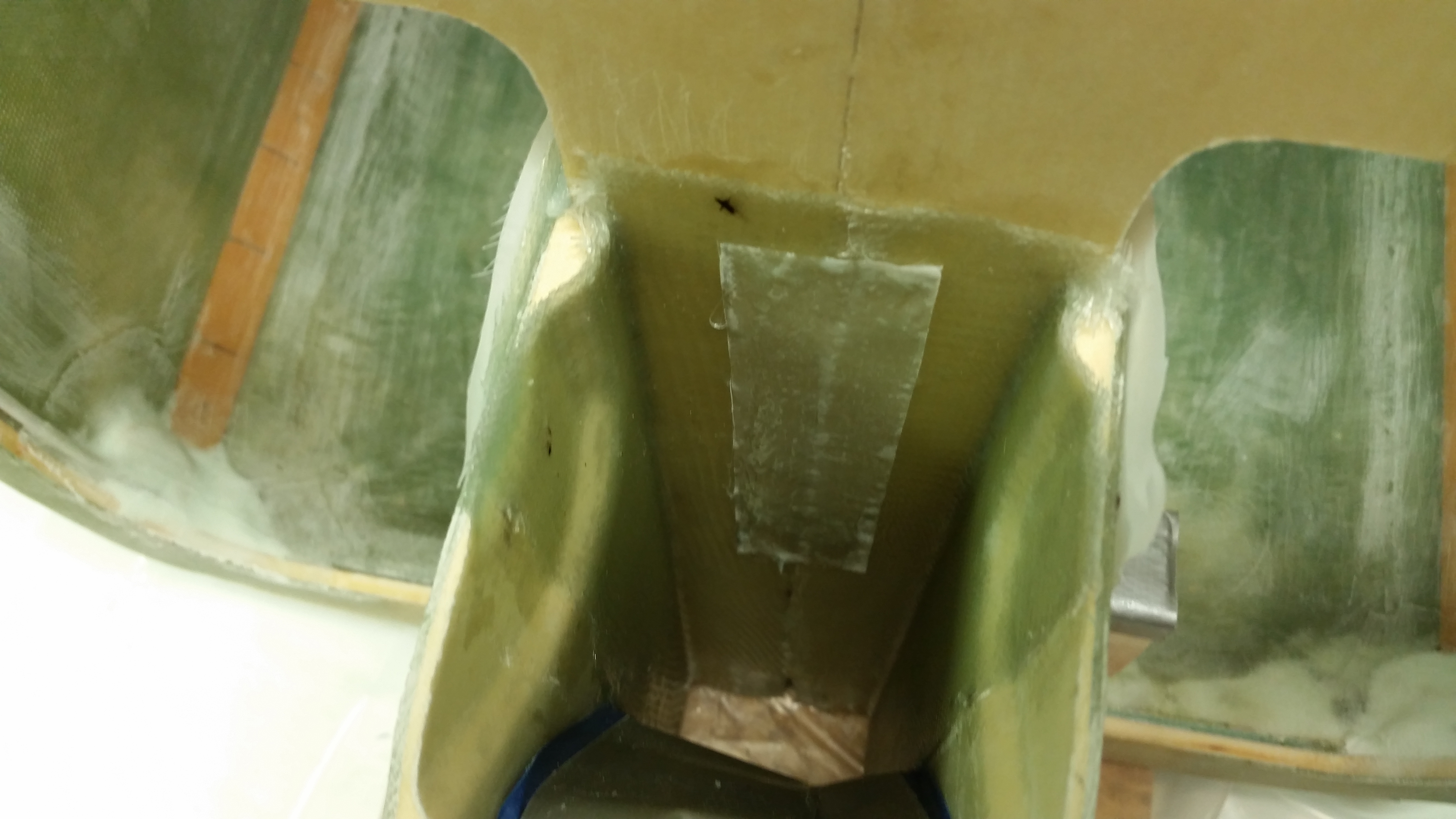
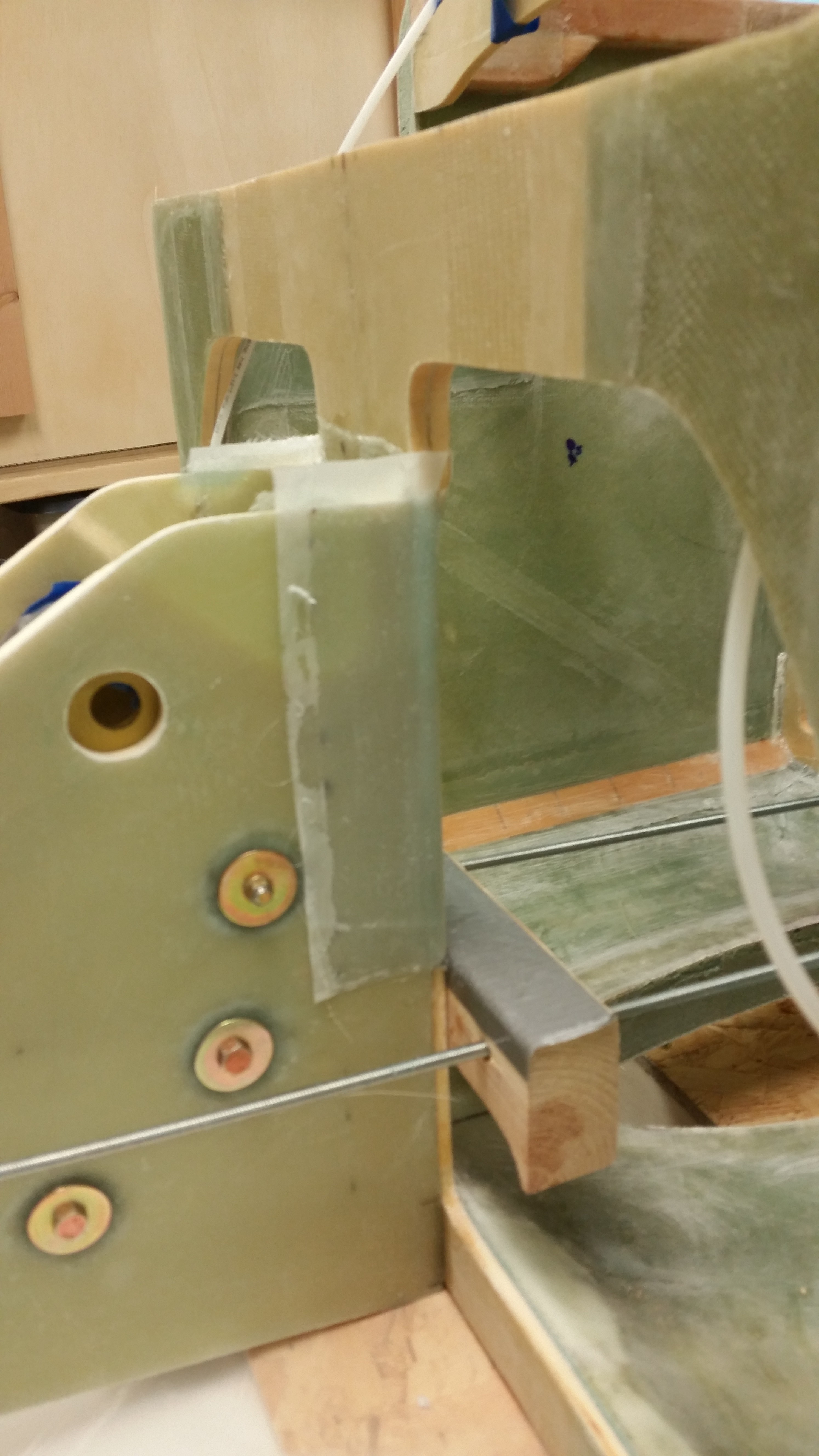
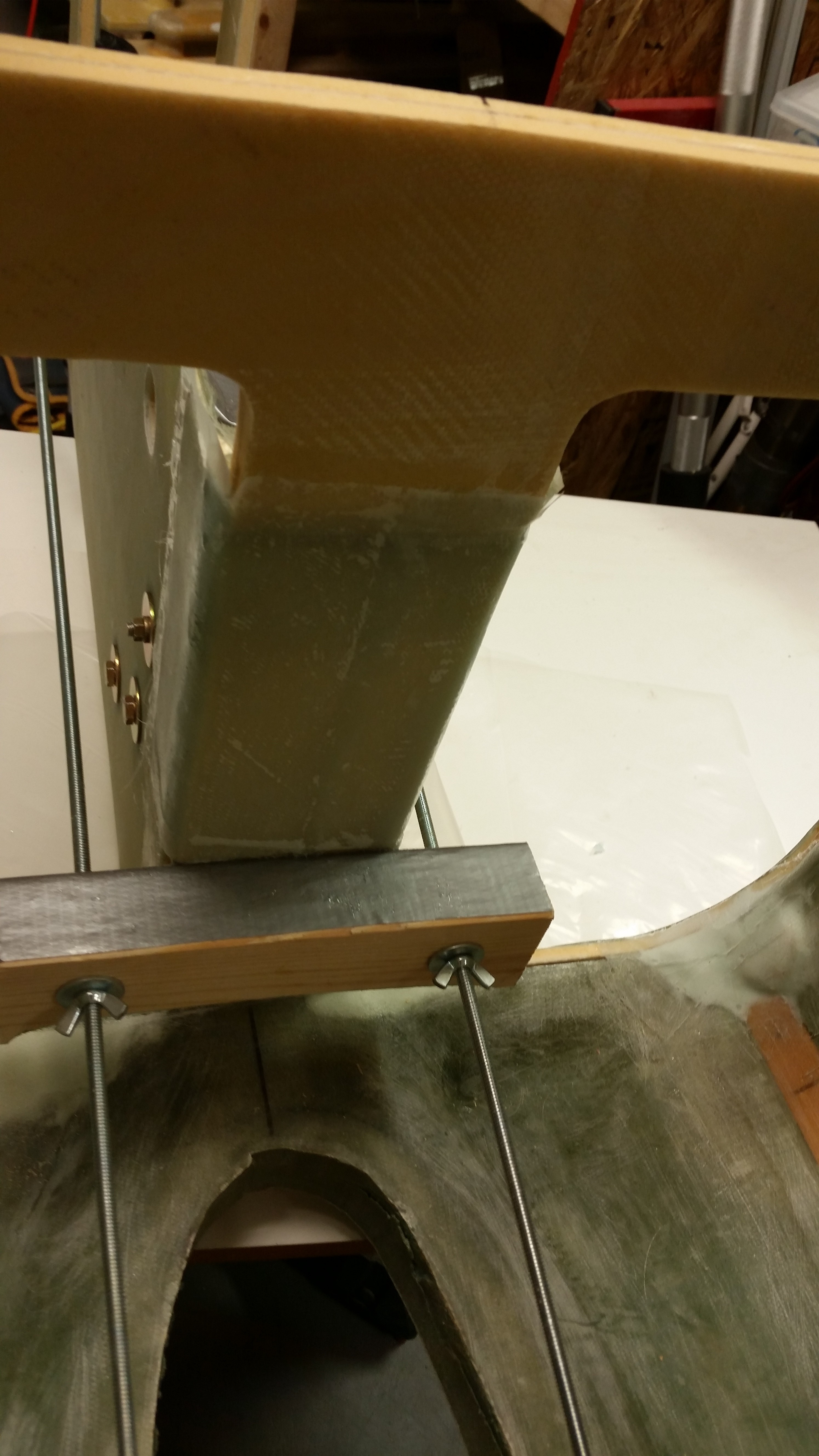
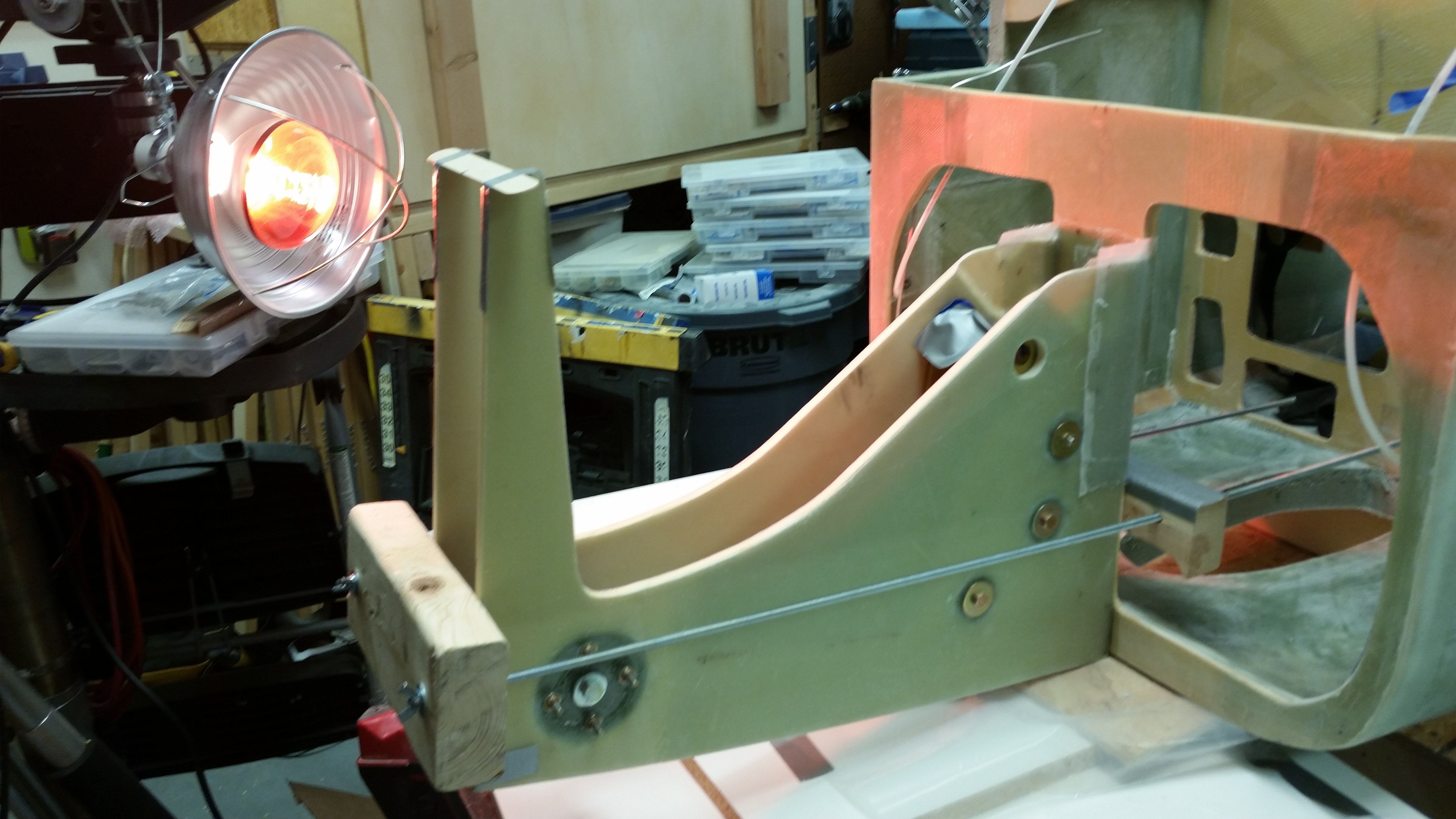
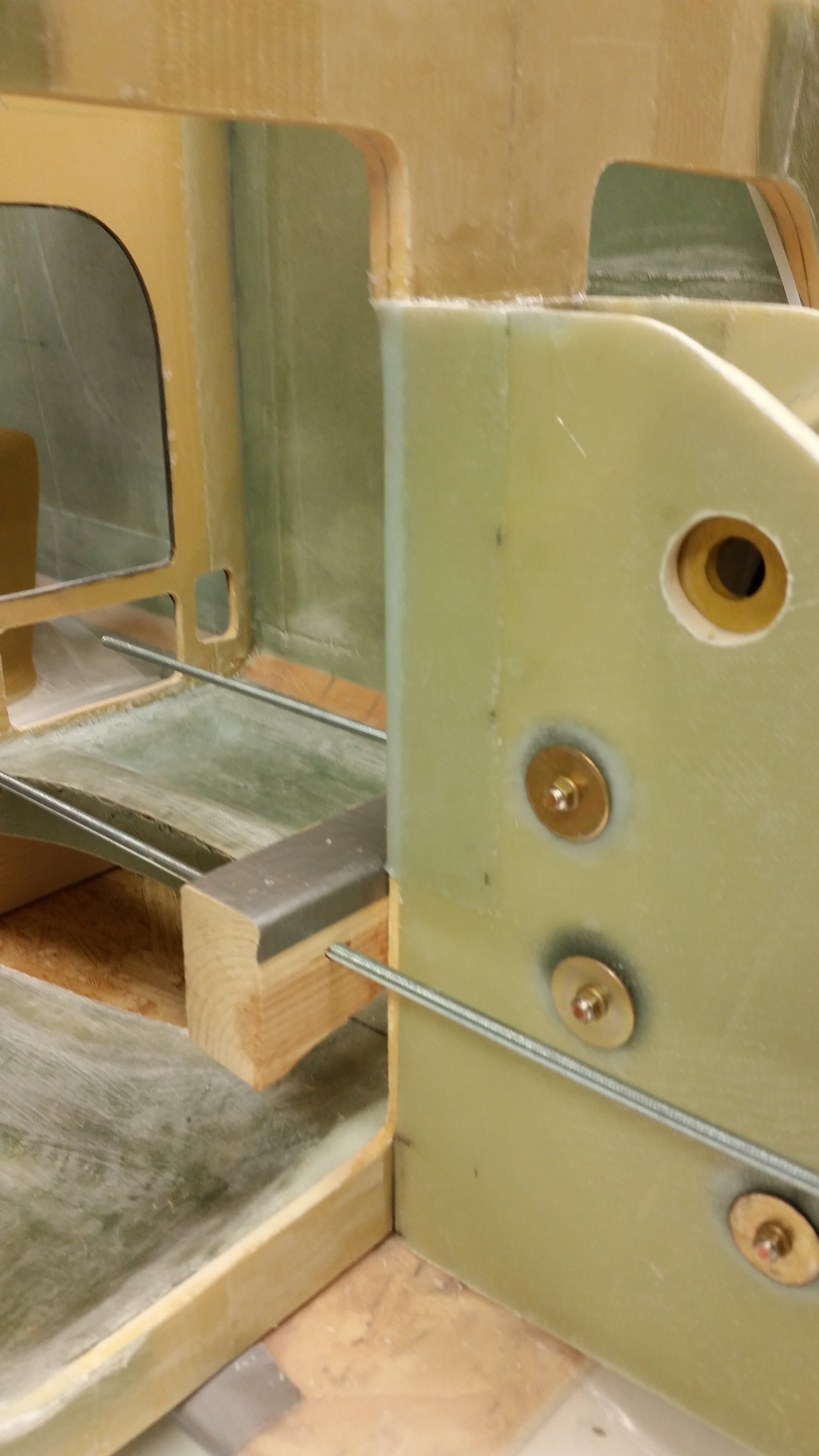
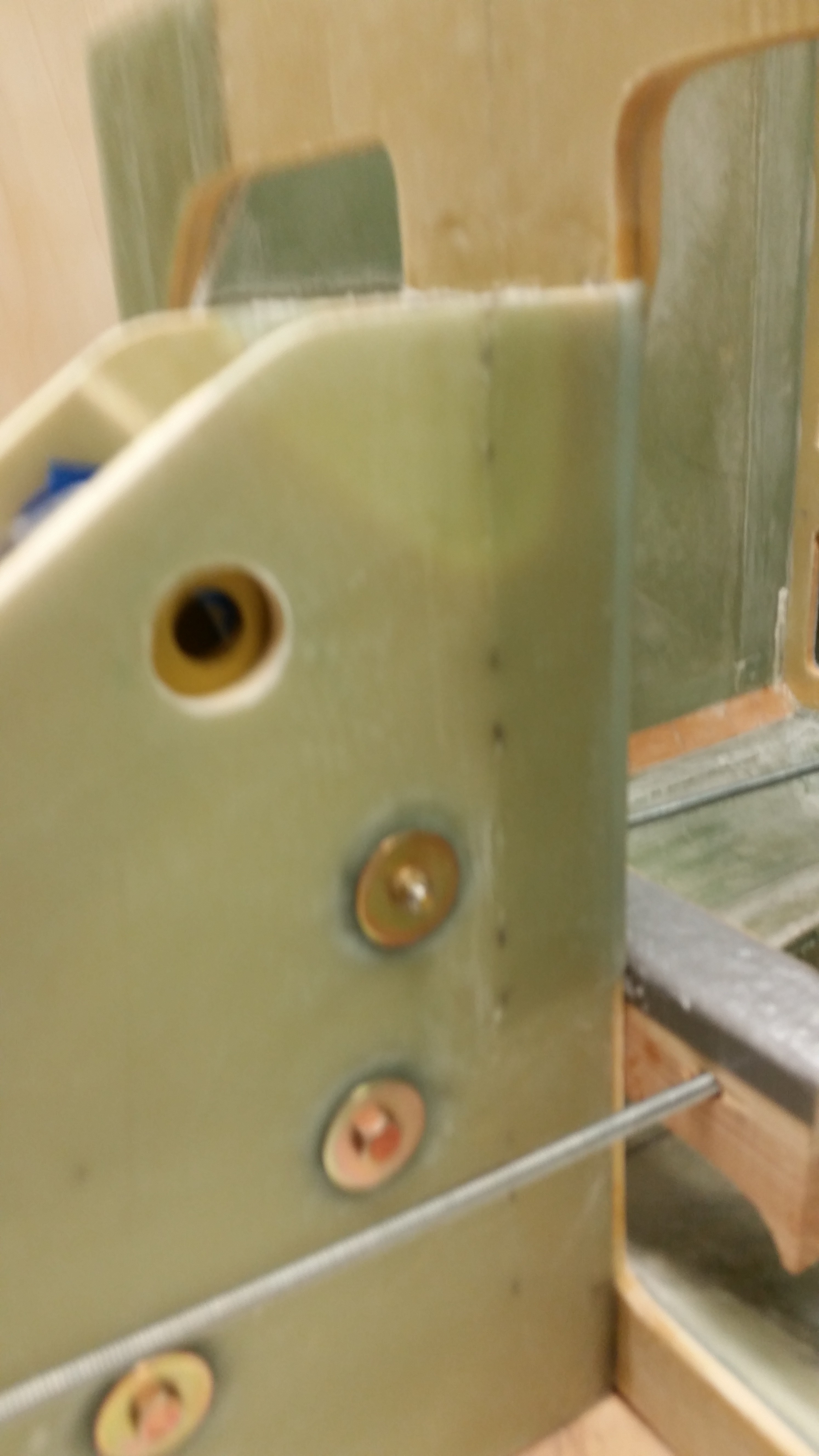
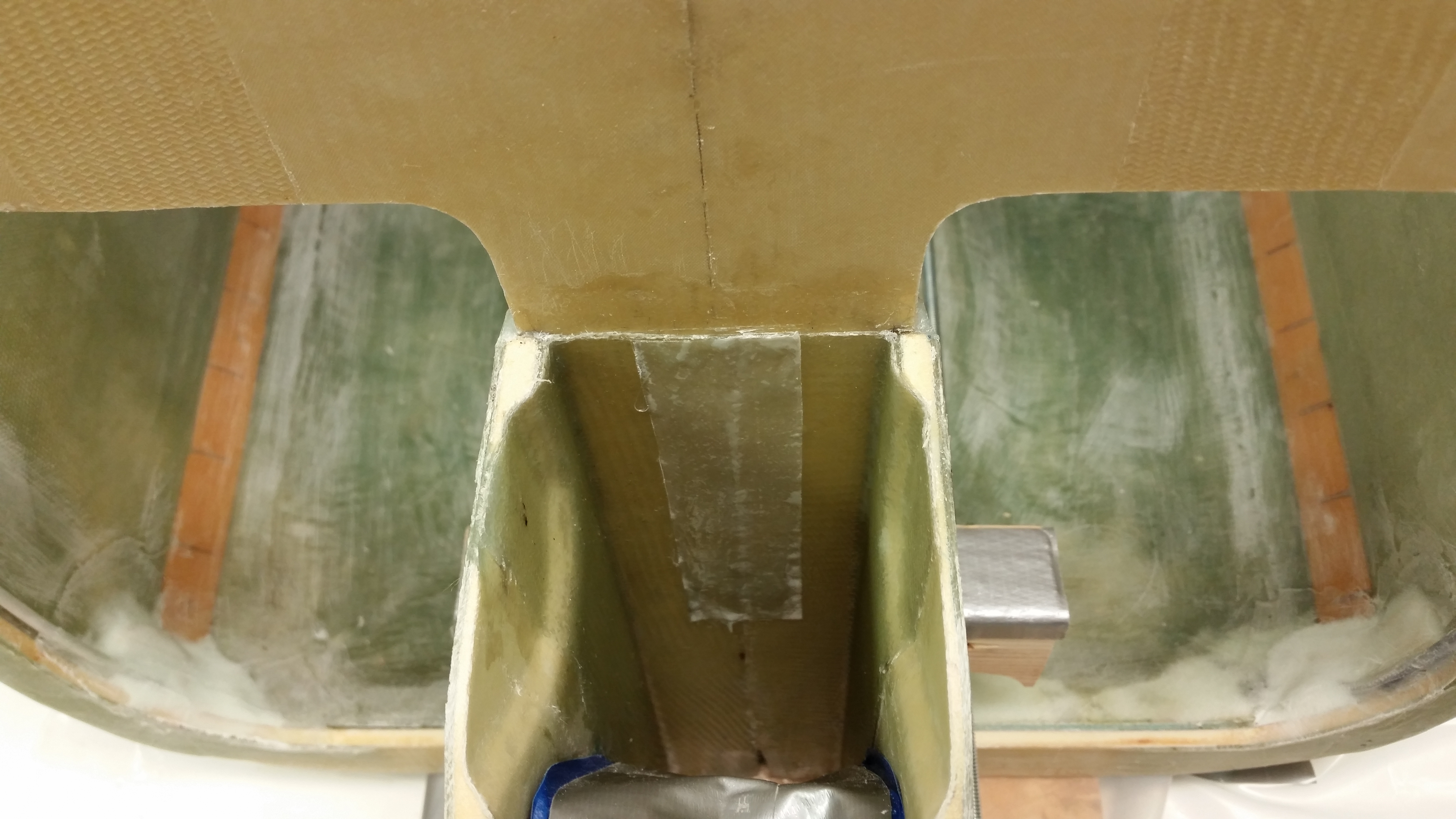
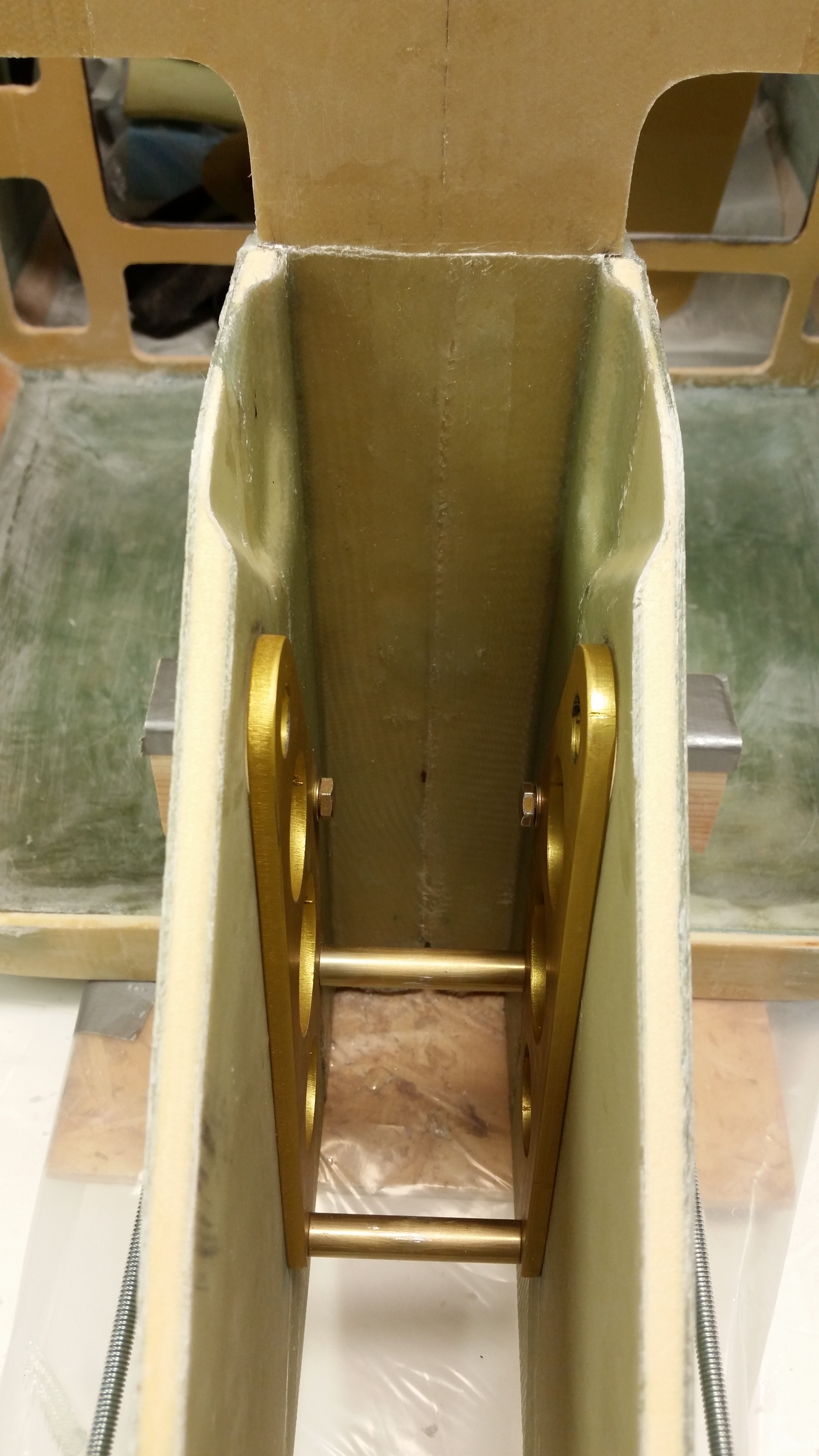
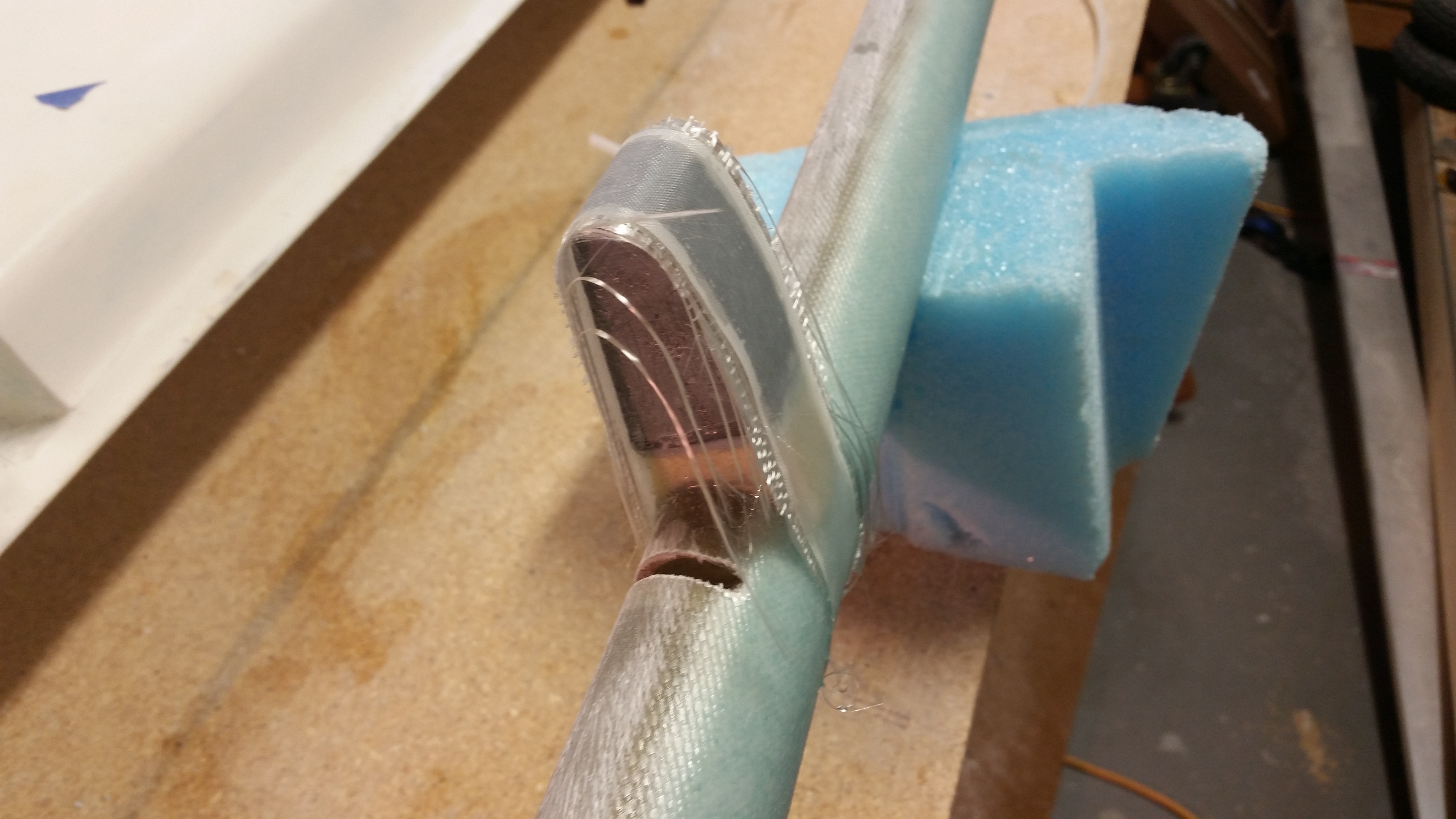
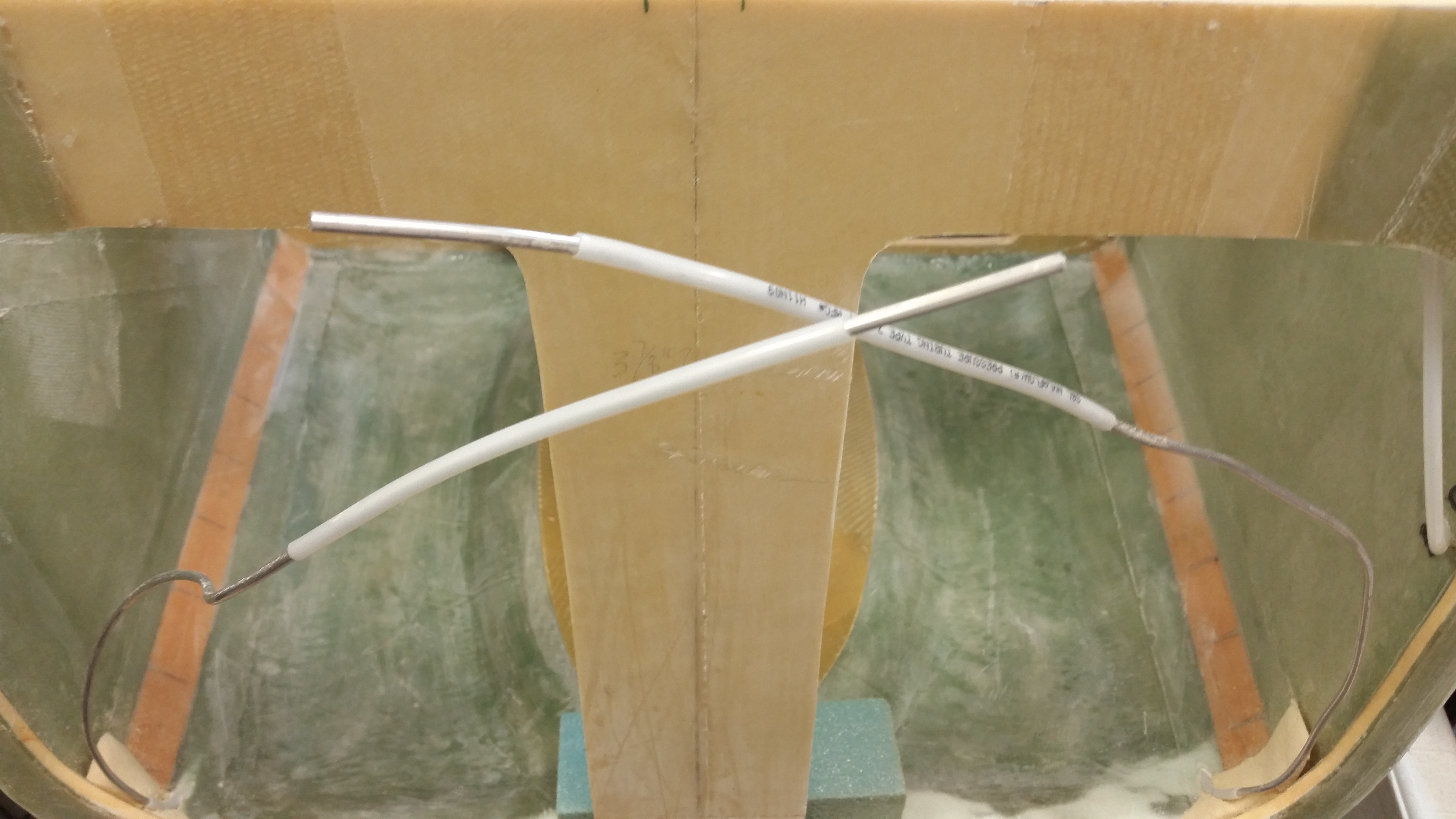
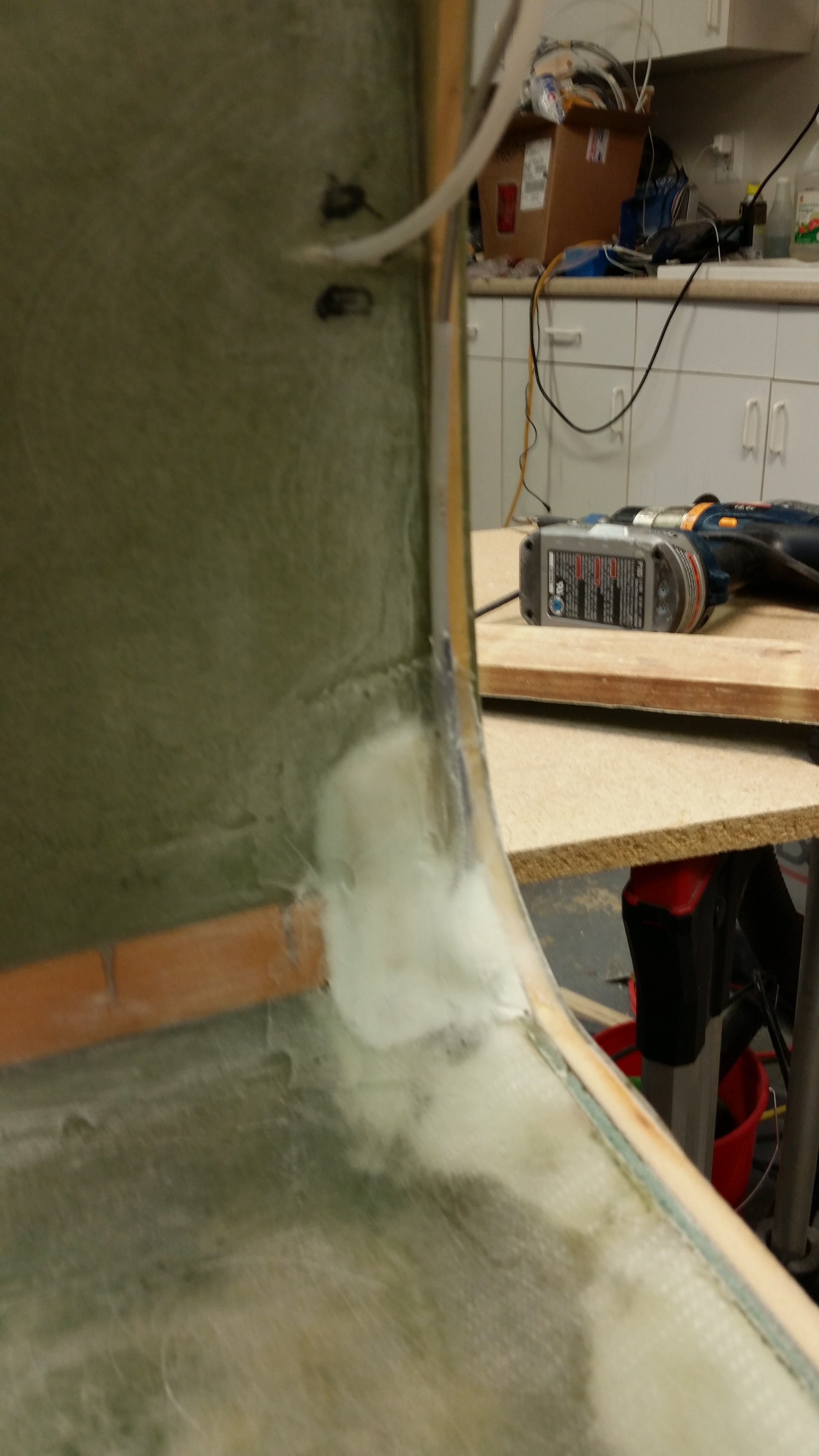
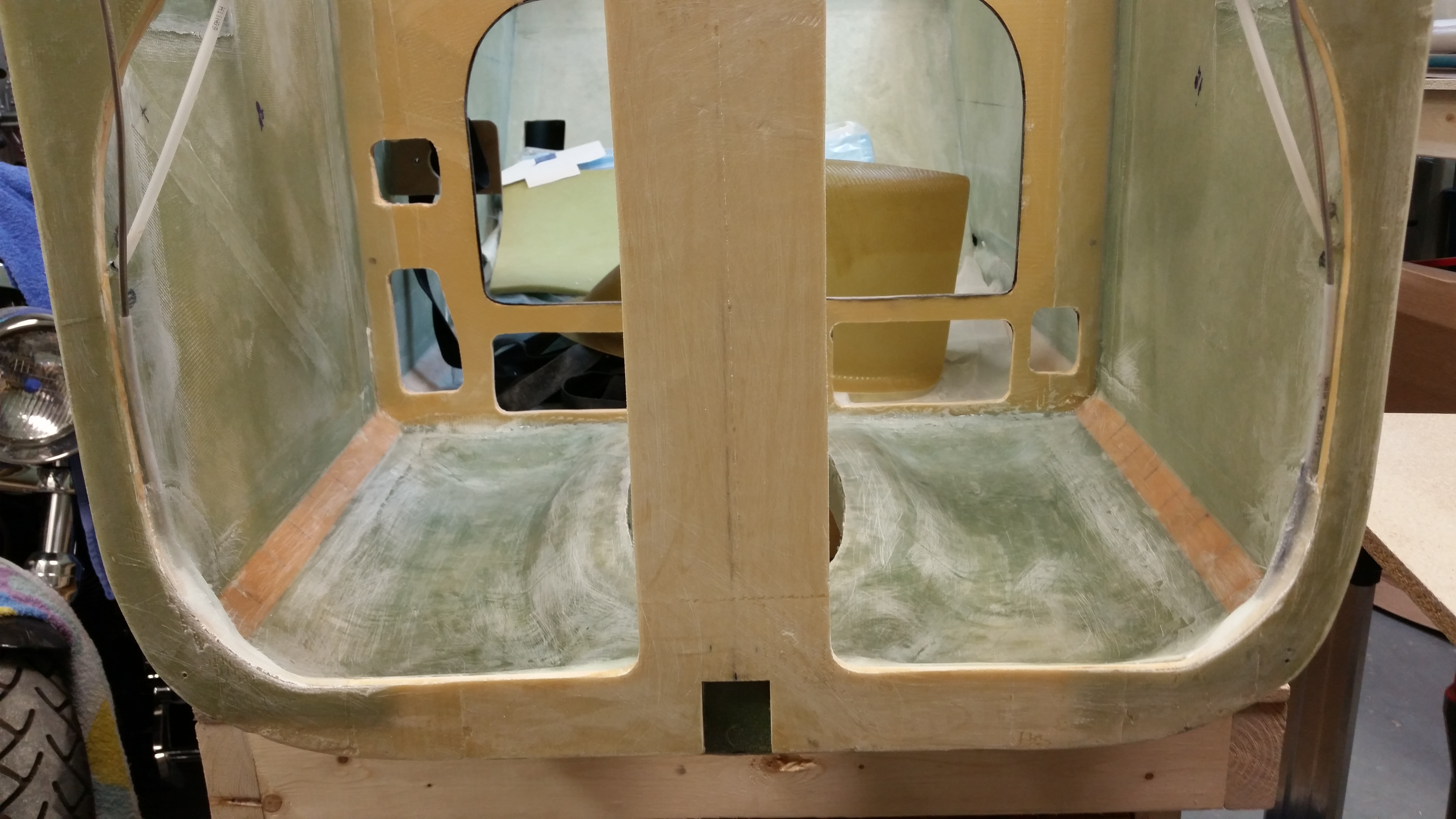
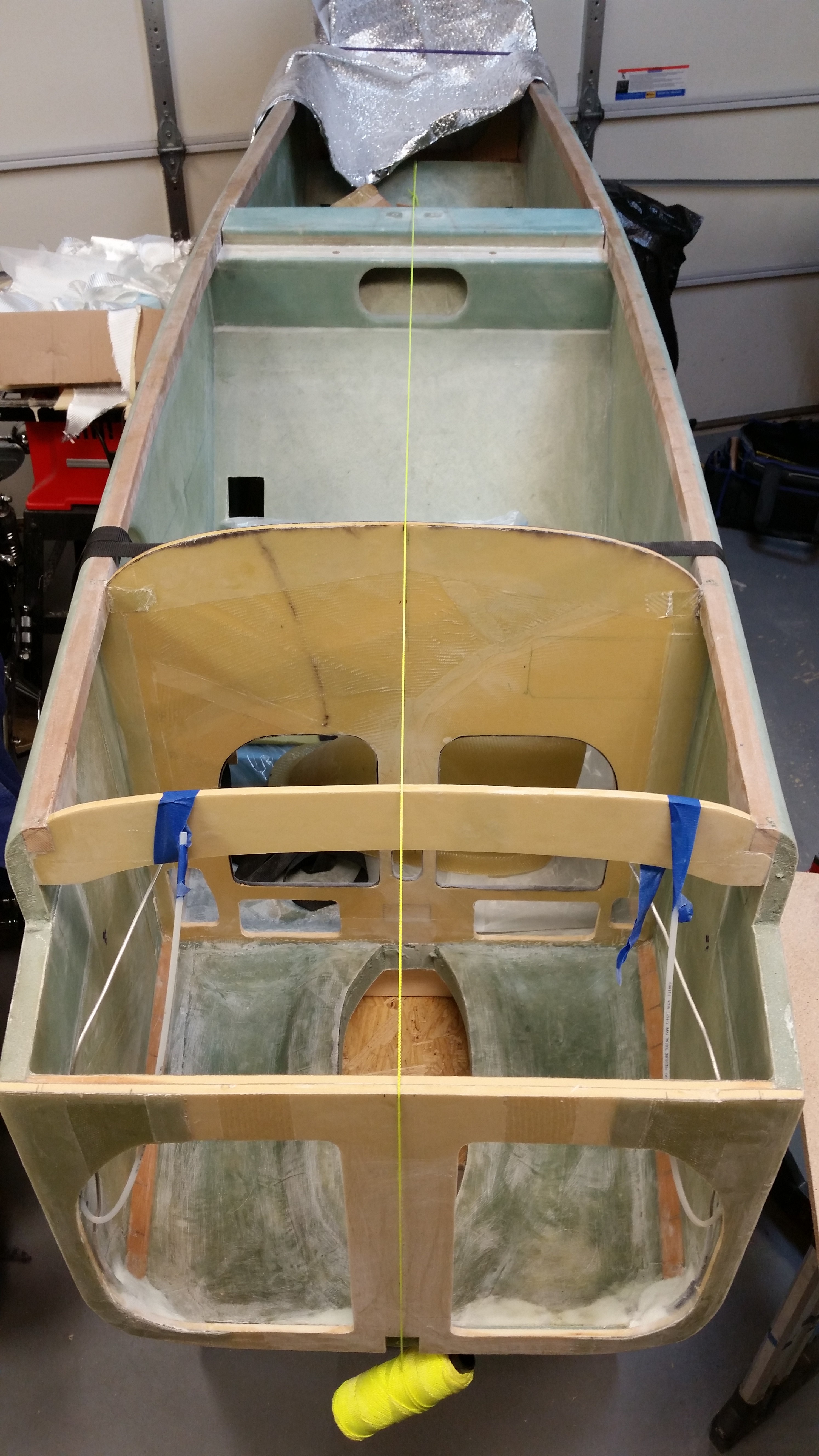
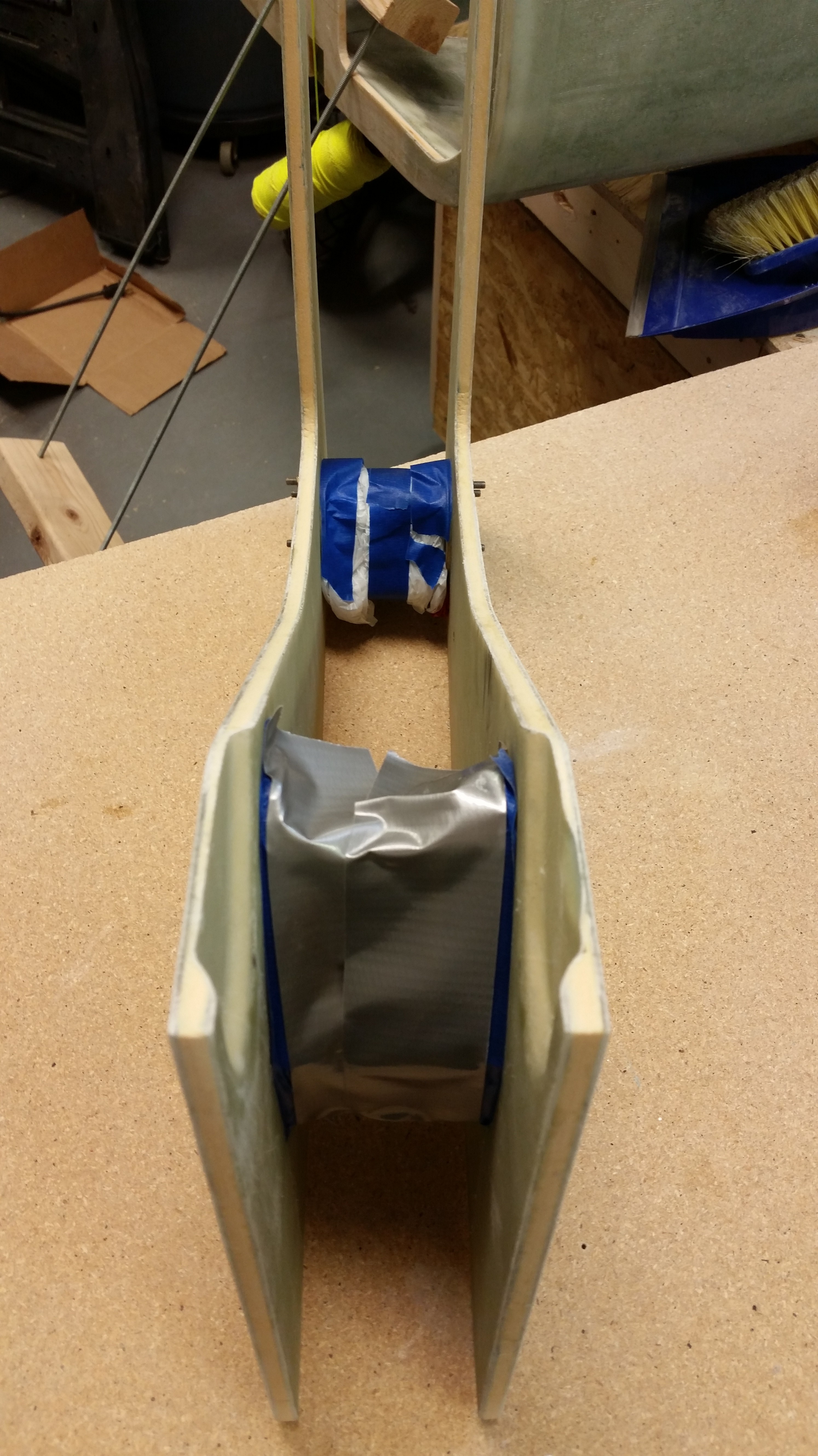
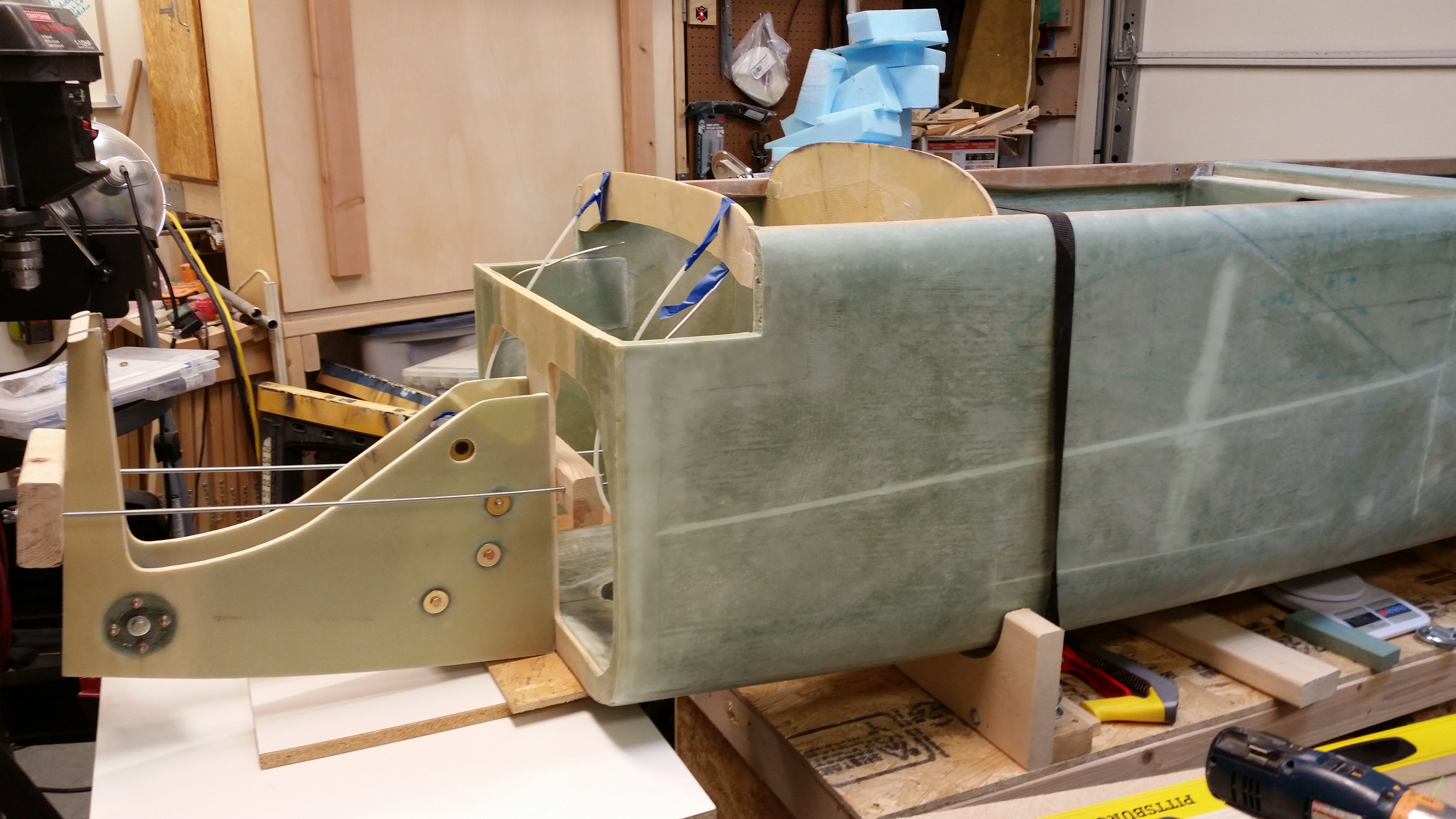
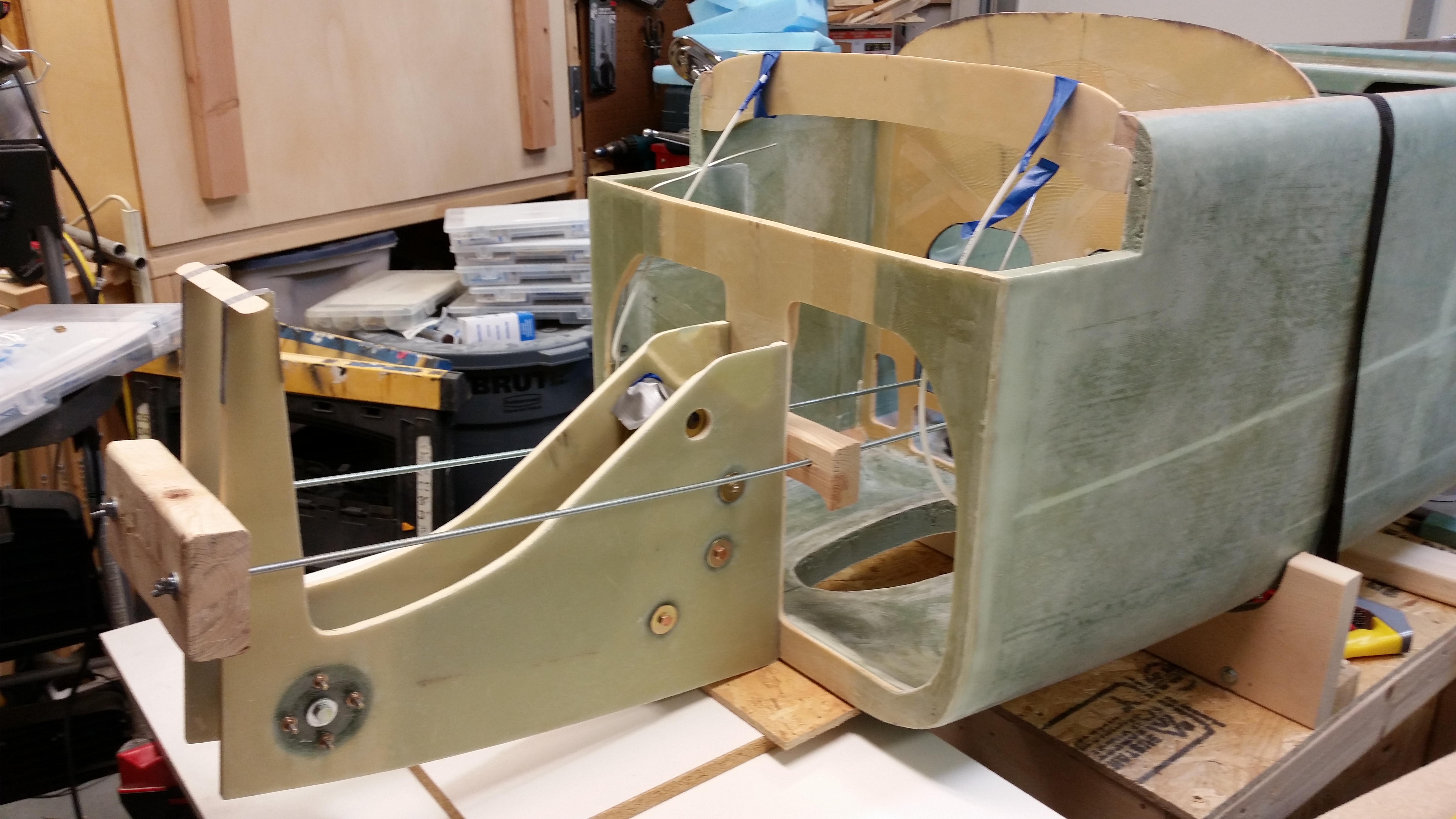
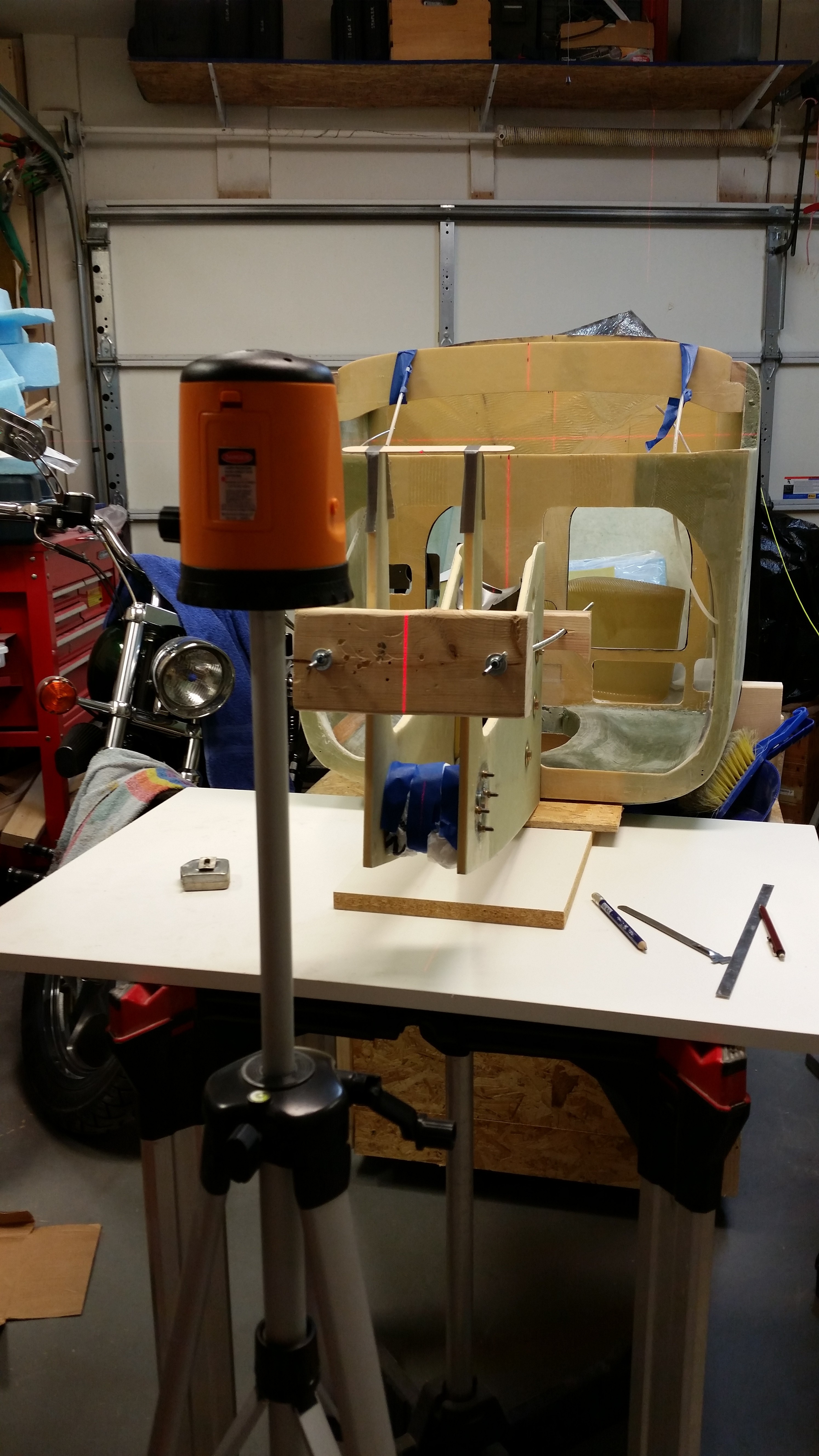
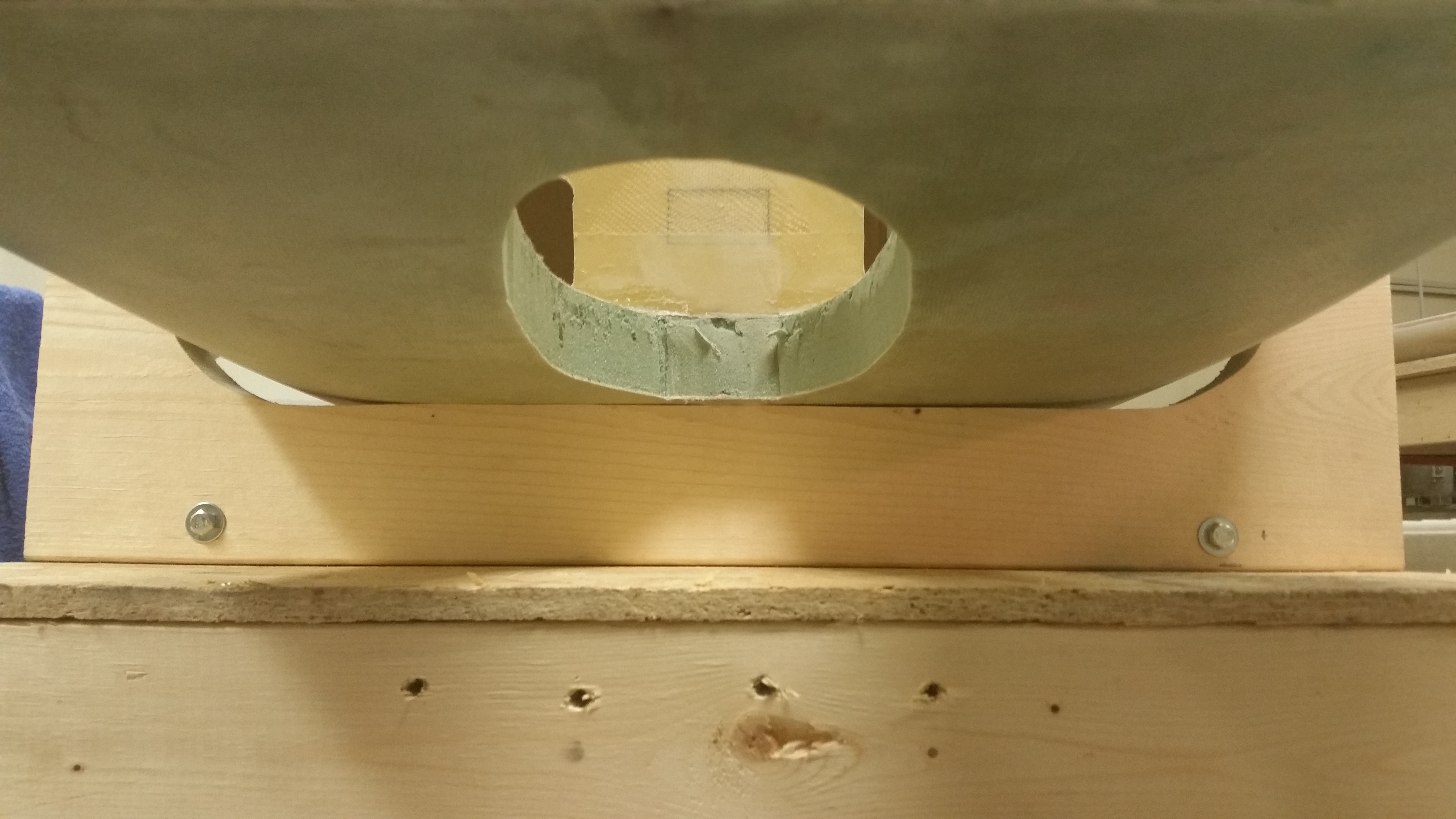
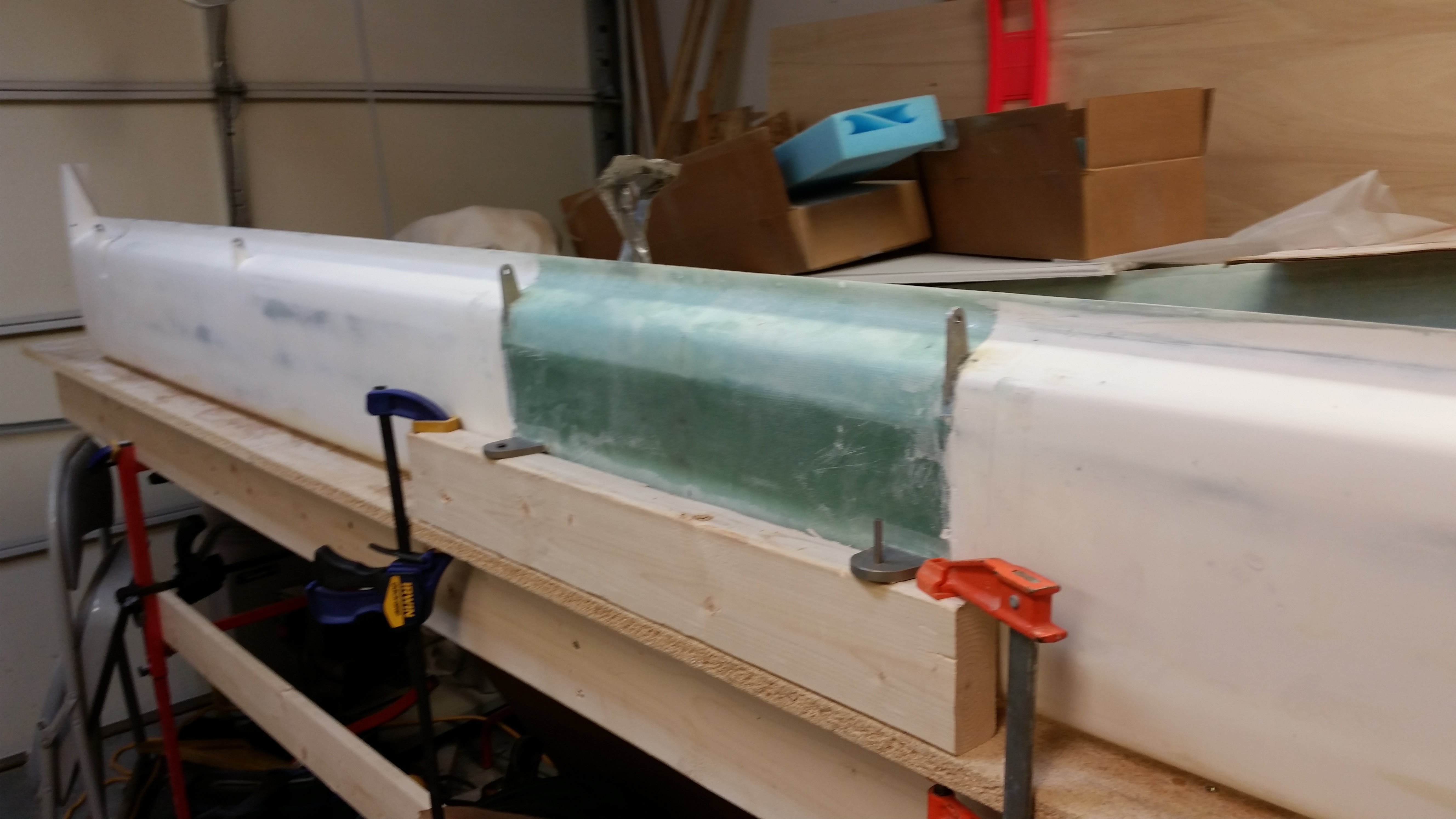
Here’s a couple of shots of the F1-3 bulkhead (“Napster”) attached to the NG30 nose gear box without the clamps.

Napster bulkhead attachedNapster bulkhead attached

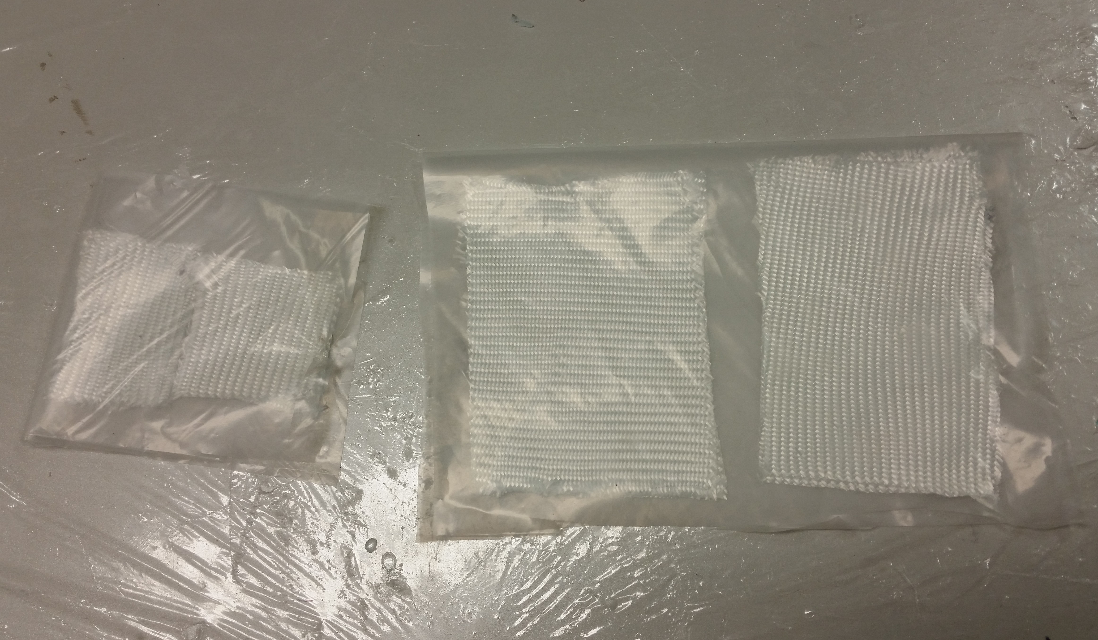
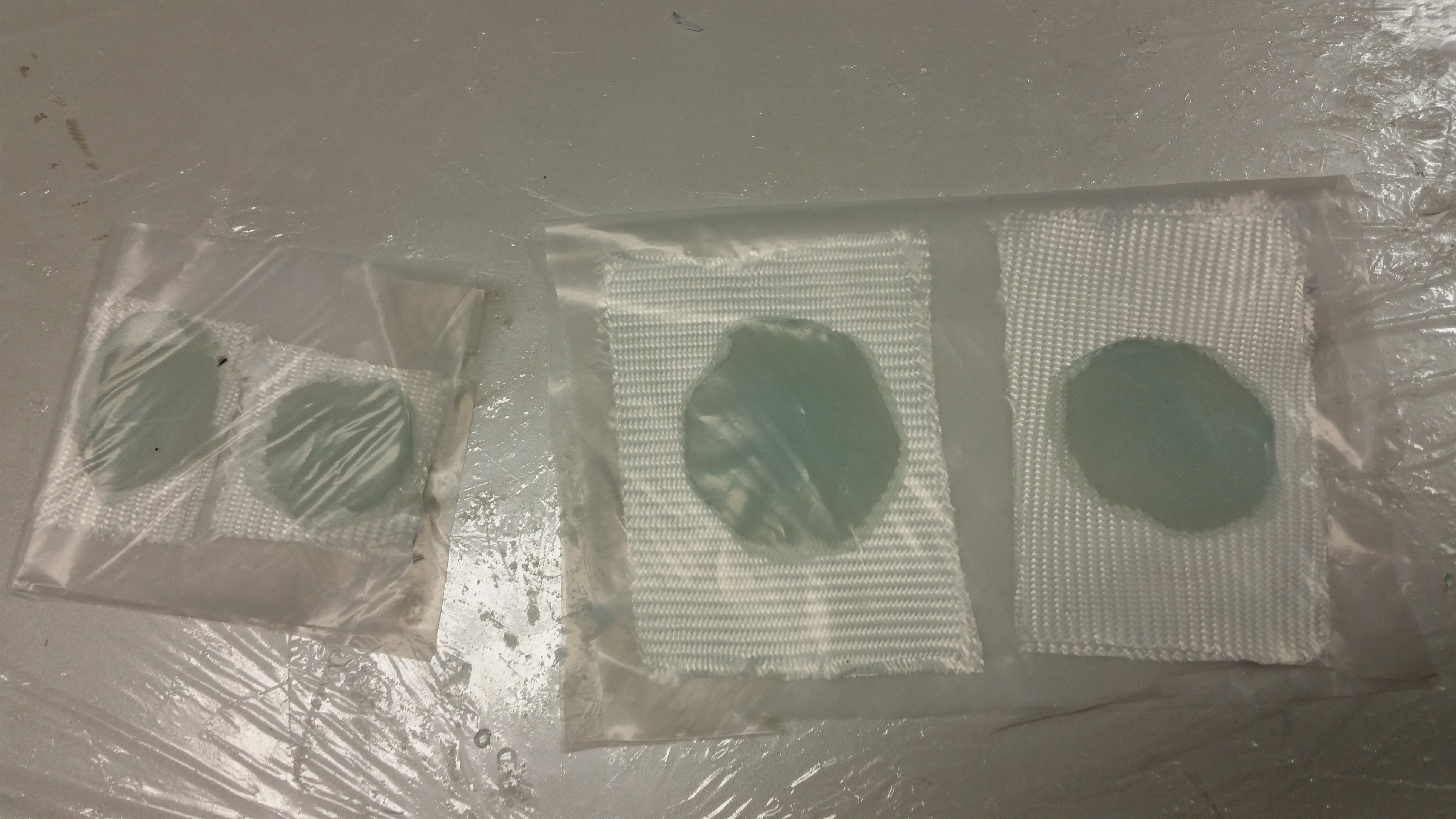
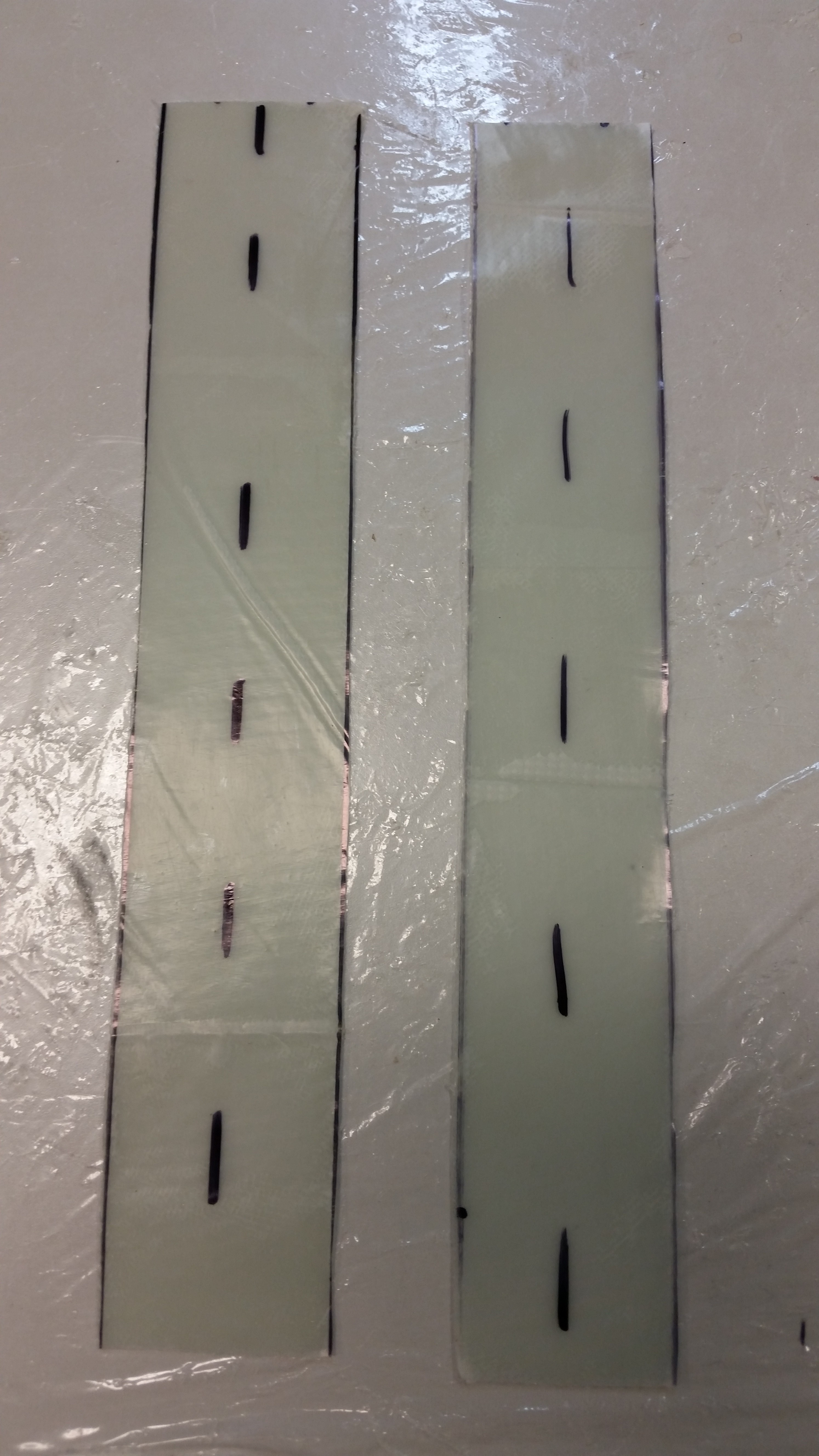
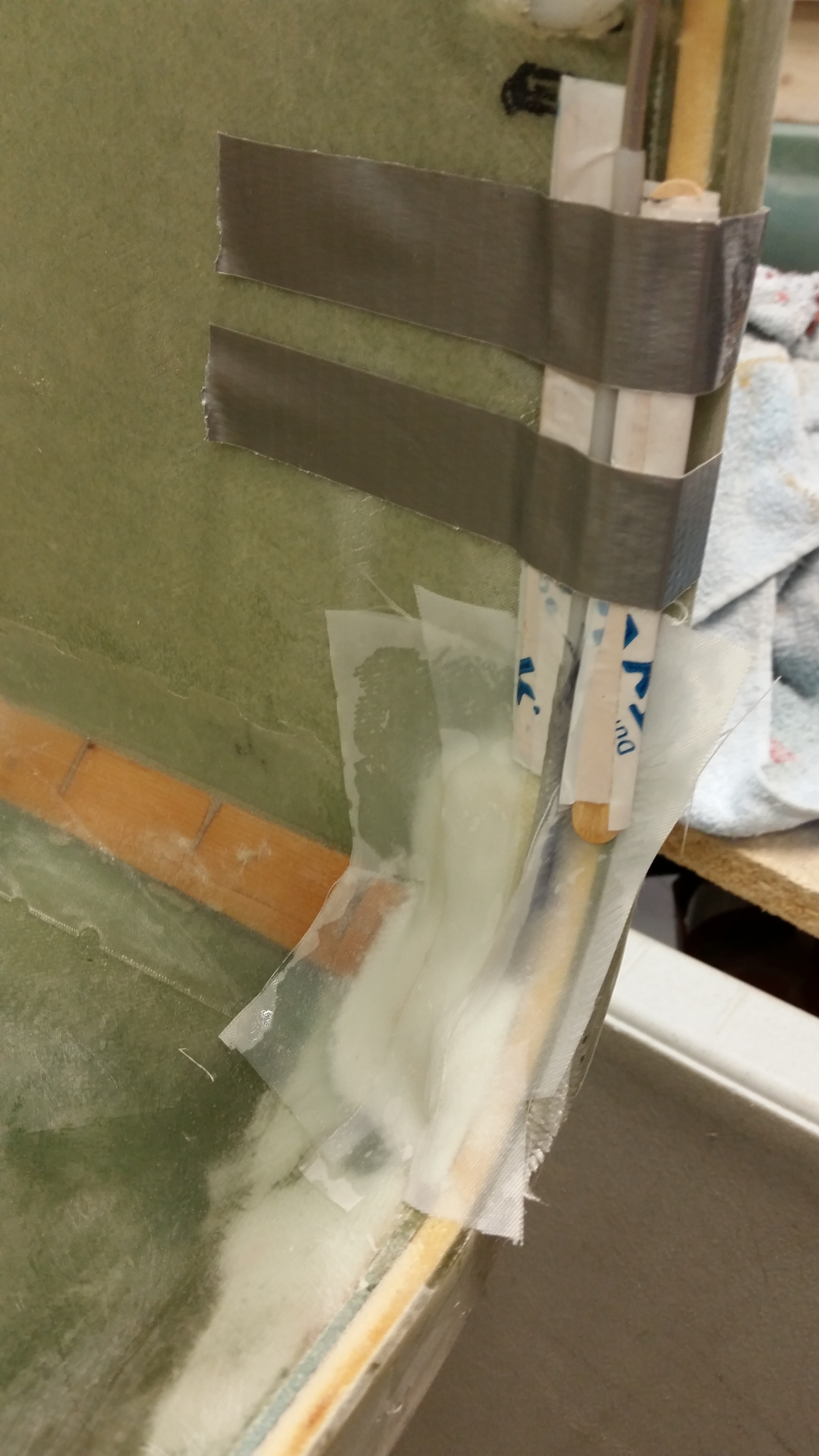
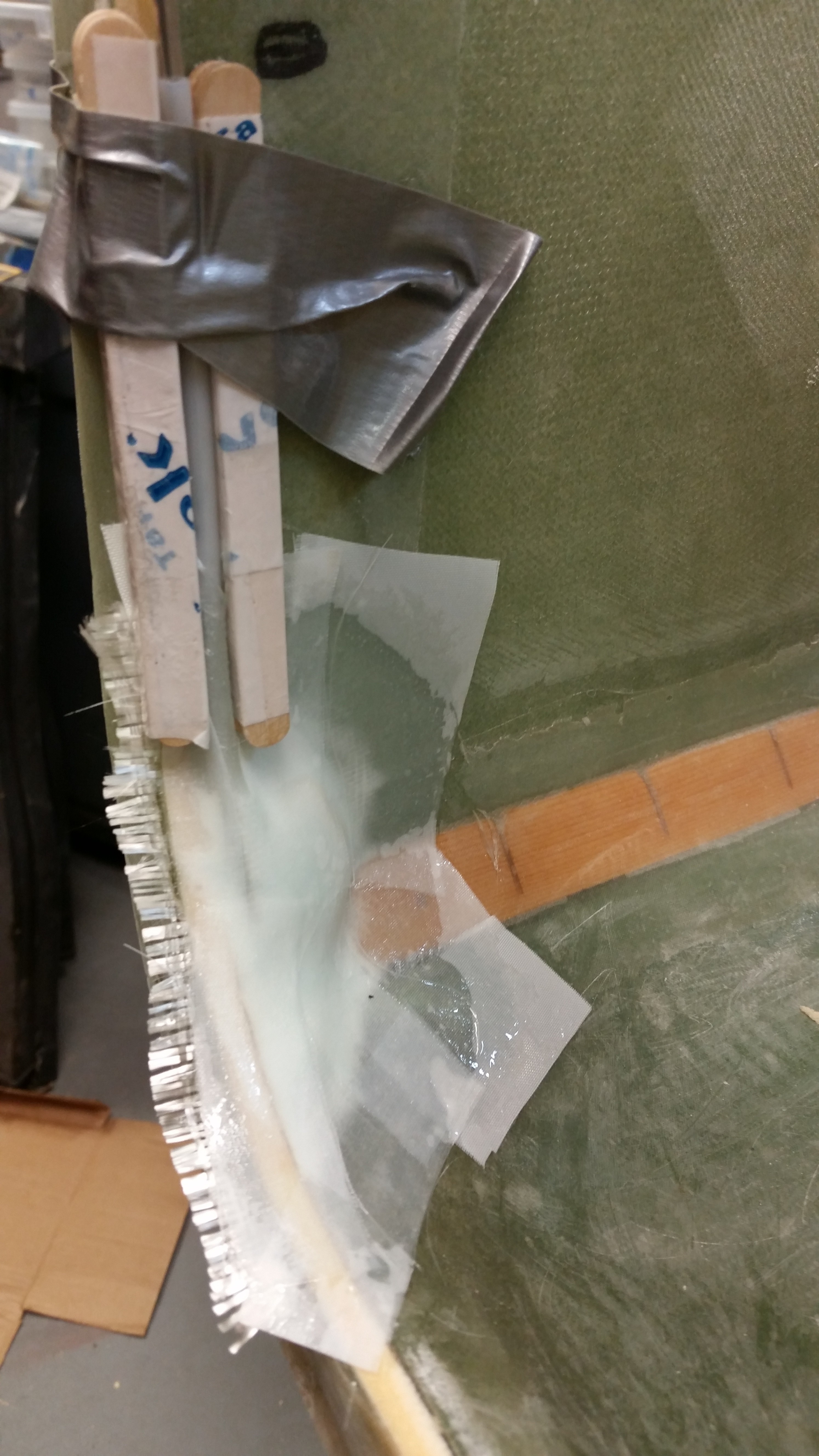
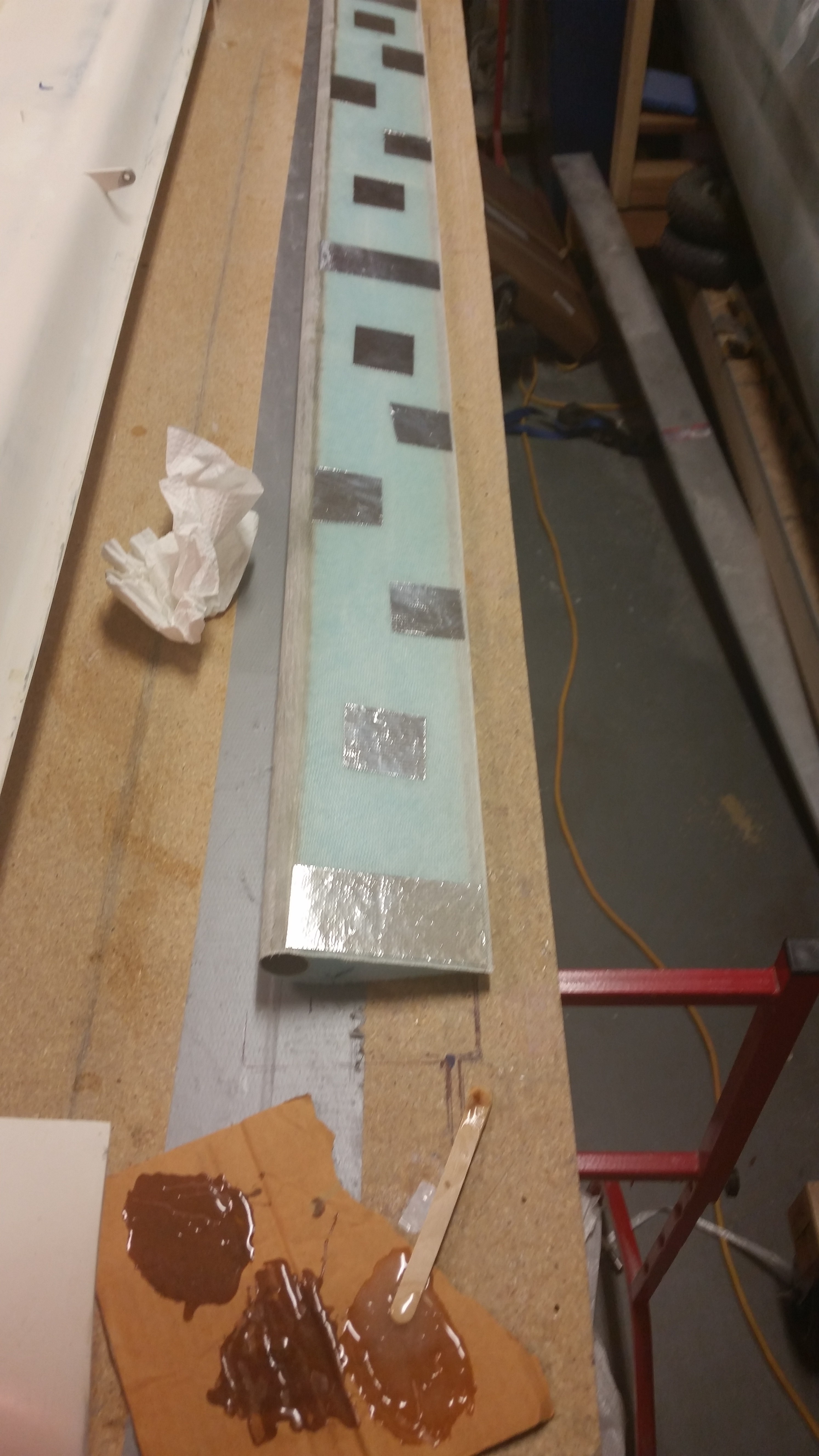
After prepping the prepreg setups for the inboard NG30 uprights-to-Napster BID tapes, I then mixed up some more epoxy with fast hardener for laying up the inboard (NG30 uprights) BID tapes.

Prepregged BID tapesNapster BID tapes

Below are shots of the flox fillets and the laid up BID tapes for the inboard BID tapes.

Inboard Napster flox

Napster BID tapes laid up

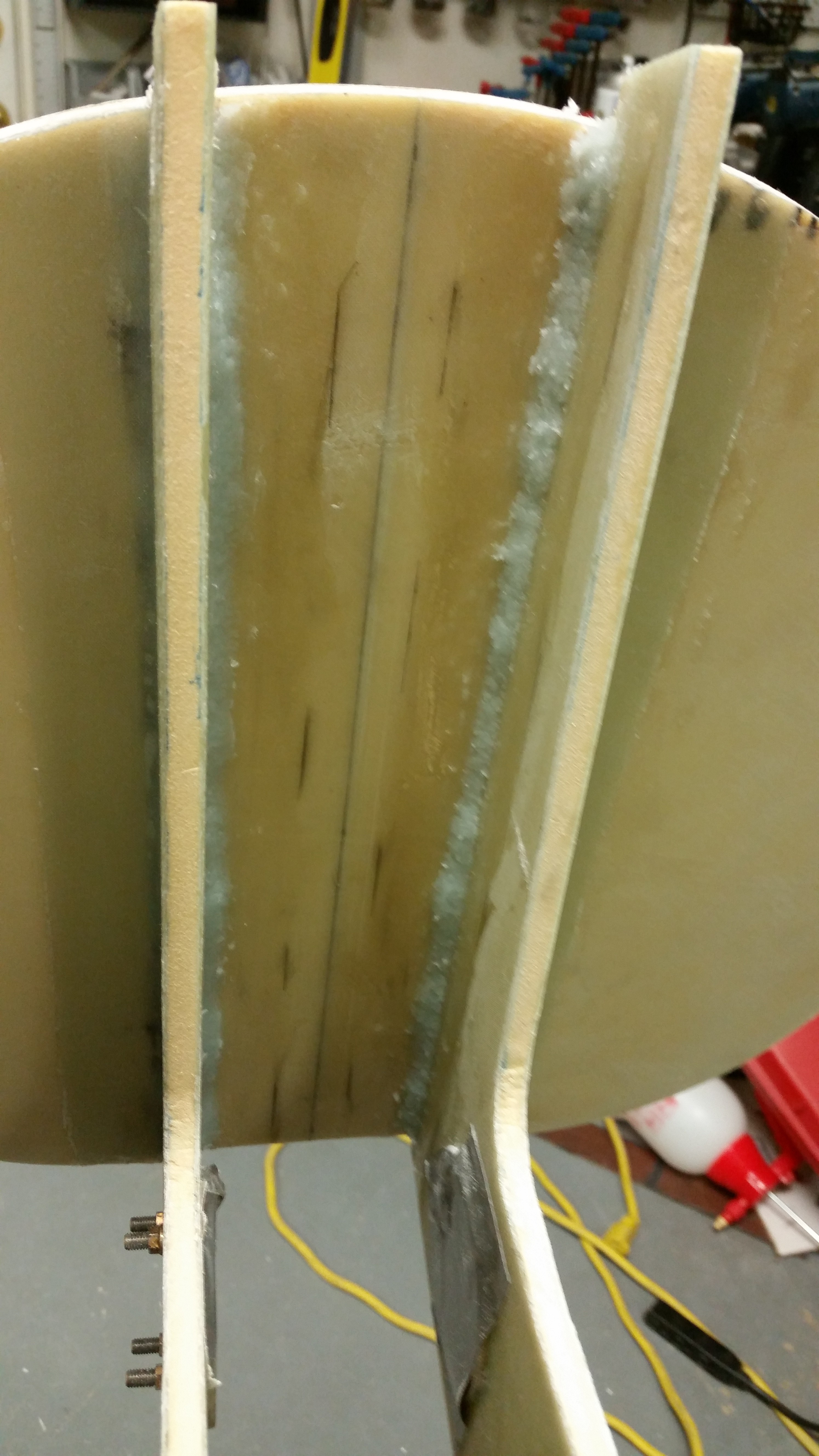
Here’s a shot of the final layup for the inboard BID tapes.

Inboard NG1-3 BID tapes

After laying the inboard NG30 BID tapes, I turned my sights on mounting the nose gear strut to the NG6B nose gear pivot.

Permanent strut mount to NG6B

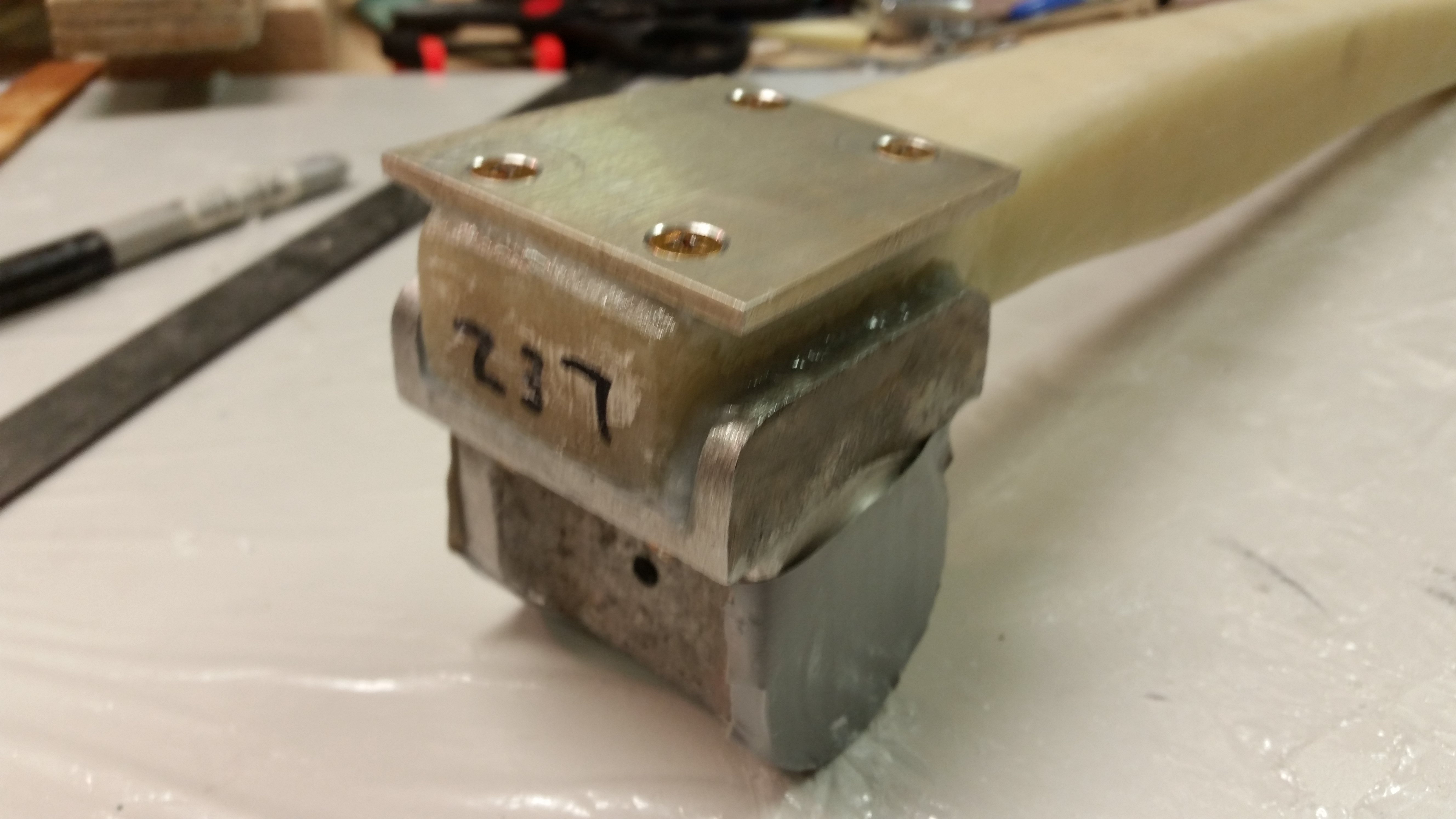
I slathered on a bunch of flox all over the mating parts, then permanently screwed the NG5 (top) plate to the nose great strut and NG6B pivot assembly (bottom).

NG6B flox/screwed to gear strut

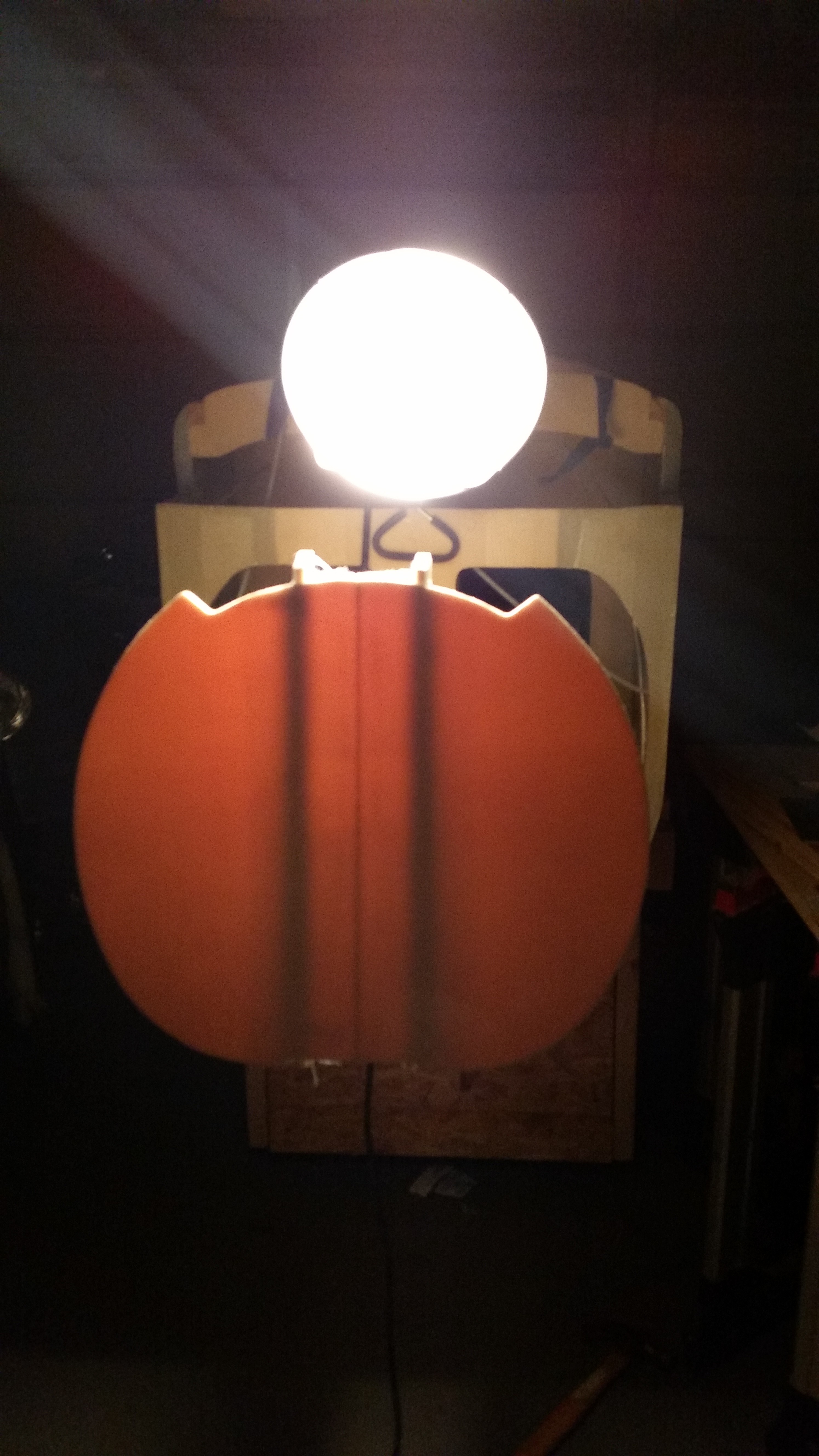
Although a little late for Halloween, this is a shot of “Scary Napster”.

Scary Napster!

Tomorrow I’ll be working both the elevators and the nose build.


Chapter 13 – Getting Nosey!

I started out today by setting up the prepreg BID for the lower half of the NG30 to F22 layup.

Lower exterior NG30 PrePreg setup

I mixed up some epoxy with fast hardener and wetted out the prepreg BID.

Lower exterior NG30 PrePreg

And then mixed up some flox and applied it to the corners.

Epoxy applied to lower half corner

Below is a shot of the 2-ply BID prepreg layup for the right external NG30 to F22 attach.  I overlapped the bottom layup over the first (top) layup by an inch.

Right lower NG30 glassed

I then peel plied the layups.  Note that I also laid up 2 plies of BID in the very bottom corner between the NG30 plate and the F22 plate.

Lower NG30 assembly peel plied

While the NG30 glass was curing I started working on mounting the fuselage further forward on the fuselage dolly so that there would be plenty of clearance for the front wheel ingress & egress from the nose gear wheel well.

Current fuselage dolly configuration

Wider fuselage dolly saddle installed

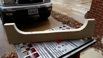
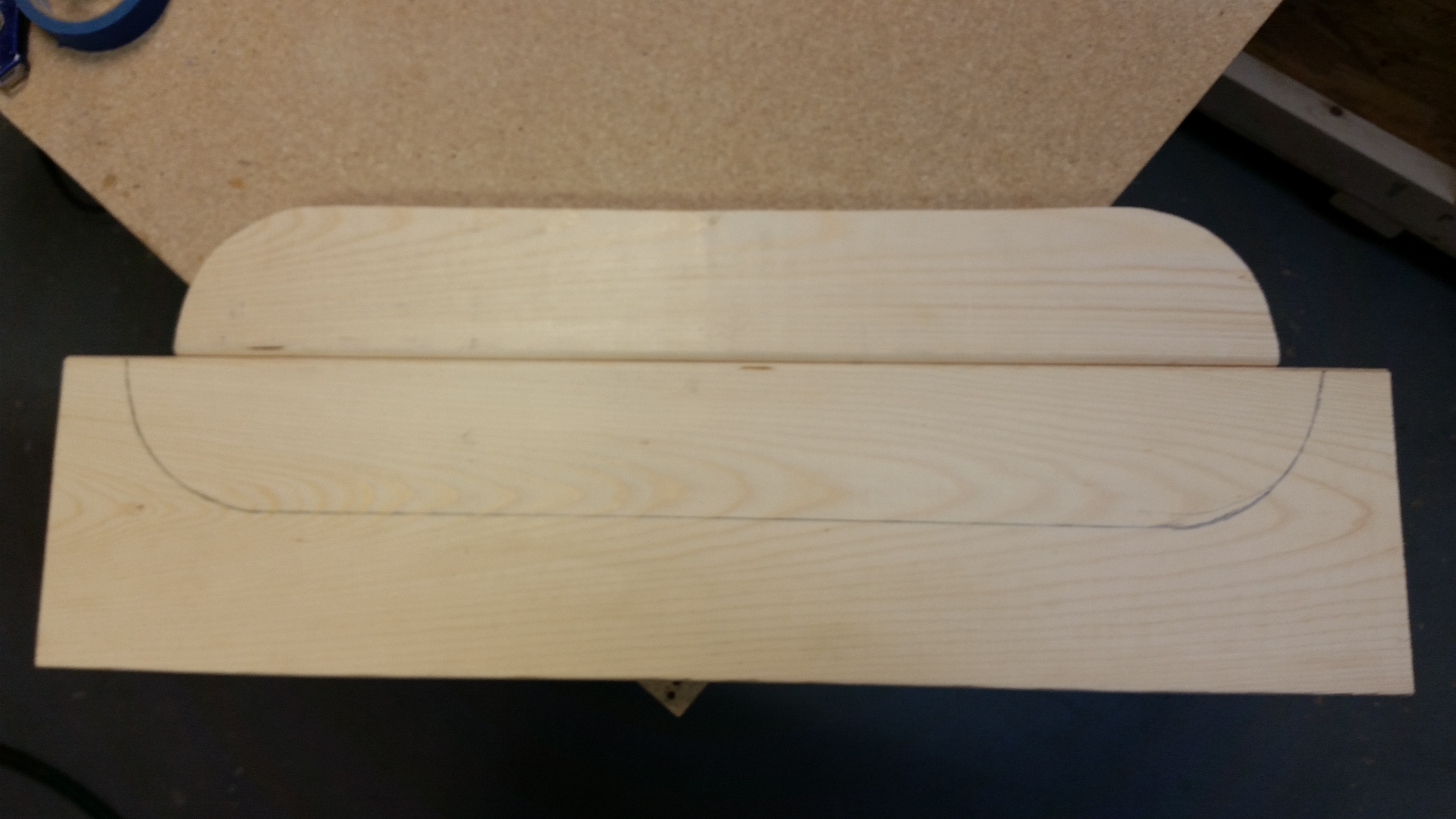
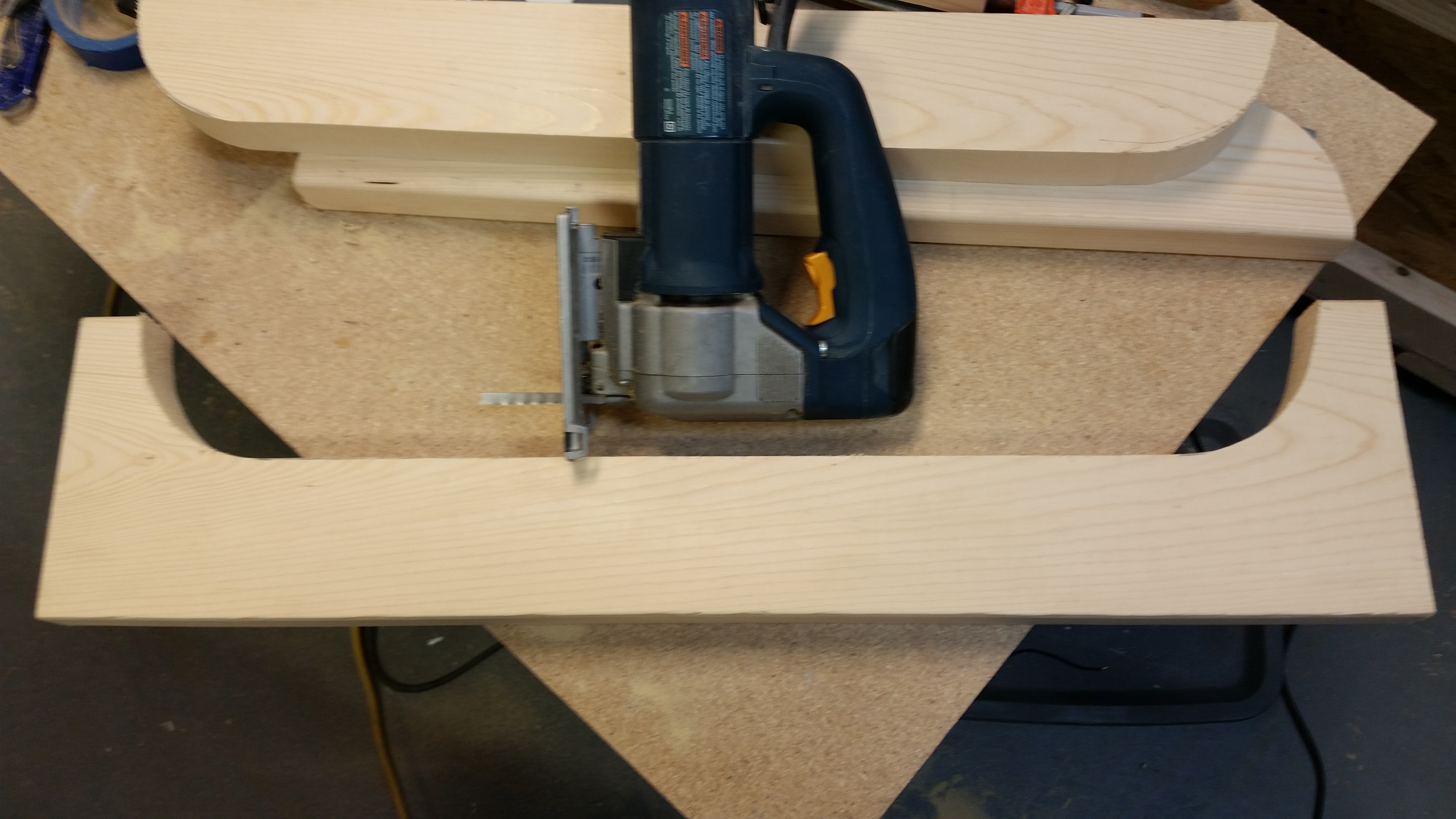
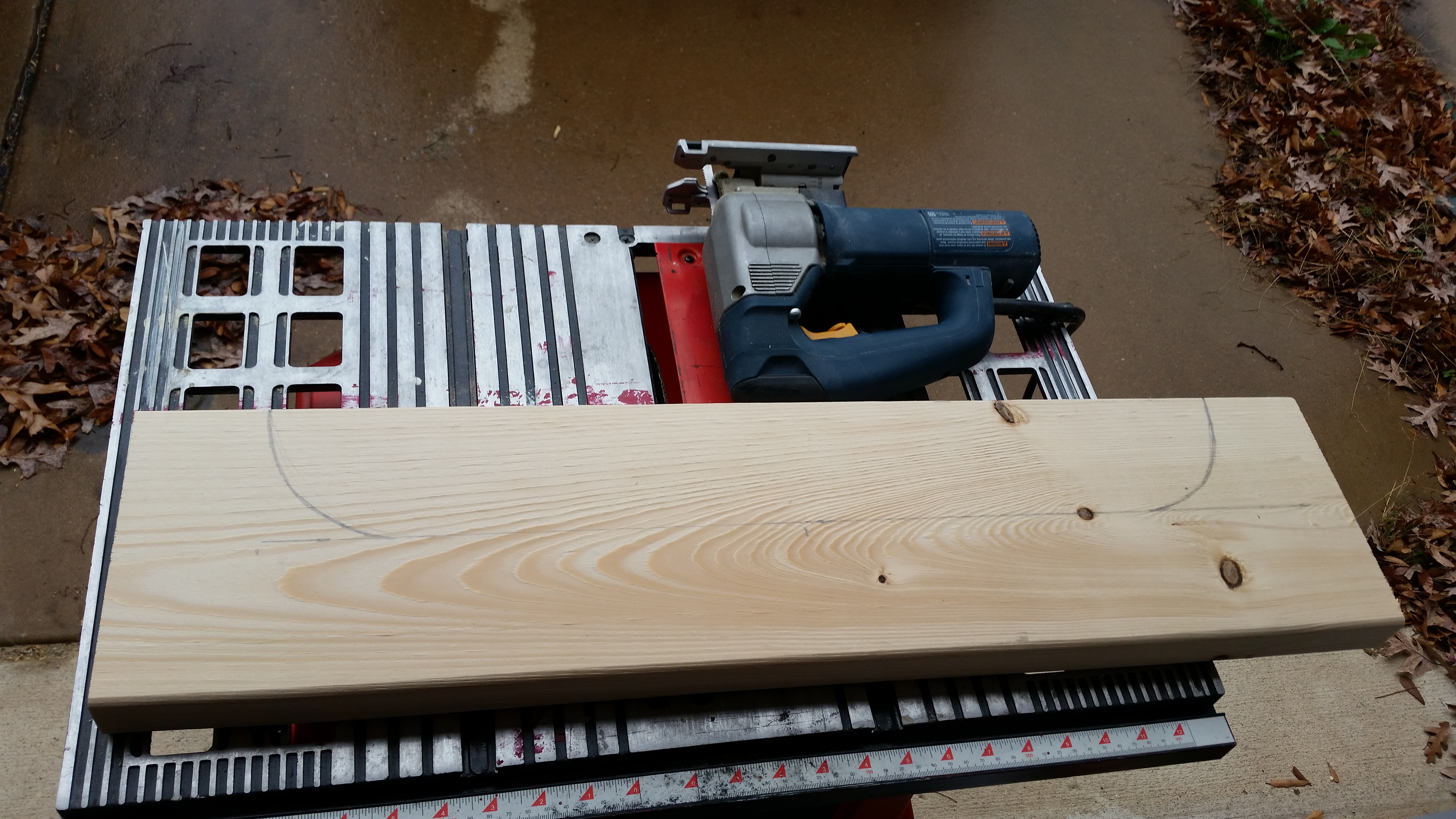
To move the fuselage forward I needed to cut another fuselage saddle wider than the current forward saddle.  I marked up a piece of wood and cut it out.

Wider fuselage dolly saddleWider fuselage dolly saddle

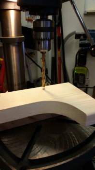
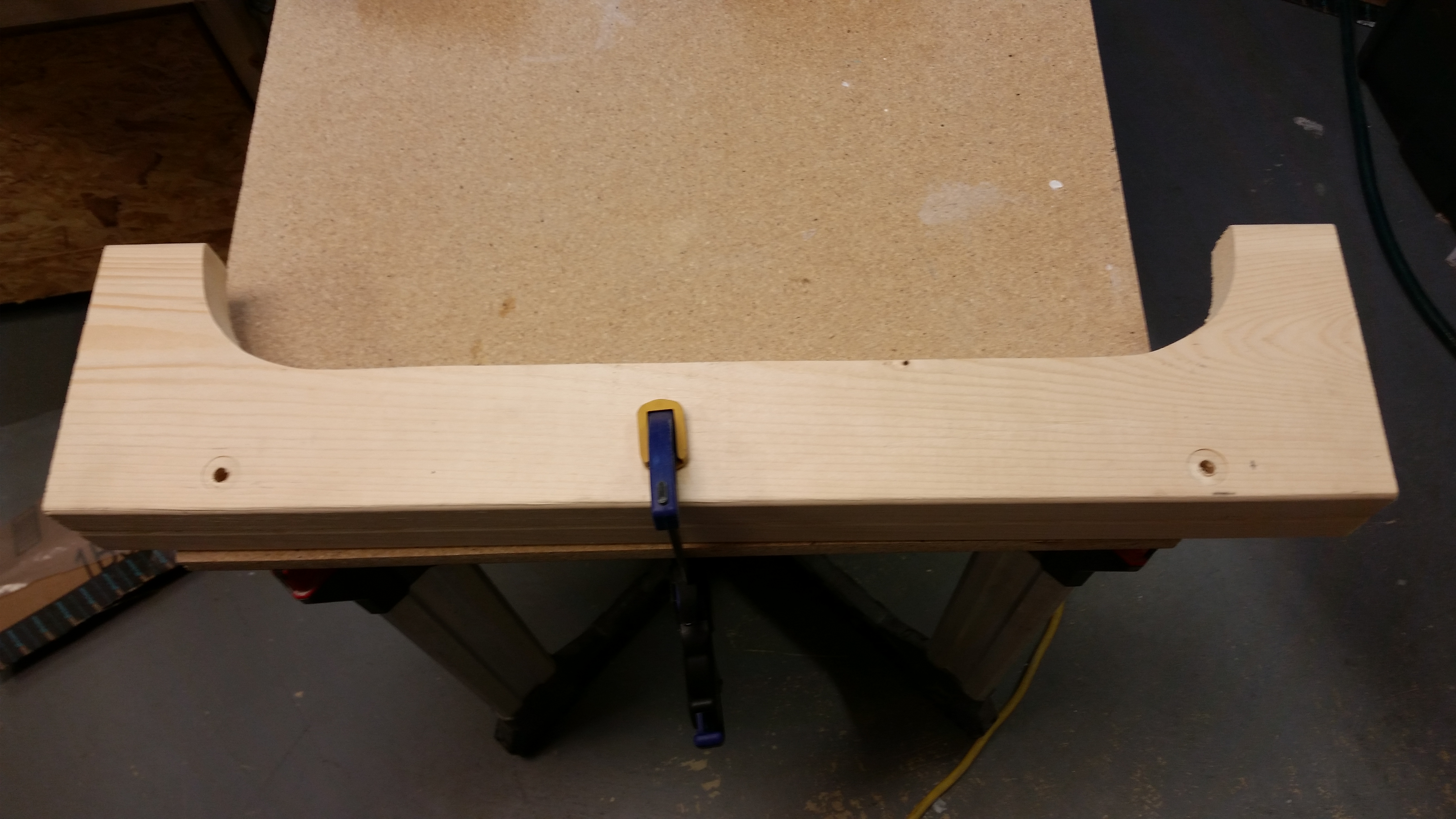
I then clamped the old saddle over the new undrilled saddle.  I drilled through the existing holes to make the new mounting holes.

Wider fuselage dolly saddle

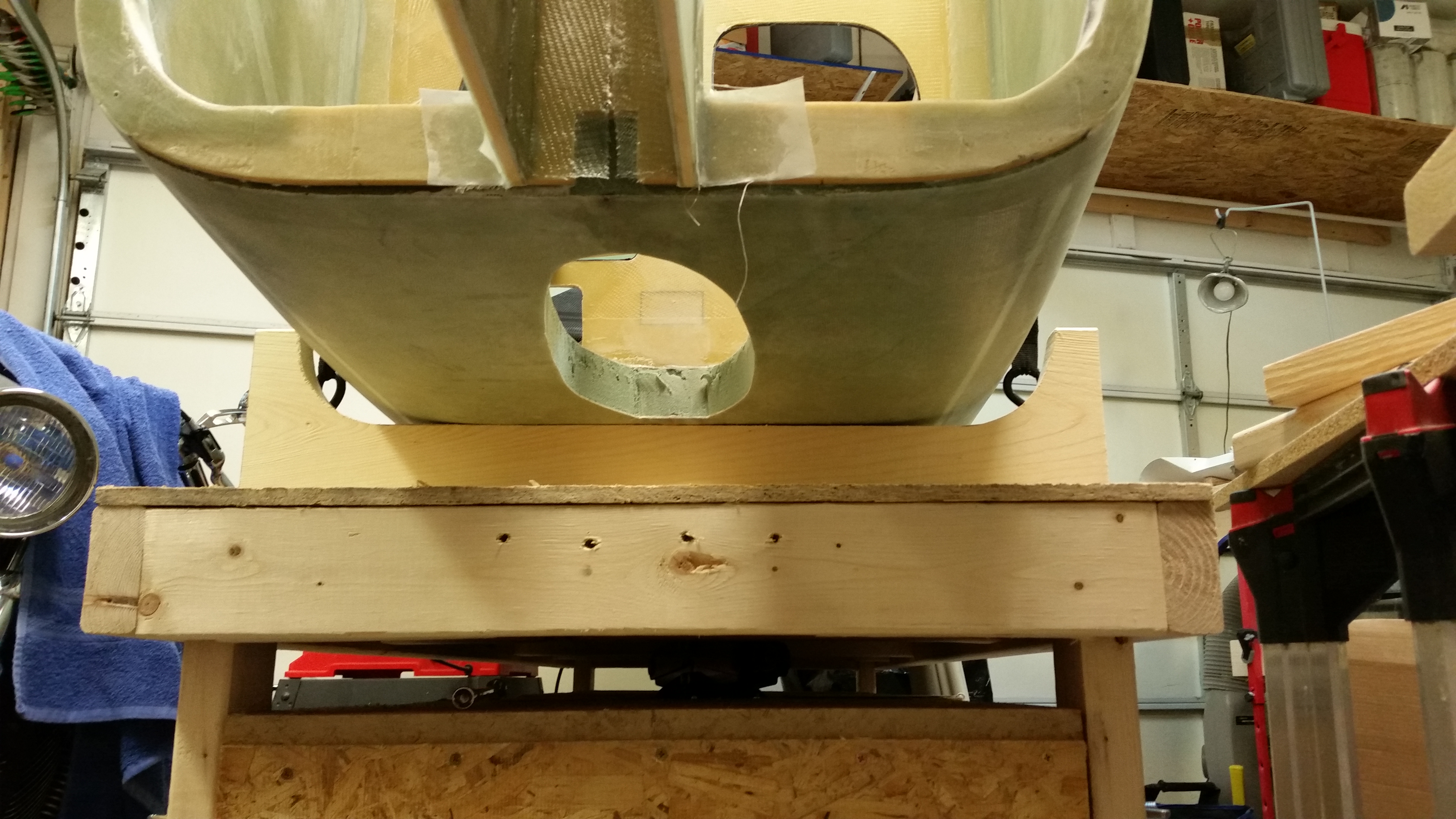
Here’s the new saddle in place and mounted with the 5/16″ bolts…

Clearance for the nose wheel

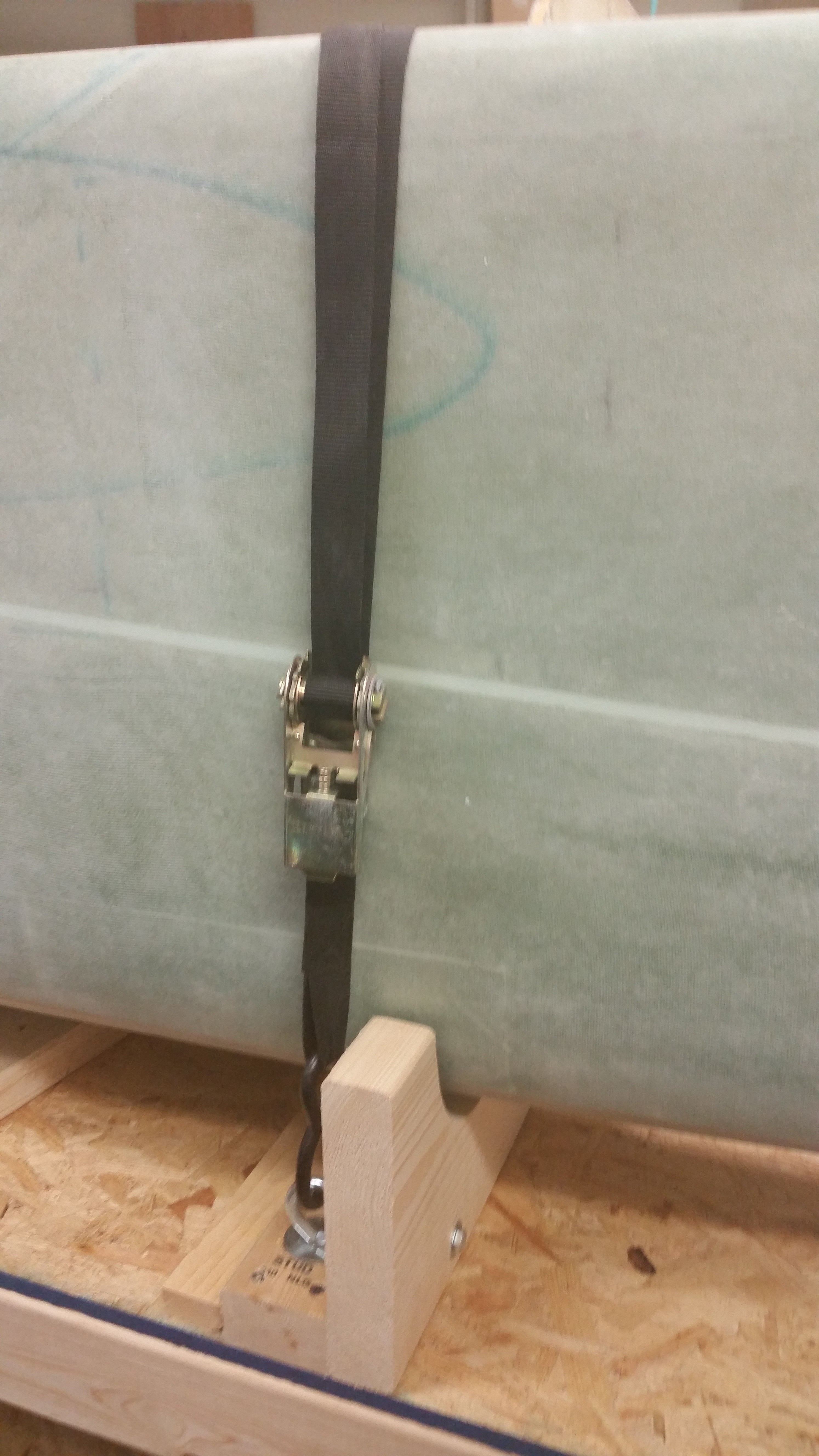
allowing me to move the fuselage farther forward on the dolly.  I also added another tie down strap.

New fuselage dolly configuration

With the nose wheel clearance taken care of I started working on mounting the nose gear strut (NG1-L) to the nose gear pivot (NG6B).  I mounted it temporarily using clamps, and spent a good 20 minutes getting it aligned down the center of the channel.

I also temporarily mounted the nose wheel to ensure their was enough clearance for the wheel in the wheel well.  It was close, but there was just enough clearance aft of the wheel.

Mocking up nose gear strut

Mocking up nose gear strut

Once I got it aligned I loaded my drill with a 3/16″ bit and started to drill starter holes in each of the 4 holes in the NG6B.

I should probably offer a reminder at this point that I’m using Jack Wilelmson’s NG6B vs the NG6A (or the original NG6).  The NG6B differs in that it uses two separate bolts to hold it in place –one from each side– rather than the single long bolt that the NG6A uses.  This comes in rather handy if you want to remove the nose gear pivot after the nose is built.  Unfortunately, the NG6A bolt can’t be removed easily after it’s installed since the bolt is too long.

The NG6B also comes with the 4 screw holes pre-drilled which makes it really nice when it comes to this part of the build!

Mocking up nose gear strut

My initial plan was to simply drill some starter holes since that would give me the exact locations of the screw holes.  I would then finish drilling the holes on the drill press later.  Well, as I was drilling the starter holes, it occurred to me that the bottom of the nose gear strut isn’t straight, level or even, so mounting this horizontally & level on the drill press table would not be an EZ endeavor.  So, in the name of optimizing time and getting this done I went into Maverick mode and just finished drilling the holes with the power hand drill, freestyle.

Mocking up nose gear strut

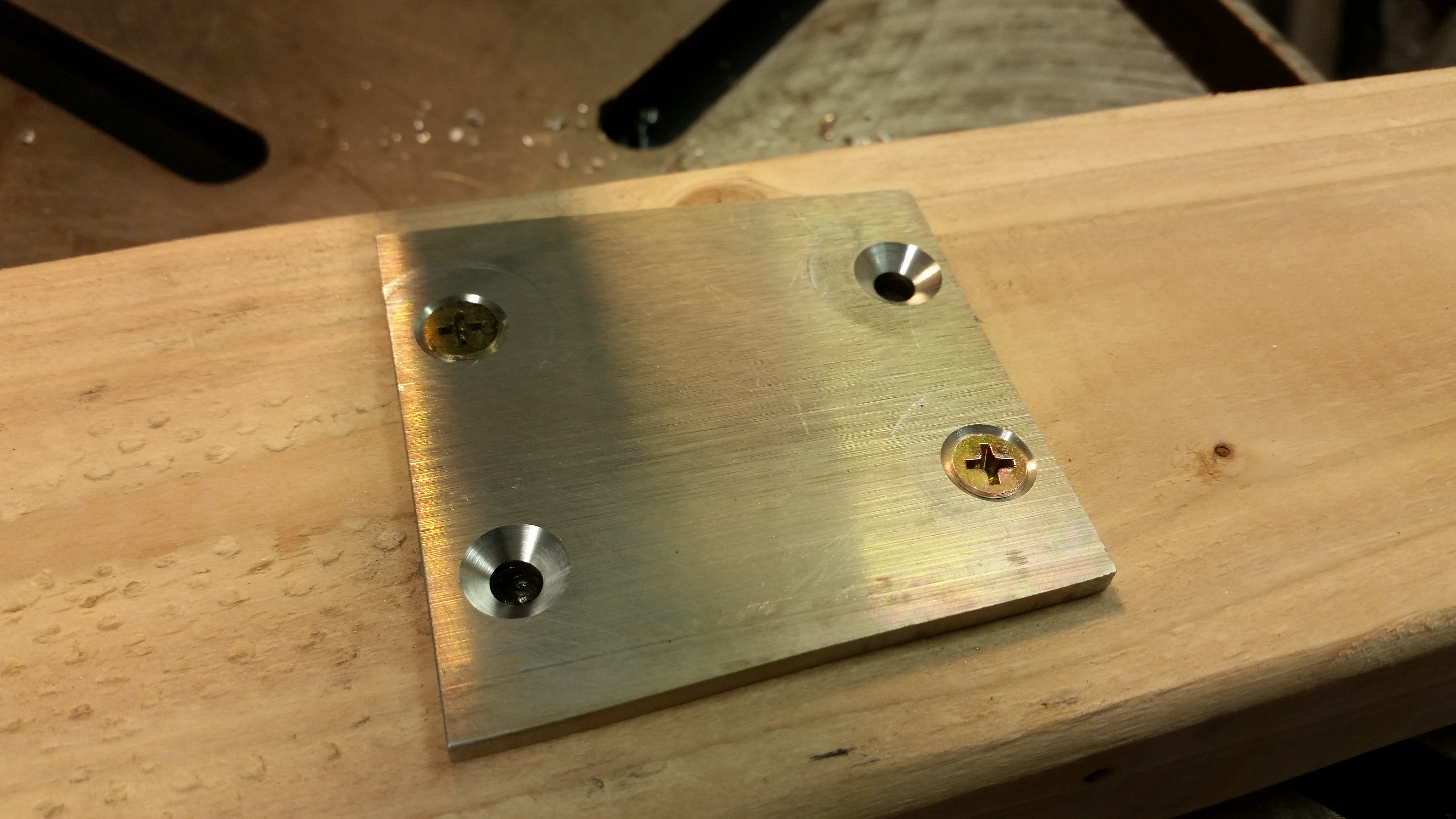
Now, I did use the drill press to drill the countersinks into the NG-5 plate.  I screwed the NG-5 down to a 2×4 with 2 screws.  I then drilled the first two countersinks, swapped the screws and drilled the last two countersinks.

Cutting counter sink holesCutting counter sink holes

Here’s the finished NG-5 plate screwed in place to the nose gear strut.  The ring around the lower left screw in the pic below is because by using the countersink drill bit assembly on the drill press obviously works differently than using it on a hand drill, where with the latter when you press down on the plate it stops the support plate on the drill bit.  When using it on a drill press you have to manually stop the support plate from spinning before engaging the actual bit.

NG5 plate attached

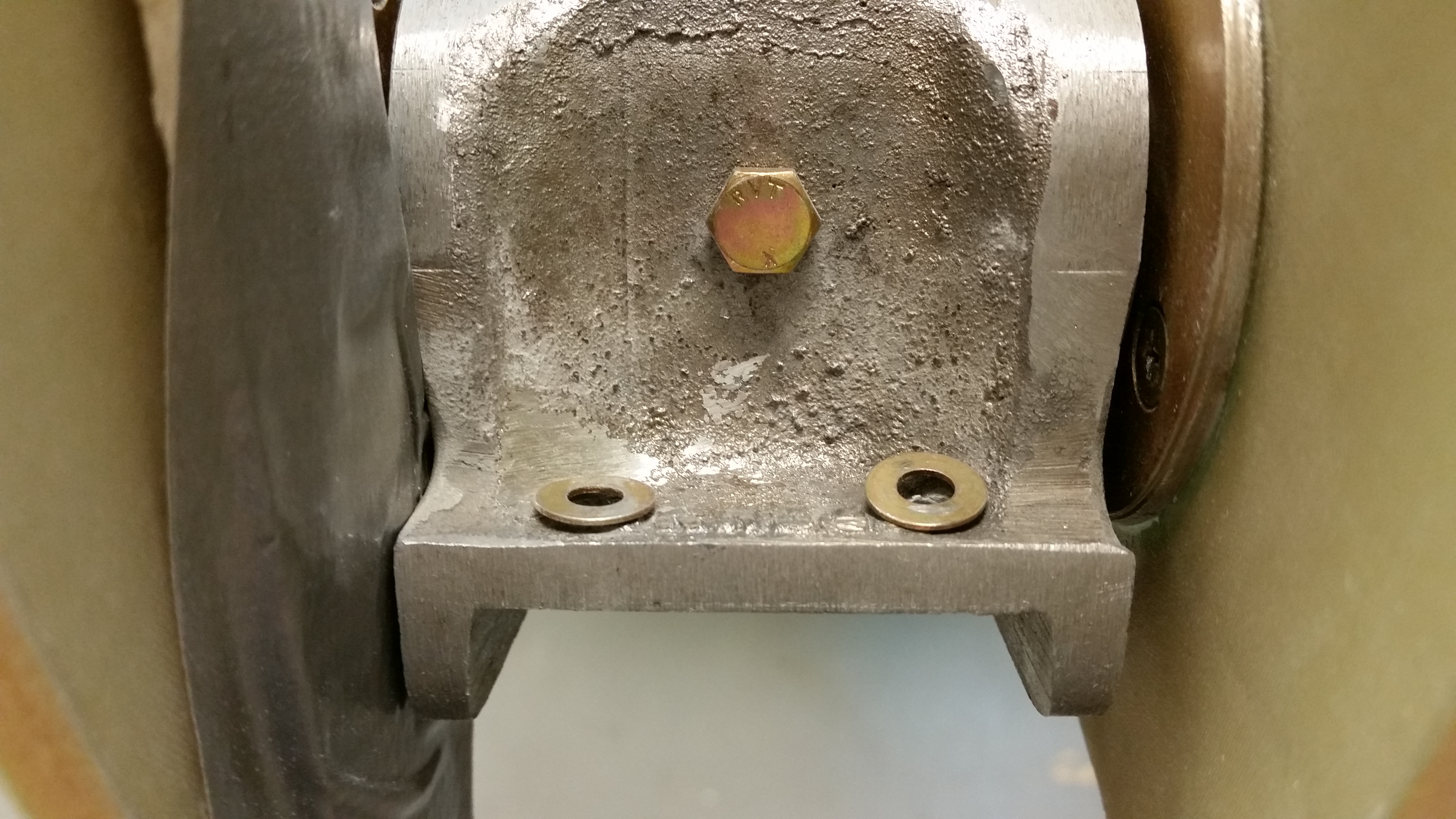
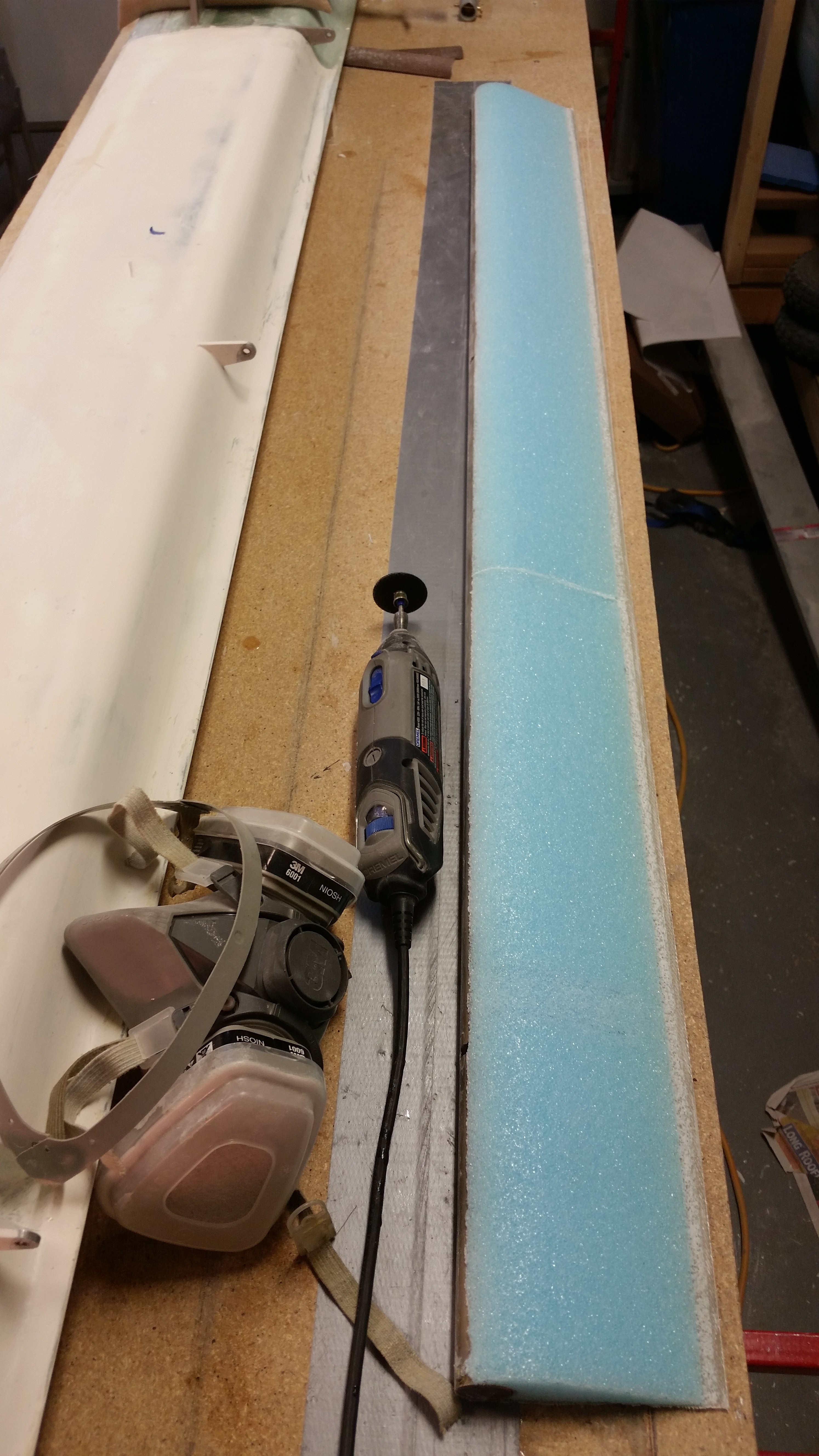
All NG6 assemblies seem to require that the areas around each screw hole be ground down to allow the washers & nuts to fit.  Below you can see that I Dremeled out the area around the hole on the left, while the hole on the right was not yet completed.

Grinding NG6 for washer/nut fit

The aft holes seemed to be ok for now, so I just added some temporary nuts and tightened everything up.  It all lined up great.

Nose gear strut attached to NG6

Here are a couple of shots of the nose gear strut in place.

Nose gear strut attached to NG6

Nose gear strut attached to NG6

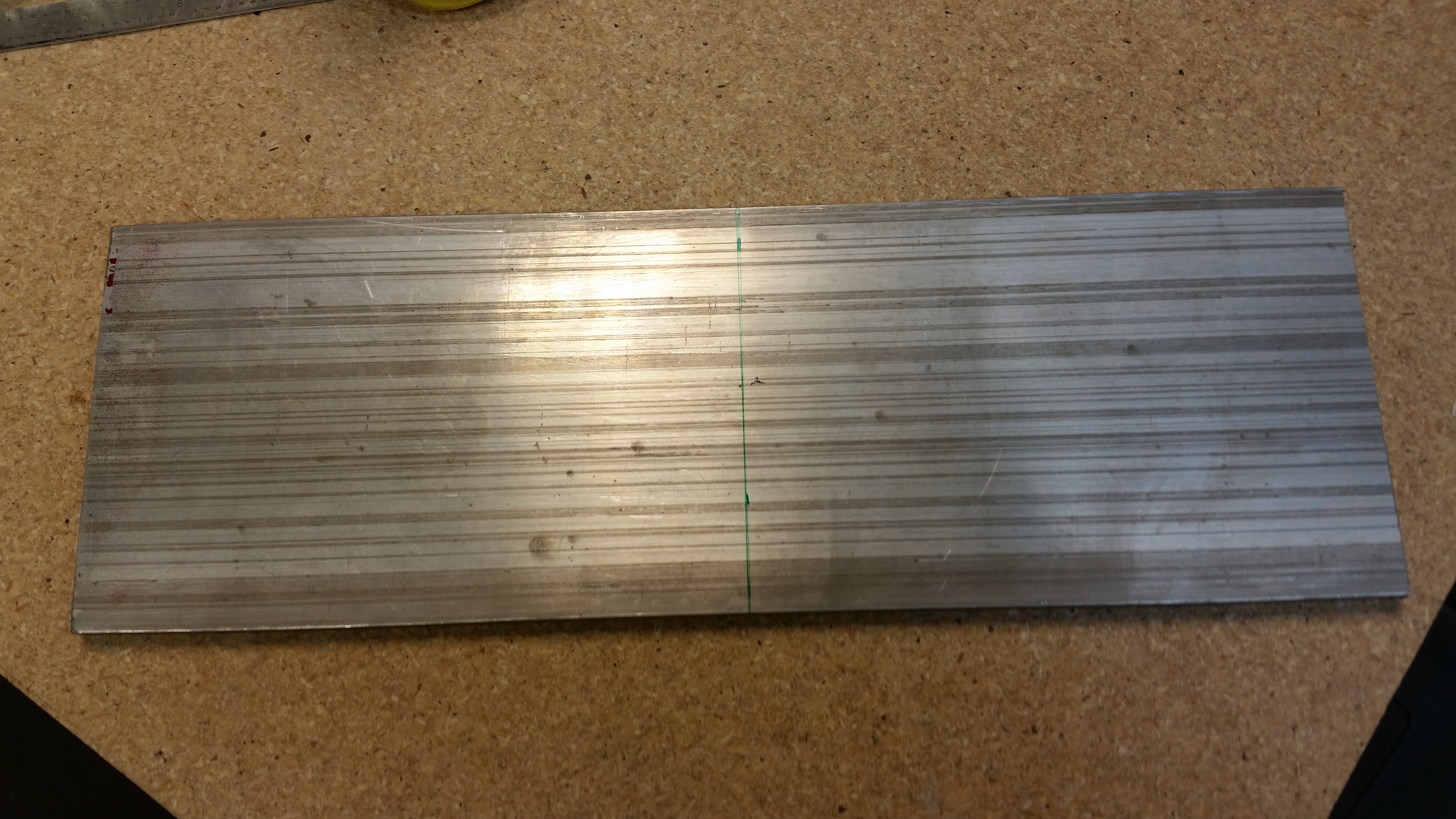
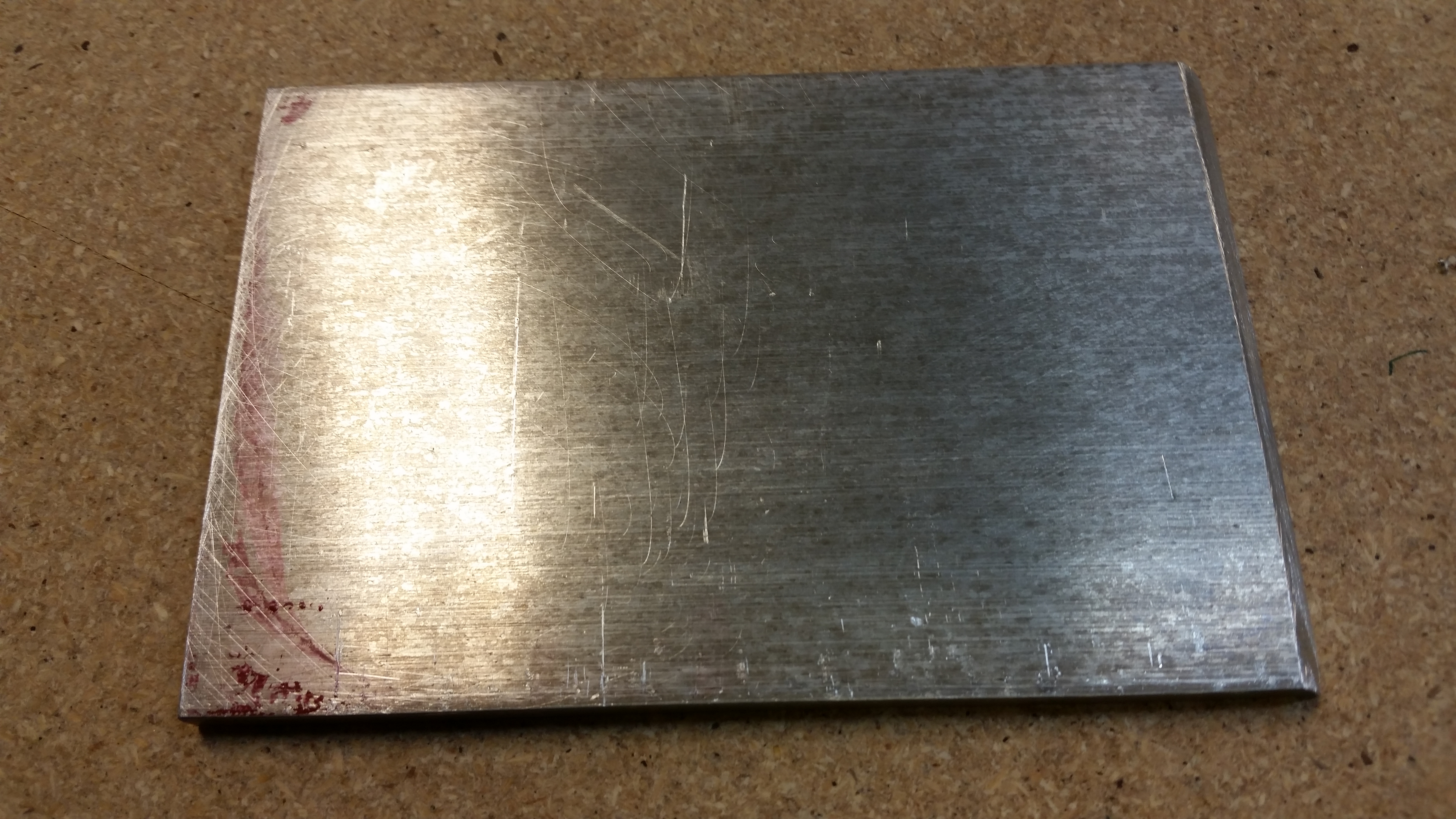
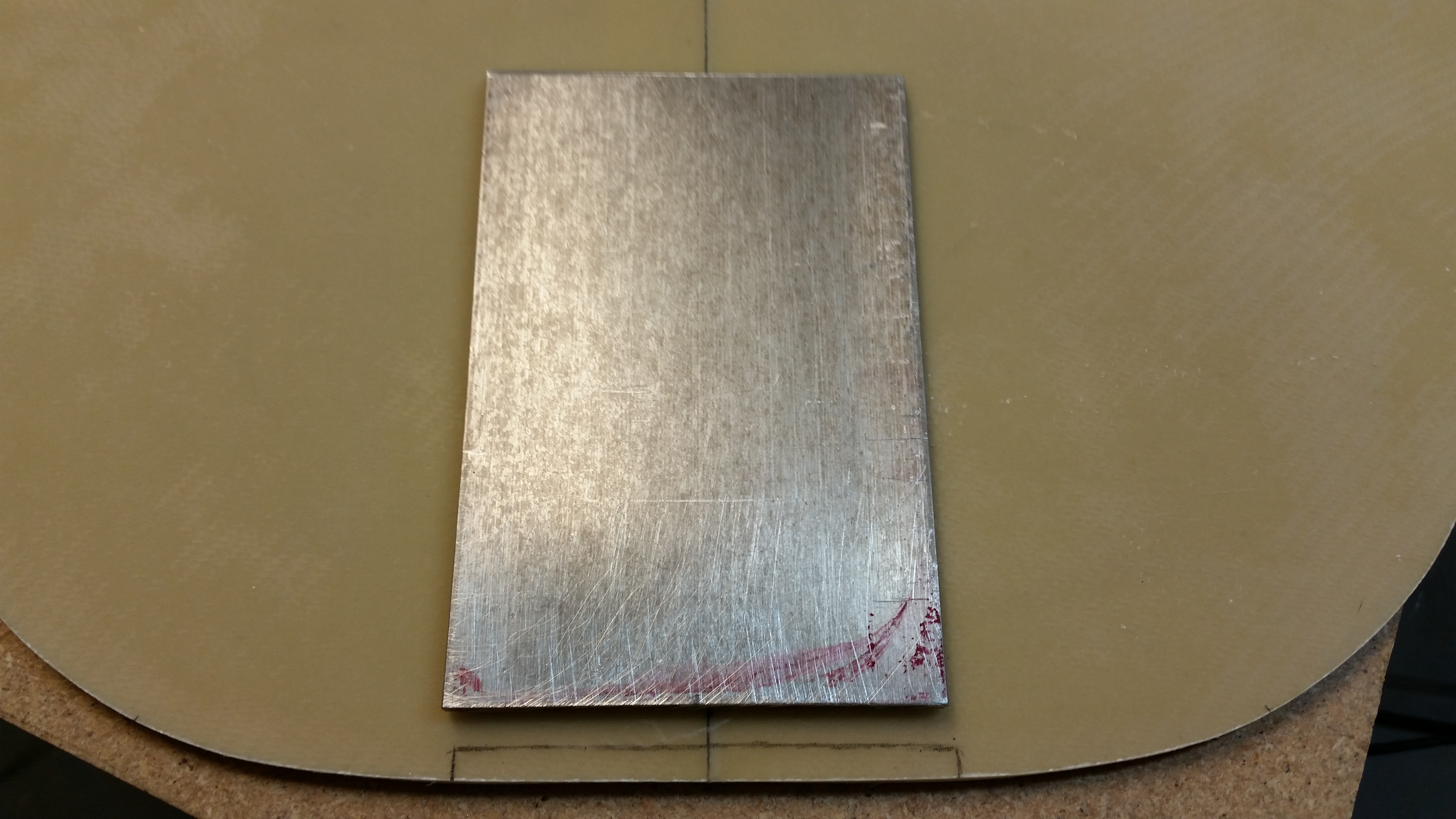
I then started working on the 1/4″ 2024 aluminum skid plate that I’ll be mounting on the lower nose.  I marked a cut line at 6.2″ and then cut it at 45° along this line.

2024 Aluminum Skid Plate

Here’s the raw cut skid plate.

Skid plate cut to length

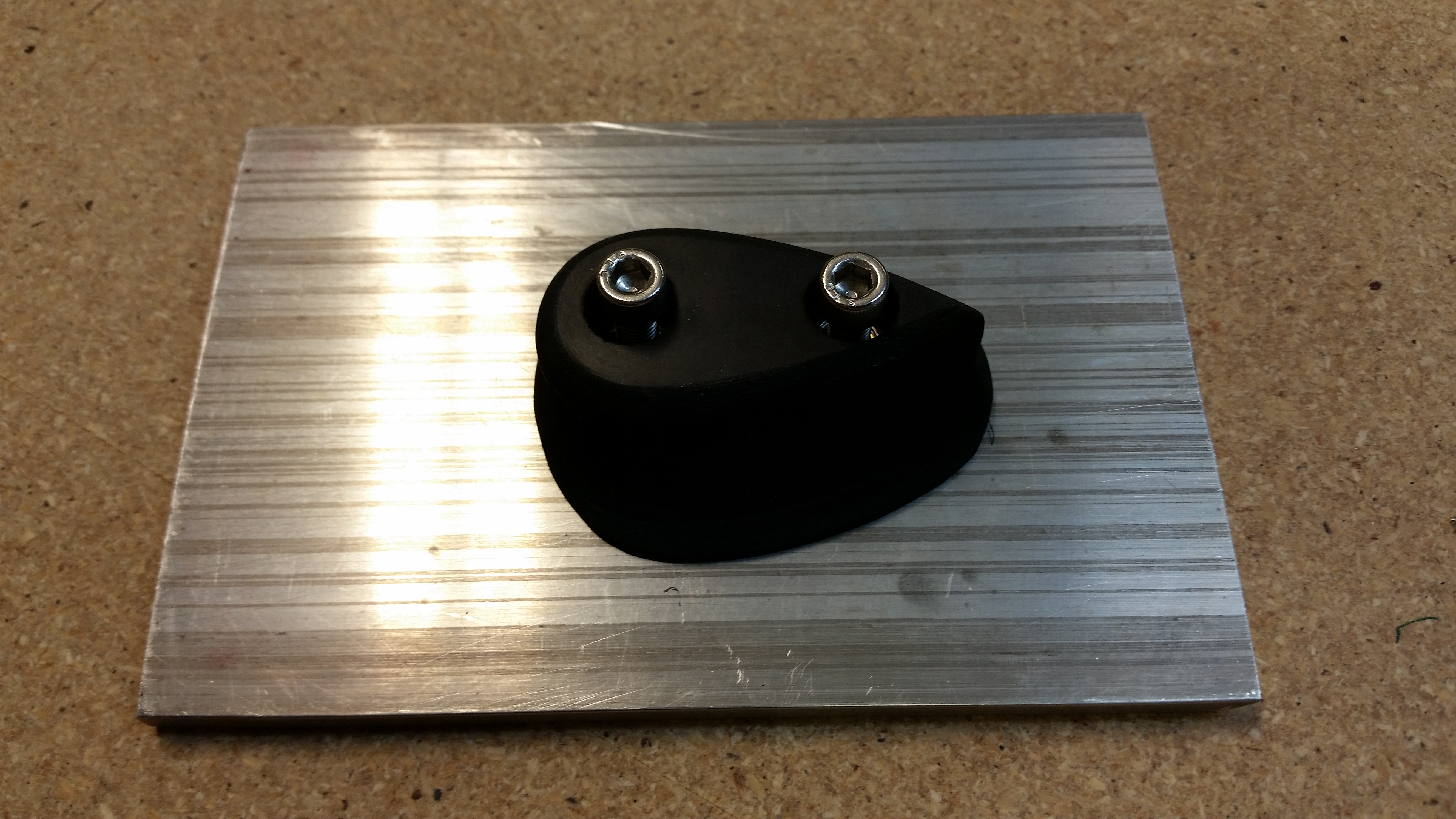
The skid plate will also serve as the mounting plate for the rubber nose bumper that my buddy Marco made for me.

Skid plate & bumper base

I cut out a notch on the bottom of the NG1-3 bulkhead, or “Napster” as I call it, for the skid plate… using the skid plate as the template.

Marking up skid plate cutout

I then tested the fit.  Not bad.

Checking skid plate cutout

With Napster prepped, I then taped up the NG6B and its hardware in prep for installing Napster to the forward NG30 uprights.

NG6 taped up for bulkhead attach

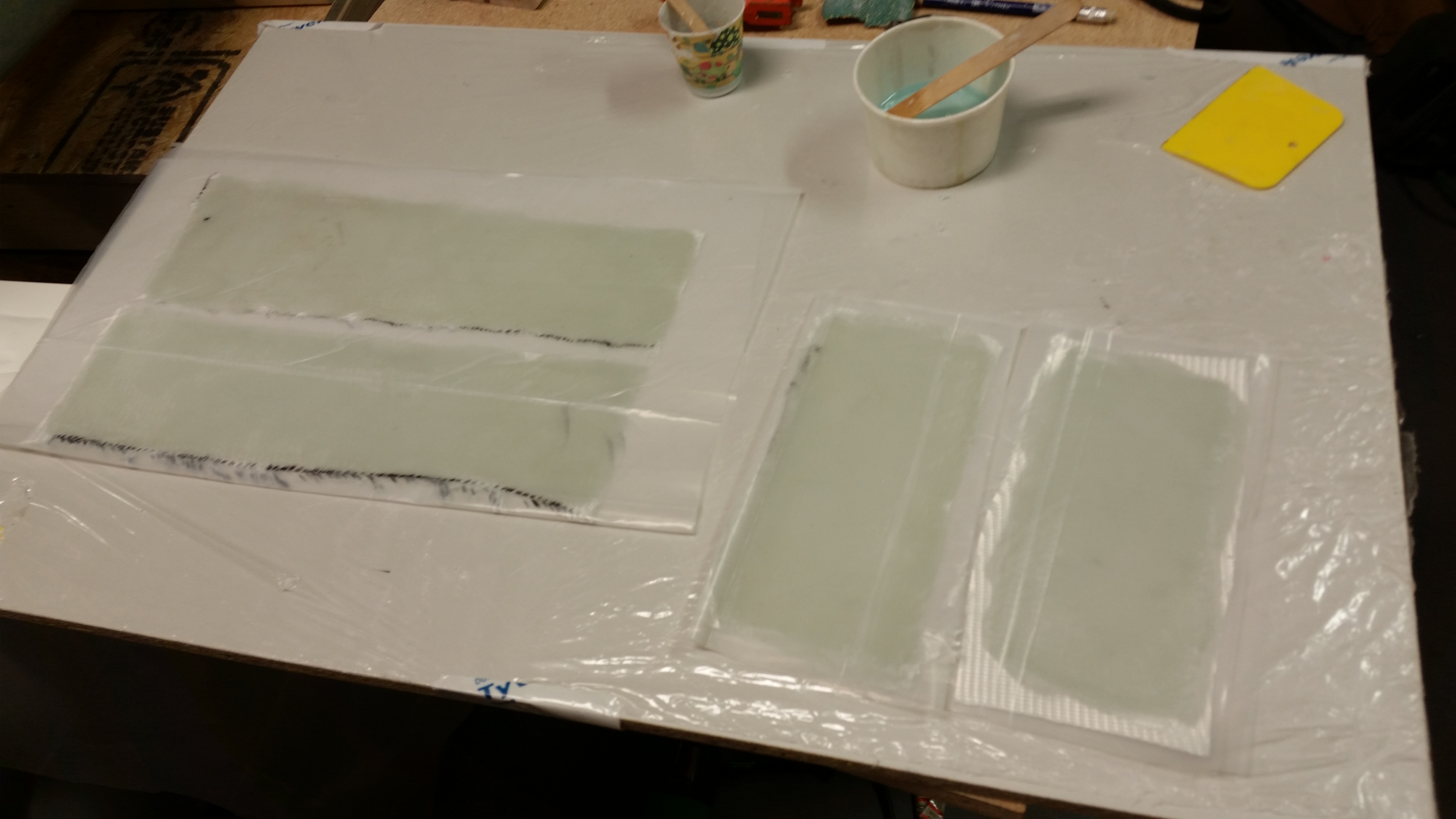
I started prepping the 2-ply BID tape prepreg setups for mounting Napster to the NG30s.

2-ply BID tapes for Napster

I mixed up some epoxy with fast hardener and then made up some flox.  I then applied a bead of flox to front edge of each NG30 upright.

NG30 uprights floxed for bulkhead

Then I cut the BID prepreg setups to size.

Outboard BID tapes for bulkhead

And then laid up the BID tapes on the outboard sides of the NG30 uprights.

After a good night’s cure I’ll remove the NG6B nose gear pivot and lay up the inboard BID tapes to finalize the Napster bulkhead install.

Outboard BID tapes for bulkhead

Tomorrow is Thanksgiving so the build will be light, although I will try to get the inboard BID tapes laid up.


Chapter 13 – Winning by a nose!

Because I now have a nose!

I started out today doing some research on my wiring tools.  I realized that I didn’t have a crimping tool for larger diameter wires under 16 AWG, so I did a little research and ordered one online.

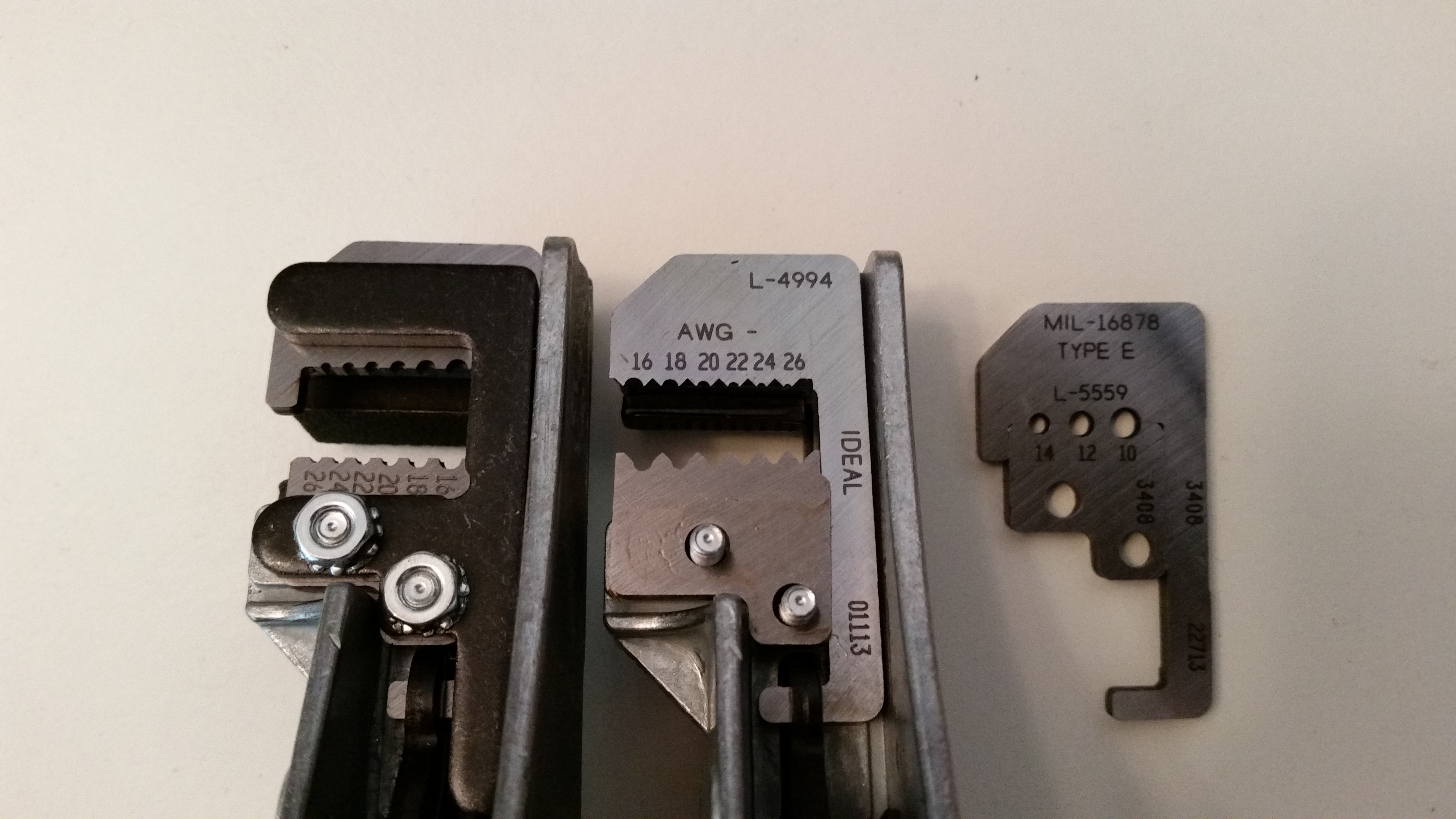
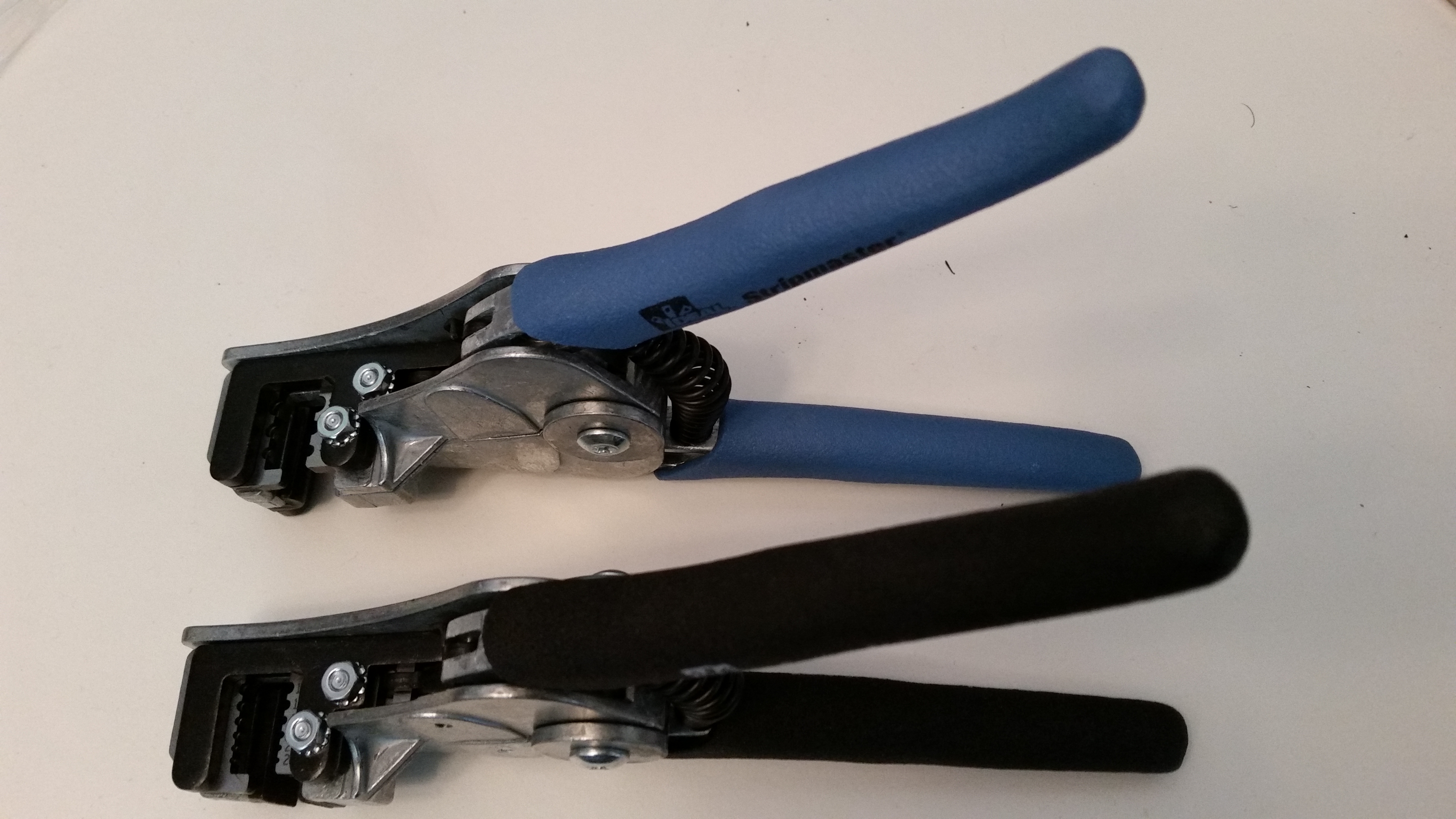
Then, while I was doing an impromptu inventory of my wiring tools, I decided to go ahead and swap out a set of blades to give me a fuller spectrum of MILSPEC wire stripping.  The wire strippers to the left in the pic below are mil spec wire strippers that strip 16-26 AWG wires.  The wire cutters to the right are basically the same strippers that also strip 16-26 AWG, but with standard wire stripping blades for automative purposes, etc., not for aircraft wiring.  While in Qatar I took Nick Ugolini’s advice that he provided on his blog to simply buy a set of aircraft grade mil spec cutting blades (shown to the right below) and install them in a standard, cheaper pair of wire strippers.

Switching wire cutter blades

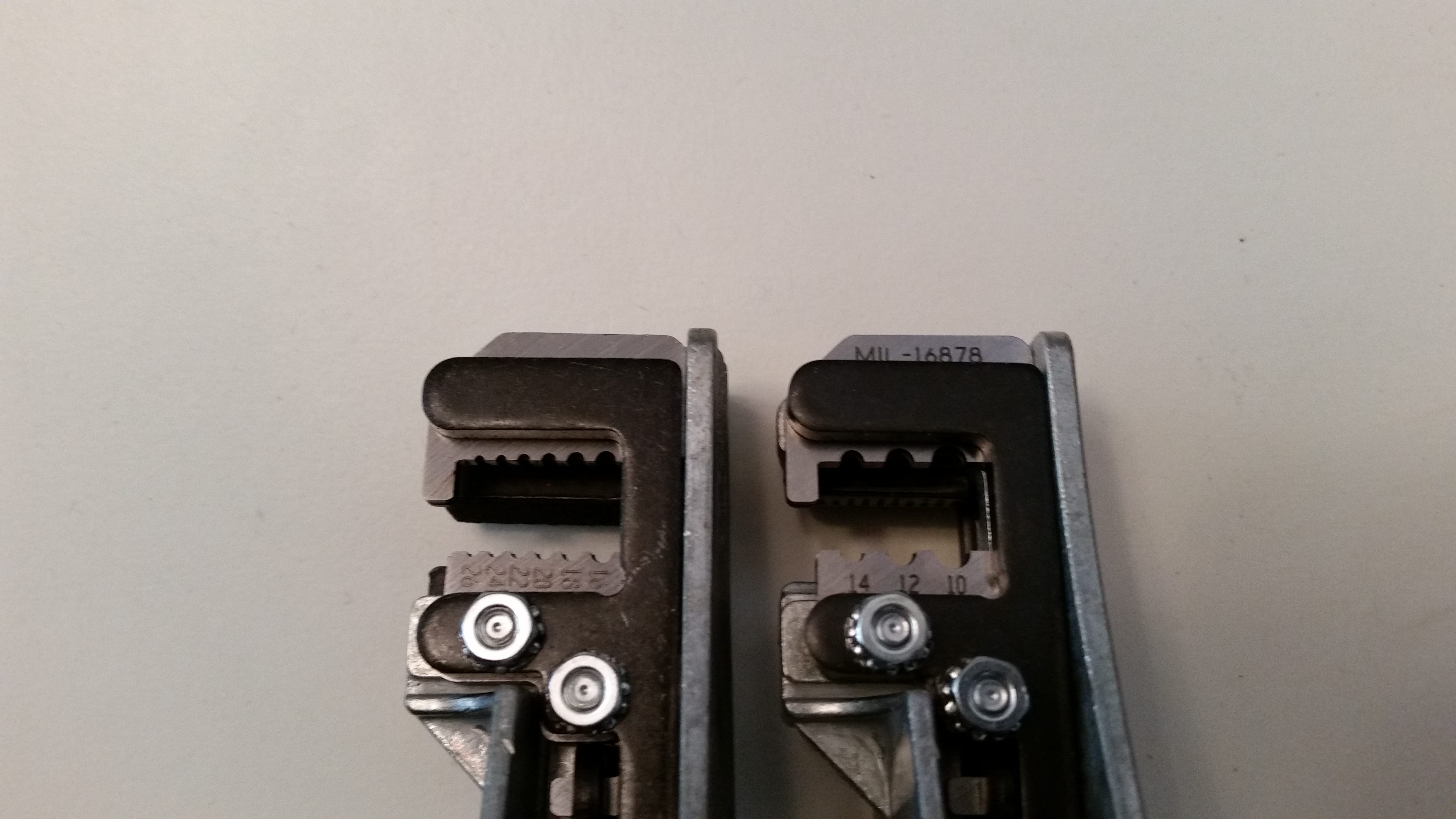
So that’s what I did.  But instead of buying 16-26 AWG mil spec cutting blades, I ordered a set of 10-14 AWG cutting blades to give me the capability to strip wires as large as 10 AWG down to 26 AWG wires.

Wire cutter blades switched

Here’s a couple shots of the wire strippers.

Mil spec & standard wire cuttersMil spec & standard wire cutters

I then started working the install of the NG30 nose gear assembly.  I started by mixing up some MGS epoxy with fast hardener.  I had already prepped the 2-ply BID prepreg setups for both the internal & external BID tapes for attaching the NG30s to the F22 center strut.  I quickly wetted them out and then began mixing up some flox.

Pre-pregged BID tapes

I applied the flox to the aft edges of the NG30s.

Floxed NG30 aft edges

After applying the flox to the NG30s aft edges, I attached them to the front of F22 with the clamp and then marked up the internal 2-ply BID tapes and cut them to length: 13.5″ long x 3.3″ wide.

Interior NG30 BID tapes

I then laid up the NG30 assembly’s internal BID tapes after applying pure epoxy to prep the glass surfaces.

Interior NG30 BID tape layupsInterior NG30 BID tape layupsAfter laying up the internal NG30 BID tapes, I did a final alignment check with the laser. Thankfully it was spot on.

Double checking alignment

Double checking alignment

I then laid up the external BID tapes that wrap around the aft side of the F22 center strut on the first inch and a half of each aft NG30 edge.  Because of the clamp securing the NG30 assembly to the F22 center strut, I could only lay up the top 7″ of the external BID tapes.  I’ll add the bottom external BID tapes later.

Mounting NG30 nose assembly

After I peel plied the external BID tapes, I was in the middle of adding the first of some peel ply strips to the edges of the internal BID tapes when I felt the epoxy cup in my hand getting really warm.  I was able to get a little bit more epoxy on the center peel ply strip but I stopped when the epoxy started getting much, much warmer and was clearly heading towards exotherm.

Since the internal BID tapes will rarely see the light of day, I left them as is and didn’t mix up any more epoxy to add any more peel ply.

Interior NG30 BID tapes

Here’s a shot of the left side external peel plied BID tape.

Exterior NG30 BID tapes

And an aft view of the external BID tapes.

Exterior BID tapes - aft view

I then fired up a heat lamp and took a break for dinner.

Heat lamp for curing

Upon my return from dinner I removed the peel ply from the external BID tapes.

Ext BID tape - peel ply pulledExt BID tape - peel ply pulled

Exterior BID tapes - peel ply pulled

I then razor trimmed the top area of the NG30s.

Interior NG30 BID tapes

I then removed the one piece of internal peel ply, and then the protective tape around the nose gear actuator mount.

Interior BID tapes - glass trimmed

Tomorrow I plan on laying up the bottom external BID tapes.  As the the BID tapes cure, I’ll be working on the elevators to ensure they’re balanced and meet the up/down angle specs on the canard.


Chapters 11 & 13 – Whale gettin’ a nose!

Oh, and the left elevator rebuild is complete!

I finished the left elevator rebuild by laying up the 2-ply UNI strip layup around the outboard elevator weight.

Outboard elevator weight UNI

I then peel plied the layup.

Elevator weight 2-ply UNI layup

I then turned my sights on the nose area, or F22 as it is right now.  To prep the brake line secure and protect layup on each side, I first slid another 6″ of Nylaflow to jut up against the end of they current Nylaflow.  A good portion of this new Nylaflow will get buried under Micro & glass.

Adding 6" of Nylaflow to brake lines

With the left over epoxy from the elevator weight glassing, I whipped up some thick micro and micro’d in the urethane foam piece with a good slathering.

Introducing . . . micro gunk!

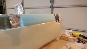
I then laid up first the left side, and then the right side with 1-ply BID over the foam ramps. The popsicle sticks in the pics are holding the glass down that surrounds the upper brake line.  I then applied peel ply to each layup.

Frankenstein's layup . . . ha!Right side brake line protect layup

Here’s a shot of the completed left elevator . . .  hoo-ah!

Left elevator rebuild finished!

And here’s the trimmed outboard elevator weight glass.

Trimmed outboard elevator weight

I turned my sights back onto the F22 center strut.  I sanded the forward face and then hit each back corner with the sanding  black to radius it a bit for the glass tapes that will hold the nose gear frame (NG30s) to the center strut.

F22 middle strut corners radiused

Here are the finished layups for the right & left side brake line secure, protect & route.

Cured right side brake line protectCured left side brake line protect

Here’s a shot of the new layups from the front.  Notice how the interior area forward of the instrument panel is clean & sanded.  I spent a good hour getting this area sanded and in shape.

Brake line protect layups from front

I then grabbed my trusty string and checked the CL alignment of the bulkheads.

Stringing fuselage CL

I also removed the nose gear actuator from the NG30 frame in prep for glassing the NG30s to the F22 center strut, etc.  Notice that I taped up the mounting brackets & hardware.

NG30 innards protected

Also checked the left-right level of the fuselage across the longerons.  Looks PDG!

Level fuselage L-R

I then clamped up the NG30 nose assembly to F22 on the front of the fuselage to test out the fit & finish of the nose gear frame assembly.  Now, this was just a dress rehearsal, trial run, etc. so I haven’t floxed or taped it on yet.

Whale's gettin' a nose

Here’s a little bit closer shot.  Amazing that although I built the NG30s back in 2013, this is the first time they’ve been mocked up on the nose.

The nose cometh!

To really ensure everything is on the straight and narrow, I pulled out my (also) trusty laser level to shoot some laser lines.  It took me about 5 minutes to get the laser set up and leveled itself.

NG30 laser sighting CL

I then fired a line at the CL of the fuselage and NG30 nose gear assembly.  The laser line was off a very faint tad here & there, but in the end it all lined up, nice & centered!

NG30 laser sighting CL

Tomorrow, I plan on floxing and glassing the NG30 nose gear assembly onto the front of the plane.  I’ll also remount the elevators and test out their range of motion, balance, etc. Finally, if I get time, I’ll be getting back to finishing the underside of the canard.


Chapter 11 – Bits ‘n pieces

I didn’t get a whole lot done today since I relaxed a bit and watched some football, and also ran a few errands.

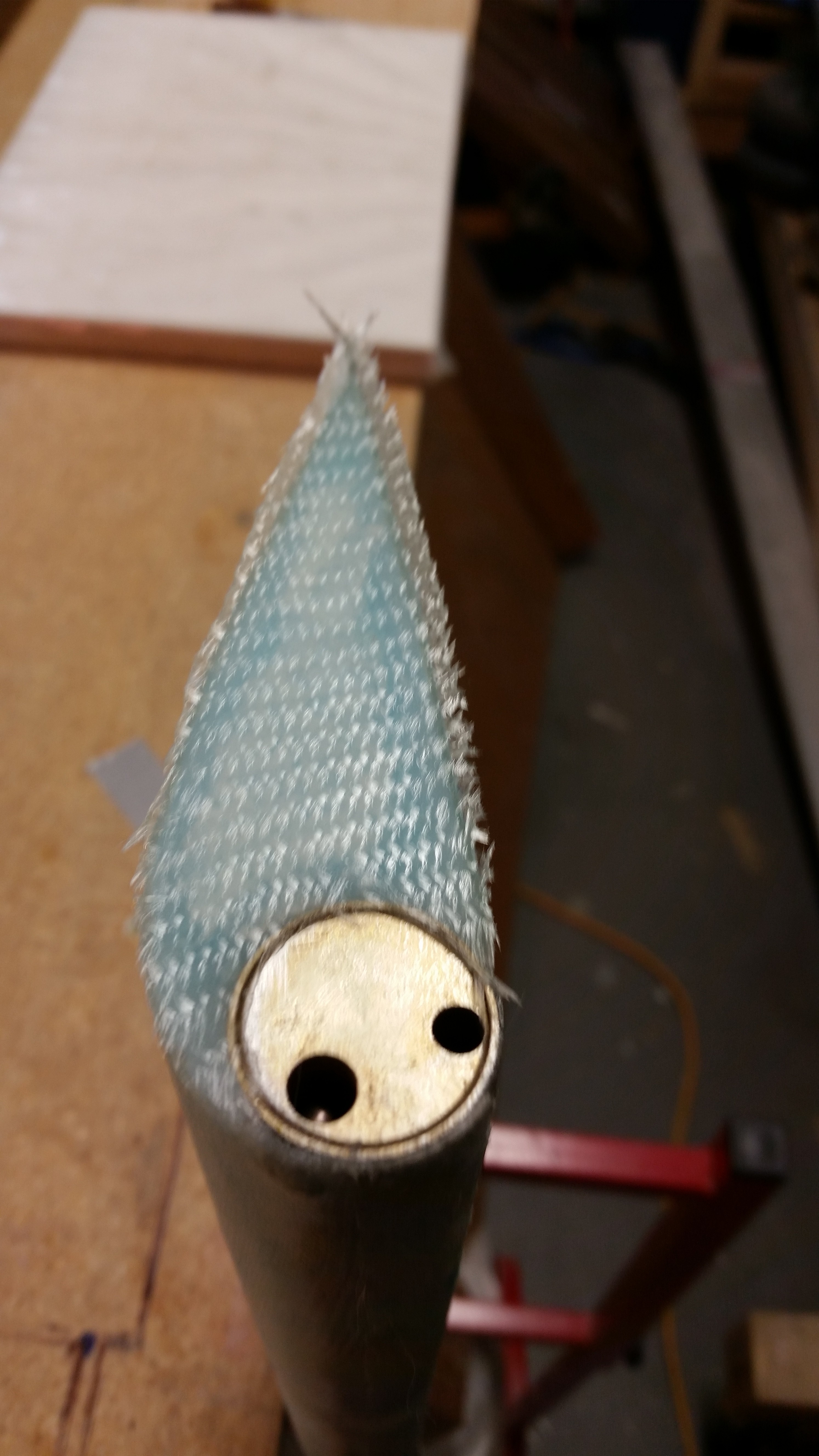
I did get a little bit of work accomplished today though.  I started out by trimming the foam around the inside edges of the glass skin on the outboard end of the elevator.  This foam removal is to allow for flox to be applied to replace the foam in the areas around the perimeter and thus create a “flox corner” for strength.

Foam cut for flox corners

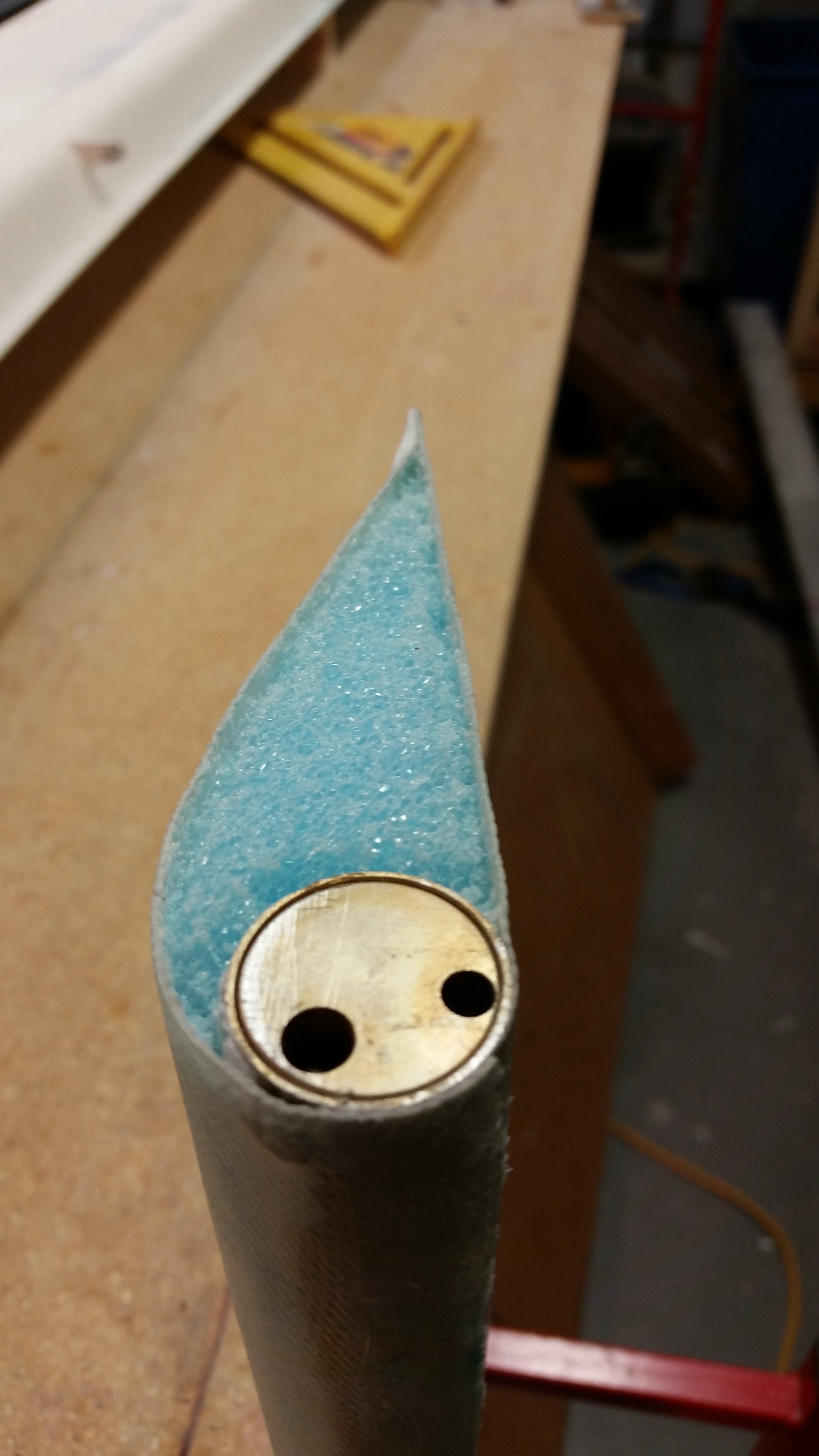
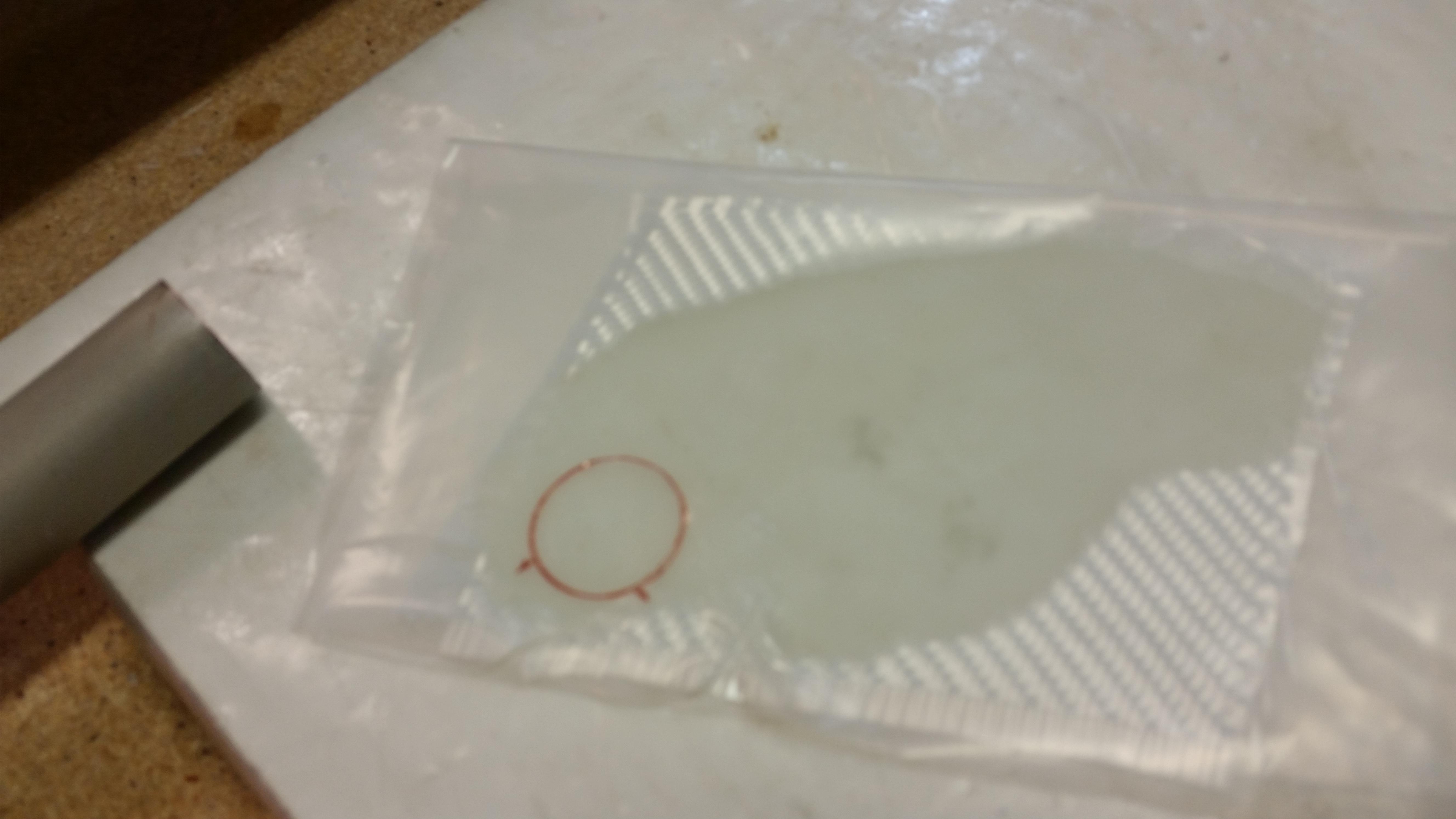
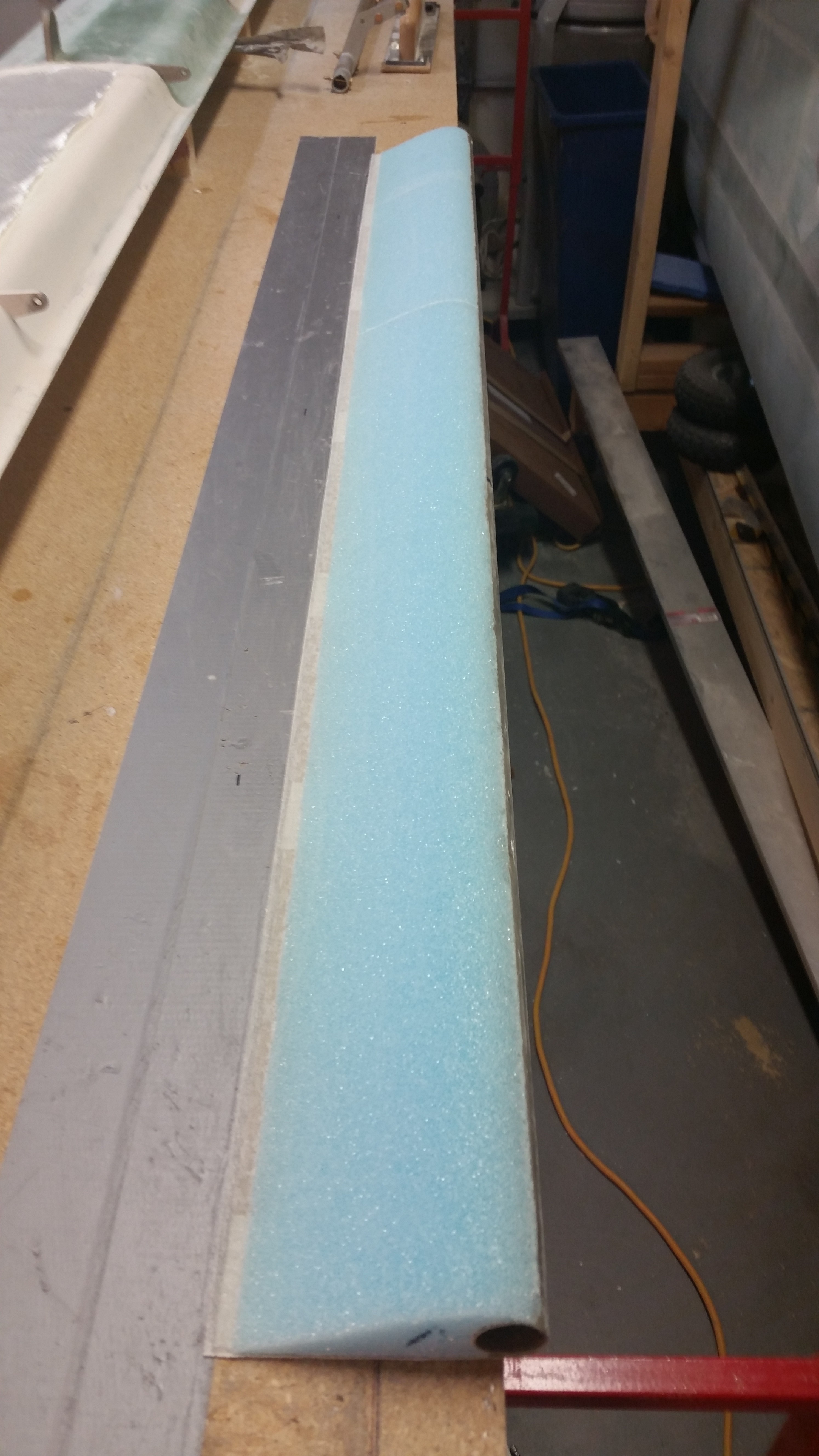
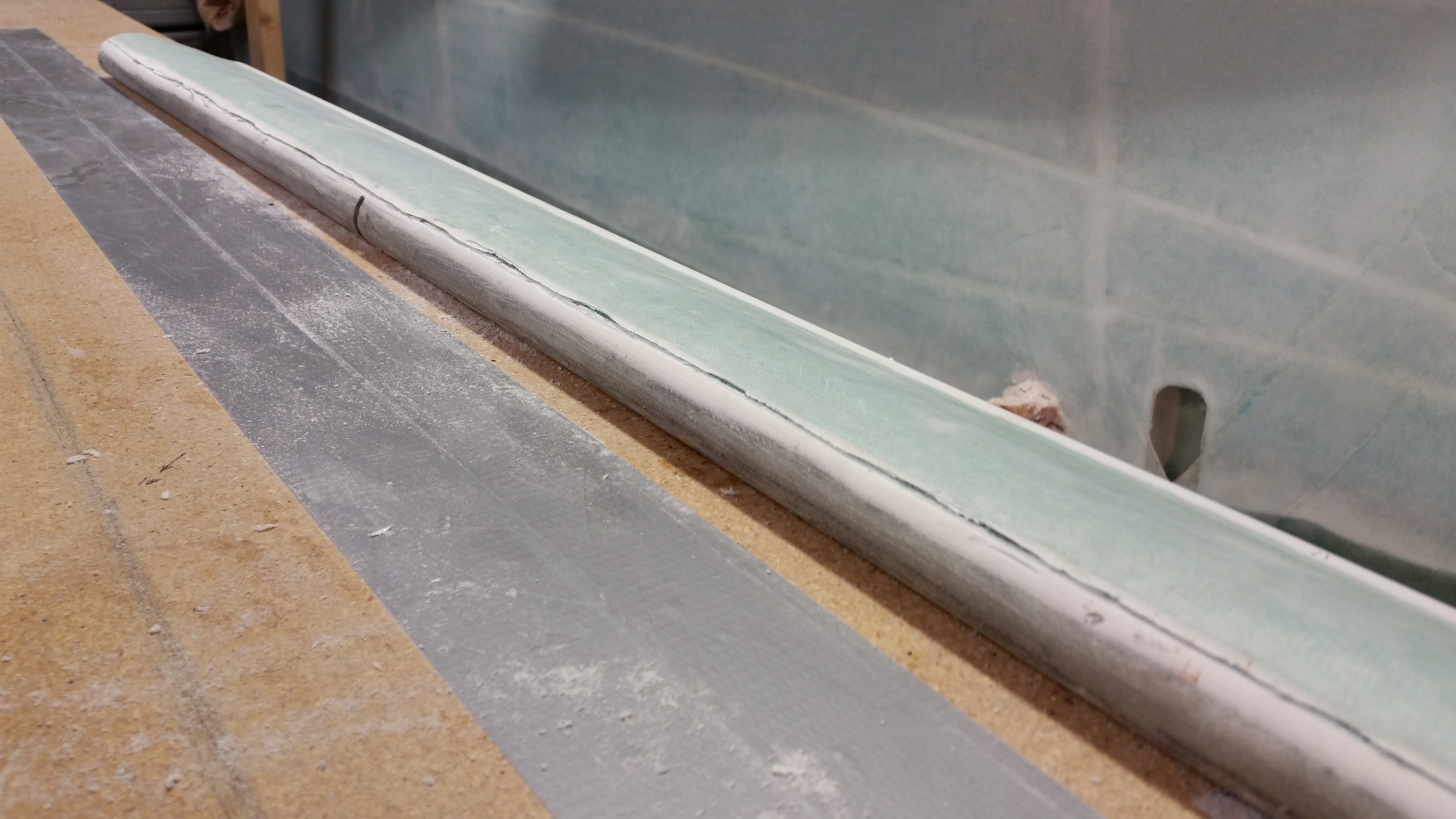
Unlike the other side, where I taped up the NC6 and then worked a fair amount to get the cured glass off of it, this time I simply cut the glass out ahead of time using a 1″ round tube as a template on a pre-pregged ply of BID.

Prepreg with 1" tube marked

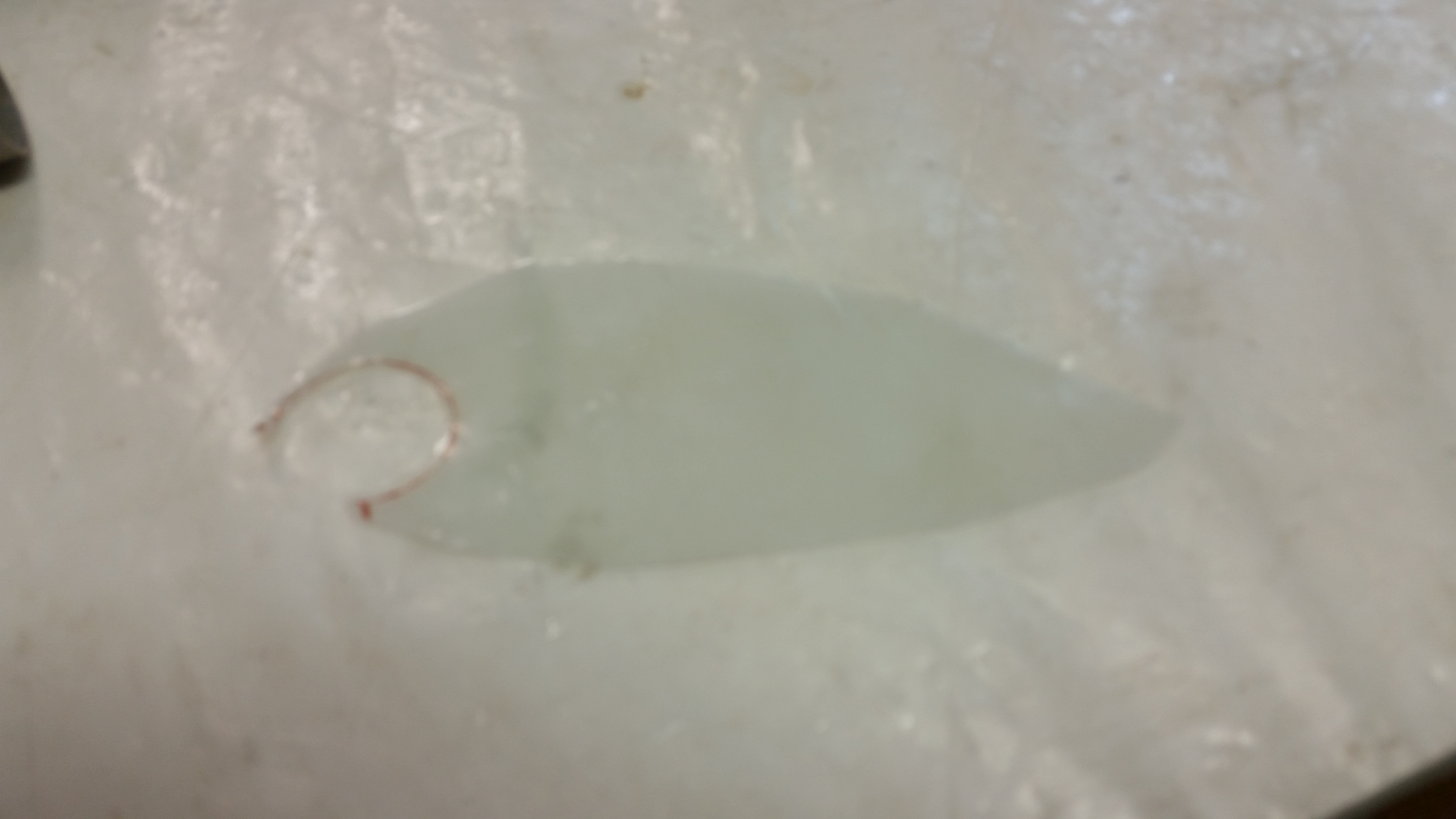
Here’s the prepreg after I cut out the 1″ circle.

Prepreg with tube area cut out

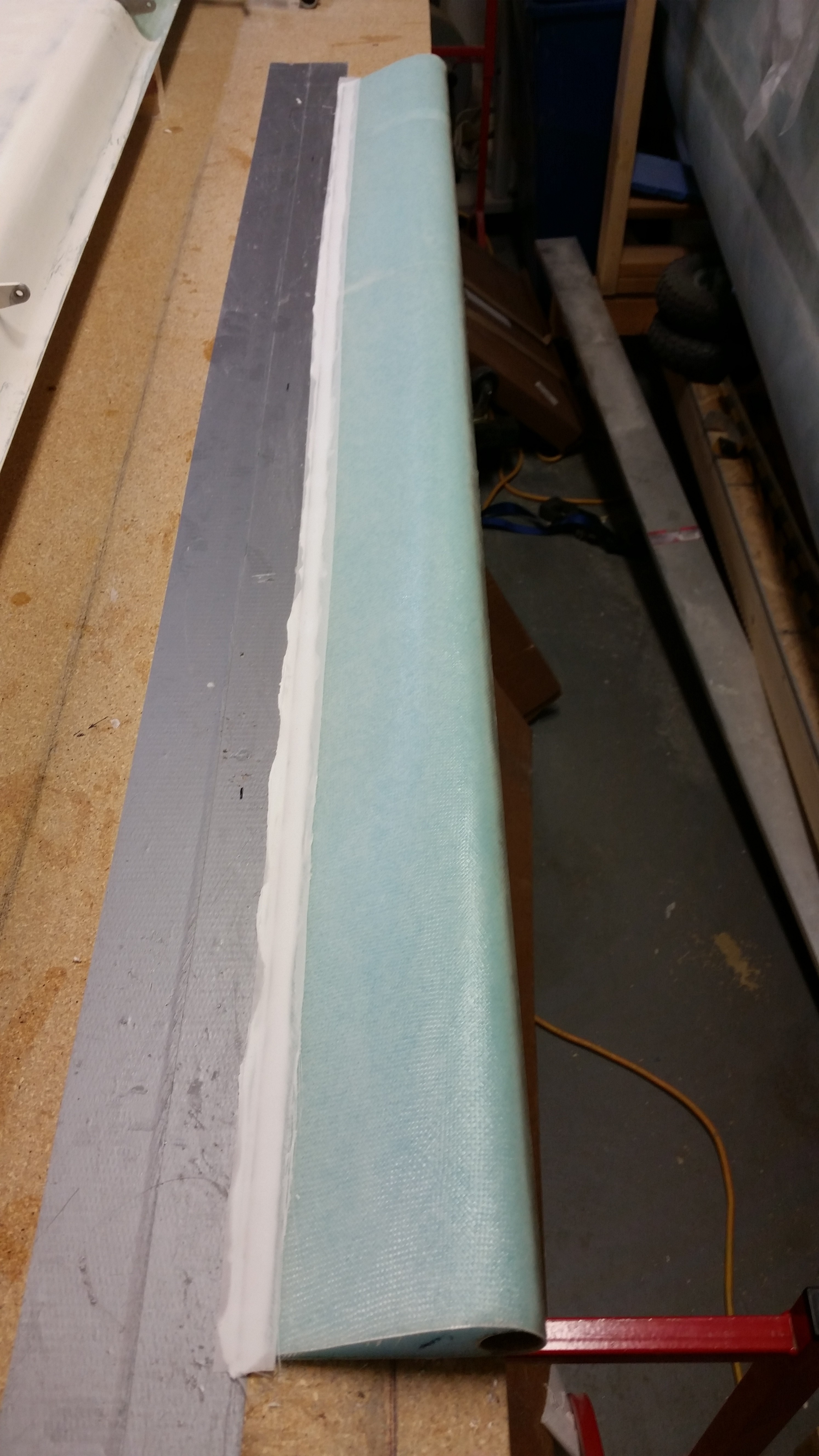
And here’s the layup with the top piece of prepreg plastic still in place.

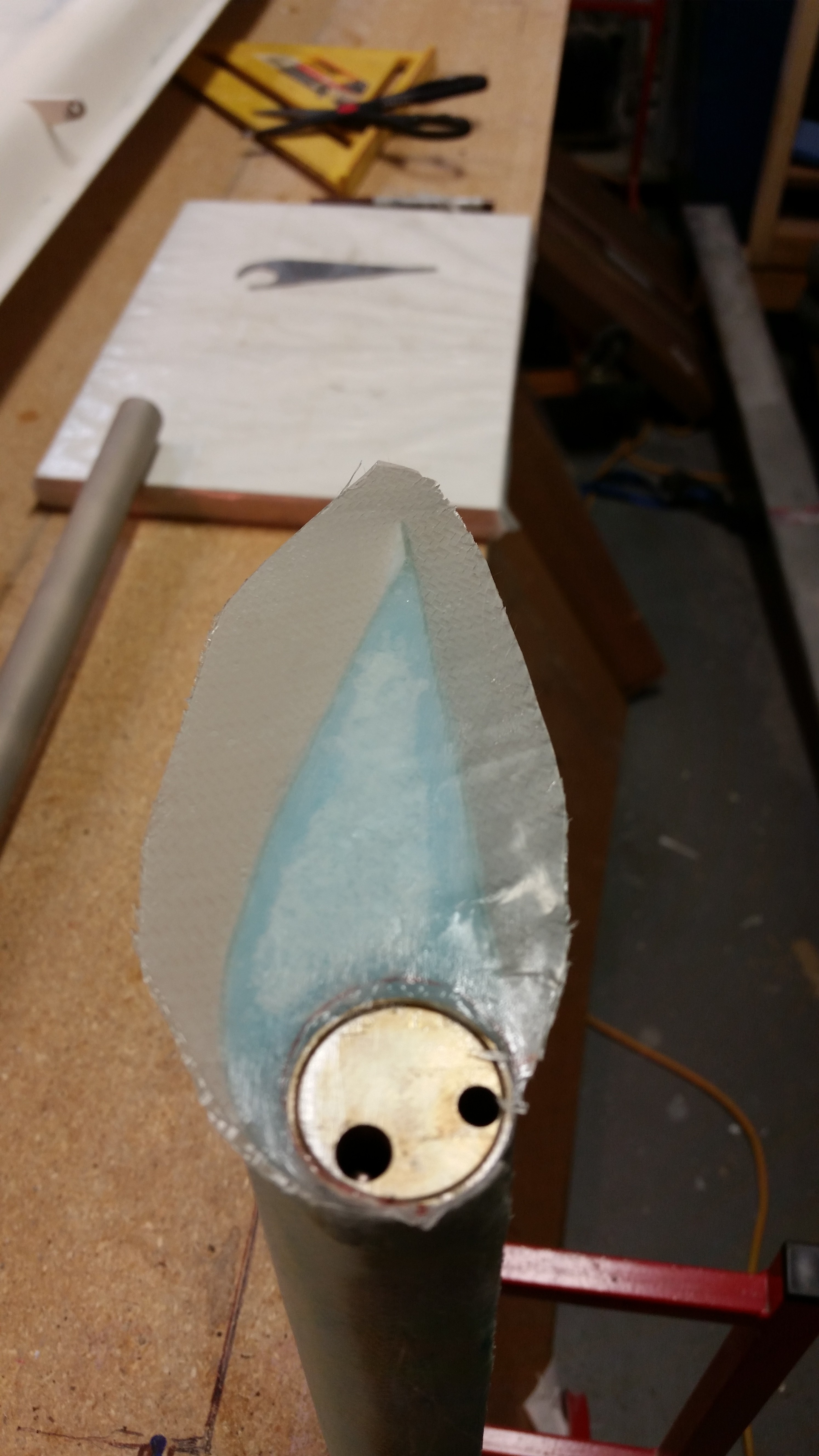
End cap prepregged BID layup

Here’s the layup set to cure.

Outboard end covered 1-Ply BID

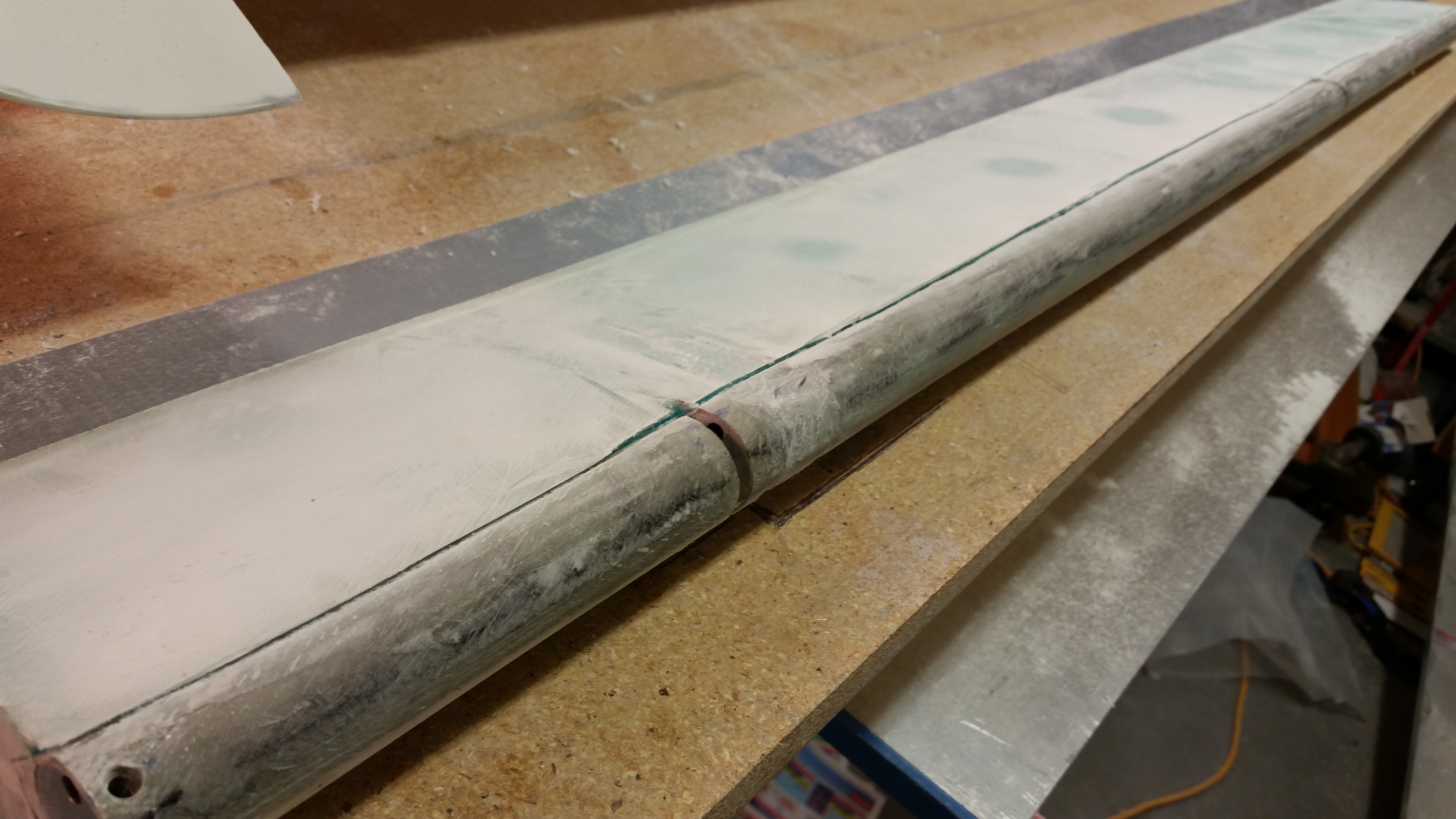
Quite a few hours later I returned and razor edged the elevator end layup.  Since it was pretty much cured, I sanded the corners of the layup to smooth everything out.

I don’t have a pic of it, but I did spend a little time removing all the protective tape from the various holes in the elevator  I cut the glass covering the hinge tab slots, and then drilled out the holes on each end: one for the set screw and the other for the torque offset bolt, respectively.  I also sanded the LE a bit to get everything smooth & even.

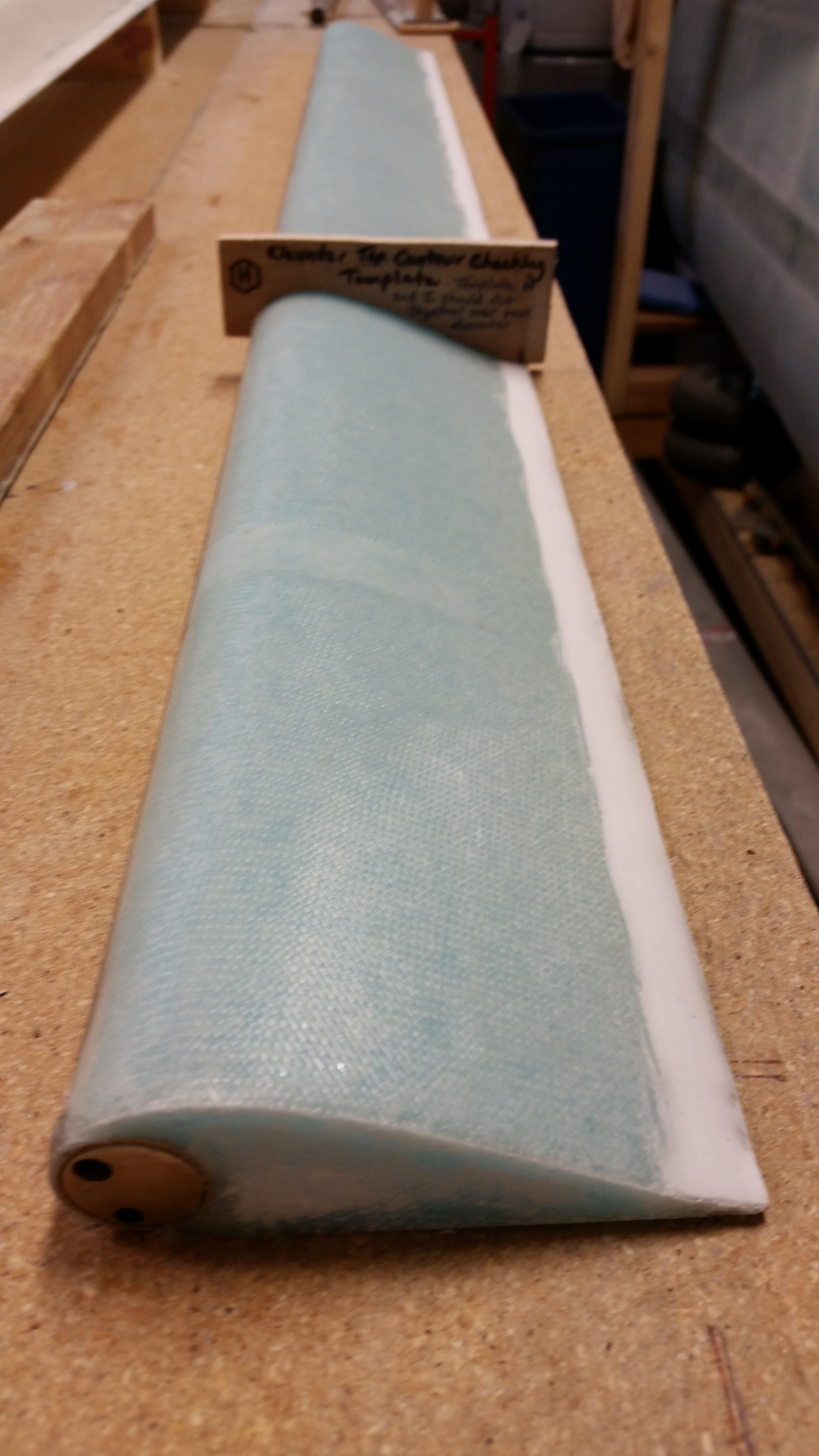
Here’s a shot of the end of the elevator, and the contour template in place as well.

Outboard end glass, trimmed, sanded

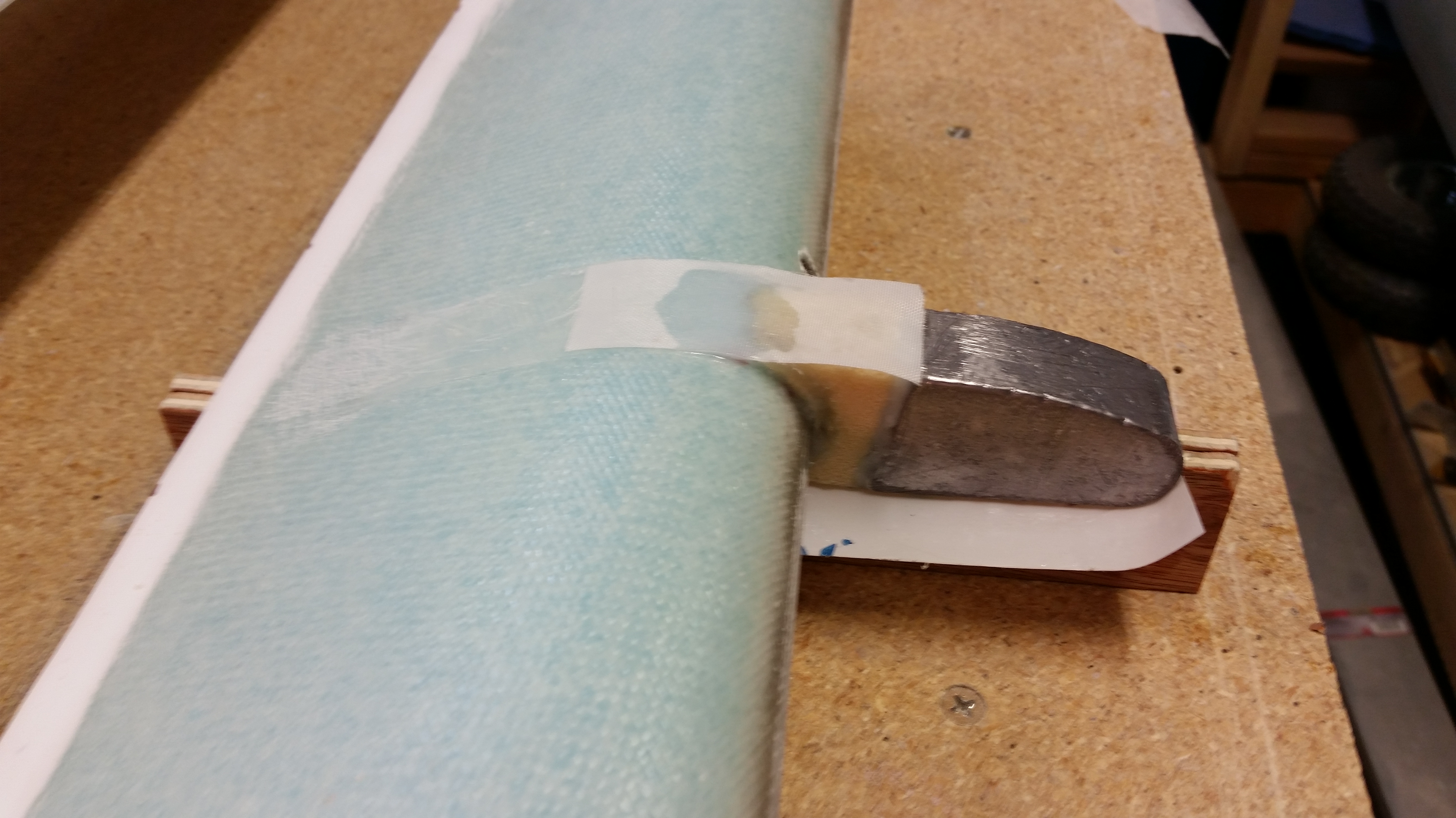
My last act of the evening (besides some research) was to re-attach the outboard elevator weight with flox.  On this side the foam wasn’t too bad off, so I reused it.  I did add a small crescent moon shaped foam spacer to help fill in a gap where it met the LE.  I mounted it to the elevator with flox made with fast hardener.

Re-attaching outboard weight

Tomorrow I should get around to covering the outboard weight with 2 plies of UNI.  I’ll also be working to sand down the TE on both elevators to dial in the correct width.


Chapter 11 – Coming to an end!

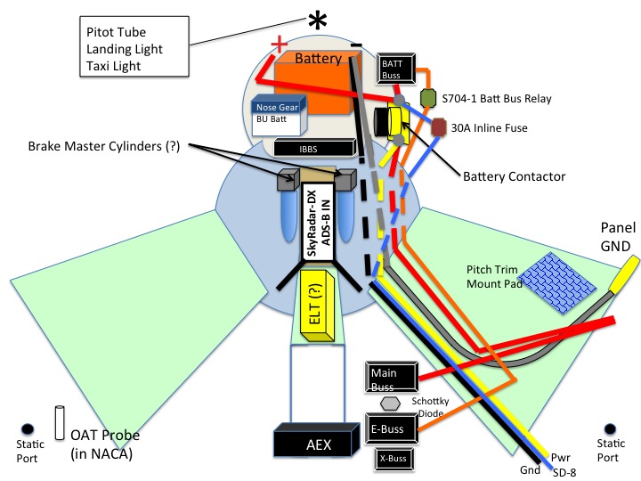
I mentioned that I had updated my electrical component placement plan for the nose.  I finished the final mods this morning and figured I would post it for you all to see.

Updated Nose Electrical Gear

I installed the 5/16″ bolts that I bought last night at Home Depot into the forward & aft fuselage cradles.

Fuselage tie-down strap

Here’s a shot of the front fuselage cradle bolted in place.

Saddle mount bolts

After using the Dremel tool on the elevator TE to clean off the foam & micro to ensure a good glass-to-glass bond, I applied foil tape to the bottom of the elevator and instead of Bondo I used 5-min glue to secure the elevator to the table.

5-min glue application on foil tape

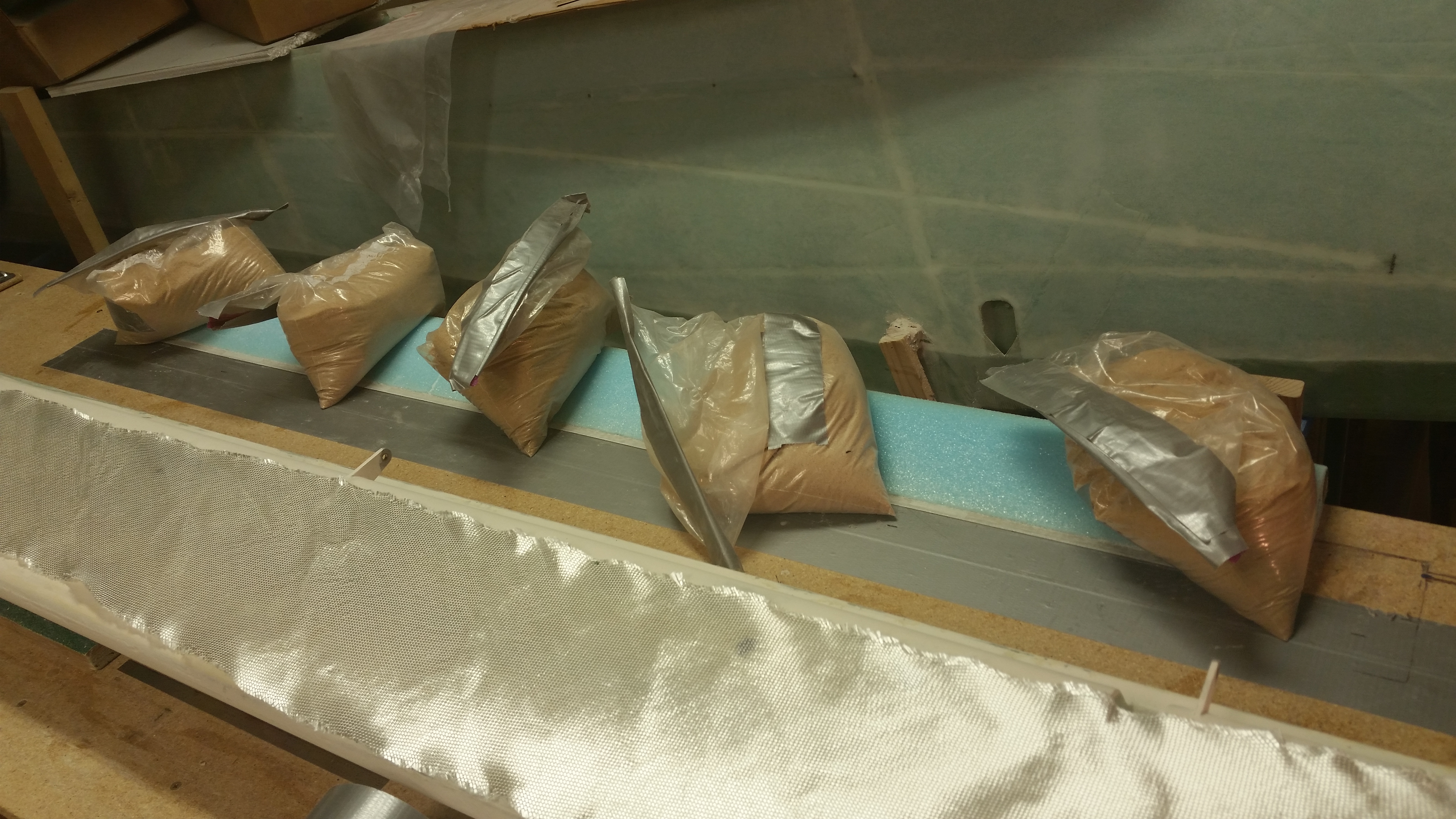
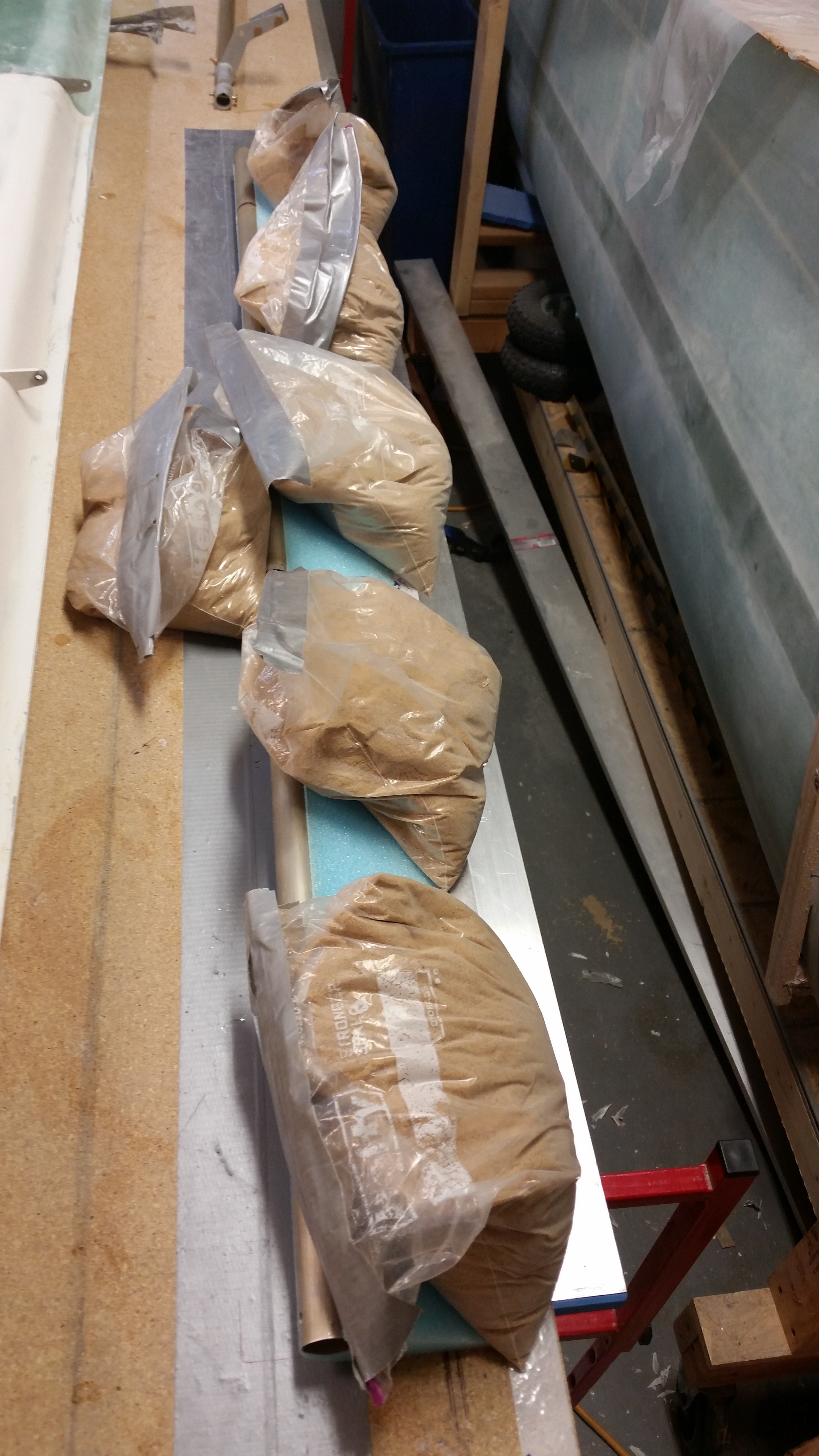
I weighed down the elevator as the 5-minute glue cured.

Elevator 5-min glued to workbench

I re-vacuumed the top of the elevator after removing the sandbags and then whipped up some micro and applied it.

Elevator ready for glass

Elevator micro'd

Here’s a shot after I completed the 2-ply UNI layup.

Top of left elevator glassed

A close up shot to show how dry the layup is … can you tell?

Pretty dry layup!

After a couple of hours I applied dry micro to the TE and then covered the micro with a 1″ wide strip of peel ply.

Razor trimmed & TE micro'd

Tomorrow I plan on getting the outboard end glassed and also the outboard weight reattached.  After that, I’ll just need to clean out the hinge slots and holes and the left elevator will be complete!


Oh, Chapter 11 end…where art thou?!

Today was still all about finishing the left elevator rebuild . . . (big sigh!)

I was pleased to find no nasty surprises when I took the sandbags off the foam elevator cores.  So far my evil plan is working to get the elevators to align.

Foam core micro'd to elevator tube

I started off by taping up all the openings on the elevator tube to keep the epoxy out of all the important orifices.

Taping up holes to keep epoxy gremlins out!

I then covered the top of the elevator foam core with patches of foil tape, hit each one with a drop of 5-min glue, and then mounted the elevator upside down on the work bench.  I weighed down the elevator with sandbags, favoring the LE side.

Mounted upside down with 5-min glue

Although tough to see in this pic, I remembered to slightly sand the area where the outboard weight UNI will reside on the bottom face of the elevator.

Fuzzy shot of outboard weight depression

Since I had my Friday afternoon online work meeting I didn’t want to start the layup of the bottom elevator UNI knowing that it would take too long for me to finish.  So instead, I knocked another item off my list by cleaning up some epoxy goo on the face of the F22.

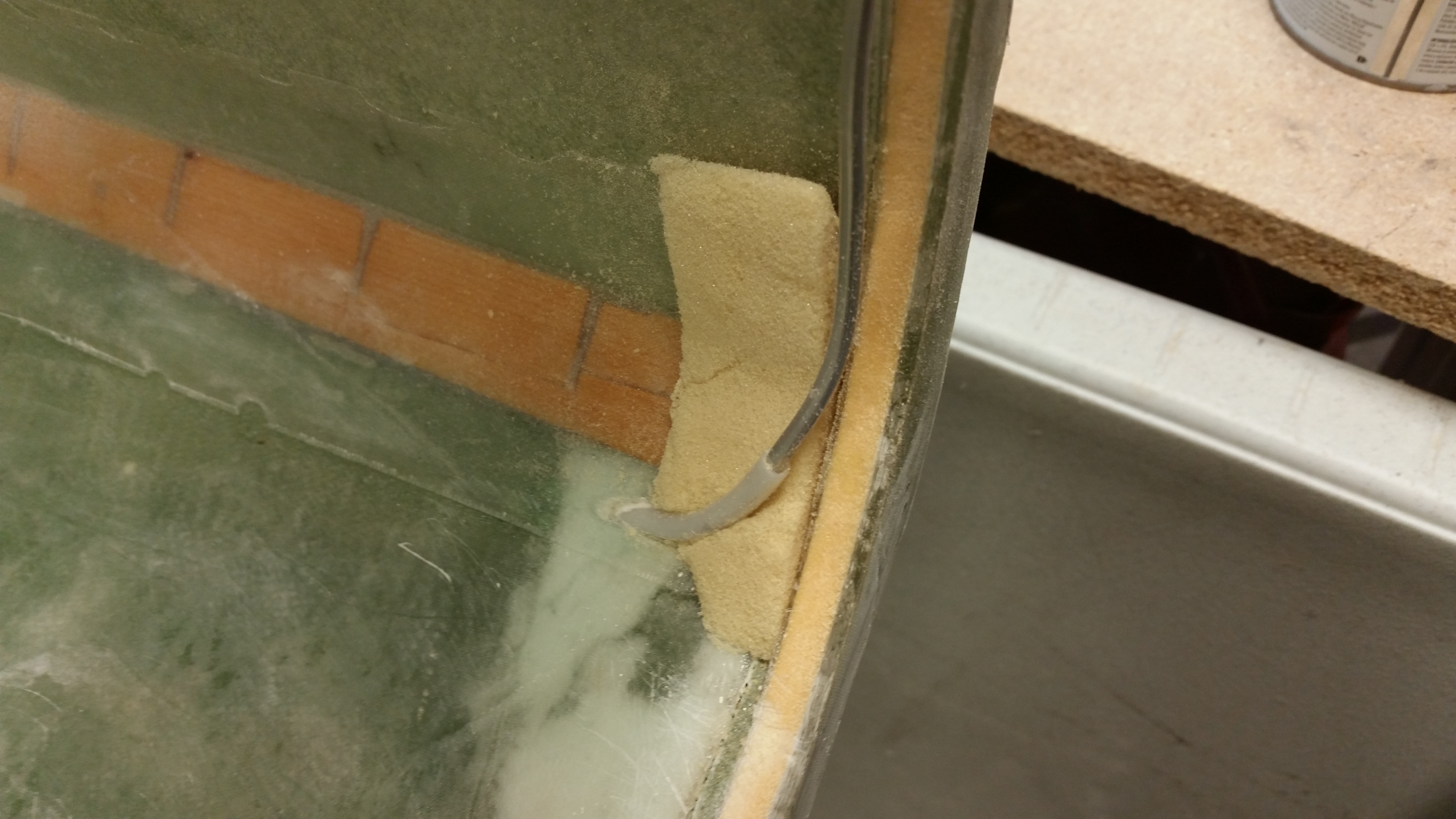
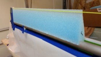
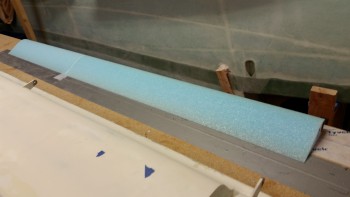
Then, while I was standing there looking over the F22 area, I realized that my internal brake lines were kinda hanging out into space.  I wanted to secure them in place & protect them, so I grabbed a piece of nasty urethane foam and hacked it up and shaped a reasonable gap filler ramp on each side to slide in between the brake line, the fuselage floor/wall and F22, on each side of course.  I’ll install these with a lot of messy micro and 1 ply of BID.

Foam support for left brake line

Foam support for right brake line

After my work call, I then laid up the 2-ply UNI elevator bottom skin.

The first pic is a fuzzy shot of the elevator bottom layup when it hit its “green” stage (trust me, it looked FAB-U-LOUS! haha!).  I then razor trimmed the elevator.

Fuzzy pic of green cured elevator bottom

Razor trimmed elevator bottom skin

While I was waiting for the elevator to cure I (finally!) went ahead and finished wiring up the nose gear actuator to test it out.  You can see the test in the video below:

Then, to let the glass cure even longer, I took the opportunity to run down to Home Depot to grab some 5/16″ bolts to attach the fuselage saddles to the fuselage dolly cross struts.  While out, I called a good buddy of mine and ended up on with him for over an hour.  This came into play since later in the evening I simply ran out of time… to make noise!

After I got back home, with the elevator skin cured more, I pulled the peel ply off the outboard weight mount area.

Peel plied pulled - weight depression

I then popped the elevator off the work bench.  The pic below shows why I love using the foil tape so much. It holds incredibly well, but all but one of the pieces of foil tape stayed on the bench.  Again, the top of the elevator foam core is clean … without any divots!

Elevator pulled up from table

I trimmed the foam off the elevator TE, but I couldn’t finish the job because it was late and I didn’t want to make a lot of noise with the Dremel Tool.  So instead I prepped the entire elevator to skin the top of it first thing tomorrow morning.

Elevator TE

I then sanded the glass edge on the LE to provide a smooth transition for the top skin.

Sanded LE glass

I also sanded the depression for the outboard elevator weight on the top foam core.

Depression for outboard weight

With all the prep actions completed for laying up the top elevator skin except for clearing the TE glass of all the foam & micro gunk, I turned out the lights and called it a night.

Prepped for tomorrow

Again, tomorrow first thing I will layup the 2-ply UNI top elevator skin.  I have a lot of non-build work to do this weekend so my time to work on the plane will be limited.  That being the case, I still want to get this elevator completed.


ABB – Always Be Building!!!

Not that I am… but I like the concept!

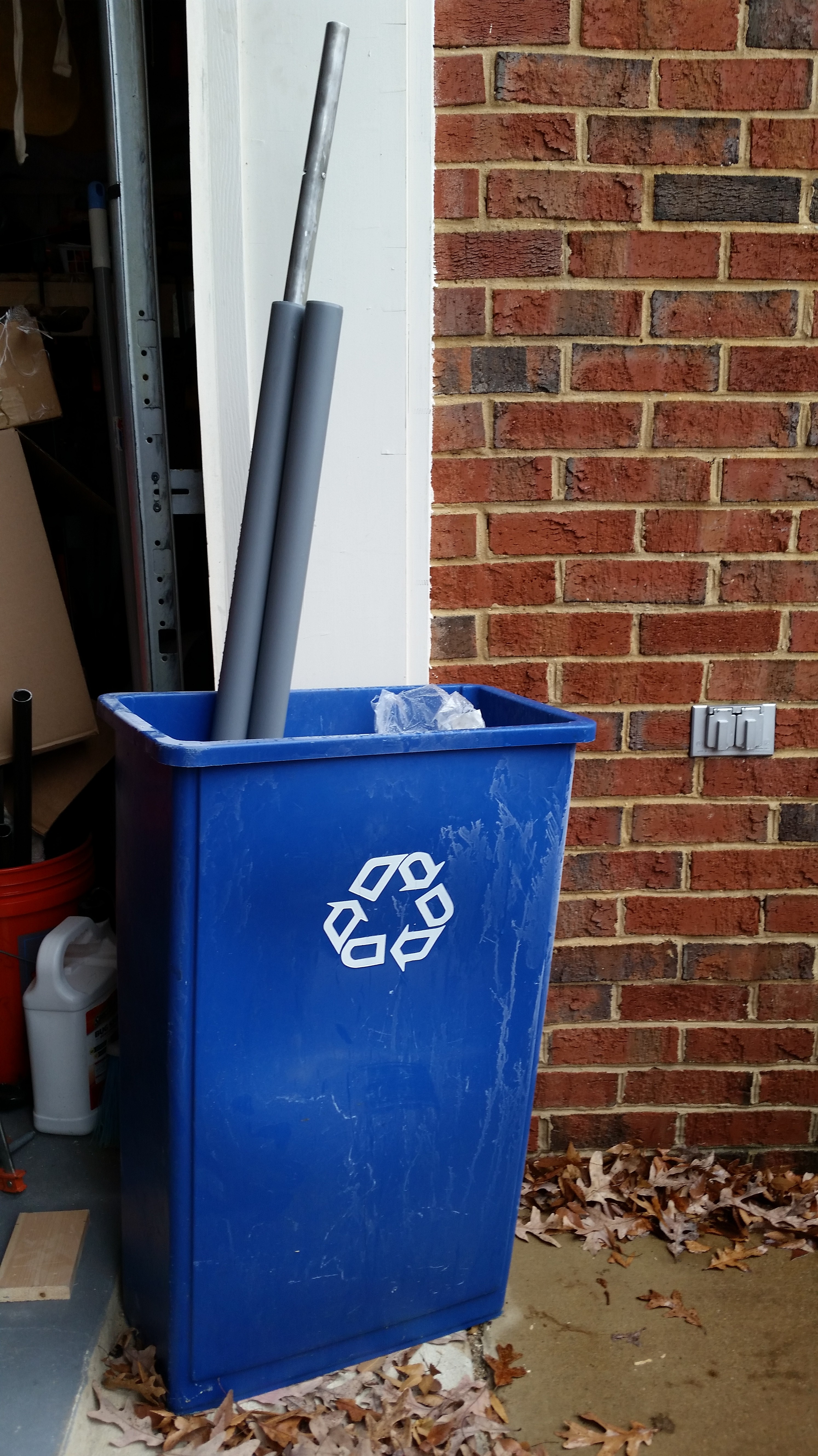
I started off today by sanding down the left elevator tube and then Alodining it.  It was raining lightly so I let the tube soak in the PVC pipes just inside the garage door & out of the rain.  As you can see, to keep the tubes upright I simply stuffed them into my shop recycle bin.
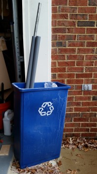
Alodine - environmentally friendly!

In between the extended soaking times of my very weak Alumaprep & Alodine, I measured out the fuselage “saddles” that will keep the fuselage safely atop the fuselage dolly.
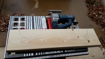
Cutting fuselage saddles

I kept the bottom of each saddle 3-1/2″ high to keep them the same height as a regular 2×4.
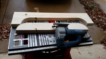
Cutting fuselage saddles

Here’s the first cut “saddle”.

Fuselage dolly saddle

And here are the saddles in place, although not yet mounted.
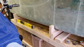
Saddle mock-up

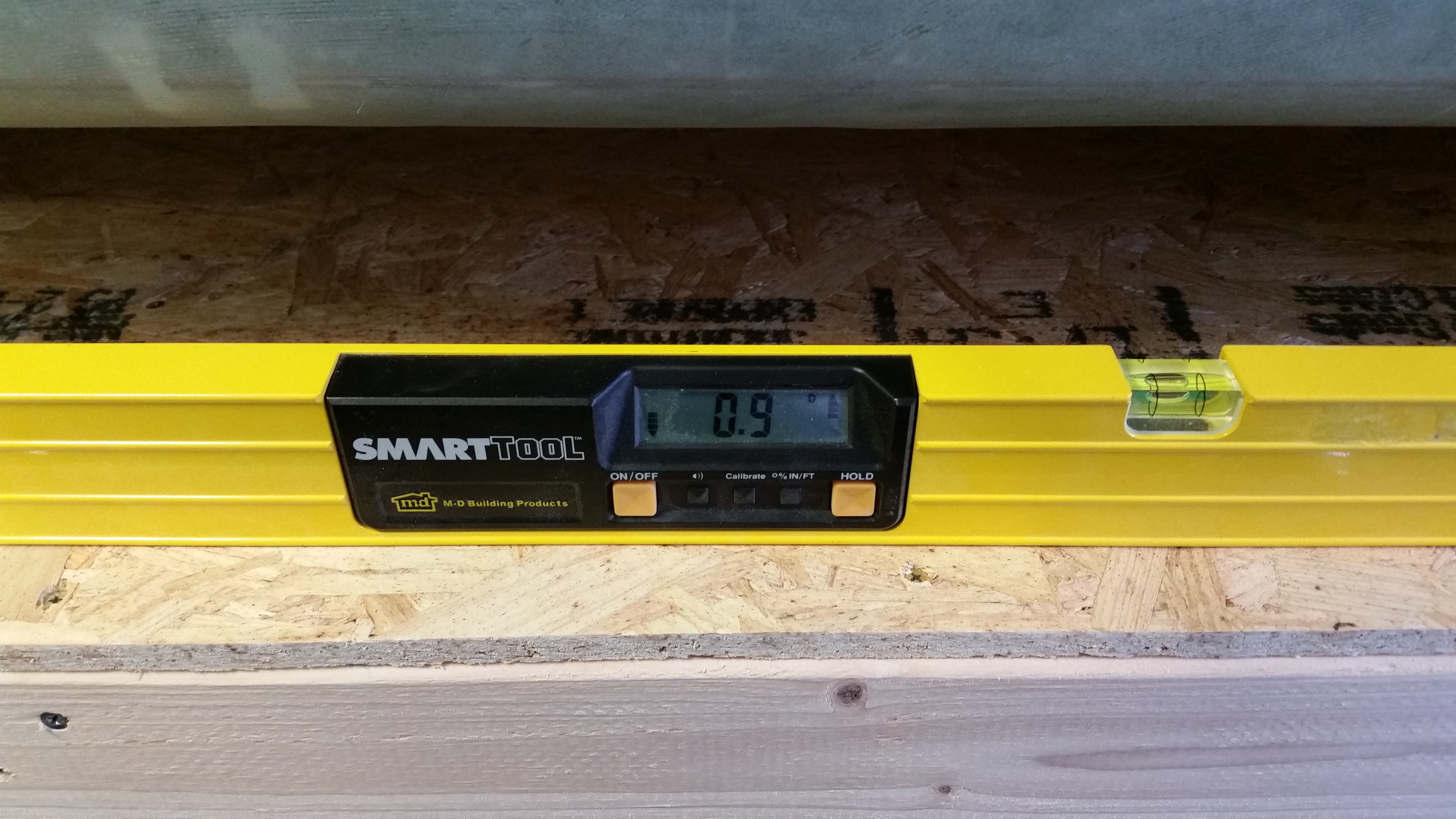
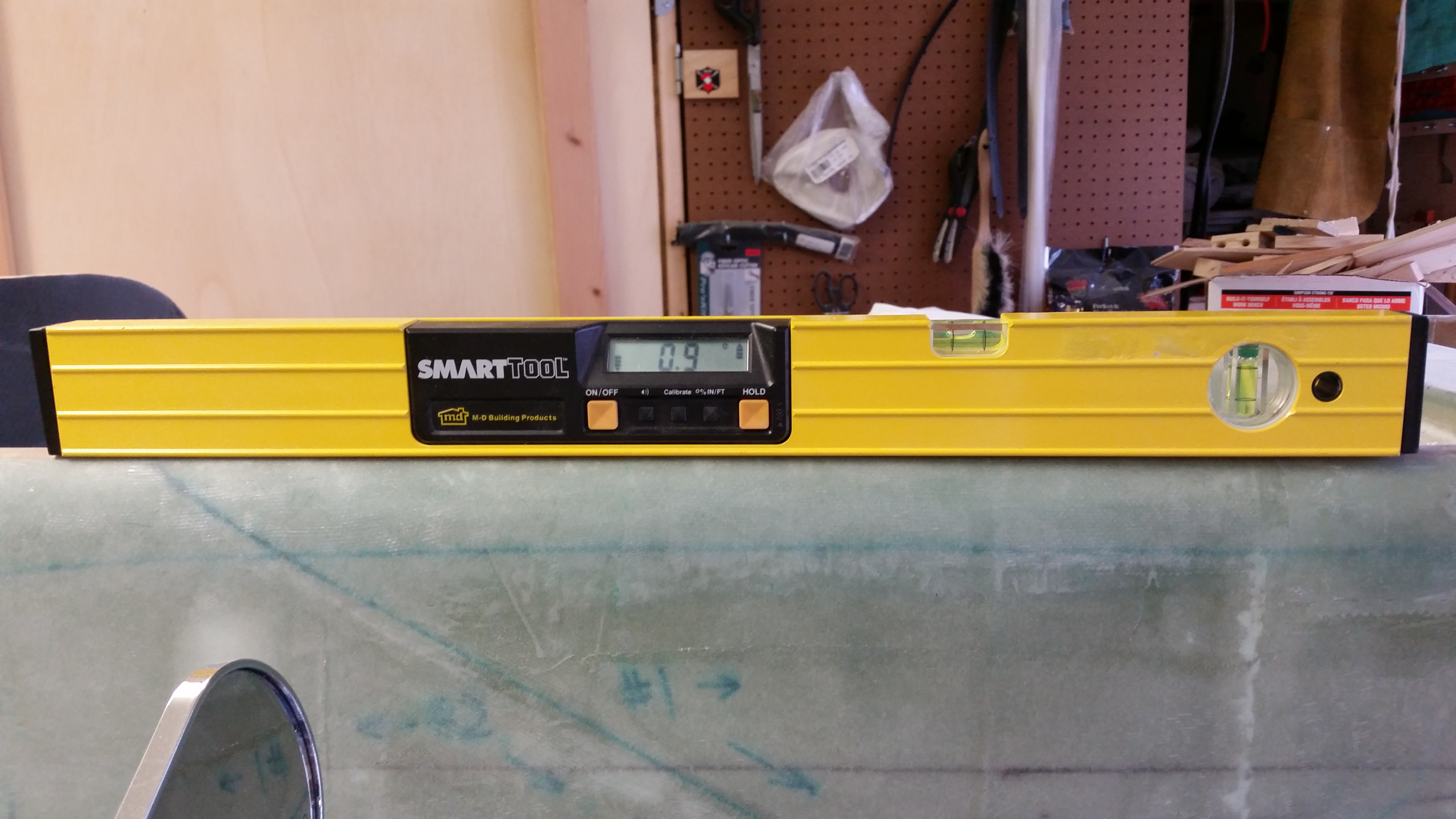
I should note that before I cut the front saddle I measured the angle of the work top of the fuselage dolly.
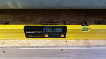
Fuselage dolly top angle

The goal to match the angle of the longerons with that of the work platform on the fuselage dolly.  As you can see, they both came out at the same angle.
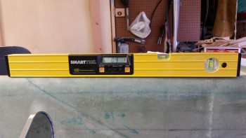
Longeron angle!

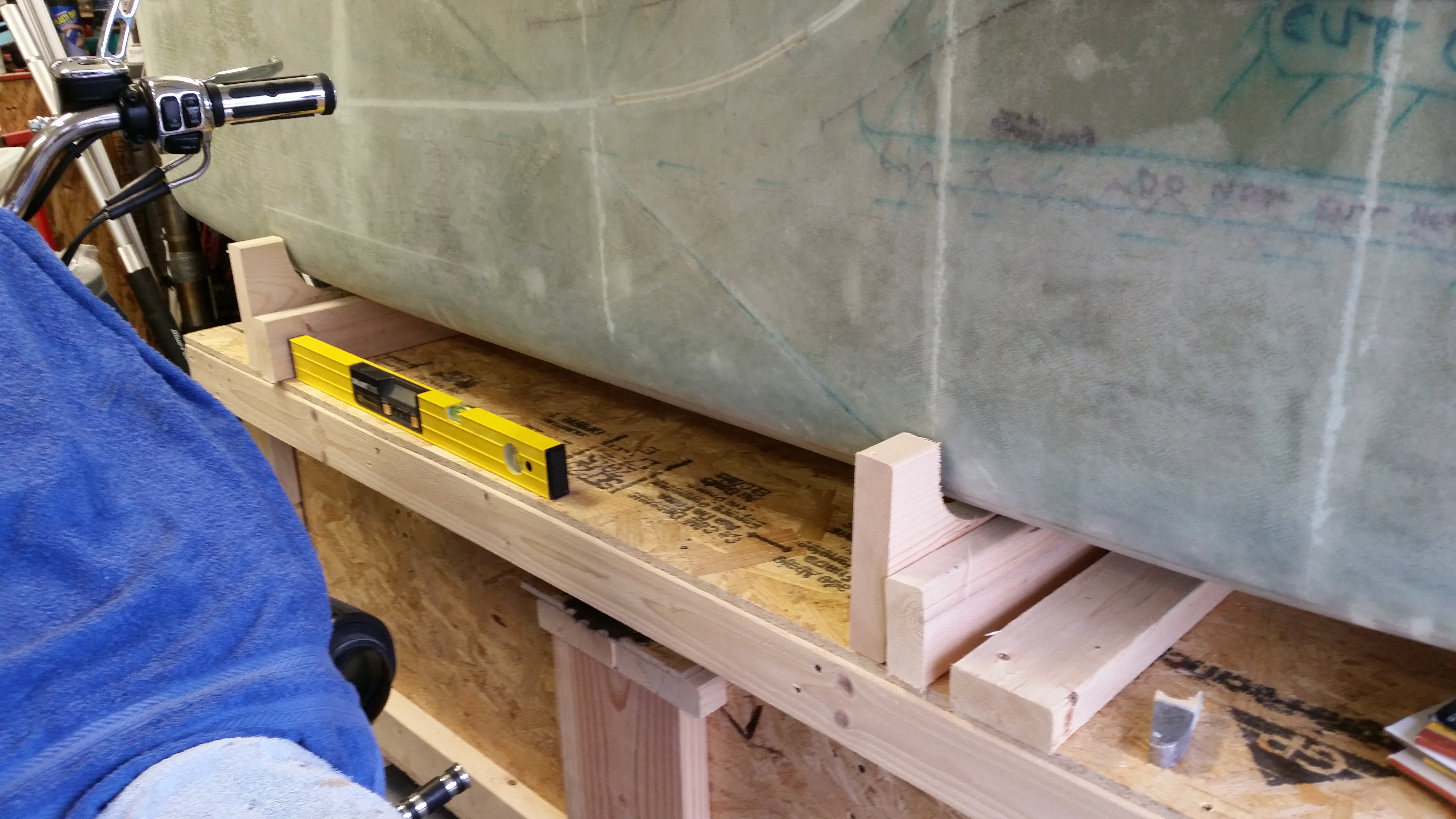
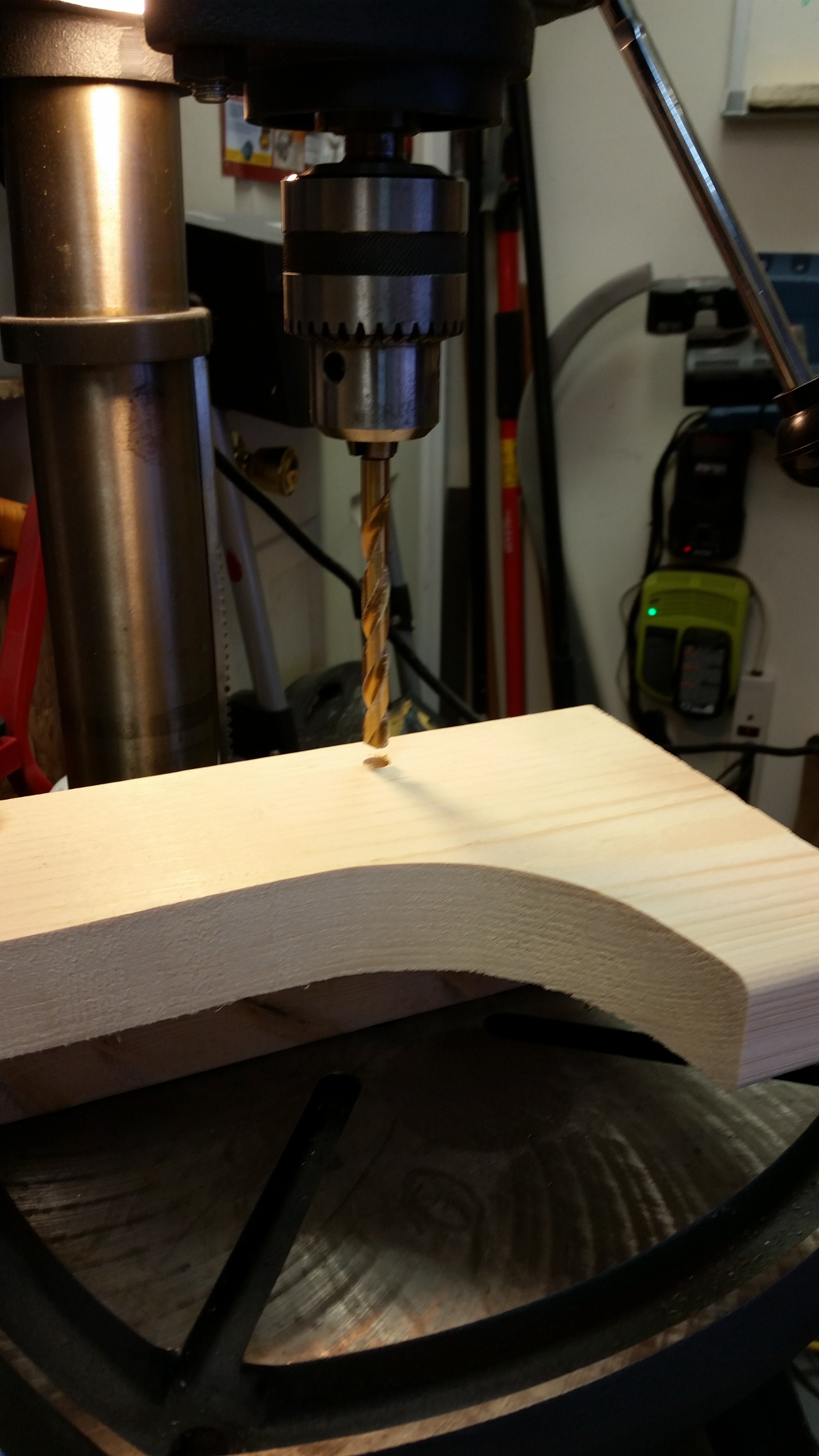
My next task was to drill a 3/8″ hole 4 inches from the side of each saddle into the 2×3 below it.  The 2×3’s will be mounted flat and then each saddle bolted to the 2×3.
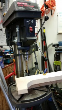
Drilling saddle mount holes

Drilling saddle mount holes

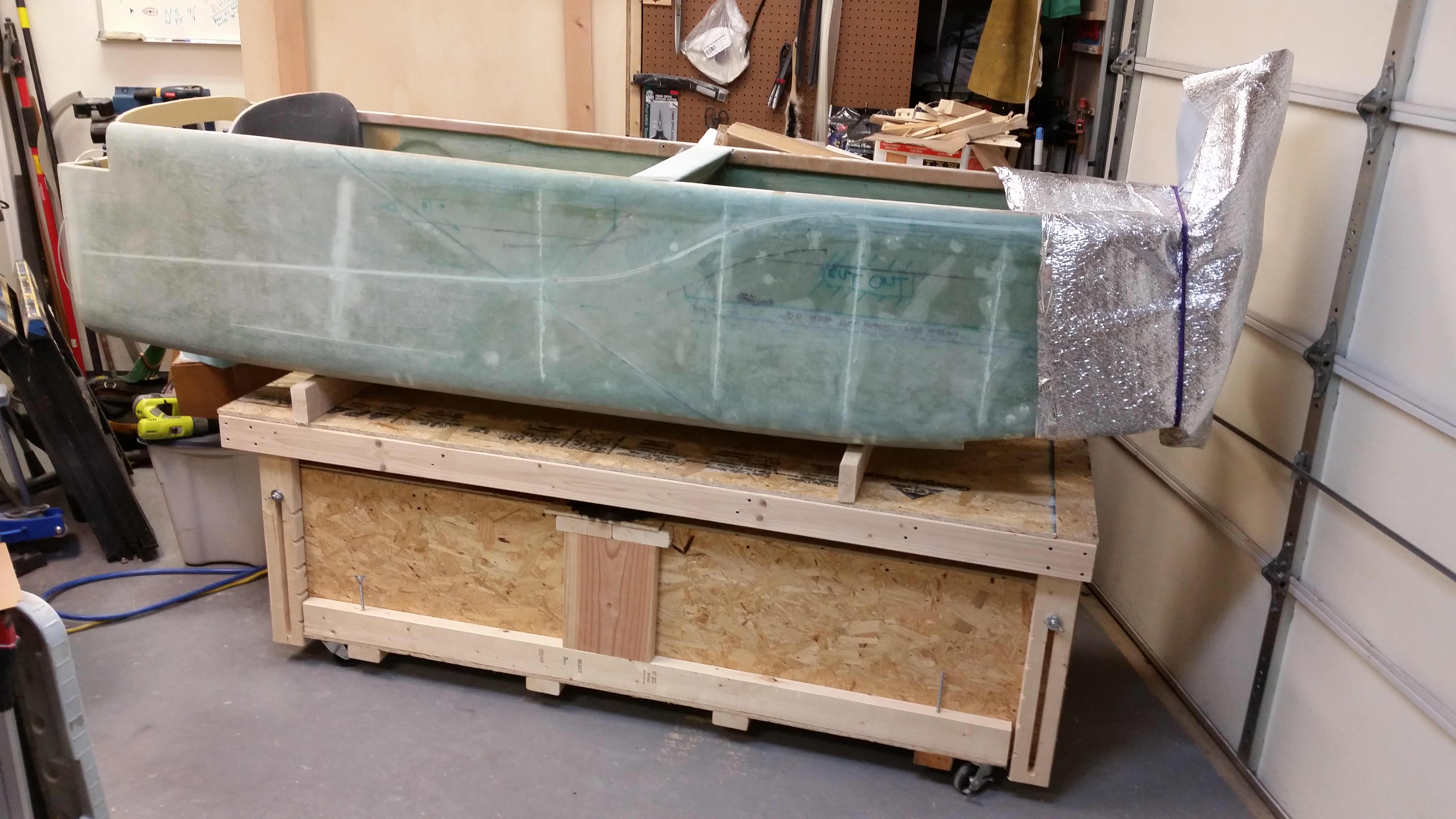
Here’s a shot of the fuselage mounted on the fuselage dolly in the saddles.
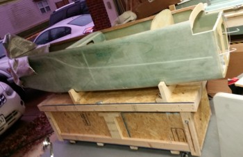
Fuselage on dolly in saddles

I also mounted 3 tie-down points on each side of the fuselage dolly: one next to each saddle, front & aft, and then one in the middle of the work table.
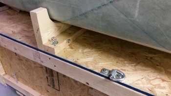
Tie down points

Along with finishing up a lot of tasks on the fuselage dolly, I also reorganized the garage to facilitate the nose build and cleaned up a bunch.  After I finished with my non-build tasks, I got back to work on the left elevator rebuild.

Below is a shot of the elevator tube after the Alodine dried.
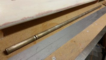
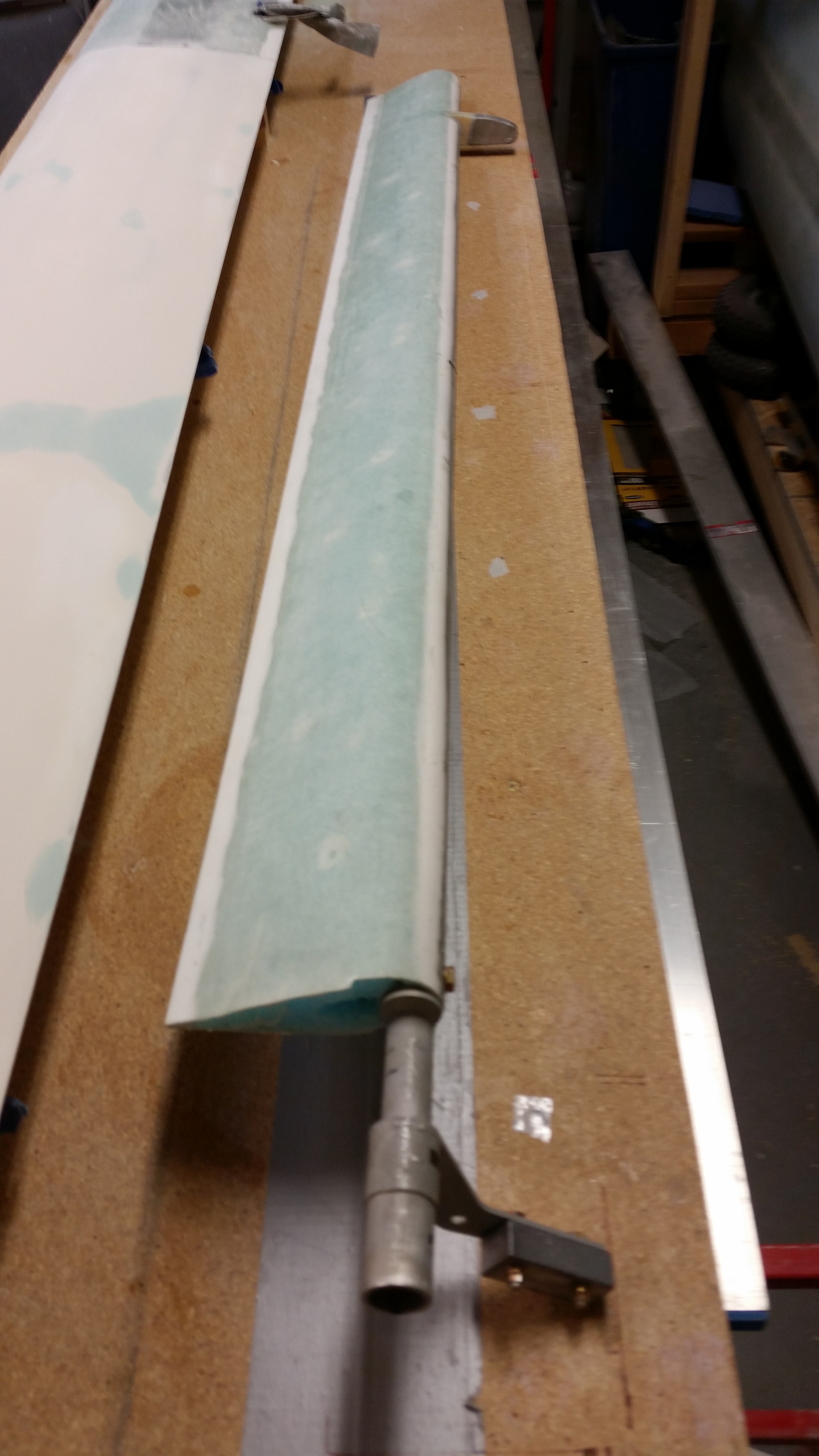
Alodined left elevator tube

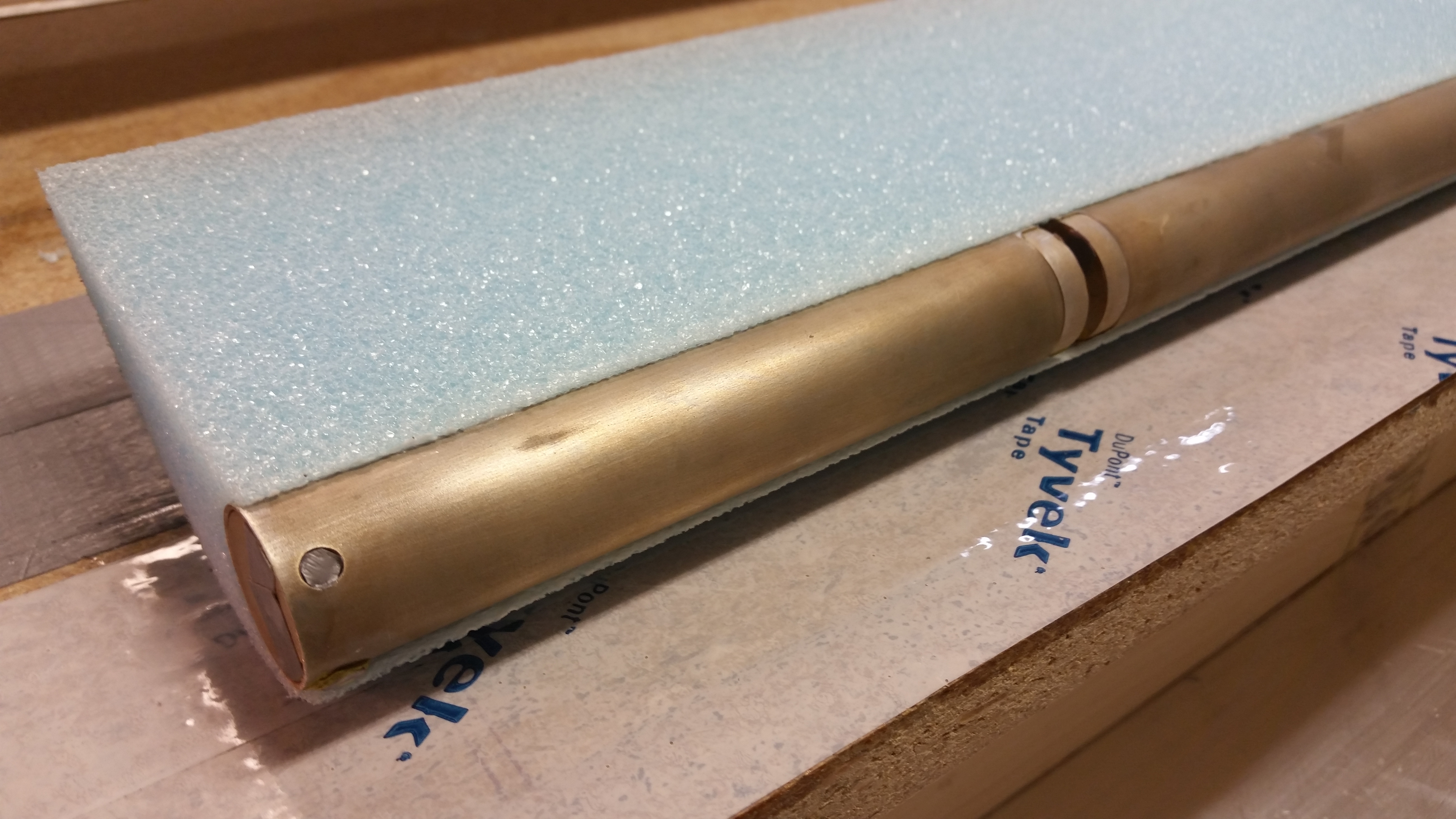
Now, to get the left elevator foam core mounted on the elevator tube so that it matches the right elevator tube, especially the TE, I simply couldn’t build it as if it were a new build. Why? Well, when I originally drilled the elevator tubes to mount them to the torque offsets, which occurred at the same time with both elevators aligned, that action locked in the two elevators so that they were in synch and also ensured that the TE’s matched in trail.

Thus, I had to do a little reverse engineering in mounting the left elevator foam core to the left elevator tube.  I had been pondering this quite a bit over the last week and finally decided to mount the elevator foam core with the elevator tube mounted on the canard, in conjunction with the other elevator tube, spool tube, torque offsets, etc. exactly as it would be in its final install.  In using this method the first step would be to lock the right elevator TE in place, and then that would let me know where the left elevator TE needs to be.

Now, to take this one step further I wanted to mount the elevators to the canard with the canard in a nose down/TE up position.  I pondered on this a bit as well and finally decided on a method:

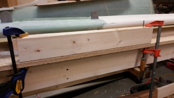
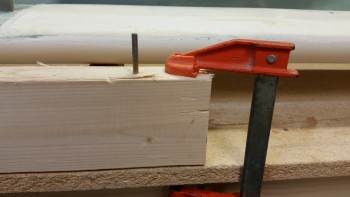
I started by measuring the distance between the LE and the canard mounting tabs, which was about 3-1/2″… obviously the same width as a 2×4.  So I mounted a 2×4 to the work bench with clamps.  I really wanted to avoid (at worst minimize) any damage to the mounting tab holes, so I used a drill bit as a smooth mounting peg on one side by simply drilling the bit into the 2×4 until the cutting edge disappeared into the wood.  I then released the chuck and left the drill bit in the 2×4 (you can see this drill bit on the top right side of the 2×4).
Prepping for canard mounting

Here’s a closeup shot of the drill bit as a mounting peg.
Canard mounting pin (drill bit)

I then used a fine-threaded screw and covered all but the first 25% of the screw threads with electrical tape to mount the other canard mounting tab.
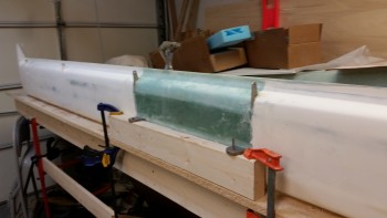
Canard mounted vertical - TE up

The first issue I noted is the mismatch between the TE of the new right elevator and the TE of the right swoosh tip.  Now, I haven’t done specific measurements on the width of the of the elevator, so this may be a passing issue.  Of course I made a note of it and it will have to be remedied in some fashion.
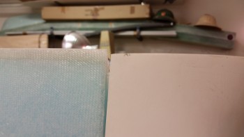
Uh-oh!

I then clamped the right elevator TE to keep it aligned.
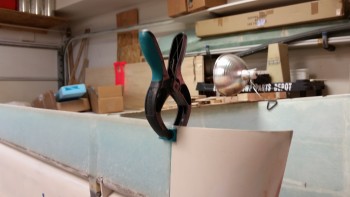
Aligning elevator

Since this evening was all about fixing my elevator woes, it was nice to finally have something go right, as in I’m very happy that the outboard elevator weight fits perfectly into its notched home in the canard.
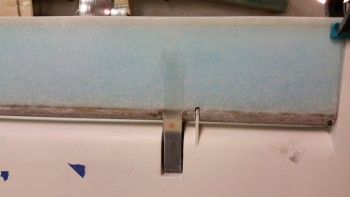
Outboard weight fits!

Here’ are couple shots of the canard with right elevator, et al, mounted.
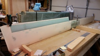
Aligning left elevator core

Now, I have to admit that I just could not get either of the hinge pins into the inboard tube hinge points.  I finally unmounted the canard, laid it flat in its normal right-side-up position and with a little firm coaxing and twisting with vice grips those suckers slid right in.  On the bright side I guess it’s nice to know that they’ll go in when the plane is right side up.  It would suck if it was the other way around!  Yuk, yuk!
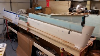
Left TE area taped up

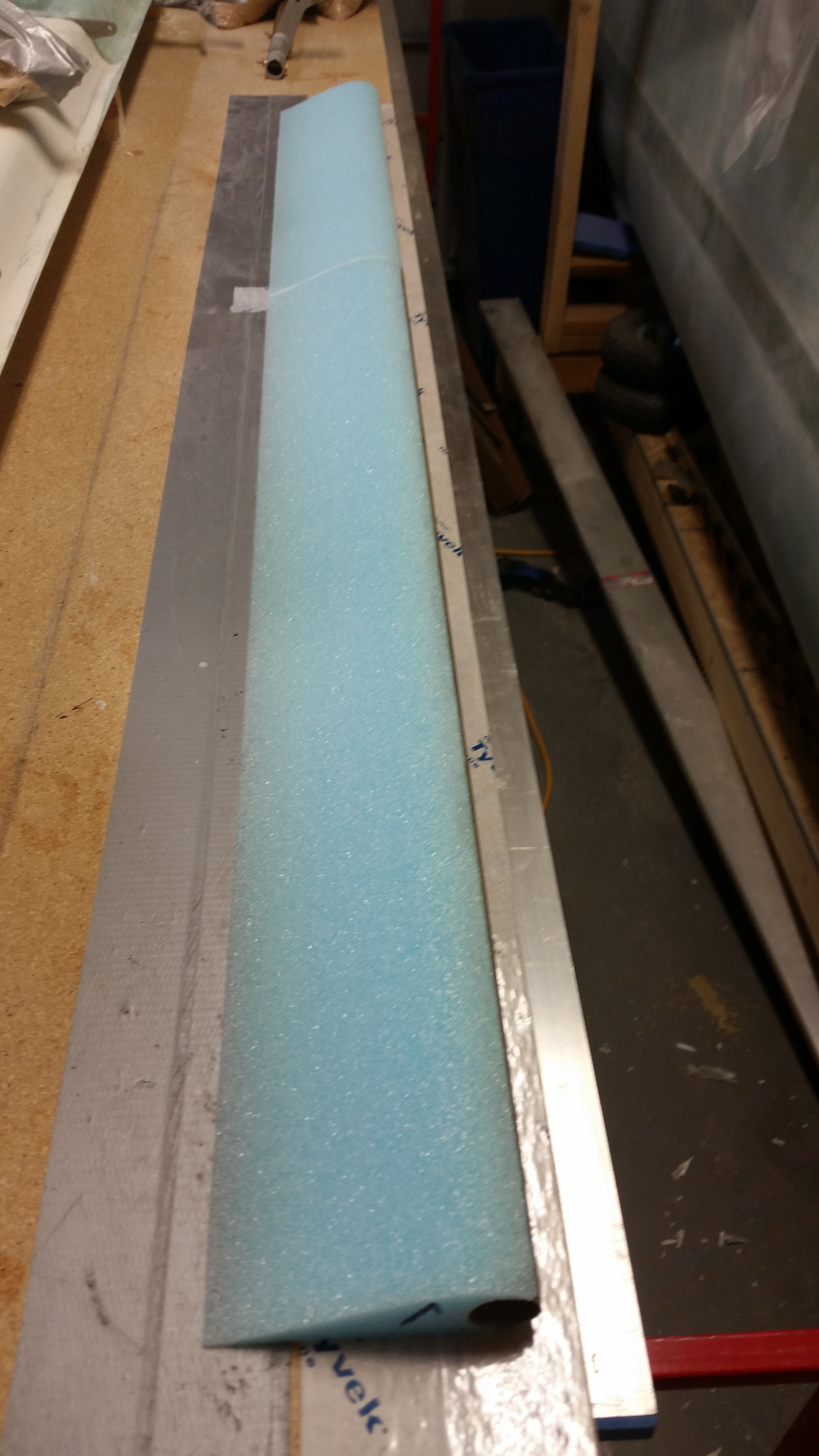
I then pulled out the second set of elevator foam cores that I just recently got from Eureka CNC.
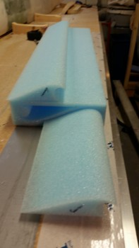
Left elevator foam core

To check how square the ends of these foam cores were I placed them end to end.
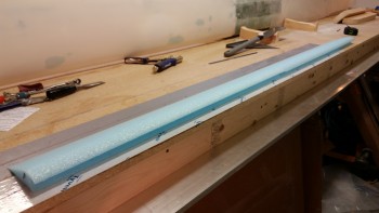
Foam cores end to end

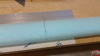
I then measured the paired cores and marked a line at 53″.  I then cut the second foam core and confirmed that the two combined cores equalled 53″.
Elevator foam core marked for cut

To keep the mess on the canard to a minimum, and to also keep the micro’d left elevator core as straight as possible, I decided to only micro the smaller of the left elevator foam cores pieces onto the tube.  To start, I mocked up that smaller piece as you can see below.  It fit perfectly and very snugly.
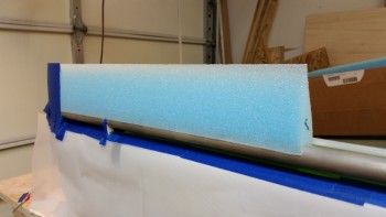
Test fit of smaller foam core piece

I mixed up some micro and micro’d on the smaller piece of the left elevator core.  I ran a line from the right elevator TE to match the left elevator TE as closely as possible in trail to the right side.
Foam core piece micro'd in place

Here’s a wide angle shot of the left elevator core piece installed.
Aligning left elevator TE with right

And a shot from the top side of the canard.
Top side view of right elevator core

I let the micro cure for about an hour before dismantling the elevator assembly.  With the smaller elevator core piece micro’d securely in place, I then merely mounted the remaining elevator core with micro.
Large foam core piece micro'd in place

And then weighed down the elevator core, specifically the TE.
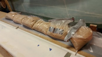
Left elevator foam core weighted

Here’s a shot of the curing left elevator core micro’d to the elevator tube, and a shot of the entire canard back in a “normal” state.
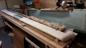
Ah, back to "normal"… ha!

Tomorrow I plan on finishing the major glassing of the left elevator, both top and bottom. As I’ve mentioned before, once I start getting close to finishing the left elevator, I’ll start ramping up more on the nose build.
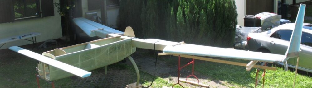
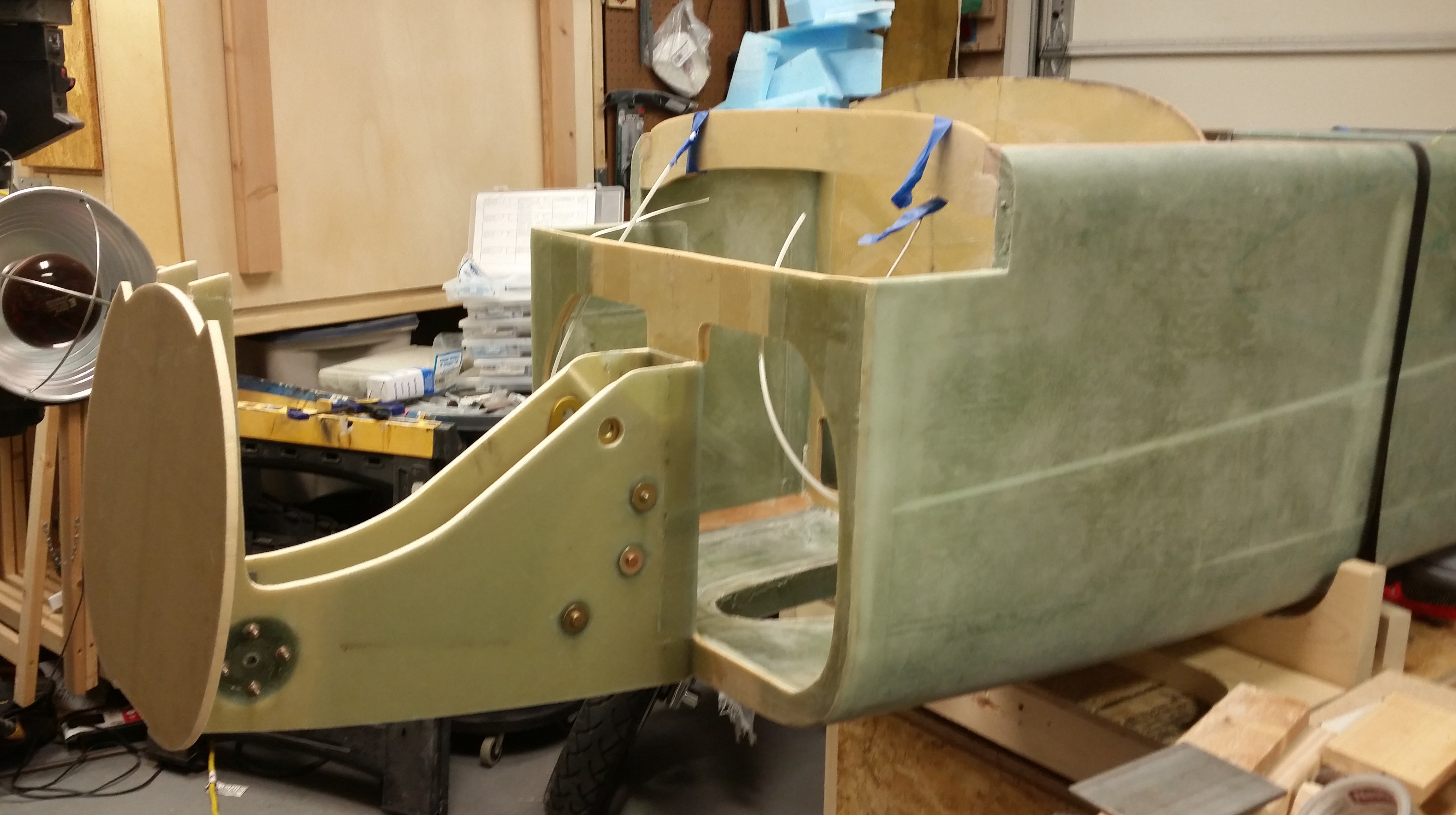


Chapter 11 – Left elevator rebuild

After taking a long hard look at the left elevator I made the call to rebuild it.  The plans say that you can sand the skin down to 1 ply of glass with no issues as long as the areas aren’t too big (around 2″ in diameter).  I met this criteria, the weight was under control after the heavy sanding, but the skin felt just a little too soft in that there was just a bit of give in about 3 of the 5 thinly sanded spots.  My gut told me that this was ok and met the “letter of the law,” but since I have a perfectly “perfect” elevator core from Eureka CNC on hand, my brain said the right thing to do was rebuild this sucker.  I want to be clear, this wasn’t a decision borne of fear, but one of optimization.  I simply want to be able to run this bird as fast as I want to, without worries yes, but the more complete the elevator skin is, then common sense dictates the less prone to structural failure if I do encounter any flutter.

So, I chose to rebuild.

Here is the left elevator when I started this evening.

Left elevator rebuild

I began by removing the torque tube offset on the inboard side.

Deconstructing left elevator

And then I removed the outboard weight.

Removing elevator weight

If you remember, a while back I had a “moment” as I was floxing the inboard elevator hinge bracket into the canard slot.   I had some type of exotherm issue where it spit out a good portion of the flox onto the hinge, torque tube, etc.  The flox even bridged between all these parts and the fishtail area of the canard TE.  I was heading out to meet my buddy Rob, so if I hadn’t found this issue and cleaned it up my life would have been hell for a at least a few days.

Anyway, that incident left some flox on the elevator torque tube offset that I never really noticed until today.  After I removed the installing torque offset, I heated it up with the heat gun on high and then scraped off the dried epoxy.

Removing epoxy from torque tube

This was the result of my cleaning:

Removing epoxy from torque tube

Below is a shot of the “clean” left elevator with all the “add-ons” removed.

Ready to remove glass & foam

Then, as I did with the right elevator, I checked the gaps for hinge slot spacing with the hinge pin and NC7’s installed.

Checking elevator hinge gaps

After I got my hinge spacing set and spacers cut to size, I made my first cut to remove the skin along the top of elevator.

Top elevator glass cut

And then the next cut along the bottom of the elevator near the tube.  I used my trusty Fein saw to make these cuts (BTW, in my shop Fein=Harbor Freight!)

Bottom elevator glass cut

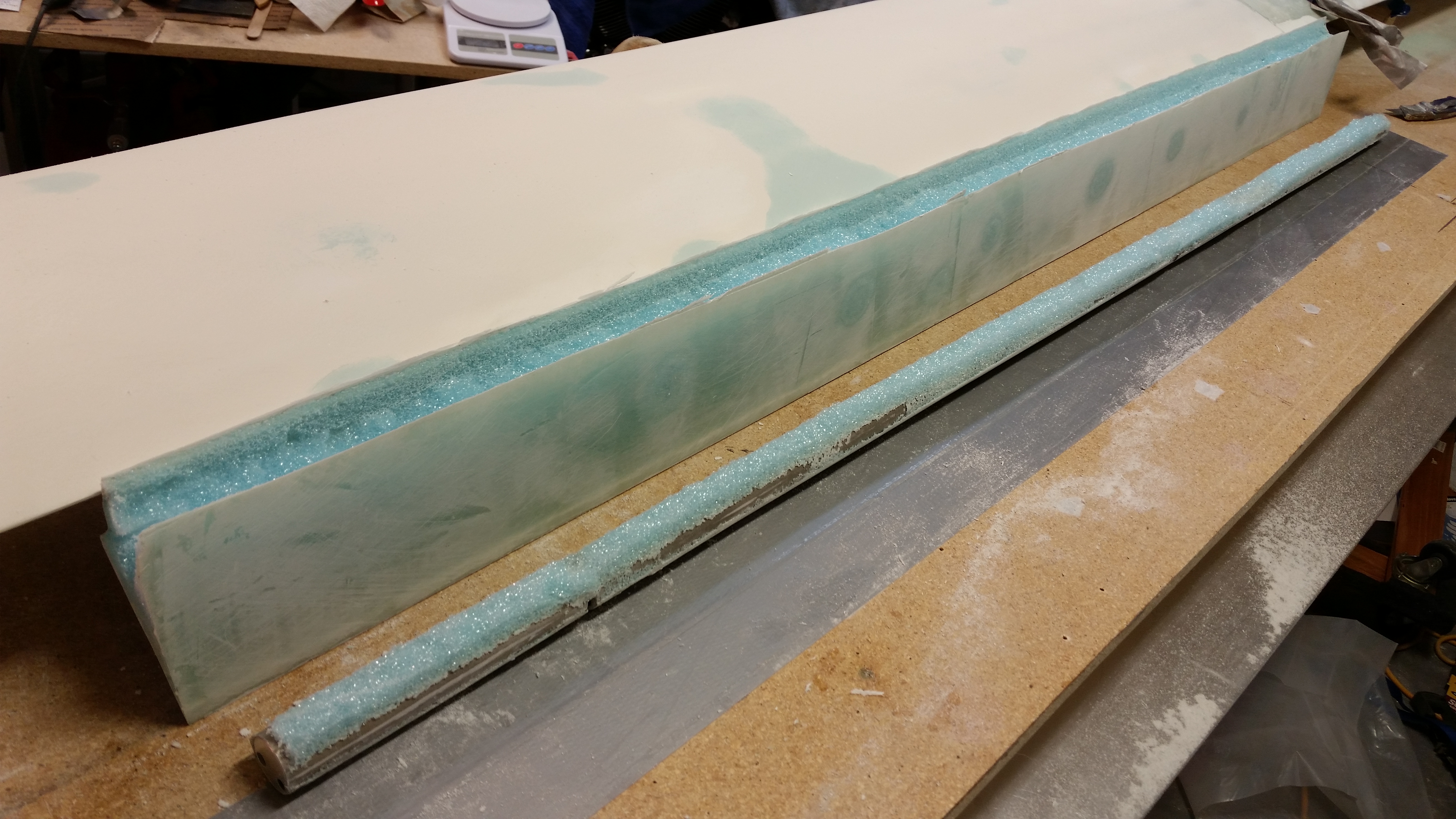
I then extricated the elevator tube from the glass & foam of the now “old” elevator core.

Elevator tube extracted

I cleaned off the old foam & micro with my razor knife in the first round of elevator tube cleaning.

Round one of tube cleaning

Then, just as with the right elevator tube, I dunked it in a PVC tube full of solution.  Only this time I soaked it in acetone vs. white vinegar since I wanted to get this tube completely cleaned by evening’s end.  I figured acetone would probably have a bit more of a “bite” to it.

Soaking tube in acetone

While the elevator tube was soaking, I removed the canard from its mounts and cleaned the leftover Bondo off the mounts.

Canard removed from mounts

With the mounts clean (read: no scratching or gouging the top finish), I flipped the canard upside down.  I was pleased that the Bondo blobs securing the canard to the mounts turned out to be pretty much in as inconspicuous places as I could possible get them.

If you look closely at the pics below, you can see that the Bondo is right on the line of the junction (or corner) where the bottom of the canard meets the fuselage.  Clean up and noticeability in this area shouldn’t be too demanding.

Bondo in inconspicuous spot

Bondo in inconspicuous spot

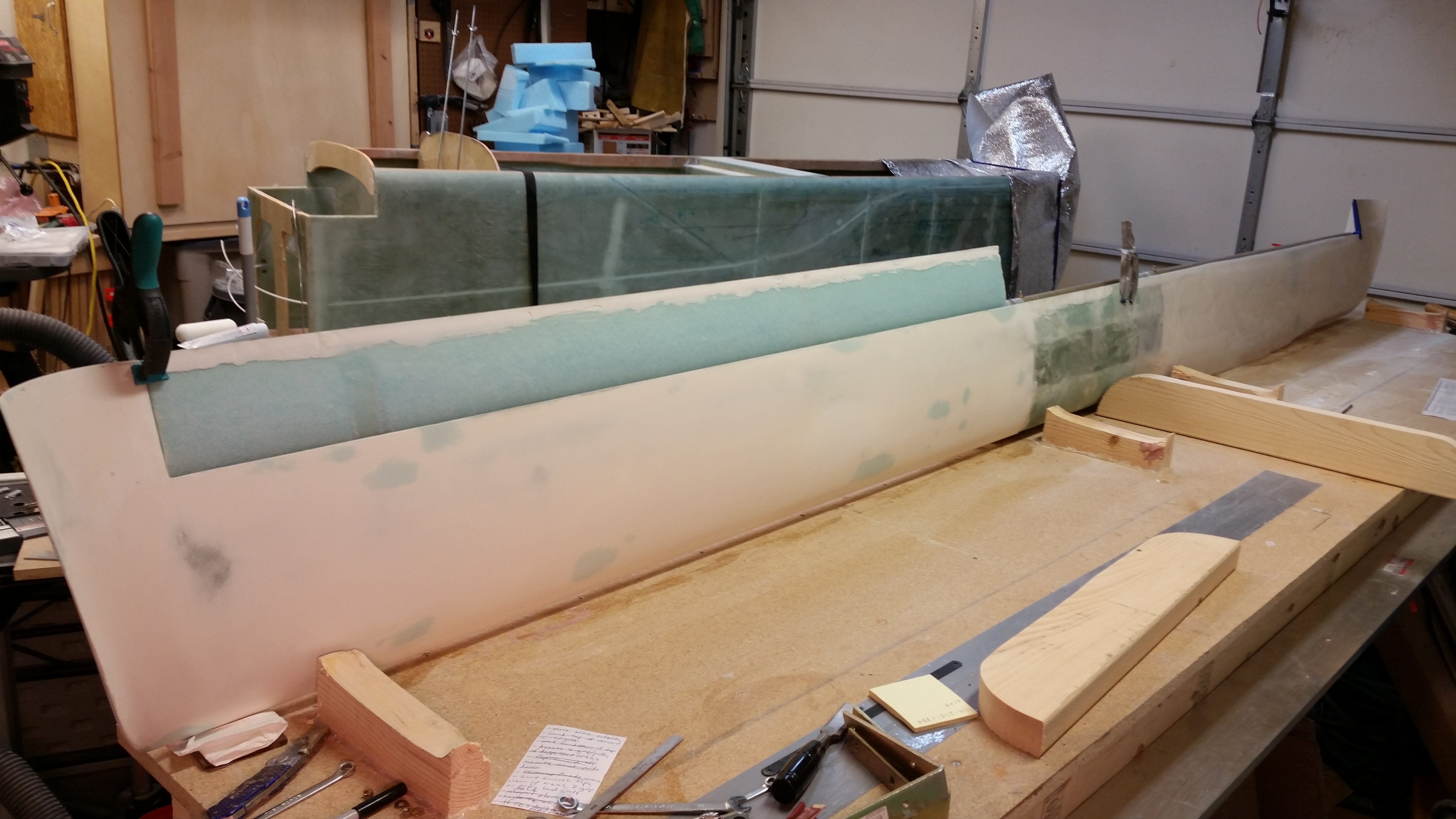
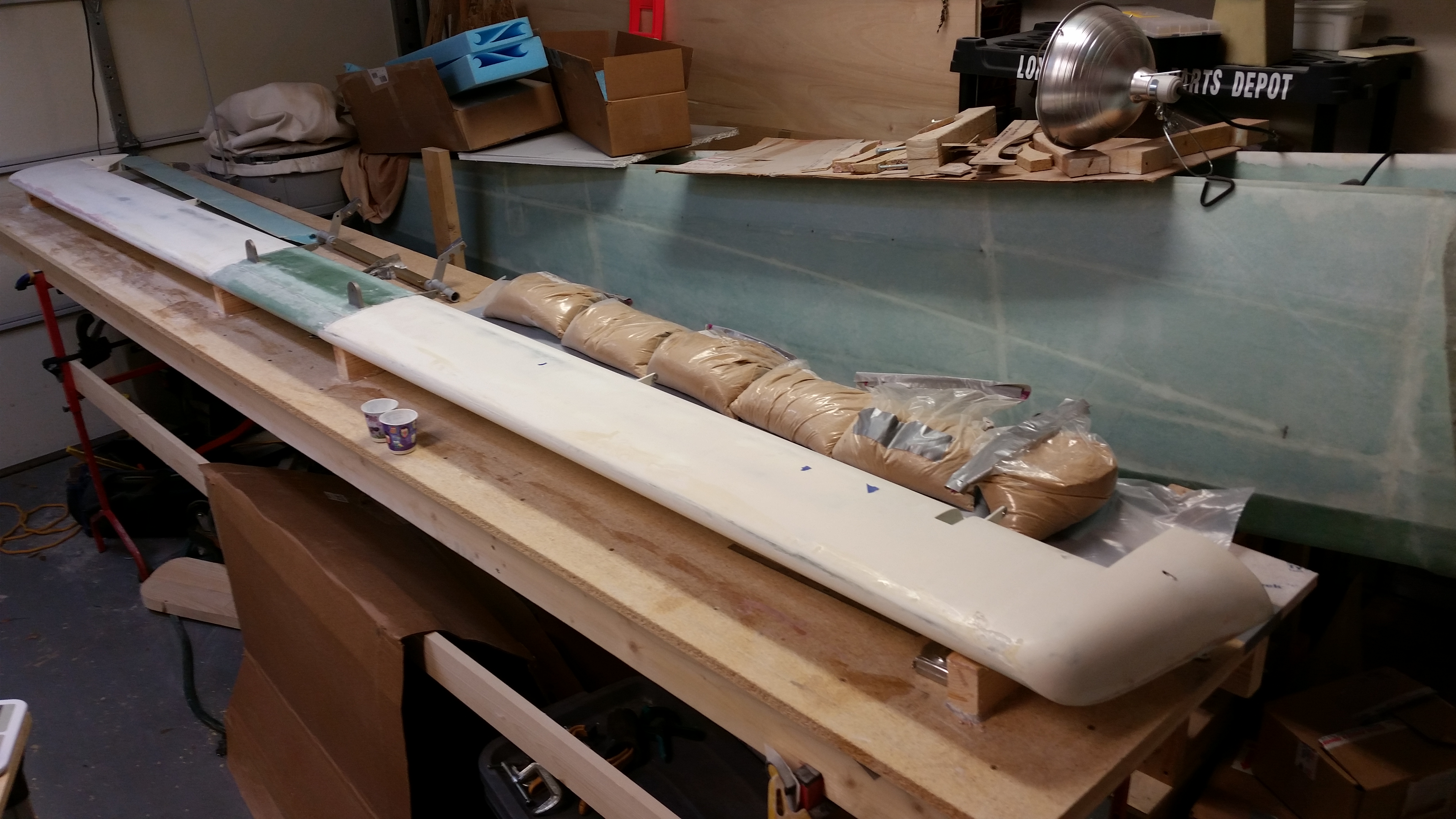
I then took a long shot of the canard –bottom view– that clearly shows that I have a fair amount of work left on the bottom side of the canard as well.

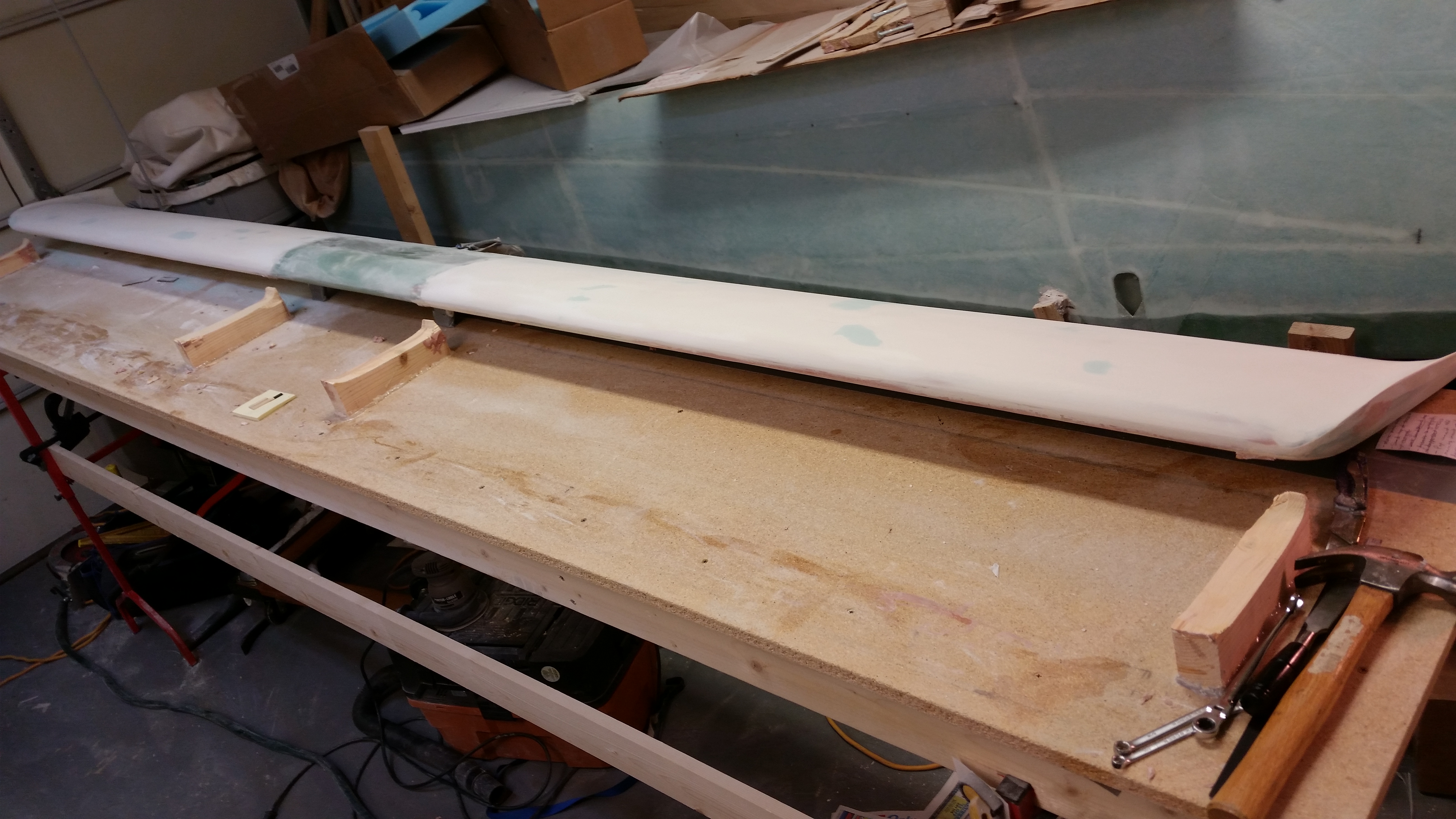
Canard bottom - long shot

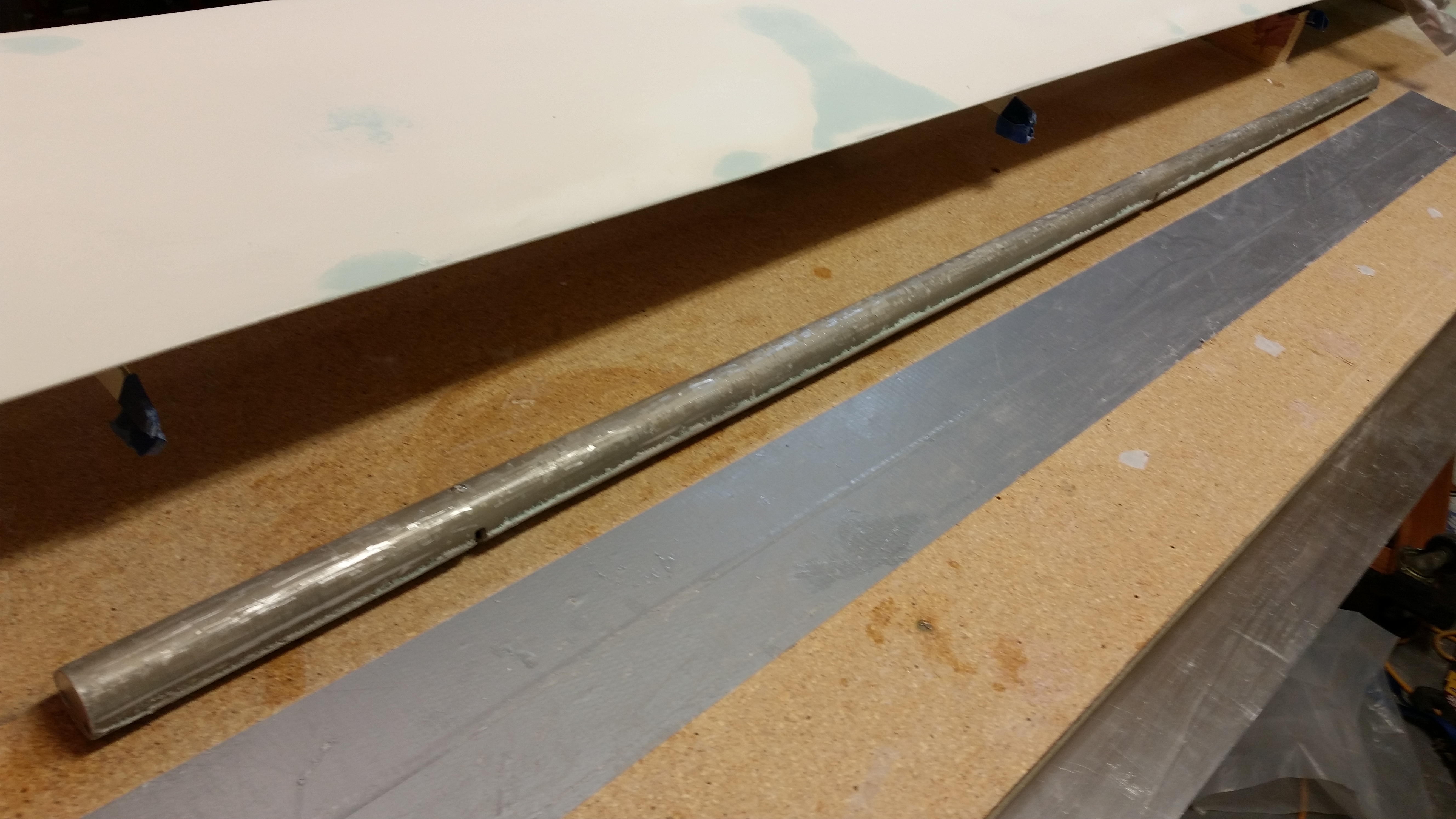
After a couple of hours, I removed the elevator tube from the acetone for its final cleaning.

Note the NG30 assembly to F22 bulkhead clamp in the background for the upcoming nose build.  I drilled and assembled this guy tonight.

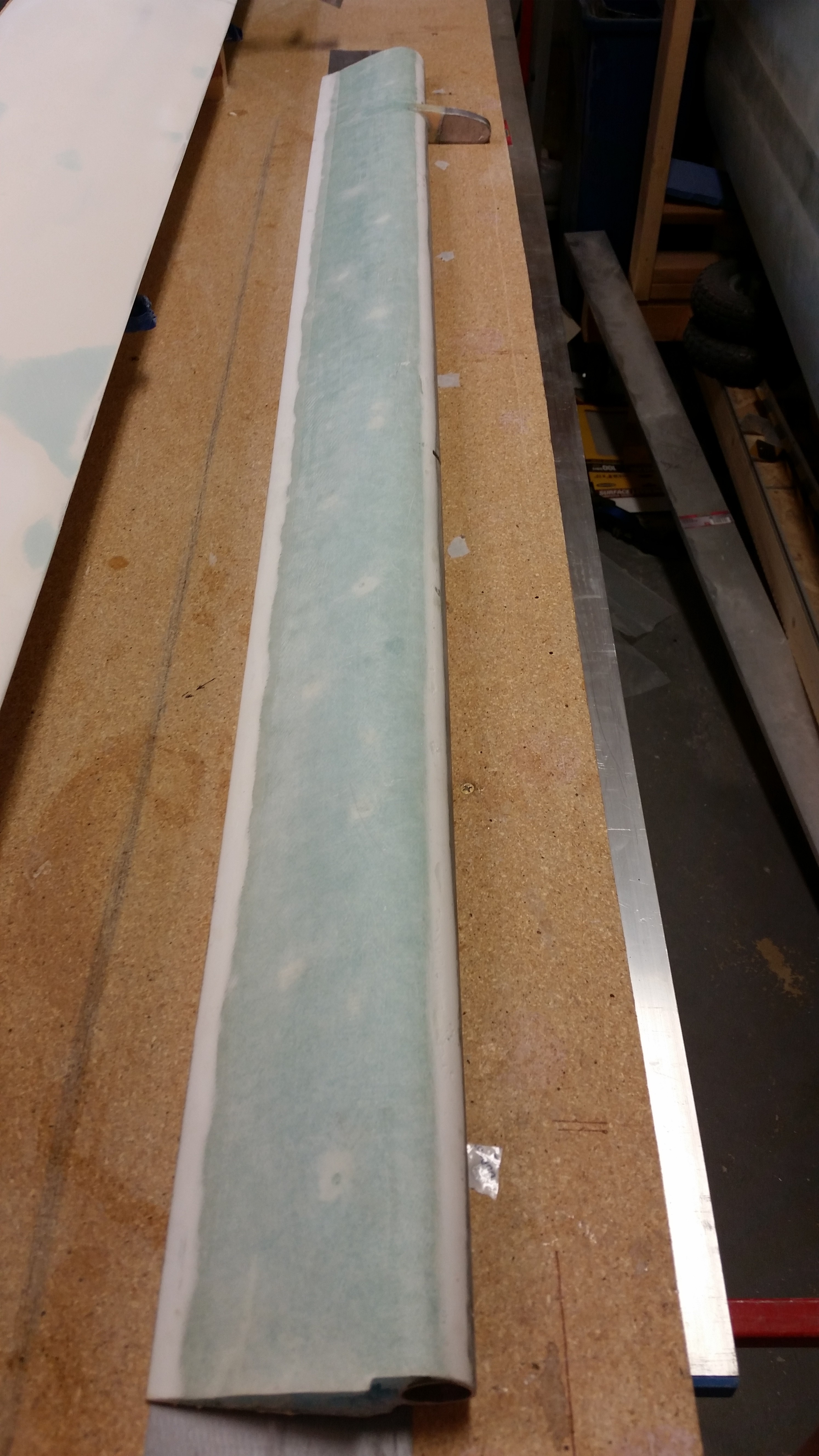
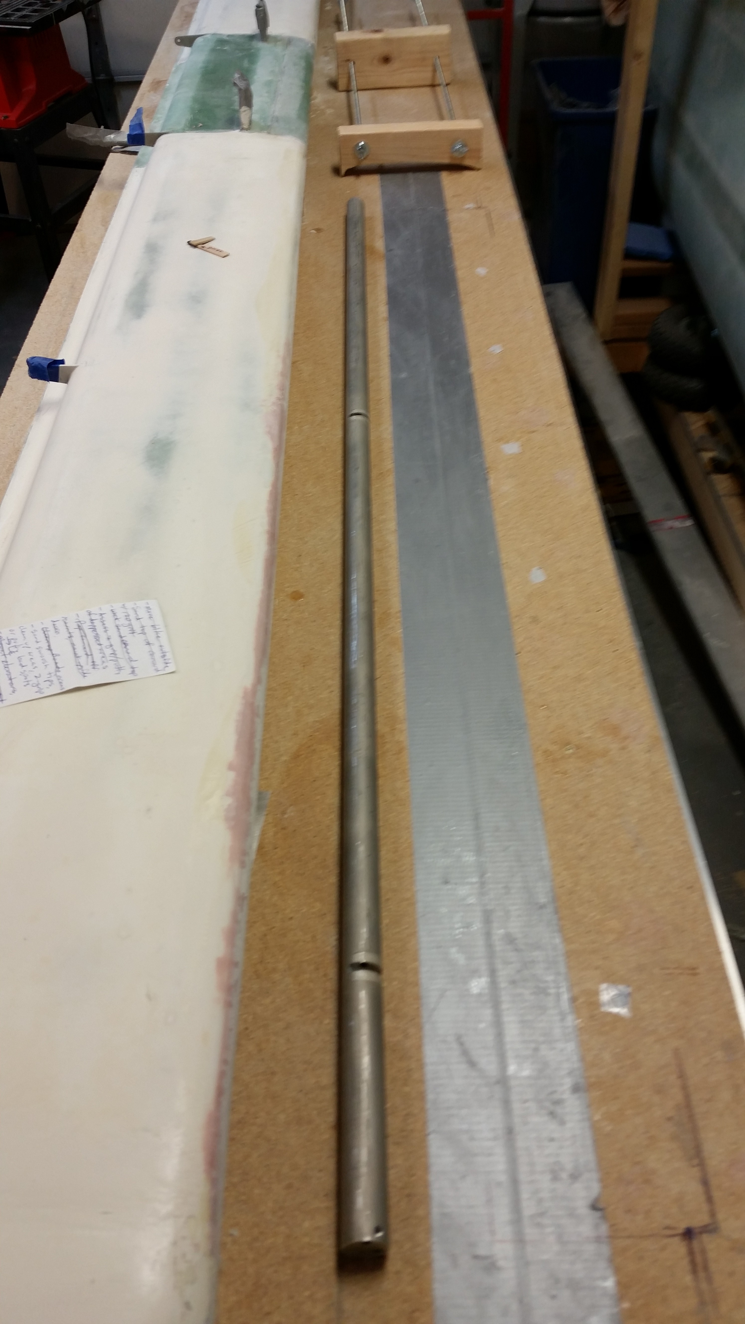
Clean elevator tube

Tomorrow I plan on sanding the elevator tube before Alodining it.  If all goes well I should get the elevator foam core attached to the elevator tube and the bottom skin laid up.


Chapter 25 – Canardly stand it!

Today I had to attend my weekly broker’s meeting at the office.  On the way home I stopped off at Lowe’s, Michael’s and Home Depot in search of some springs for my ratchet pawls for the fuselage dolly.  No joy.  I guess I’ll have to look online for them.

Once back at the house, I started off with finishing about an hour’s worth of research on some of the electrical components, updating my nose wiring/component placement diagram, and a little research on the ADS-B & GRT EFIS interface.

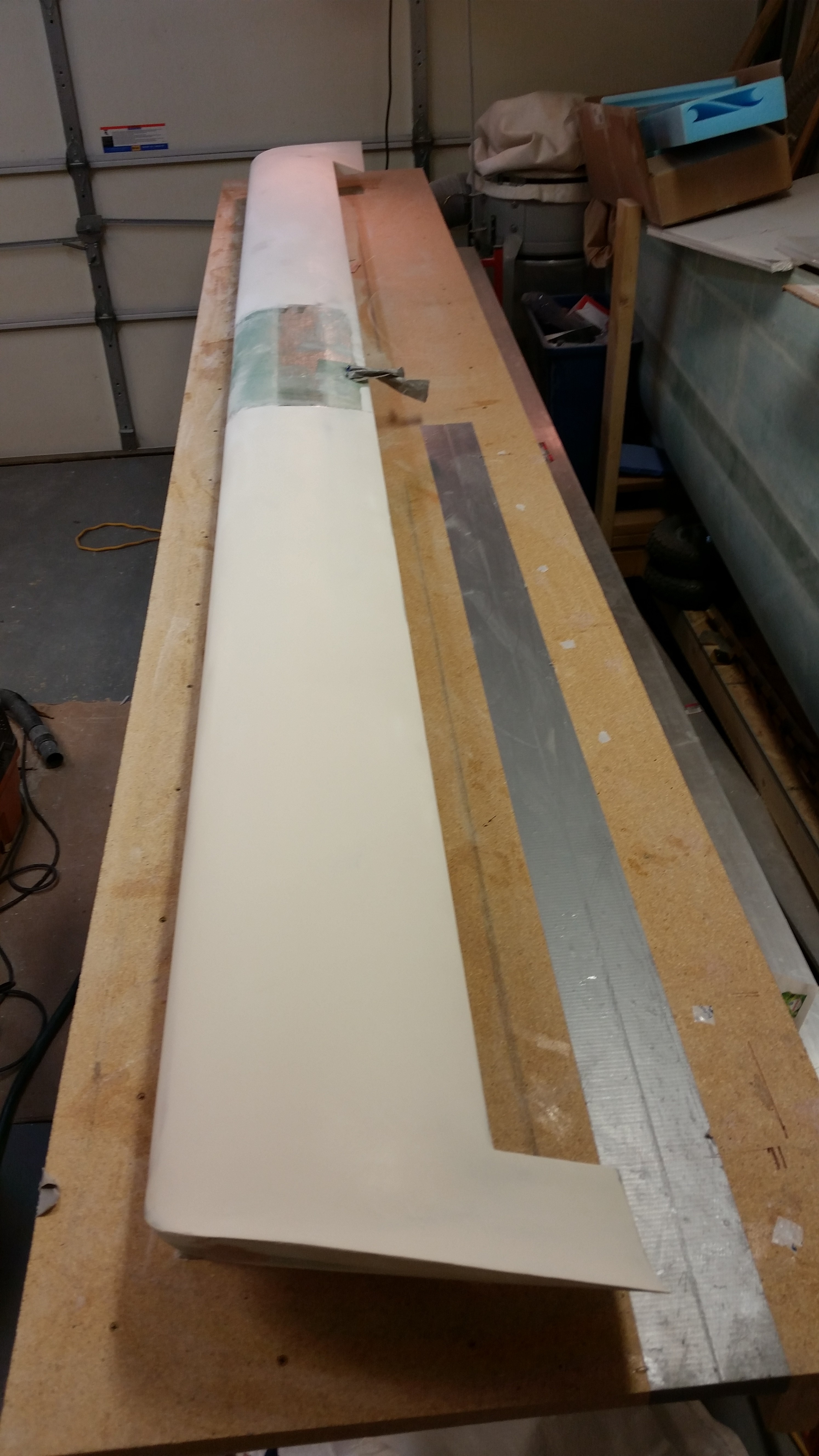
I then spent about 45 minutes sanding the top of the canard with 120 grit paper using the long board.  I’ve got to tell you that sanding it this time around with the primer completely cured was so much easier than the first time around.  The primer sanded very nicely and I was able to get a bunch of it off and the canard top very close to its final shape.
Final primer sand

At this point I was at a bit of crossroads: I still needed to get the canard flipped to mount the elevators, but I also wanted to finish the surface of the canard top as much as possible. Since I haven’t yet decided on a paint system, and thus the required primer, I couldn’t very well just apply a final coat of primer.

Since there are still surface imperfections & depressions, I decided to fill those before moving forward on any other finish actions.  Normally, after a good sanding where so much of the original primer coat has been sanded away, I would simply apply another couple of coats of high build primer and greatly minimize the surface imperfections.  But again, since I’m not sure which primer I’m using at this point, I punted and went with filling all the low areas on the canard top surface.

I started by angling a shop light at the surface from each end of the canard and looking at the surface at a very low angle to find all the imperfections.  As I found each low point I circled it lightly with a pencil.

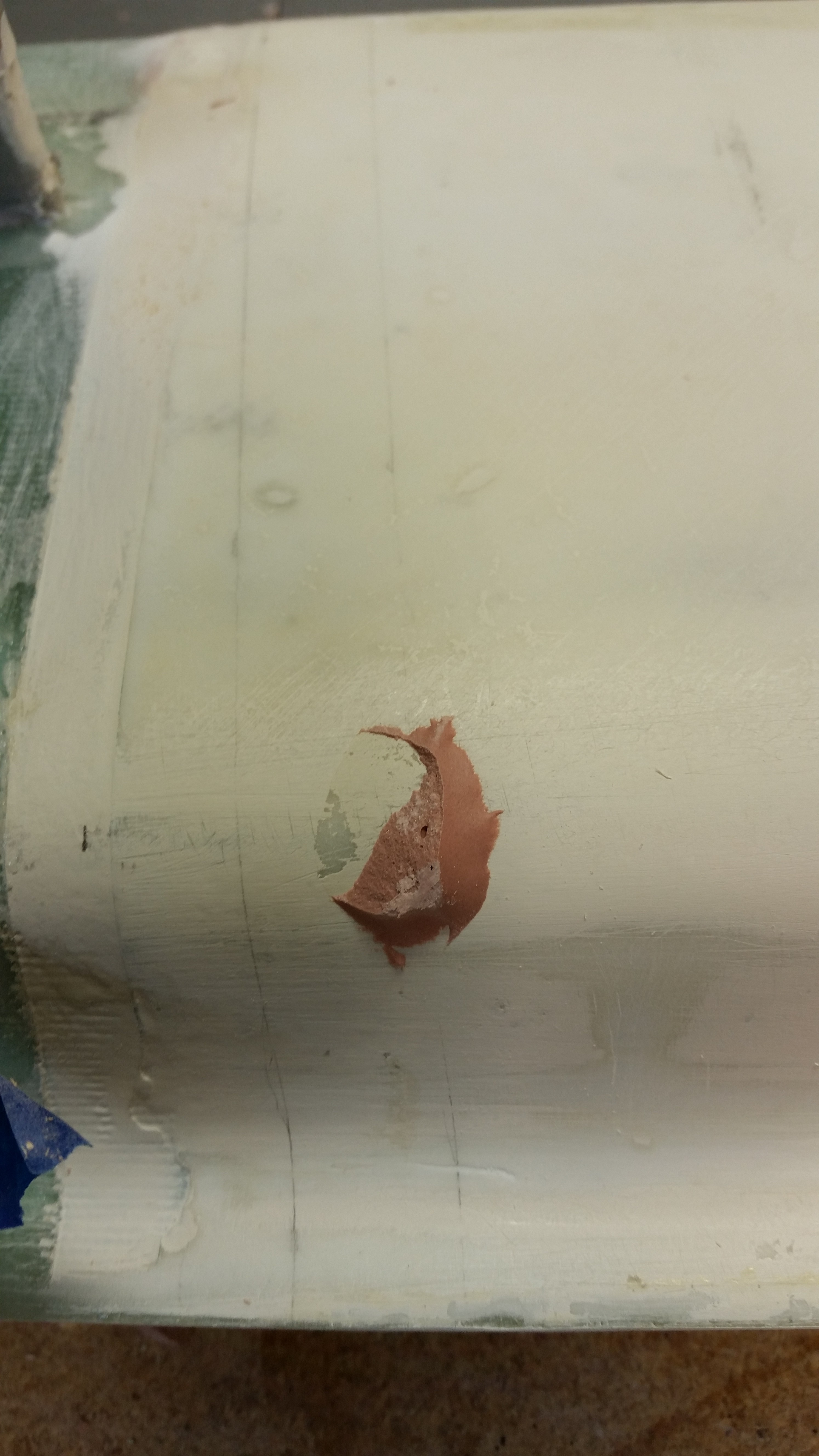
I then popped open a can of Z-Grip that a buddy of mine was storing in my shop and said I could use if I ever needed it.  I swore that I had used this in past 9 months, but apparently not!  I tried stirring this to see if I could revive it, but the ship had sailed on the usability of this stuff.

Uh … Z-Grip no good!

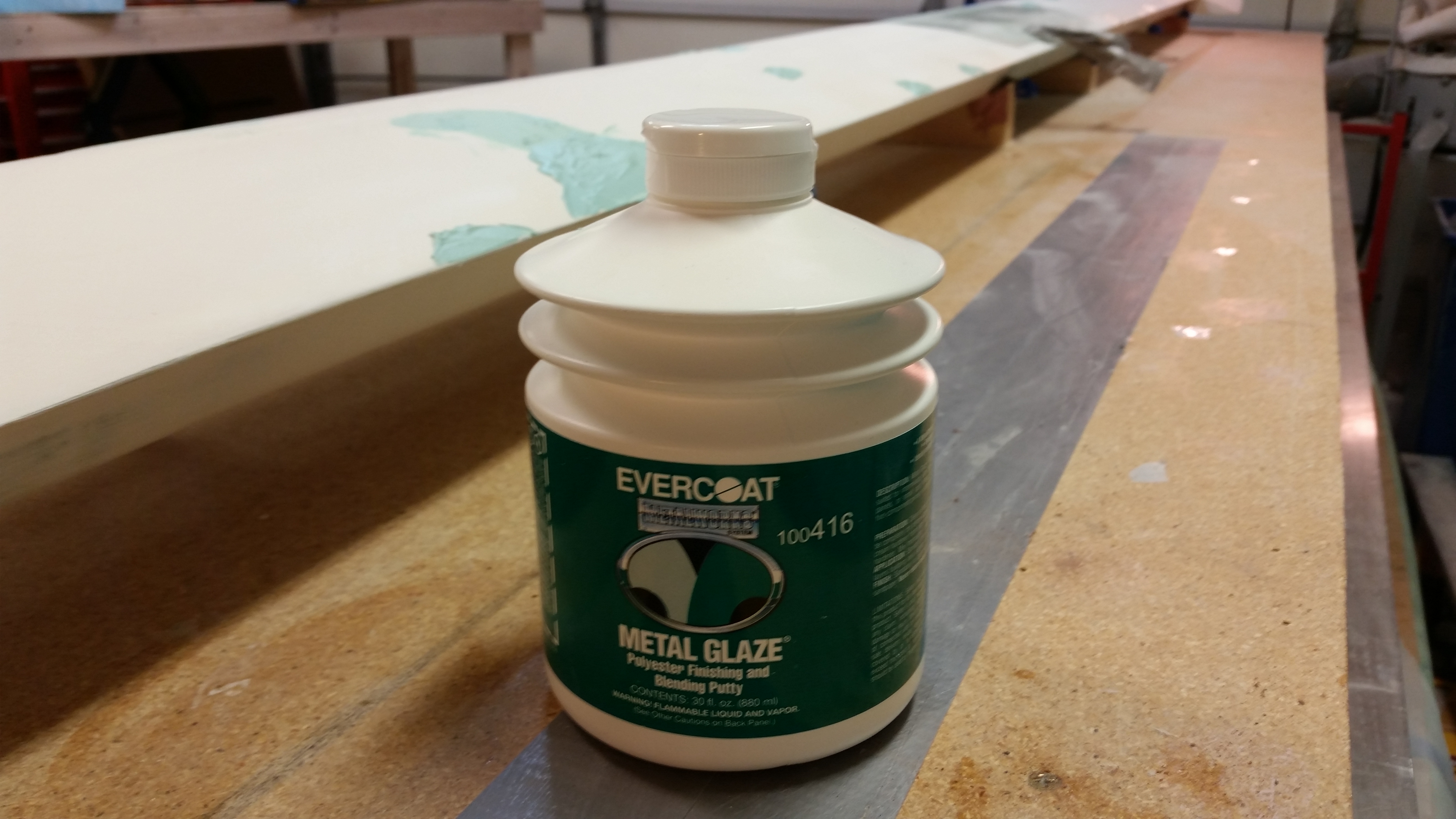
I had even picked up a tube of hardener for the Z-Grip when I picked up the Evercoat Metal Glaze Finishing Putty, and yes, even though it has “metal” in the title, this stuff is a standard high quality glazing putty and works like a champ on fiberglass applications.

It actually turned out better that the Z-Grip was a pile of goo since for my filling requirements the Metal Glaze worked perfectly.  It took 3 separate mixing sessions and about 15 minutes to get the low lying areas filled.
Fresh Metal Glaze

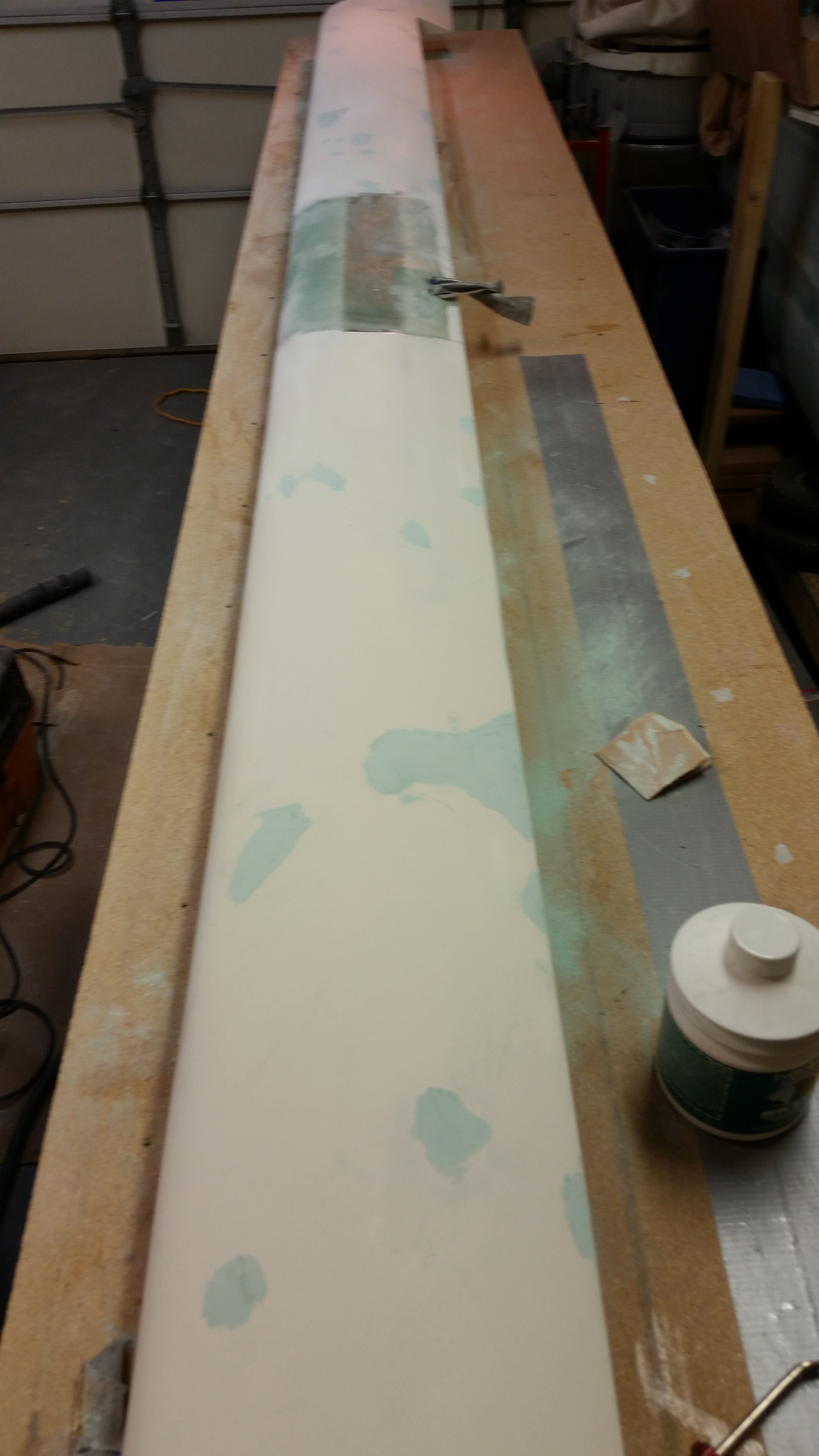
Since the glazing putty cures so quickly, I immediately started cheese grating it to get each spot down close to its final level, using 80 grit strips that I cut out from some used long board sandpaper that I was going to throw away

Puttying depressions

Here’s a shot of the right side after cheese grating the glazing putty spots.

Puttying depressions

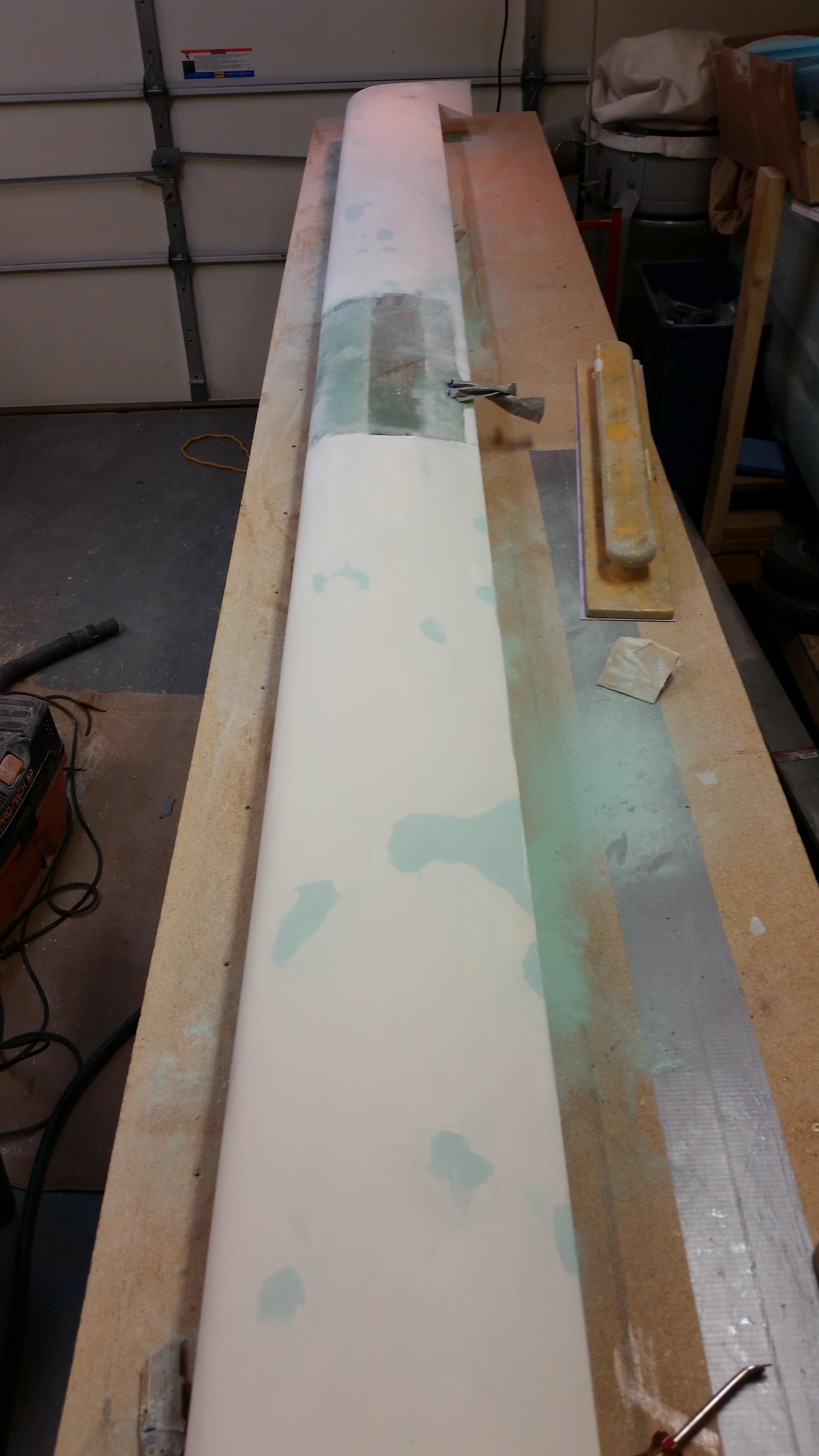
After returning from dinner, I mounted some peel-n-stick 80 grit paper to my sanding block and sanded just the puttied areas.  I got them really close to their final level, feathering the edges of each puttied spot to the existing canard surface.

Cheese grated putty

After the lion’s share of the feathering was completed with the 80 grit hard board, I then loaded up another sheet of 120 grit on the stiff long board and sanded down each side of the canard, focusing of course on ensuring that the puttied areas were blended nicely into the existing canard surface.

Final sanding

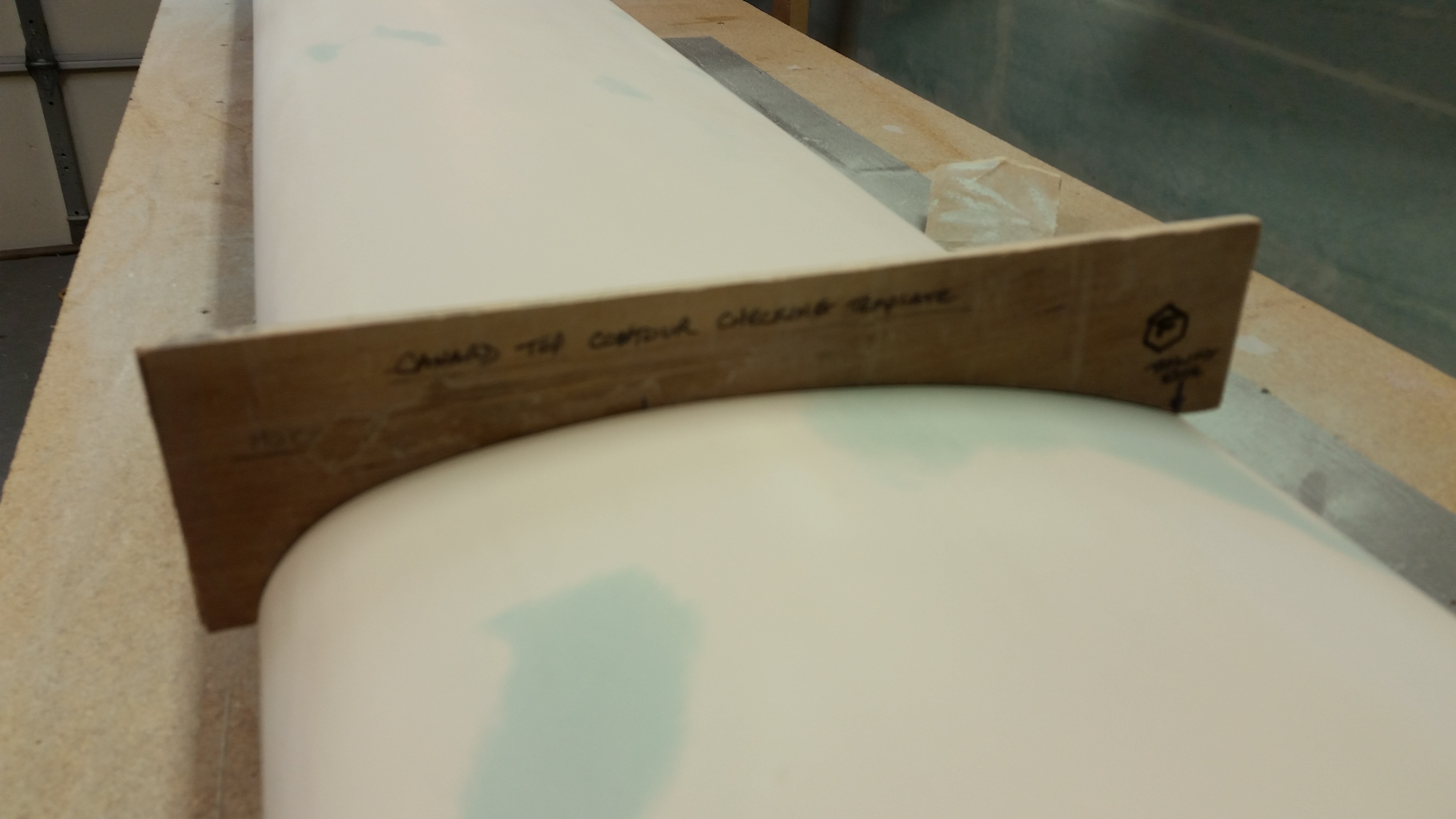
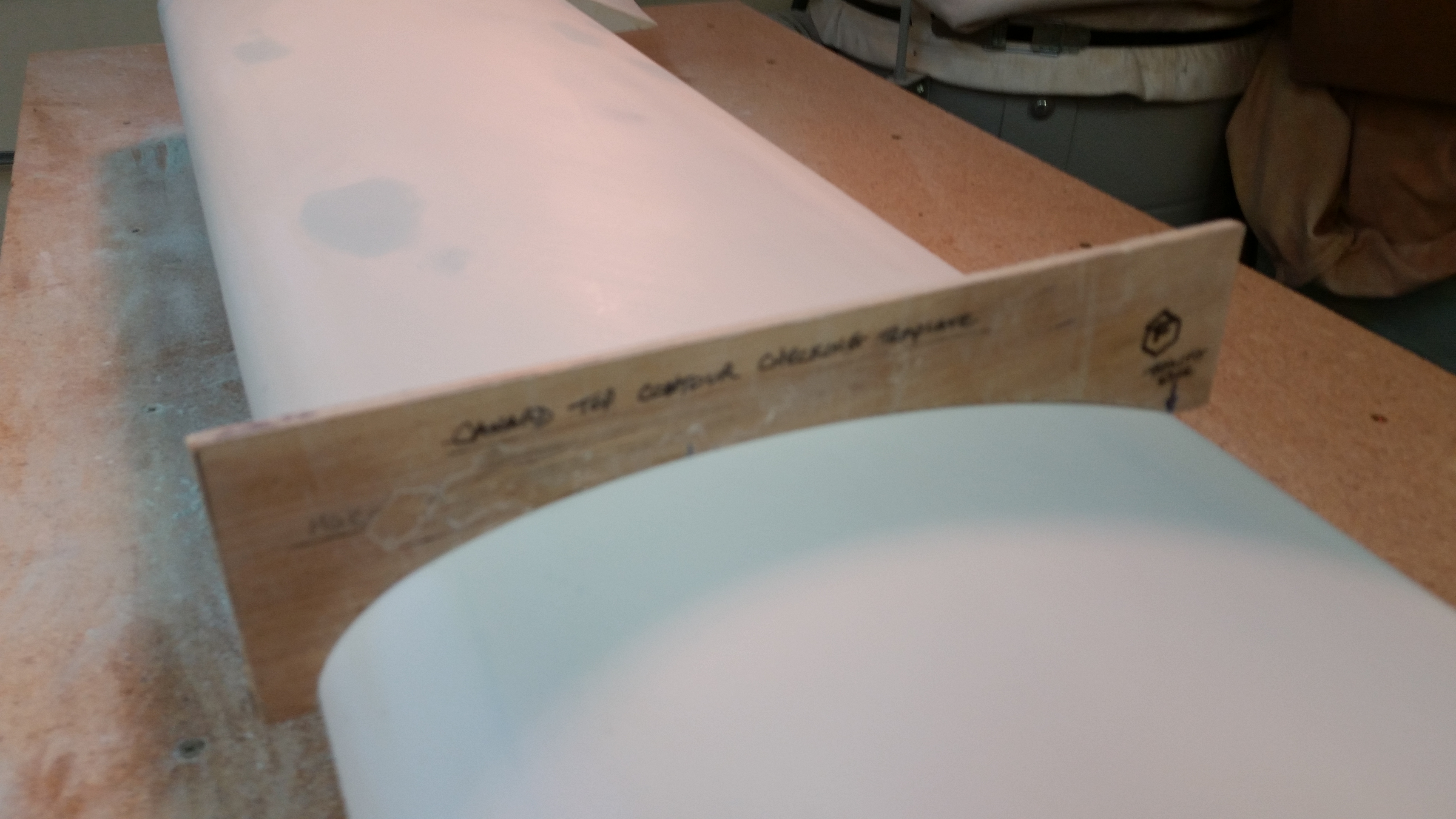
I then checked the profile with the top canard contour template on each side, and was very happy with the results.

Checking left side contourChecking right side contour

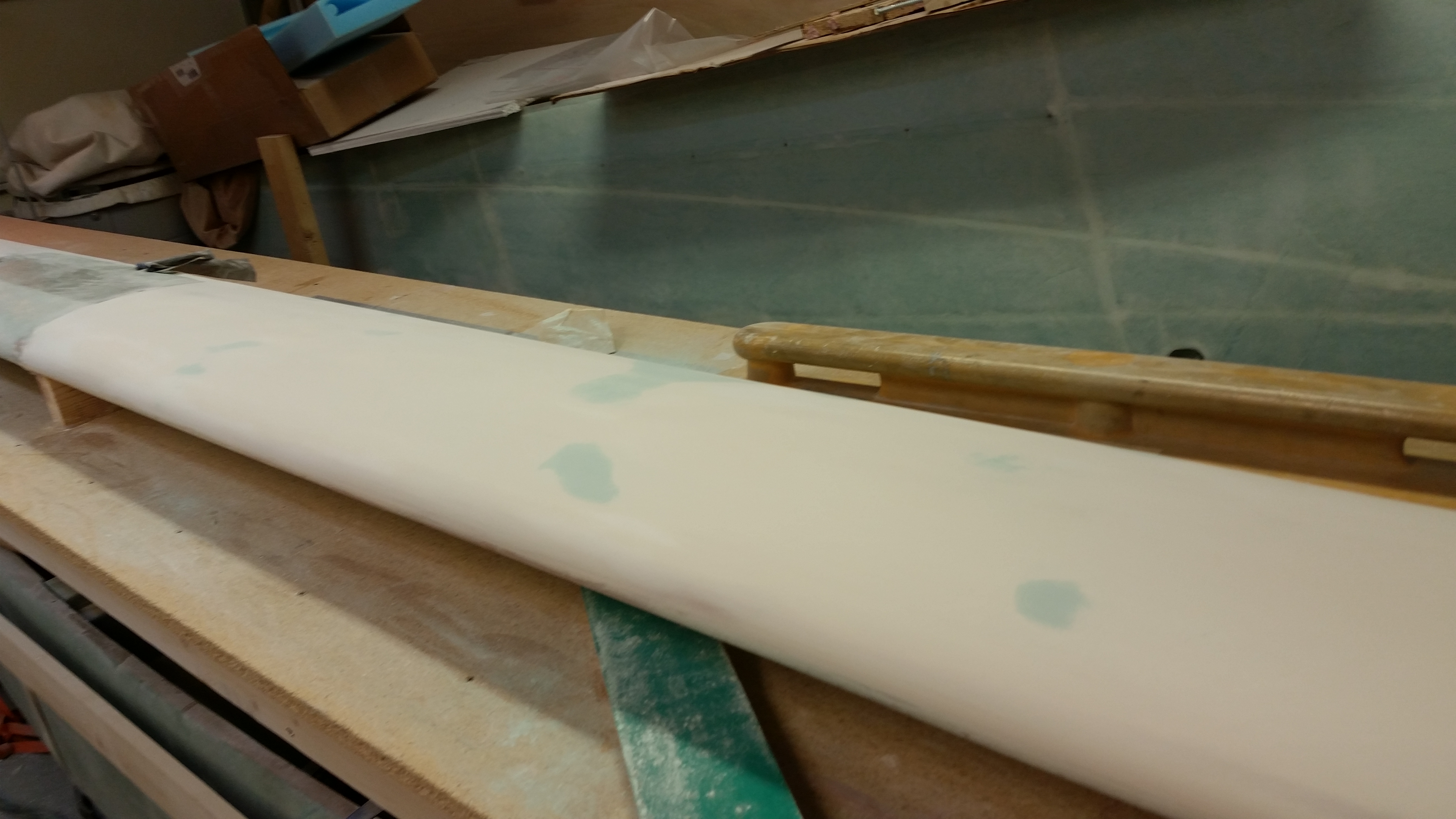
I cleaned the top of the canard off of any sanding dust, and really took my time feeling the surface with my hands for any imperfections. I then went over the entire canard top surface again lightly with the 120 grit long board focusing on any minor issues left to be dealt with.

Final sand left side

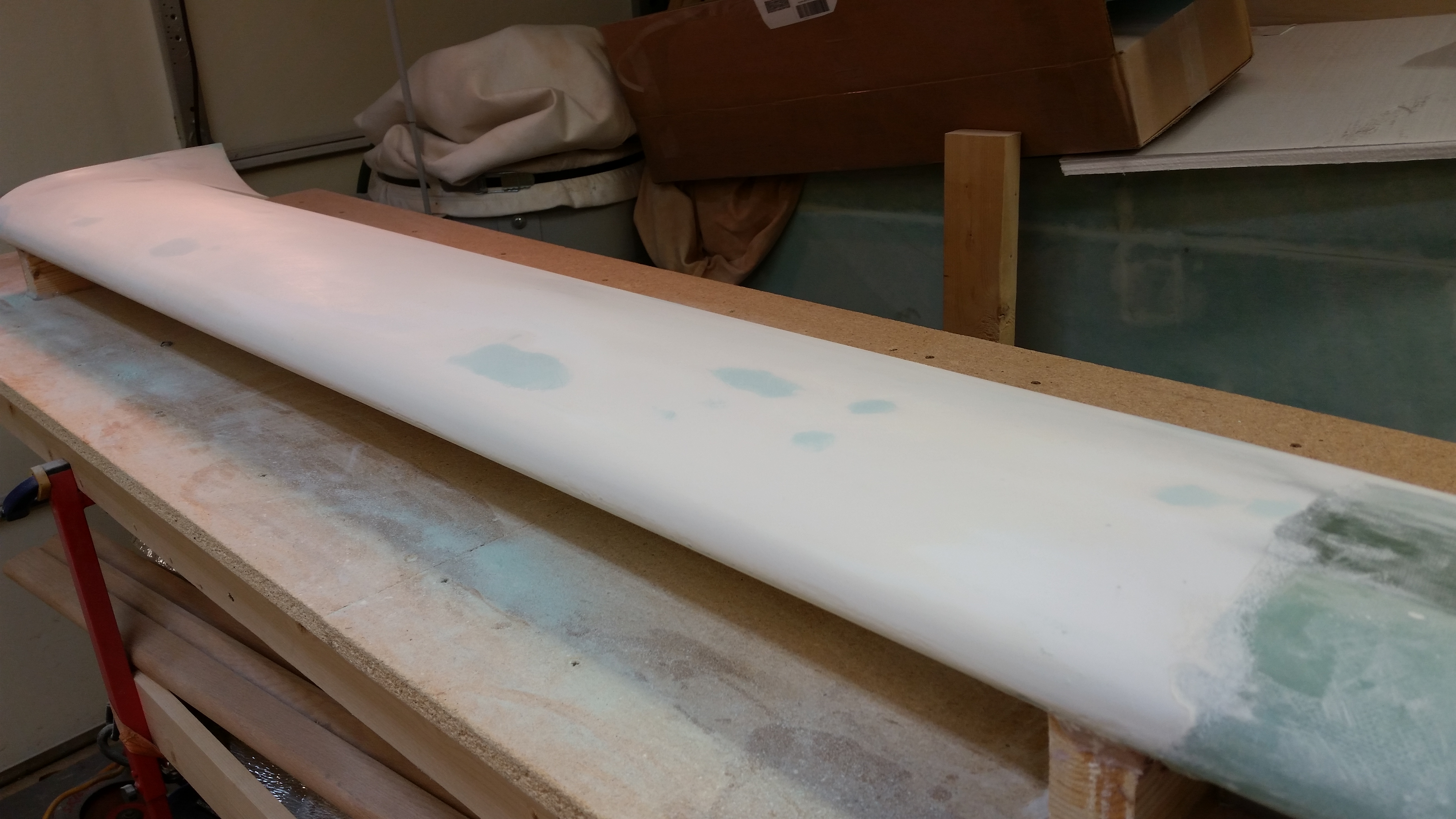
Final sand right side

I then focused on the edge of the right swoosh tip to feather in the two spots I had filled with glazing putty.

Right swoosh tip sanded

I’m very satisfied with the final fill of the canard top surface.  Although I’m sure a few minor elevation differences will rear their ugly heads during future final sandings and surface prep, the top of the canard is ready for a final coat or two of primer, some final wet sanding, and then paint.  Obviously, as per above, I just have to figure out what primer & paint that will be!

Now that I’ve got my electrical component curiosity satisfied for the internal nose configuration, I was finally able to focus on getting the fuselage pulled out from under the canard build table and mounted onto the fuselage dolly.

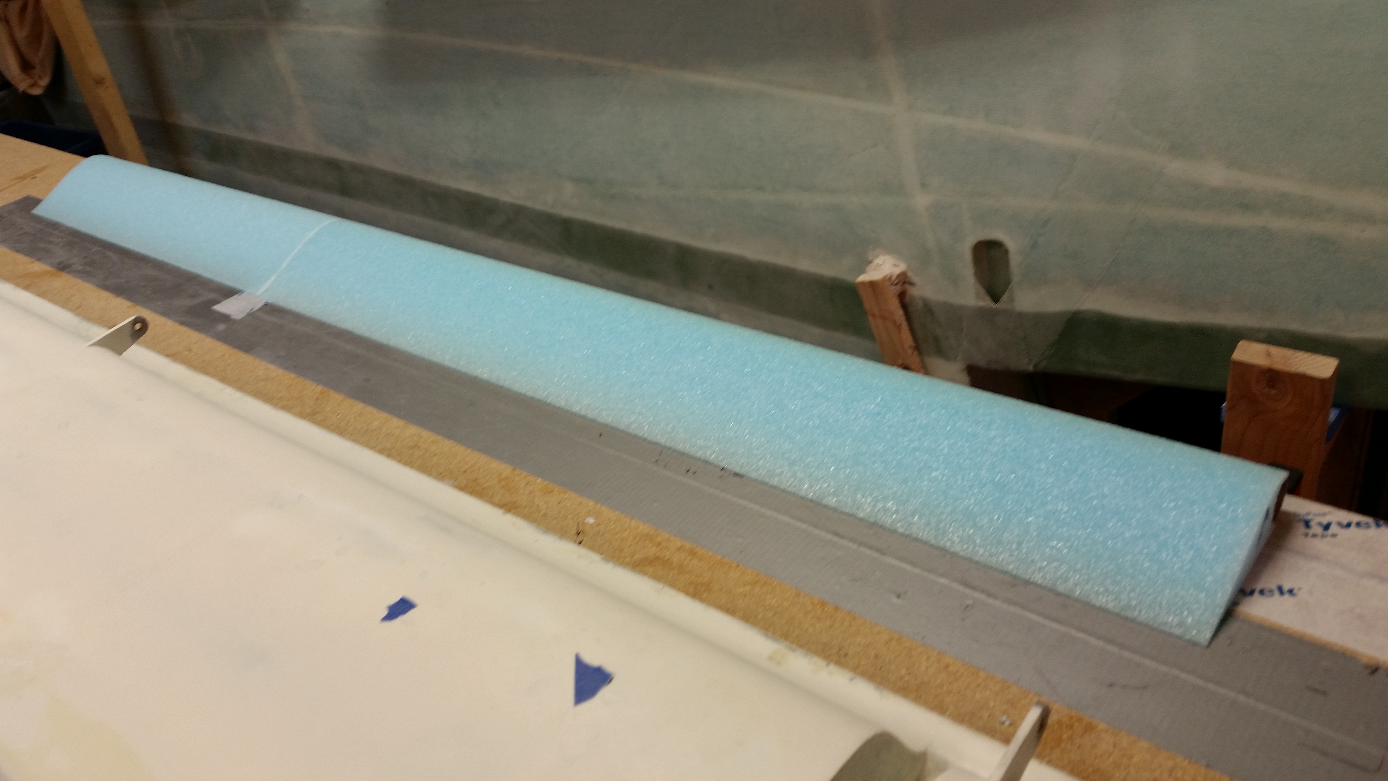
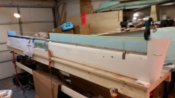
Fuselage on dolly!

Over the next few days I’ll be focusing primarily on the bottom of the canard: getting all the divots filled and sanding it for final paint prep.  I’ll also be remounting the elevators, checking alignment, and rebuilding the left elevator.  Finally, I’ll finalize the mounting of the fuselage on the dolly, reconfigure the shop to allow for room to work on the fuselage, and get moving on the nose build.