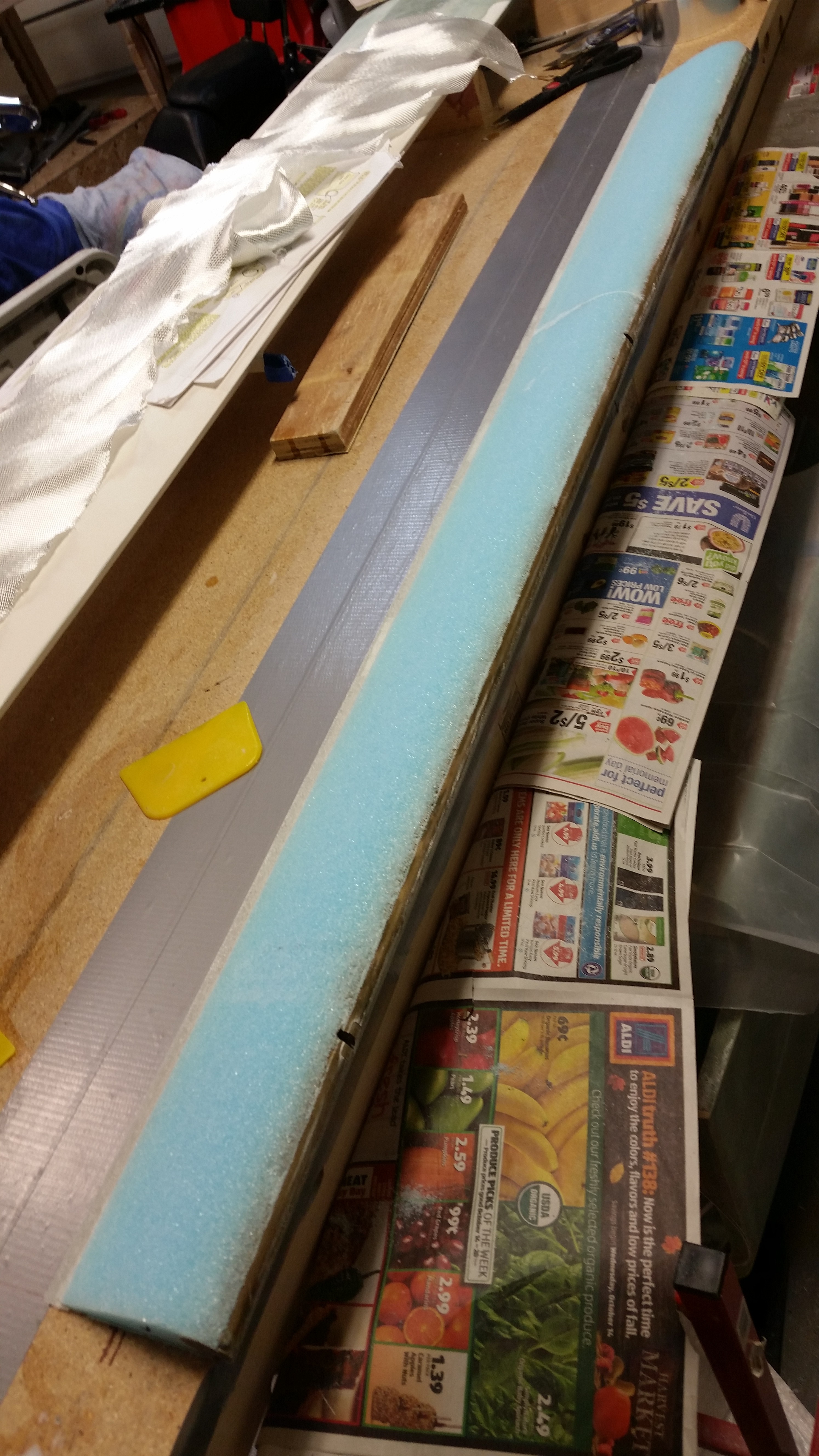
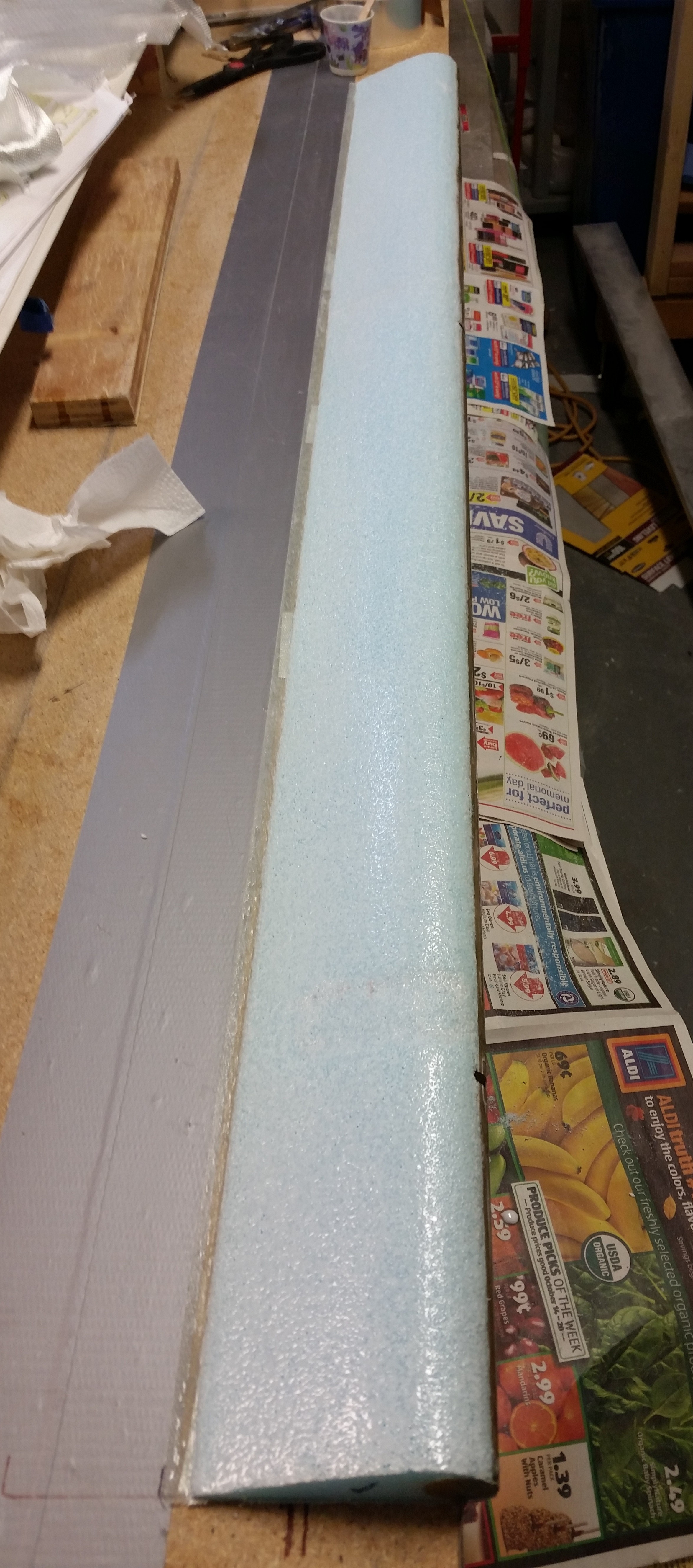
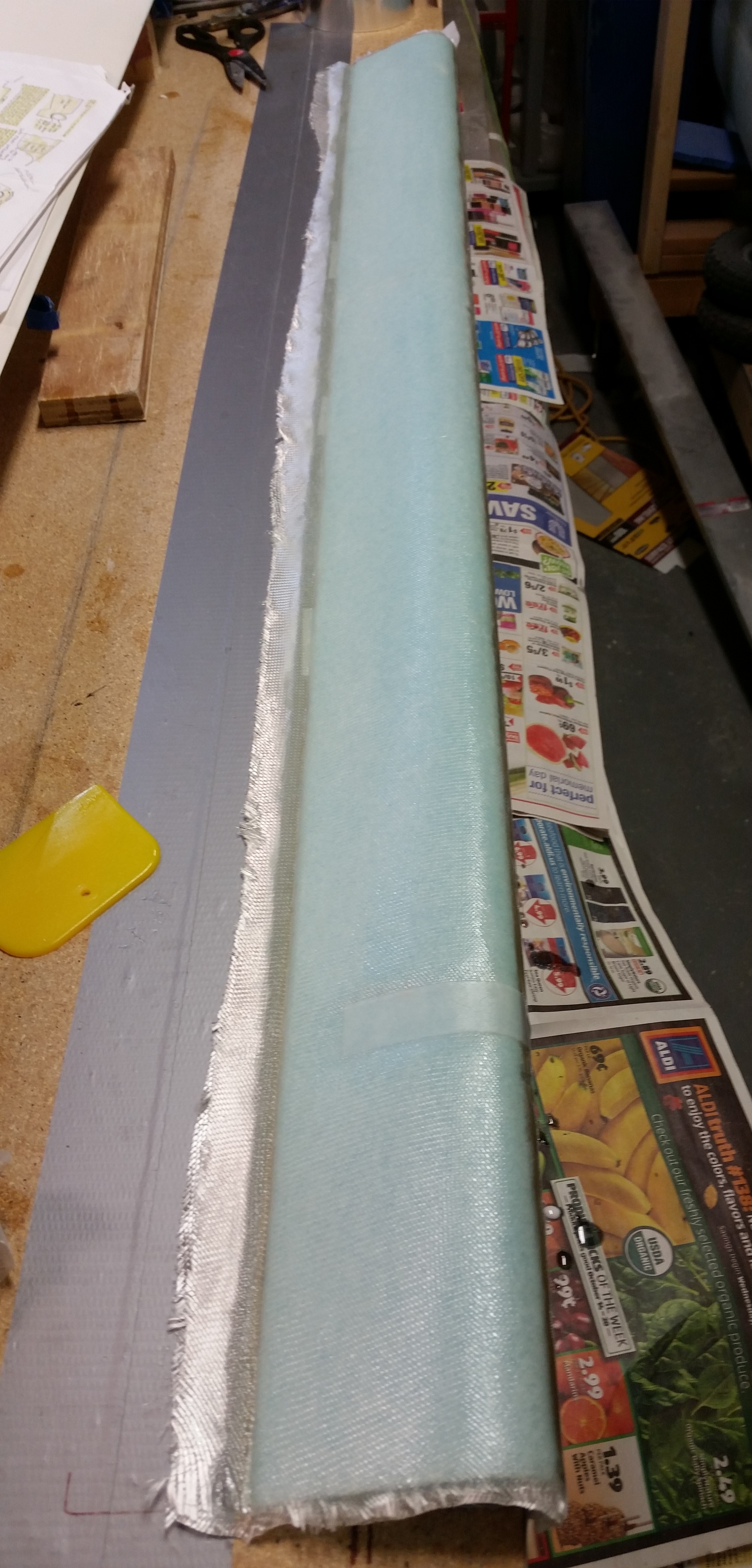
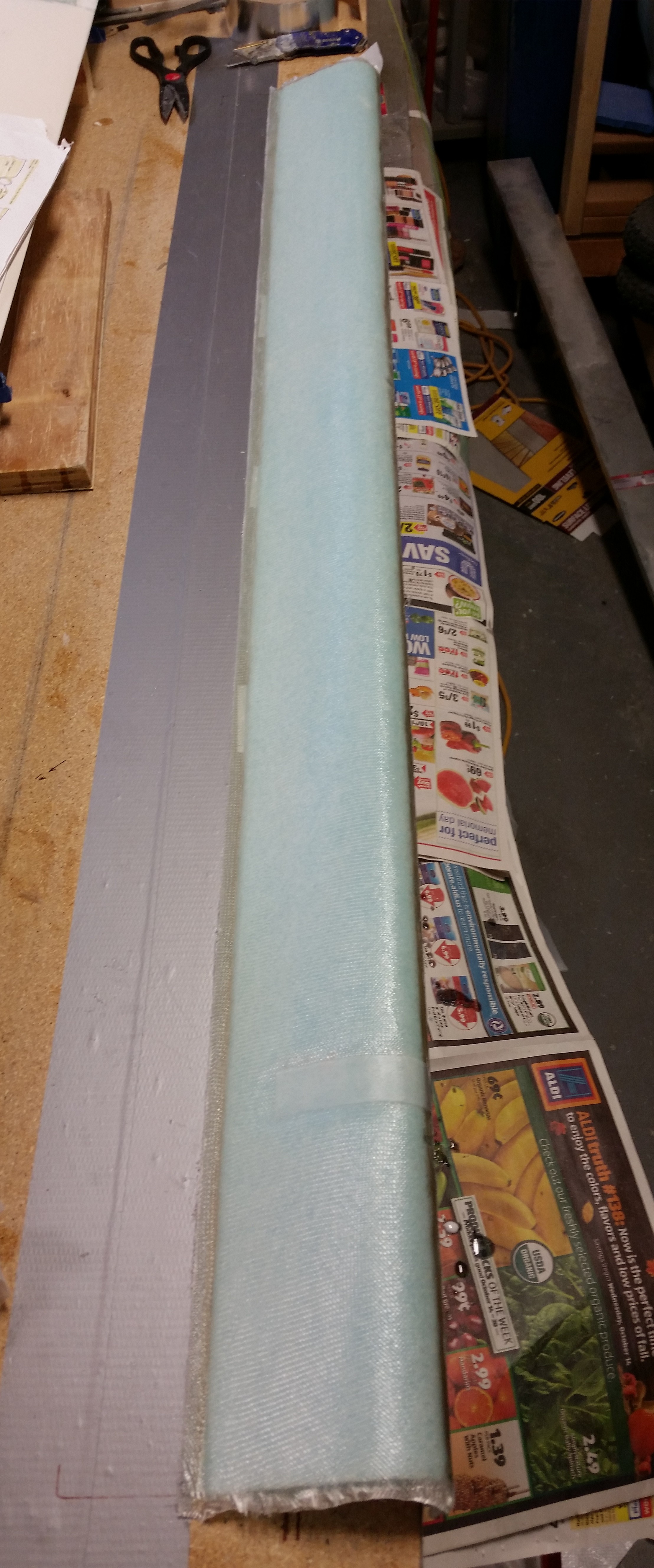
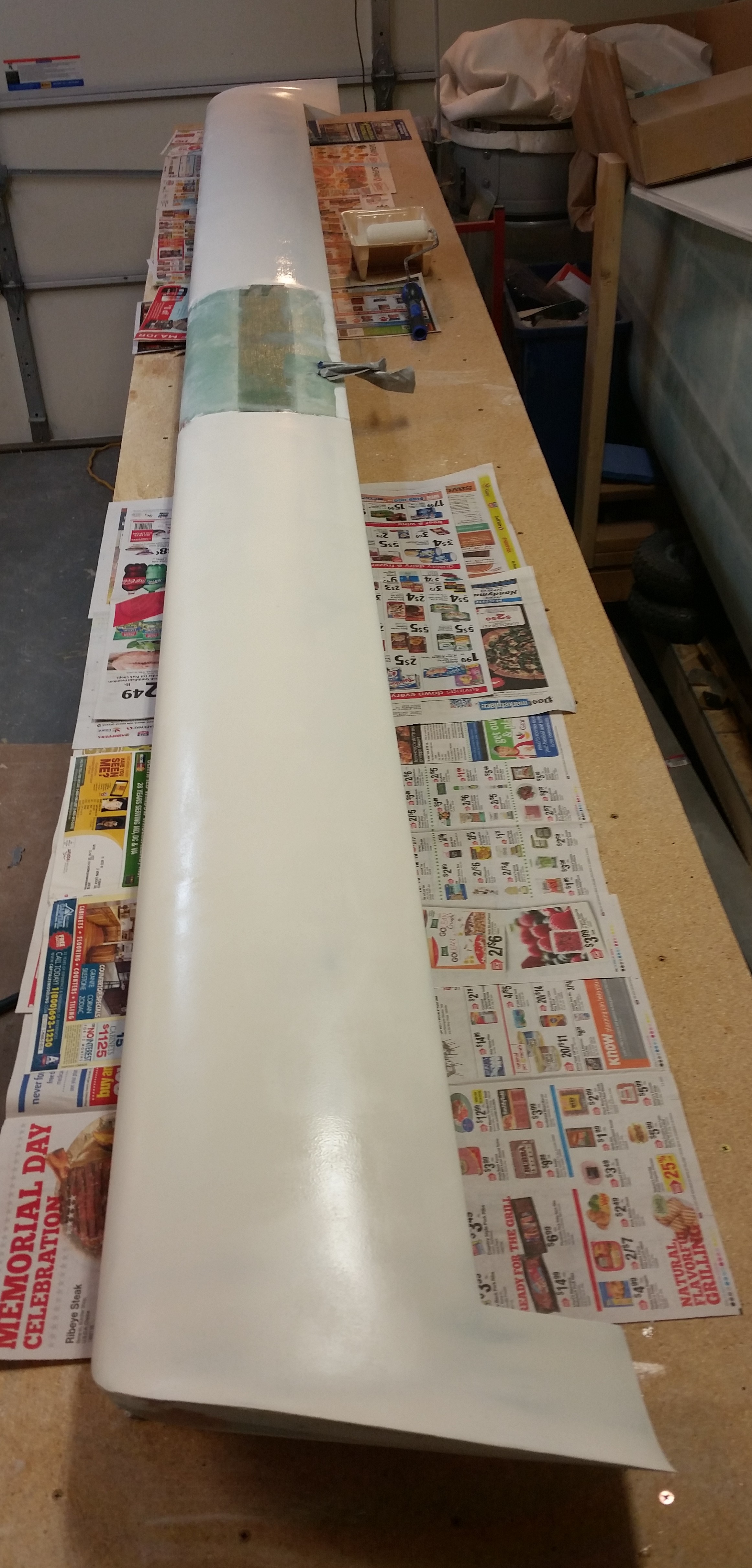
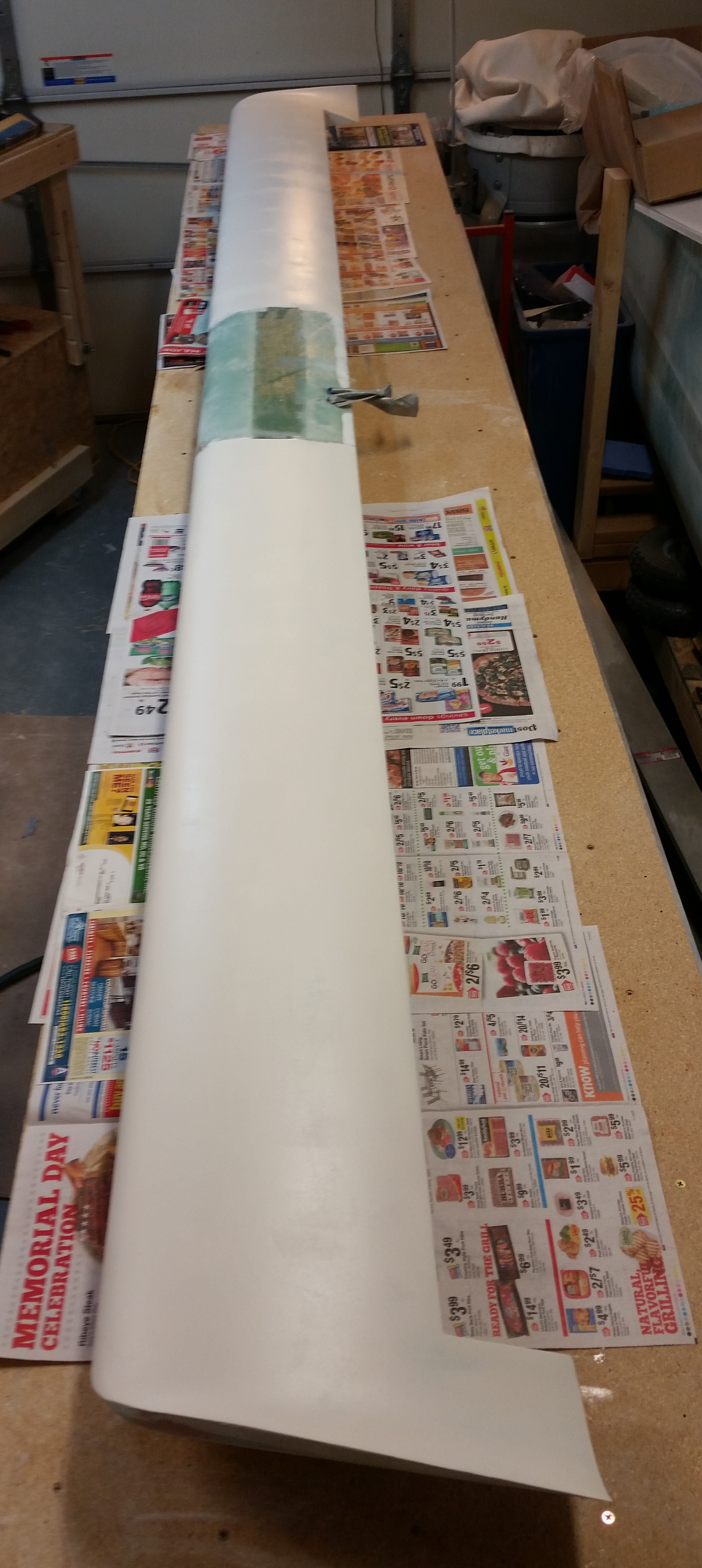
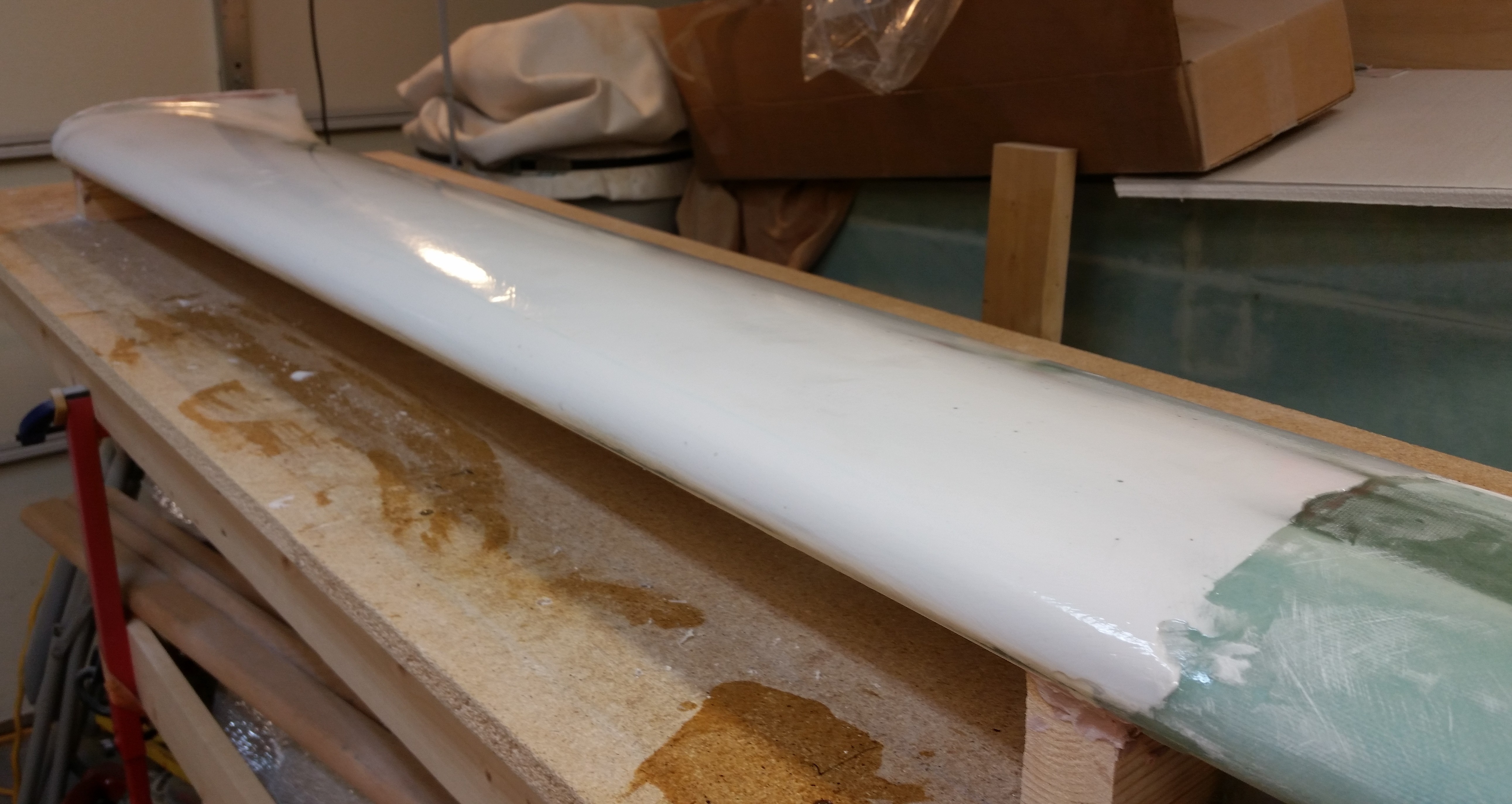
Chapter 11 – Elevator redo done!

For the right elevator at least.

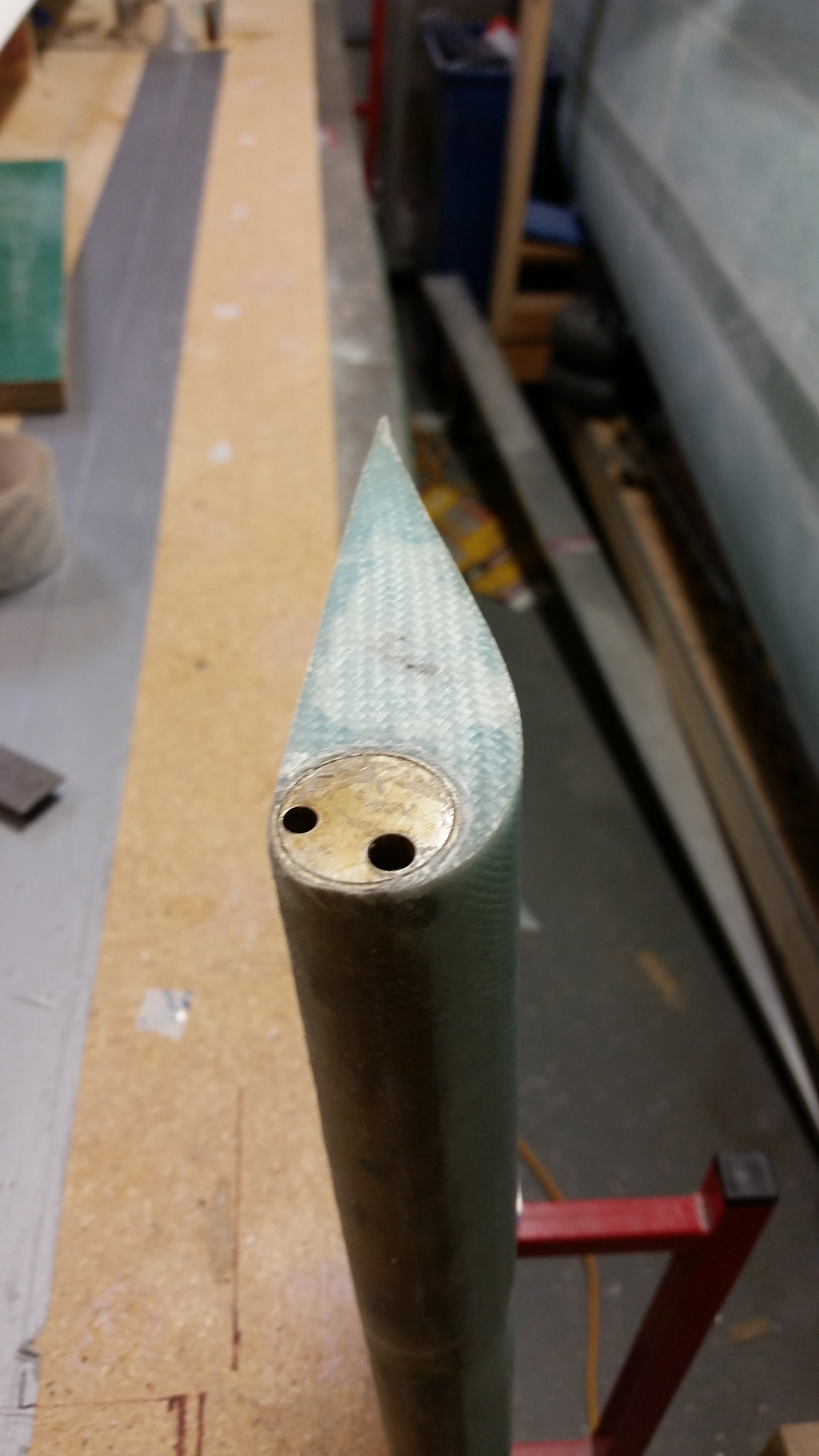
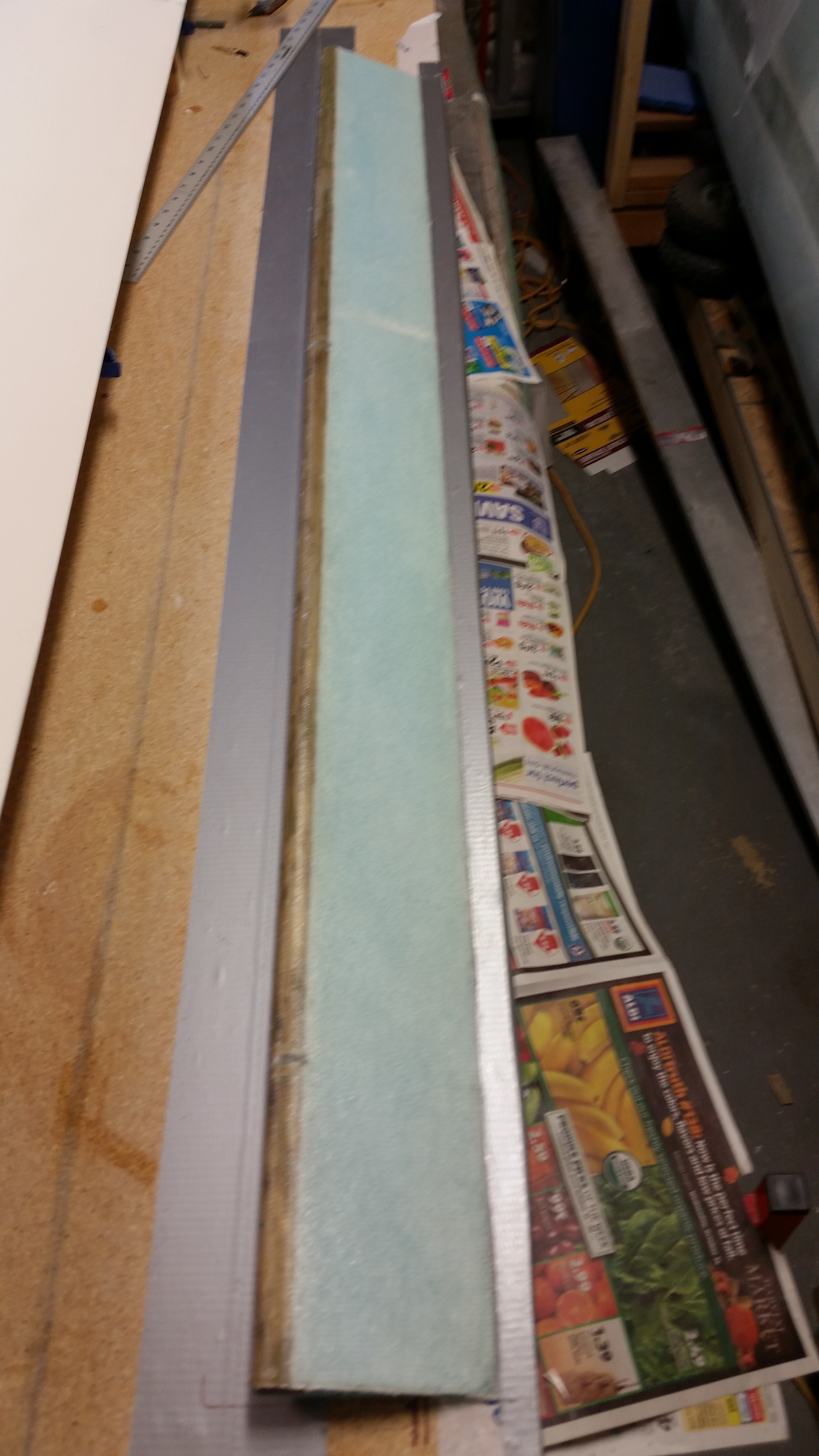
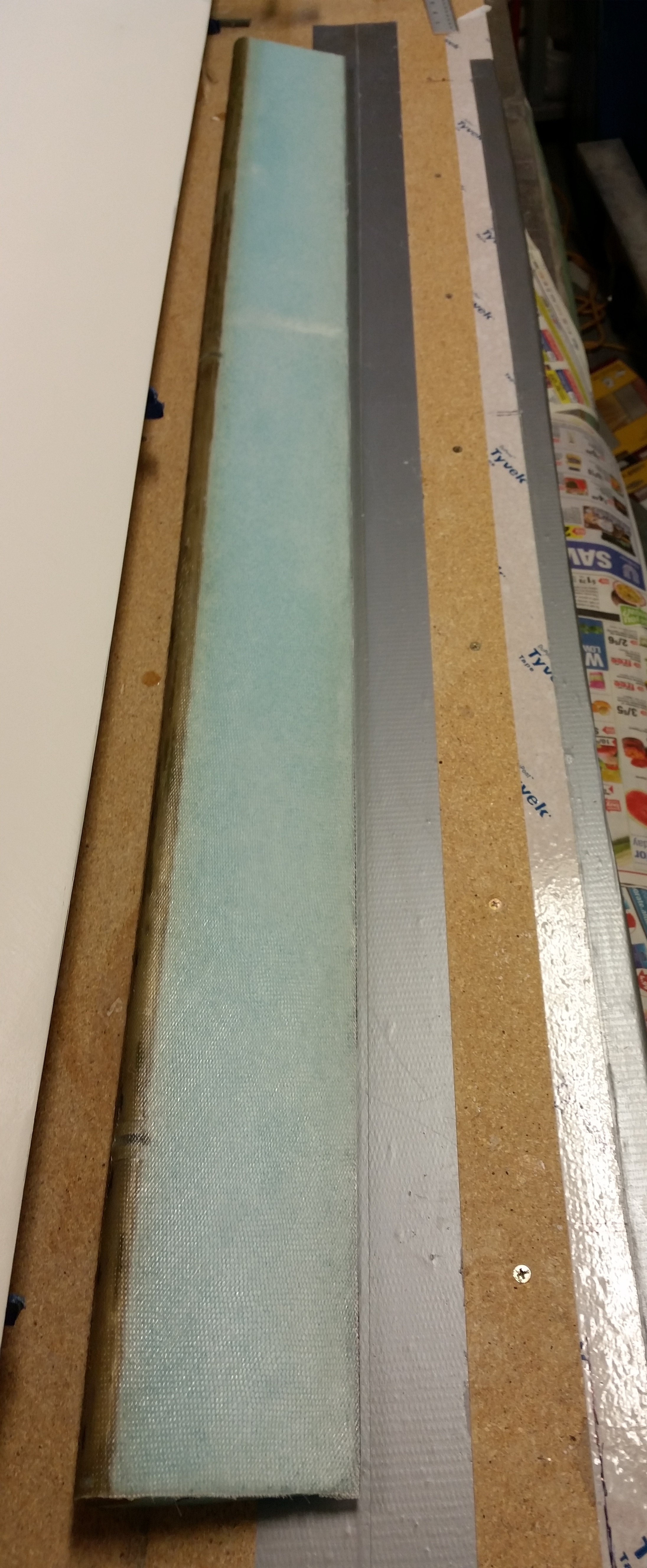
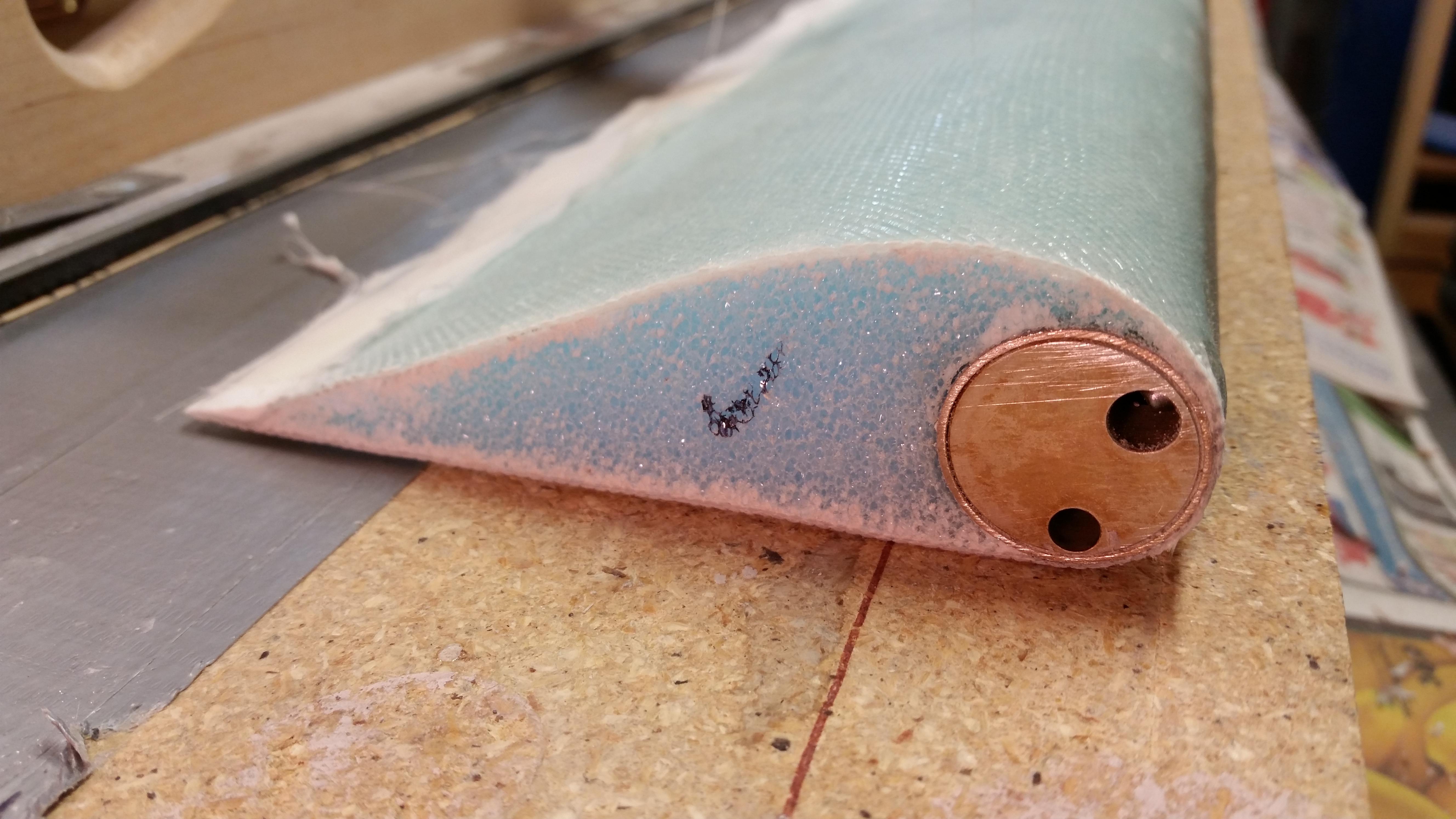
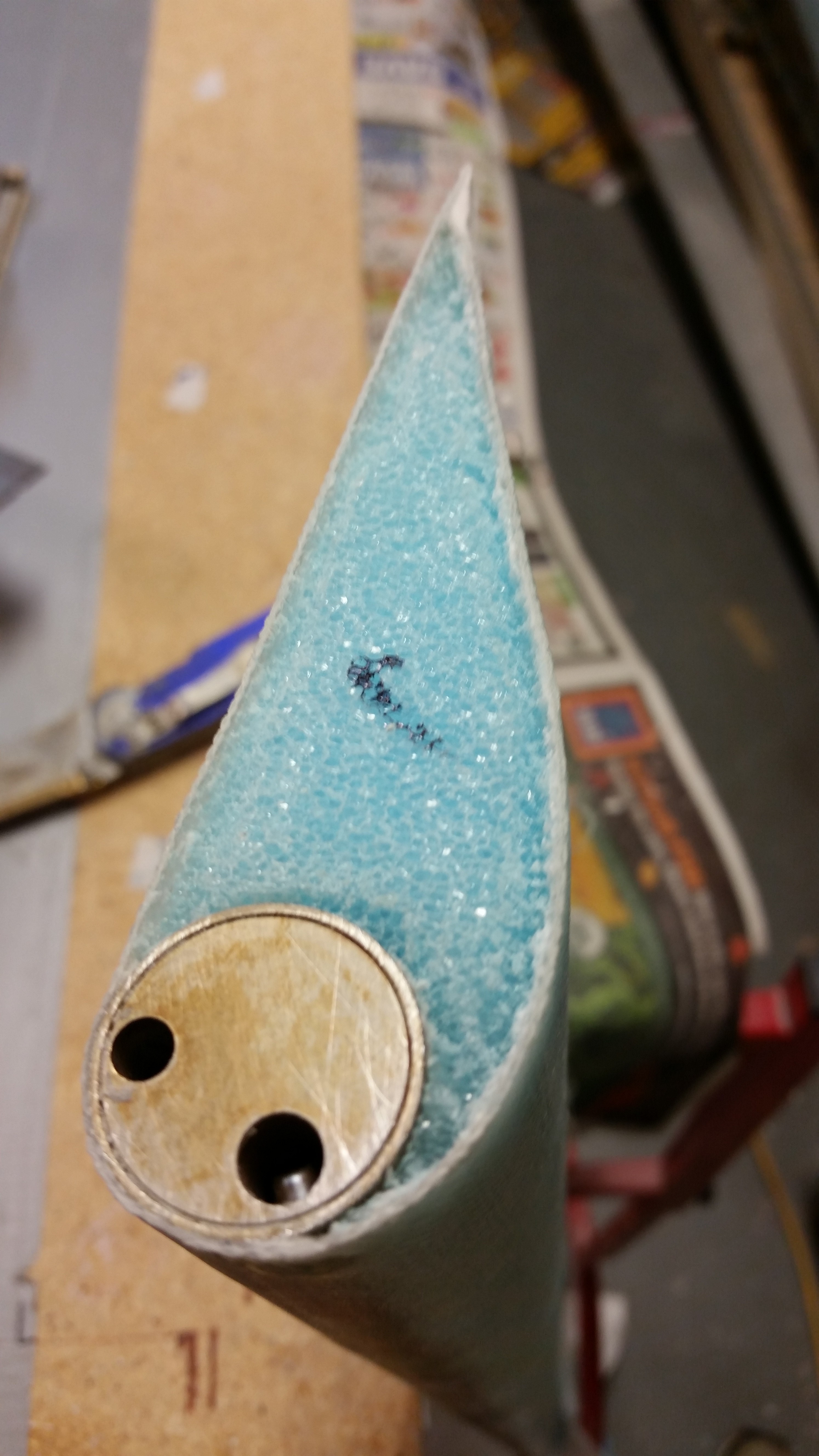
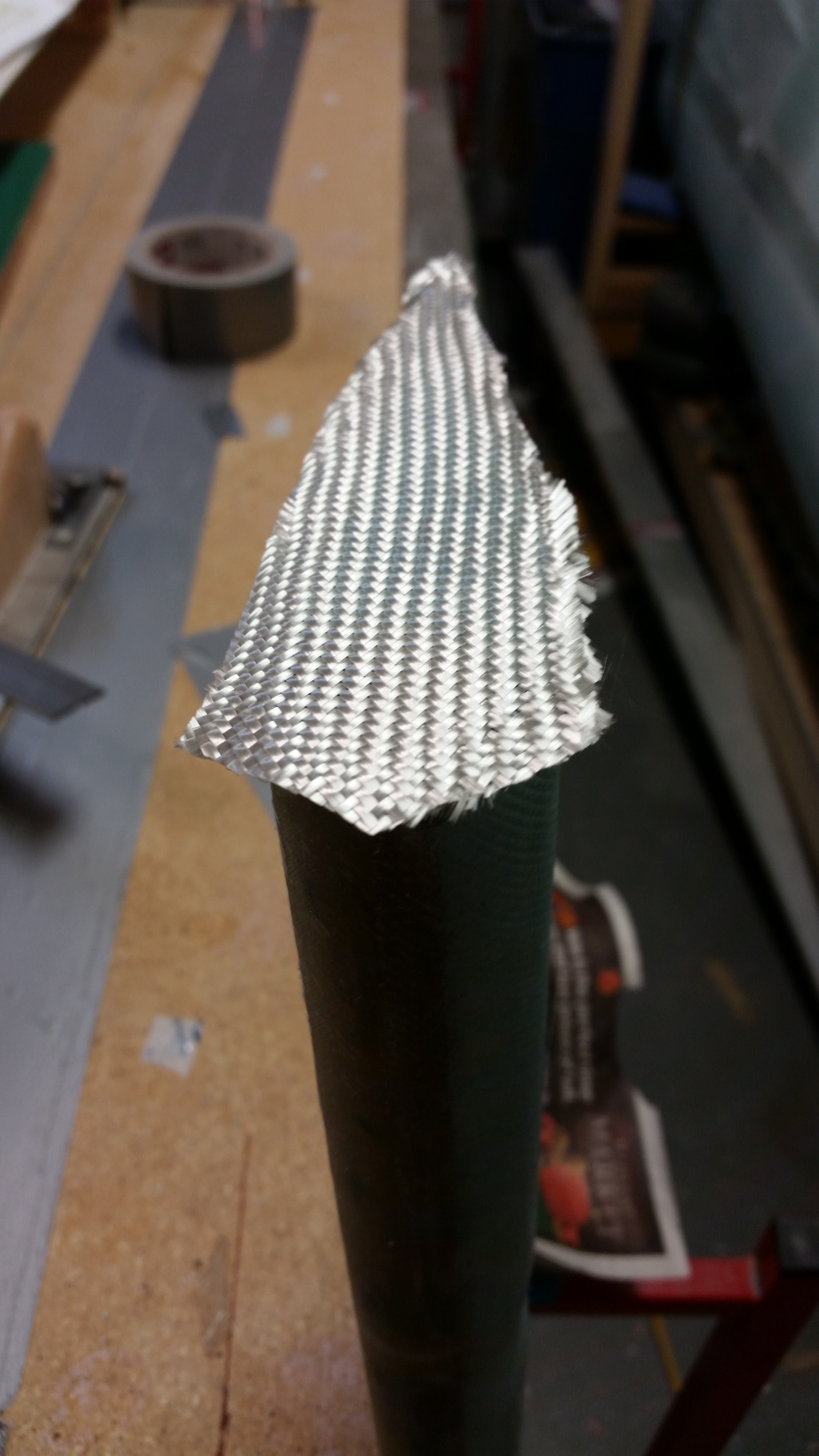
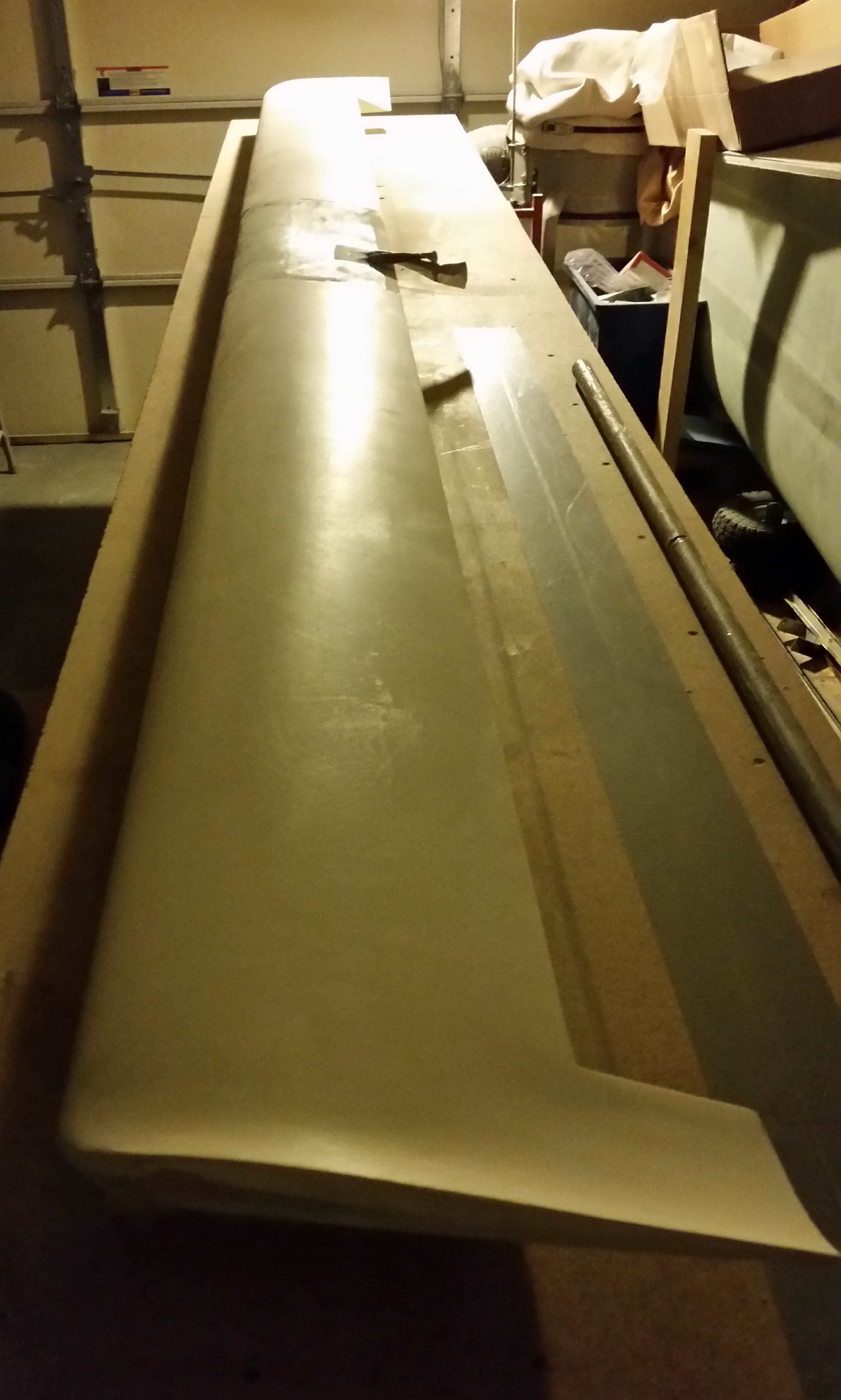
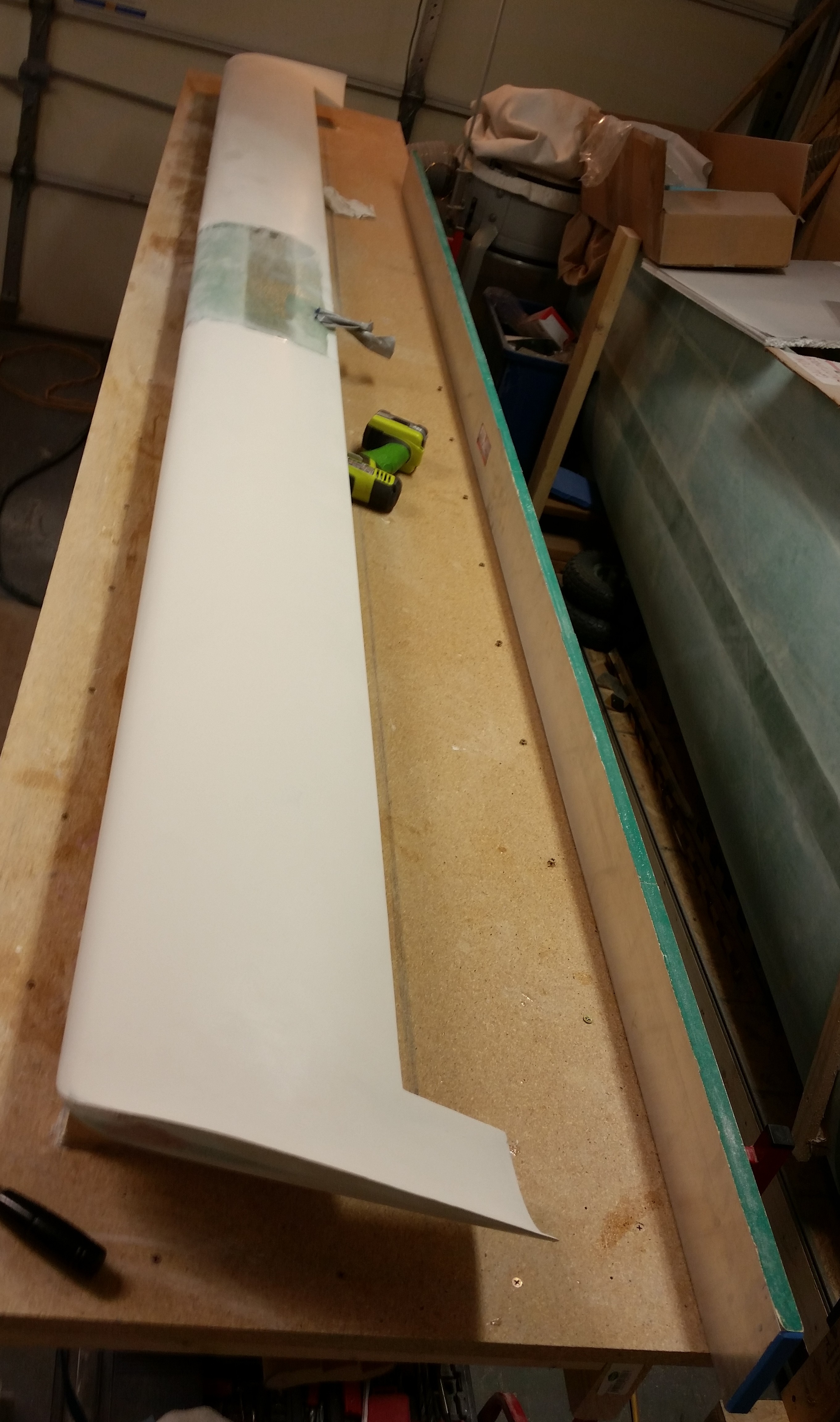
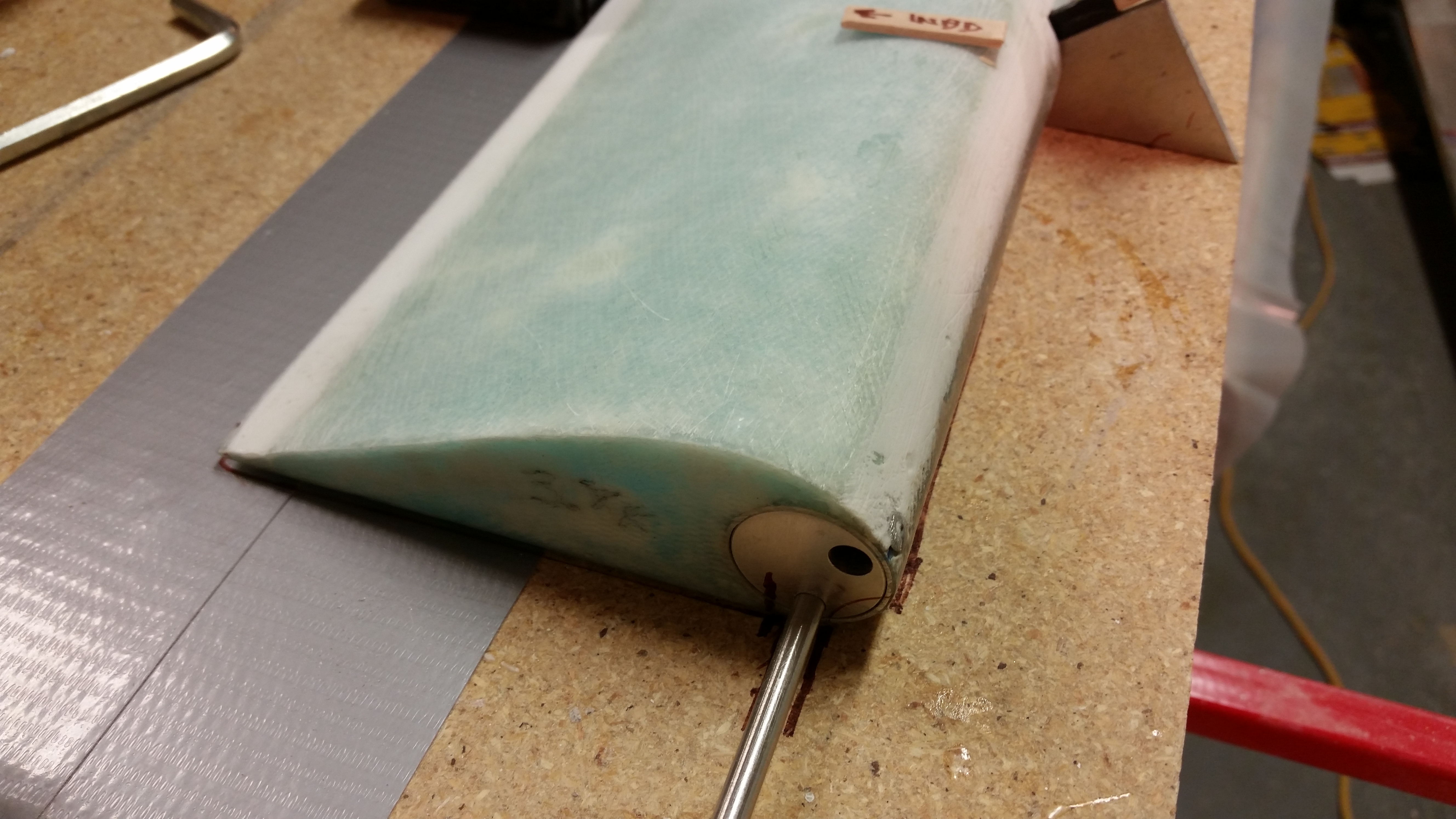
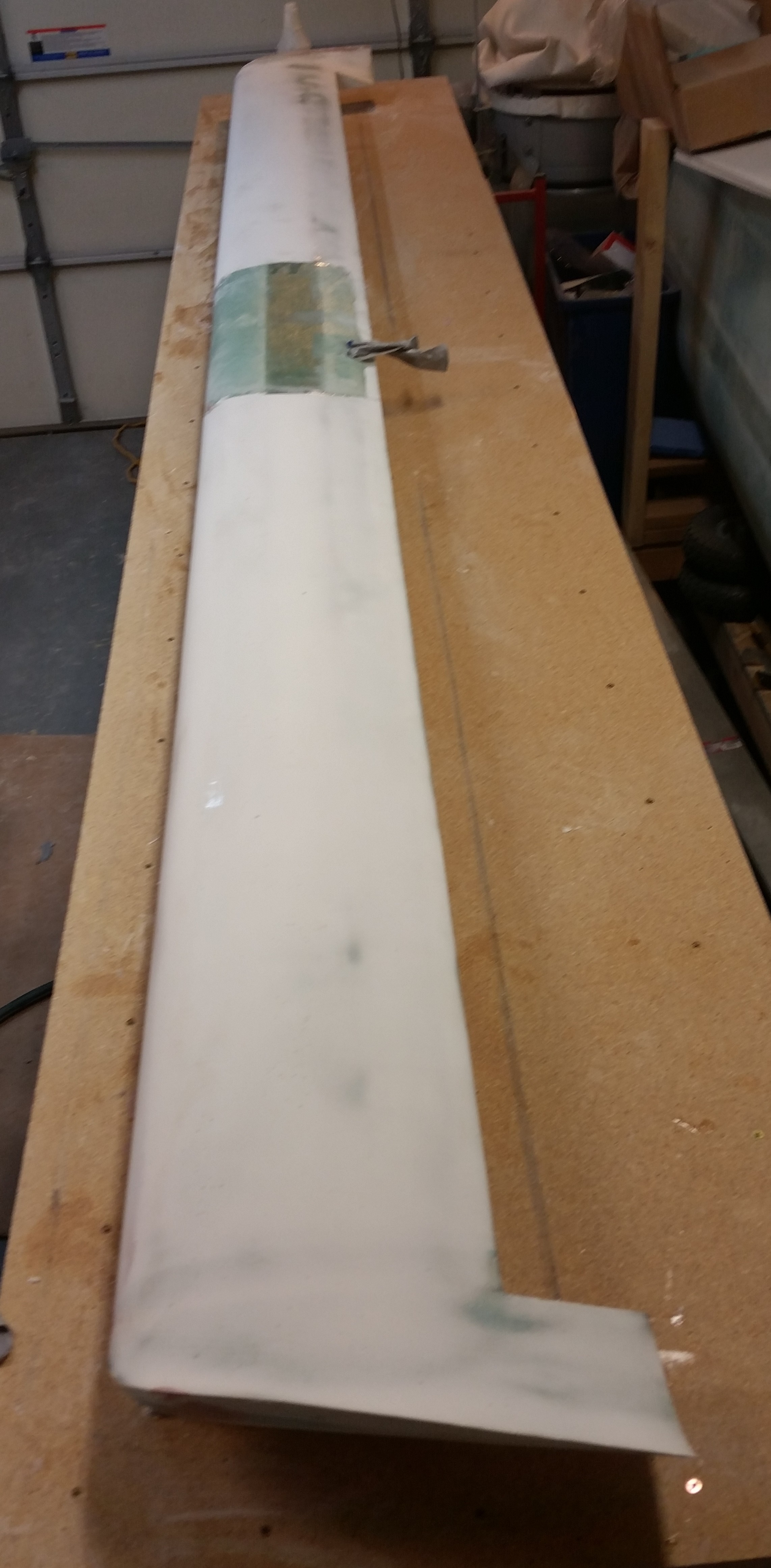
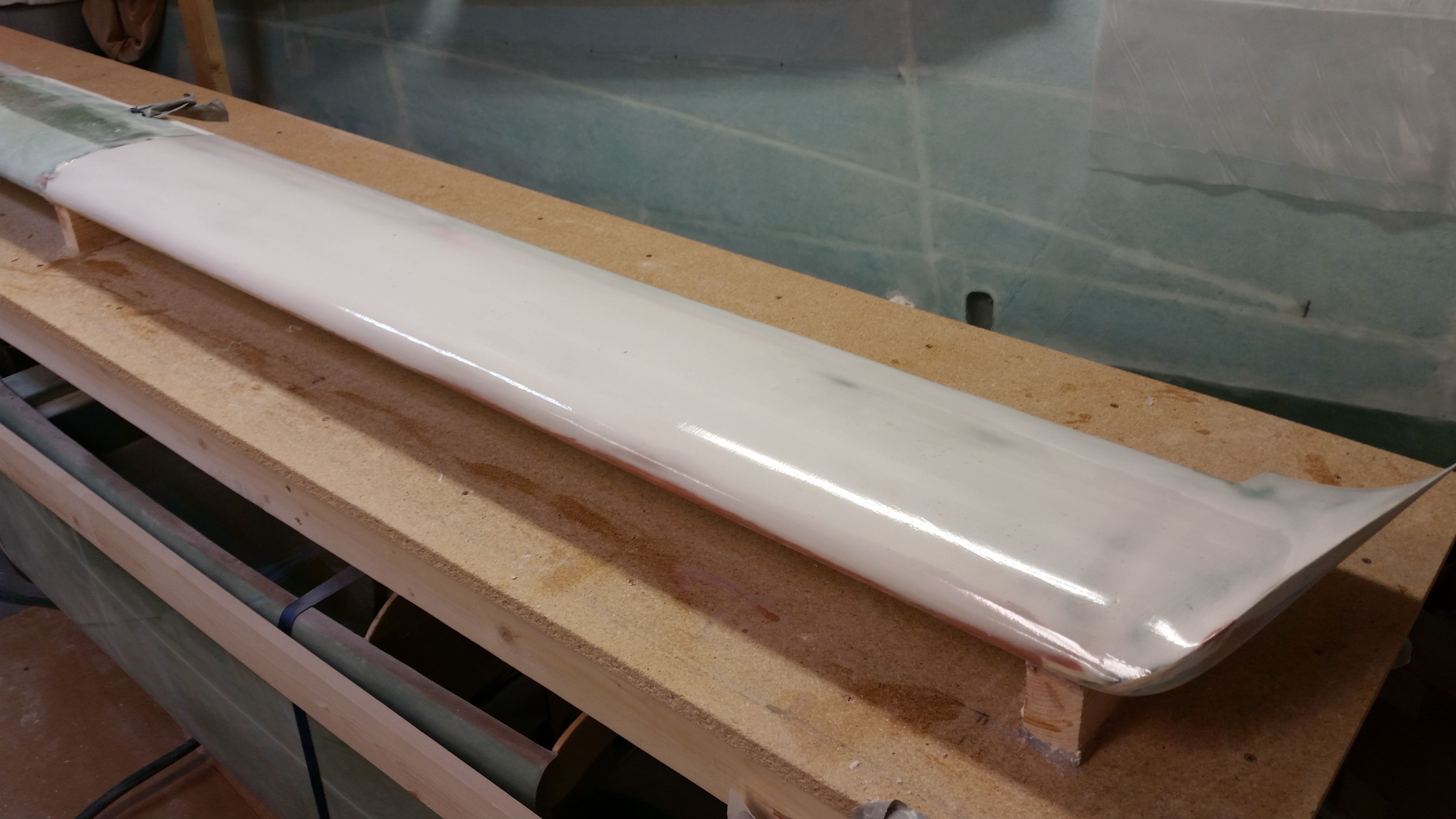
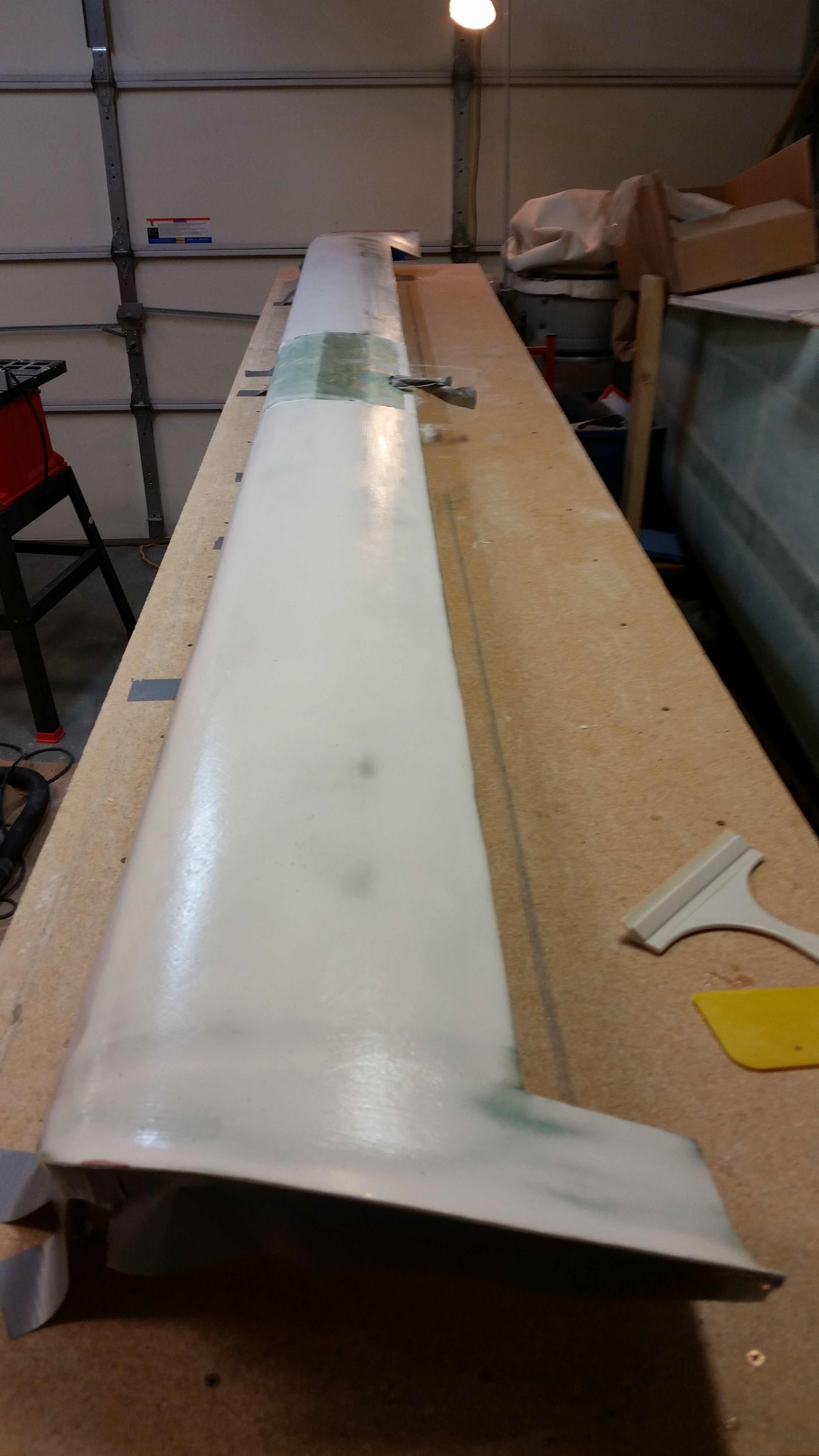
I started off today by trimming the elevator 1-ply BID glass that I laid up last night.  I never made it back down to razor trim, so thank goodness it’s only one ply.  I then sanded the edges flush with the surrounding top & bottom skins.  I also had to cut out the glass over the NC-6 insert, and while doing so thought I should have stepped out of my paradigm and just glassed over all of it.  Oh, well, a few more minutes and I had what you see below.

Outboard elevator end

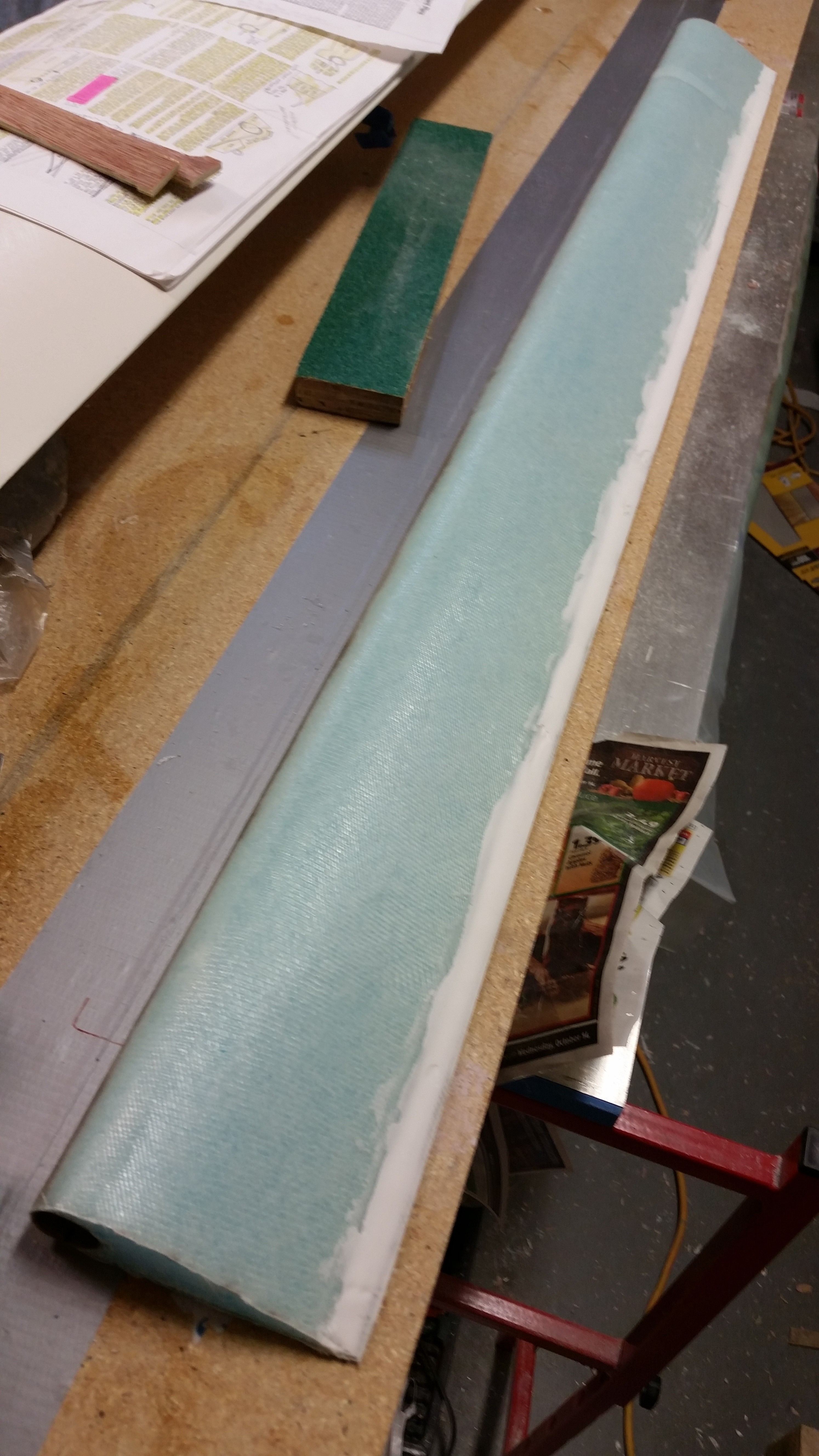
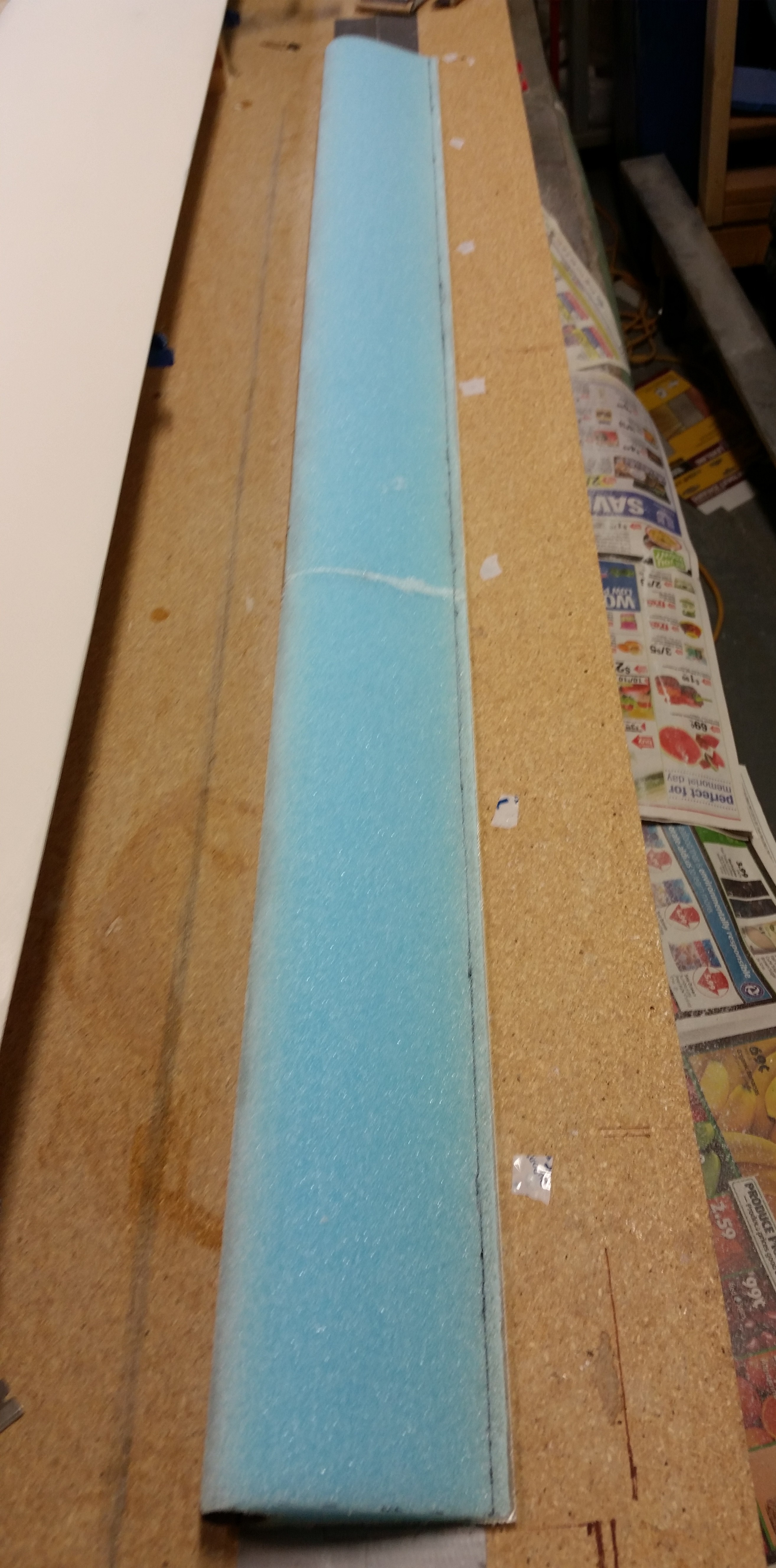
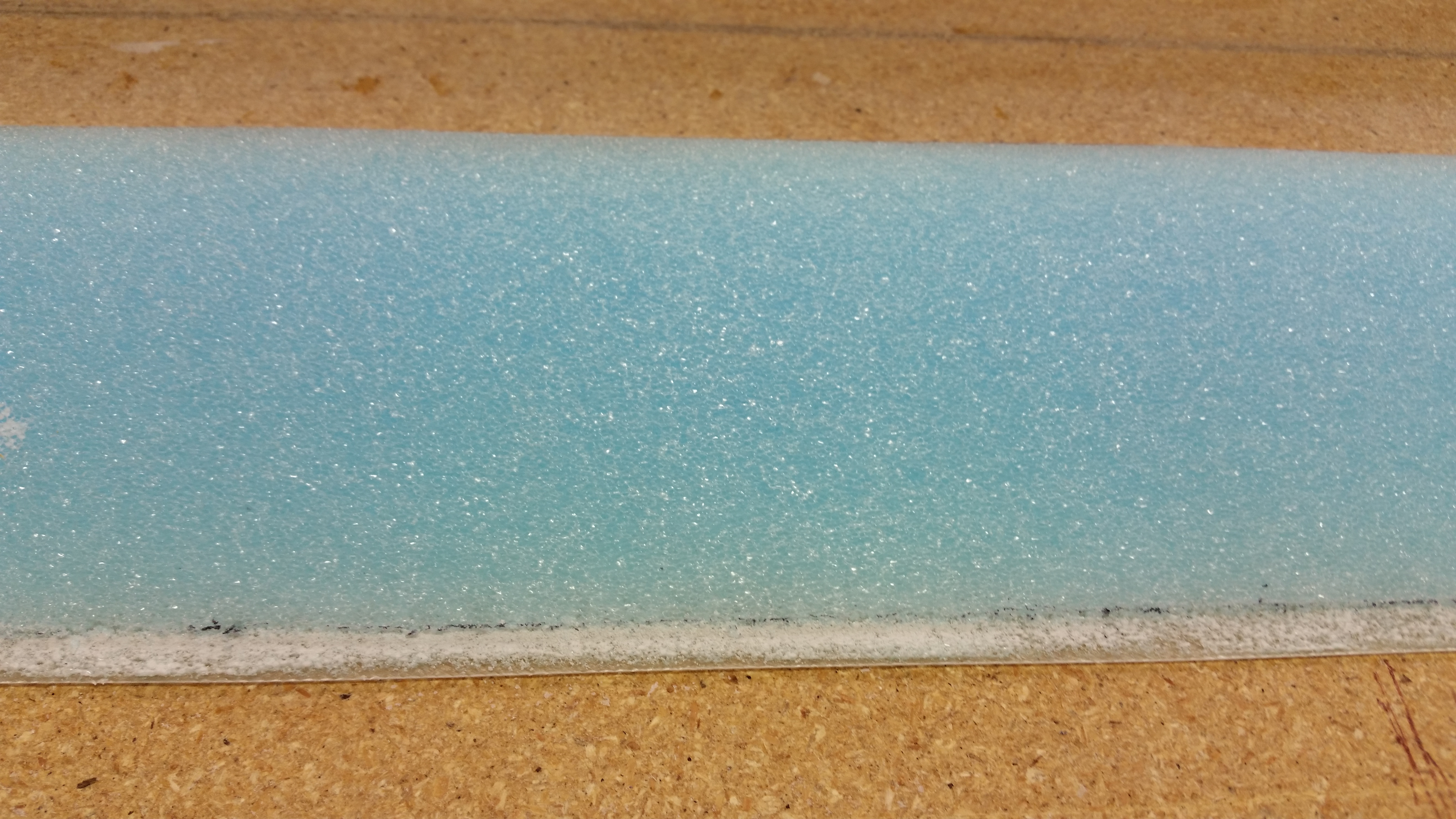
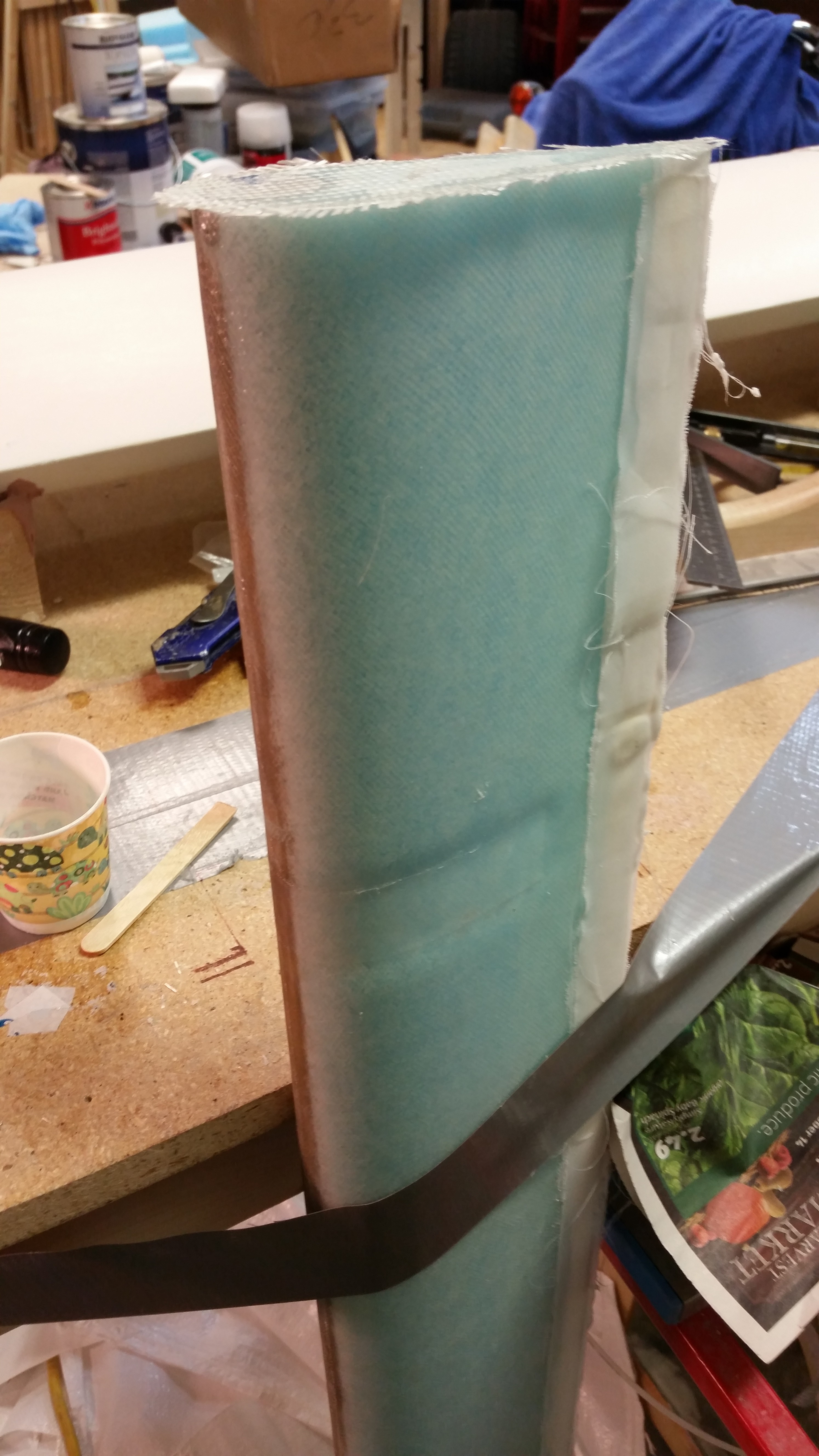
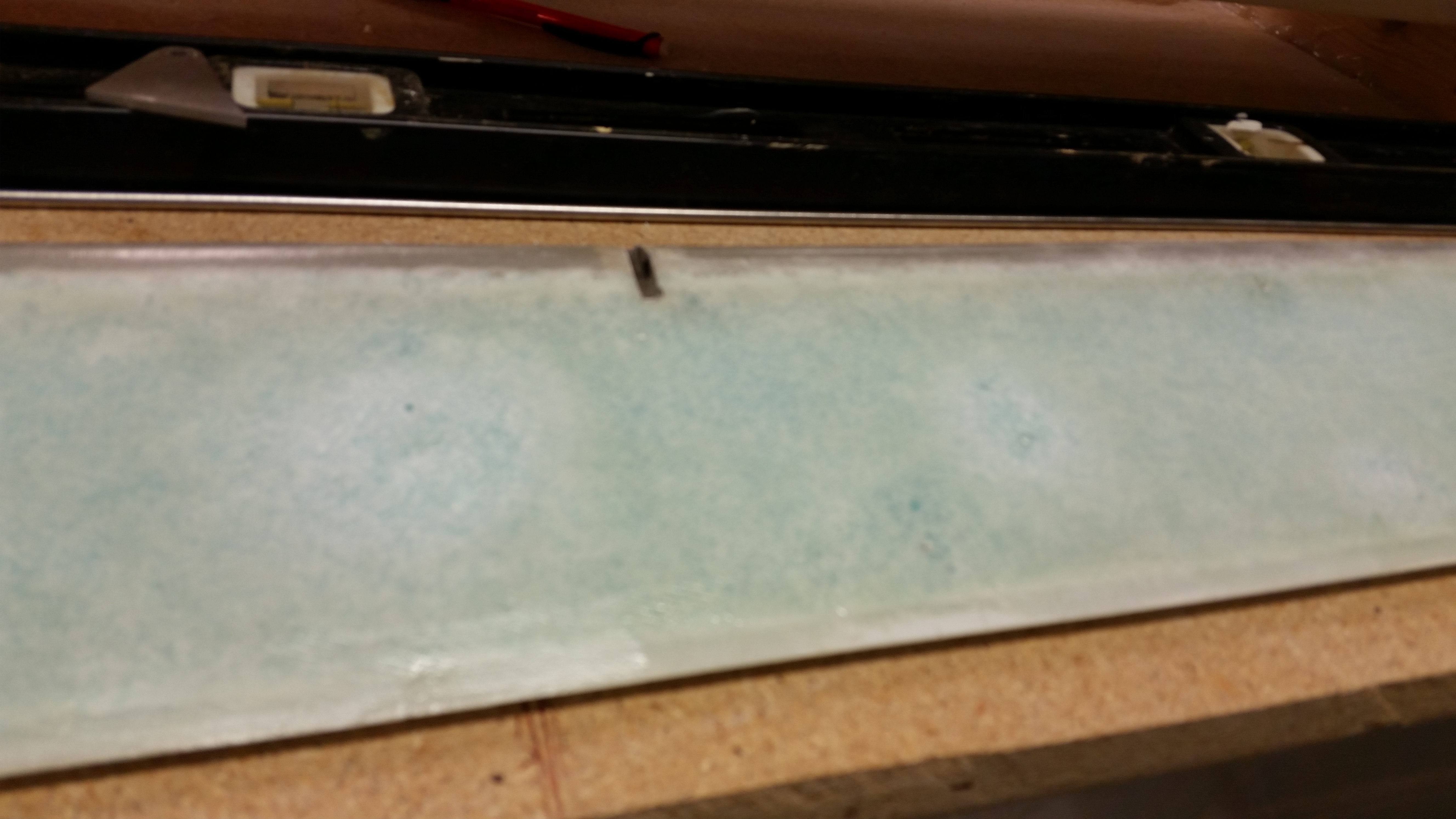
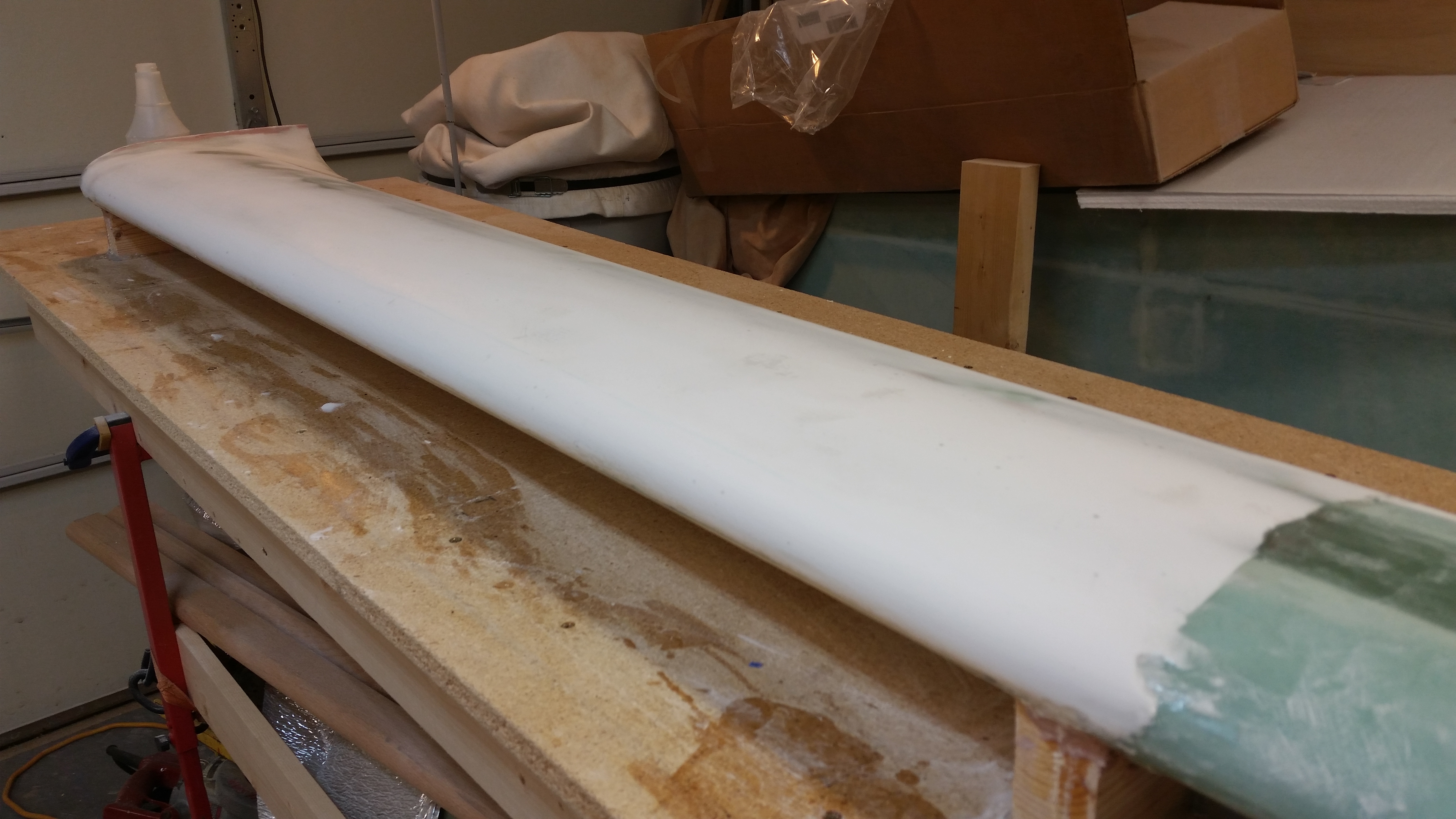
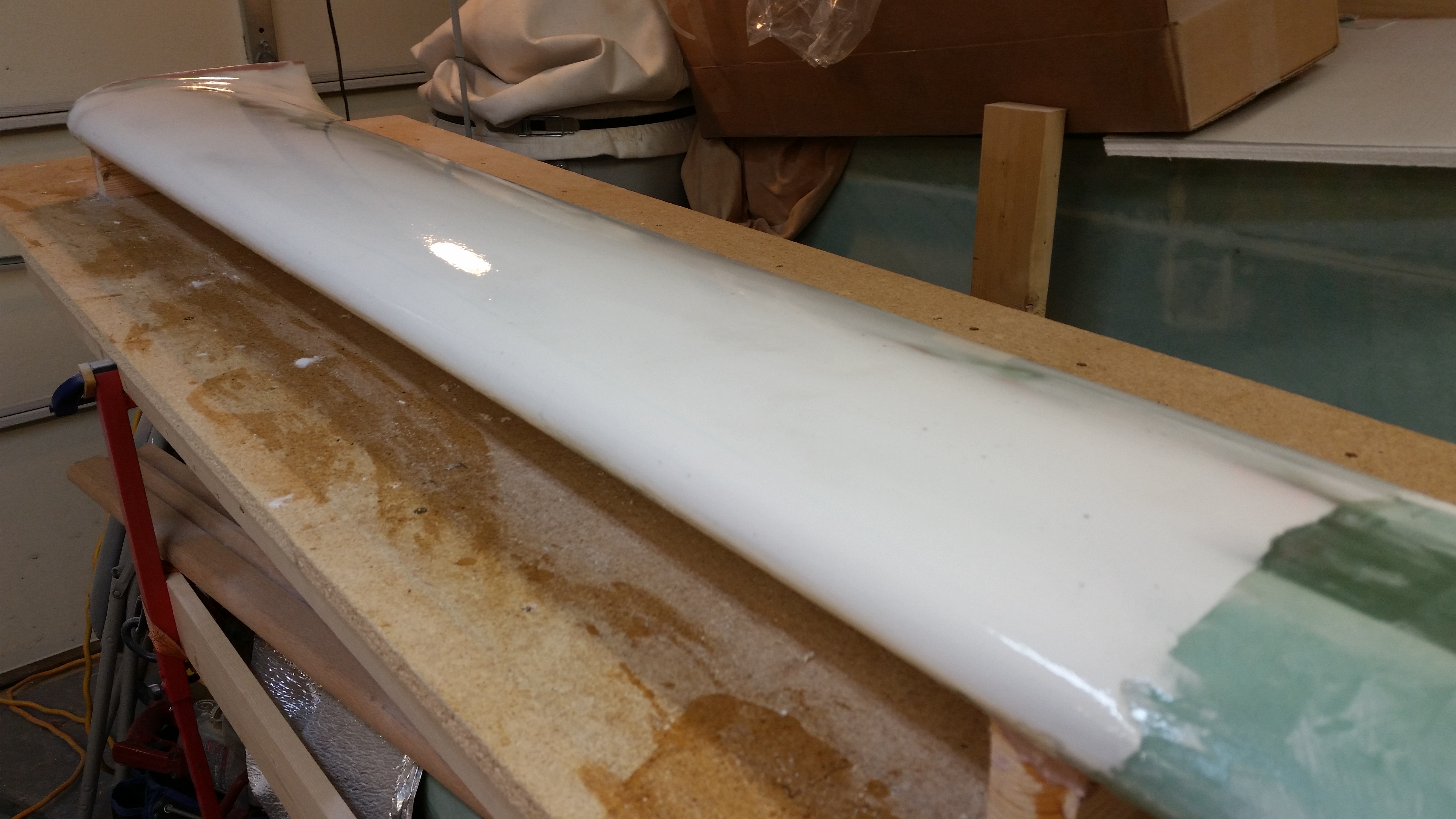
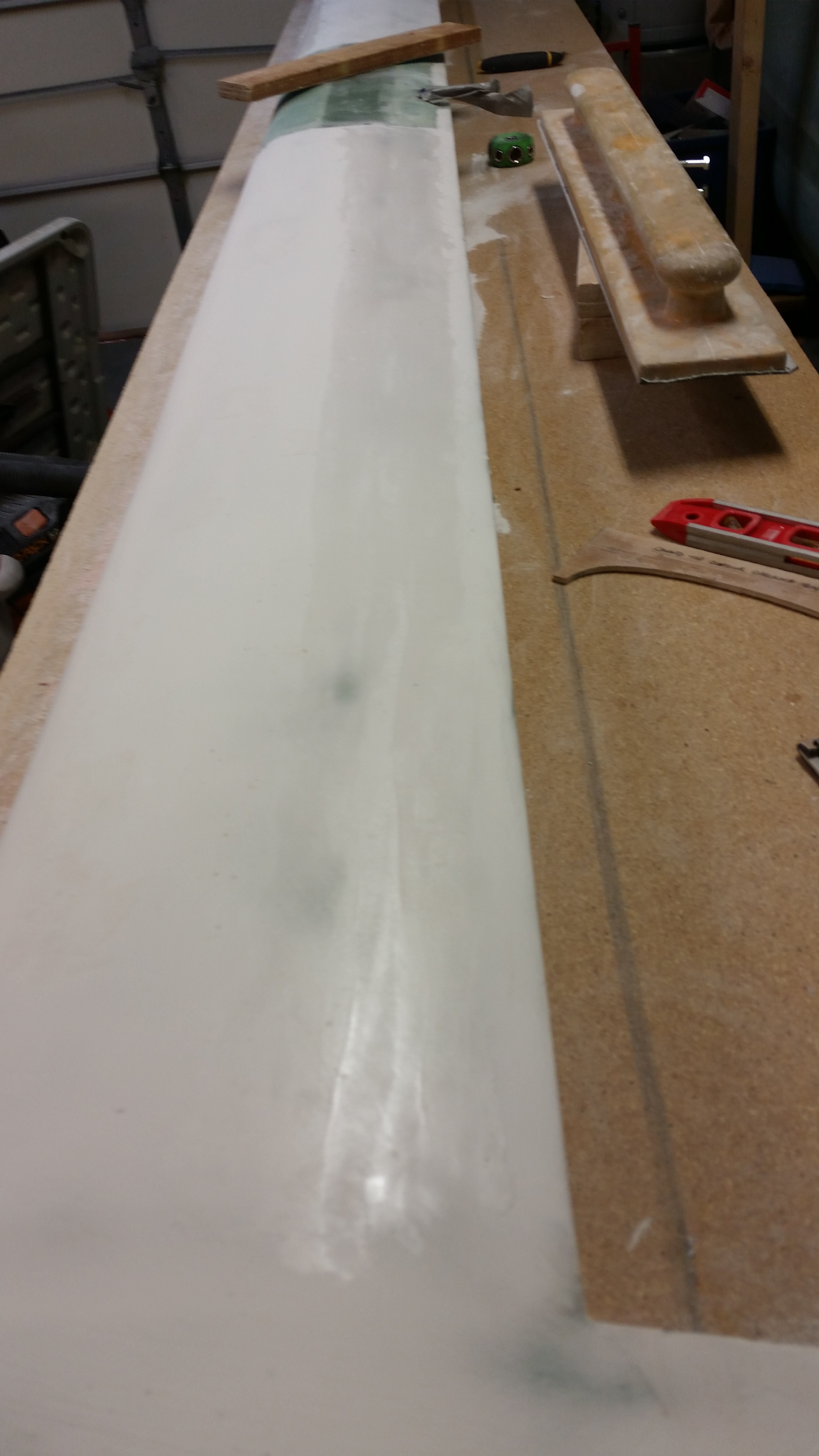
I then turned my sights first on sanding the rough spots of the LE, and I then pulled the peel ply and sanded the TE.

Sanded TE

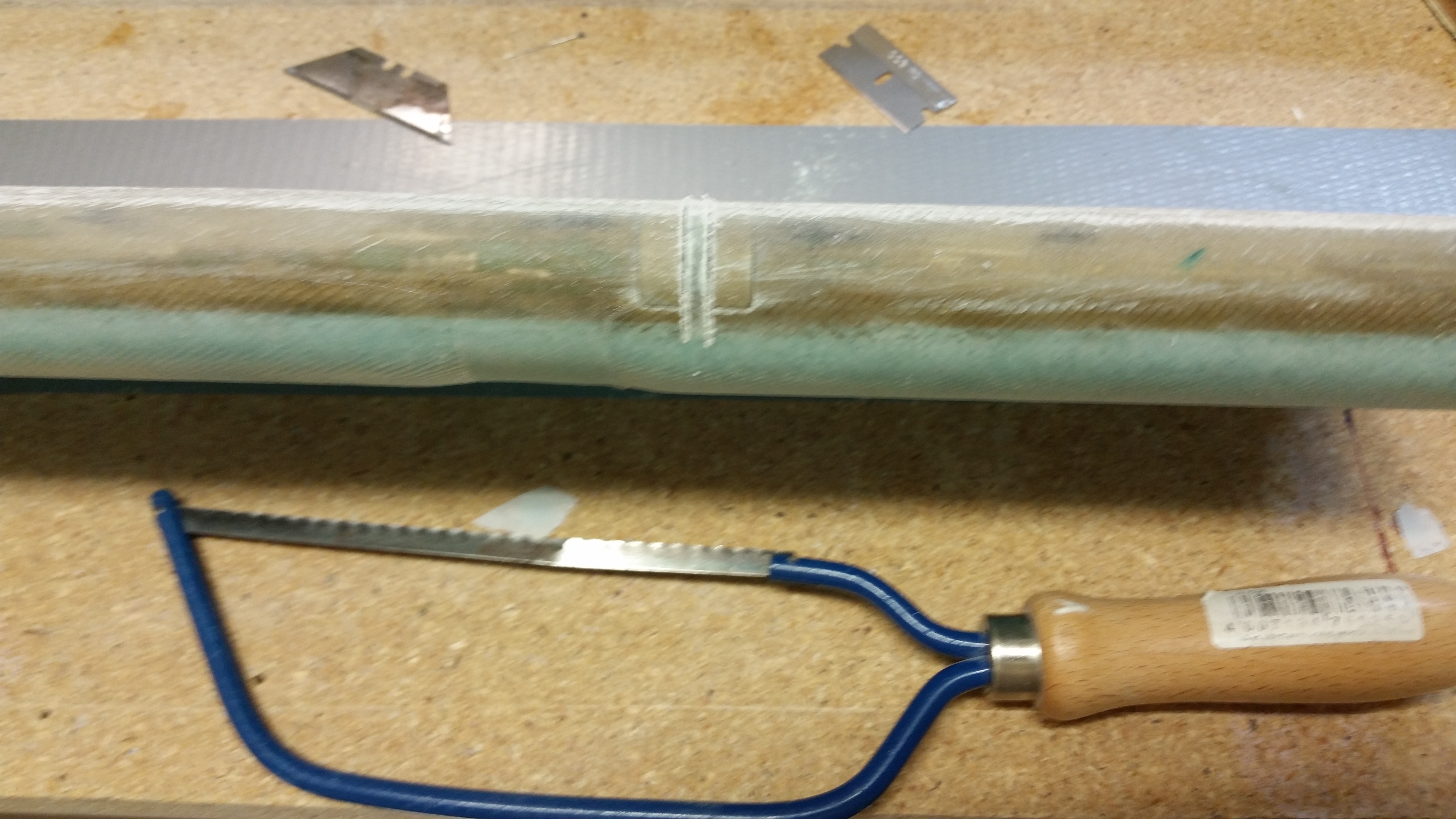
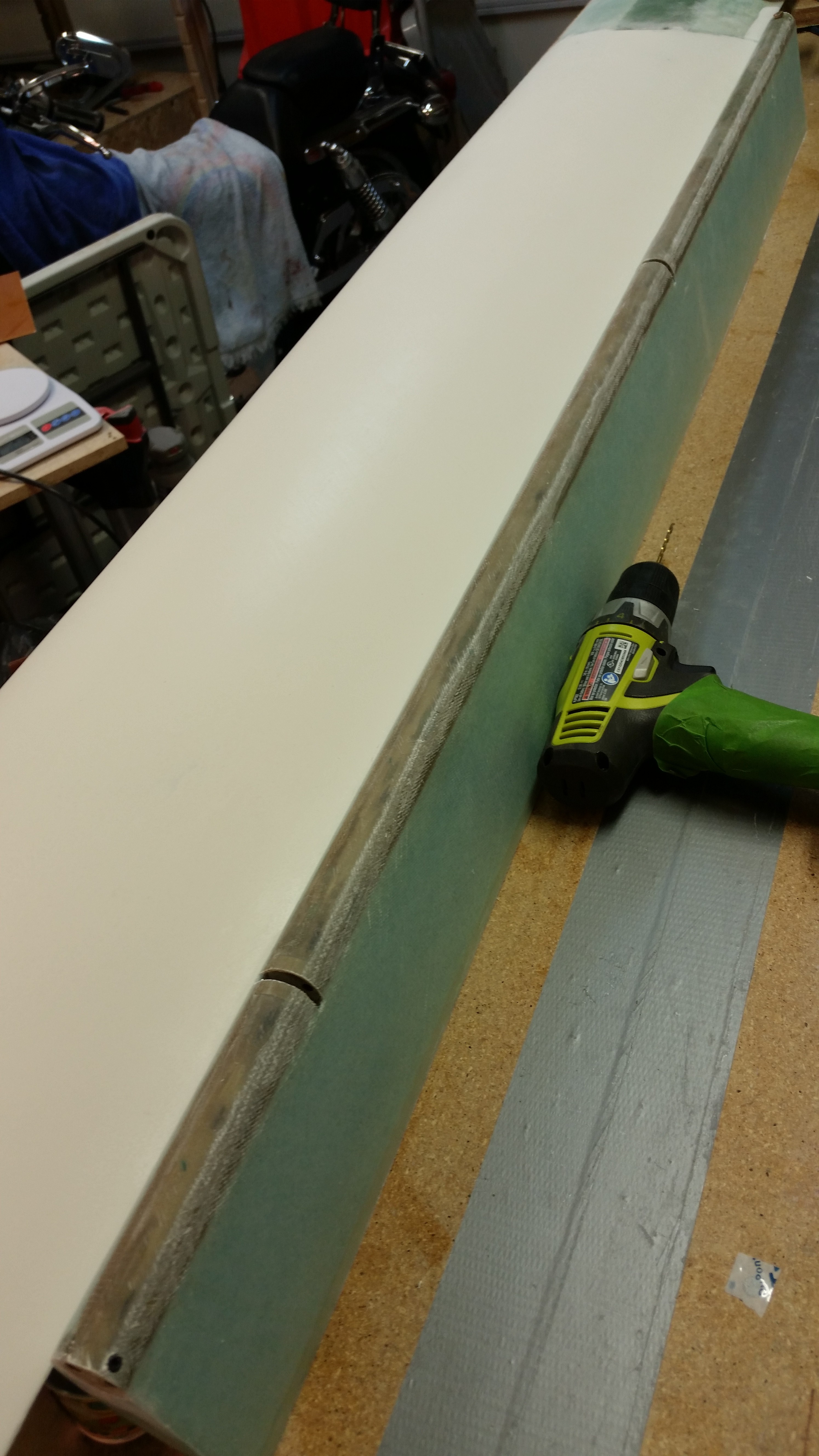
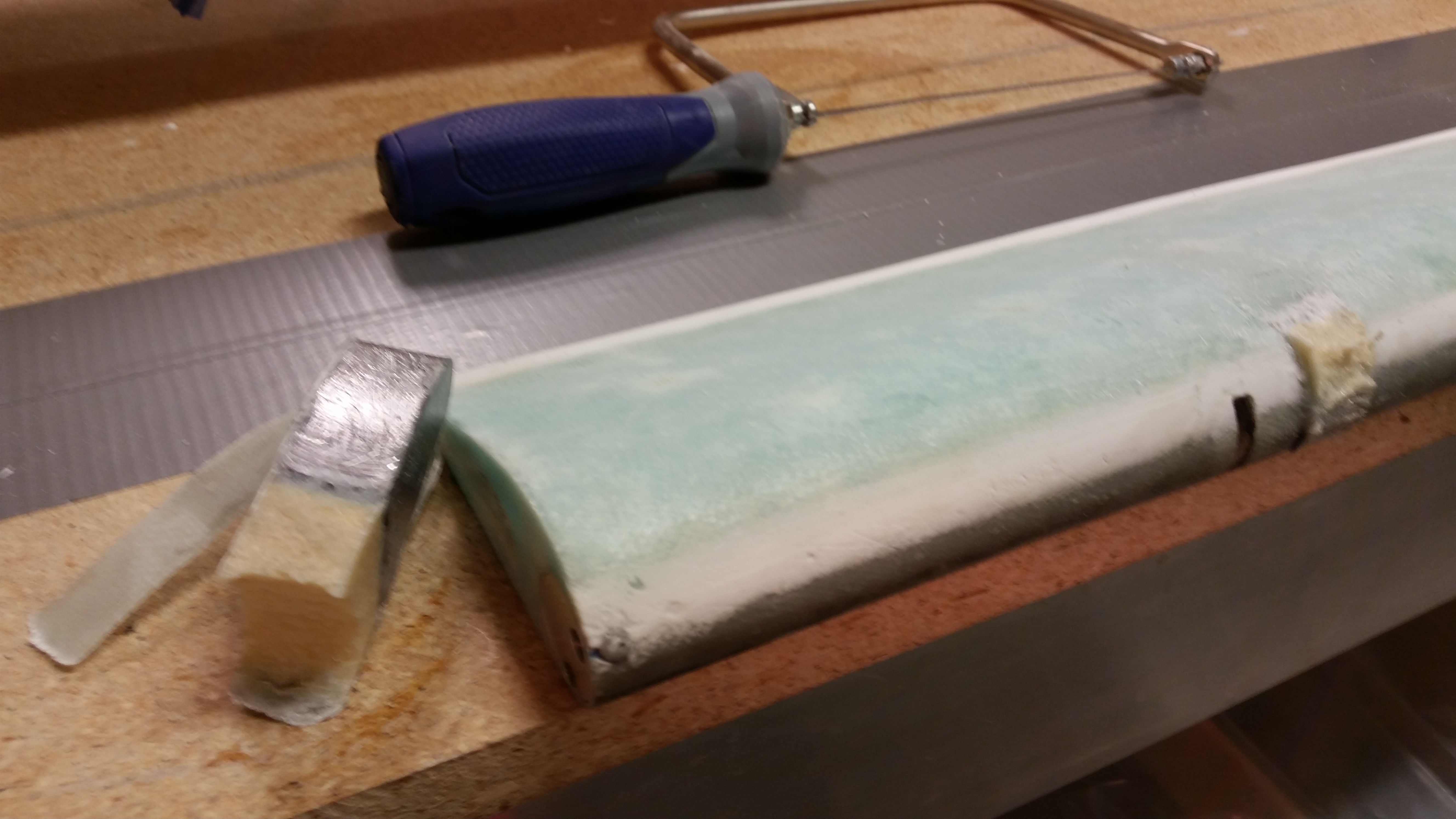
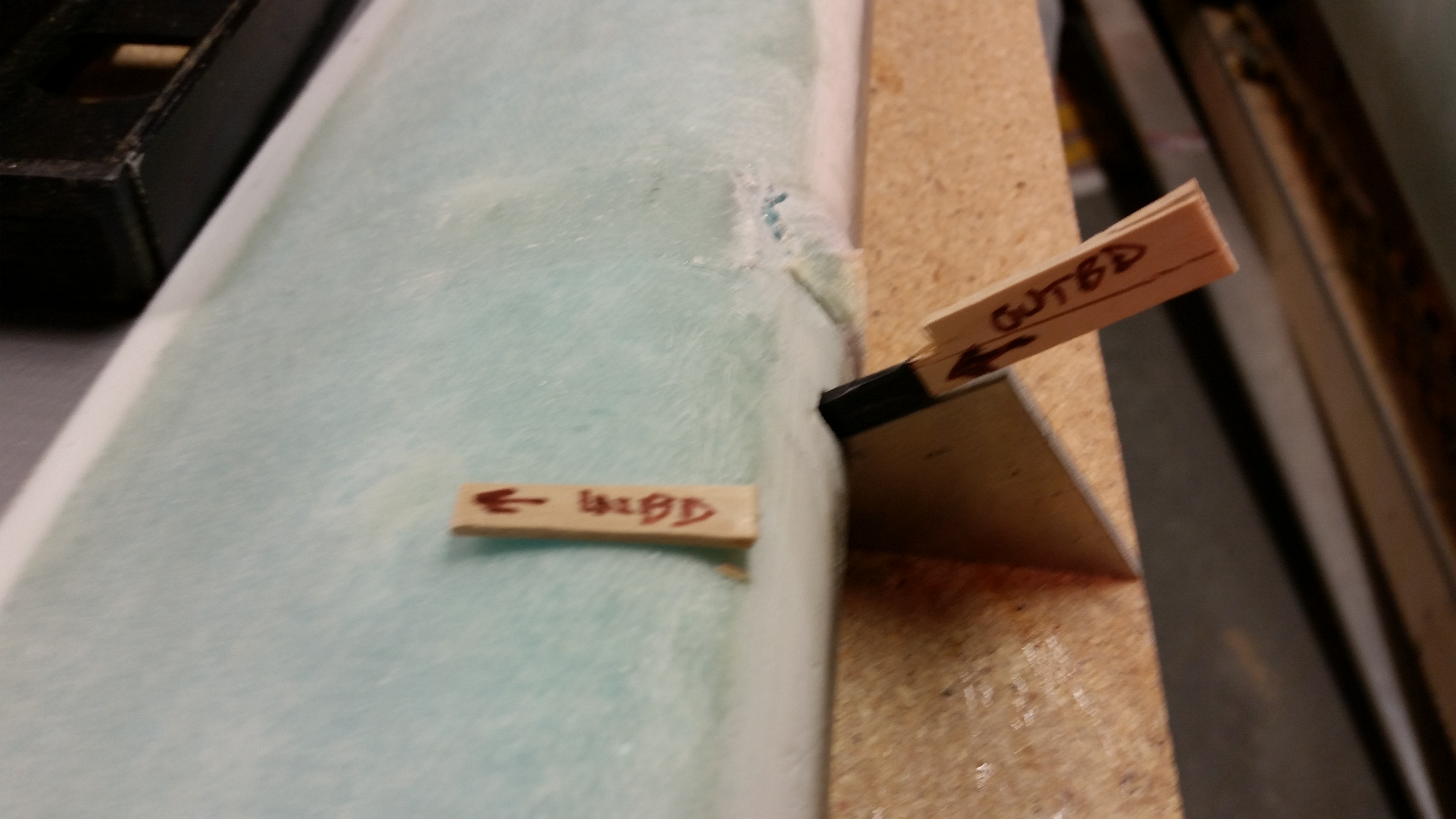
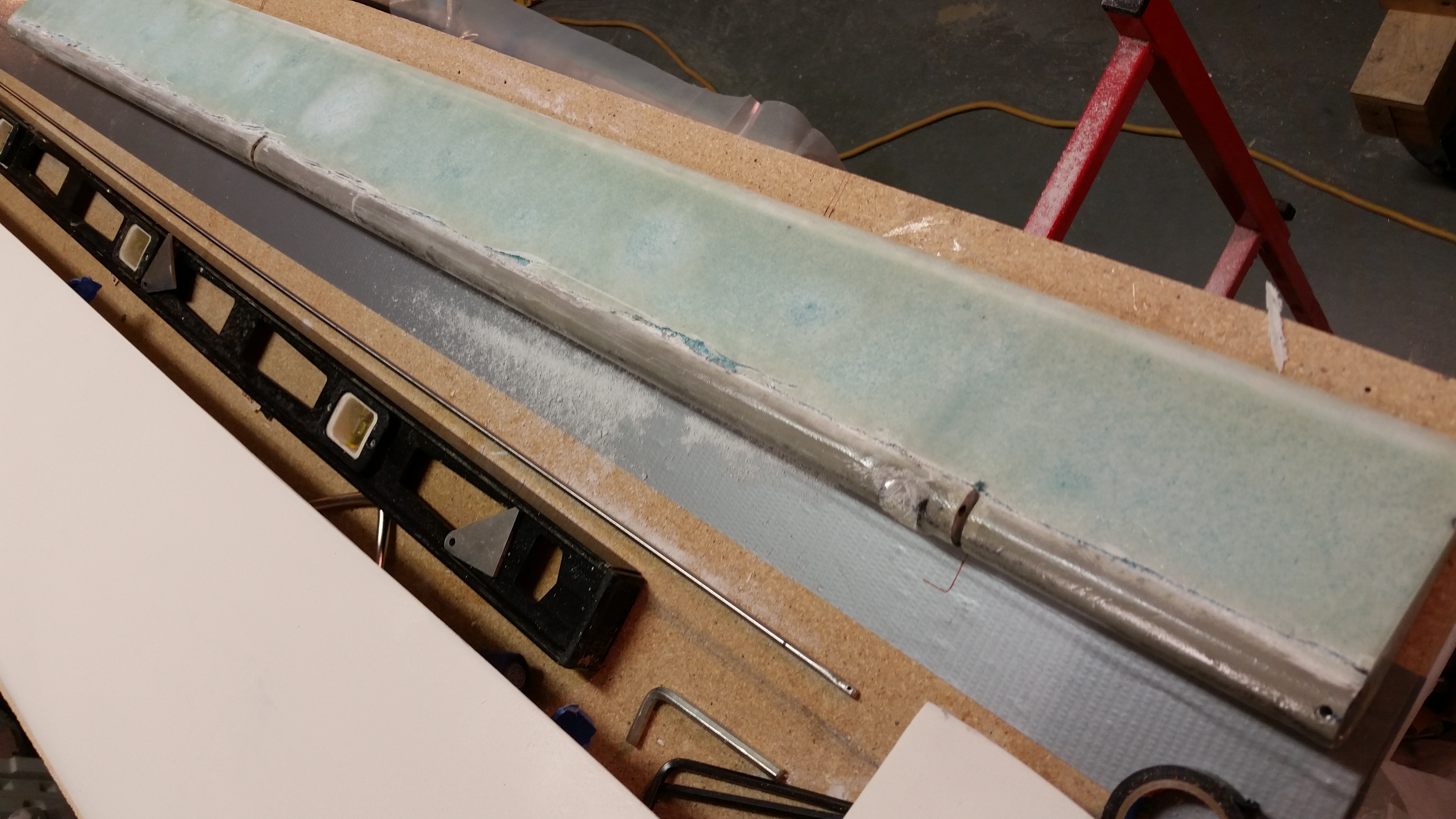
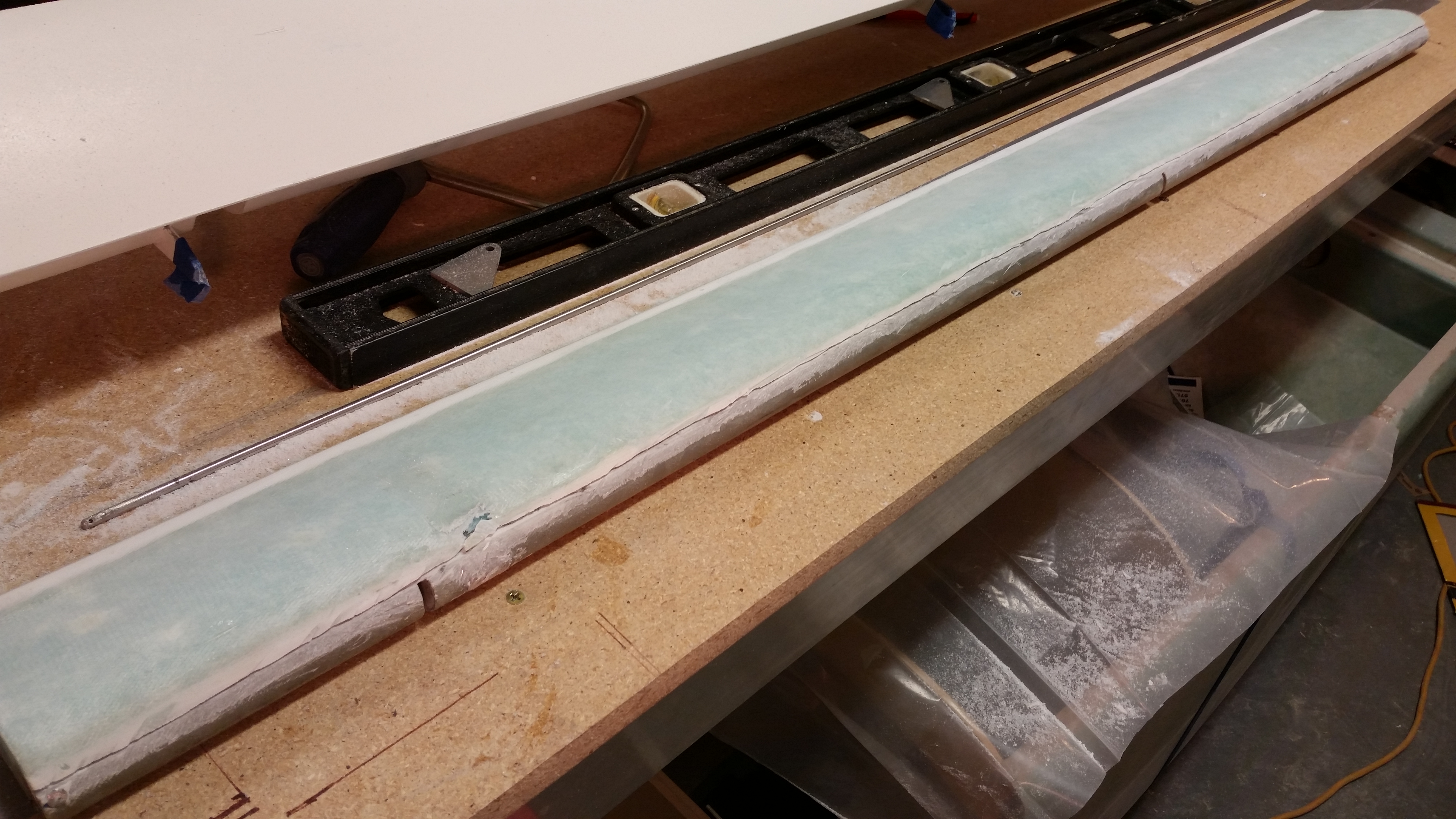
I took my German Praktiker special hand saw and cut the channels for the hinges.  After the major cut, I cleaned up the channels with a razor blade and removed the duct tape over the hinge pin holes.

Cutting hinge channelsCutting hinge channels

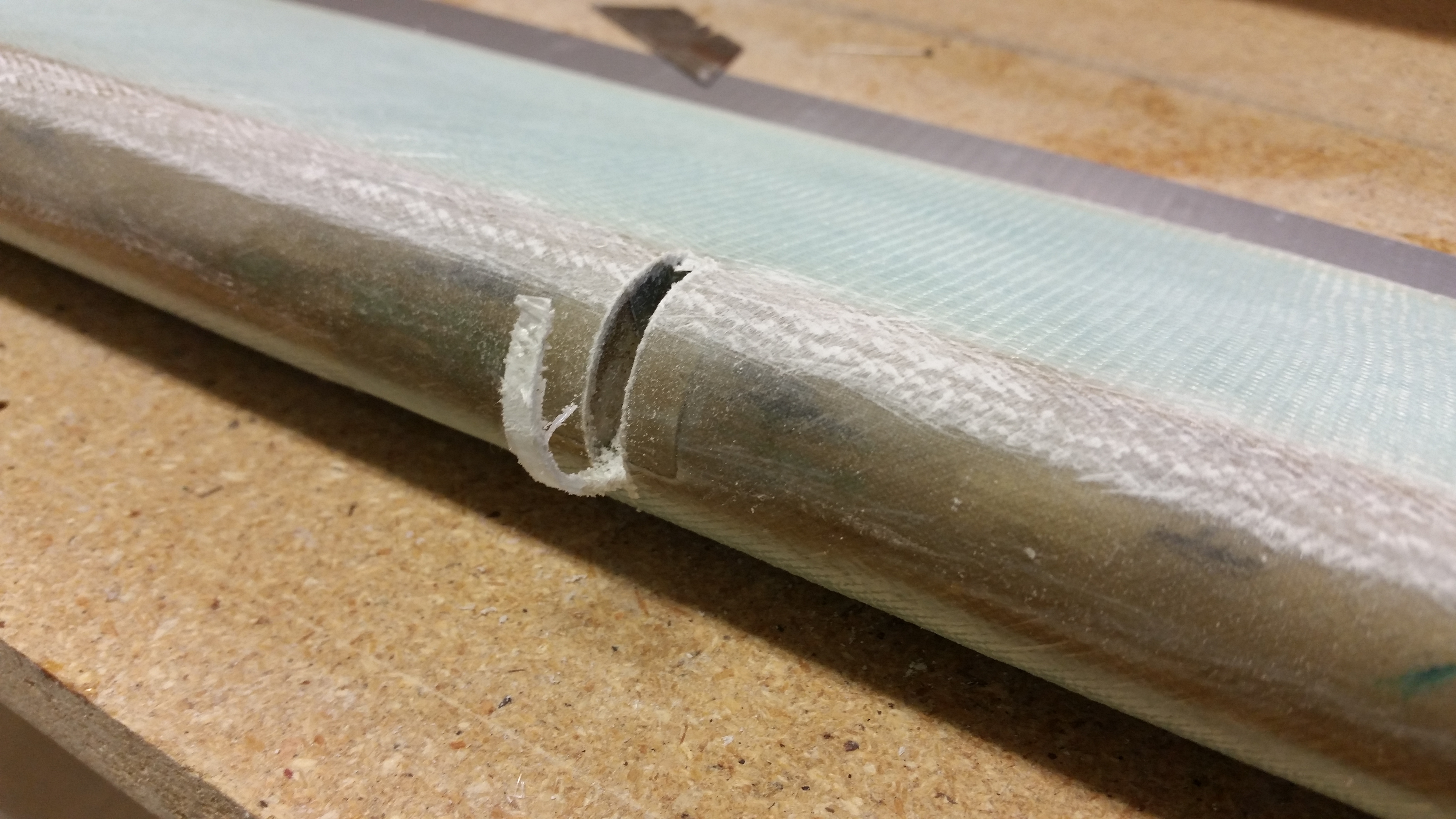
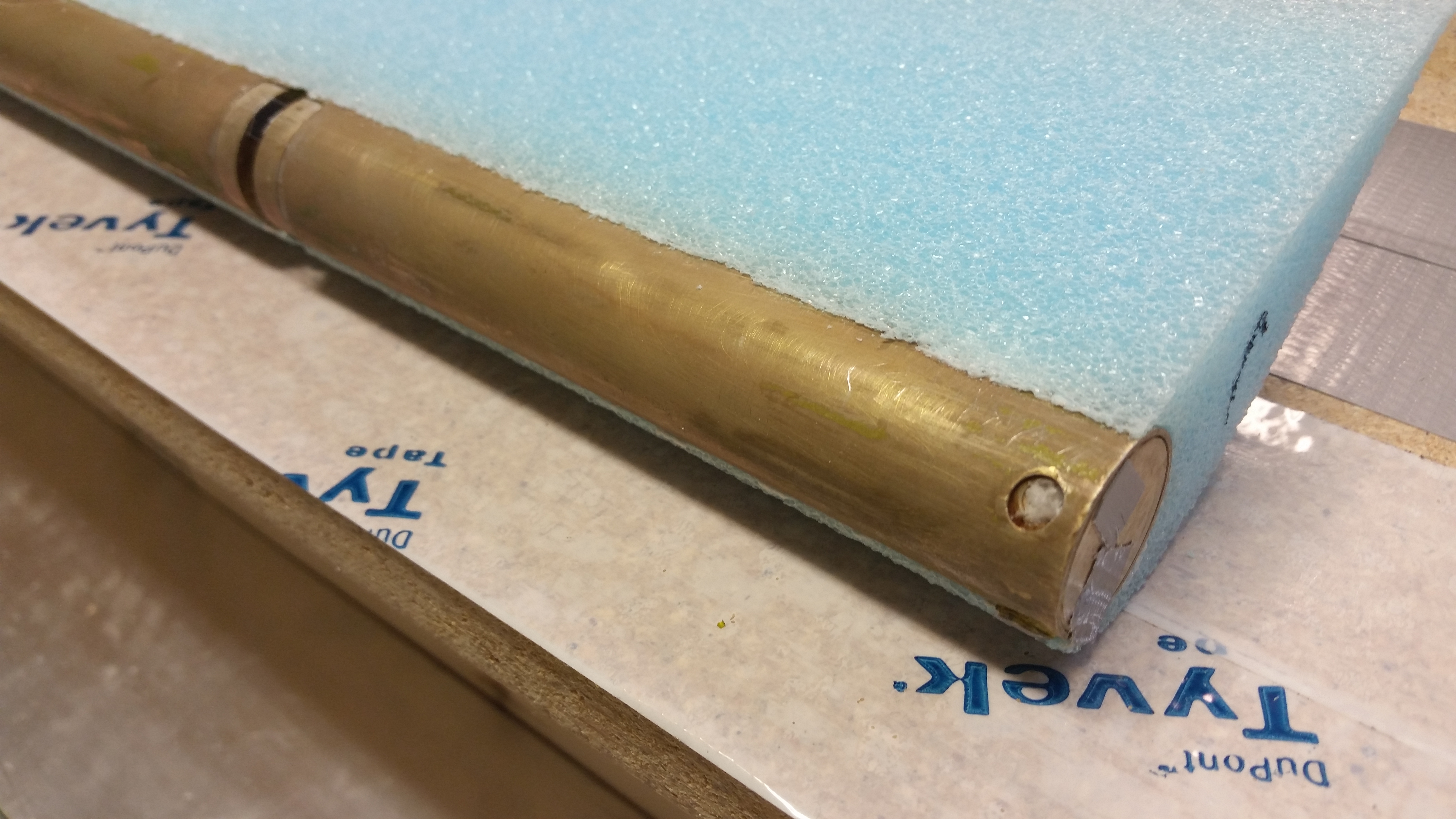
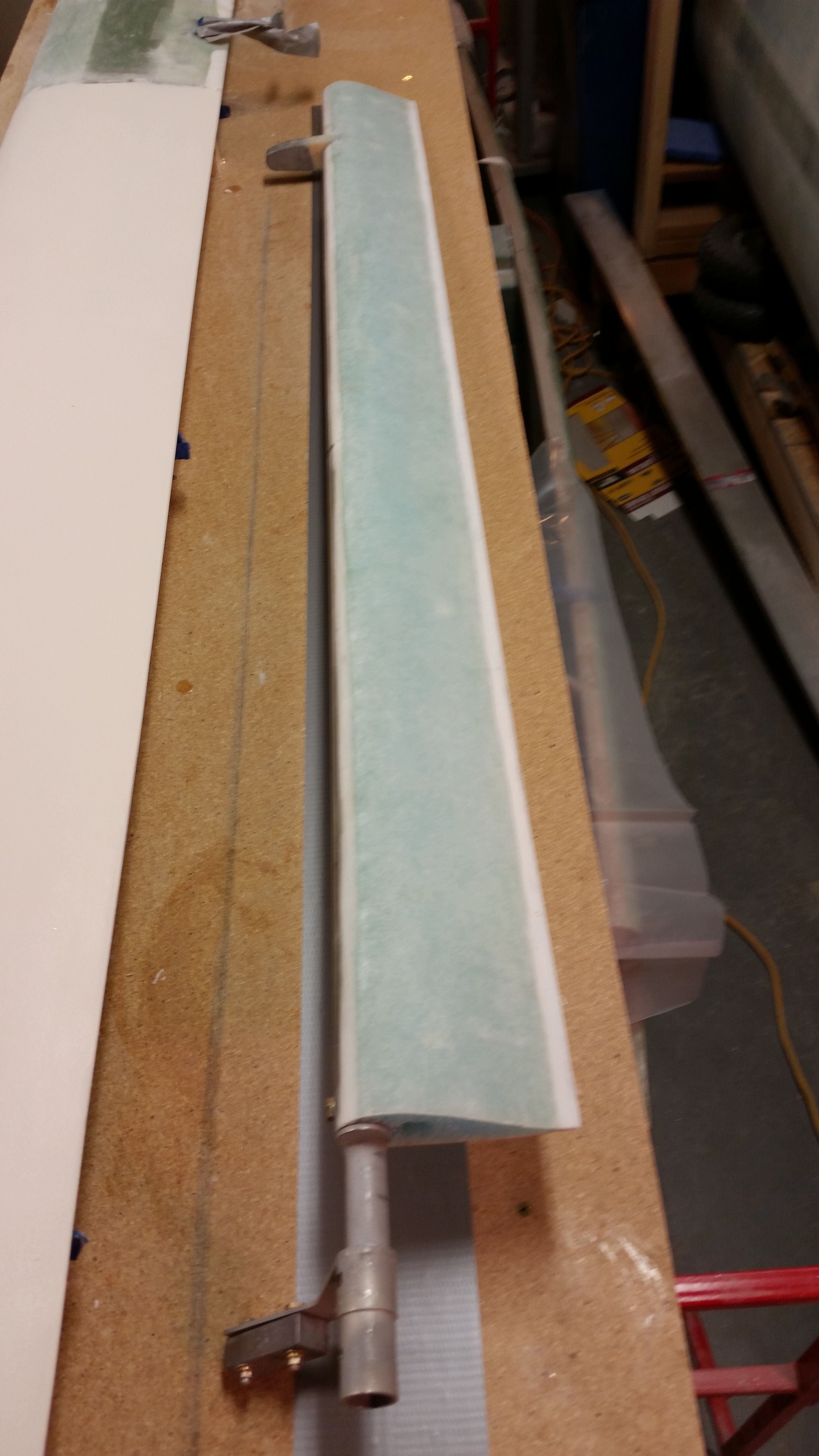
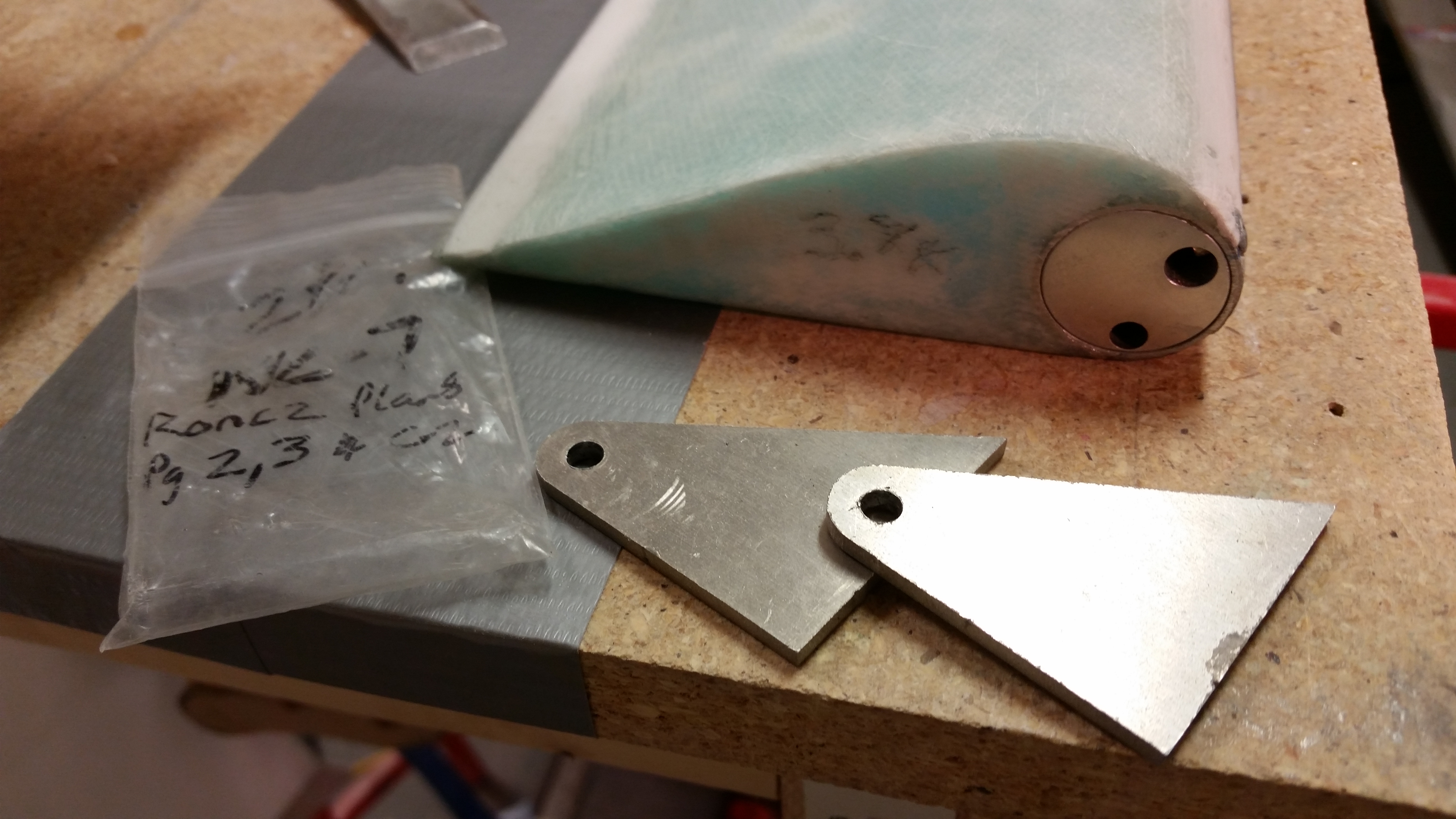
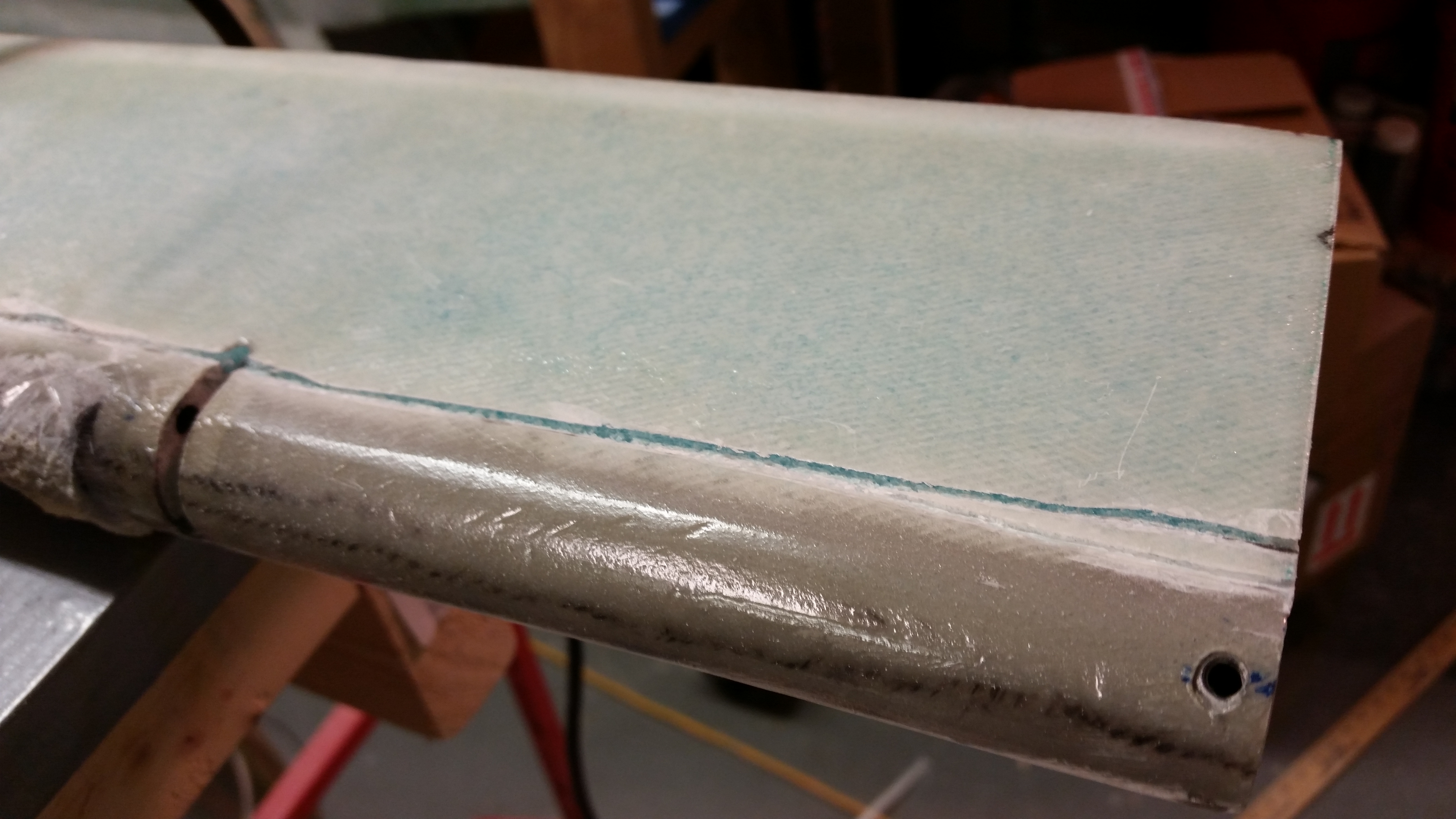
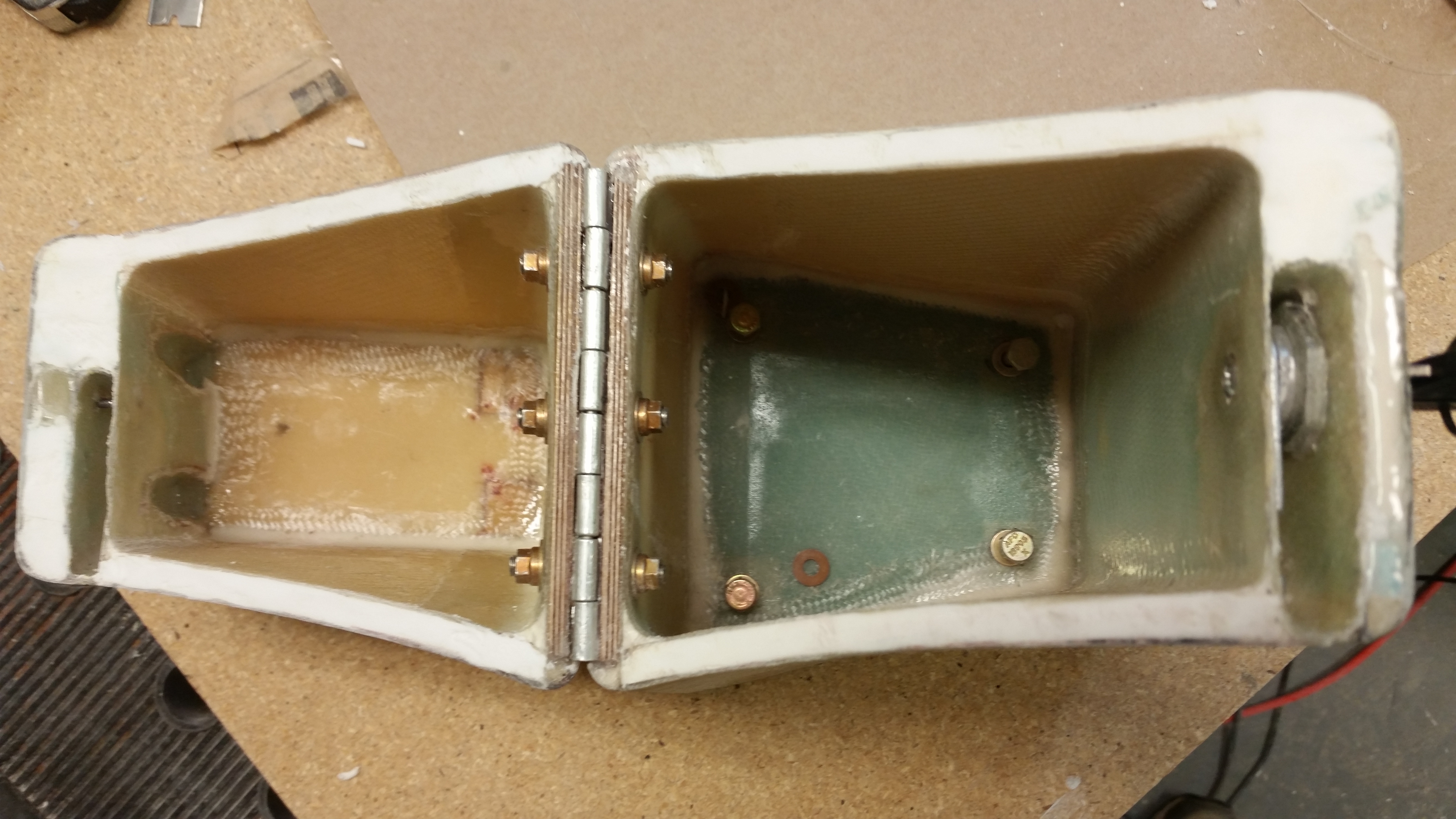
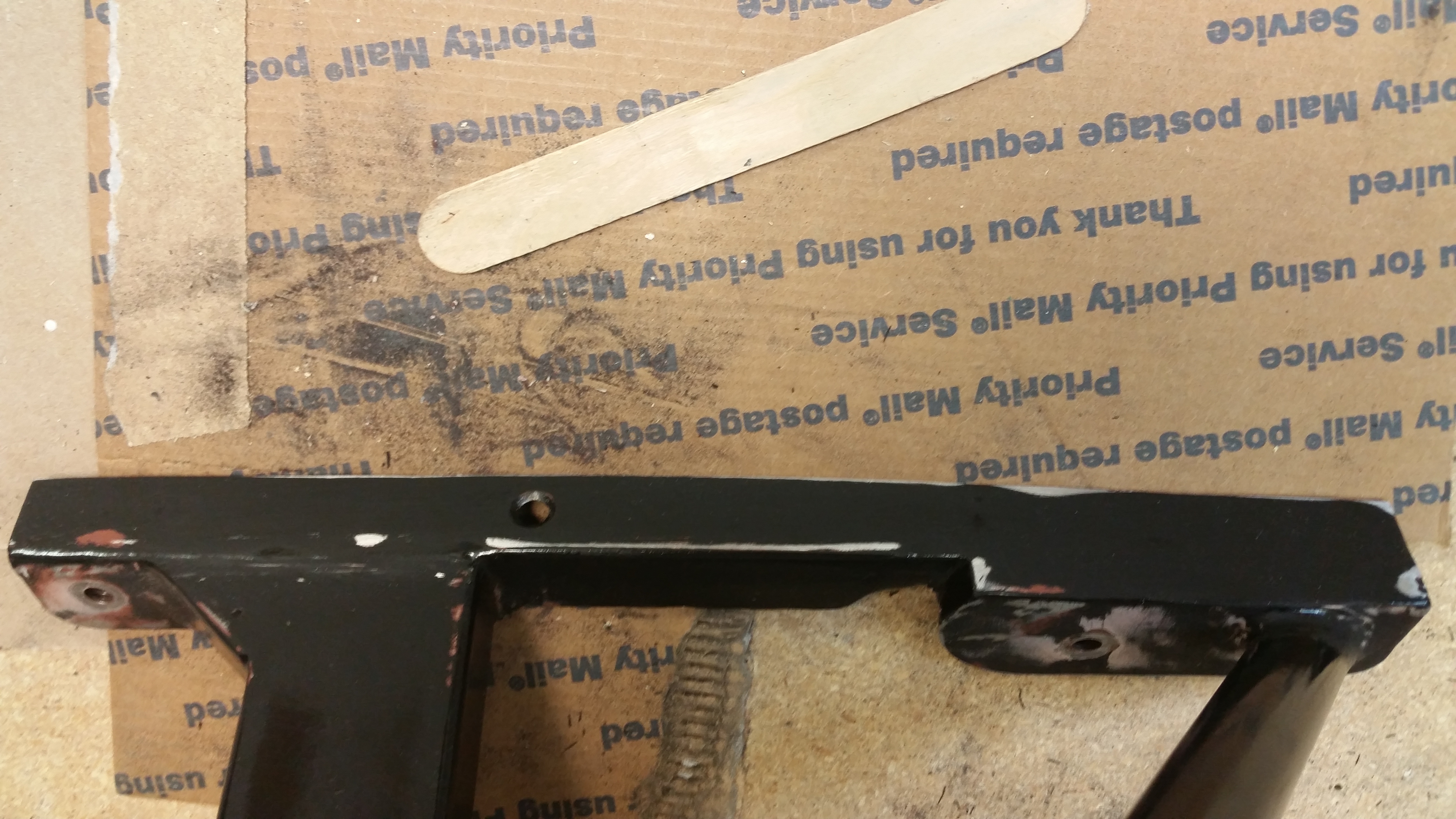
Below is a shot of the ancillary clean up, including the two hinge channels, the set screw hole at the close end and the torque office attach bolt hole at the opposite end.

Bits 'n pieces complete

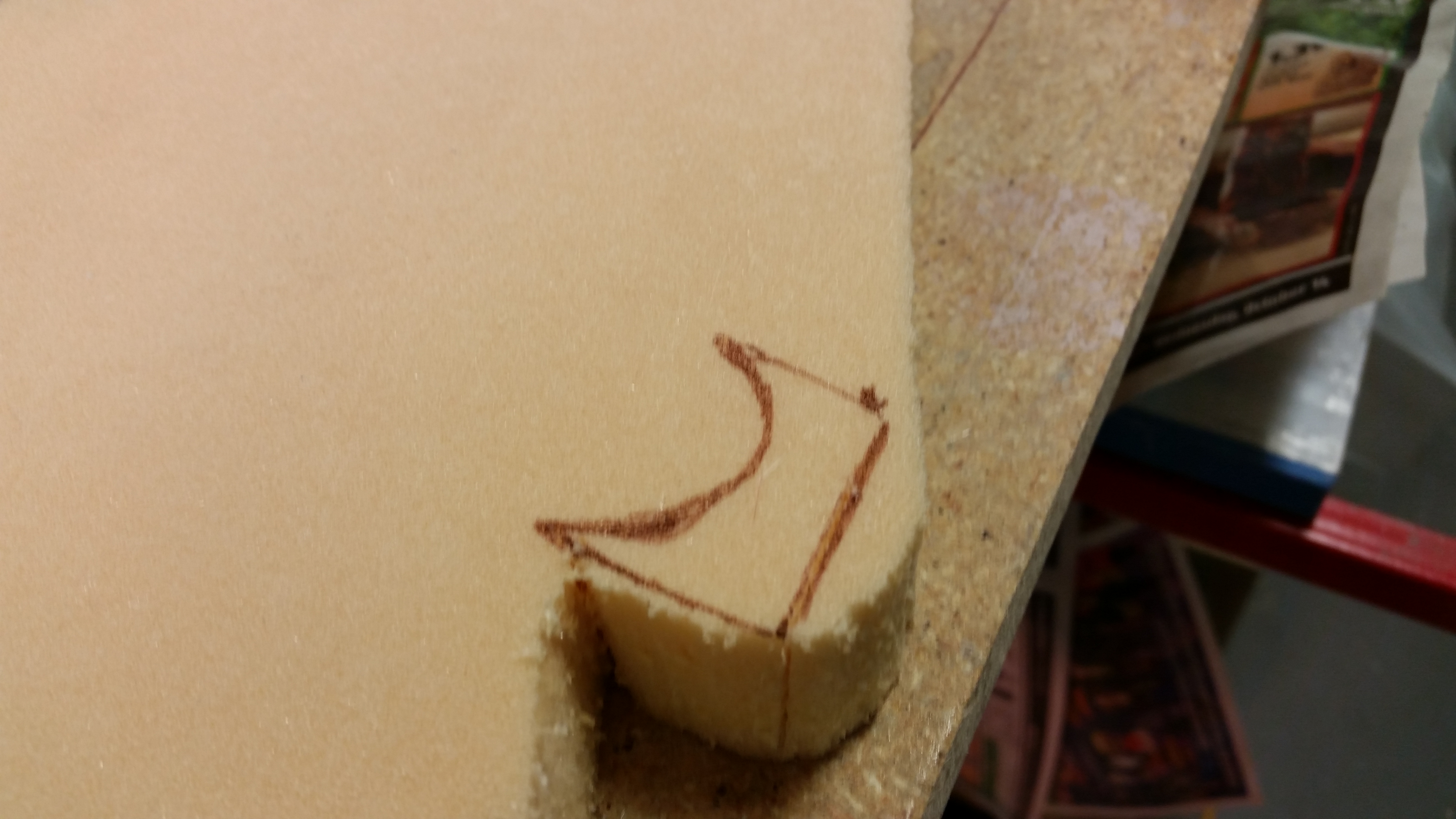
With the elevator pretty much completed, I turned my sights on the outboard elevator weight.  I marked up a new foam spacer on the H100 foam piece I have on hand. I then cut it out and shaped it with 36 grit sandpaper.

Outboard weight H100 spacer foam

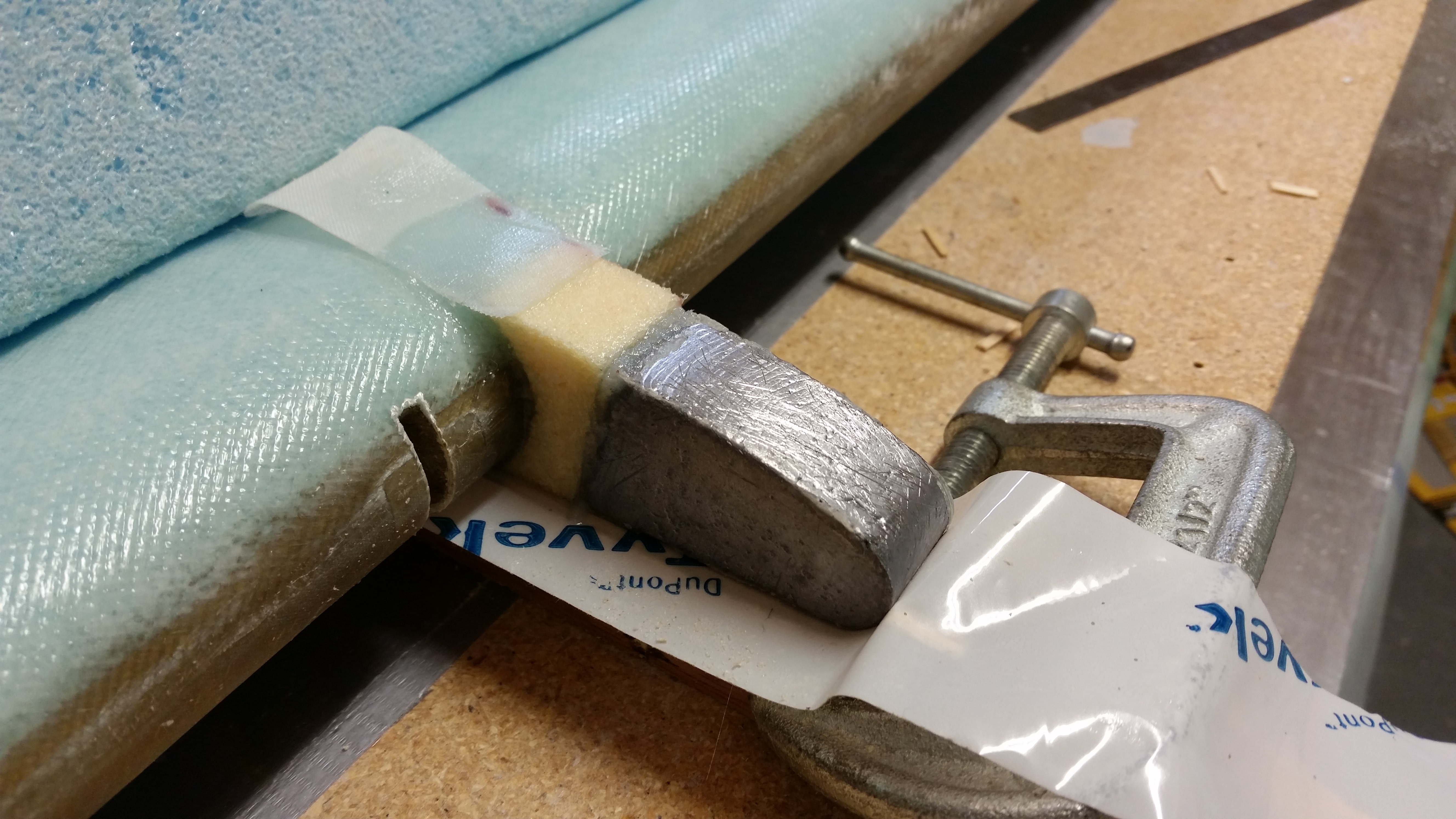
I worked for about 10-15 minutes to get the foam spacer shaped properly, and then floxed the weight & foam spacer in place using the templates.   Now, interestingly enough the plans say that you can use 5-minute glue, but of course I didn’t think of this until I had a batch of flox mixed up and of course I just bought some last week.

Oh, well, I just had to wait a little bit longer to glass it with 2 plies of UNI.

Outboard elevator weight floxed

A few hours later I cut out 2 strips of UNI and laid them up around the outboard elevator weight as per plans.  I then peel plied the layup before heading out for the evening.

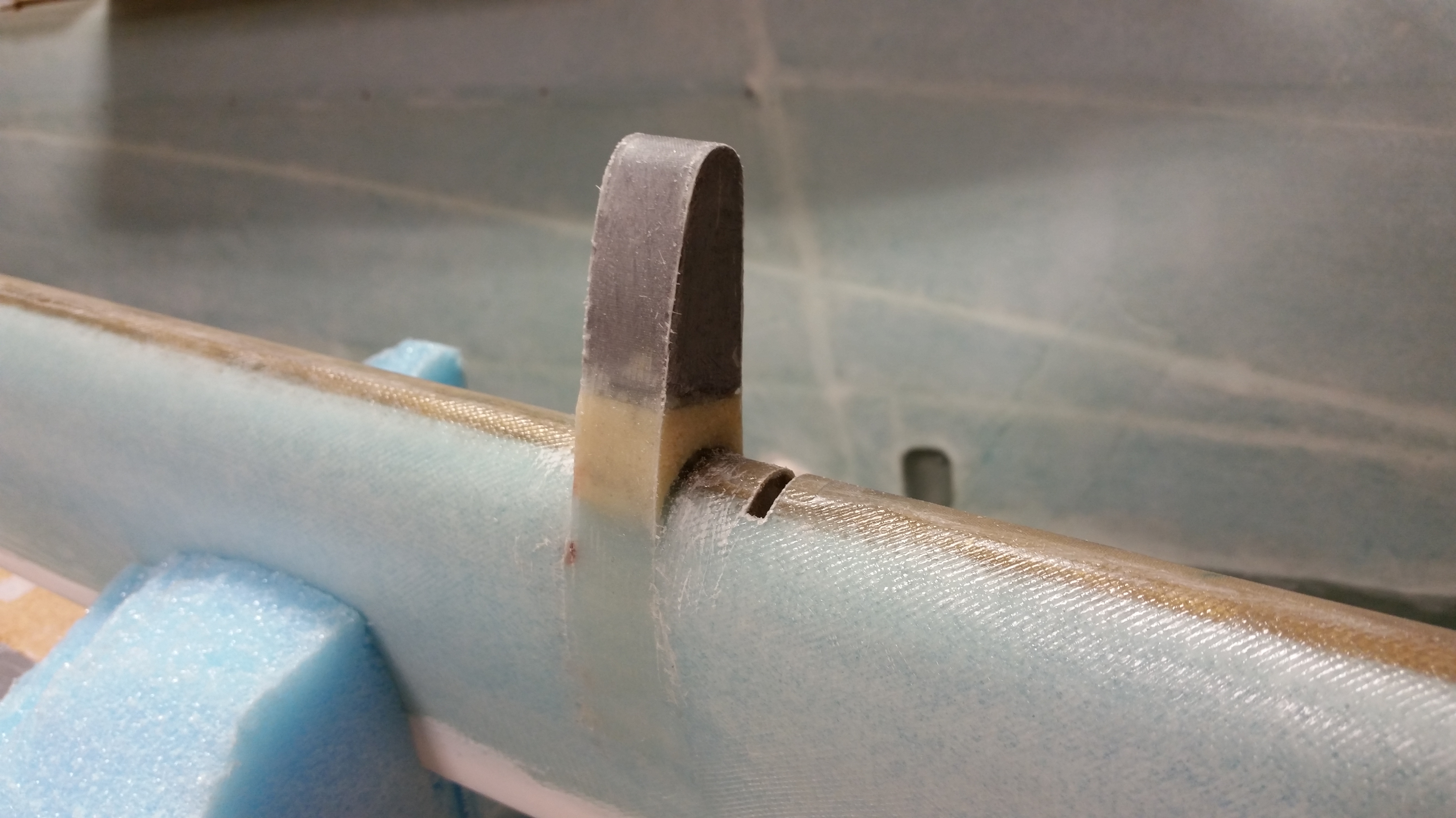
Outboard elevator weight glassed

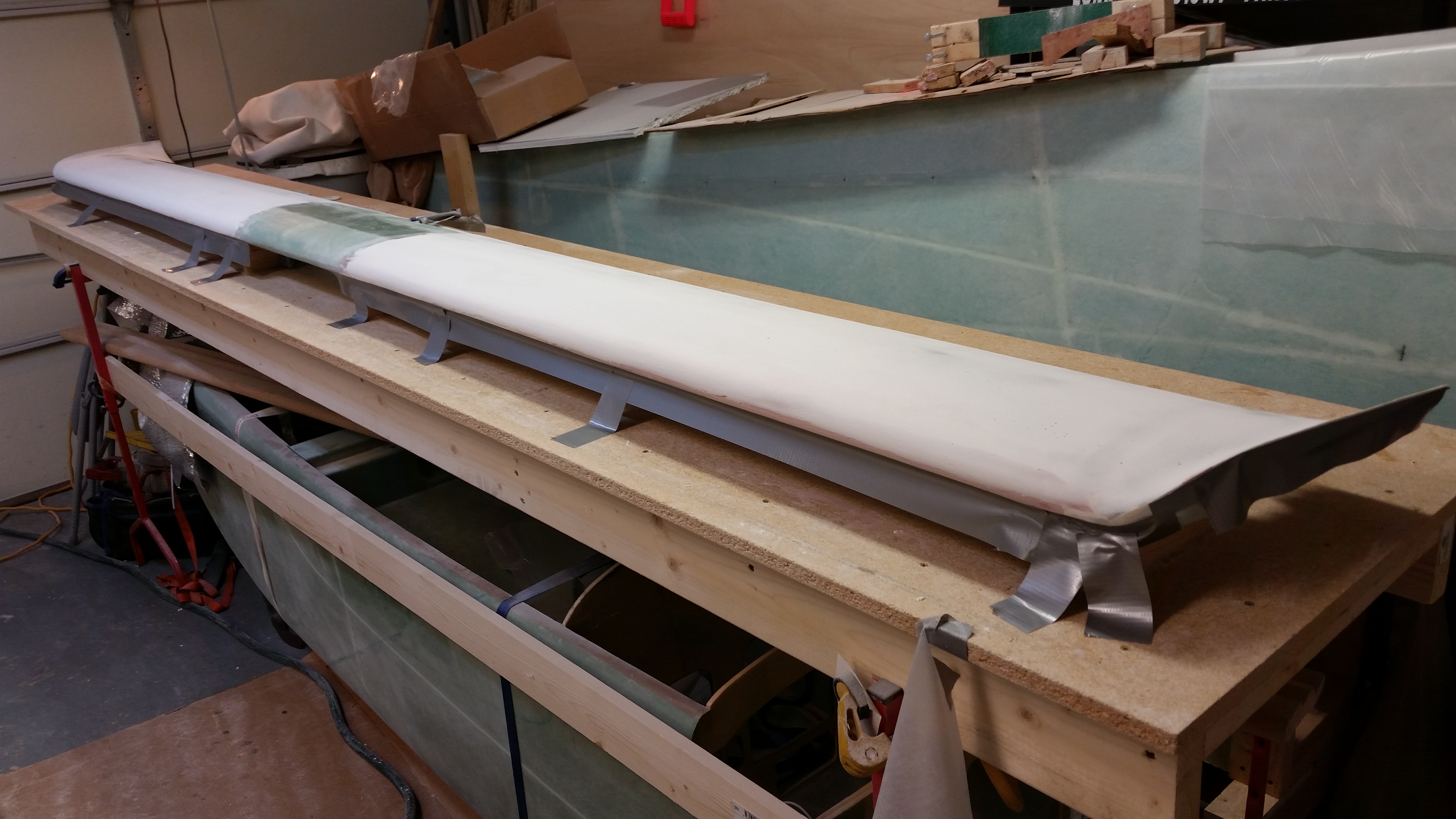
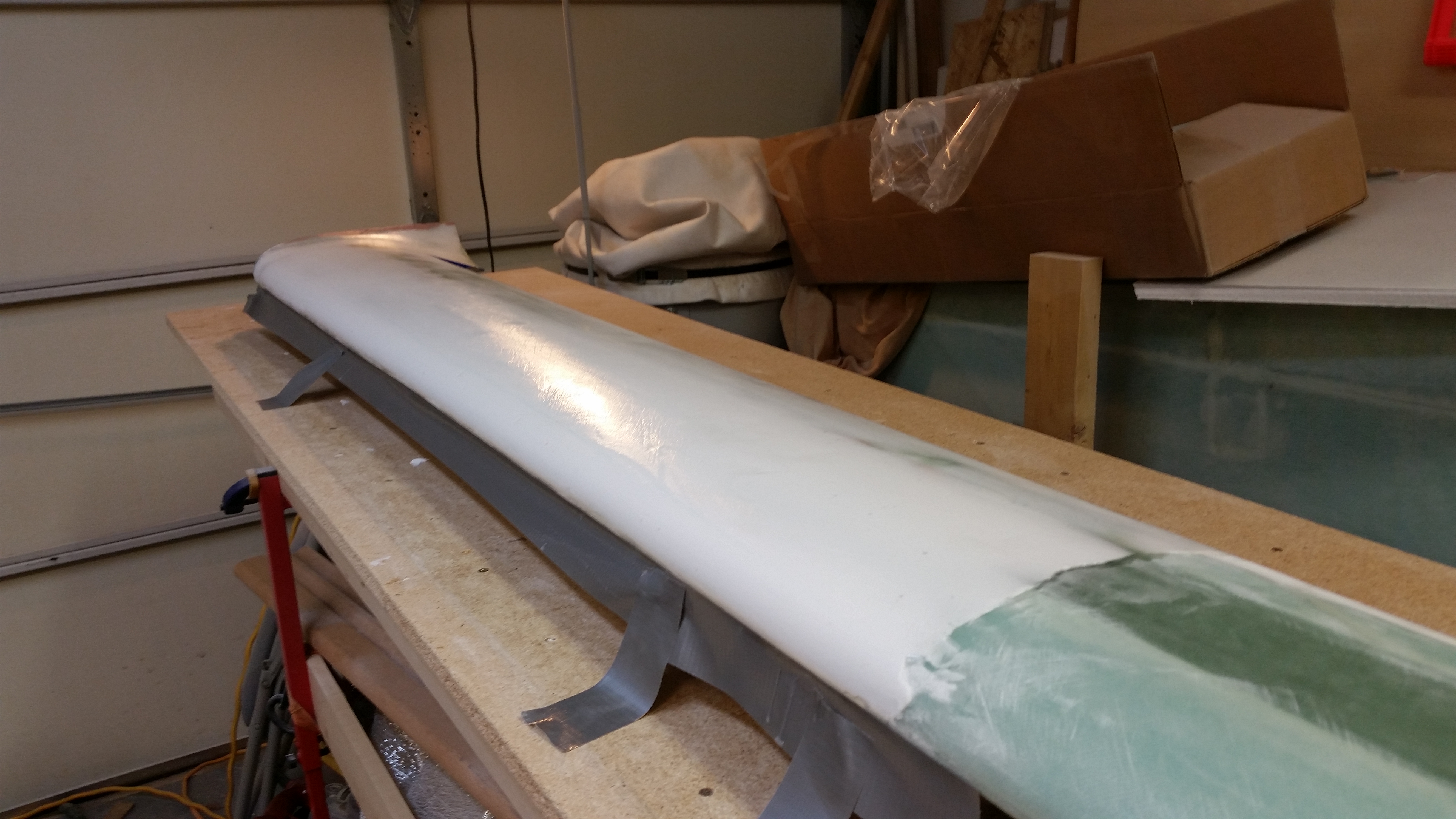
When I returned everything looked good & cured.  I pulled the peel ply, razor cut the glass, and then hit the edges very briefly with sandpaper.  Here’s the end result.

Outboard elevator weight cured

And with that folks, I’m calling the right elevator rebuild complete!


Chapter 11 & 13 – Glassing elevator

Here’s a shot of the trimmed elevator as it looked when I started working on it today.

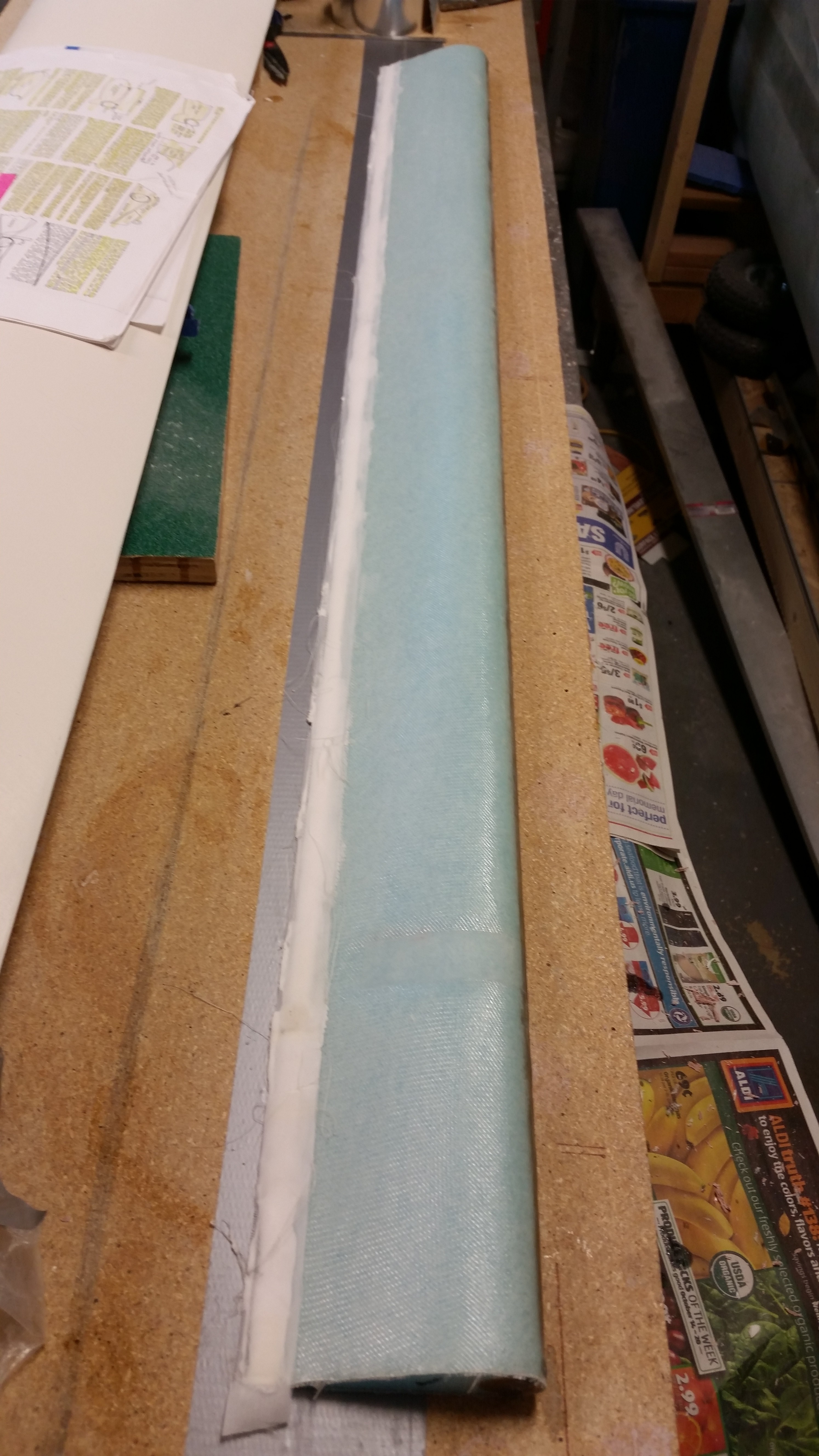
Cured & trimmed bottom elevator skin

I pulled the elevator off the workbench and was happy that by using the foil tape I had NO divots on the top of my elevator foam.  In addition, you’ll note the blobs of 5 minute glue on the table.

5-min glue blobs

For whatever reason the 5-minute glue blobs came off rather easily.  After about 5 minutes with a chisel and a razor glade the table was clean.

Glassed elevator bottom

I then sanded the TE even.  After sanding I marked a line about 0.32″ forward of the TE for the glass-to-glass continuity between top & bottom elevator skins.

Marked TE for trim

After removing the foam with my razor knife, i sanded down the TE glass with a sanding board.

TE initial trim

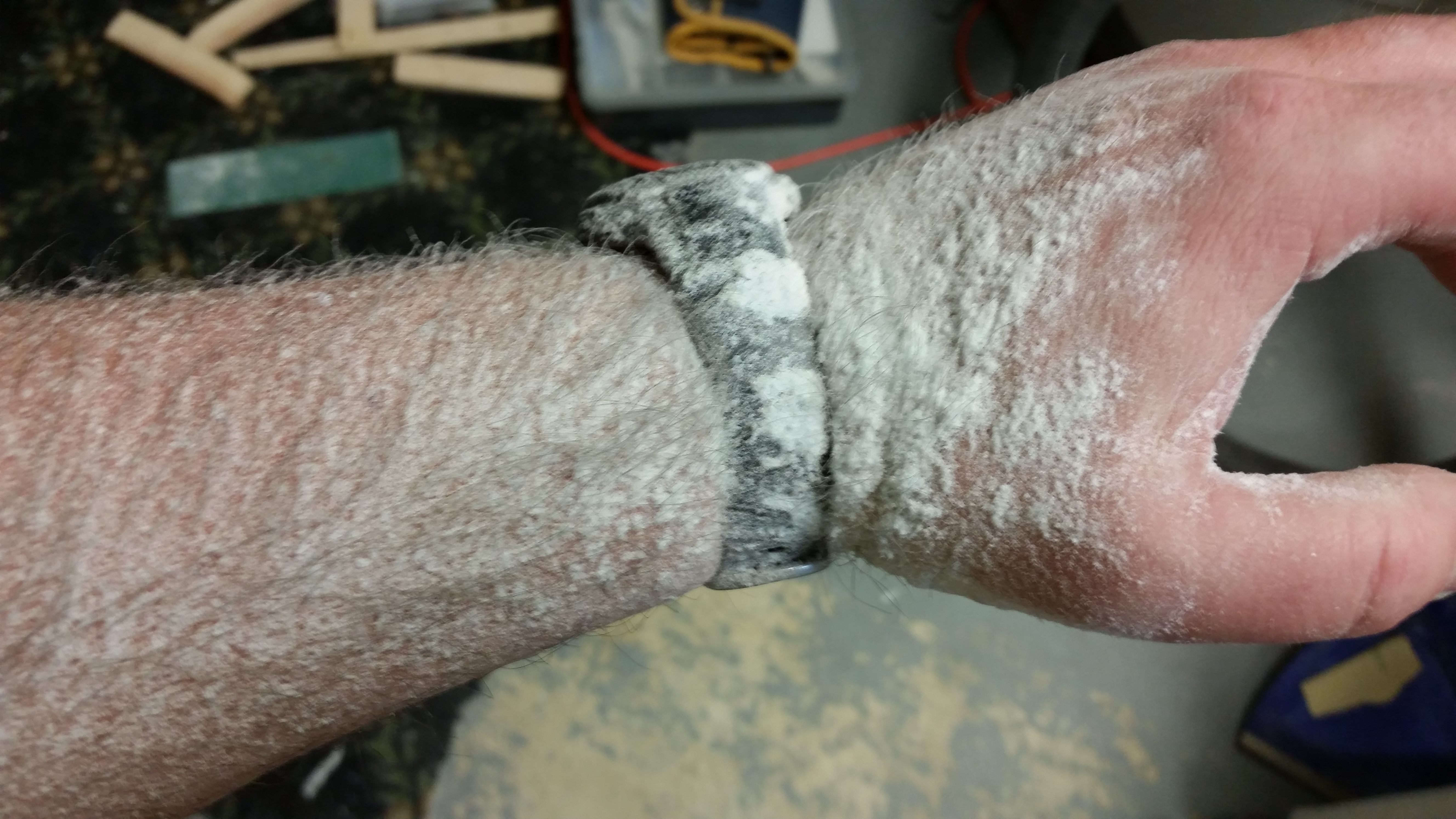
I then Dremeled the remaining crud off the TE to finalize the prep.  And here’s the results: ha!

Dremel dust

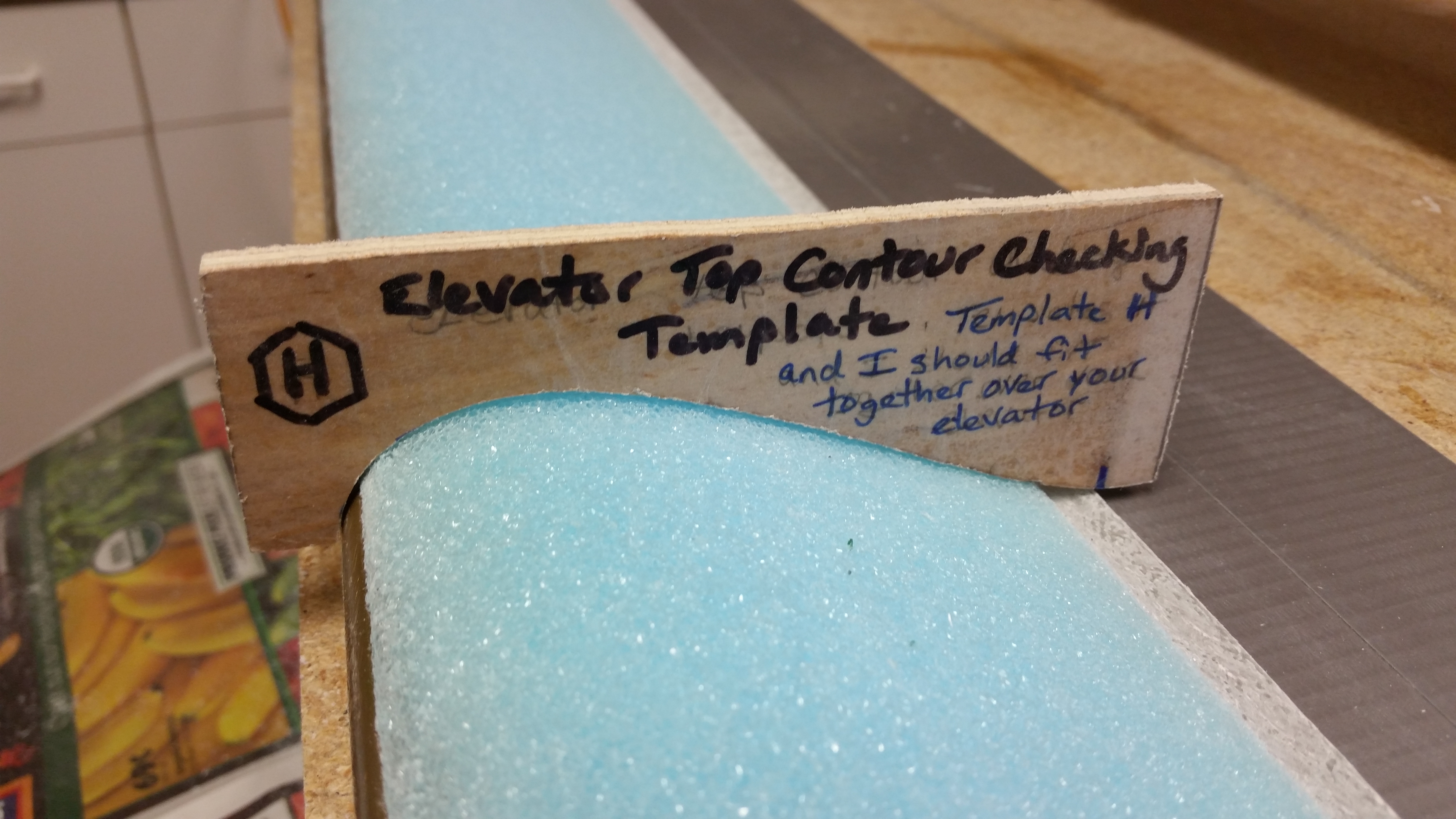
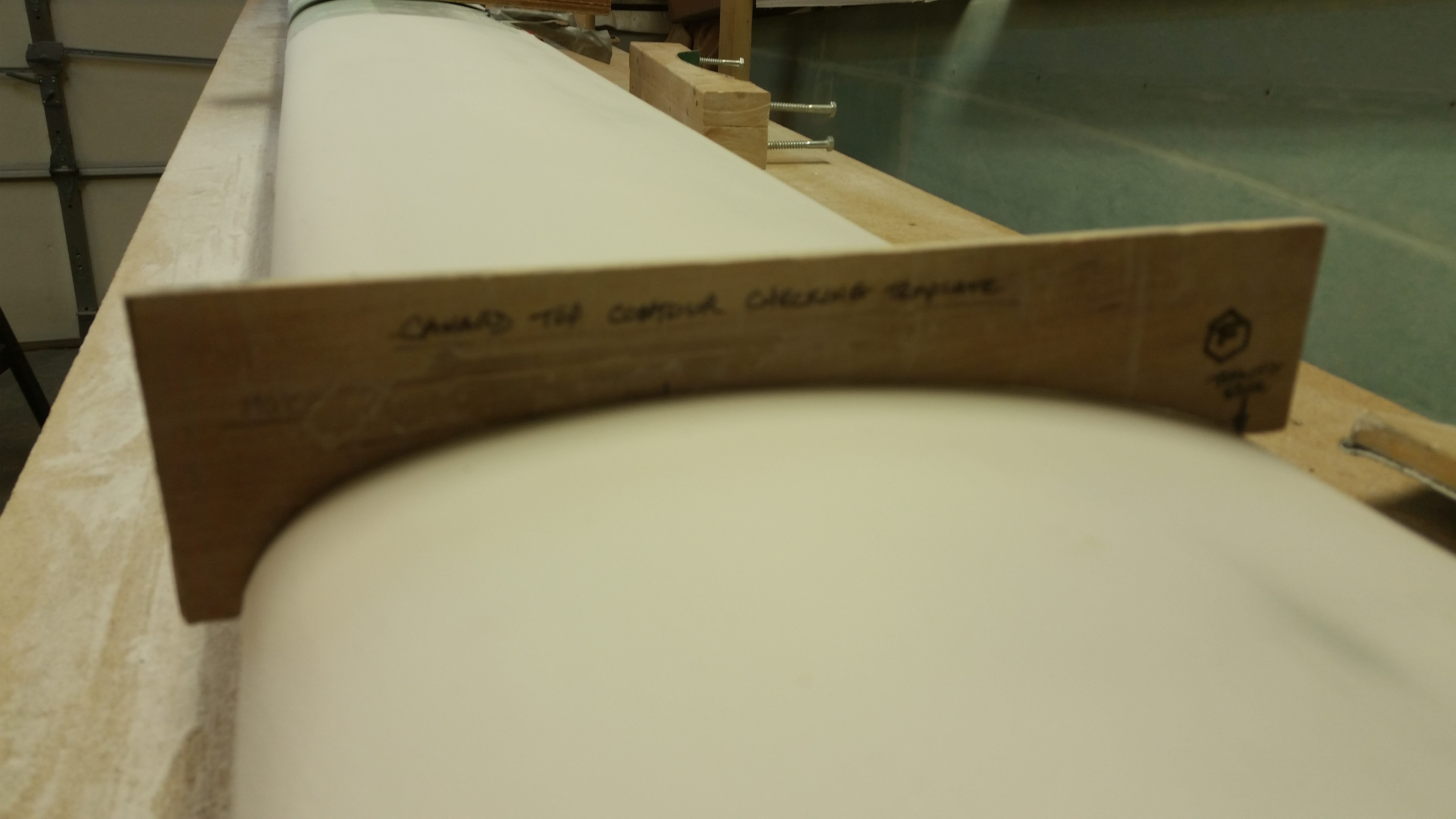
I again did a quick check of the top contour with the “H” template.

Elevator contour check

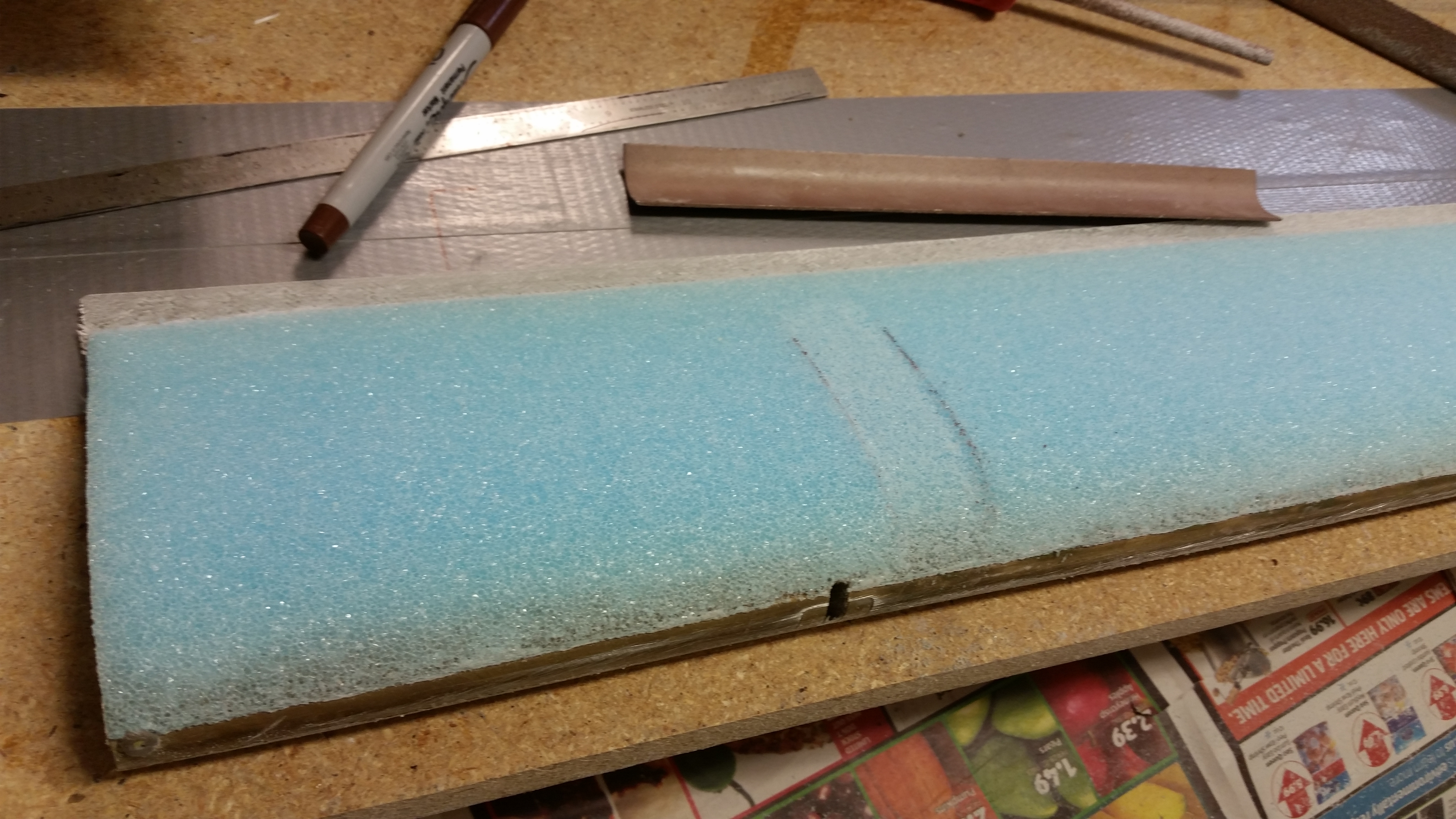
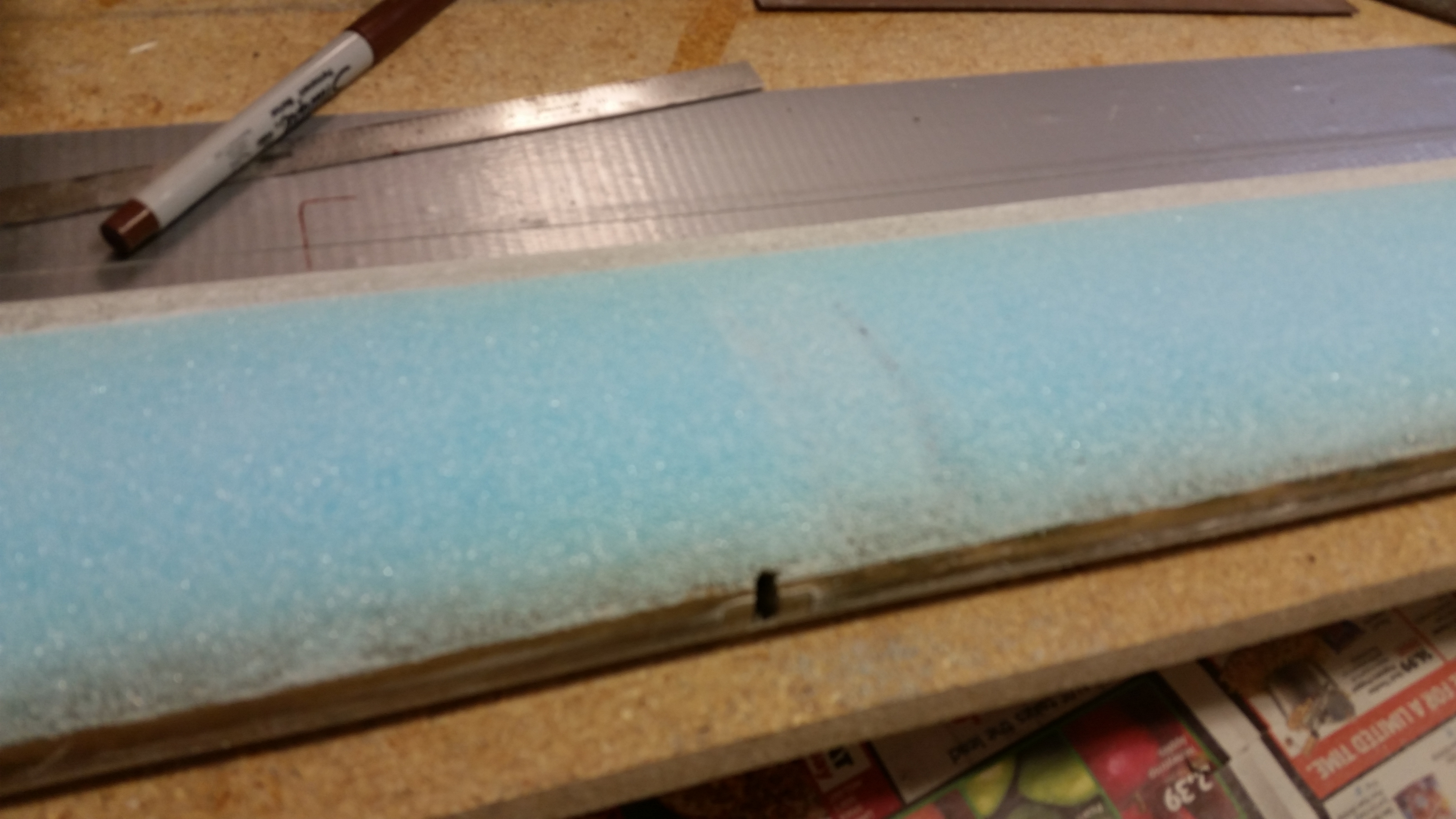
Although I forgot to do this on the bottom (Doh!) I did remember to add the depression in the foam for the UNI plies that attach the outboard elevator weight.

Depression for outboard weight

Depression for outboard weight

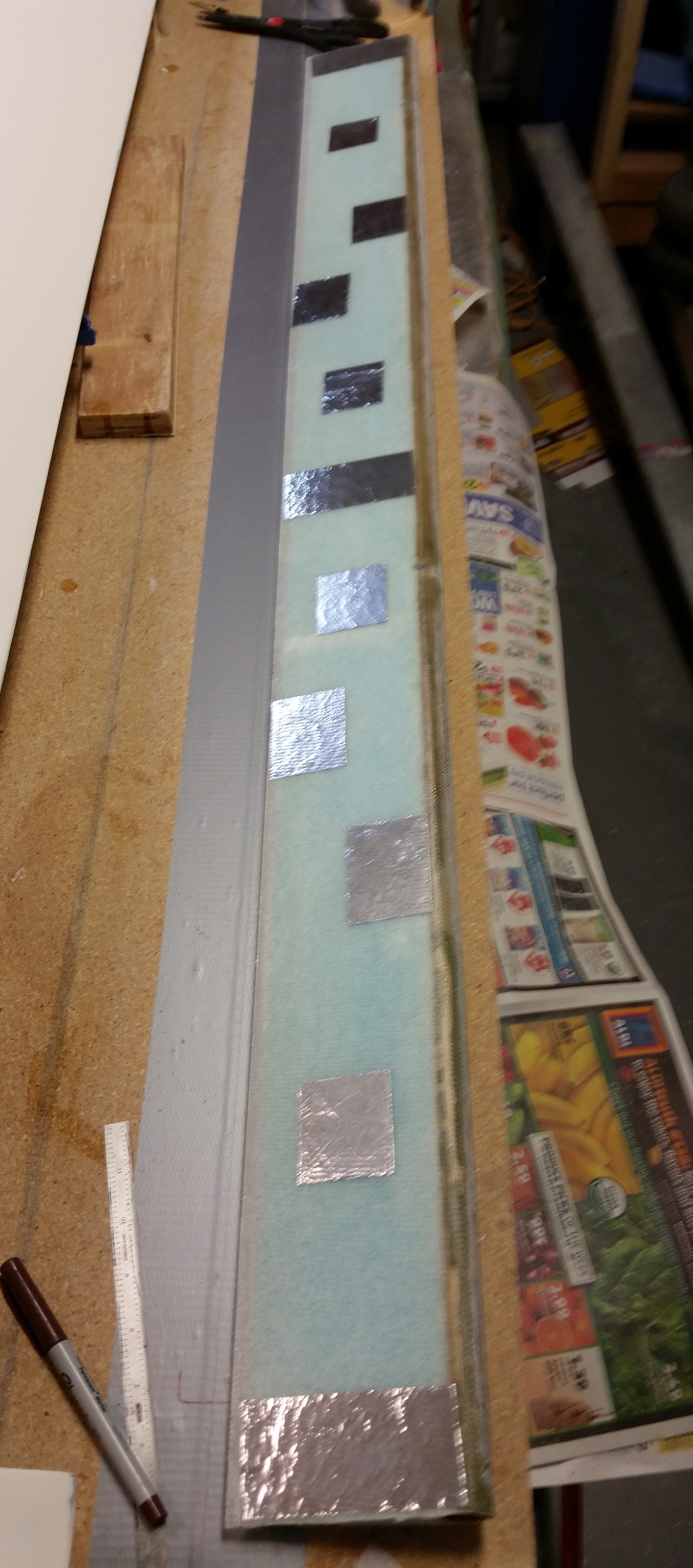
After I finished all the prep actions for the layup, I flipped the elevator over and applied foil tape to the underside of the elevator.  Again, I’m doing this to avoid all the issues I had with the previous elevator, and exactly the reason why I’m rebuilding this elevator!

Foil taped elevator bottom

After applying SMALL Bondo blobs to the foil tape pieces I mounted the elevator to the table and then weighed it down with sandbags.

Bondo'd elevator

After affixing the elevator to the workbench with Bondo I had about an hour to go before a work webinar so I started working on the nose gear actuator wiring since I knew I didn’t have enough time to finish the top elevator skin layup.

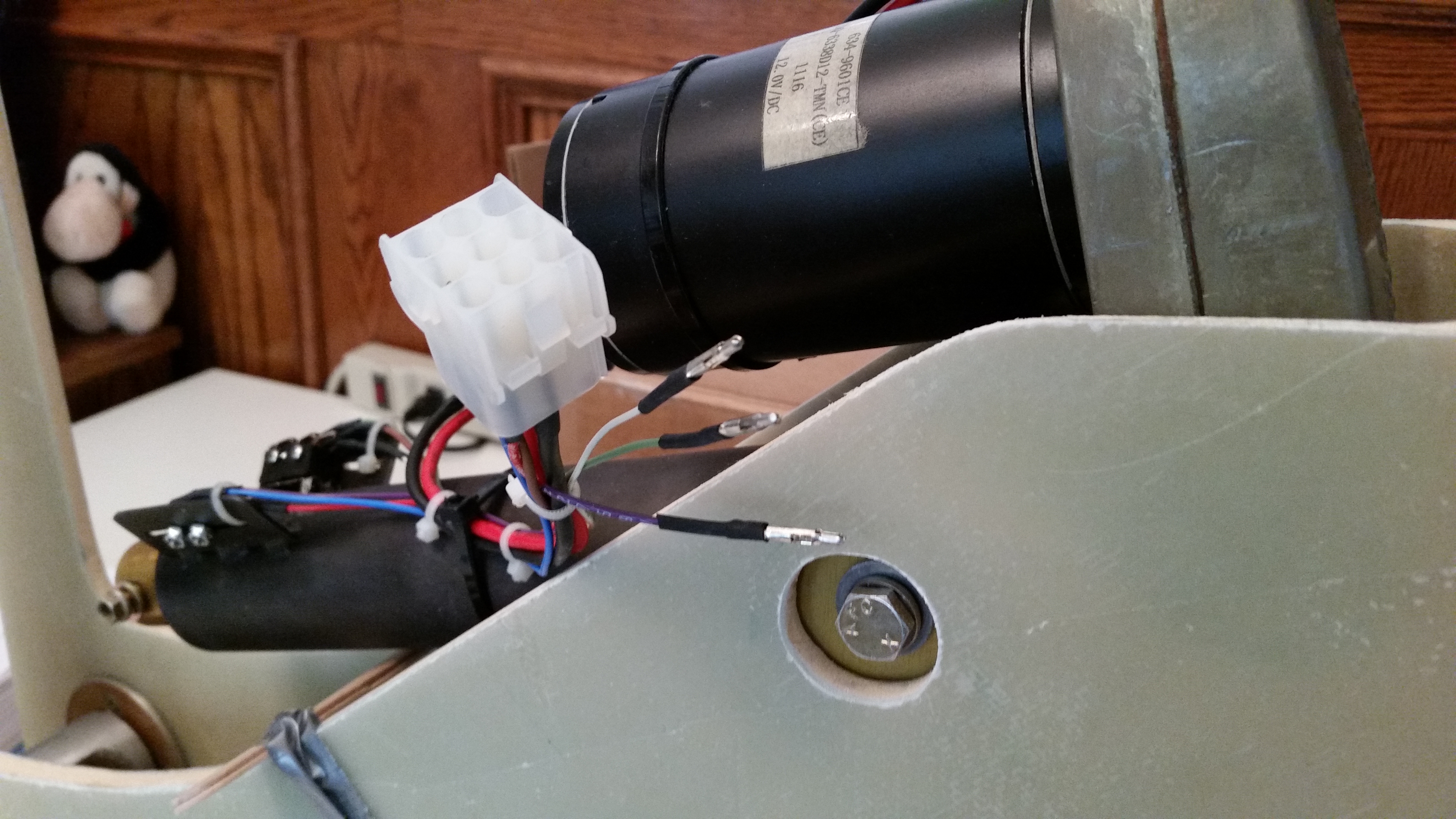
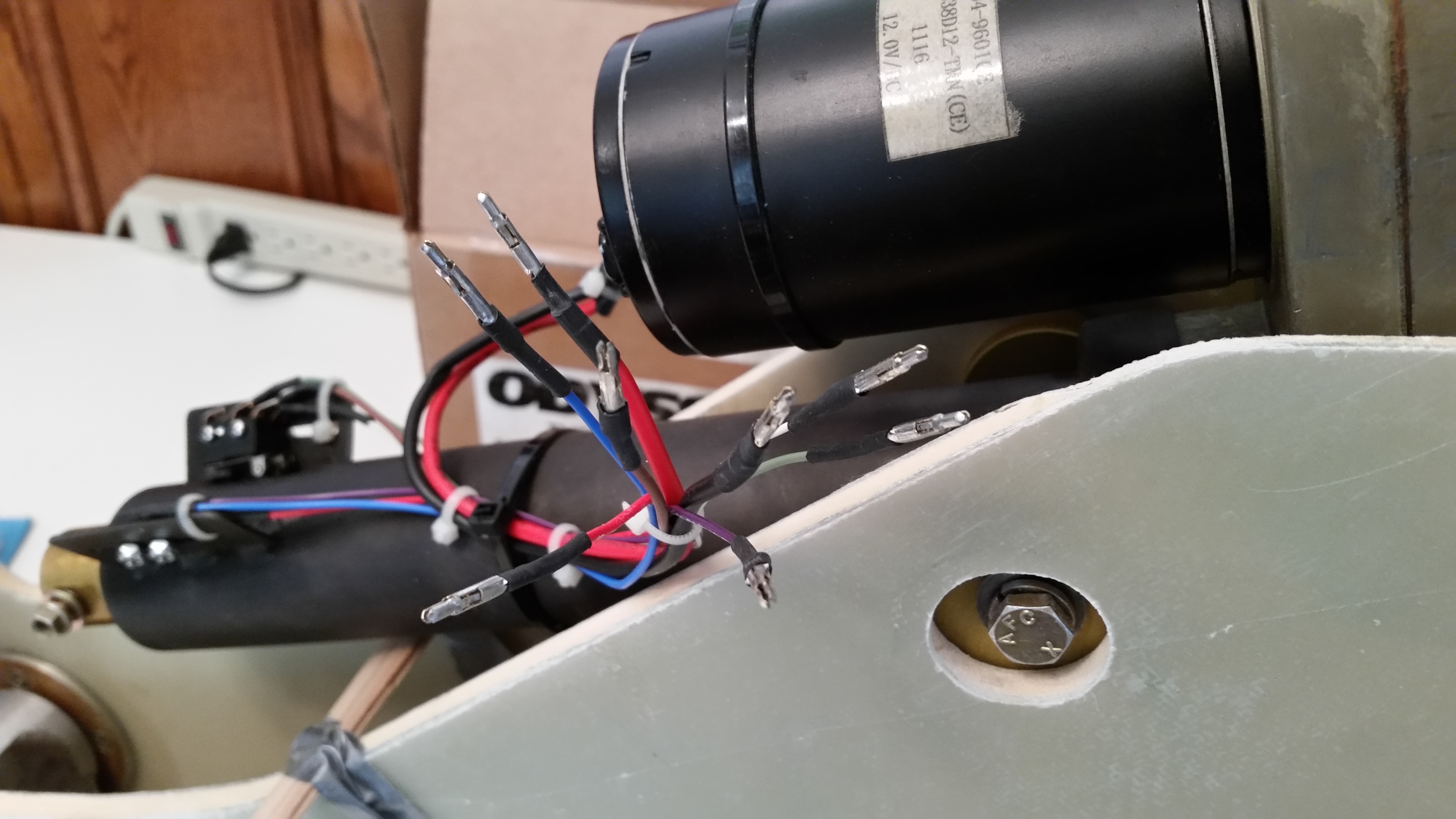
My first task was to pull off the motor side Molex connector, since I’ll be replacing it with an AMP CPC connector.

Removing gear actuator Molex connectorGear actuator Molex connector removed

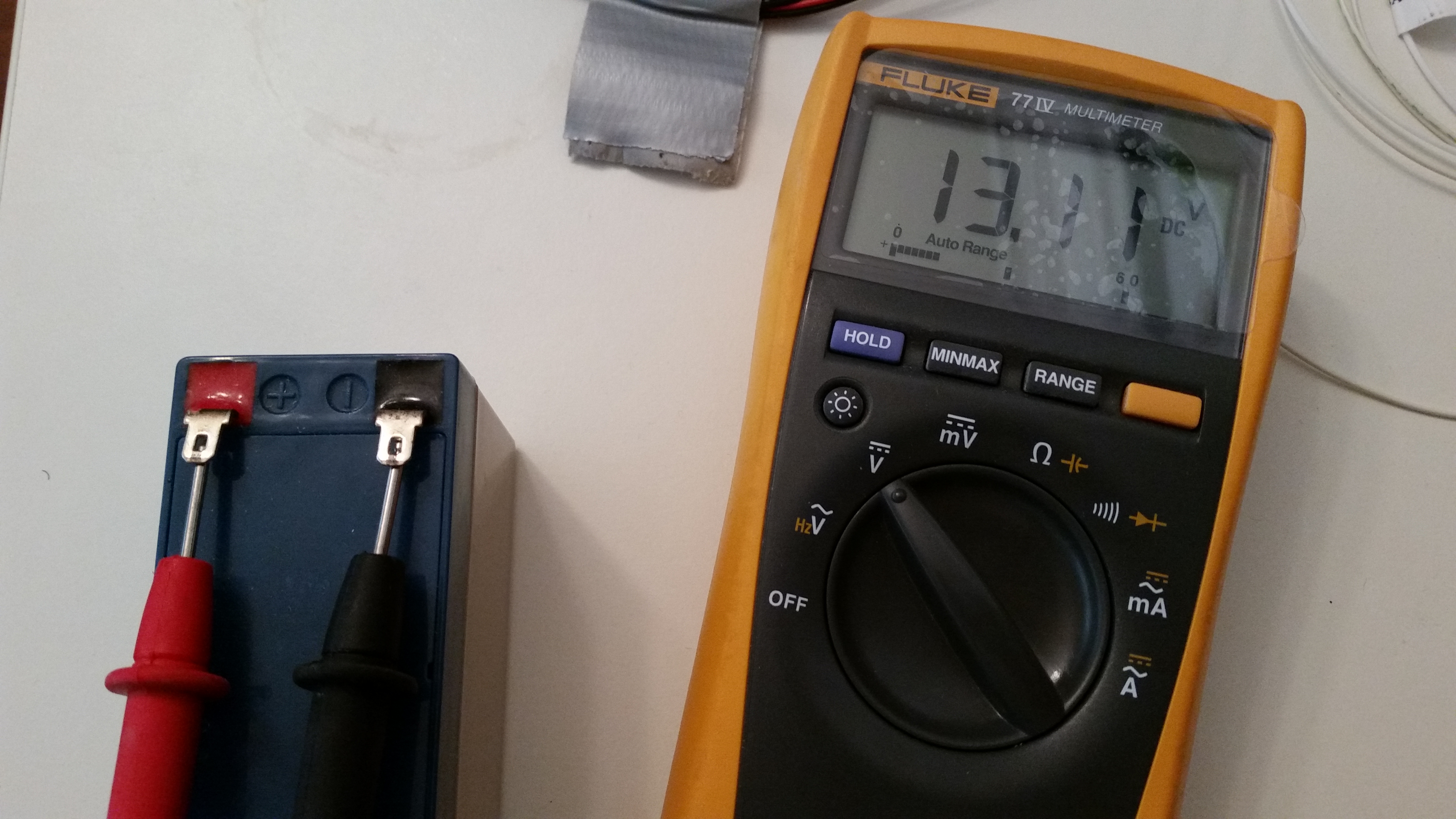
I then double-checked the charge on my nose gear back-up battery.  At 13.11V it looked good and seems to be holding its charge well.

Checking nose gear backup battery

While tracing out & connecting the wires for the nose gear actuator I was able to integrate & plan out the wiring for the gear & canopy warning module.  Basically, I figured out that I can use the up & down limiter “micro-switches” on the nose gear actuator to drive the warning signals to my gear/canopy warning module.  Of course the only issue is that I’ll need to order another AMP CPC connector.  No worries really, since I was going to have to do some finagling with the thick power wires to get them into the 9-pin AMP CPC connector.  A larger connector will be able to accommodate bigger wires.

After my webinar and playing around with the nose gear actuator wiring for a bit, I went back downstairs and vacuumed the foam before starting the layup.

Ready for glass

I then micro’d the top elevator surface.

Elevator micro'd

And laid up 2 plies of UNI at 30° in opposite directions.

Elevator top glassed

Since I used fast hardener I only had to wait about an hour before the layup was cured to a green stage.  I then razor trimmed the TE.

Top elevator TE trimmed

And then applied dry micro on the TE and covered it with peel ply.

Elevator TE micro'd

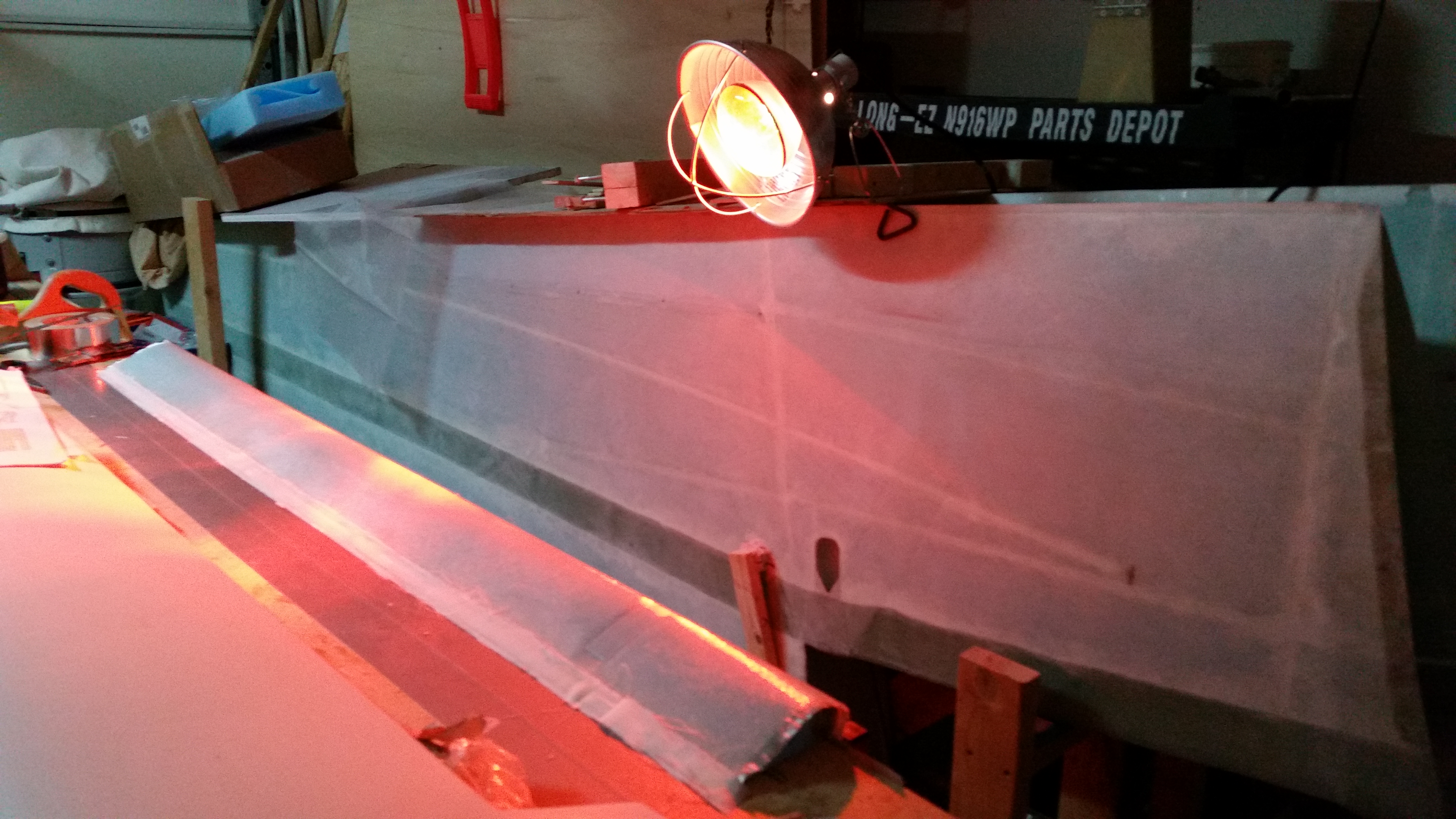
I turned on a heat lamp to help get this thing cured as fast as possible.

Putting the heat to the elevator

After watching some TV and working on this post for well over an hour, I then went down to the shop to check the elevator top skin layup.  It all looked good and was pretty much cured.  I carefully pulled the elevator away from the table mainly to keep the TE micro from securing the elevator permanently to the workbench and causing real mayhem if I had waited until tomorrow to pull it off the bench.

After pulling the foil tape off the elevator bottom I was ecstatic that the elevator bottom was SO clean & devoid of that Bondo crap that caused all the issues with the previous elevator! I couldn’t help but think how EZ this would have been had I known this trick back when I first built my elevators!

Elevator bottom

My next order of business was to cut away any stray LE glass overlap to keep any of the barbs-from-hell, that may have slipped past the peel ply, at bay.  I also cleaned the blobs of Bondo off the table.  Which thankfully came off fairly easily.

Elevator LE

After cleaning up the LE, I then pulled the peel ply from the outboard weight depression.

Elevator top skin cured

I then checked the contour again, only this time obviously with the top skin glassed.  Looking good!

Checking elevator contour

I then focused on the outboard elevator in order to prep that area for the 1-ply BID layup that it will receive.  I sanded the glass edges square and even with NC-6.

Elevator outboard end & NG6

I stood the elevator up on end & cut the foam to create a wedge shape near the glass for the flox corners.

Elevator end foam corners cut

I grabbed a piece of scrap BID and cut it to roughly fit the end of the elevator.

1-ply BID for elevator end

I then mixed up some epoxy with fast hardener, made some flox for the corners & some micro for the foam.  I then laid up the 1 ply of BID, trimmed the glass a little and let it cure.

Elevator end BID layup

Elevator end 1-ply BID layup

In a couple of hours I’ll check the layup and razor cut the edges.

Tomorrow I plan to finish the elevator rebuild by sanding the TE to its final shape and also attaching the outboard elevator weight.  Then it will just be a matter of cutting, drilling & cleaning up the hinge slots & bolt holes and the elevator rebuild will be complete!


Chapter 11 – Elevator Redo

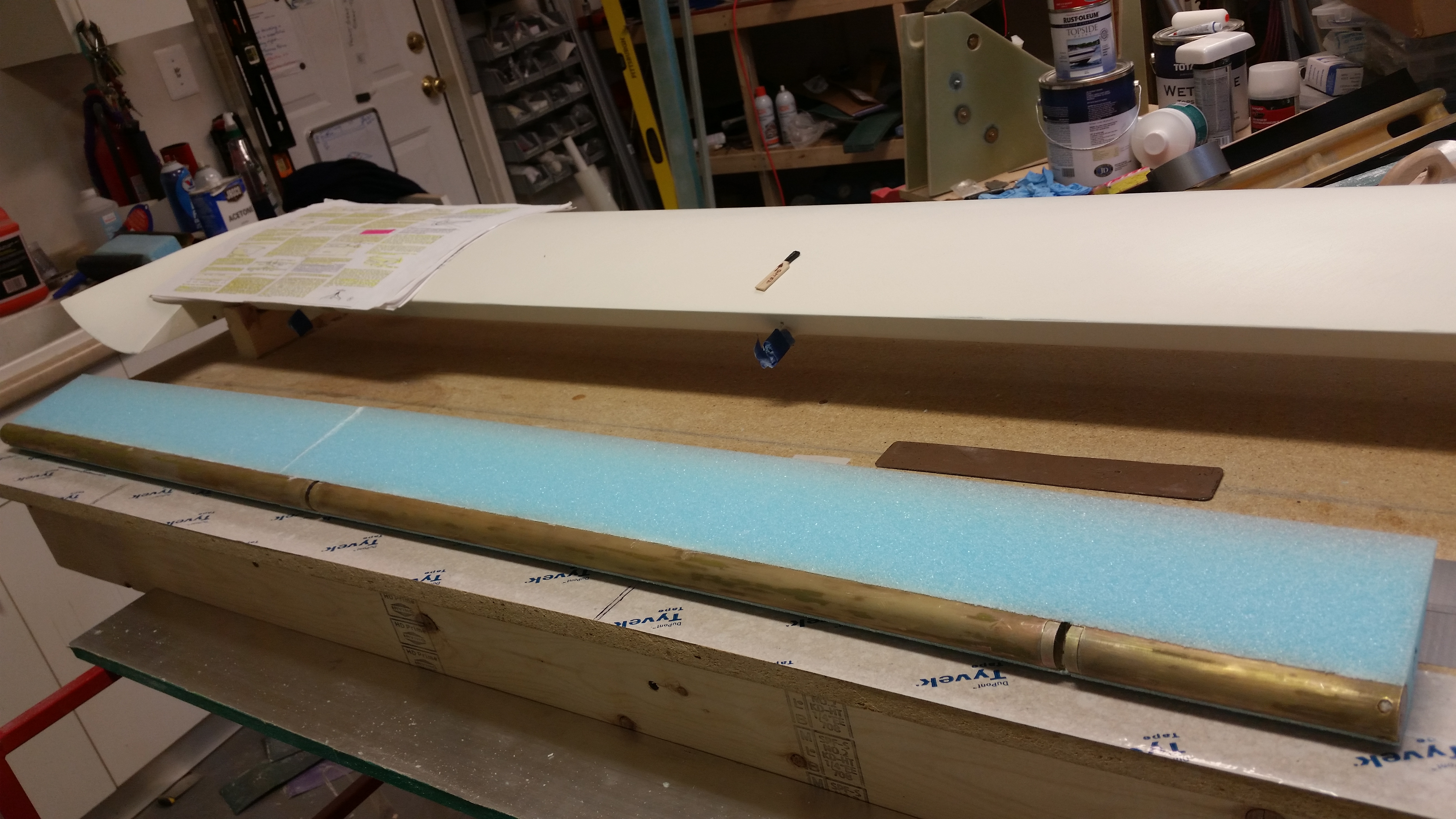
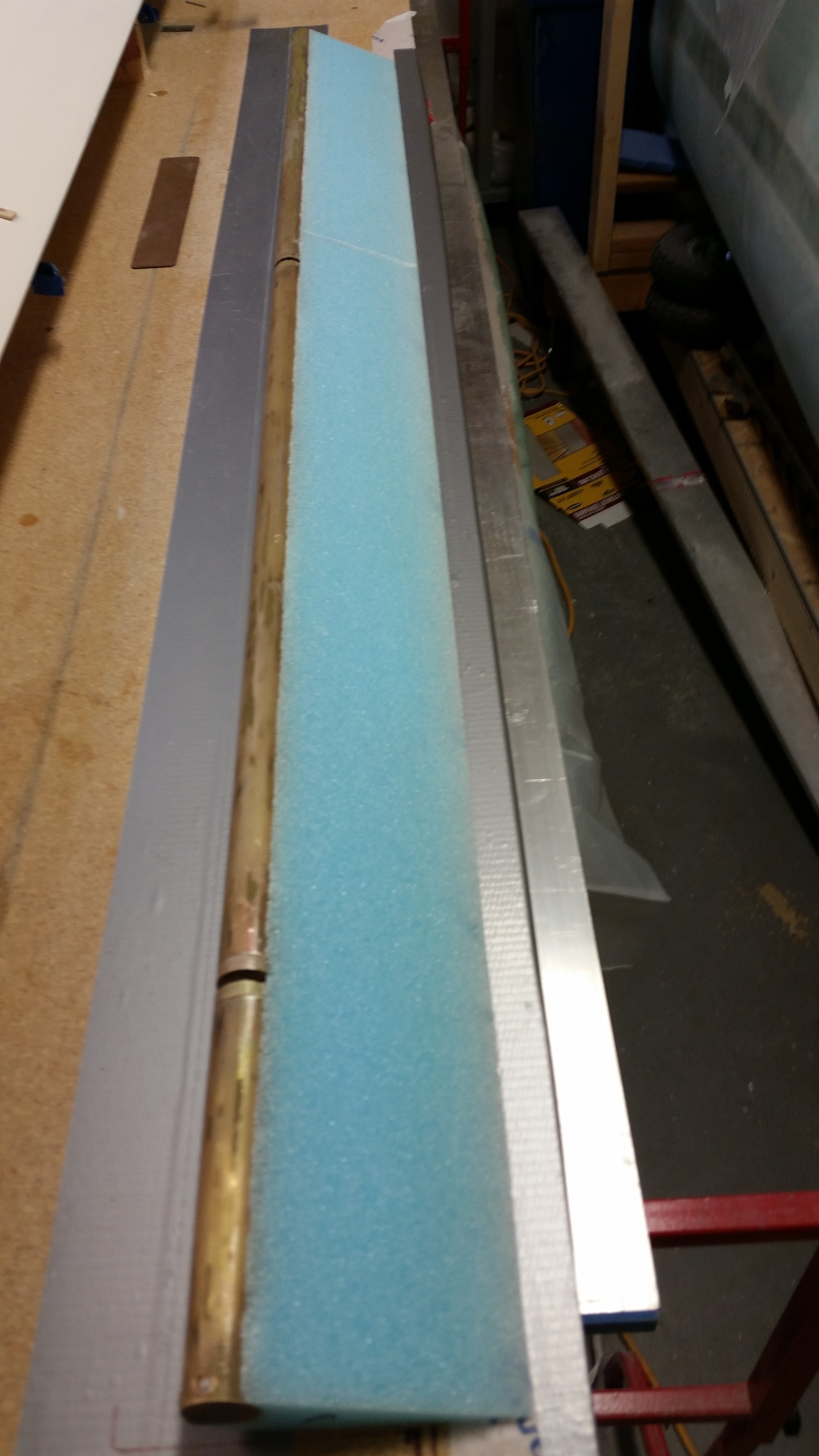
Today I focused entirely on the elevator.  Below is the elevator core micro’d to elevator tube.

Foam attached to tube

I prepped the tube by taping up the holes in the hinge pin hard points (NC2s) and the elevator tube end insert (NC6).

Prepping tube for glass

Before glassing the bottom skin I lightly sanded the bottom front edge of the foam core where it intersects with the elevator tube.  I also cleaned up the micro at the seam between the two elevator foam core pieces.

Elevator tube with new foam core

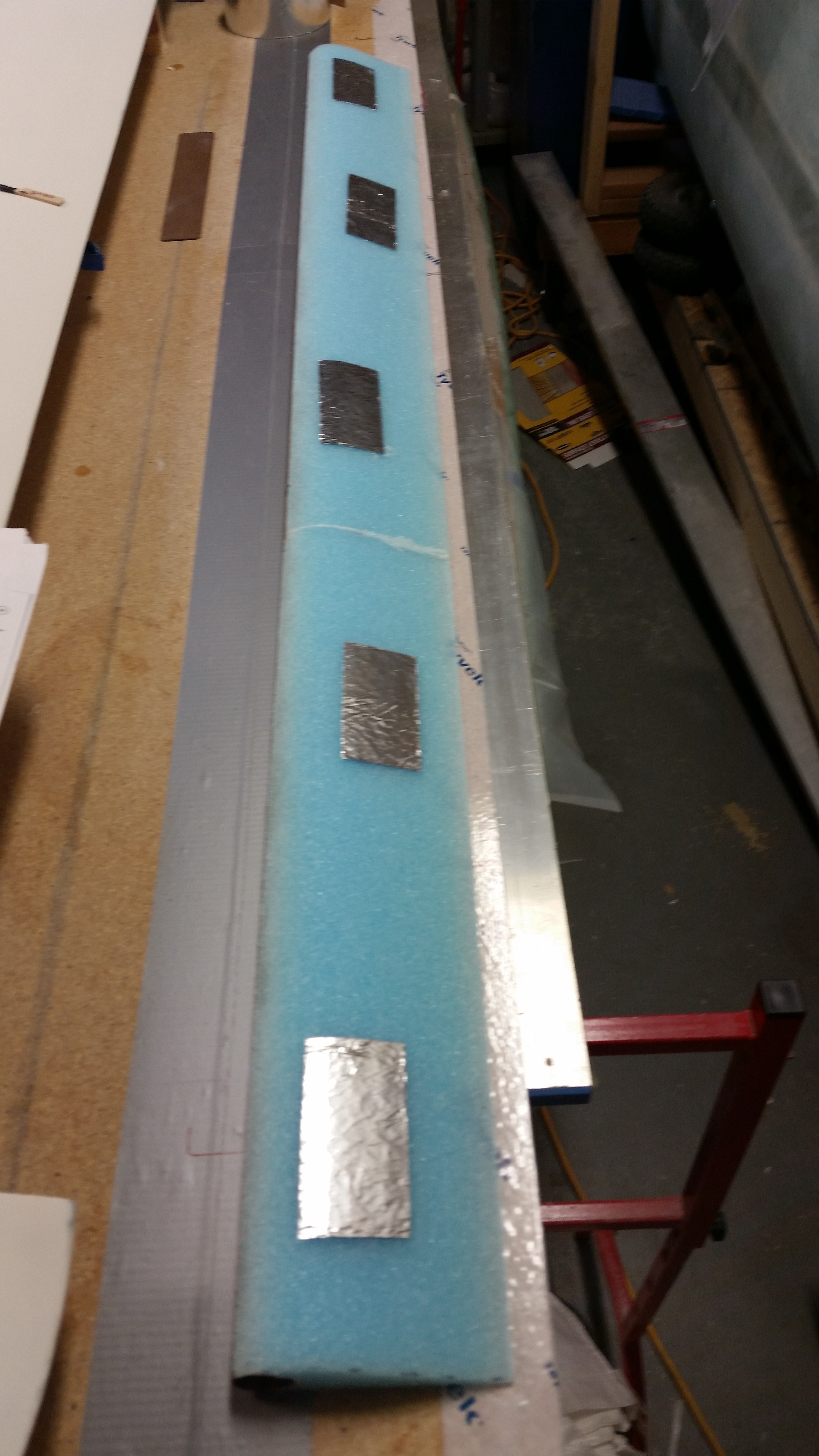
To minimize any damage to the foam surface, and thus minimize backfills to the foam, delams and in turn weight, I applied foil tape to the surface of the elevator top.  I figured I would try this method instead of applying 5 minute glue directly to the foam.

Foam preservation attempt!

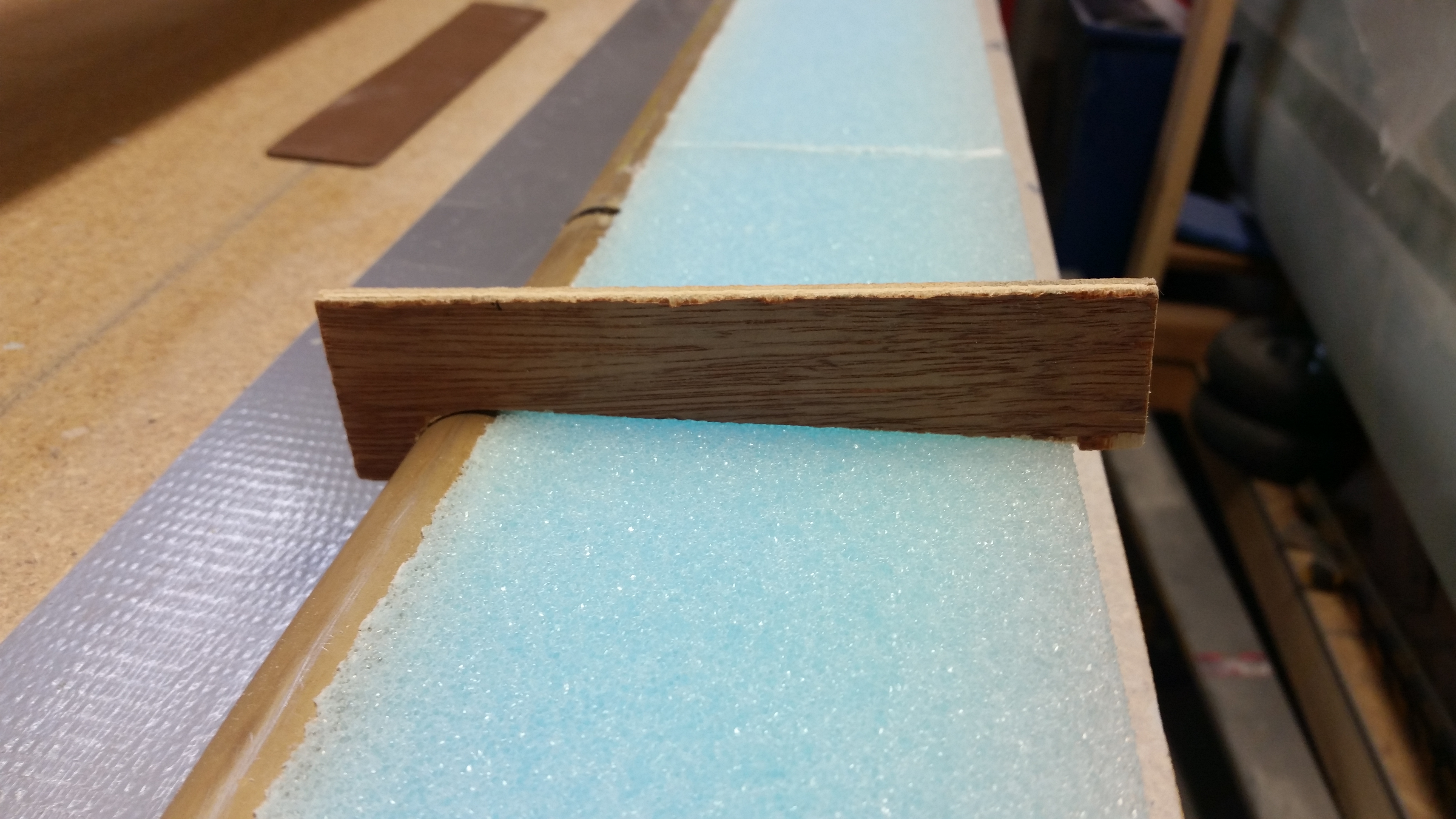
I then quickly checked the bottom contour of the elevator.

Double checking bottom profile

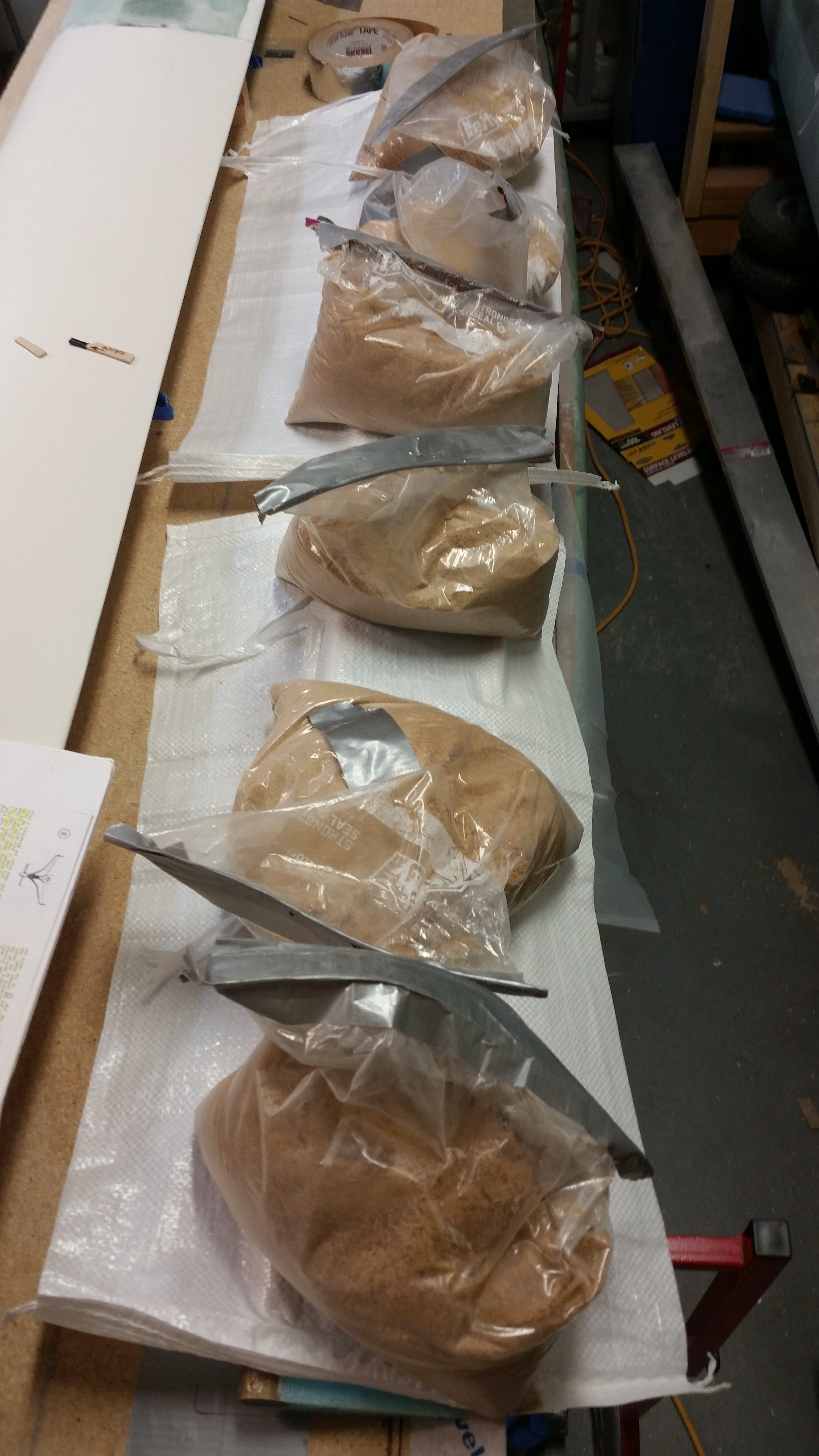
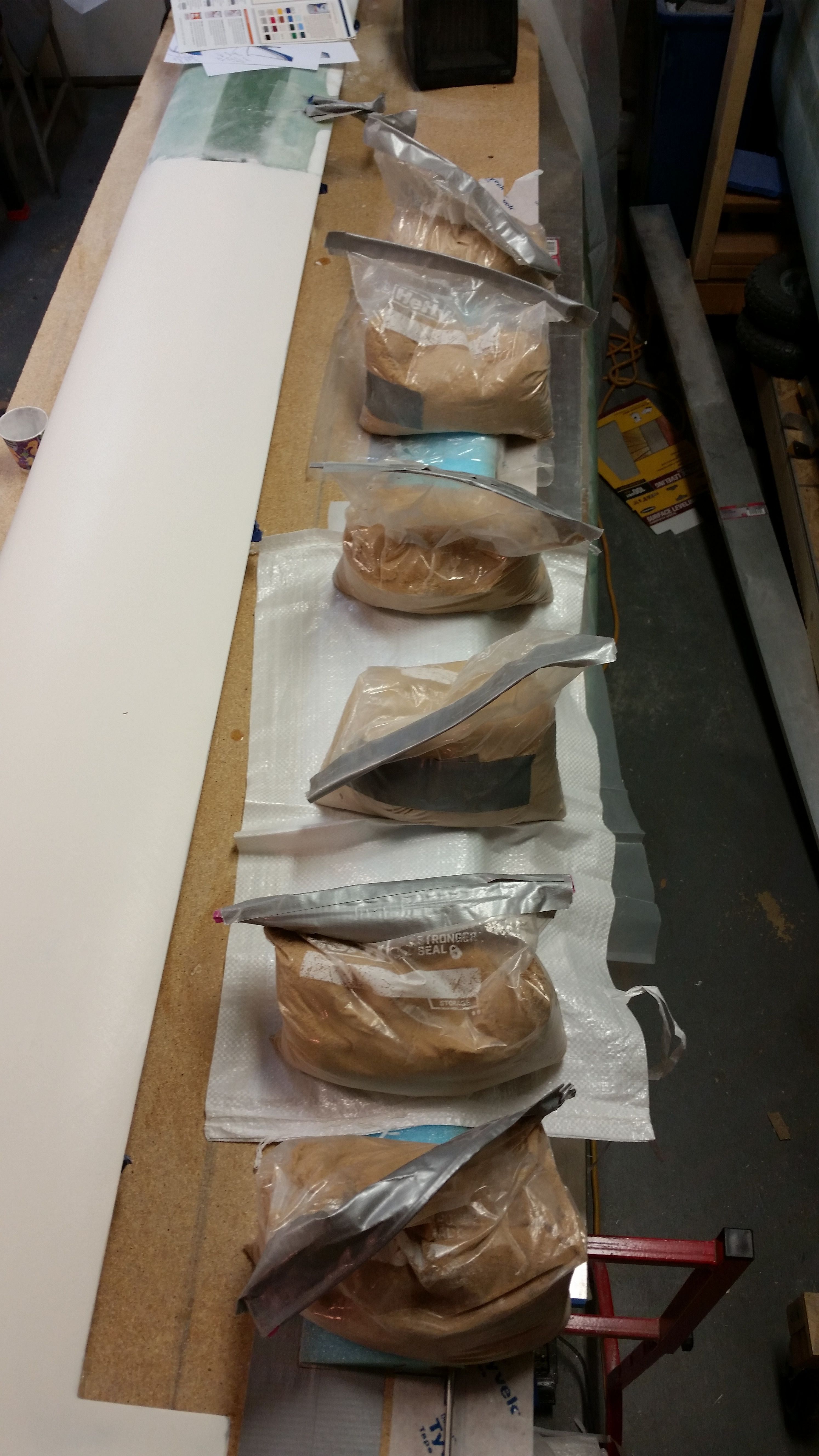
And then mixed up some 5 minute glue, applied a good sized drop to each piece of foil tape, and attached the inverted elevator core to the work bench.  I weighed down the TE with sandbags.

Weight on elevator during 5 min cure

After the 5-minute glue cured, I did a final check on the foam before I glassed it.

Elevator bottom ready for glass

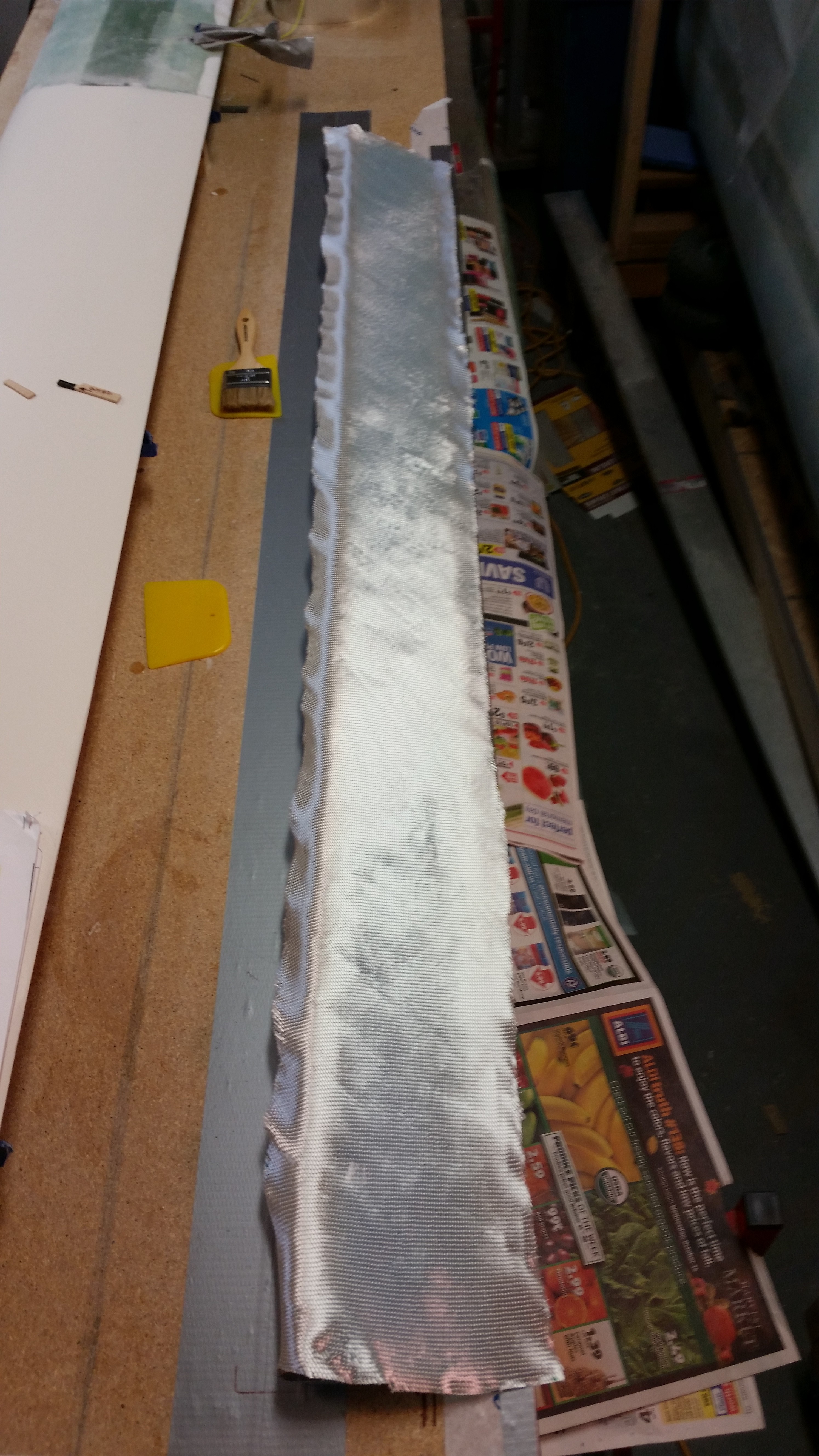
I also checked the UNI glass to ensure it fit.  I then glassed the lower elevator skin 2-ply UNI layup using fast hardener.

Checking glass fit

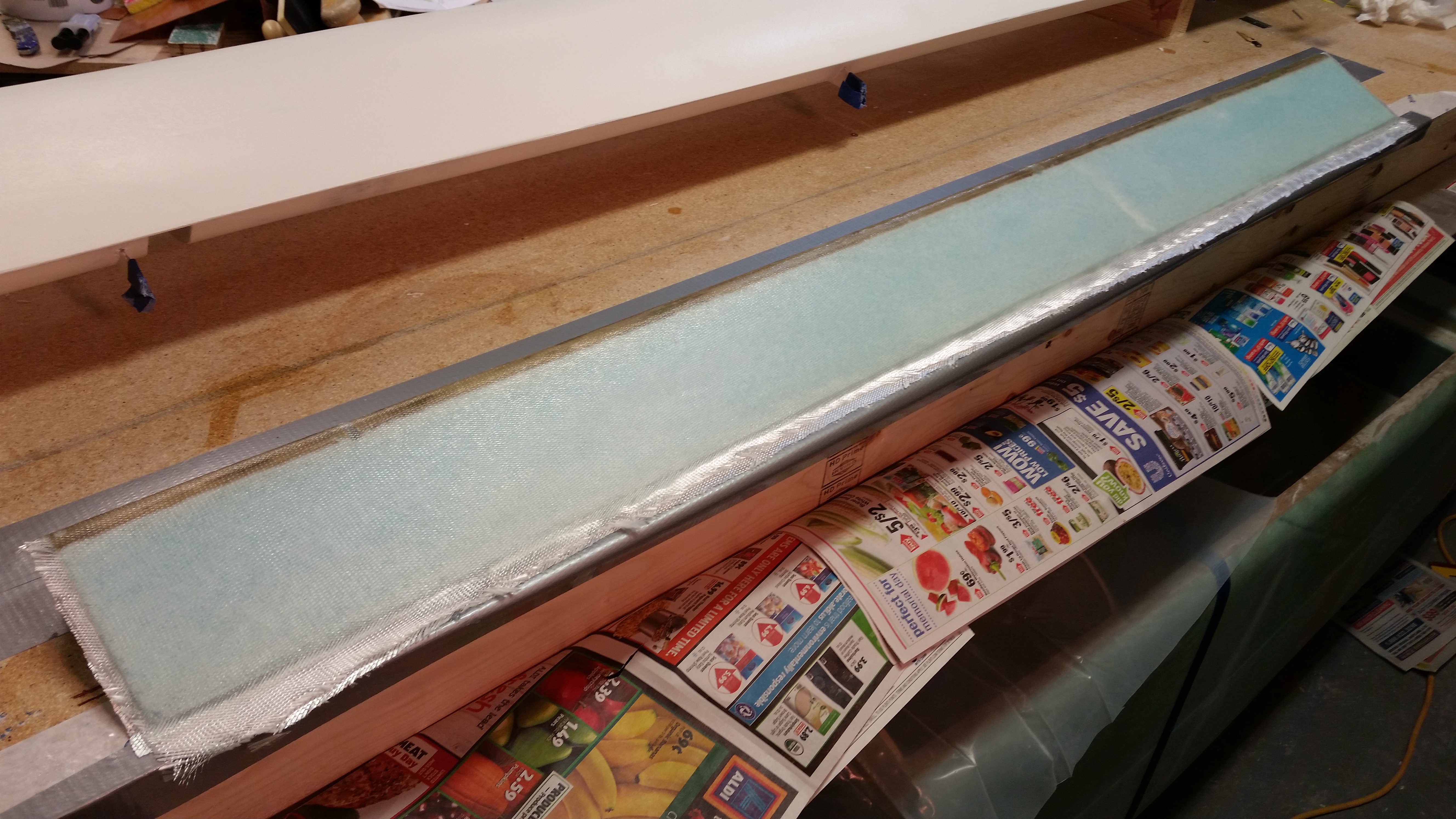
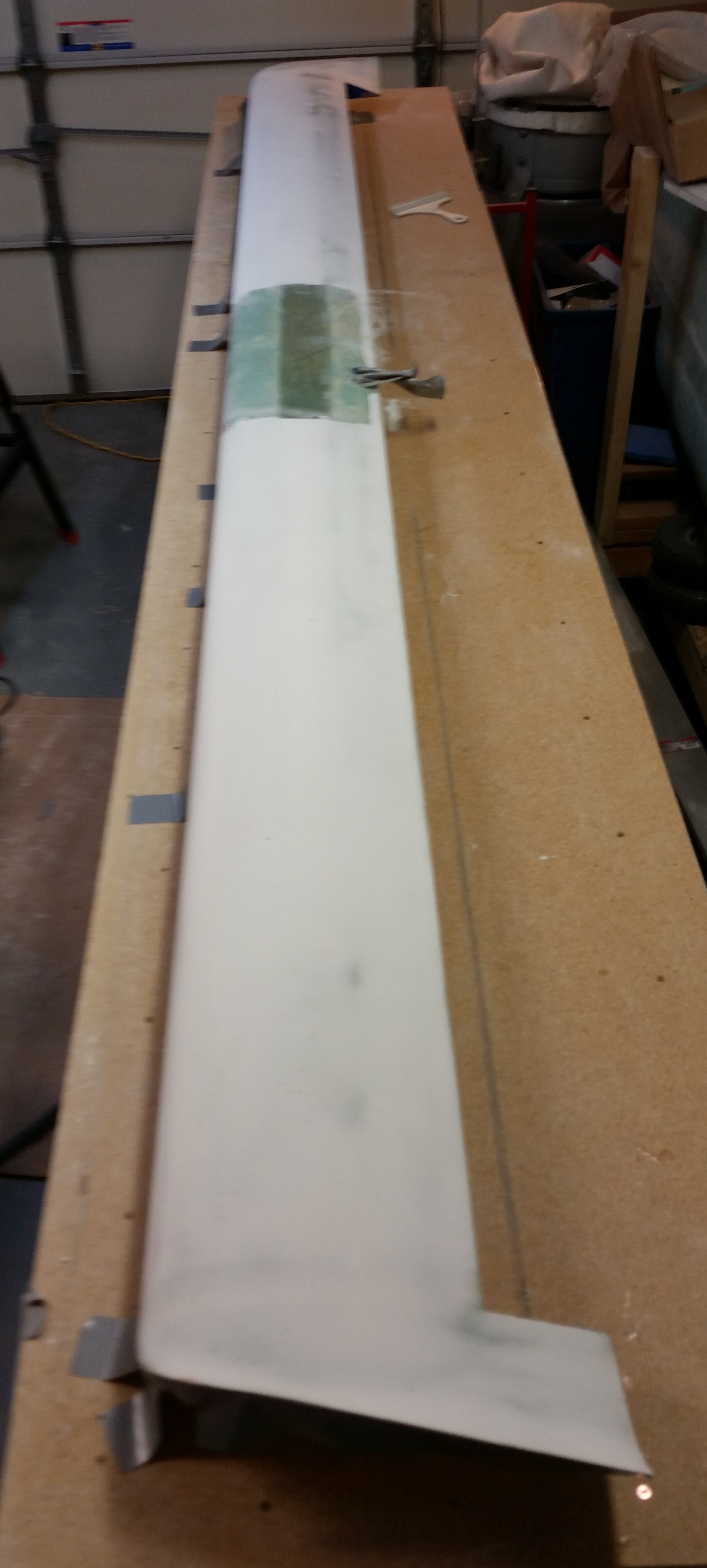
Here’s the (new) glassed bottom of the elevator.

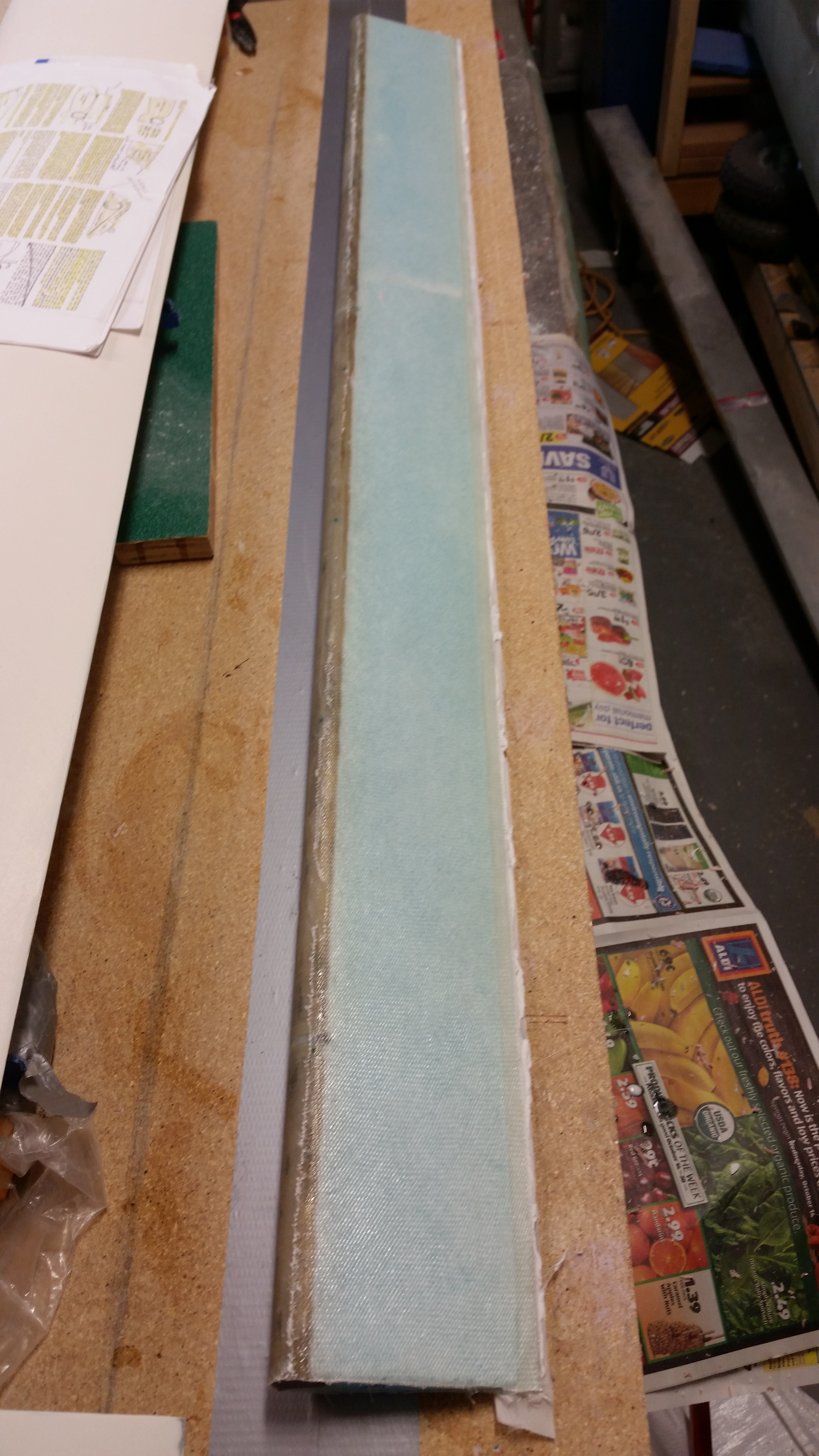
Cured bottom elevator skin

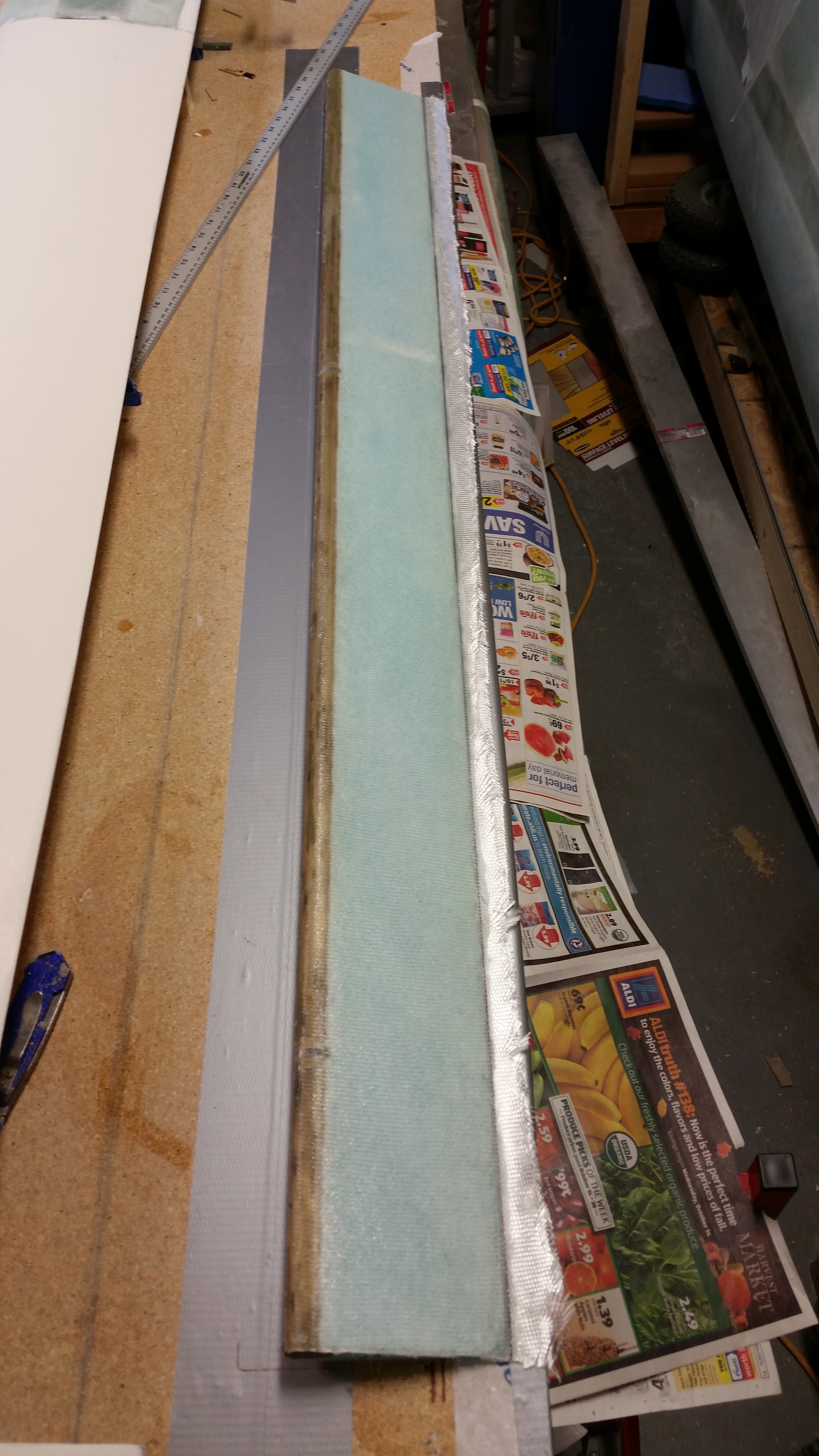
Here are some shots of the finished elevator bottom, in various stages of razor trimmed glass.

Cured bottom elevator skinCured bottom elevator skin

Cured & trimmed bottom elevator skin

I was going to glass the top skin of the elevator as well, but I went out to dinner tonight and it took forever to get our food, so I just didn’t make it back in time to fire up the Dremel tool to trim the TE in order to get good glass-to-glass contact between top & bottom skins.

Tomorrow I’ll prep the elevator & glass the top first thing, and if all works out I’ll actually get the outboard elevator end glassed as well.


Chapter 11, 13 & 22 – Tubing it…in a good way!

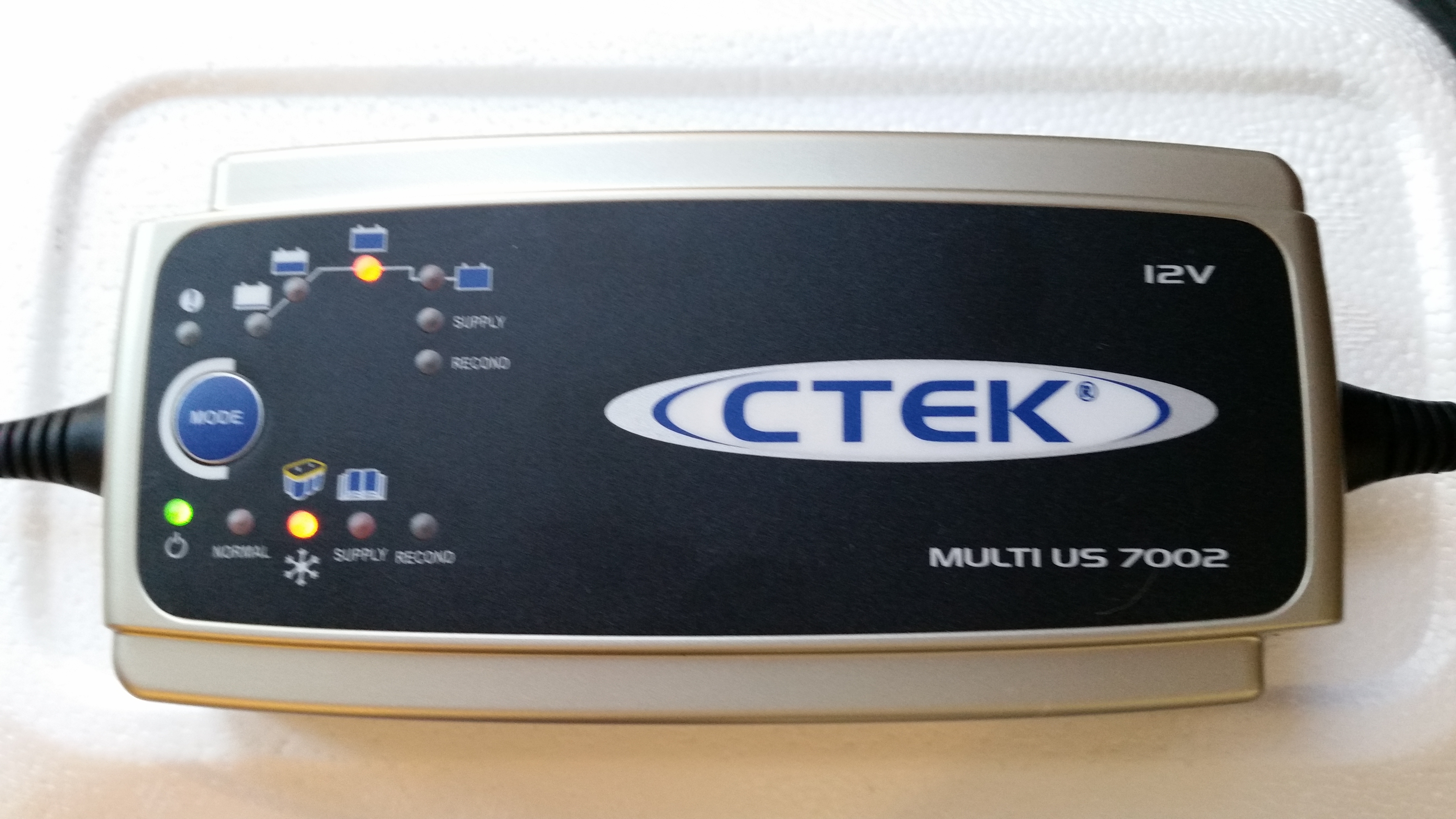
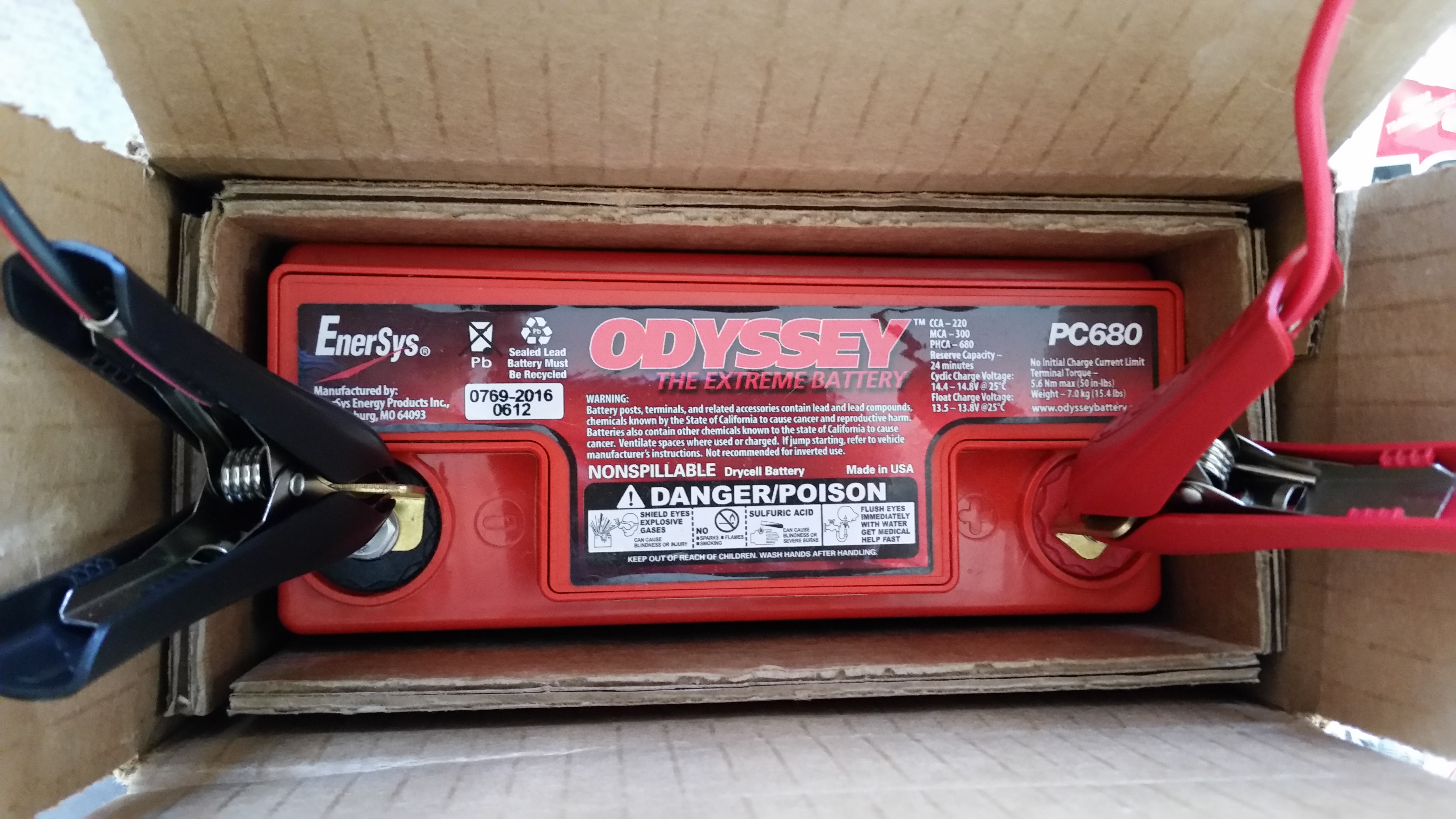
Today the UPS guy showed up with the battery charger I ordered from Amazon last week. I ordered this battery charger because in reading the manual for the Odyssey PC680 battery it stated that if the battery charge fell below 12.65 volts, than it needed to be charged before using it.  When I checked the battery the multimeter showed 12.57 volts, clearly below the threshold required to be able to use the battery as per the instructions.

Of course I knew I would need a battery charger eventually since the Odyssey PC680 is an Absorbed Glass Mat (AGM) type that is immune from acid spills and gas venting, and thus has some unique charging requirements to ensure the battery is maintained in an optimized state before it’s actual use in the Long-EZ.  An interesting side note to this battery is that it can be mounted in any position.

Currently, the main reason I want to use the battery is to test the nose gear actuator.  So when the battery voltage tested low I checked the Odyssey website for approved battery chargers.  After assessing a few battery chargers online, I decided on this one and ordered it.

Odyssey PC680 Battery Charger

I hooked up the battery to the new charger before heading out to a meeting I had at the office. Before I left for my meeting I went upstairs and changed clothes –about 5 minutes– and when I did a final check before walking out the door the charger had already completed its first 2 phases and was in the basic charging phase.  This was a good sign since the initial phases are conditioning cycles that bring a battery back to the point where it can simply be charged in phase 3, where again, my battery was before I even left the house.  By the time I returned about 2 hours later, the battery was fully charged and was at 13.87 volts.  Not bad!

I’m discussing the battery at this point since the short term use of the battery is to test the nose gear actuator (Chapter 13) while of course the long term use will simply be as the aircraft’s primary power source (Chapter 22).

Odyssey PC680 Battery

I then focused on the new elevator build.  I pulled the elevator tube out of the vinegar-filled PVC pipe and did a final clean on the tube.  I then washed down the elevator tube with Simple Green before taking it outside to Alodine it.

Final Cleaning Elevator TubeFinal Cleaning Elevator Tube

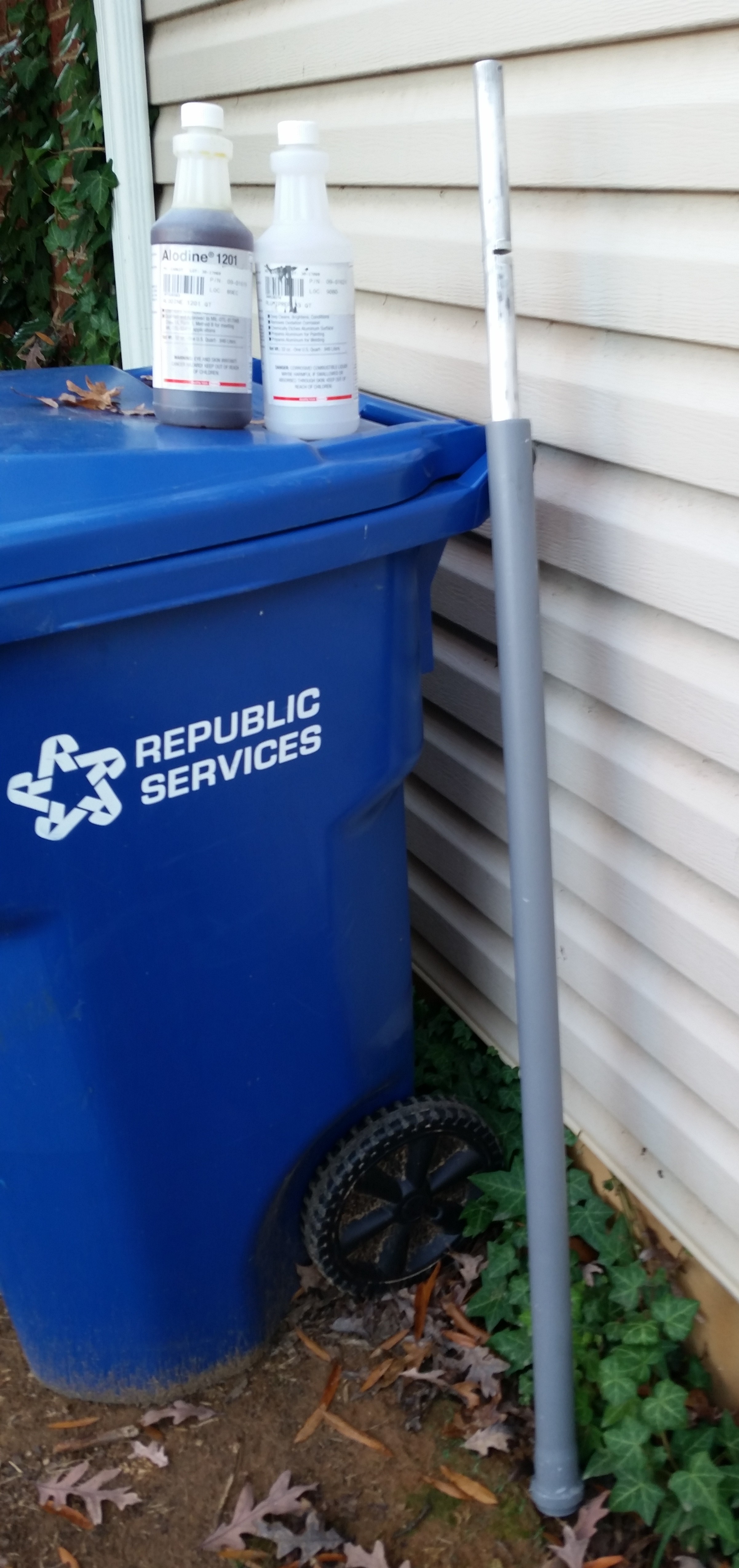
I washed out the PVC pipe, filled it full of Alumaprep, and then submerged all but about 18″ of the elevator tube into the Alumaprep.  Since my Alodine chemicals are weak, I left the tube in the Alumaprep for about 8 minutes before taking it out, rinsing it with water and giving it a good scrub.  I then put it back into the Alumaprep with the other end in first.

After the Alumaprep wash, I rinsed down the tube and did the same process in PVC pipe #2 filled with Alodine.  Again, I left it in there way longer than normal, about 8 minutes per side since the Alodine was weak.  After the time had passed, I again gave the whole tube a good rinse with clean water.

I hung the freshly Alodined elevator tube up to dry and then began to prep for micro’ing the elevator foam core to the tube.

Now, I was seconds away from taking a picture of the Alodined elevator tube when my long lost buddy Greg showed up.  Unfortunately when I loaded up all my pics at the end of the evening I realized I hadn’t taken the picture, which is unfortunate because I thought the Alodined tube turned out rather well.

Alodining Tube

As for the foam cores, since I ordered only the elevator cores from Steve at Eureka CNC, he could only send me the cores cut in half for shipping purposes.  The pics below are shots of one elevator core cut in half.

Elevator cores

Elevator core halves

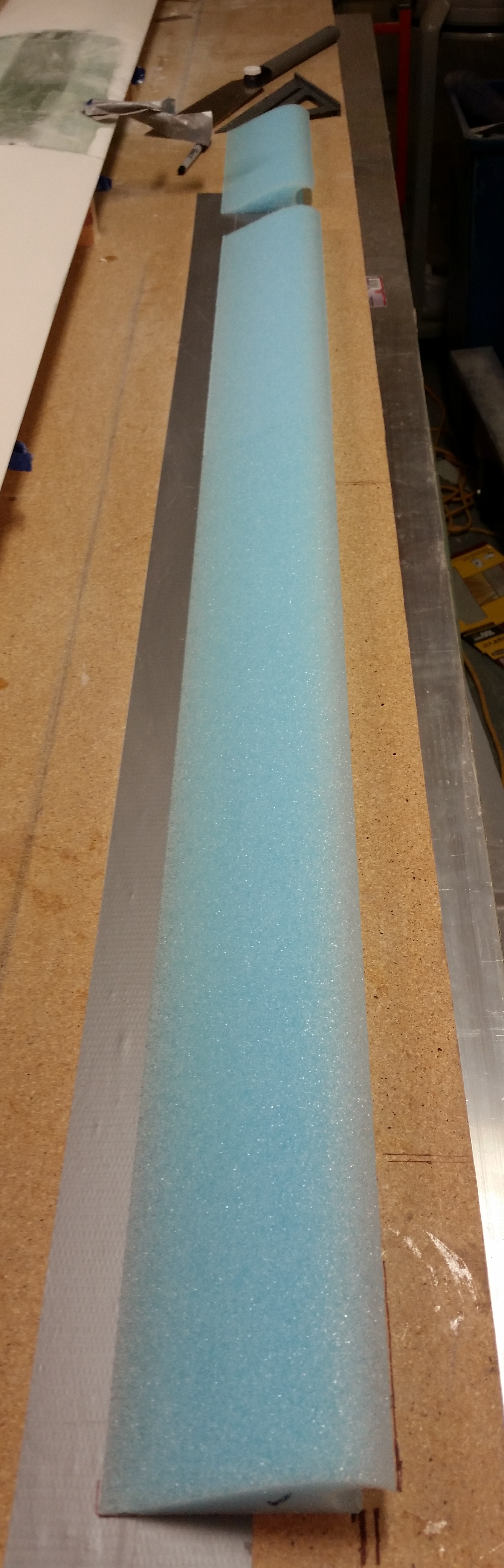
Here are the two halves end to end.

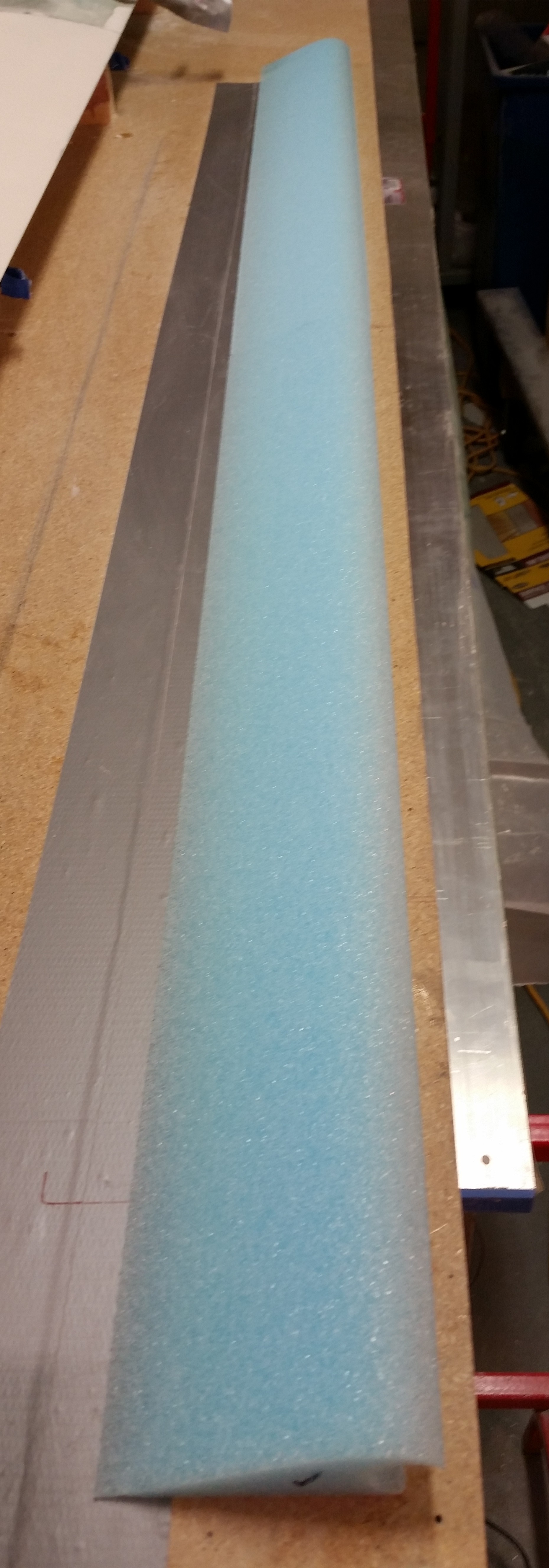
Elevator core

I marked the second elevator foam core piece to cut to length, making the total combined length of these elevator foam core pieces 53″ to match the length of the elevator tube.

Cutting elevator core to length

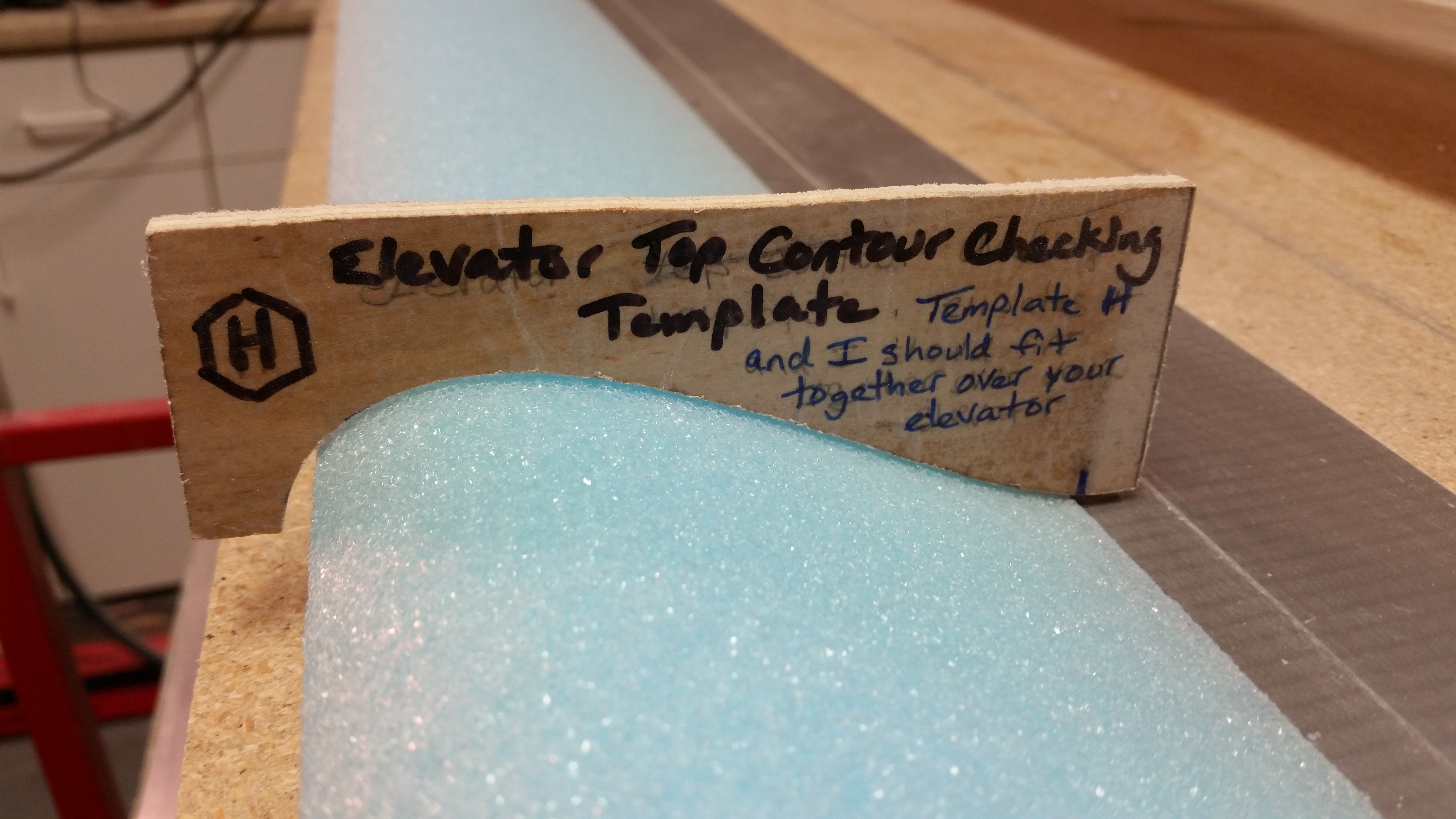
I then did a quick check of the top elevator contour with template “H” and it looked good.

Quick check of contour

Here’s a pic with the elevator core pieces cut to the proper 53″ length. [Note: these are the correct length of MY elevator cores for this airplane, since I widened the fuselage at all the bulkheads, my F22 & F28 are just a hair wider than the stock plans dimensions.  This widened fuselage resulted in slightly shorter elevators.]

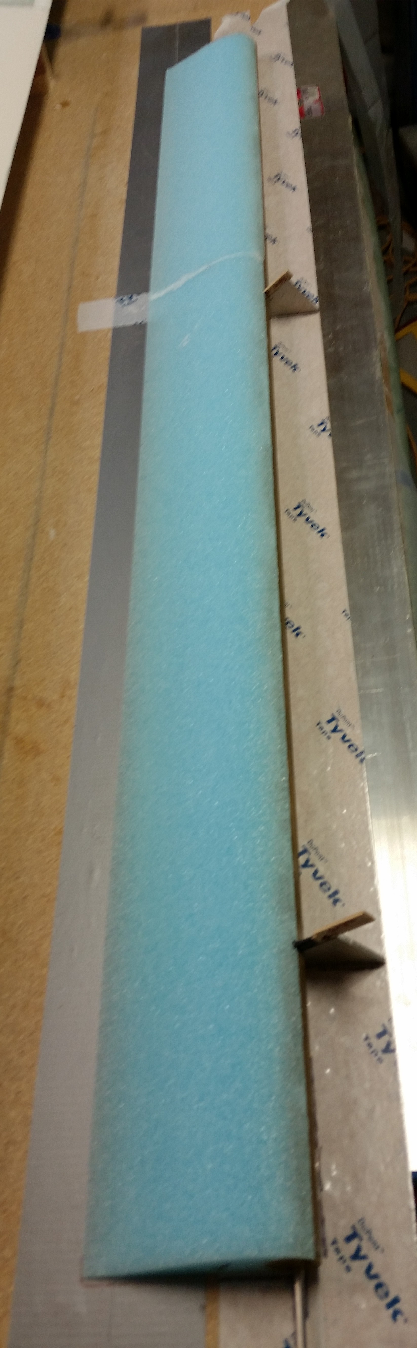
Elevator core cut to length

And here’s the two elevator core pieces micro’d to the elevator tube.  Yes, the elevator reconstruction is under way!

Elevator foam micro'd to tube

As per plans I weighed down the elevator core & tube with sandbags to keep them firmly in place.

Sandbags on micro'd elevator foam

Tomorrow I plan to glass the bottom skin, and possibly the top skin, of the elevator.


Chapter 11 & 25 – Cleaning the Tube

After a meeting I had in the office earlier today I ran over to Maryland to pick up a different brand of boat paint.  I’m going to do some tests and will report back on the entire plan later on.

Upon returning home I took the elevator tube out of the PVC tube filled with white vinegar and flipped it over to get the untouched 25% into the vinegar.  I cleaned off the majority of gunk with paper towels, then grabbed my razor knife and started cleaning off the dead glass.  I got as far down as the second hinge hardpoint (NC2).

Elevator tube - foam gubersElevator tube - dead glassElevator tube - Initial clean

After getting as much of the soaked dead glass off the tube as possible, I set the elevator tube back into the PVC tube filled with vinegar to soak.

Elevator tube soaking

After I put the elevator tube back in the vinegar cleaning solution, I then sanded the canard surface starting with 80 grit on the long board, and then switched to 120 grit on the long board as well.  I then switched to 150 grit paper and hand sanded each swoosh tip.

I was still getting a fair amount of residue on the sandpaper and had to clean it off the paper at regular intervals.  After going through another few sheets of very expensive long board sandpaper (although tonight was much better than last night as far as residue buildup), I decided to wait until tomorrow to finish sanding the top of the canard after it’s cured just a bit more.

In addition, I’m going to hit the canard with another couple coats of primer of the new boat paint.  I can tell already that this new primer is much more high build than my current primer, and of course you always need a good base of primer preferably of the same brand.  In light of this, I really want to get this primer sanded down to where the canard shape is as close to final as possible, and then smoothed out even more once the new primer is applied.

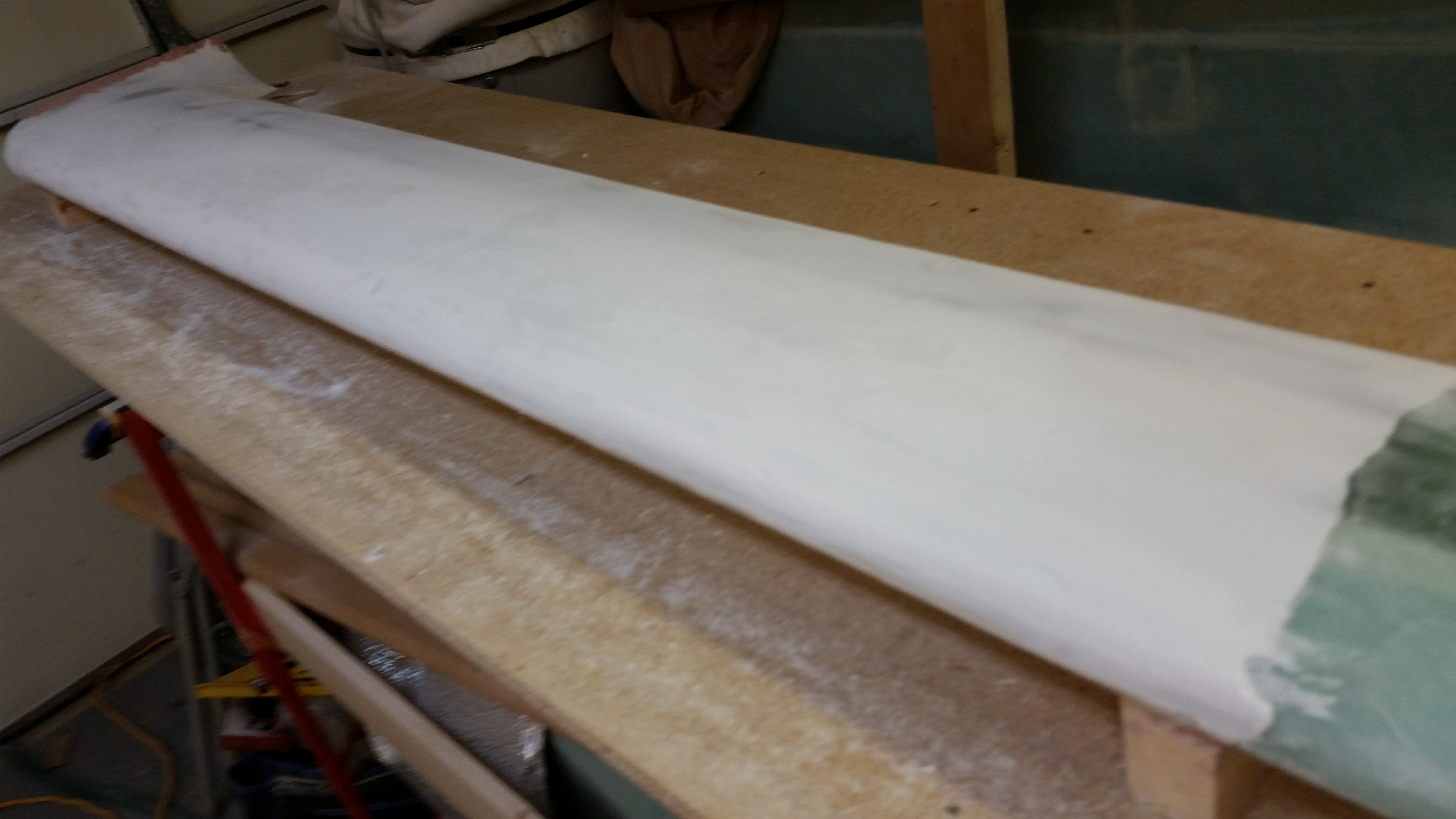
Sanded primer - Round 2 of 3

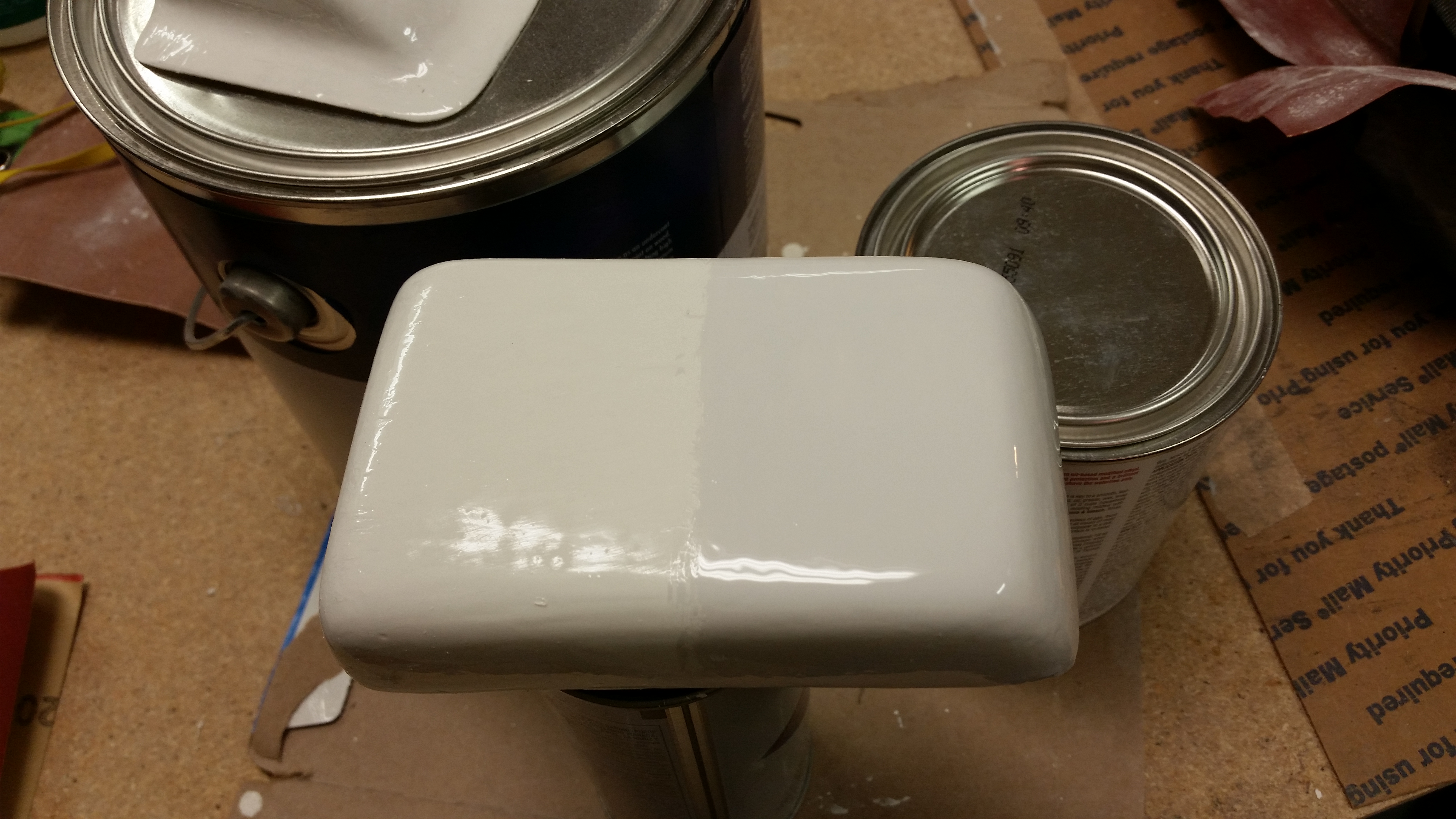
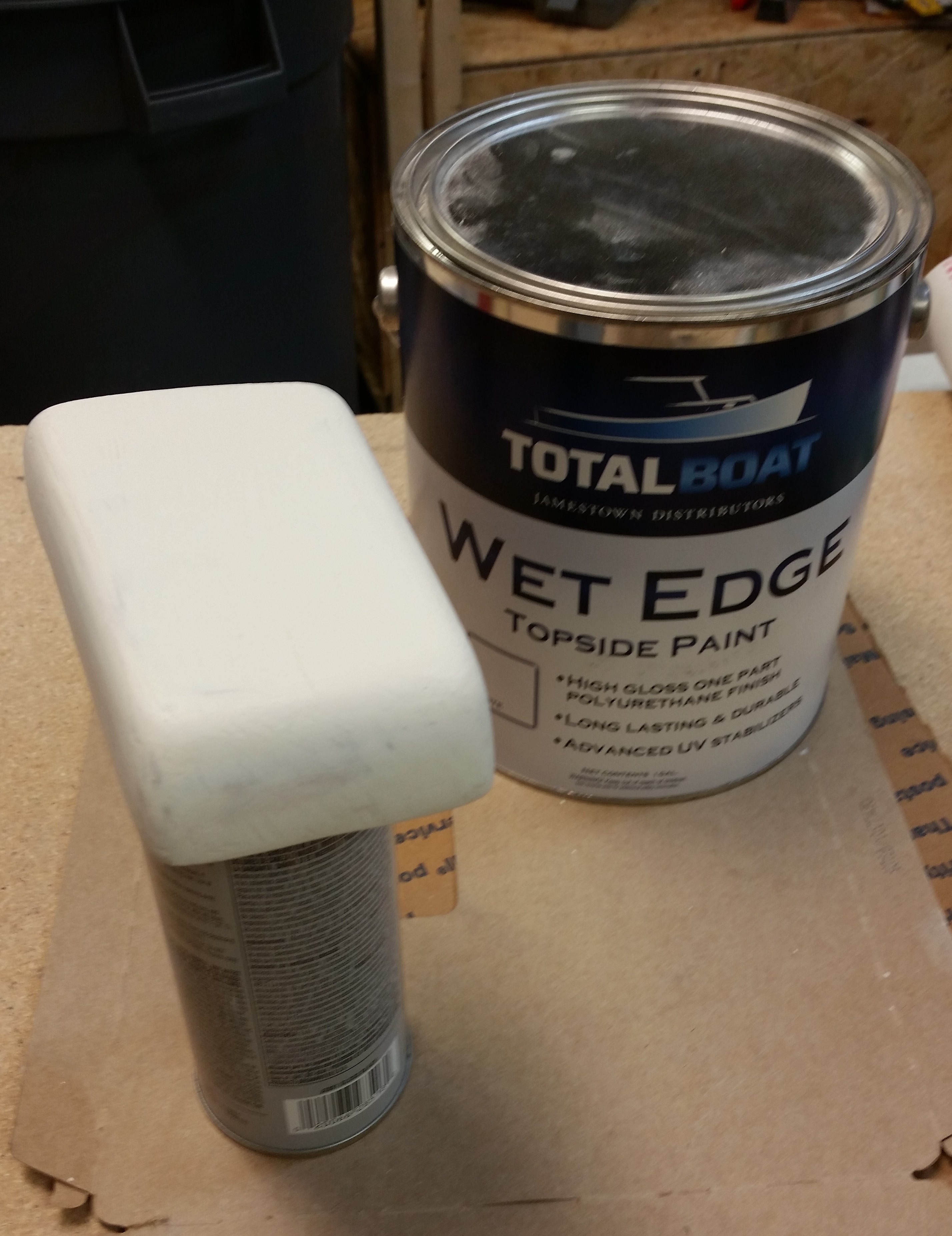
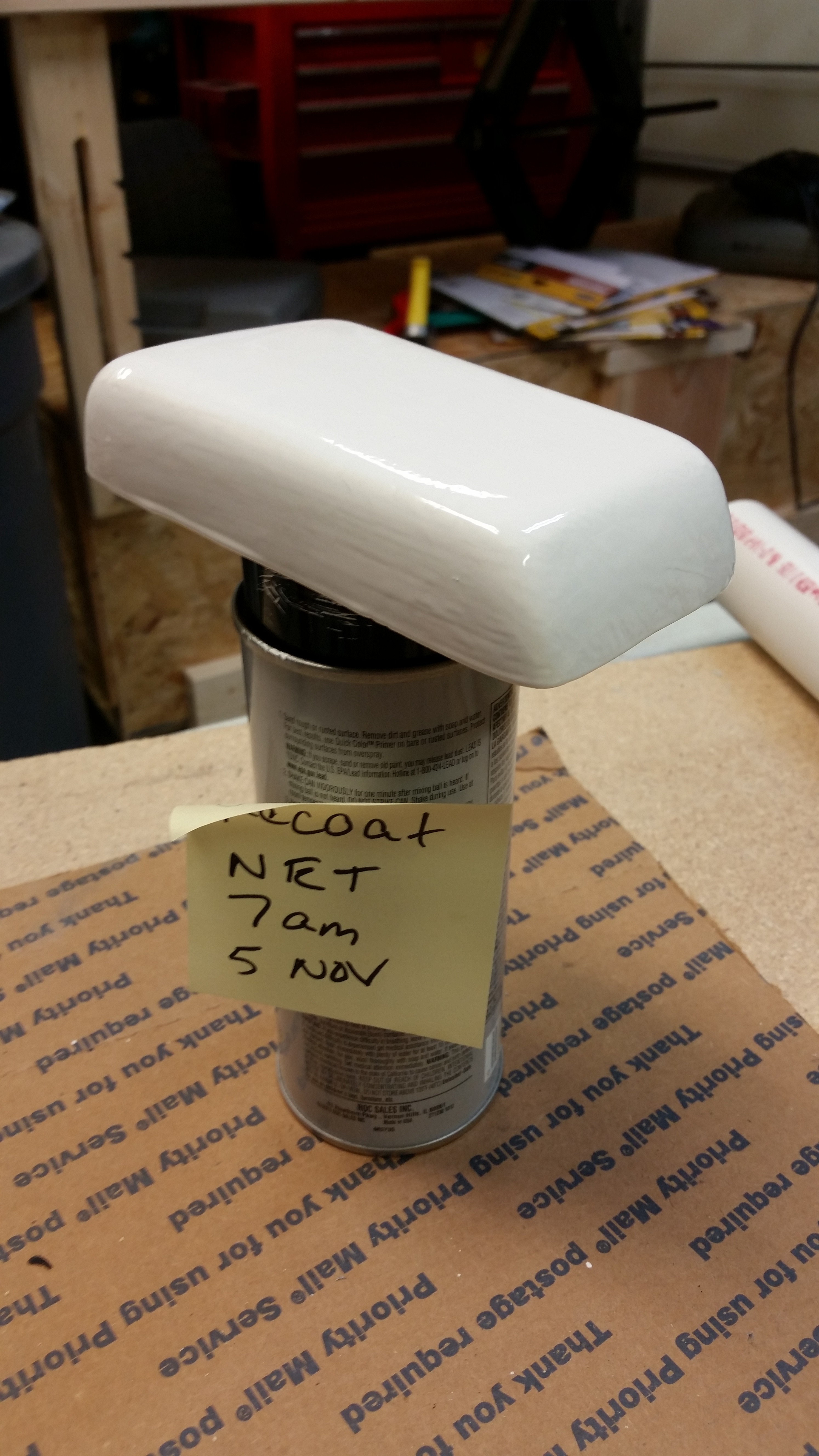
I then broke out the new paint to try it out.  As I said before as I was looking at the actual color of the white boat paint I had ordered before, in contrast with the white label on the gallon can and a standard white piece of paper, it clearly looked off white.  To compare and contrast the new paint I sanded down half of the headrest GPS antenna cover with 220 grit paper, and then painted it with the new paint.  I have to say that A) the new boat paint went on much easier and laid down much better than the old boat paint, and B) the new paint seems to have more of a “blue” hue vs a “yellow” hue, as you can see below. The bottom line is that the new paint is simply whiter, in my opinion.

New paint

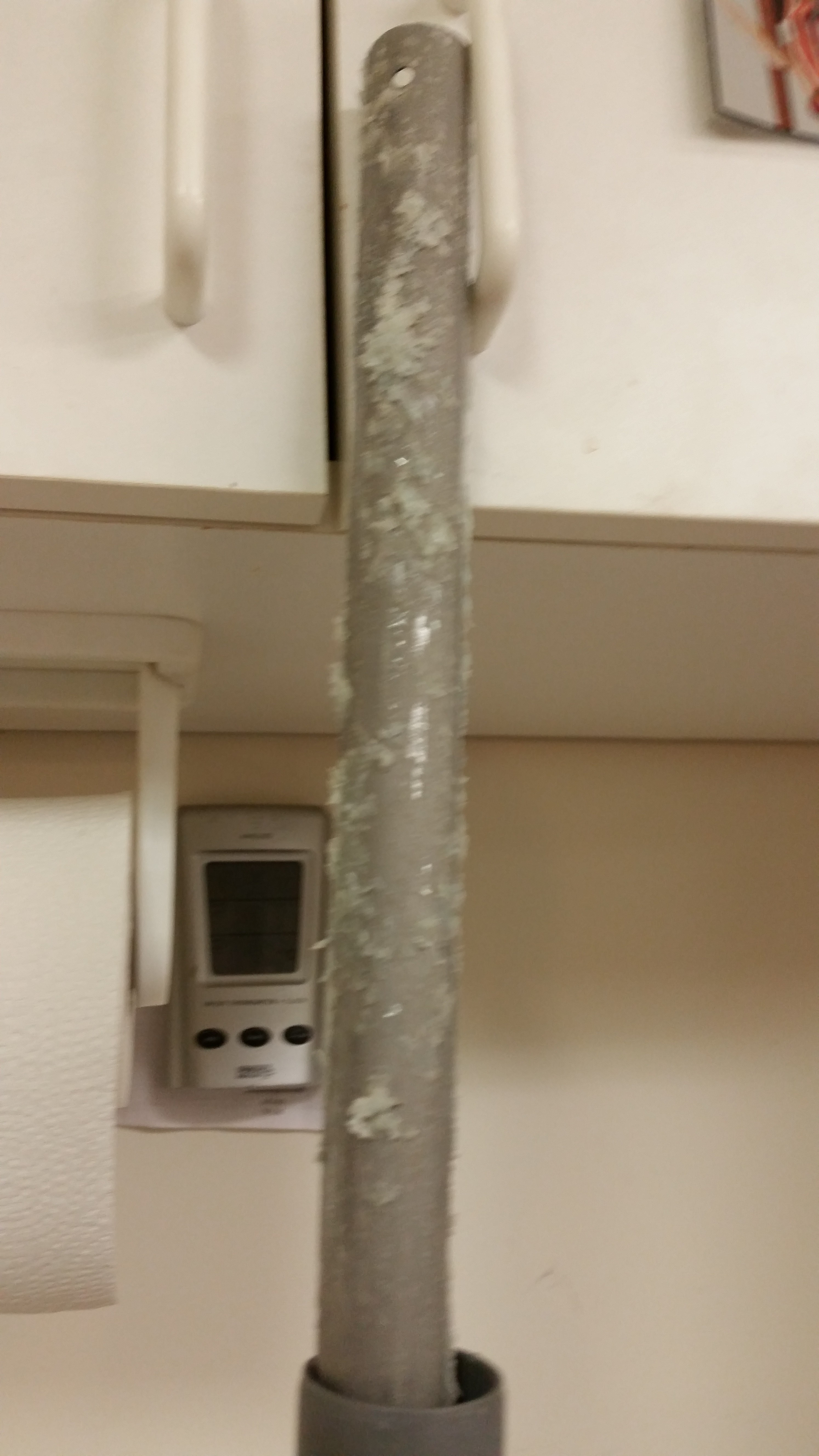
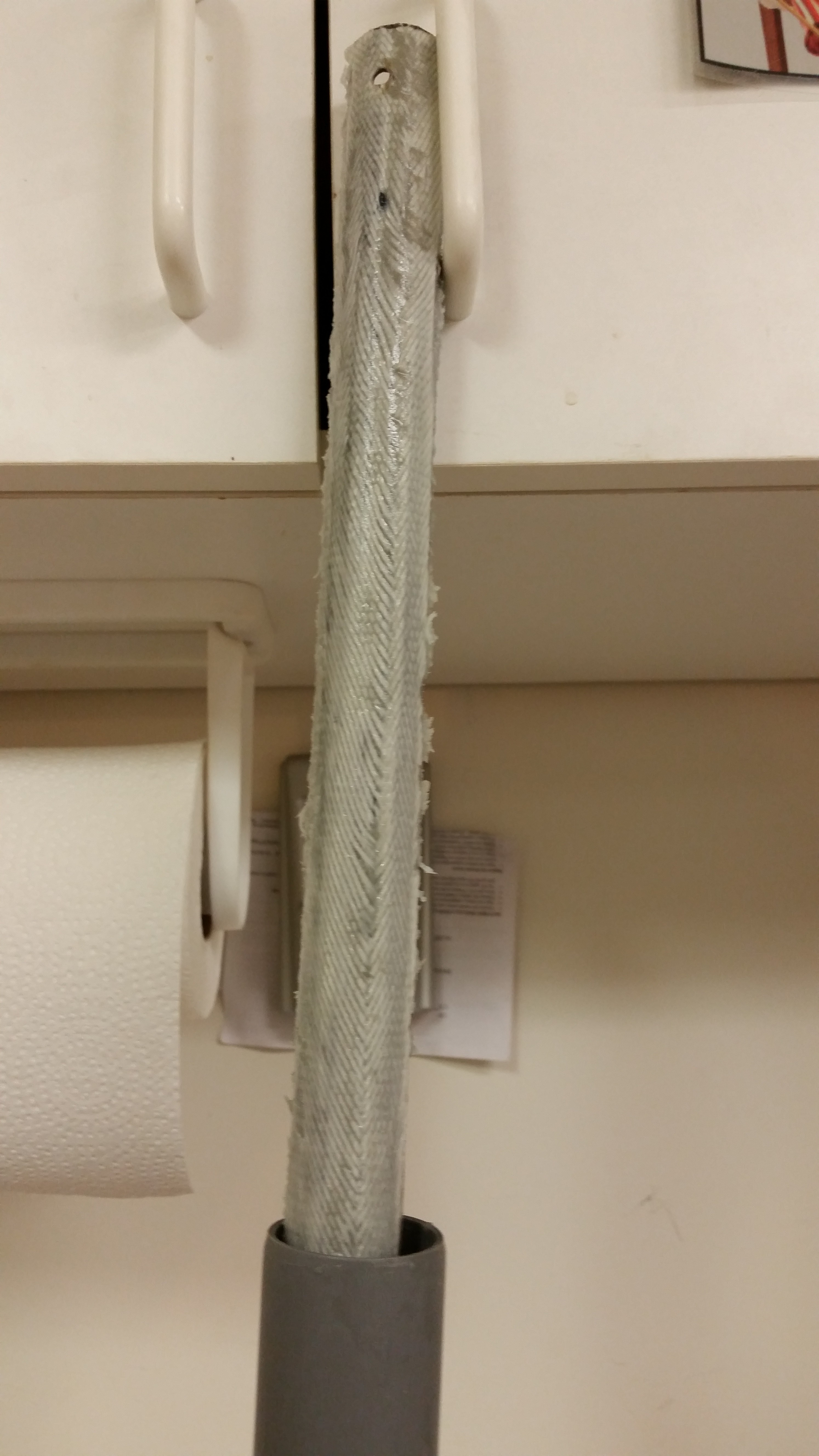
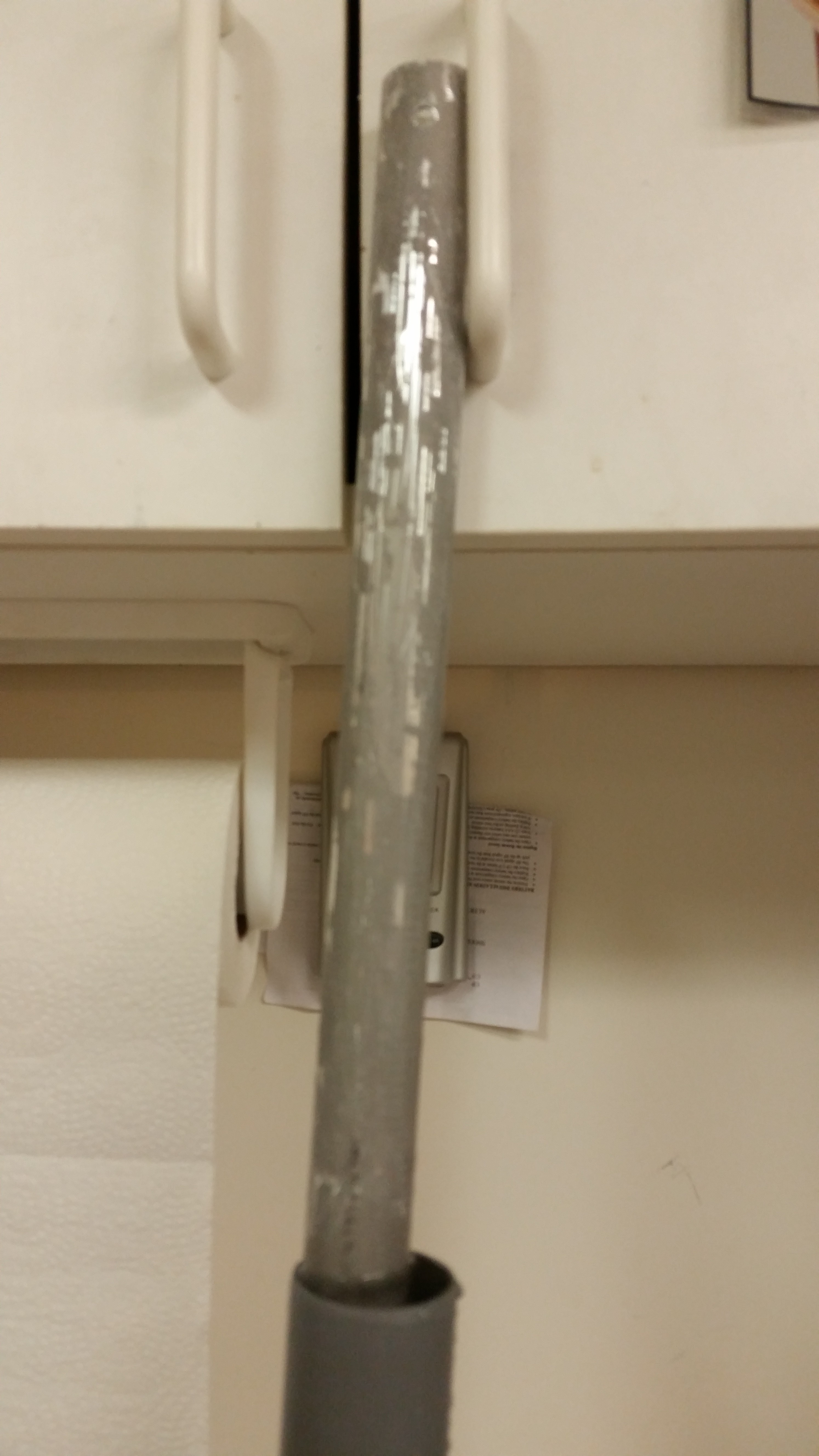
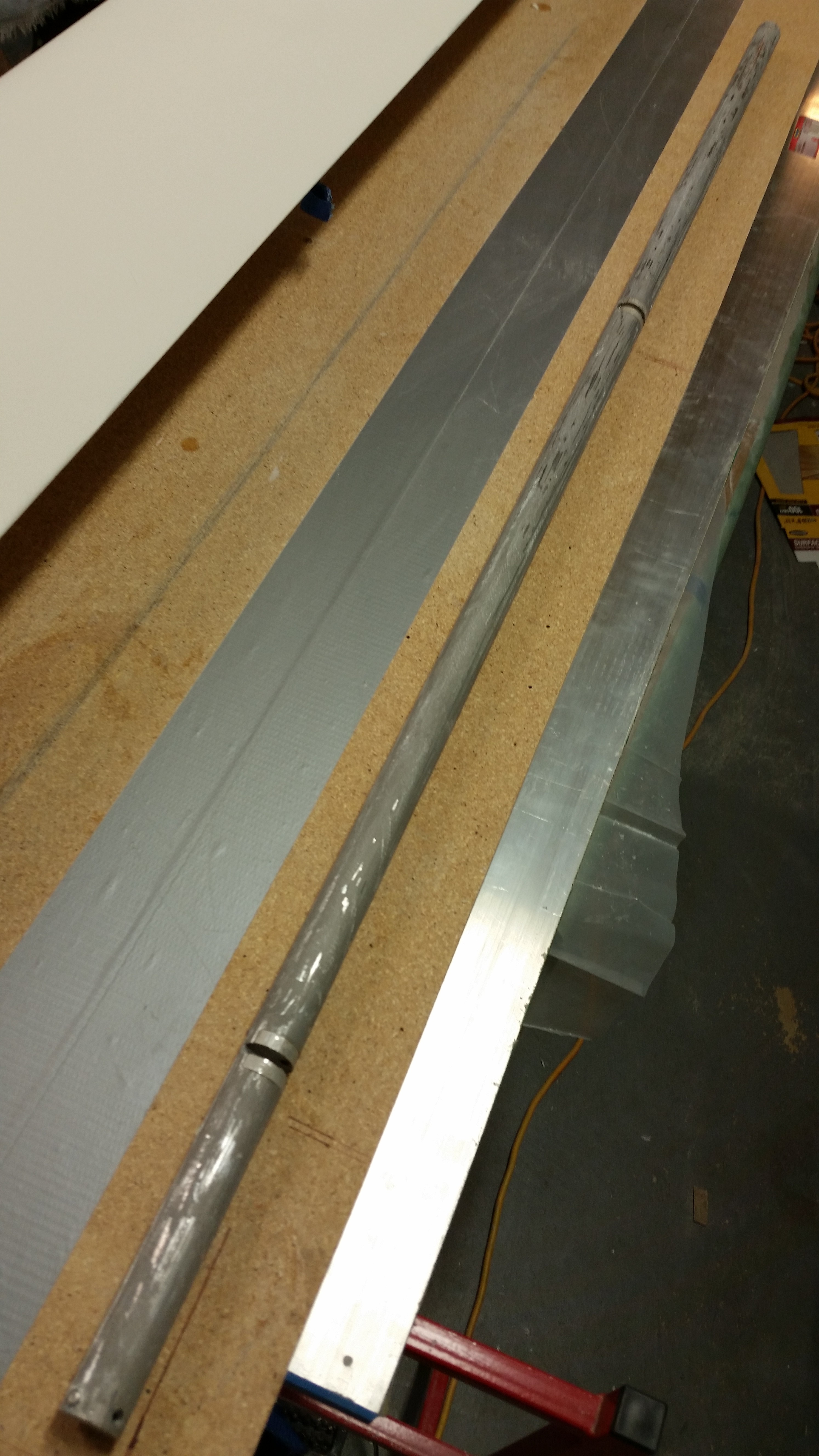
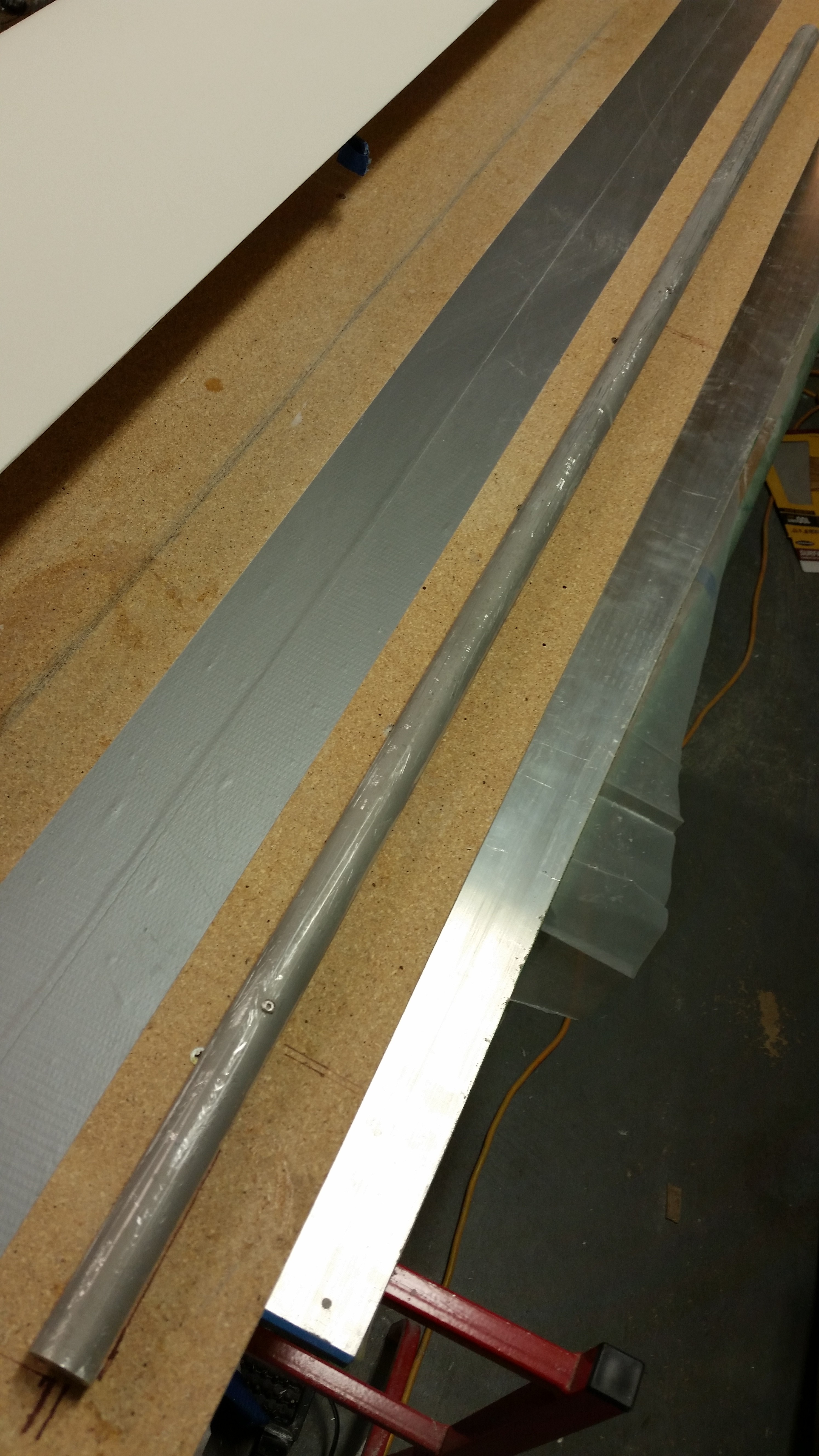
Here’s a couple shots of the elevator tube in its current state.  I would say it’s about 90% clean, and after I shot these pics I put it back in the PVC tube to soak in the vinegar over night.

Elevator tubeElevator tube

Finally, here are a couple of shots of the canard with nothing but a single light reflecting on its surface.  This provides a good view of the imperfections currently on the top surface of the canard.  As you can see, there are few minor imperfections –mainly simple & minor surface depressions– on each side of the canard top.

Canard surface view

Canard surface view

Tomorrow I plan on doing a final clean of the elevator tube, sanding down the surface, and then Alodining it in prep of micro’ing the elevator core to it.  I will also do a final sanding of the current primer on the canard top in prep of laying down a couple coats of the new primer.  I’ll then let the new primer cure 24-48 hours before giving it a final sanding.


Chapter 11 & 25 – Elevator DEconstruction

I started off spending a good hour, and 3 good long board sanding sheets, before I finally got the hint that although the primer looks cured, and feels cured to the touch, it’s not cured fully and that’s why my sanding sheets gummed up so quickly.  Argh!

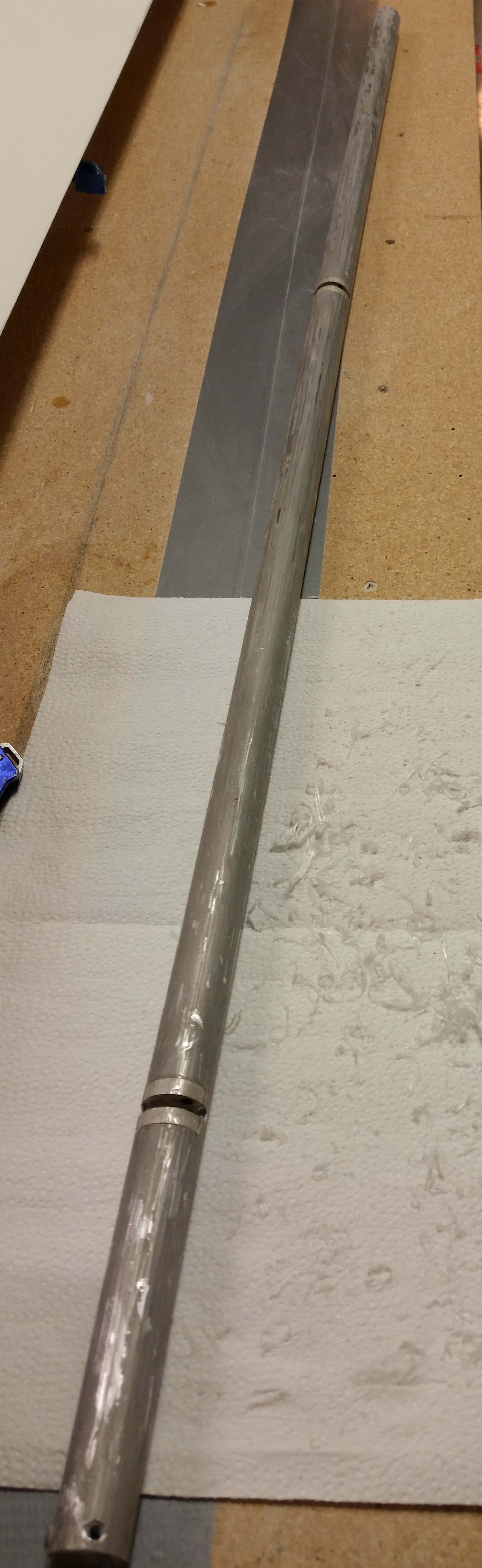
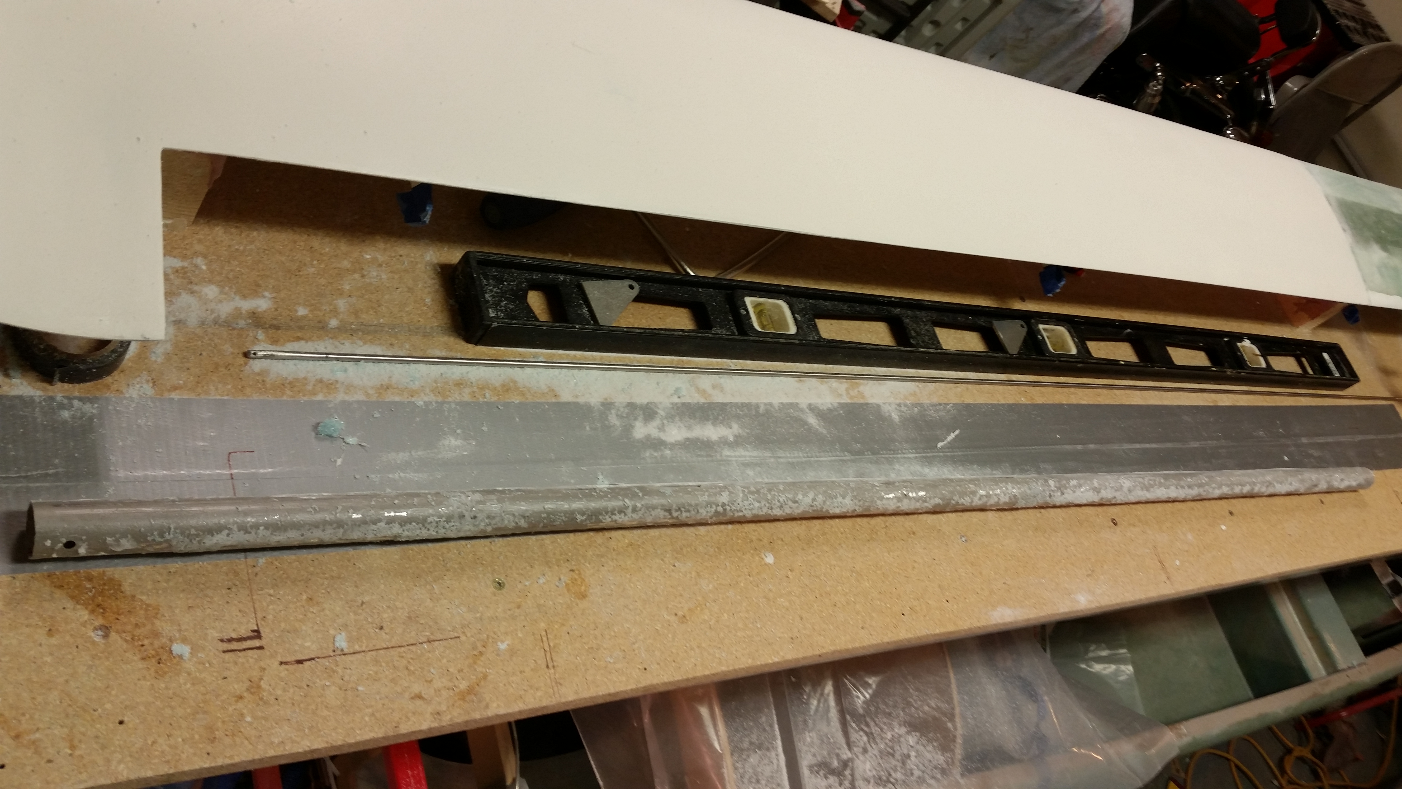
So I quickly stopped that futile endeavor and started working on the elevator build prep.  My first step was to ensure the table surface was level for the elevator build.  I pulled out the über awesome aluminum straight board that I picked up in Germany to check the work bench alignment.  From the corner to about 60″ in I had just about 30 thou of sag in the table.  A couple of quick shims and everything looked good, straight and level.

Checking table surface straightness

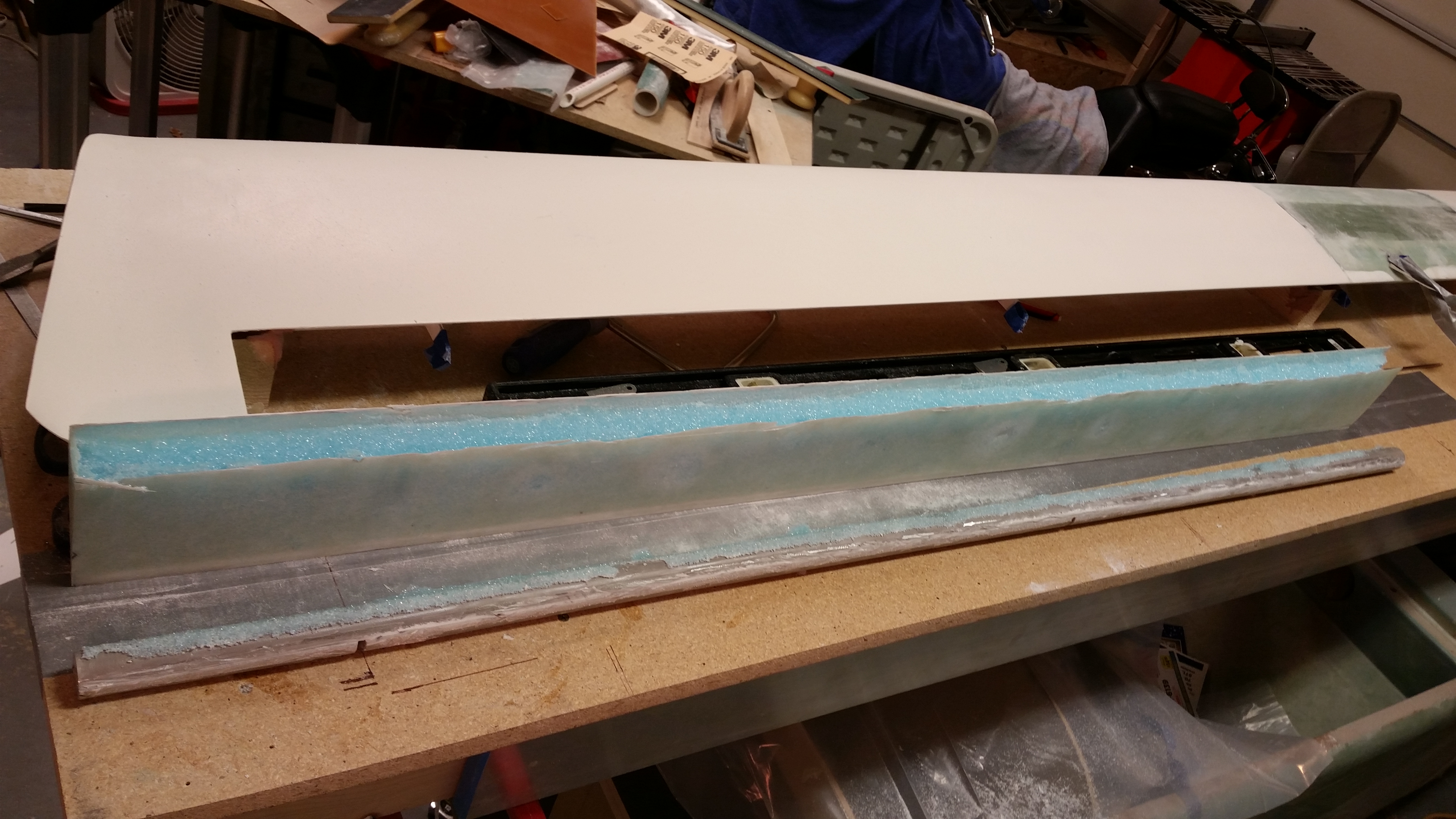
I laid down some duct tape where the TE of the elevator will run on the table and then got to work deconstructing the elevator.

Right elevator

The first task was to remove the torque tube offset from the inboard side.

Right elevator

And then the elevator weight on the outboard side.

Removing outboard weight

After cutting the UNI plies at the base of the foam on top & bottom, I gave the weight a sharp rap, snapping it off.  Unfortunately it came off a little less gracefully (read: intact) than I had hoped for, but I think with some judicious application of flox it may very well work on the next elevator.  BTW, as you can see below, the UNI pretty much peeled right off the weight with a little effort, but not a lot.

Outboard weight removed

I then broke out my old friends, the NC-7s, to get a gauge of how they line up currently in the hinge tab slots.

NC-7s . . . Again!

I diced up a popsicle stick to make spacers for the current NC-7 gaps to replicate this on the next elevator when the core is mounted to the tube.  And yes, I’m allowing for the .020″ that comes into play for the skin thickness.

Acquiring NC-7 spacing

I set the current elevator in a good position for the next one as it gets constructed, and then made some alignment marks in a number of places to help ensure the elevator core gets mounted to the tube in the same configuration as the current one.

Alignment marks

This pic may be a tad fuzzy, but here is the underside of the elevator with its significant thin areas due to intense sanding over the delams that are root cause of all the issues I’ve had with this elevator.  Not good.

Surface disfigurement

I broke out the Fein saw and started cutting right at the junction of the elevator core and the elevator tube at a very shallow angle.

Starting removal process

I would track this cut for a bit until the blade broke through the fiberglass, then was able to move forward another few inches before having to come back to the surface and start the process again.  Here is the actual cut through the skin.

Removing elevator from tube

And here’s the entire bottom side of the elevator skin cut just aft of the tube.

Removing elevator from tube

I then moved to the topside and did essentially the same thing.

Removing elevator from tube

I had to put a metal rod into the top of the elevator tube to pry it gently from the foam core, but it came off with a good amount of pressure.

Elevator removed from tube

Here’s the elevator tube after I went to town on it with the Fein saw to knock off all the leftover foam, epoxy & glass residue.  I then filled up a PVC tube with white Vinegar and dunked the elevator tube into it about 3/4’s of the way up the tube (not shown).  I’ll let that sit overnight and see if it softens up the goobers on the elevator tube.

Tube after initial cleanup

Tomorrow I’ll continue my quest in finishing this new elevator, and the final sanding of the primer on the canard.


Chapter 13 & 25 – Rock the Casbah!

Or rather the canard!

I started out today by sanding the pure epoxy coat on the topside of the canard.  I began with 120 grit on the long board in a 45° pattern, both to the left and to the right.  After I sanded both sides with the long board, I then switched to 220 grit and wet sanded the epoxy finish.  This helped get the lower lying areas that should get filled with the high build primer.

Sanded down canard top

Here’s a shot of the right side.  For some reason the blog didn’t like the left side pic since I couldn’t load it.  Needless to say, it looked about the same.

Sanded down canard top

I then applied primer to the canard.  The shot below to the left is the first coat, and the right is the second coat.

First coat of primer

Second coat primer

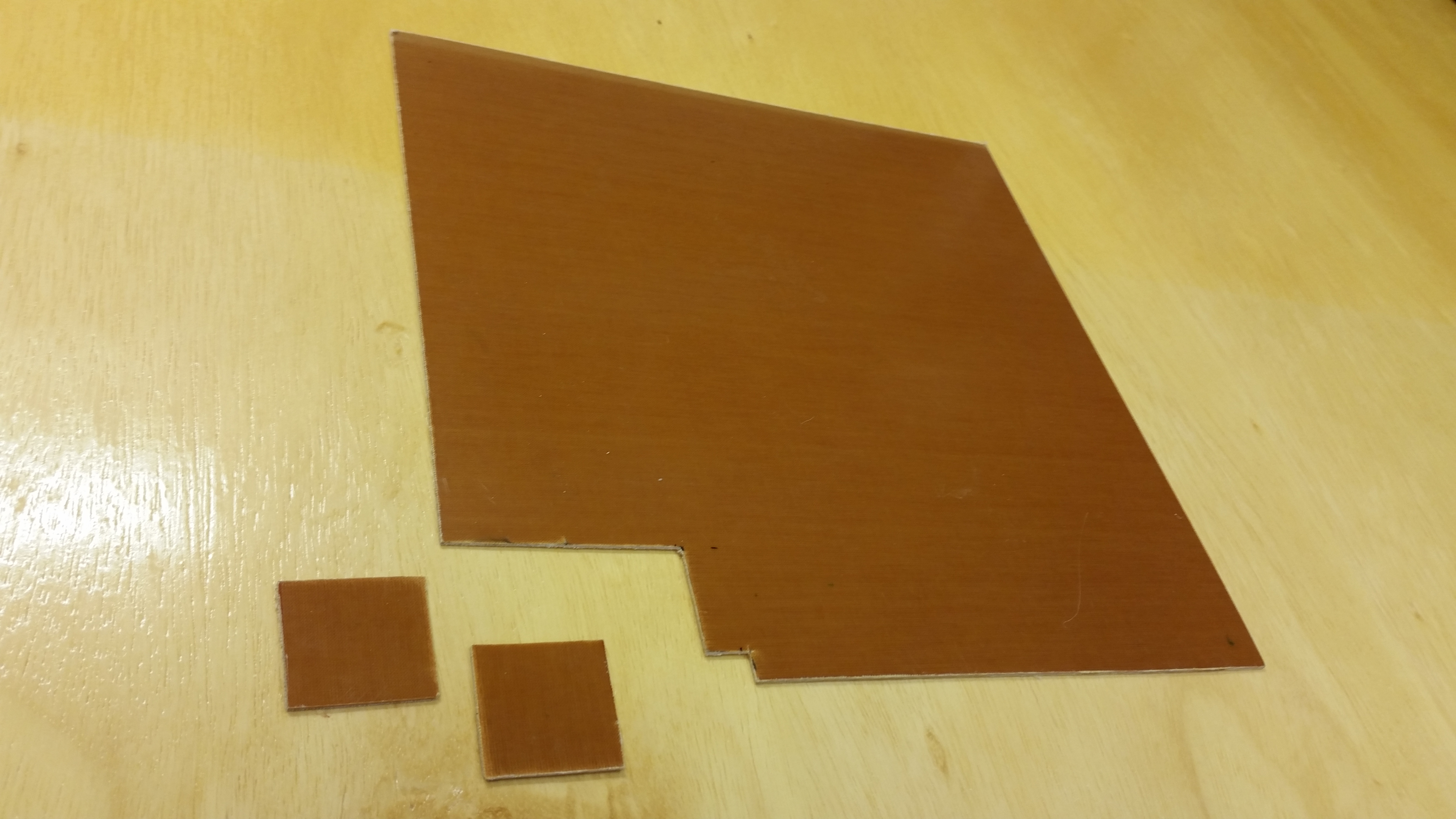
In between priming the top of the canard, and watching football, I cut out the 2 phenolic support pieces that will be embedded in the NG30 cover for the AMP CPC connectors.

1/16" phenolic for gear actuator connectors

I also cut the 8 pieces of UNI for the new elevators that I will be rebuilding here in the next week.

UNI cut for new elevators build

In total I added 3 coats of primer.  I’ll wait until its cured tomorrow to block sand it.

Also, as I was prepping the canard for primer I happen to really note the color of the boat paint on the headrest GPS antenna cover and the ice shields.  It’s not a bright white, as the primer is not, so I’ll be calling Jamestown Distributors this week to figure out the way ahead on that.  I want the white on my bird to be as white as possible… not the 1970’s dull off-white stuff.  So I’ll be evaluating the paint further as I move forward.


Chapter 25 – The canard riseth!

I finished the 4th application of pure epoxy around 2am, and after that I was tapped out.  I realize now I need to program in 2-1/2 to 3 hours between epoxy wipes on the surface being finished since 2 hours just isn’t enough.  Especially considering that each application of epoxy takes about a full half hour from start to finish to complete.

So, my total epoxy applications at this point is four (4) vs the planned five (5).  This actually works out fine because I can tell that I have some areas, the biggest being about 2″ wide, that will need a little bit more fill.  In addition, the simple action of repeated sanding –once the primary shape has been locked in with the epoxy finish– refines the surface finish when it finally comes to paint.  This may seem like an overly simplistic & obvious statement, but it is true and very evident during the sanding process.

Four layers of pure epoxy

Four layers of pure epoxy

Thus, my “new” (slightly modified) plan was to sand down the current epoxy wipe quite a bit to knock down the high points, level out the surface between the high & low spots, and bring the entire surface of the canard to a much tighter equilibrium finish elevation wise.  Then I would add another 2-3 coats of pure epoxy.

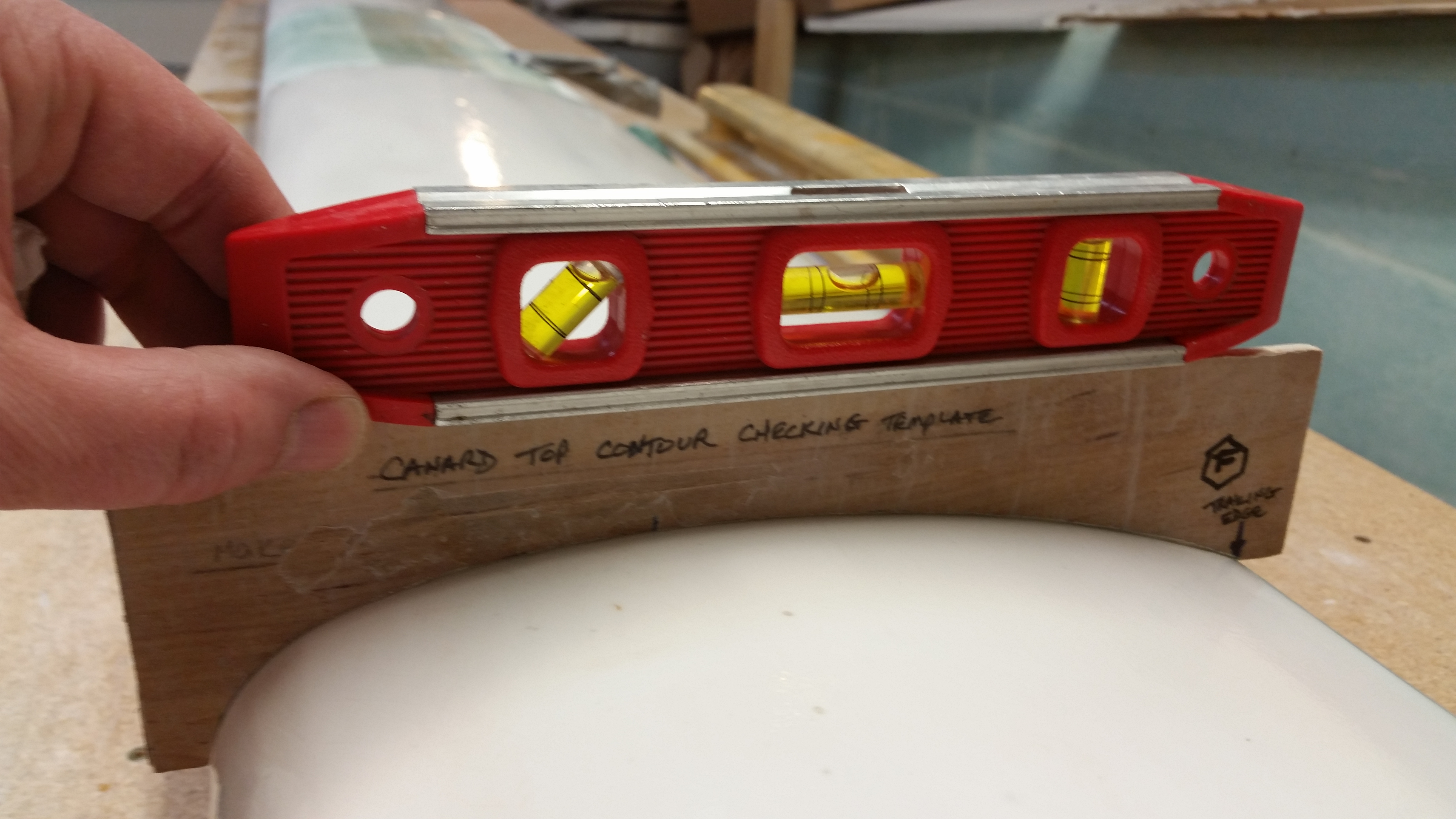
I started by checking the surface contour of the canard by not only focusing on the actual contour as compared to the bottom edge of the “F” template, but also by concentrating on the incidence angle that is being conveyed via seeing how the angle of the top straight edge of the “F” template matches the angle of the work bench.  In the picture below I have a really good top canard surface contour in addition to a spot-on incidence angle.

Profile looking good!

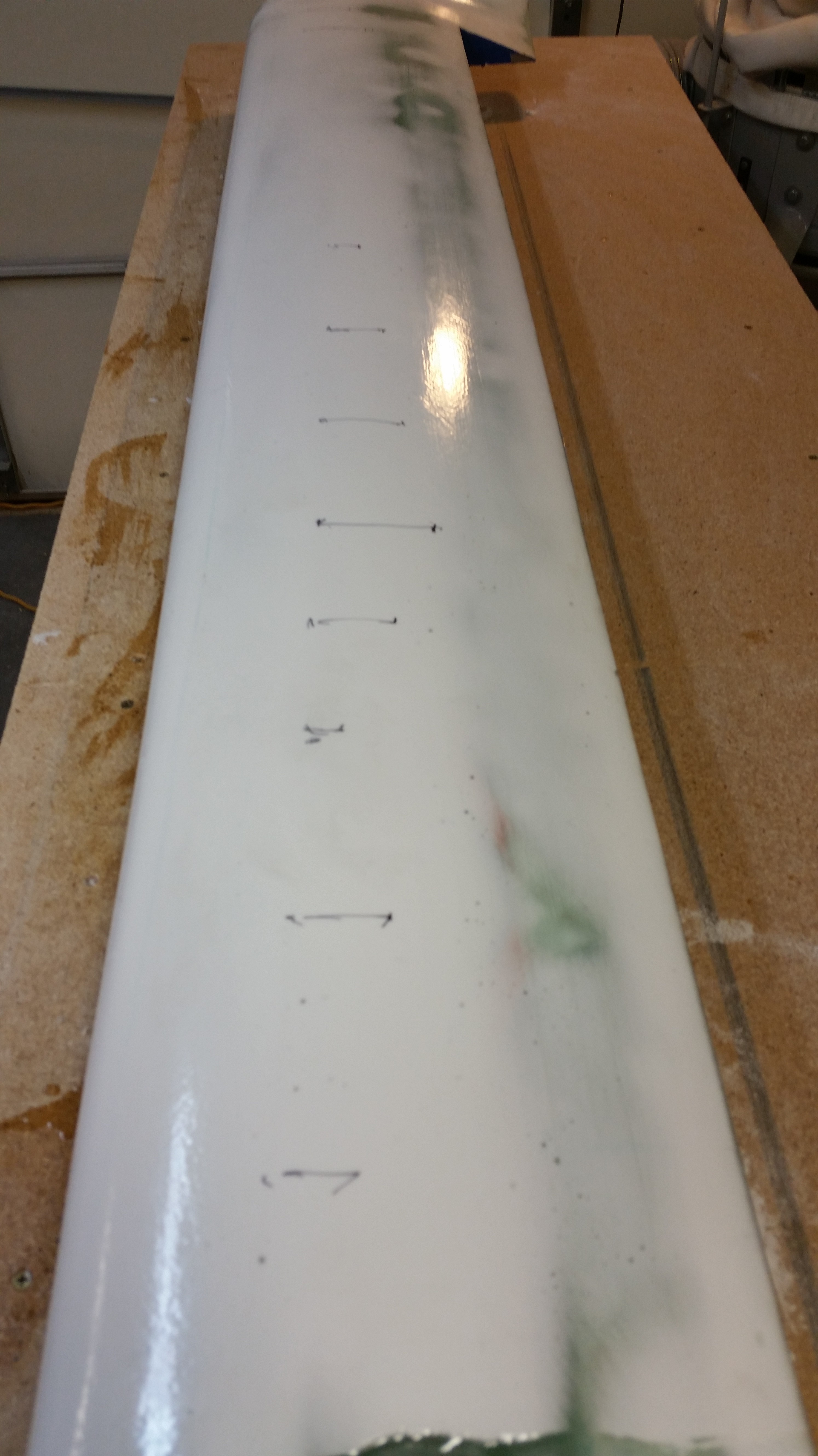
I then completed the contour check about every 4-6″ along the top surface of the canard. Below you can see the contour sanding lines I drew on the right-side canard top that denote the high points that need to be knocked down a bit for the canard surface to be better aligned with the contour checking template “F”.

To be clear, by cleaning up the contour profile of the canard (bottom side of “F” template) it had a direct effect of bringing the incidence angle into better alignment (top of “F” template).  As it stood, the areas where I marked the lines acted as a high point, or fulcrum if you will, where the contour template teetered upon one way or the other.  That being said, it was actually rather apparent that by reducing the middle high point, or “ridge,” that the forward part of the “F” template fell towards the LE and thus brought the incidence angle into proper specs.

Contour sanding marks

Here’s a shot of the canard after about an hour’s worth of sanding with the long board with 80 grit first, then 120 grit.

Sanded canard

I then applied 3 more coats of pure epoxy, waiting 2-3 hours between each coat.

3 final coats of epoxy

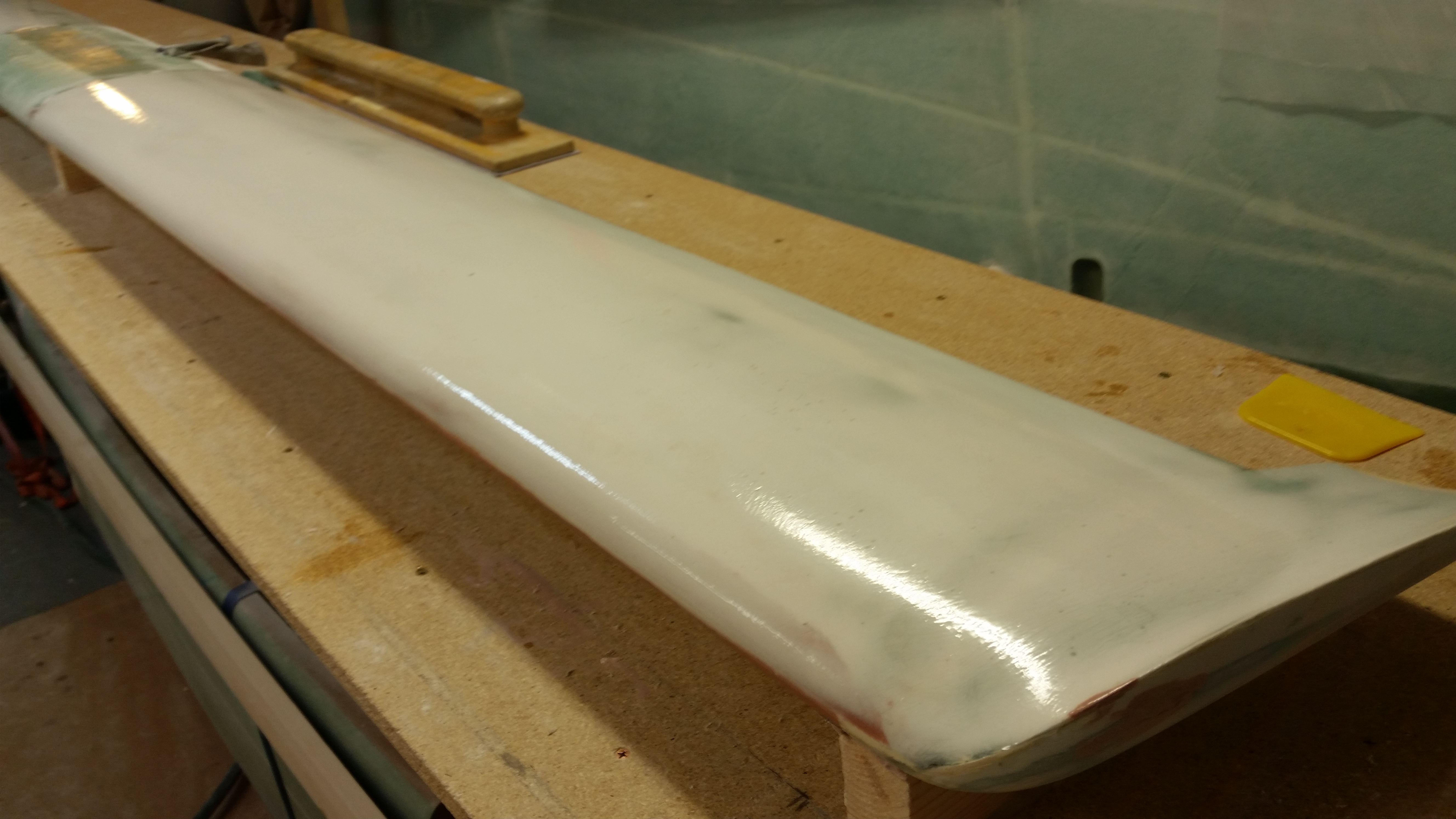
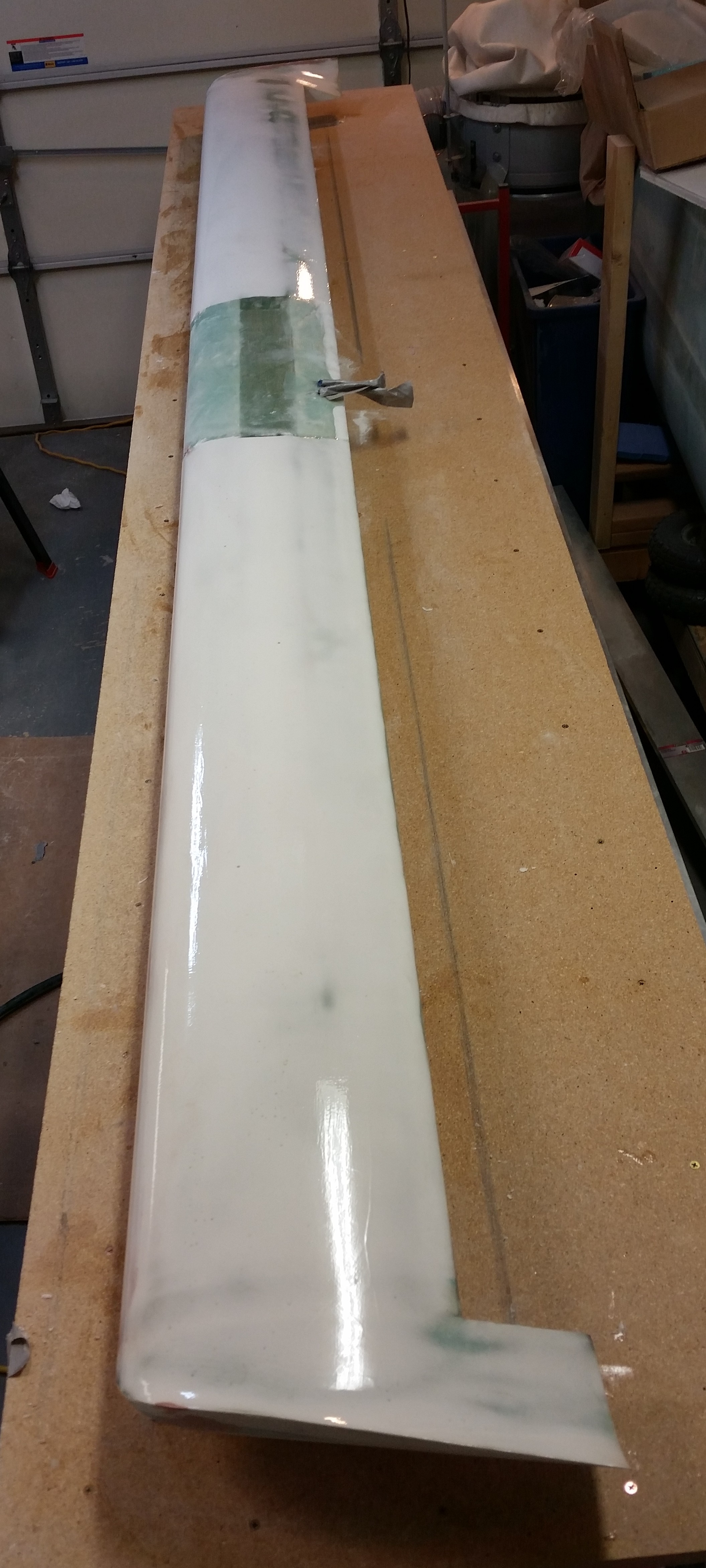
Here’s a shot of each side of the canard with the final 3 (additional) coats of epoxy.  A few hours after the final coat went on, I spent about 45 minutes pulling the remaining protective tape from the sides and cleaning up the TE, LE, and swoosh tip areas with a razor blade.  I got most of the gunk off these areas, but some still remains that will have to be sanded clean once I flip the canard for the final contour of the bottom side, with special focus on the LE.

3 final coats of epoxy3 final coats of epoxy

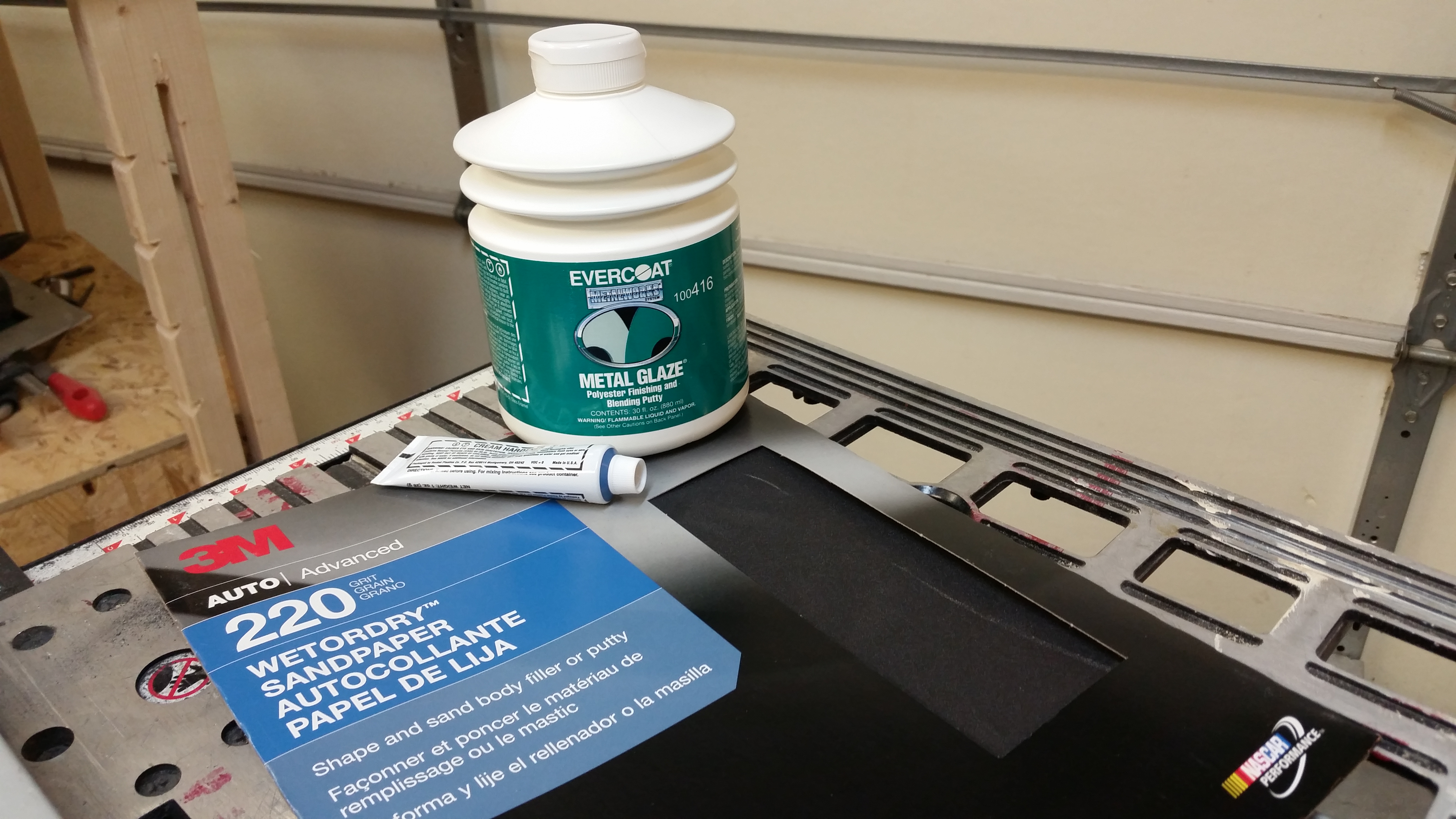
During one of the ~2 hour curing times between coats I ran out to a auto paint supply store to grab some glazing putty & wet/dry sandpaper to have on hand for this weekend.

Some finishing accessories

I’ll wait a minimum of 24 hours for the epoxy to cure before I do anything to the canard top.

Chapter 25 – Cory Bird is a Genius!

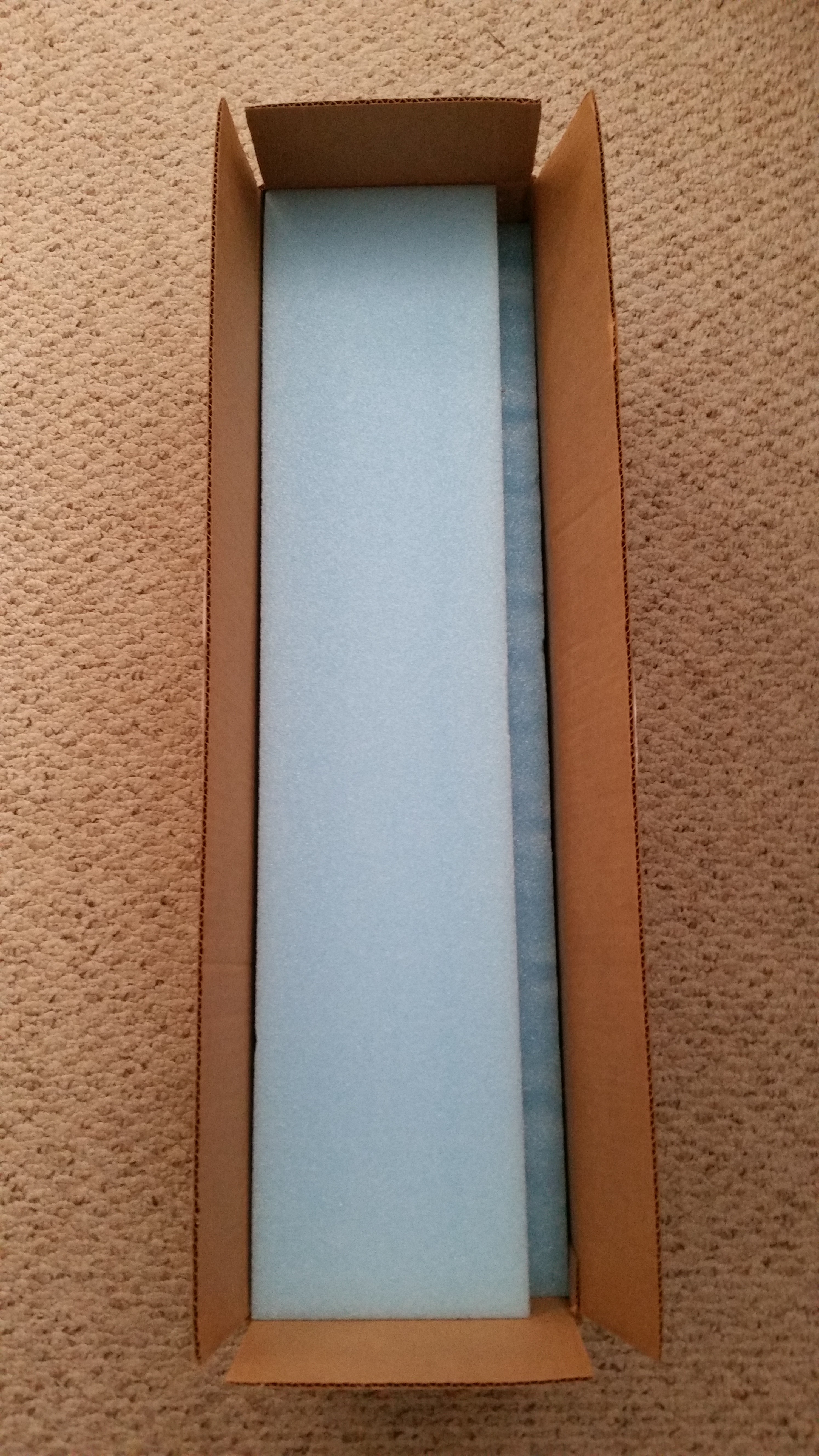
First off, before we get to Cory, as you can see by the pic below my new elevator cores arrived from Eureka CNC!  Thanks Steve!

Eureka CNC Elevator cores

After doing about an hour’s worth of research on some electrical topics for wiring the nose gear actuator, etc. I picked up my long board to sand yet once again.  (whew! … I’m not gonna get back on my soap box, but I still can’t imagine doing nothing but finishing for MONTHS on end!).

After about 15 minutes of sanding I was very close to the my final contour on the left hand side.  On the outboard third of the canard I’m maybe about 30 thou of inch (0.030″) too wide from LE to TE, but the profile is great.  And since I was closing in on the LE Bondo layer, and the inboard two-thirds looked really good, I called the left side around 97% good.  Any more sanding would have only gummed things up in my opinion, so I stopped while I was ahead.

Contour looking good!

The right side canard top surface didn’t come out as awesome as the left, but it still looked really good.  Since I had to do quite a bit of sanding on the LE area, I tapered it closer back to the shape where I was compelled to add another micro layer.

When I checked the right side with the contour profile template I got 3 near-perfect contours, 2 good contours, and one just ok.  Now, again, instead of sanding further and just compounding the problem, I decided to let the 5 coats of epoxy and 2-3 coats of primer take care of any minor surface deviations, and will backfill any major abhorrent surface irregularities that exist in the final finish steps.  Taking off a gross amount more of micro finish wouldn’t have done anything but make the overall contour profile even worse.

If I had to call it in percentages of optimum contour, I would give the right side a grade of anywhere between 85% and 89%, at it’s current state.  That being said, I’m confident that it will be at a grade of 95-98% of optimum contour by the time I’m finished.  Moreover, I’m really happy with how the top canard profile turned out!

Ready for epoxy!

I shop vacuumed the work bench and the top of the canard, and then taped up the bottom edges to control any overflow of out-of-control epoxy.

Ready for epoxy!

I then mixed up some pure West epoxy and spread it over the canard surface top starting on the right side.  It’s amazing how the epoxy wipes removes so many of the sins of micro finishing.  I’m not, of course, endorsing sloppy workmanship, but it’s nice to know that the divots, holes from air bubbles and depressions from not enough thickness in the application of micro will be greatly minimized, if not eliminated altogether, from 5 good applications of a very thin layer of epoxy.

Thus, again, Cory Bird is a genius!  And I’m glad he made this maddening process a heck of a lot easier . . .

Epoxy wipe #1

I then finished up on the left side.

Epoxy wipe #1

After the second application of epoxy to the canard top, I sanded down the first coat of final top coat paint on the headrest GPS antenna puck cover, and then sanded down and added the first coat of final white paint to the elevator outboard weight ice shields.

Now, to be honest I haven’t been blown away with the performance of this boat paint.  I don’t have negative feelings towards it either, but the jury is still out.  I may need to look at a better way of applying it, because on these parts I just used a cheap paint brush.  Thus, we shall see . . .

Painting a boat!

My plan for the rest of the evening is to get the final 3 coats of epoxy applied to the top surface of the canard.  In lieu of this, I won’t be adding any more to this post this evening.

Tomorrow, I’ll be prepping for the building of the elevators while the epoxy cures. Tomorrow evening I’ll most likely do a final sand of the epoxy covered canard and hit it with its first coat of primer.  And I still need to add some material to the right swoosh tip edge as well.


Chapter 25 – Inching forward…

To start, I cheese grated both LEs & the various spot fills on the canard surface shortly around midnight.  I have to say that I notice when sanding micro it seems to be tougher at the beginning when breaking through the shiny layer of epoxy that cures on the surface of the micro.  Once into & through that layer, the sanding tends to go a little faster with ever so slightly less pressure (ahem, not implying that a good bit of umph isn’t still required!).  Well, cheese grating seems to get to the point where that top shiny surface layer has already been broken through.  I’m hoping this is the case and that any difficulties that arise between sanding between micro layer #1 and added micro layer #2 is minimized by cheese grating.

An important realization that I had when I cheese grated the right LE is that the LE still wasn’t thick enough for my (and the contour profile template’s) liking.  It was late though & I really didn’t want to be up for another 30-45 minutes, so I left the adding of micro finish layer #3 until this morning.

After I got done cheese grating the top canard surfaces, I pried apart the two halves of the headrest by slowly & carefully inserting straight razor blades around the entire sides & back side of the edges where I applied the micro.  A big oops here and thank goodness I caught it in the green stage, because this would have been near impossible if the micro had fully cured.  I thought that the peel ply would make it so the two sides came apart with the typical & gratifying peel ply tear off, but this was a solid cure and turned the top & bottom “halves” of my headrest back into one solid piece.  Yes, if it ain’t one thing it’s another!  Ha!

That’s 30 minutes of my life I’m not getting back!
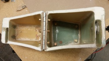
Headrest - edges micro'd

This morning I added more micro to the right side LE.  Again, we’re talking if I get 1/16″ added filler depth after sanding (which is always the trick! that damned sanding inexplicably tends to remove the stuff you put on in the first place… bewildering!) then I’ll be happy.
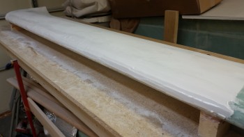
Right side LE re-micro'd

I also noted after checking the canard surface with my contour profile template that the aft side of the left side canard has just a bit of daylight, so I skim coated with micro the entire left side aft canard about an inch forward of the LE in about a 3″ swath.  Here, anything that provides a little extra surface depth is golden since I’m not overly concerned about this area.  But since I’m contending with other areas on the top of the canard, I might as well take the opportunity to tweak this area as well.
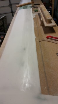
Left side TE strip re-micro'd

Yesterday, when I wrote up my 3×5 card to-do list (or “cut sheet”) for finishing the top of the canard, I added tasks that I can do in-between the epoxy wipes during the 2-2.5 hours it takes for the epoxy to set up for the next coat of pure epoxy.  These are those small, gotta do tasks that SHOULD get done eventually, but don’t hold a lot of weight in actually getting the plane built, or at a minimum, have anything to do with the current chapter at hand.  Of course there’s been a myriad of these pesky tasks that require completion: from adding the click bonds to the wing root rib, to micro’ing the edges of the headrest, cutting the 4130 engine mount extrusions, etc.

Although clearly I have not yet started the epoxy wipes on the canard, since I have to wait for the freshly added micro layer #3 to green, I started in on my list of these tasks… the first one being to sand down the base of the rollover on each side to clean up the irregular surfaces & shoot it with primer again.

Sanding round #1 I used 100 grit paper on each side, then did a final round #2 sanding with 220 grit paper.
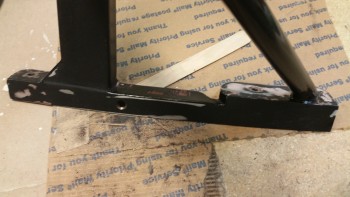
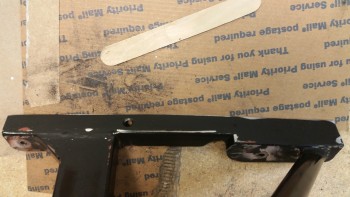
sanding rollover base

sanding rollover base

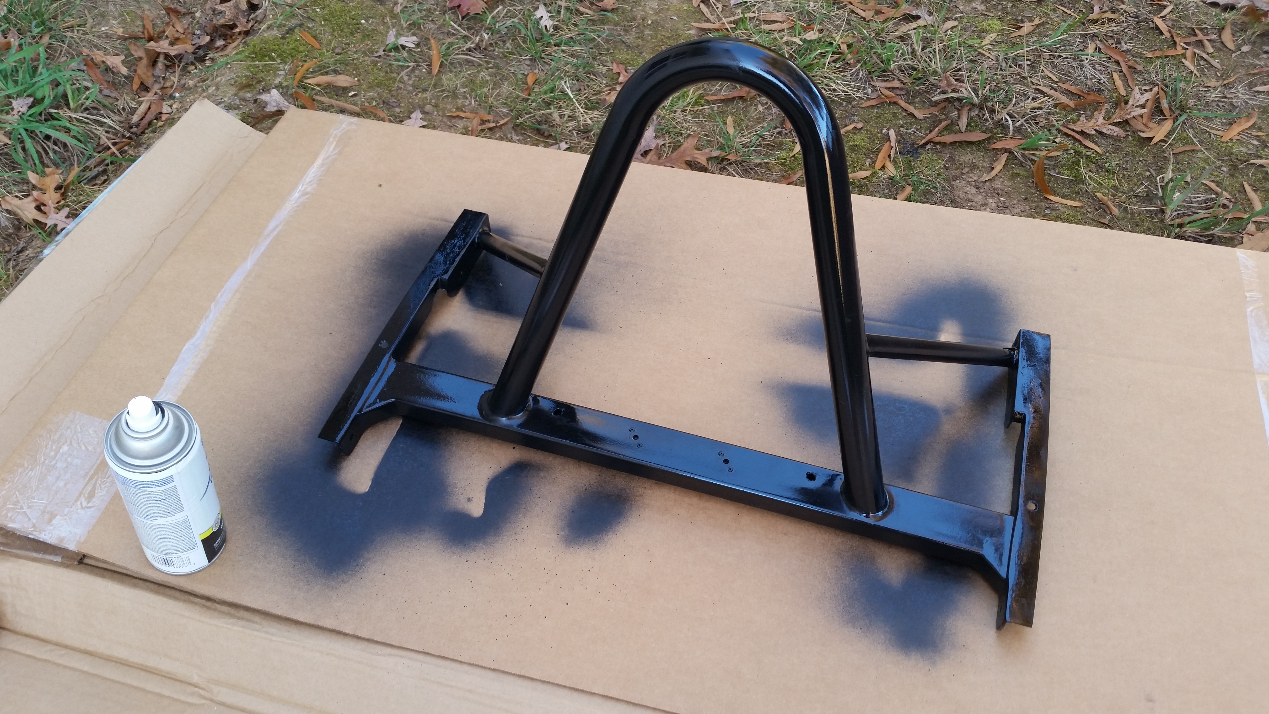
I then cleaned up the freshly sanded surfaces with Simple Green, took the rollover assembly outside and shot the sanded areas with 3 coats of the same Rustoleum gloss black primer that I used previously.
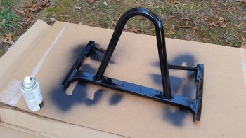
3 coats of gloss black primer

With my canard micro still not “greened” yet, I spent a good 45 minutes cleaning up and organizing my garage work shop (much needed, and yes, on the to-do list!).

After my cleaning spree, and with both the rollover assembly and the re-micro’d canard still curing, I decided to test out my boat paint on the headrest GPS antenna puck cover.
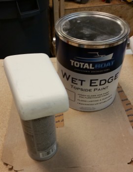
Painting GPS antenna cover

I duct taped the antenna cover to the top of a paint spray can and then brushed & tipped on the first coat of white boat paint.  This will be the first of a few test applications I use to see if I’m going to move forward with using boat paint, or at least this brand of boat paint.
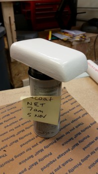
Painted GPS antenna cover

Finally, the new micro was at a good green stage to cheese grate it.  I spent a good 20 minutes cheese grating the LE edge area and then I quickly hit the left-side TE swath that I had applied at the same time as the right-side LE.

If you look closely in the pic below, you can see that the swoosh tip has some Bondo on its ridged edge.  I applied this shortly after micro layer #3, but forgot to snap a pic of it, which I rectified below.
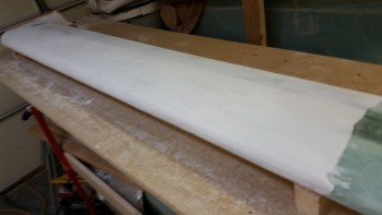
Right side LE cheese grated

Here’s a shot of the bondo on the swoosh tip ridge edge.  It needs to be built up just a hair to A) cut a near straight line profile-wise from front to back since it has a very slight dip, and B) the ridge needs to be just a tad bit more pronounced (read: higher) to better match the left side ridge.
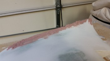
Right swoosh tip edge build up

Again, I know Bondo is MUCH heavier than micro, so I’m using it very sparingly, but I know from experience that it’s some tough stuff.  As you can see below, just from the very initial sanding, that I’ve knocked off about 80% of the Bondo that you see above.  Once I get the ridge set, I’ll probable follow up the Bondo with a final application of flocro (micro & flox mixed together) to smooth out any irregularities and add to the strength of the ridge.
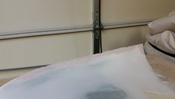
Right swoosh tip edge build up

As I was just finishing up with the cheese grating I heard the distinct sound of my neighbor’s Harley.  I haven’t seen my neighbor Dave around in weeks, and with my bike sitting in the driveway at the ready, I ended up going on a scoot for a few hours with Dave.
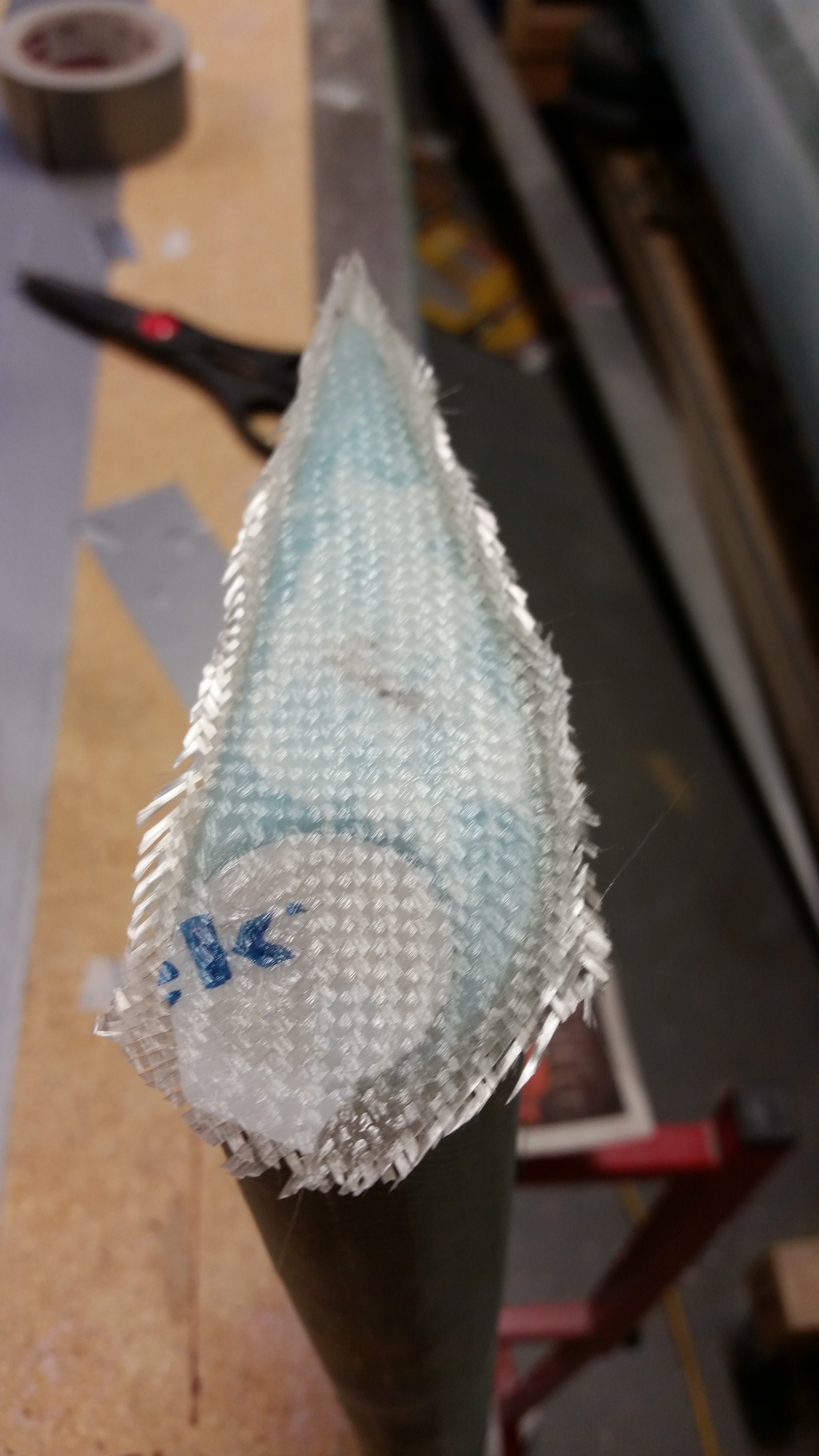
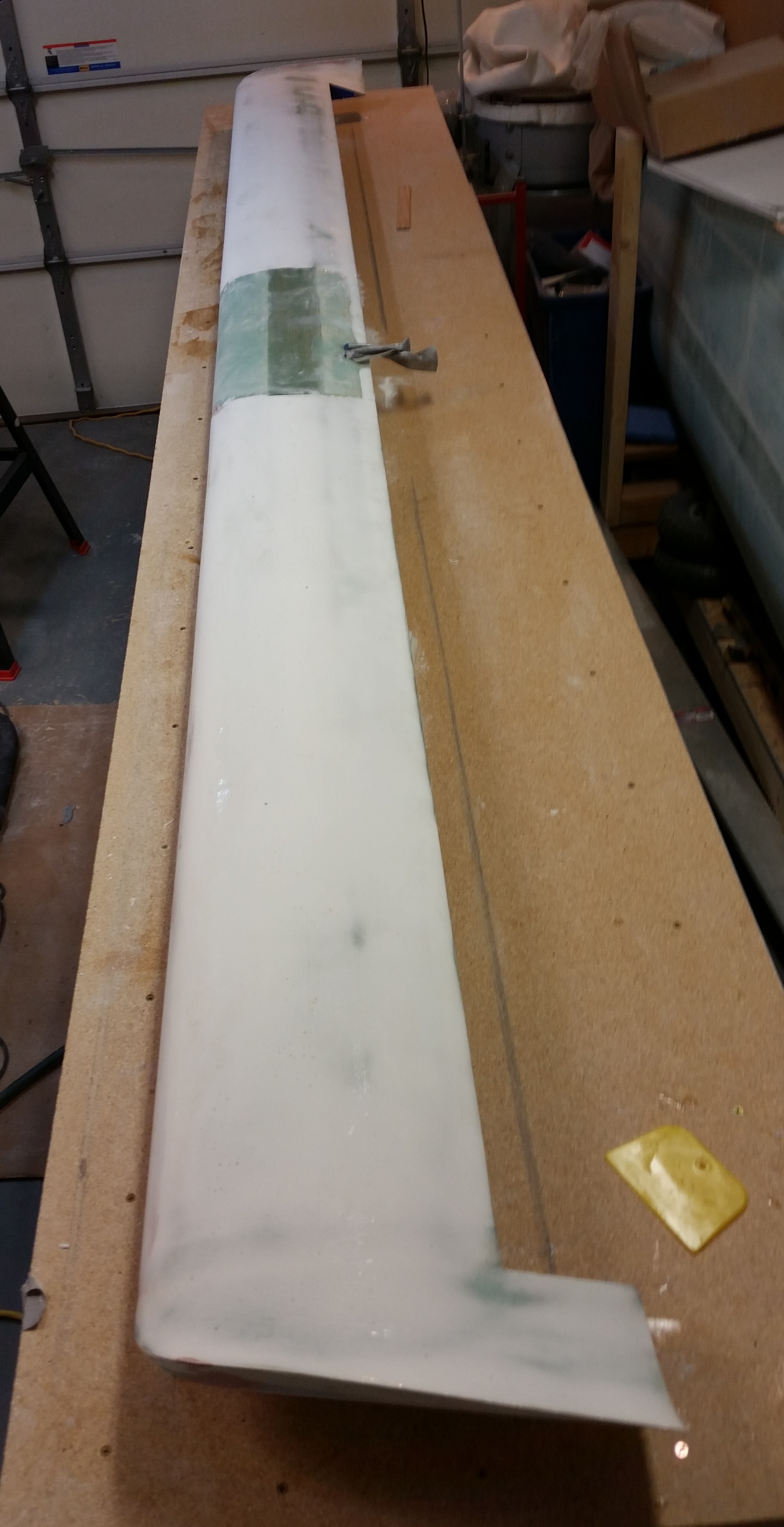
Tomorrow I plan on actually getting the top of the canard finished to its final contour & shape, and then get the 5 coats of epoxy squeegeed on.  Also, as an update, the original FedEx ETA of today for my Eureka CNC elevator cores has been slipped to the right one day until tomorrow.  No worries since I obviously need to get this canard finishing complete to clear up workbench space to build the elevators.