Chapter 25 – Sometimes you’re the hammer…

. . . yep, and sometimes you’re the nail.  Today, I was the nail.

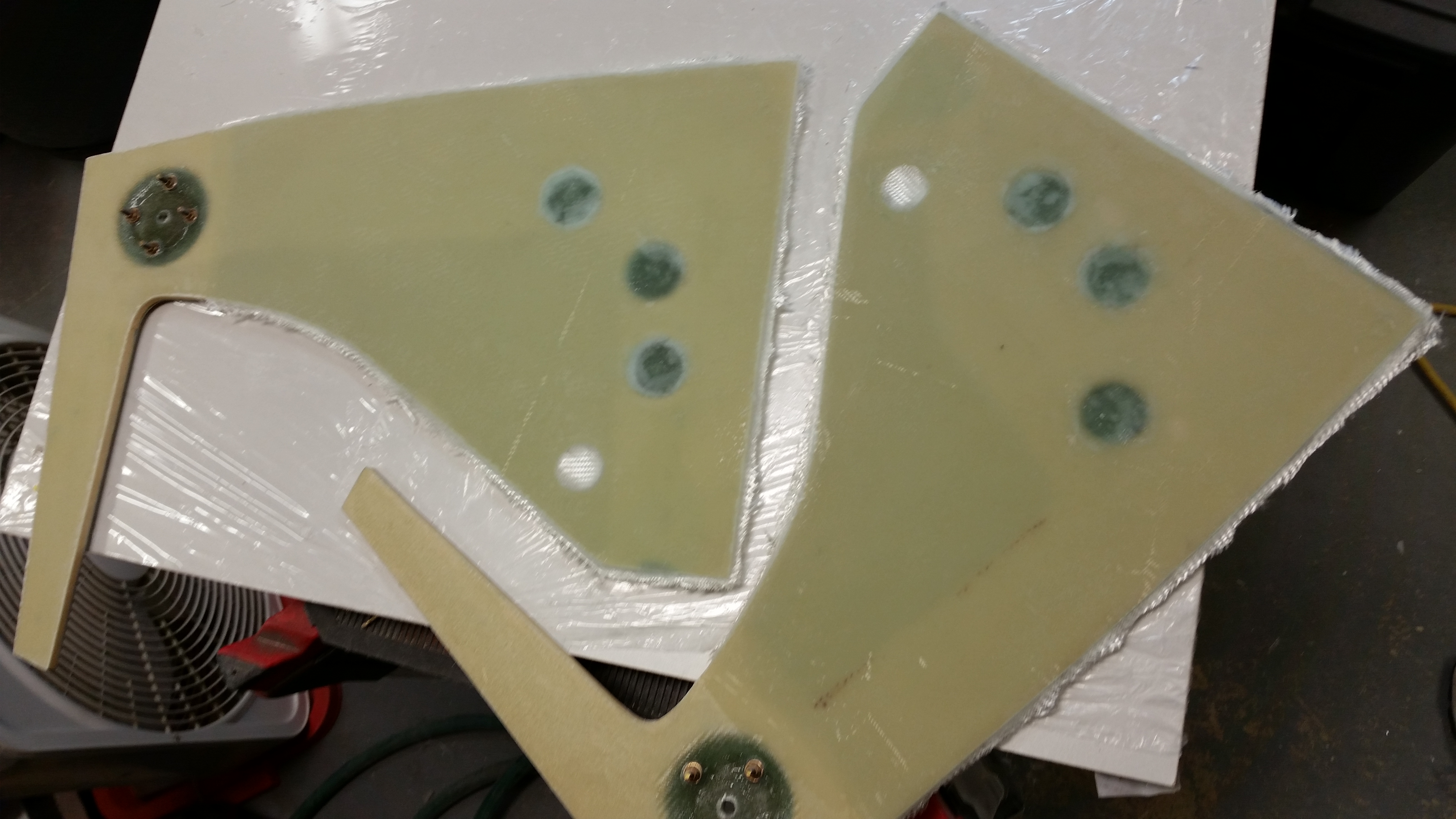
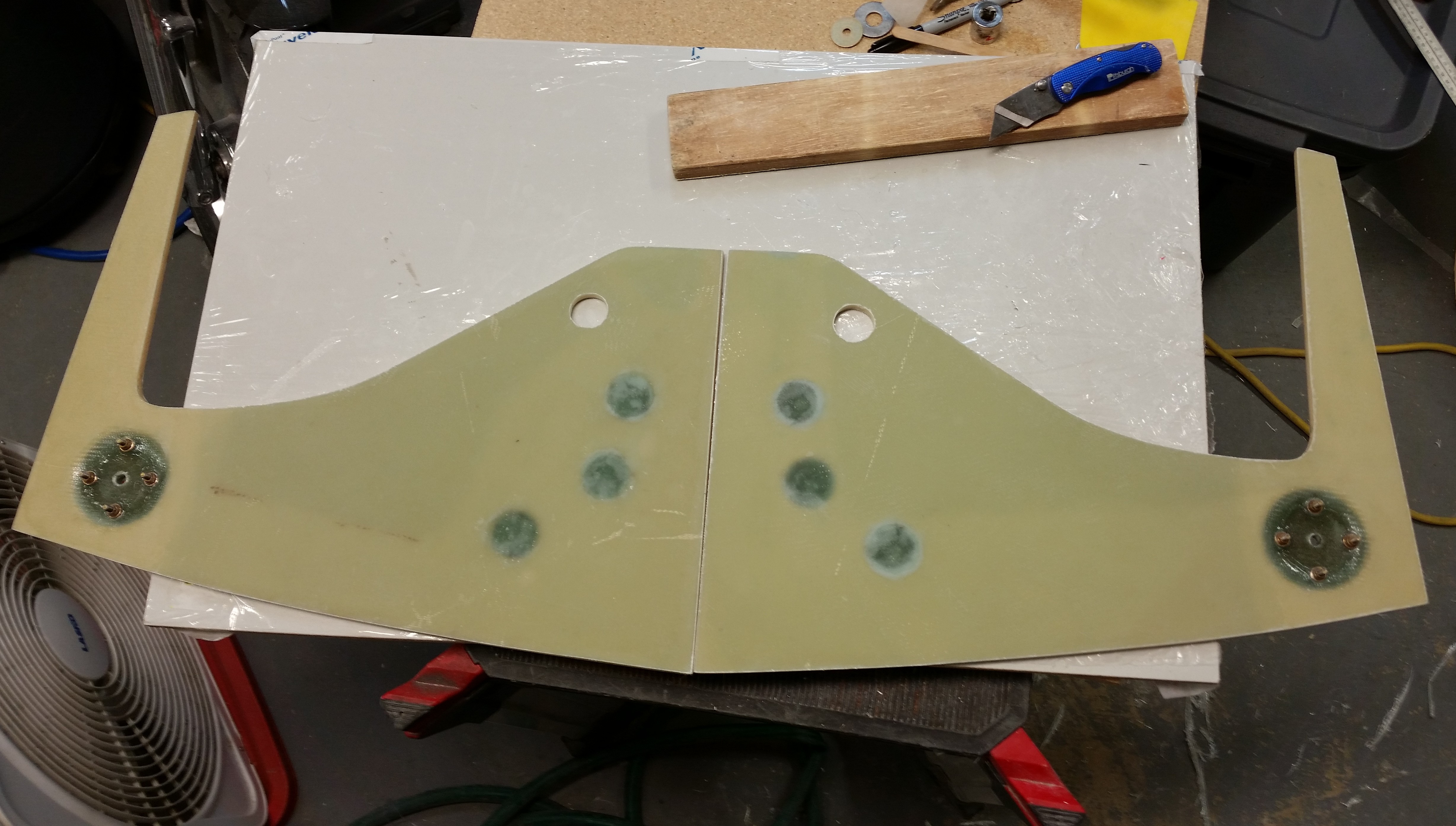
Since the weather was good, I decided to wash off all the sanding dust off my motorcycle and then cut the 4130 steel engine mount extrusions.  Now, as far as I know you can’t buy 1″ 4130 angle “iron,” so I bought 1″ x 1″ x 1/8″ square tubing a couple of years ago for the engine mount extrusions.  I figured I would merely cut the tubing along opposite corners and Voila, I would have my L-shape angled 4130 pieces.

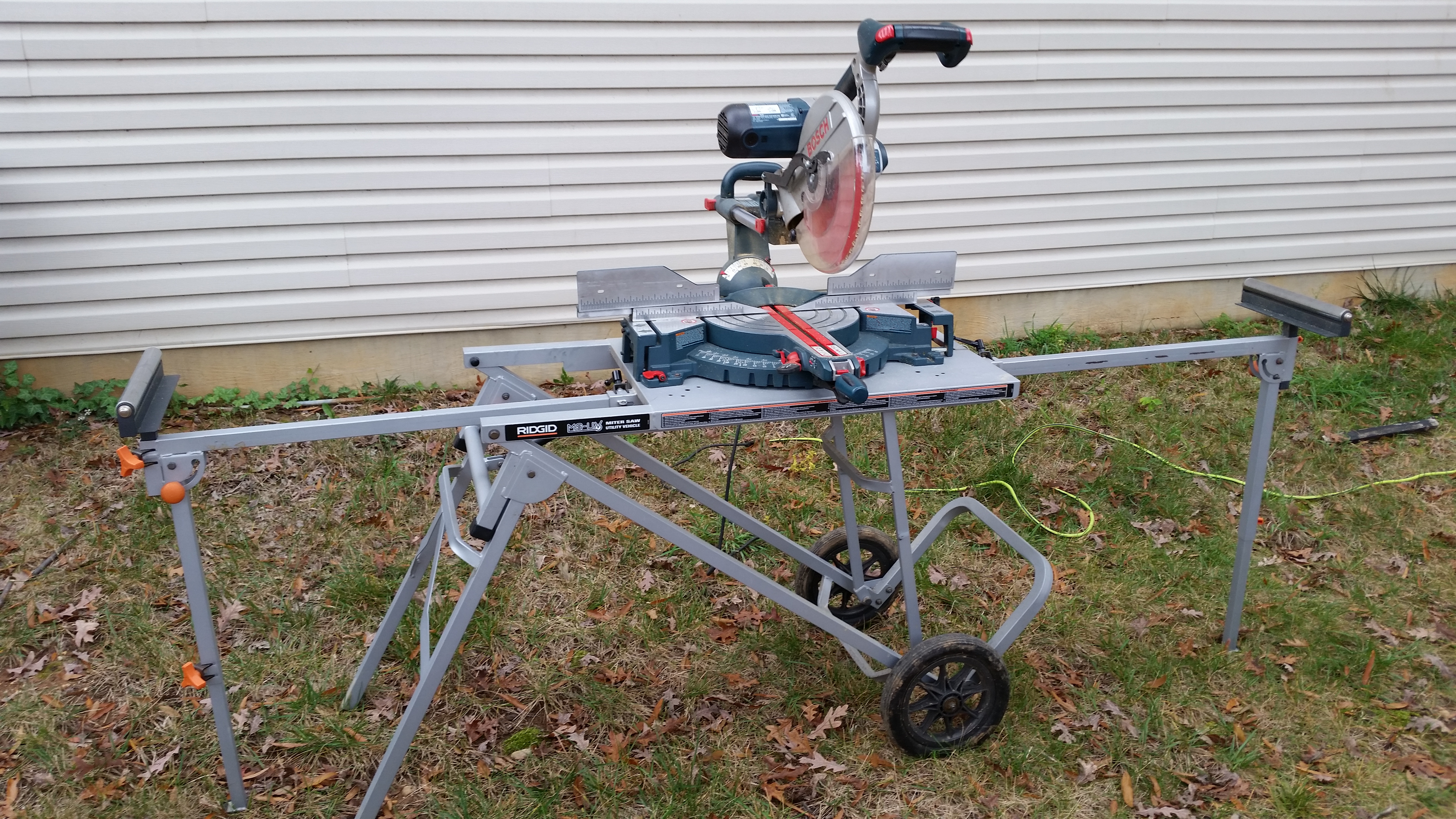
About 6 months ago I called a local steel company and asked them how much it would be to have them cut these for me. They said they didn’t do it and referred me to a local machinist, who wanted nearly $200 to cut the damn things.  Well, a couple of months ago a friend of mine’s elderly father unfortunately passed away and she had the small table saw below that she very graciously gave to me.  Since it was a little beat up and since it’s much more inexpensive than my larger portable table saw, I would use it with a metal cutting blade to cut these 4130 square tubing engine extrusions.
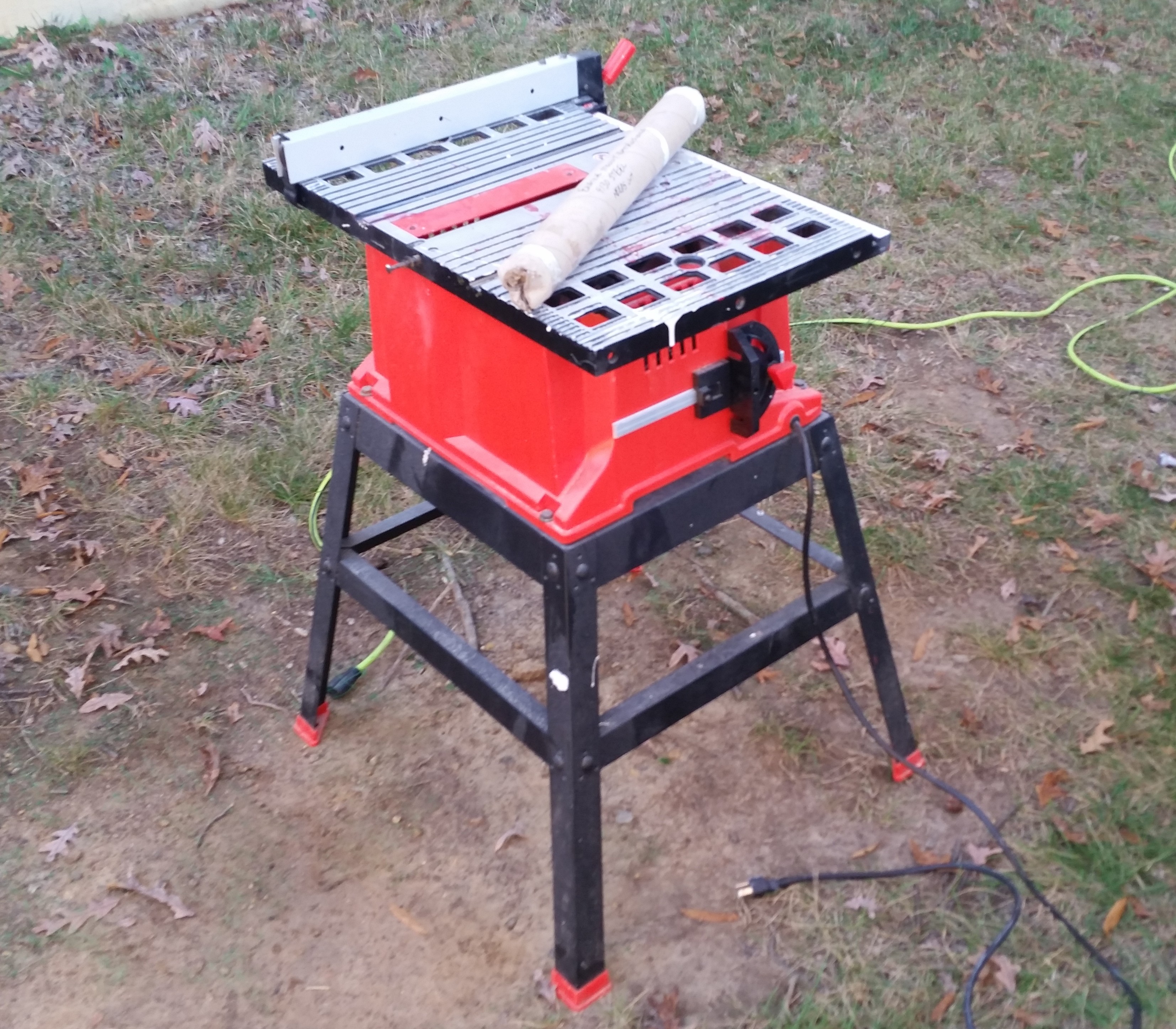
Prepping to cut engine mounts

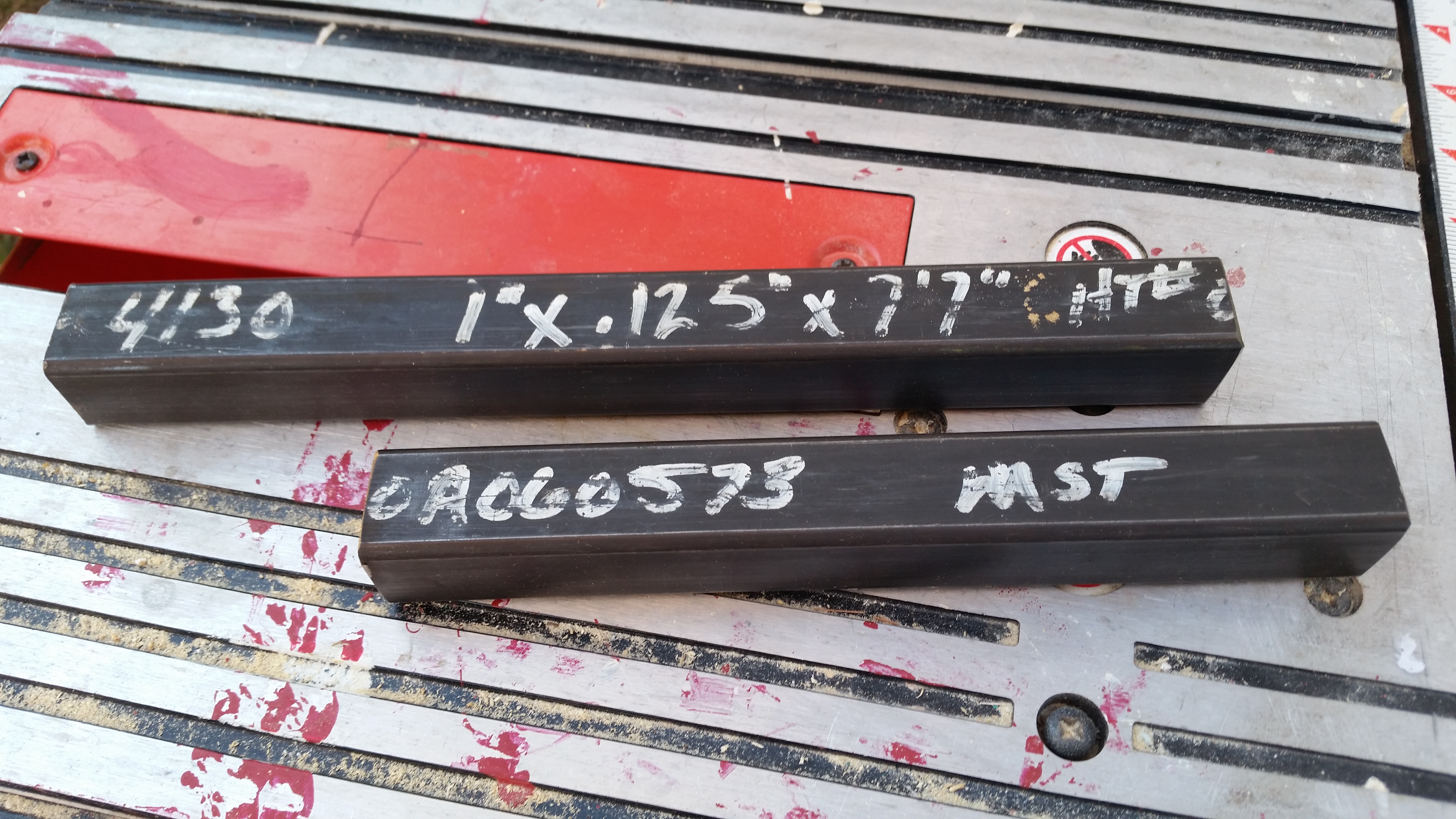
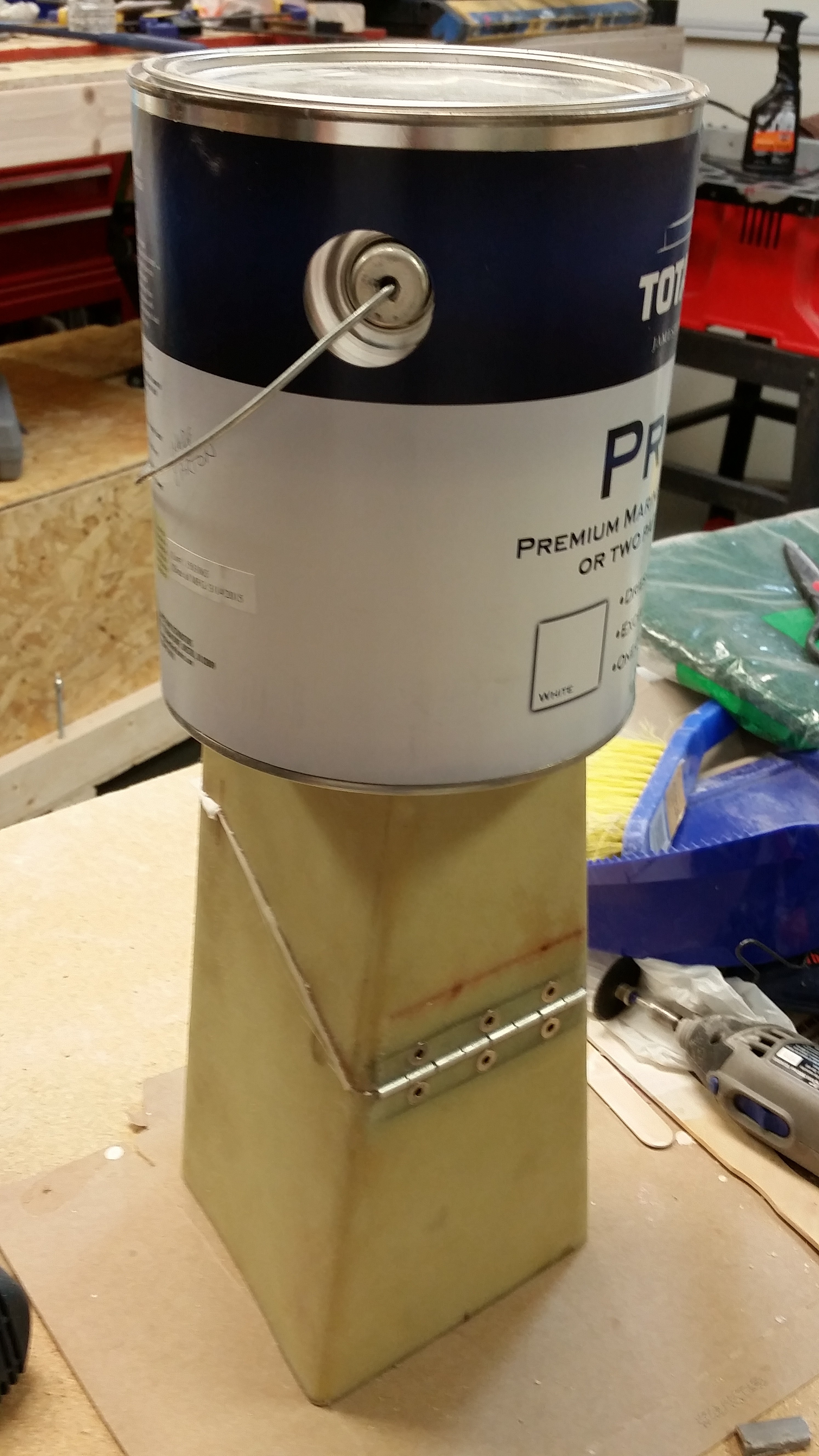
Here’s the square 4130 tubing for the engine mount extrusions.

4130 Engine Mount Extrusions

4130 Engine Mount Extrusions

Ahh, the well laid plans of mice & men!  Unfortunately the blade would flex to the side under the pressure of the hard 4130 steel so it wouldn’t really cut the corners cleanly.  I played around with it for about 15 minutes before finally realizing it was a lesson in futility.  With the corners thinned a bit, I grabbed my Dremel and tried to cut it freehand.  Well, that’s the hardest 4130 steel I’ve seen because by the time I got from one end to the other my Dremel cut bit had disintegrated.

Ok 4130 square tubing!  You won round #1, but I’ll win in the long run!  Ha!  With that, I moved on to more important build tasks at this point in time.

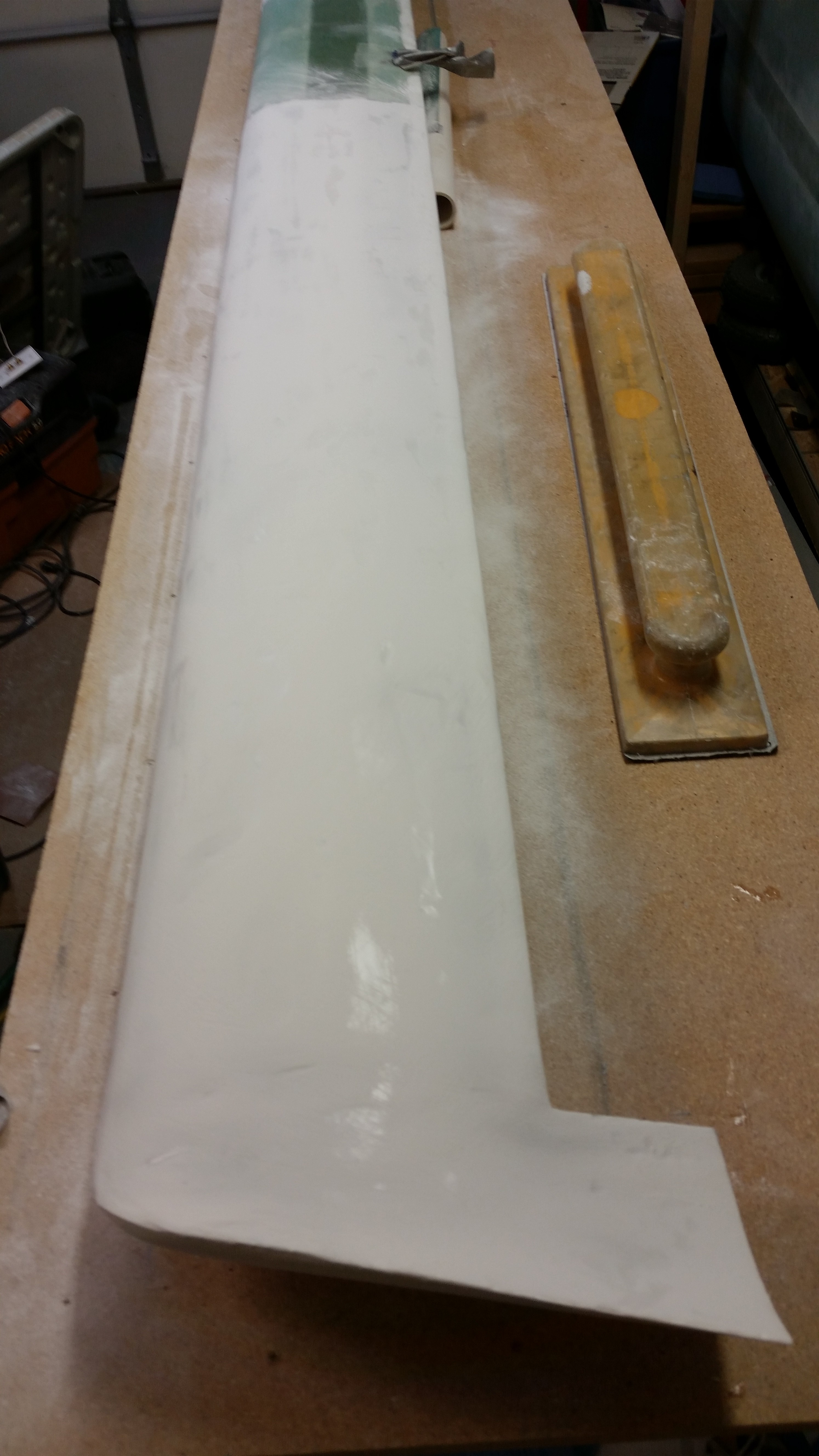
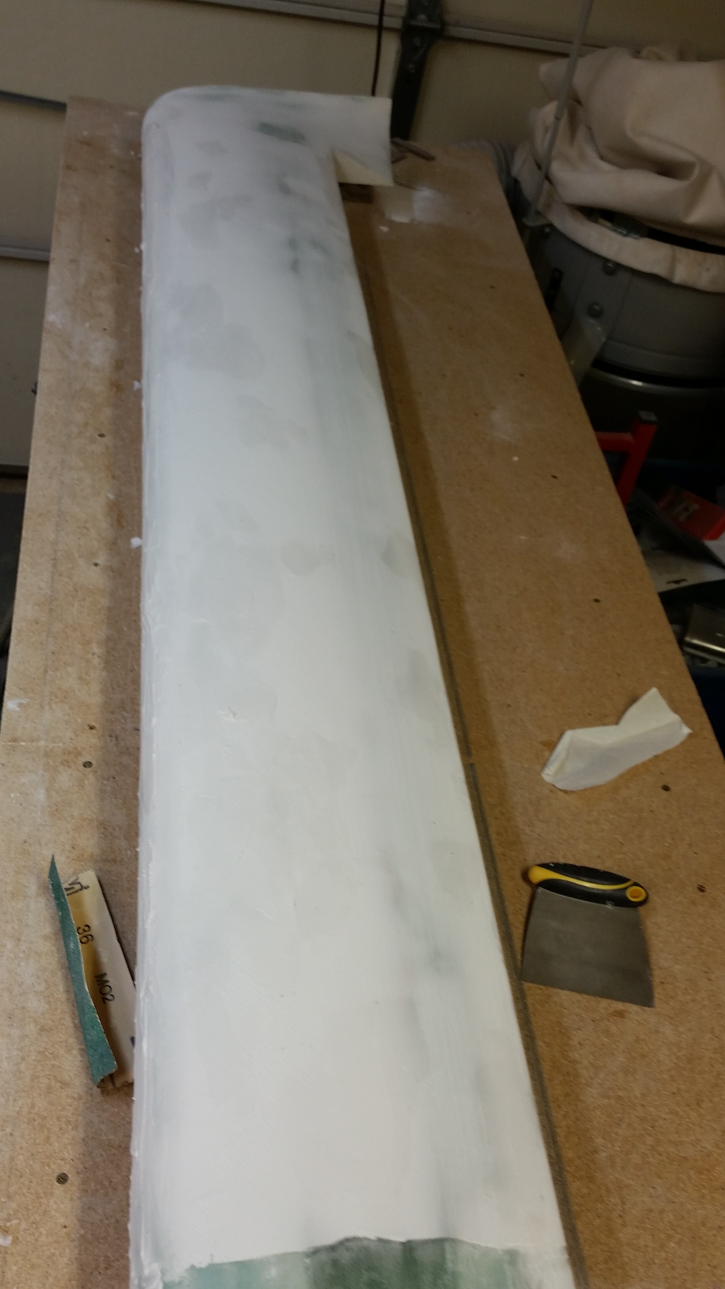
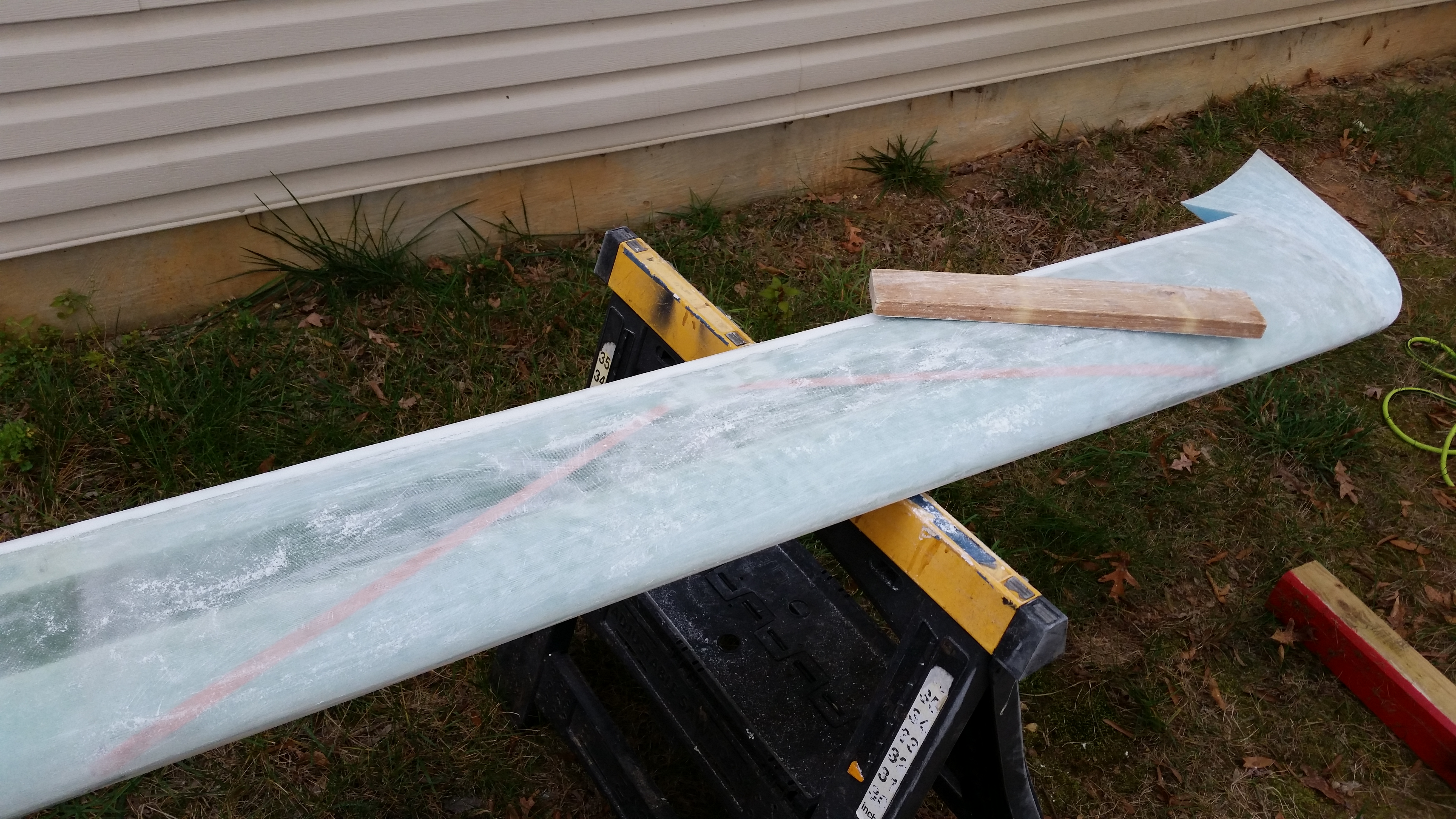
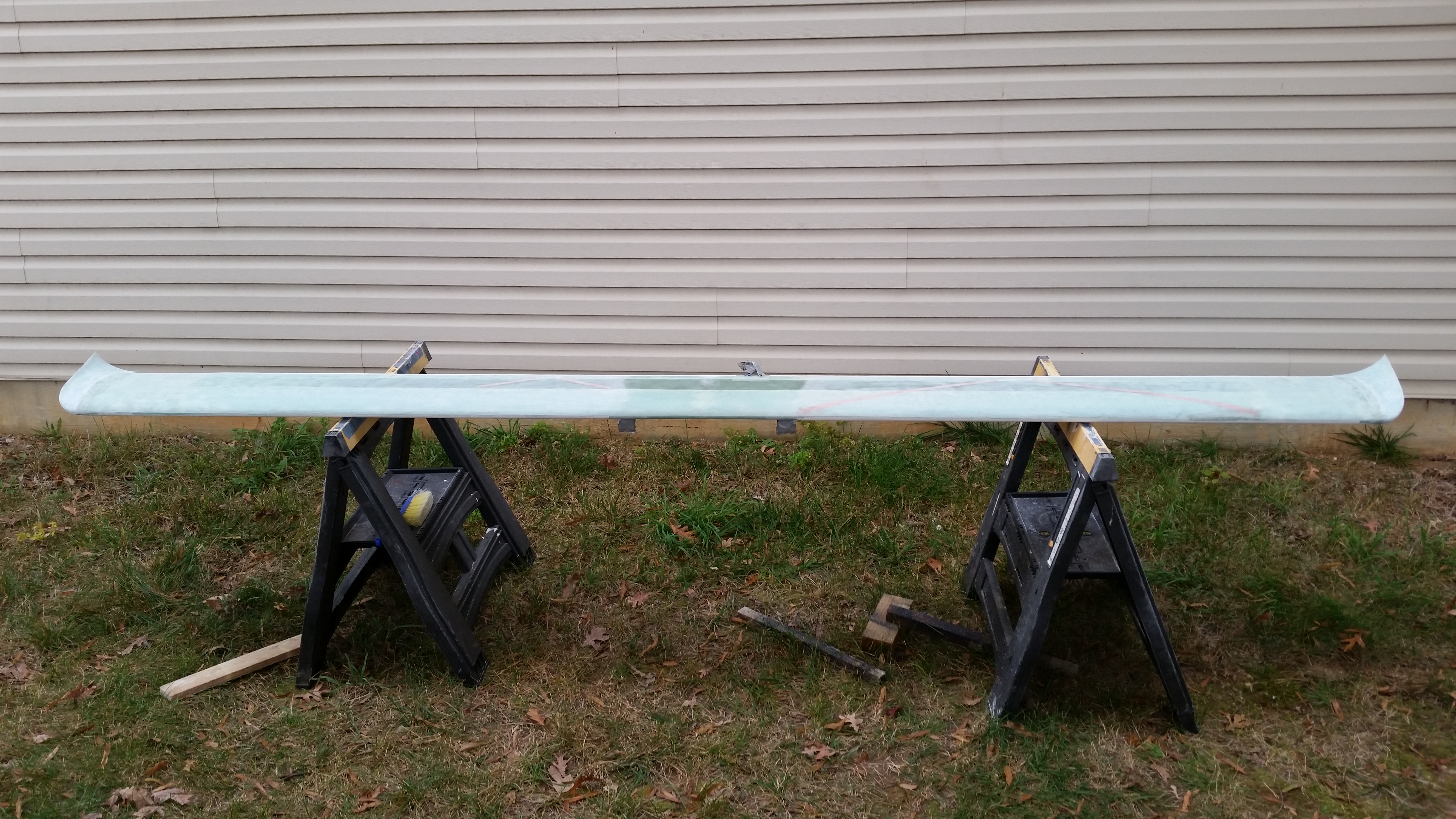
So early in the morning, around 2:30 AM I went down to the work shop to “cheese grate” the micro finish on the canard.  Well, the micro hadn’t fully “greened” yet, so it was still a bit gummy.  I did what I could for about a half hour, but then gave up and went to bed after setting my alarm for 4 AM to get another half hour of “cheese grating” in.  To be honest though, I’ve been exhausted from sanding for hours on end & building the fuselage dolly. Bottom line I slept right through that alarm and missed the “green” state of my micro, so it was nice and cured when I started this afternoon.  You can see that the right side is much more cheese grated than the left.
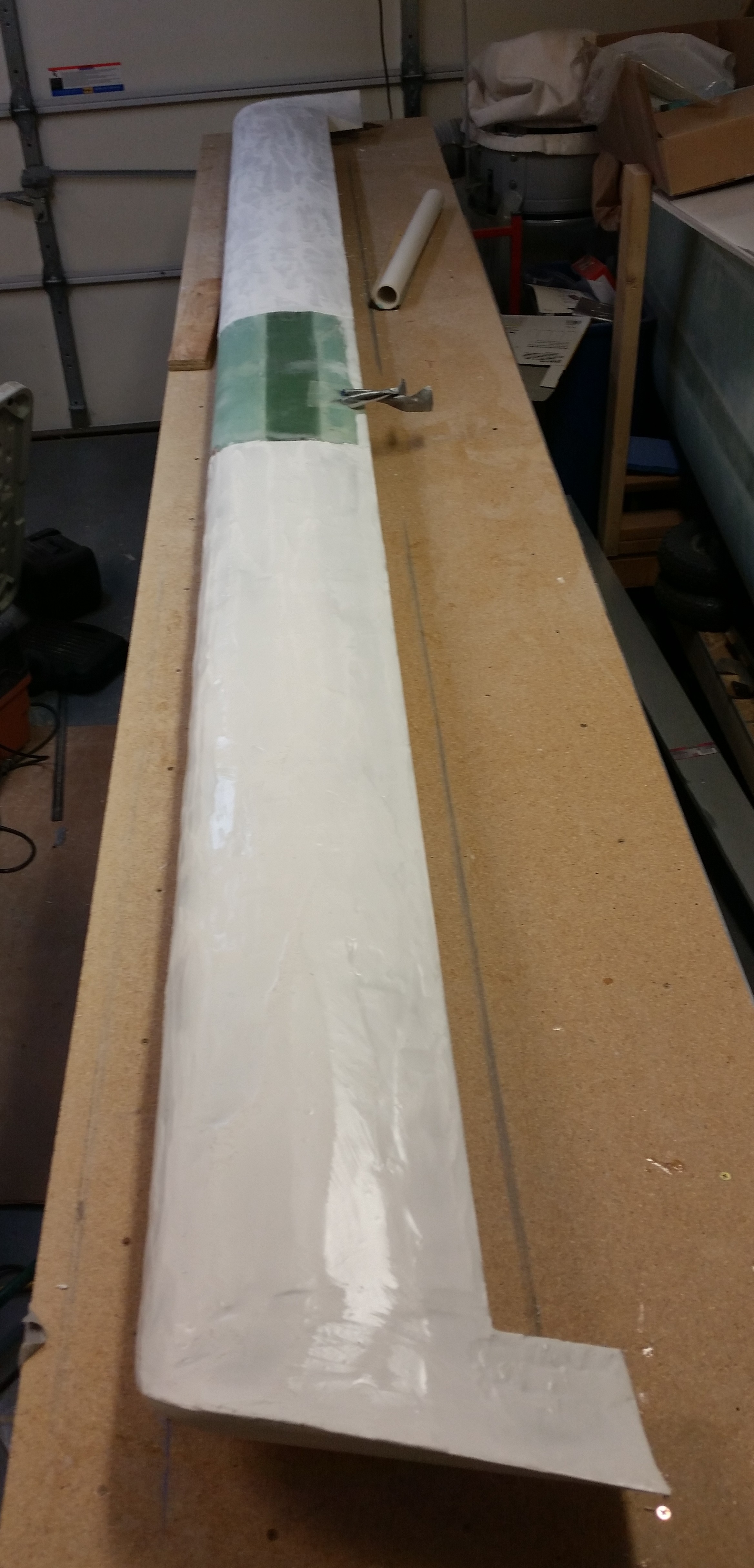
Sanding Canard Micro Finish

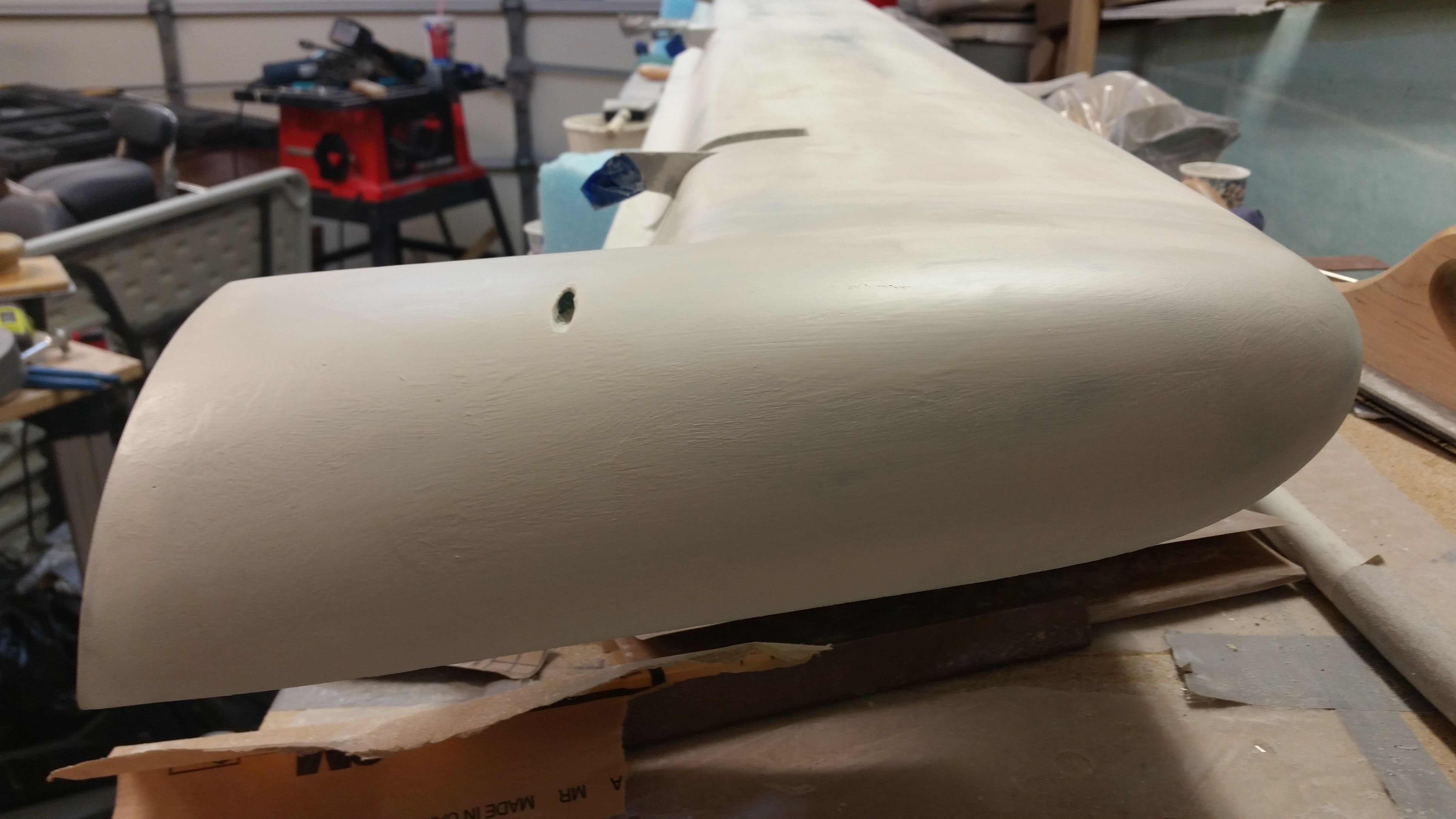
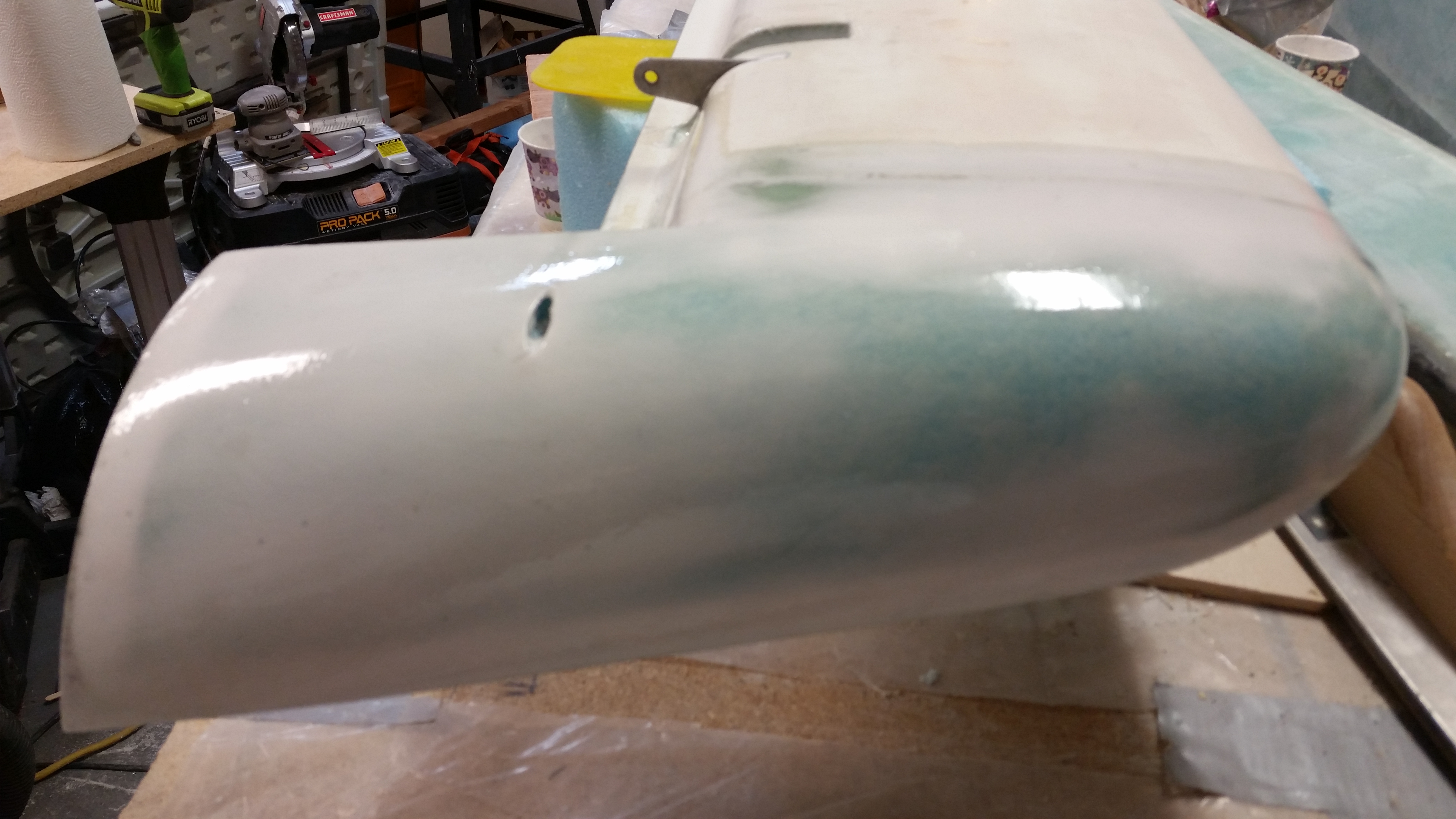
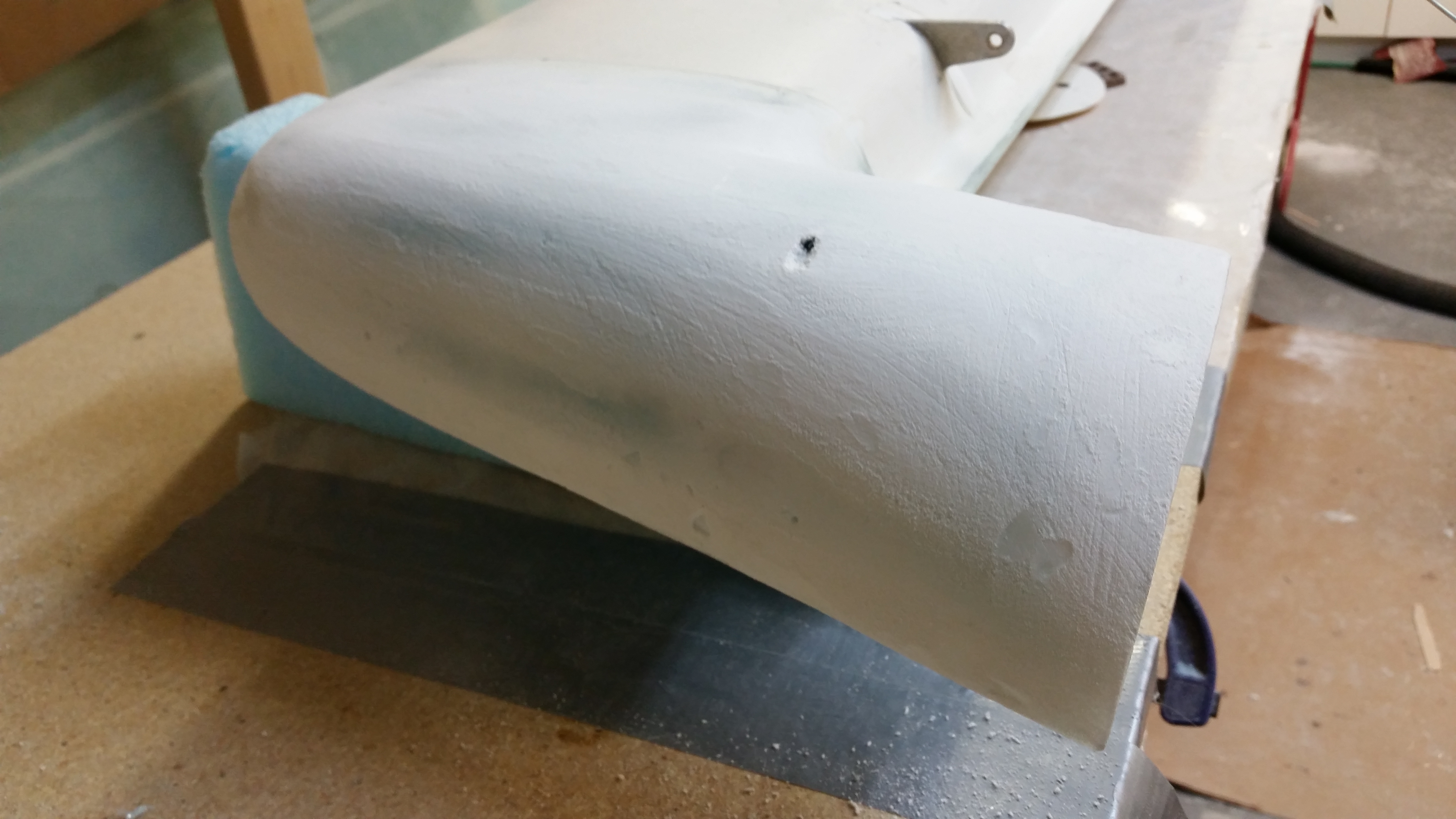
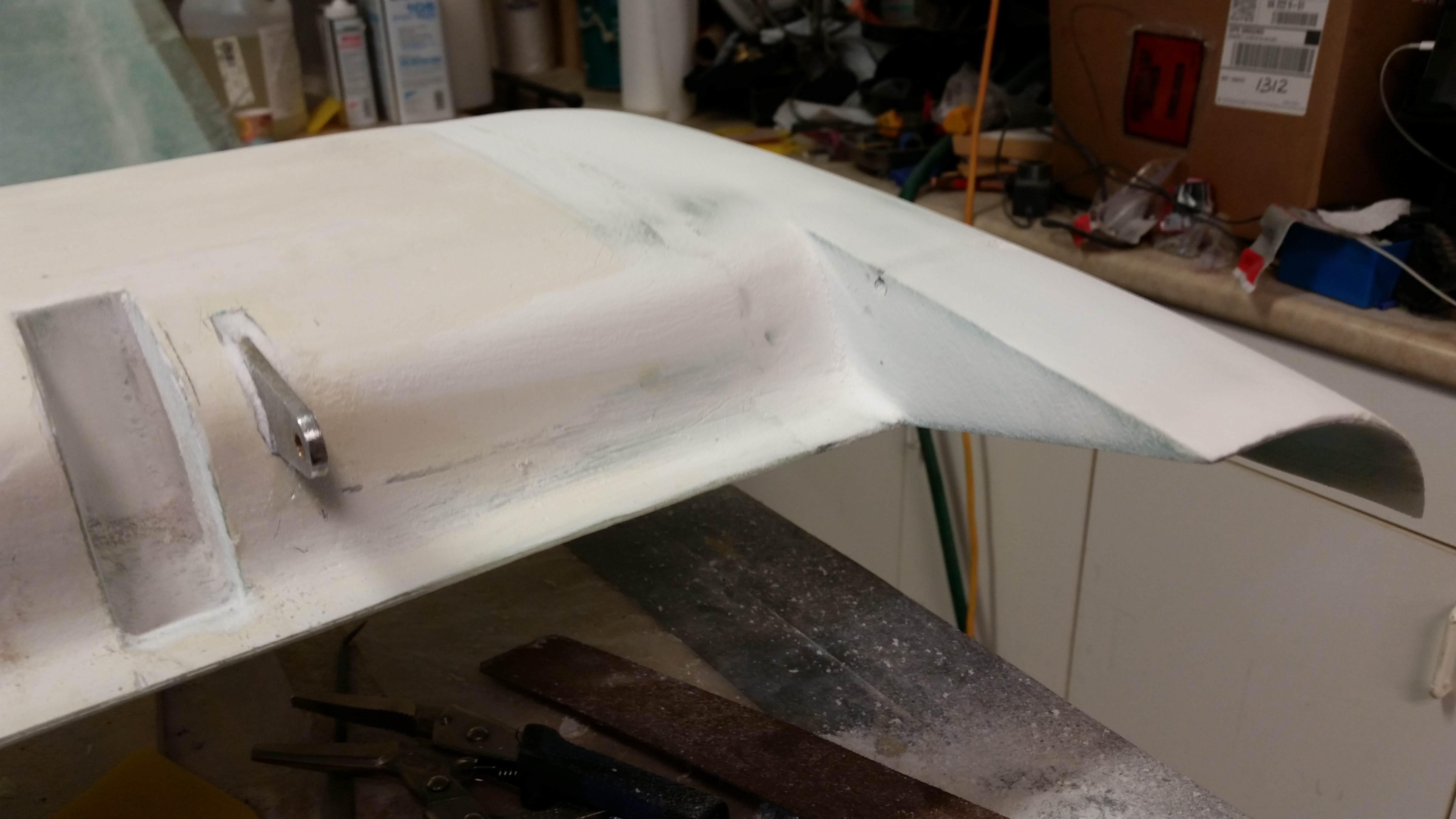
I knocked down the high wave tops of cured micro with the 2″ PVC pipe with 36 grit sandpaper, which is what I used to shape the swoosh tips.  After about 10 minutes with the PVC sanding tube, I moved on to the long sanding board with 36 grit mounted on it.  Again, I sanded for about 10 minutes with the long board.
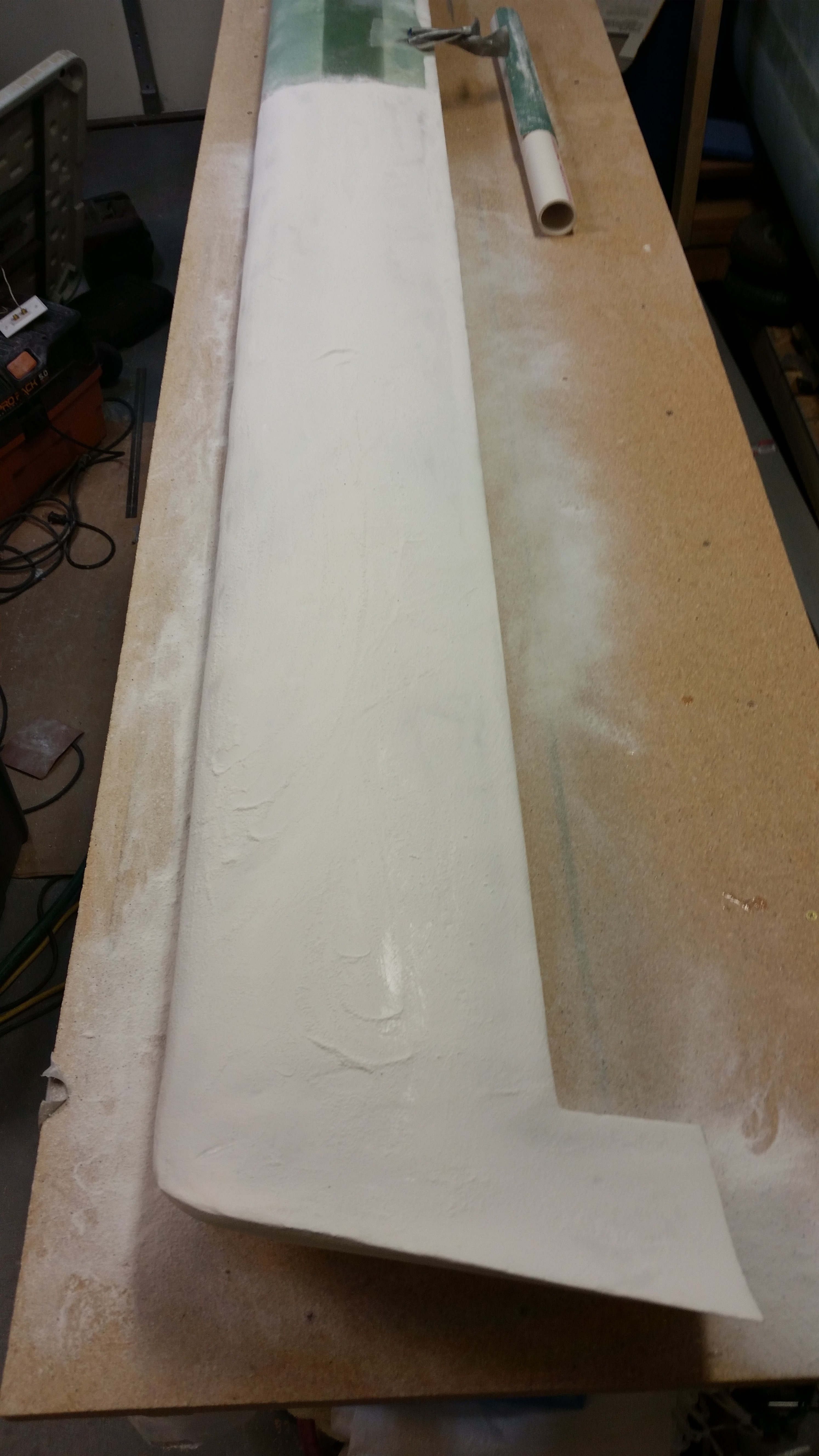
First round sanding with tubeLong board on deck!2nd round sanding with long board


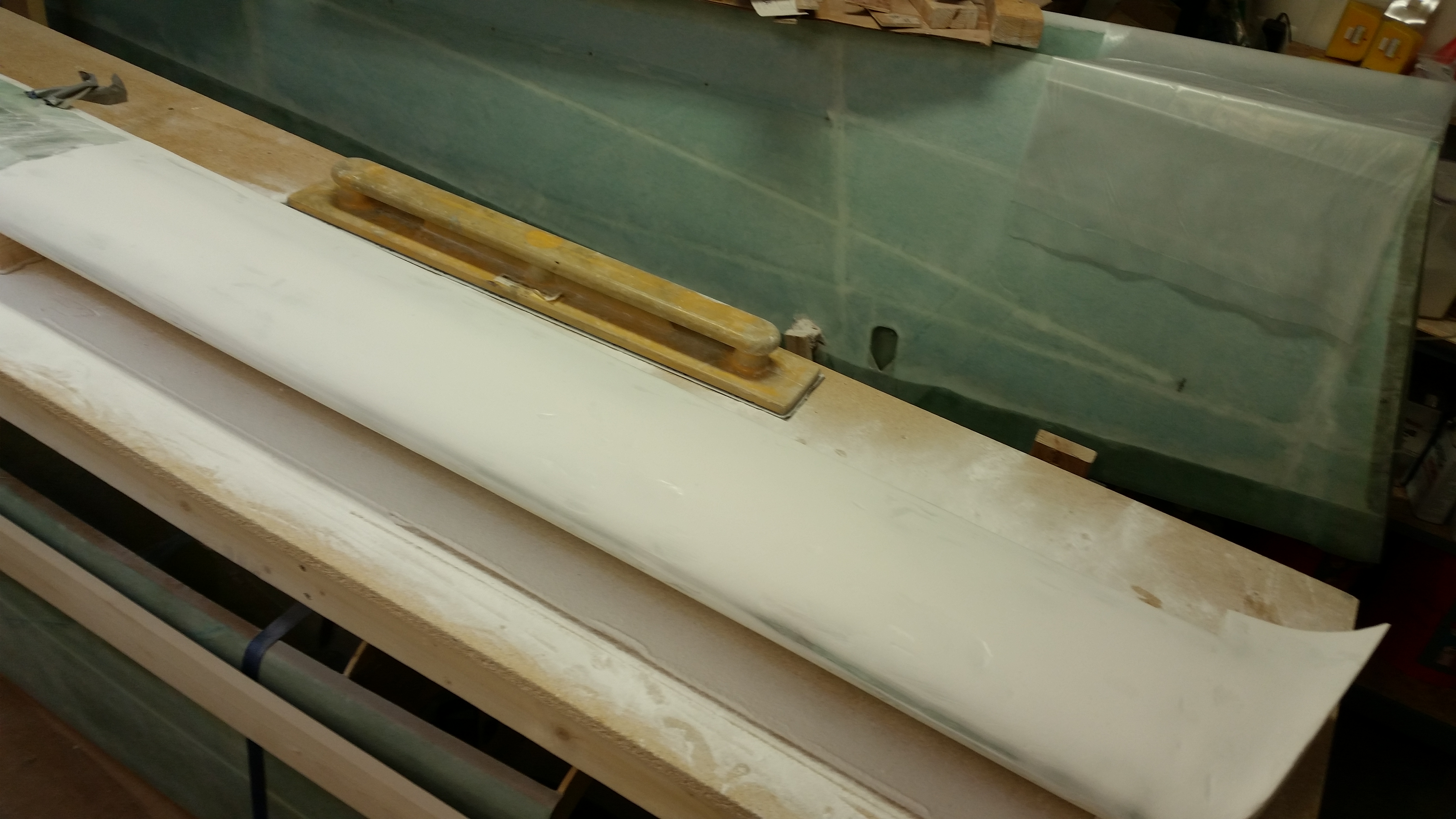
Here’s a shot of the left side of the canard after I sanded it with the long board.
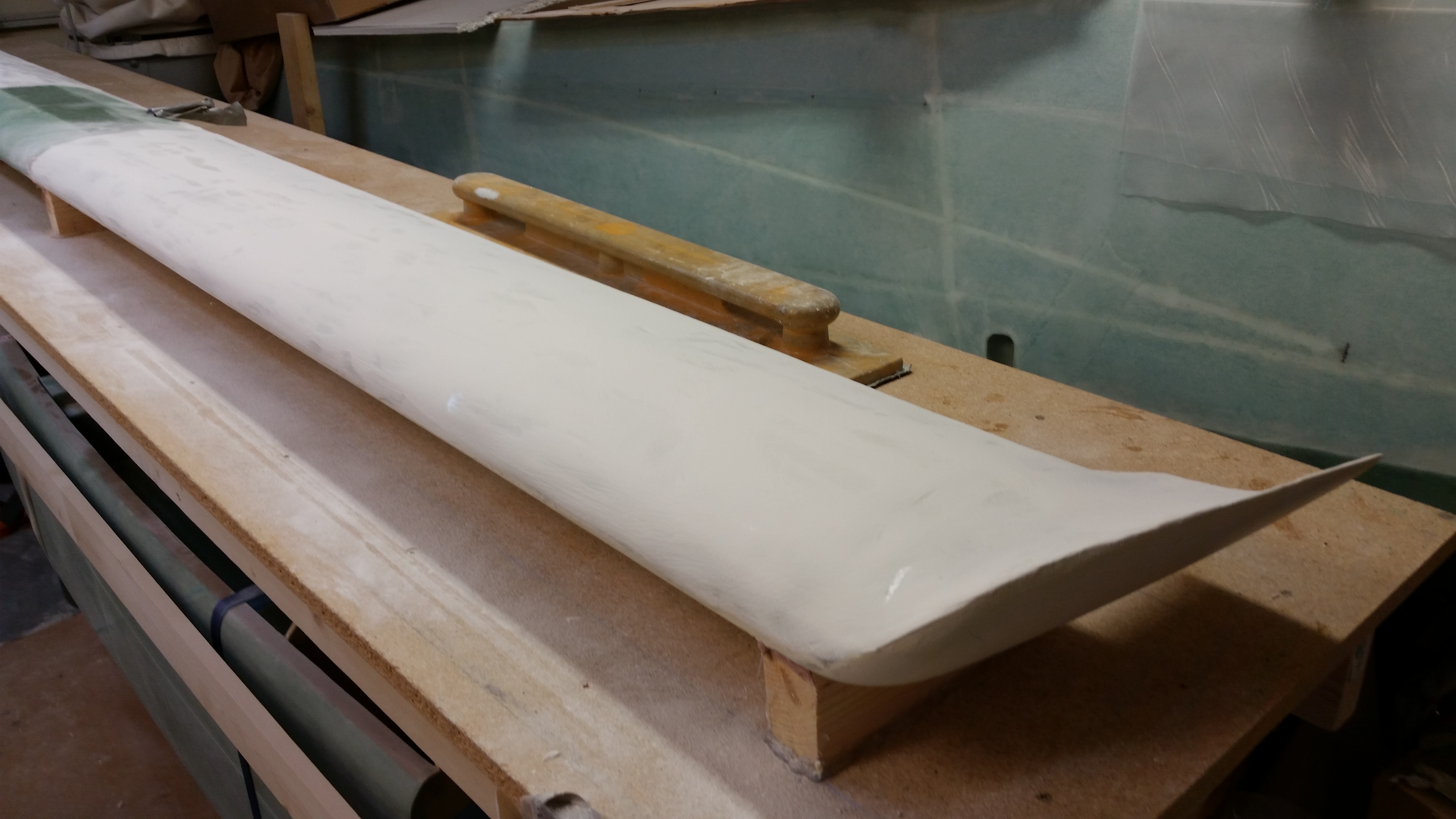
2nd round sanding with long board

After I got the contour somewhat in line, I switched to the contour sanding block with 36 grit sandpaper.
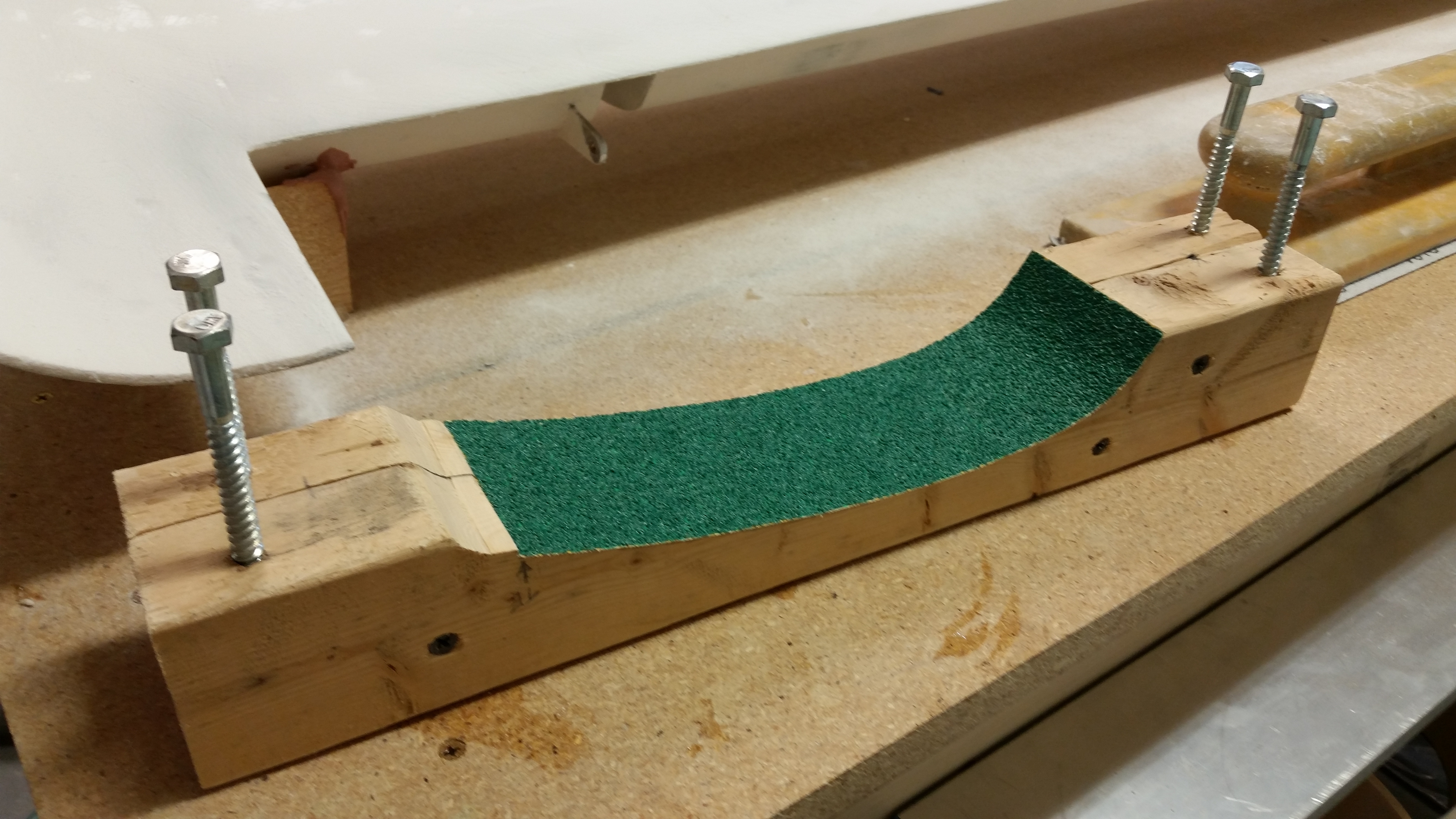
Loading contour sanding block

And here’s a couple shots after I did about 3 good passes (~5 minutes) with the contour sanding block.
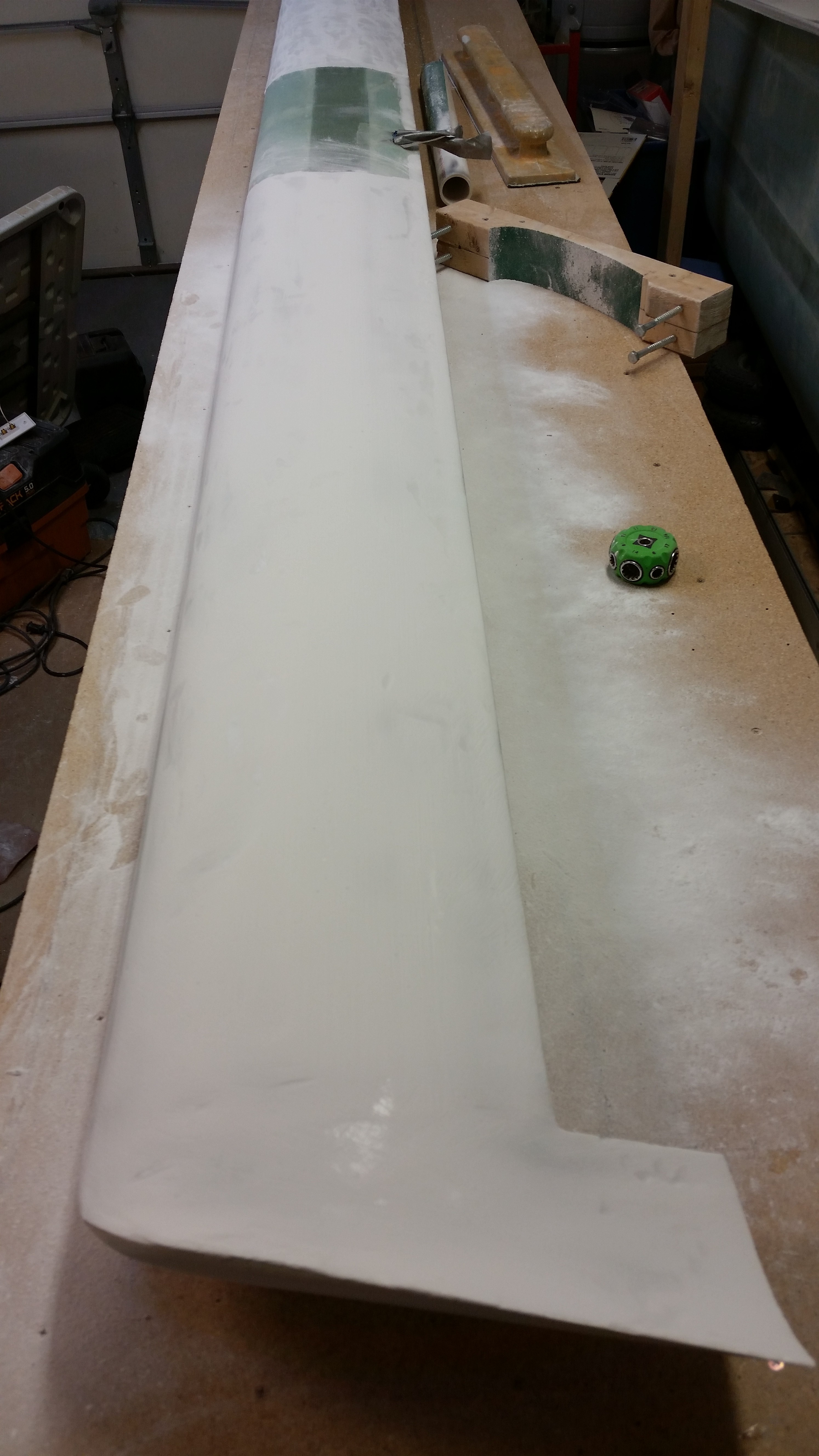
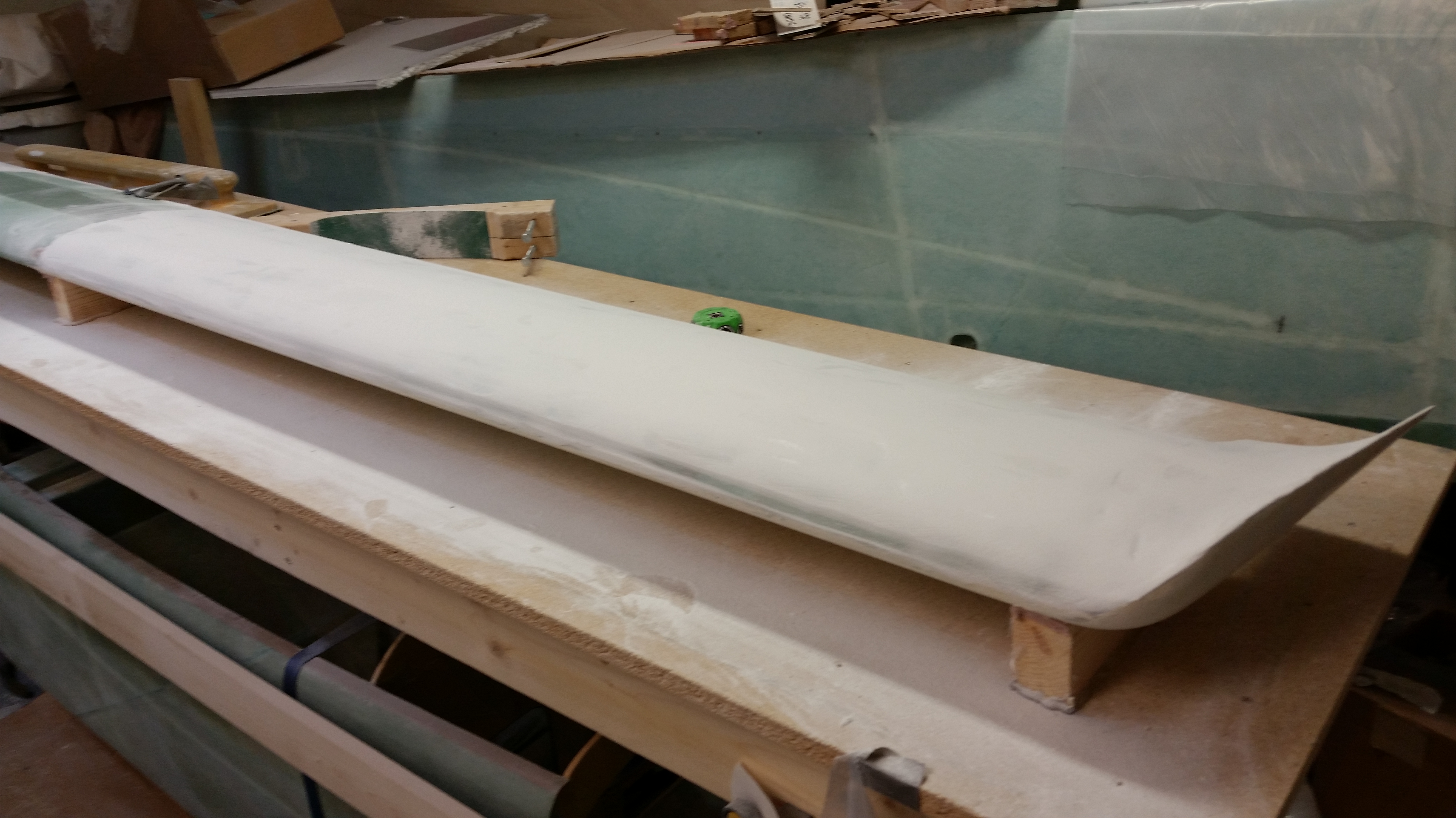
Round 3 - Contour sanding block

Round 3 - Contour sanding block

I then switched back to the long board, using it primarily for the rest of the sanding of the left side top canard surface.  Now, I did do a little hand sanding on the top of the swoosh tip and a did a few more quick passes with the contour sanding block.  Below is a couple more shots after the major sanding on the left side was complete.
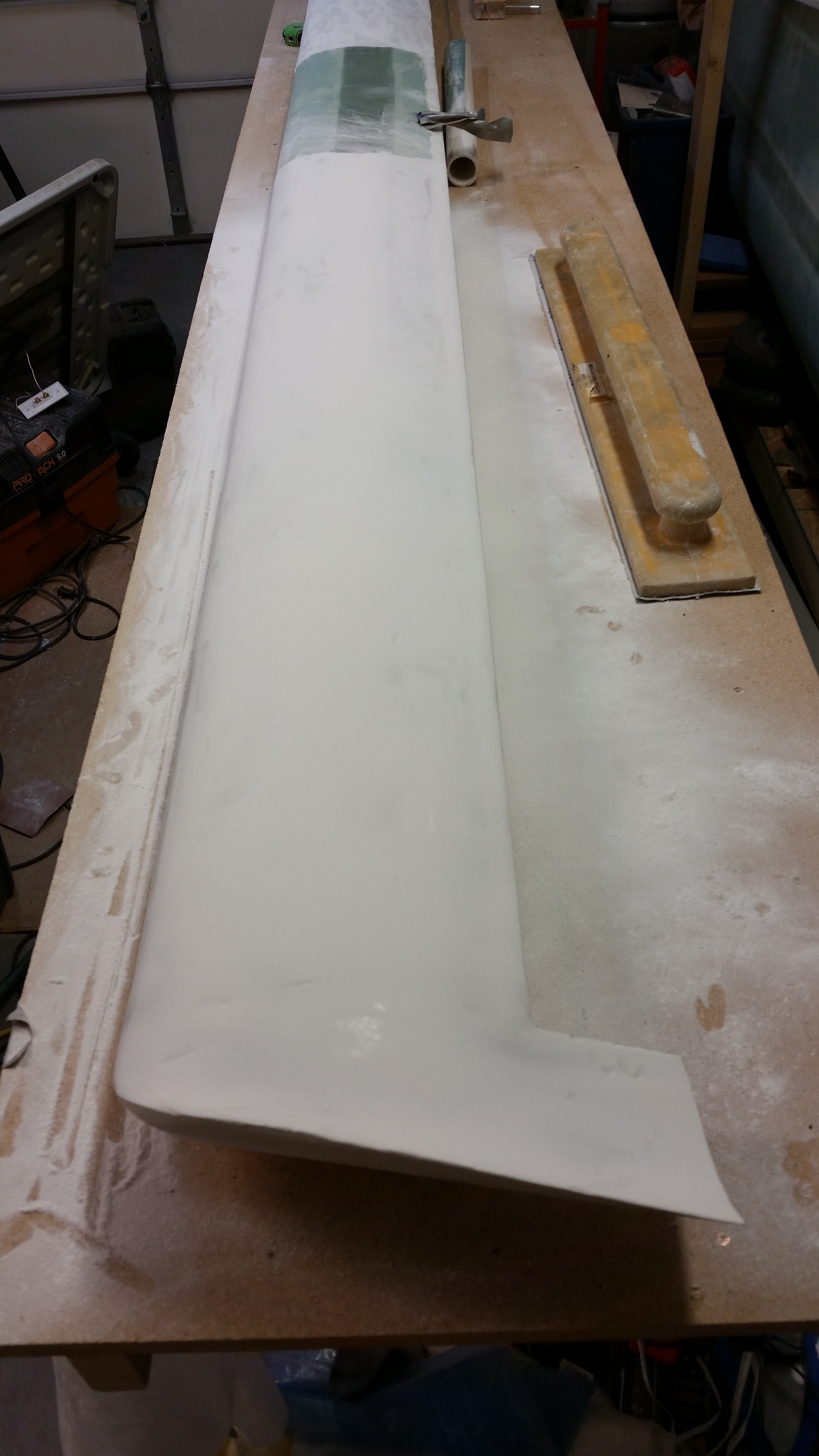
Round 4 - Back to Long Board

Round 4 - Back to Long Board

I then started in on the micro finish on the right side of the canard.  Since I had done a fair amount of cheese grating on the right side, I started with the long sanding board.
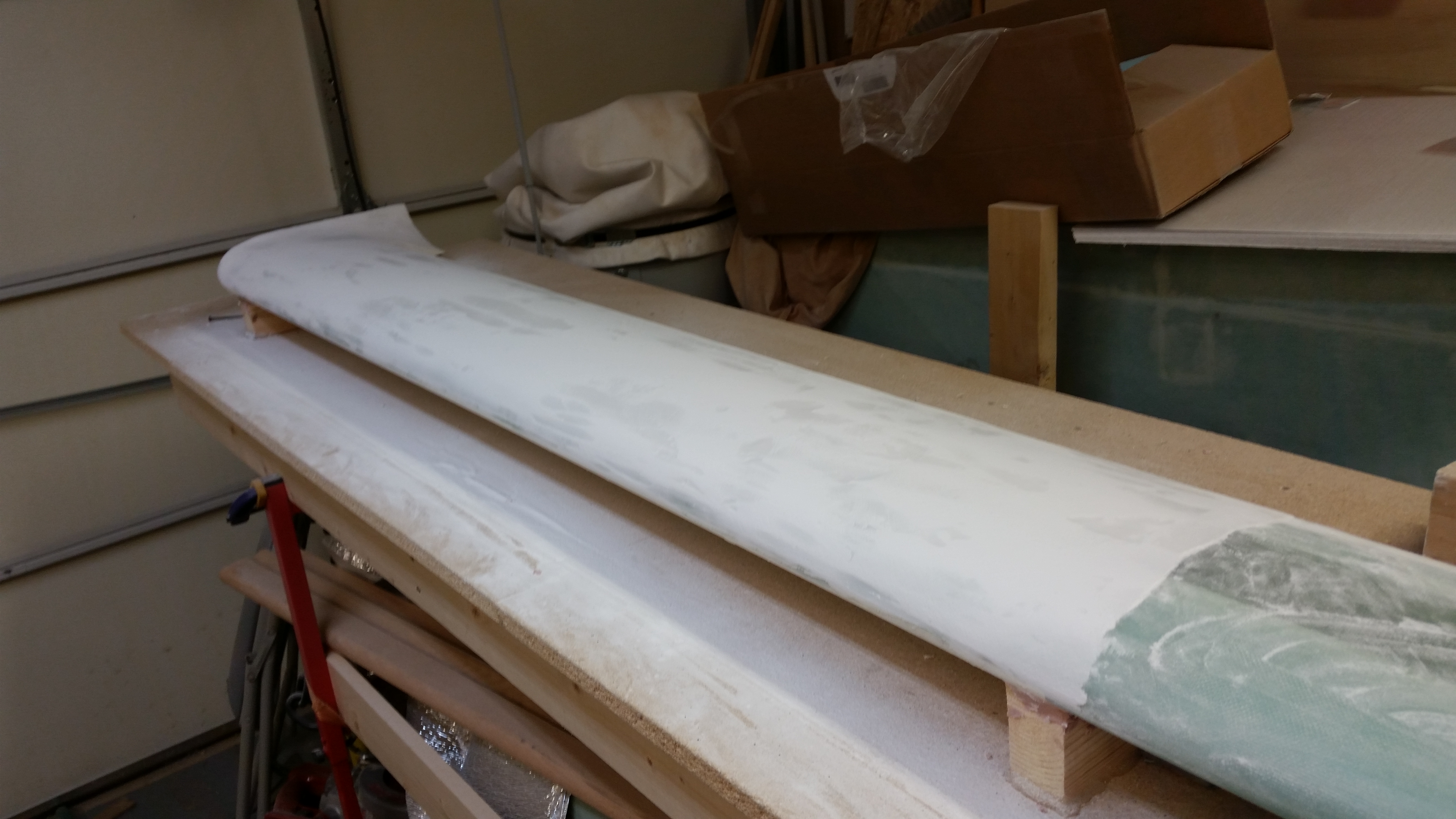
Sanding right side - Long board

After working the long board for a good 10 minutes, I then switched to contour sanding block.  Interestingly, you can see in the pic below that the main contact point for the contour sanding block on the right side was just forward of the TE. Now, I will say that although my canard looks spot on when I sight it by eye, and even run a string on the edges, I think there’s a very slight twist to my canard.  Nothing major, but enough to throw some twists (pardon the pun!) into my canard endeavors.
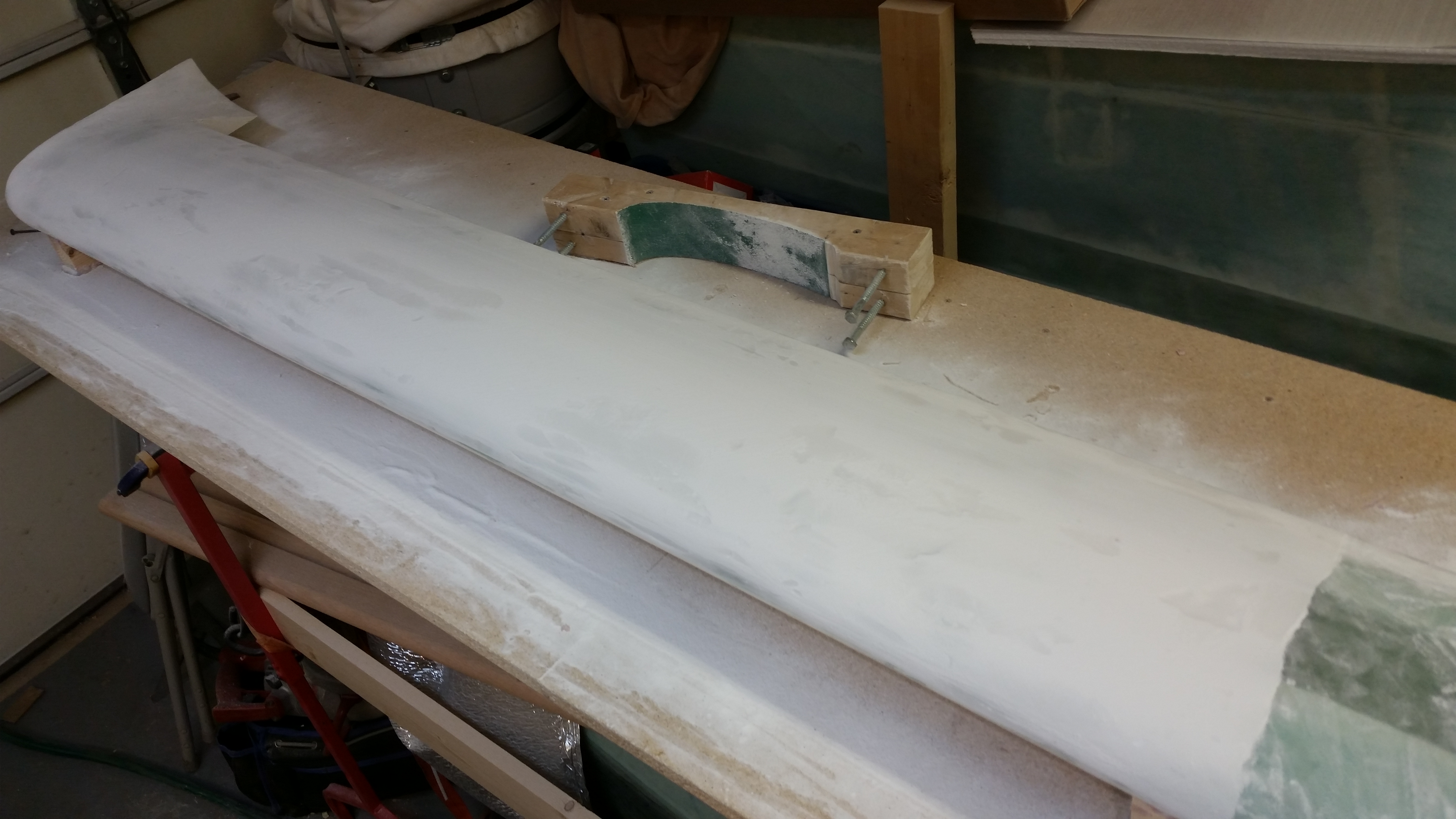
Round 2 - Contour sanding block

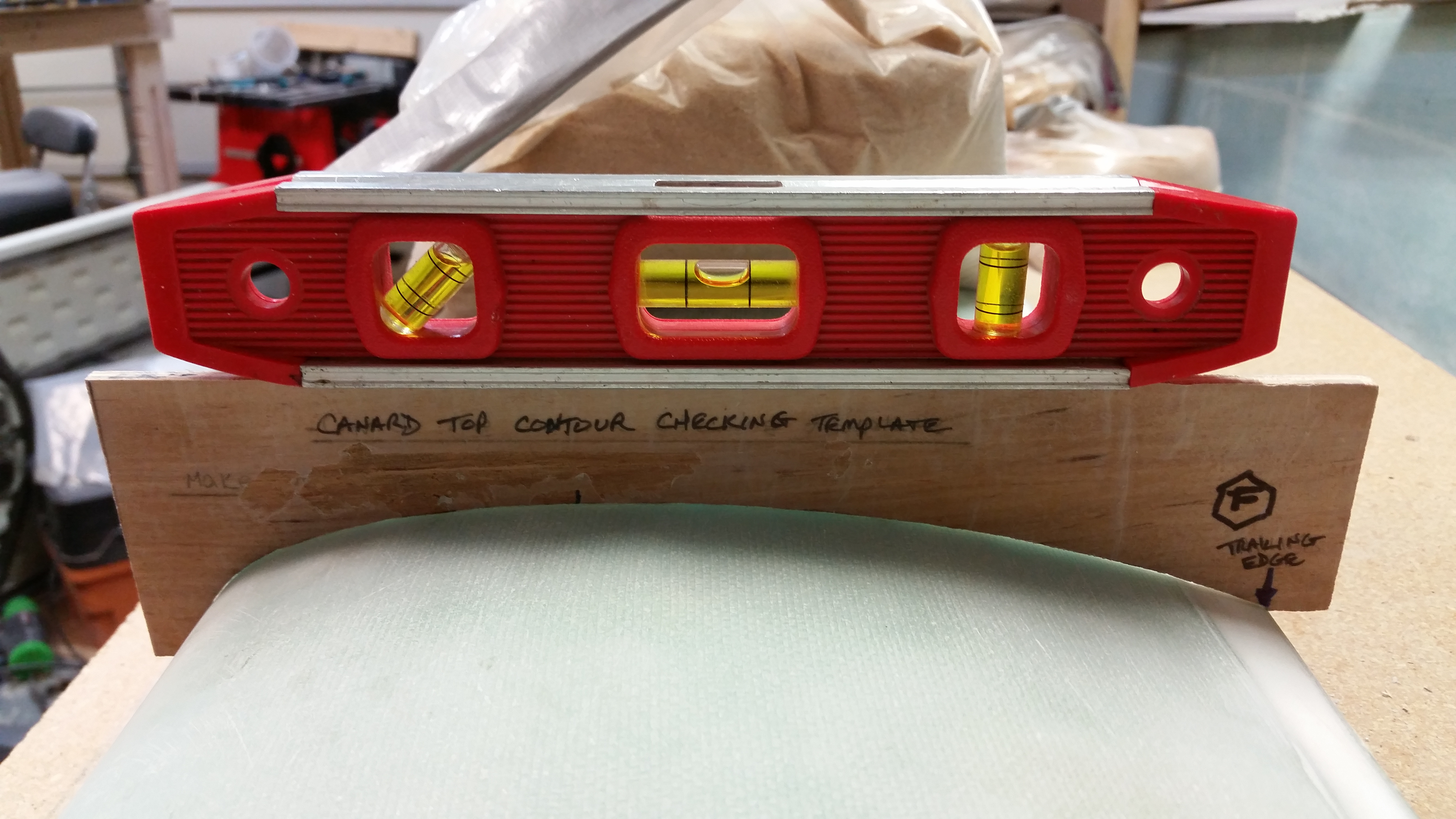
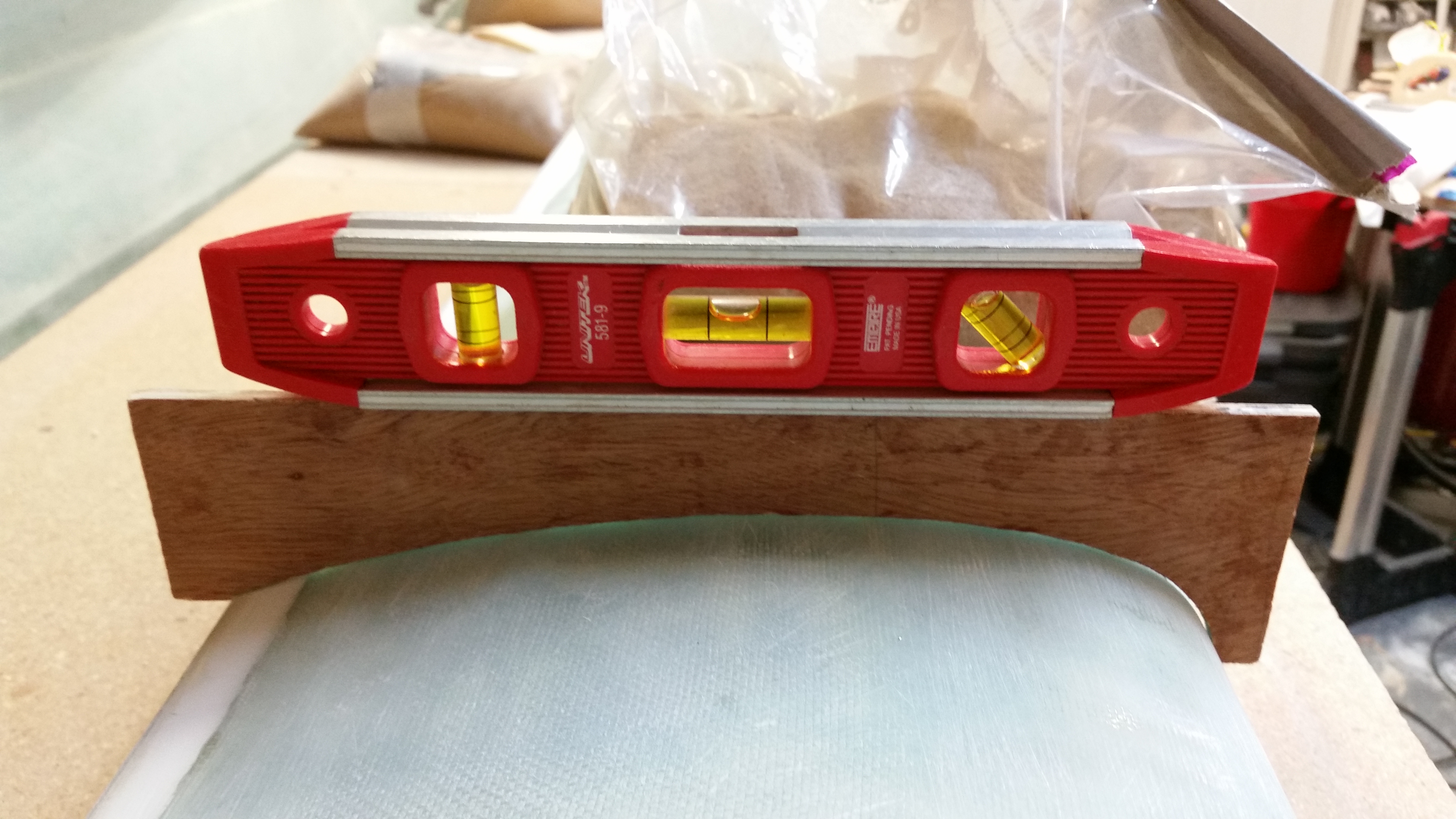
I then checked the top of the canard with the original contour checking template.  Now, in the pic below you probably notice a pink LE.  Before I took this pic I was checking the top canard profile and kept seeing a gap at my LE, in part caused by my contour sanding block digging into the LE edge a bit.  It did get a little of the glass, but not nearly enough to require any glass repair, but I did what something tougher than micro as a foundation so I slathered on a thick layer of Bondo onto the outer 2/3rds of the left side LE.

Since Bondo cures so quickly, after working for a bit on the right side I came back and quickly sanded the Bondo.  Now, I know Bondo is heavier, but the resulting sanded layer averages around 30 thou (0.030″) thick.  Like I said, it’s enough to give a little depth and a little harder base that can’t get sanded off so quickly.  I’m really seeing that both the trailing & leading edges can go uglier fast, so due diligence to these areas is a must.
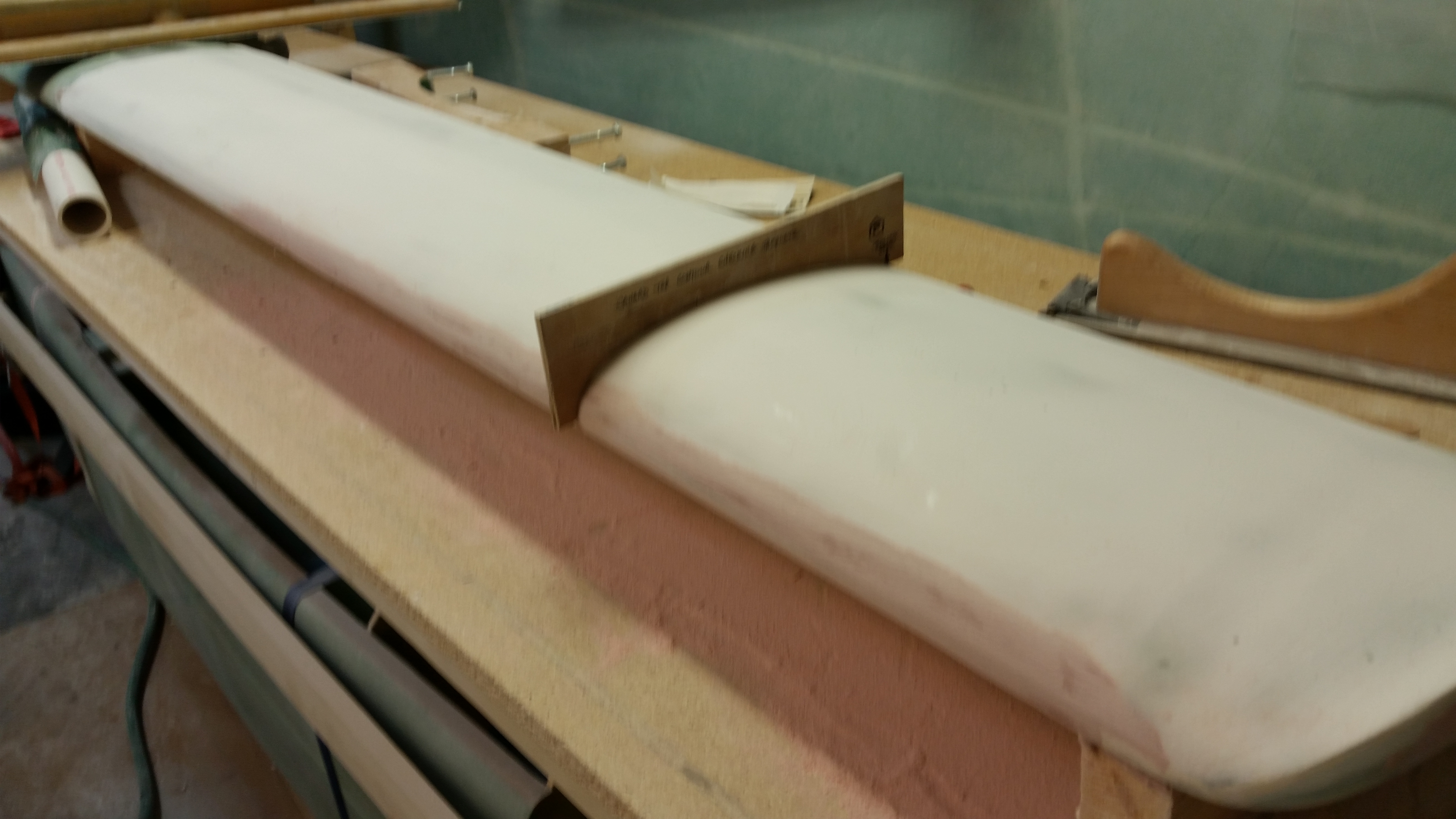
Checking contour profile

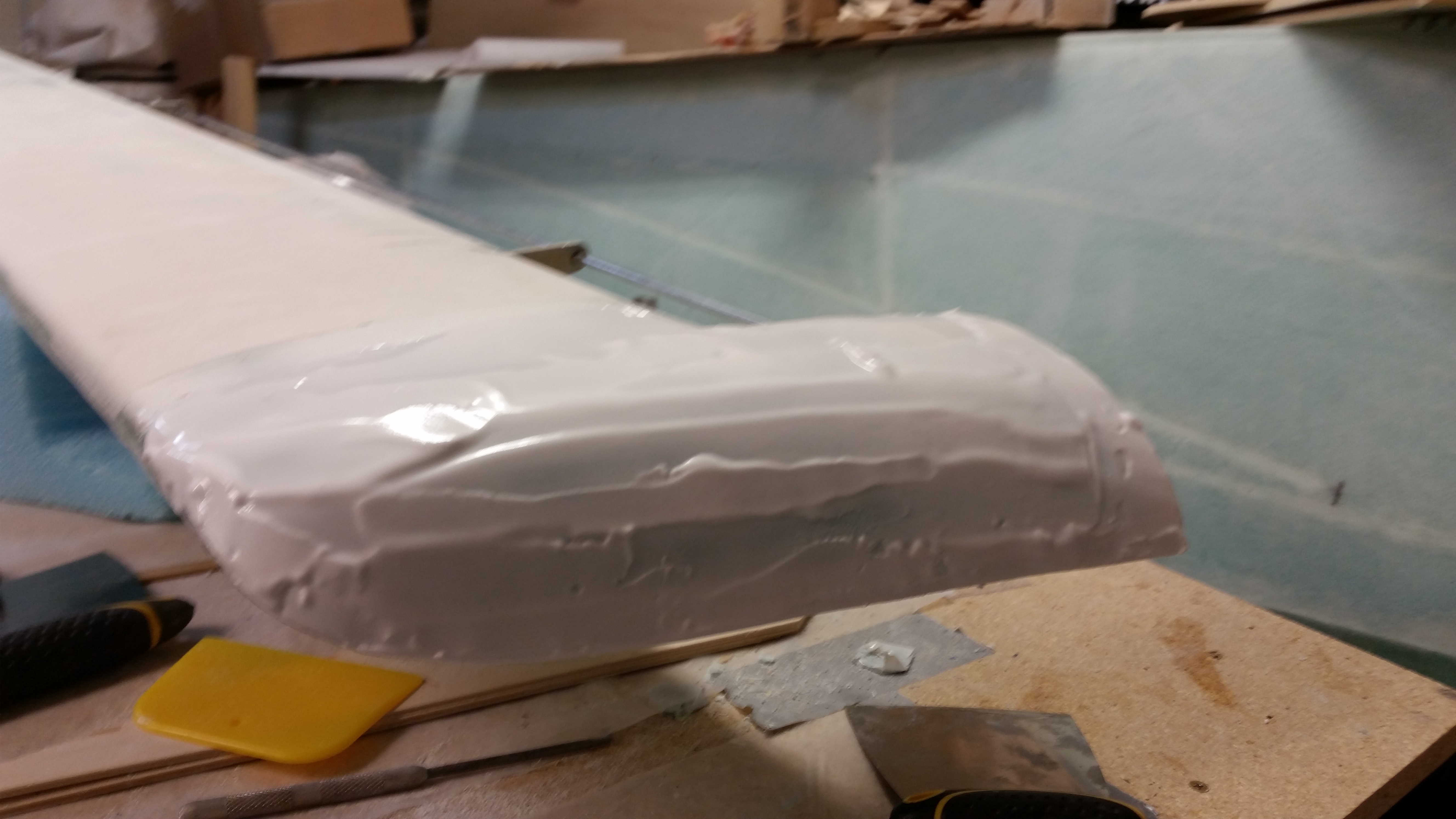
I then violated one of the laws of the finishing composites by adding a second round of micro to fill in the low points on both sides (left/right, top) of the canard, and also slather a bunch on the LE on both sides to build that up to better get the plans LE shape as close as possible.
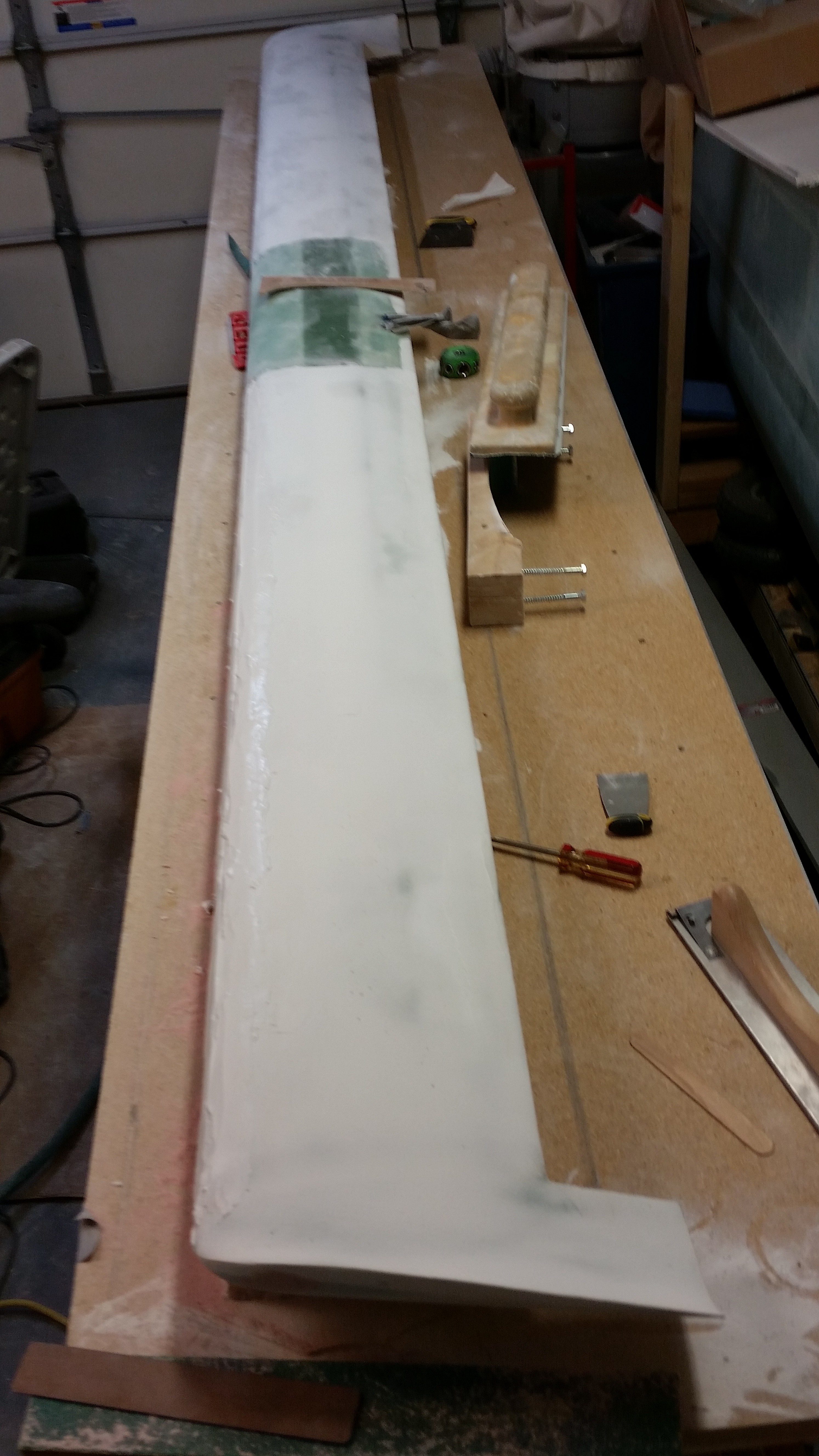
Second round of micro

Early on I was aggressively shaping the left outboard/bottom swoosh tip when I got to glass, and broke through to the inner layer of glass.  With the glass thin at this point, when I mixed up the Bondo, swabbed some on that area too to beef it up just a bit more.
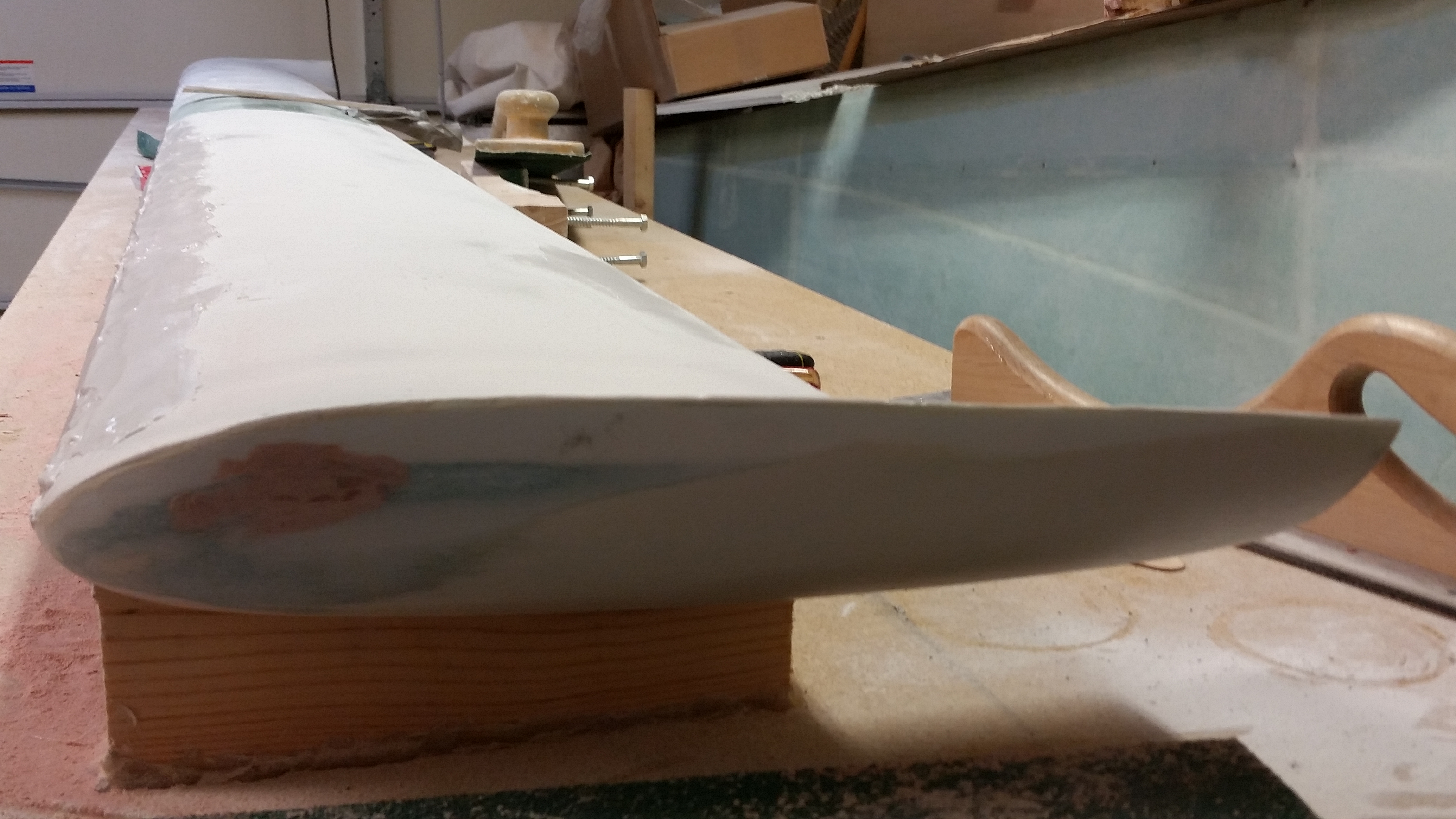
Bond on swoosh tip thin spot

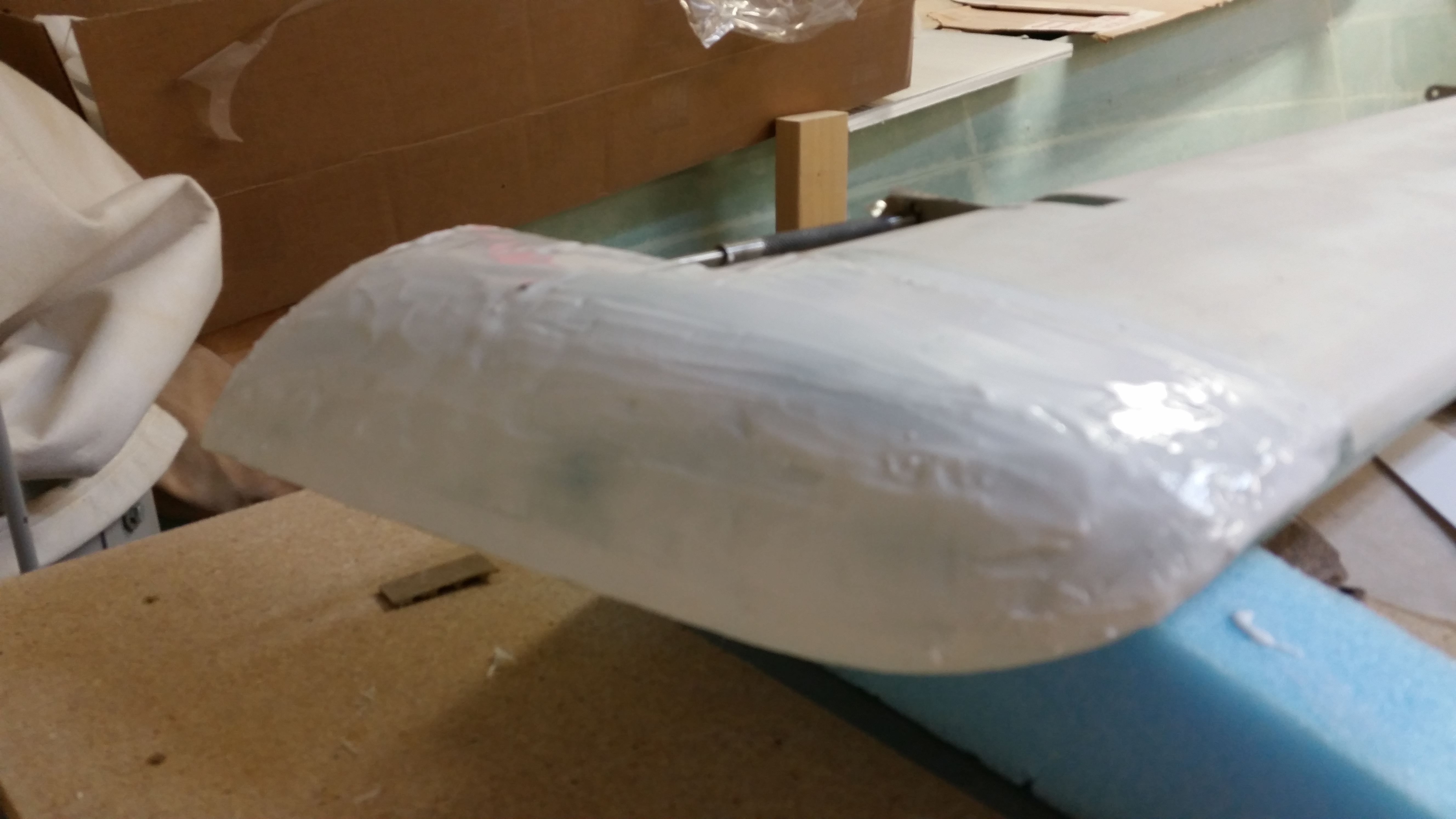
Here’s a couple shots of micro round 2.

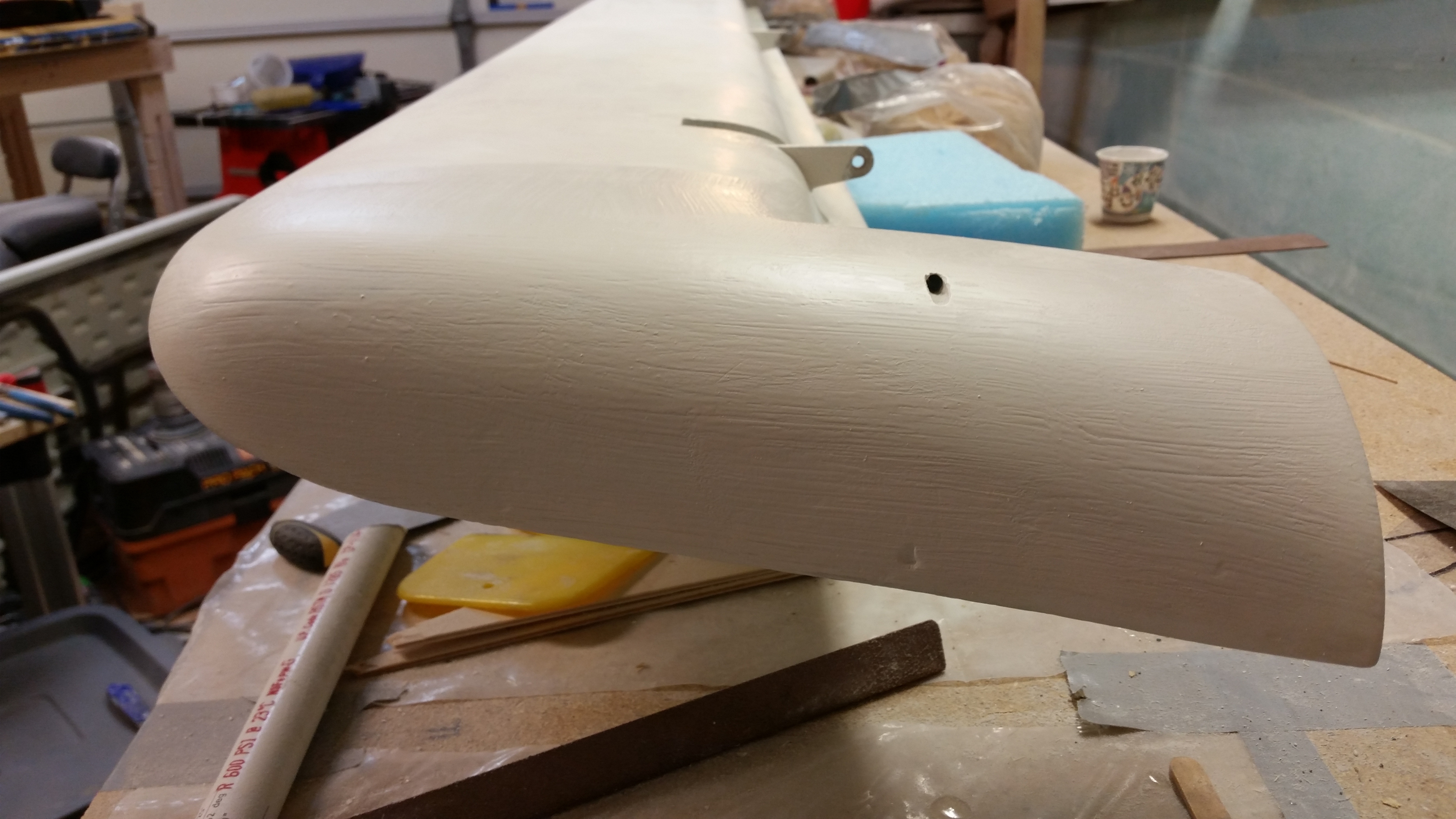
Left side LE - Micro over bondo

Right side - remicro'd

Of course I mixed up too much micro and expecting at one point that this might be the case, I implemented my ancillary plan and Dremeled out the foam on the edges of the headrest halves.
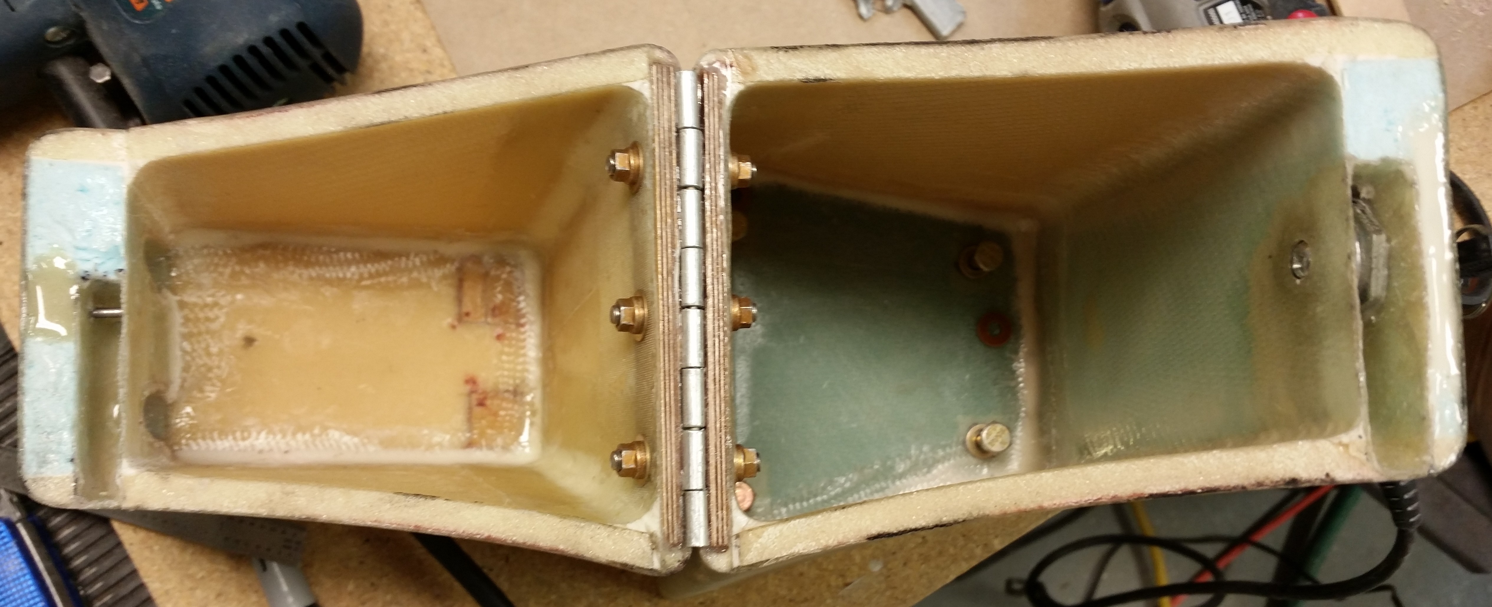
Removing headrest edge foam

Here’s the micro applied to the headrest edges.
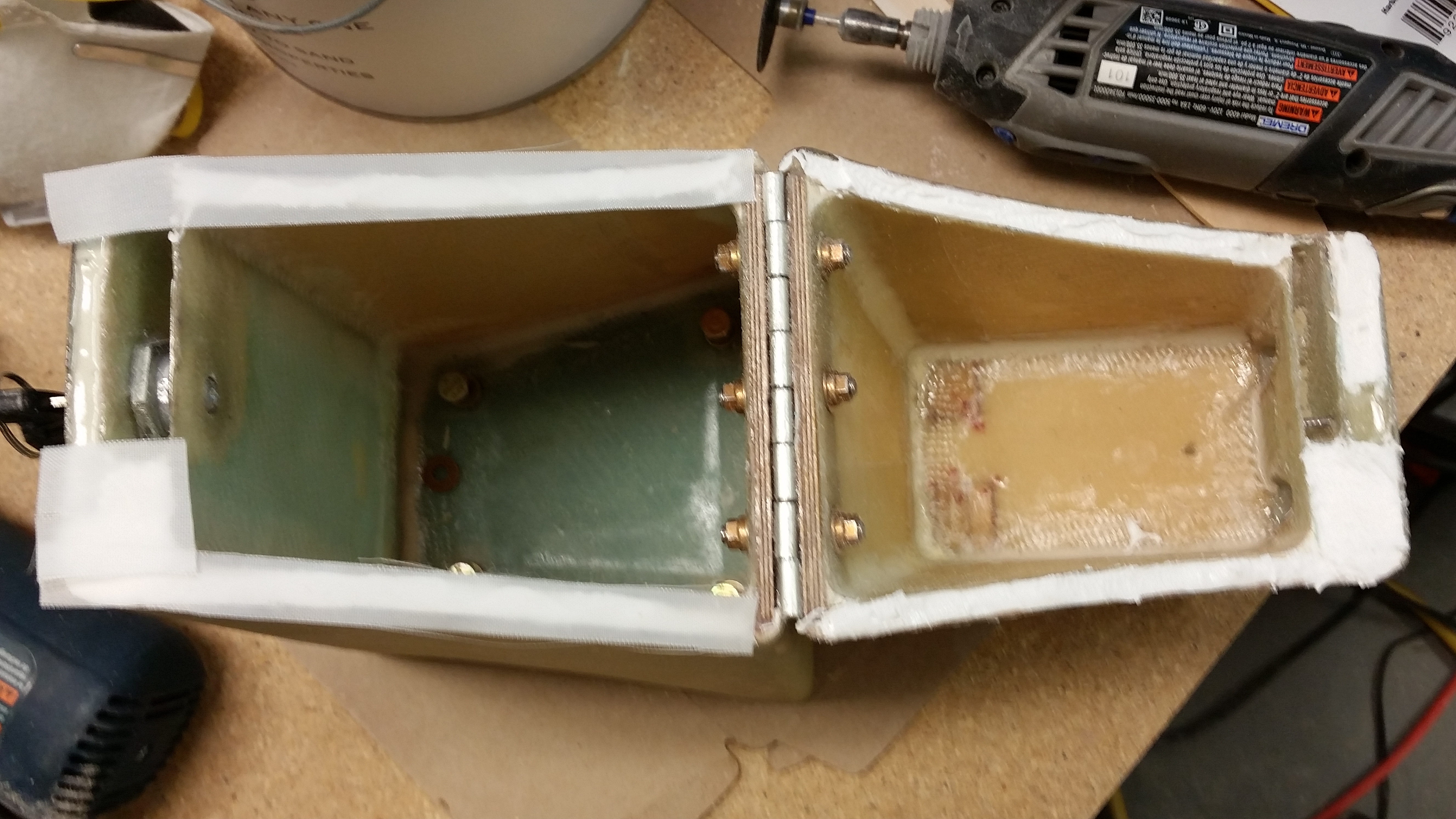
Applying micro to headrest edges

I then peel plied the micro, closed & locked the headrest and then weighed it down to compress the micro as best possible.
Peel plied then weighed down

I’ll most likely cheese grate the second application of micro later this evening, but for the sake of expediency I’m going to go ahead and post this.  I’ll continue to focus on the canard over the next few days, but I will start working on the new elevator cores as well.
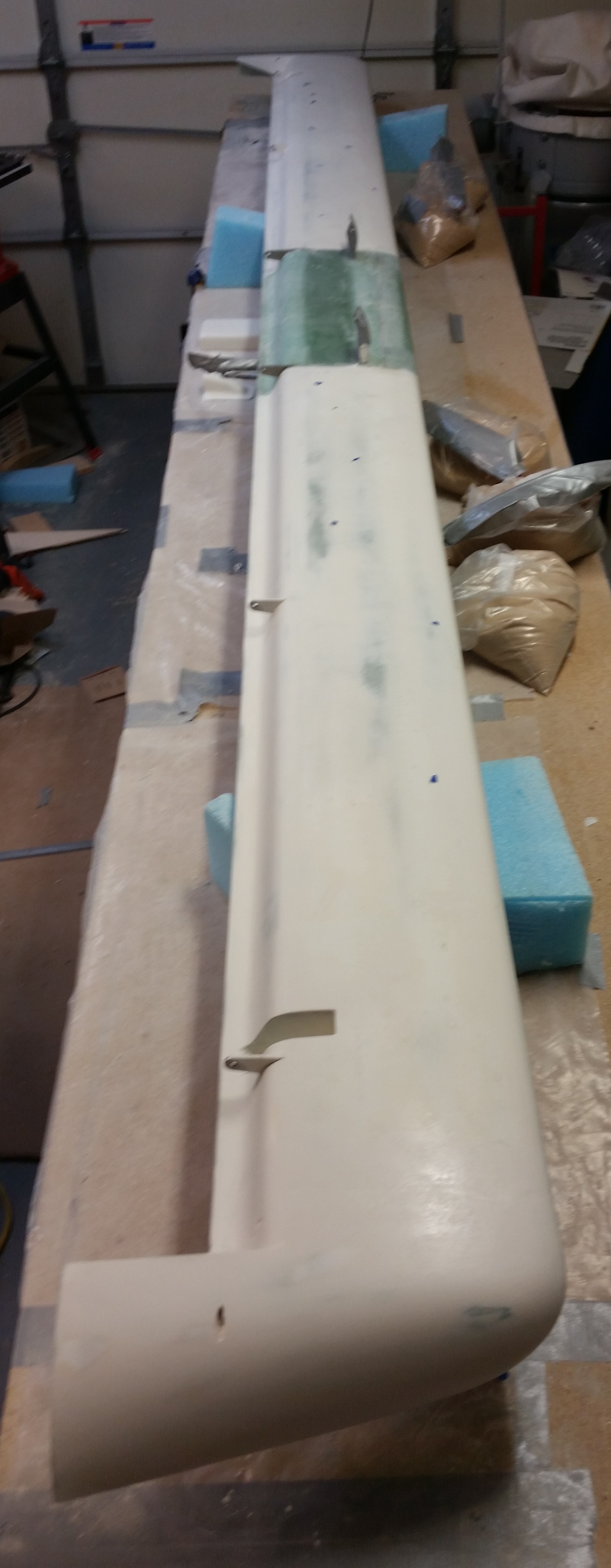
 

Chapter 25 – Making it to the top!

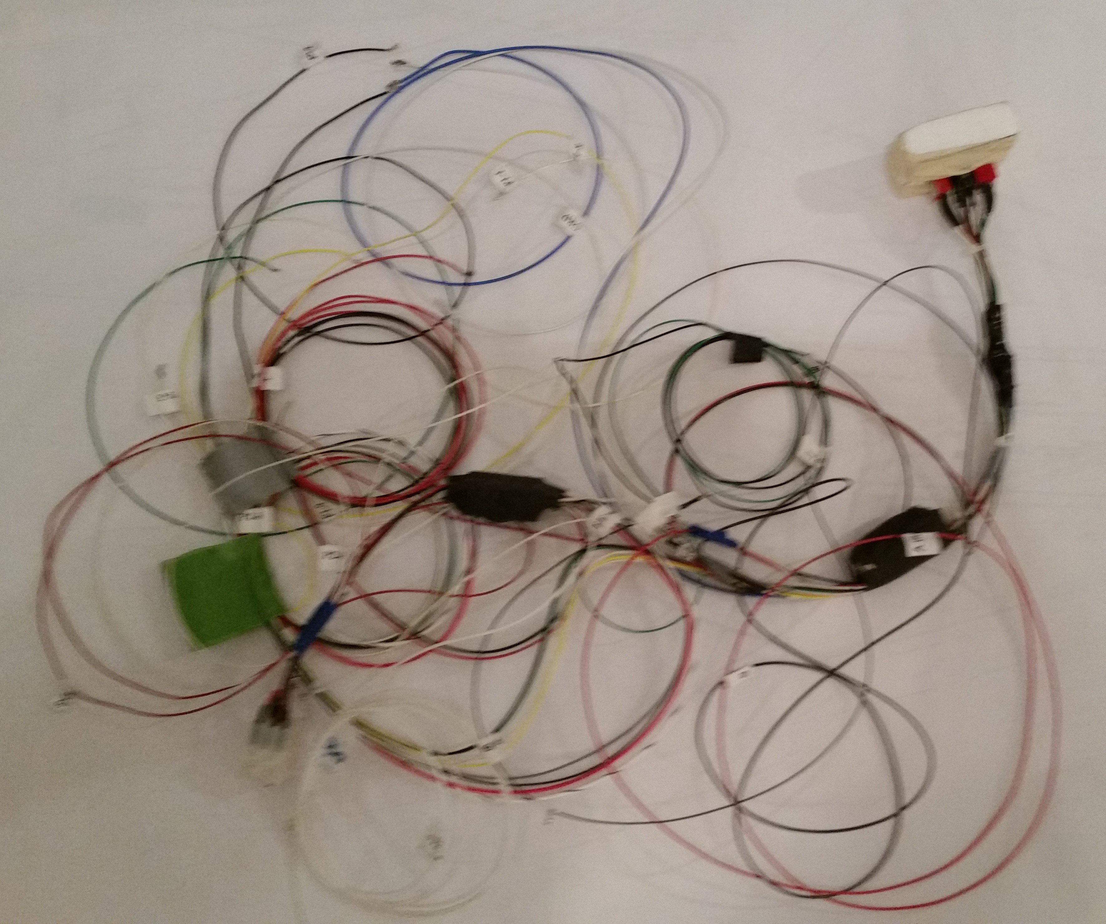
I spent the first half hour this morning finalizing my wire tracking & matching endeavor on the EZ Noselift Actuator wiring harness.  I got down to 2 unclaimed wires, but wasn’t sure & couldn’t tell by the wiring diagram if they were supposed to be spliced together, although I suspected they were.

Crazy wires

I fired off a quick e-mail to Jack Wilhelmson to verify a few things on the wiring and he e-mailed back shortly later to set me on the straight & narrow path!  So all is good thus far in the wiring department for the nose gear actuator.

After I got everything straight with Jack, and as I was waiting for his e-mail, I was finishing up some research on Amp CPC connectors on Mouser.com.  I ended up calling Mouser to confirm that I was ordering the correct stuff.  After cracking the code on the various pins & sockets for the Amp connectors, I fired off my dorder to Mouser for Amp connectors to replace the Molex connectors currently used in the nose lift actuator system.

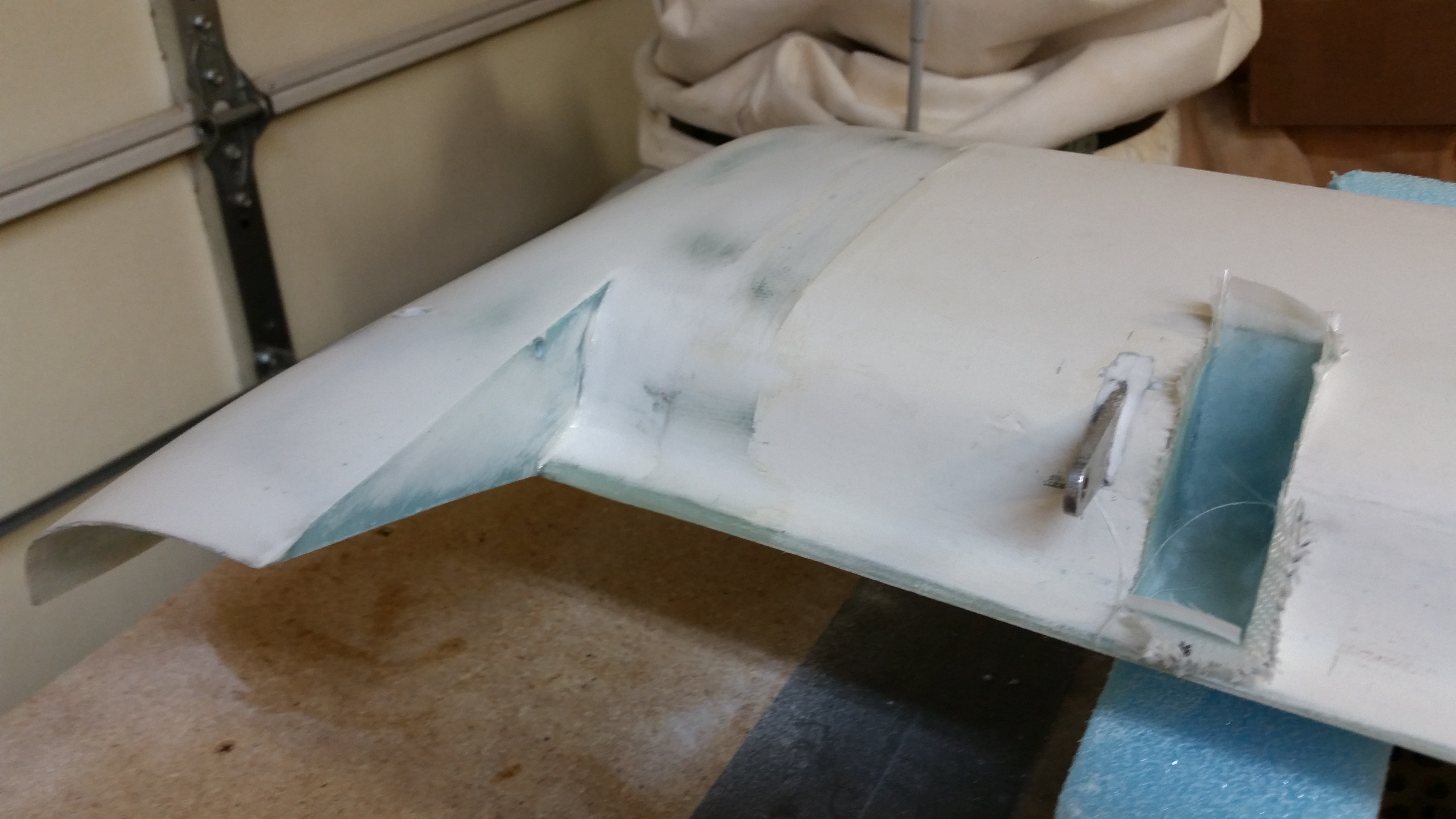
After I got the nose gear actuator system’s electronics straightened out, I started back on my quest to get the canard finished.  I ended up sanding the bottom of the swoosh tips, the area just inboard of the swoosh tips and the 2 outboard elevator hinge pin areas on each side.  Quite amazingly, by the time I was done on the bottom of the canard, 3 hours had flown by.

Sanding last stage of primer

The corners where the canard end caps (swoosh tips) meet the TE take a while to sand and are time-busting PITAs!

Sanding last stage of primer

After I got the newly primed areas sanded on the bottom bottom of the canard, I went to work on mounting the canard right-side up to finish the top of the canard.  To be clear, my buddy Mike recommended I wait so that I can finish the middle nose fairing on the canard at the same time, but I may utilize an alternative center canard fairing which would negate the standard plans canard nose fairing.

In addition, as I’ve mentioned before (and I have thought about this a fair amount while I’m finishing the canard):  As much time as it takes to finish the surfaces of this plane motivates me even more to finish the parts I can in prep for paint so that the finishing of all these parts don’t come due at one time!

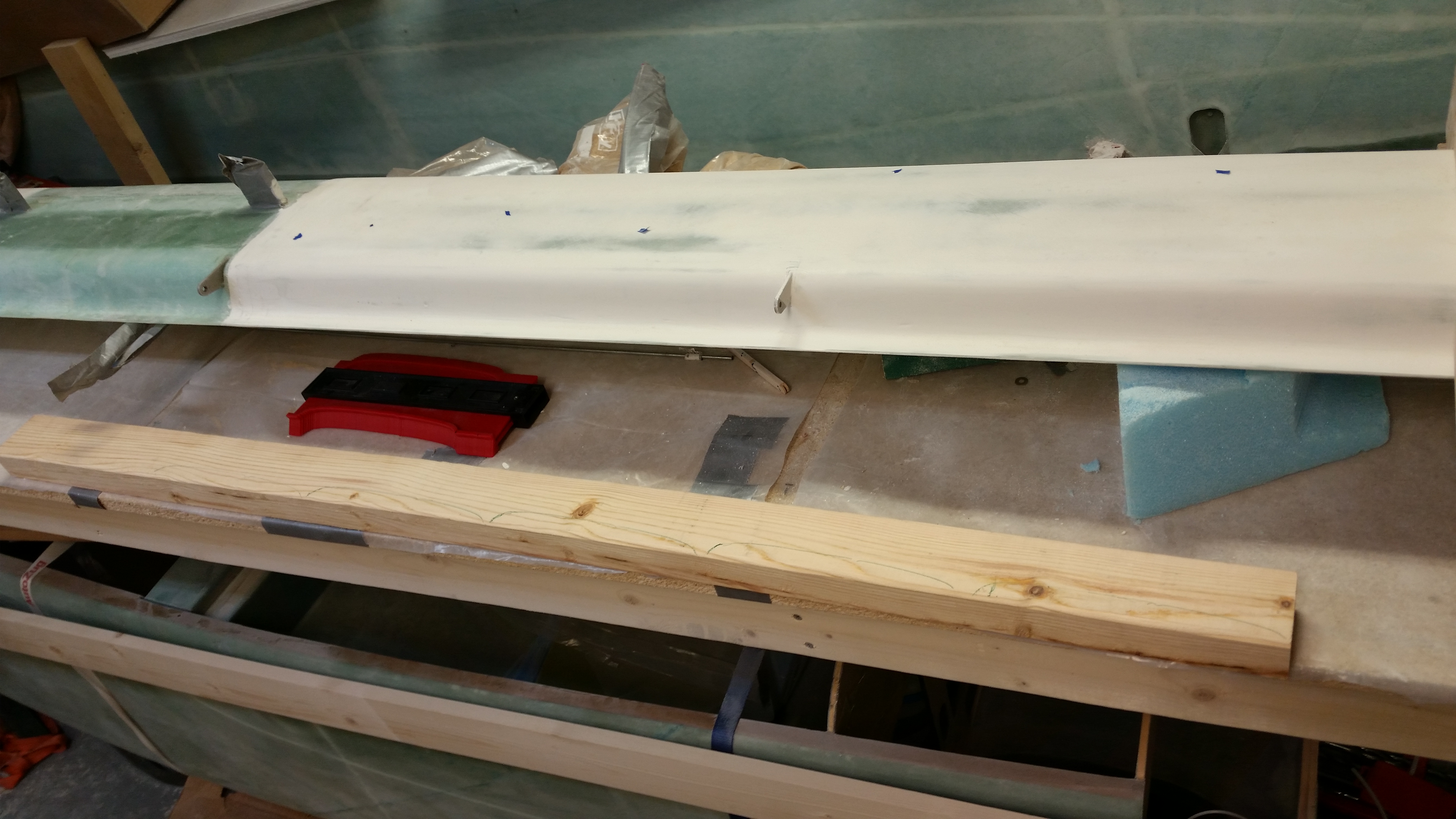
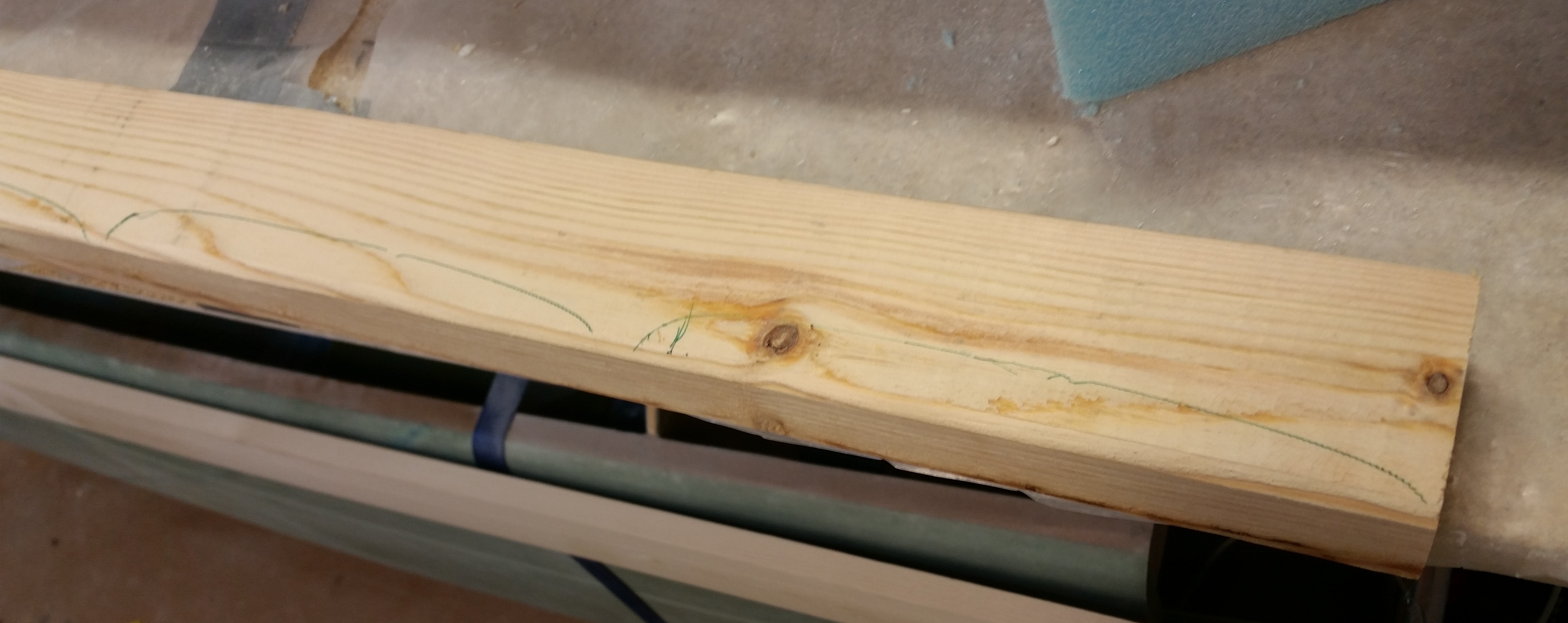
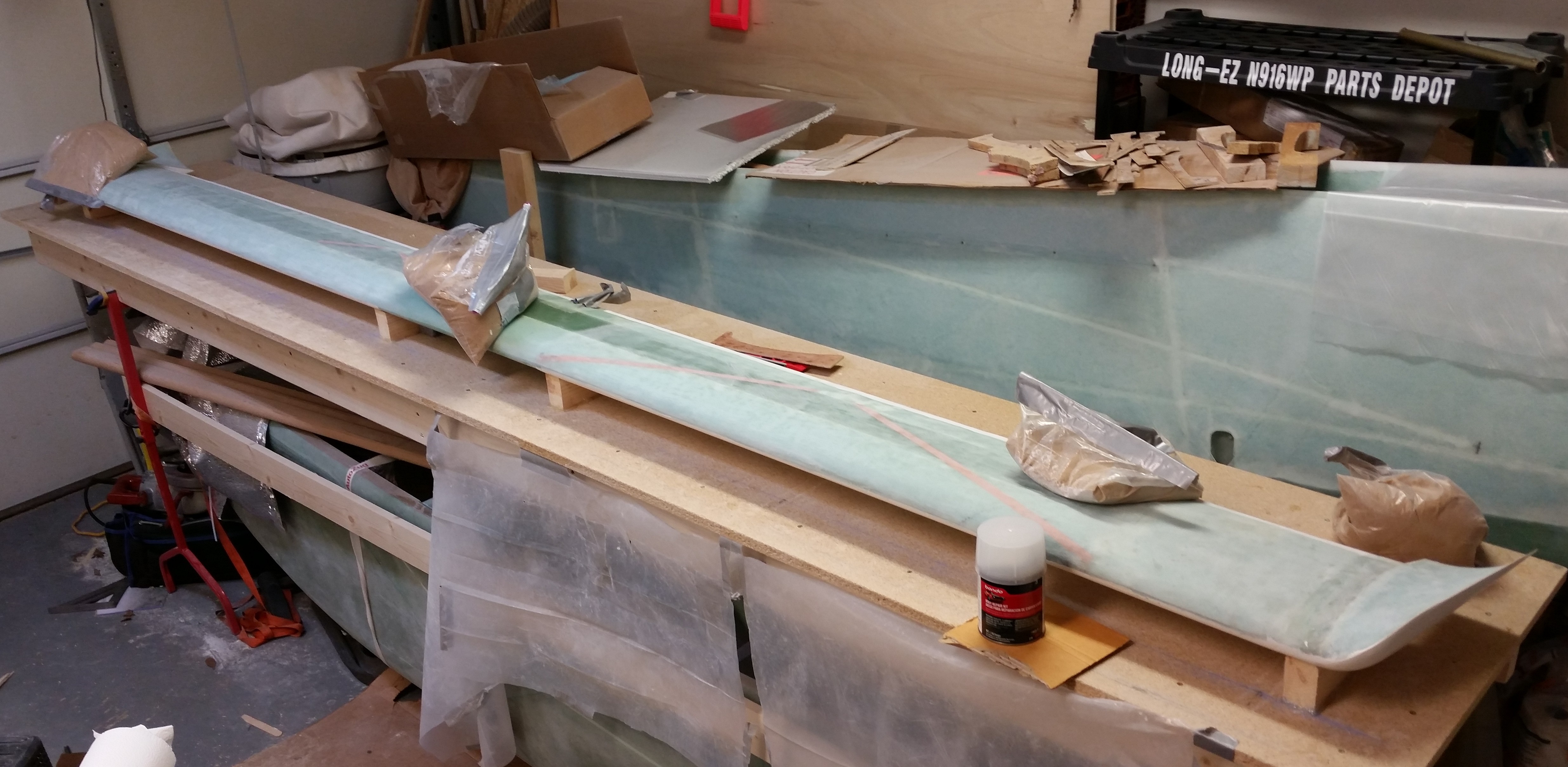
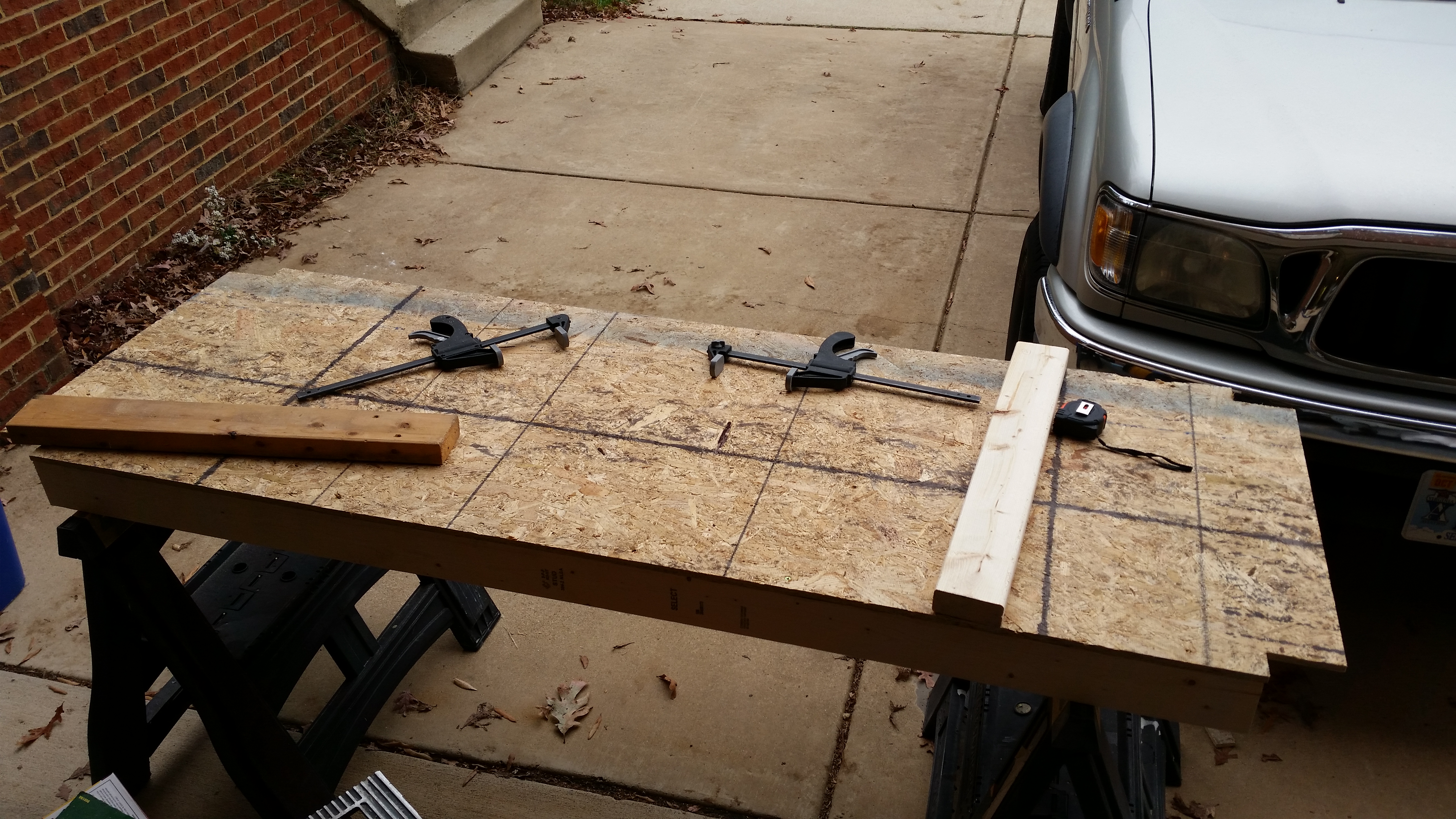
I ended up deciding to use 2×3 blocks under the canard to hold it in place while I finish the top.  I marked the lower curvature profile of the canard in 5 consecutive spots on a 5′ long 2×3.  I used the lower contour profile as a template and after marking the 2×3 I cut out my mounting blocks.

Prepping canard supportsPrepping canard supports

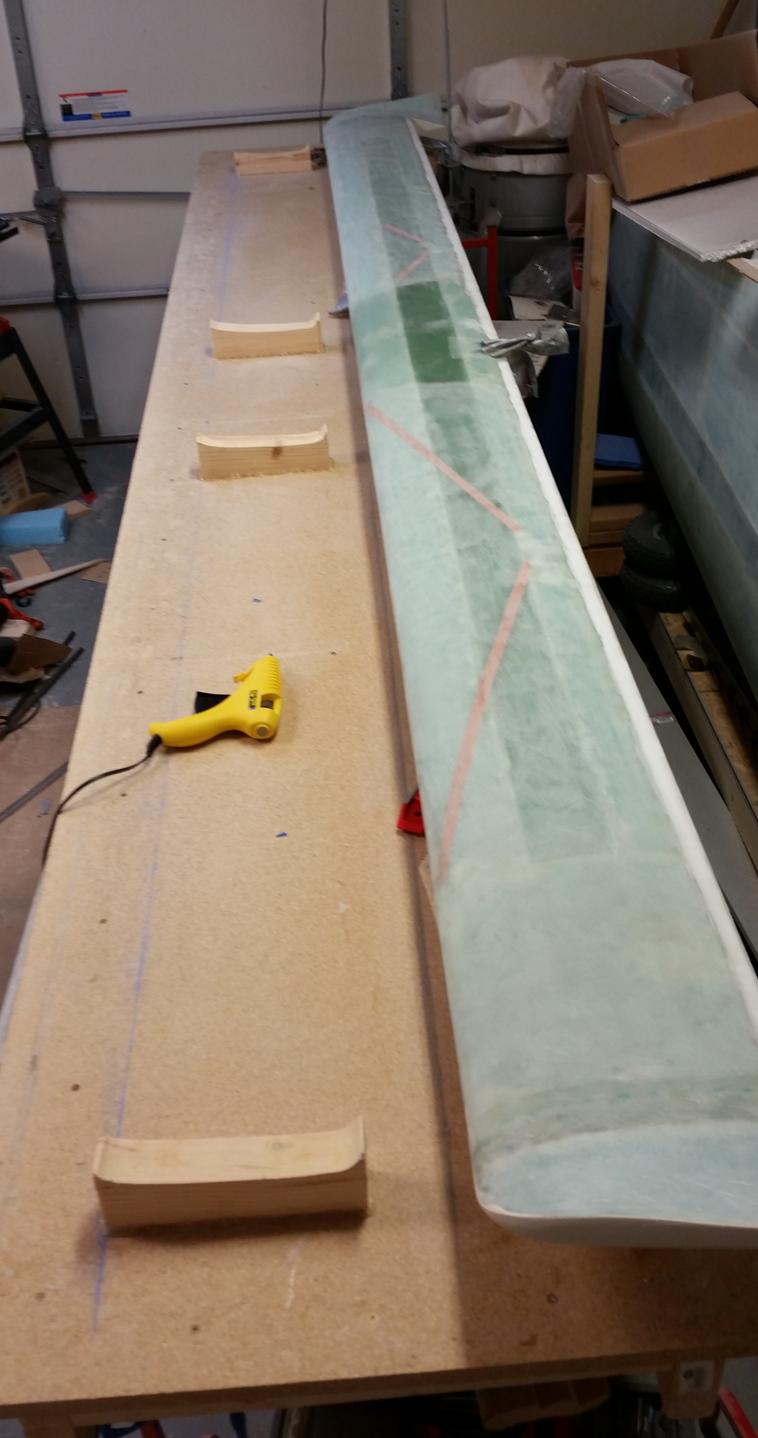
Here are the blocks ready to be hot glued to the work bench.

Setting up to finish top of canard

I ended up only using 4 of the 5 mounting blocks, and I’m mounting them in the middle of the canard, where finish won’t matter, and at the ends where the swoosh tip junctions meet the canard ends, since these areas need some work on the transition anyways.

Hot gluing support blocks in place

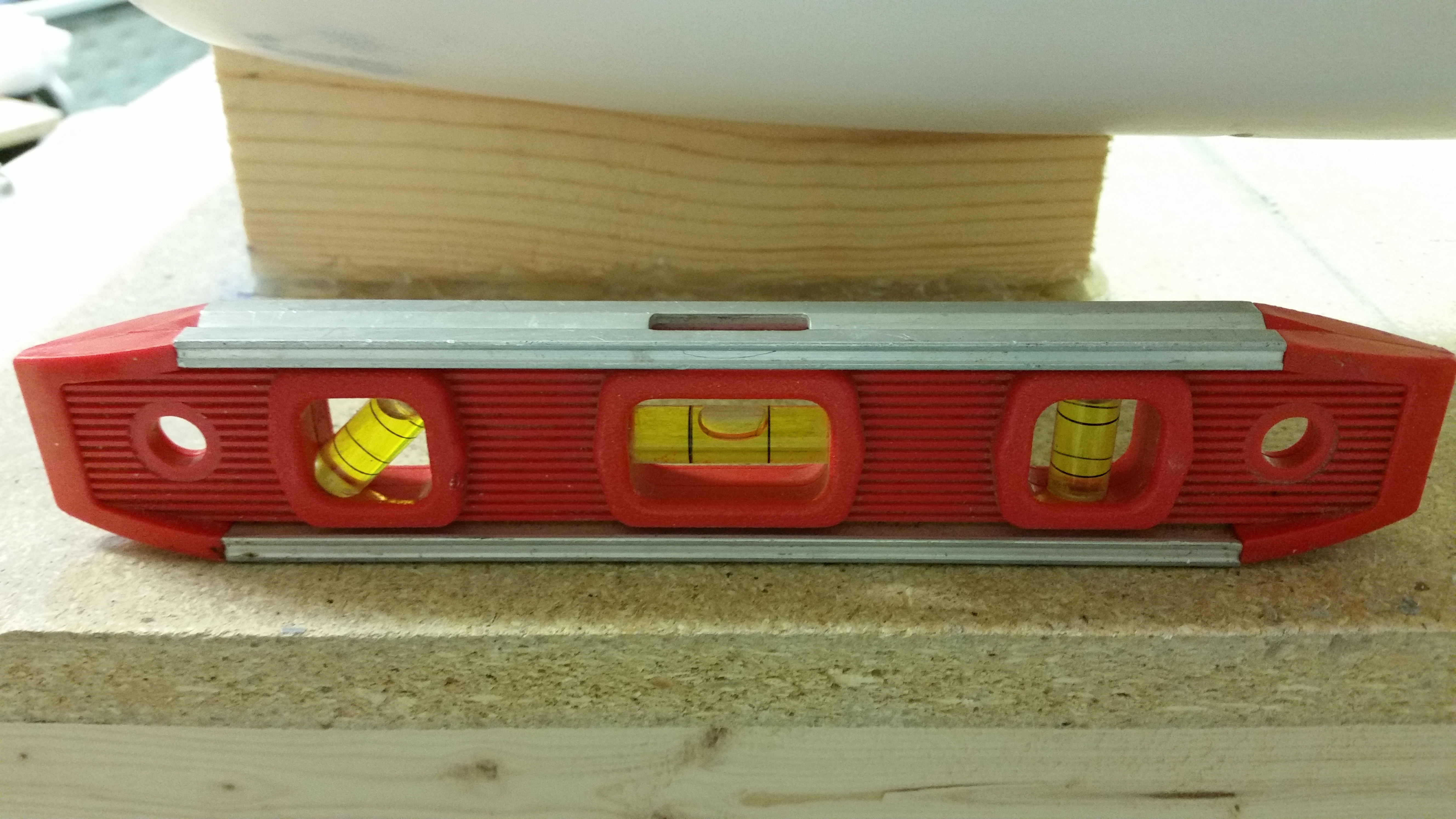
I then measured the angle of the table again on each end.

Checking work bench angle

And then matched the surface angle of the canard to the table at each end so that it is aligned, to ensure I’m sanding true while using the contour sanding block.

Checking canard mount angle

Checking opposite side canard angle

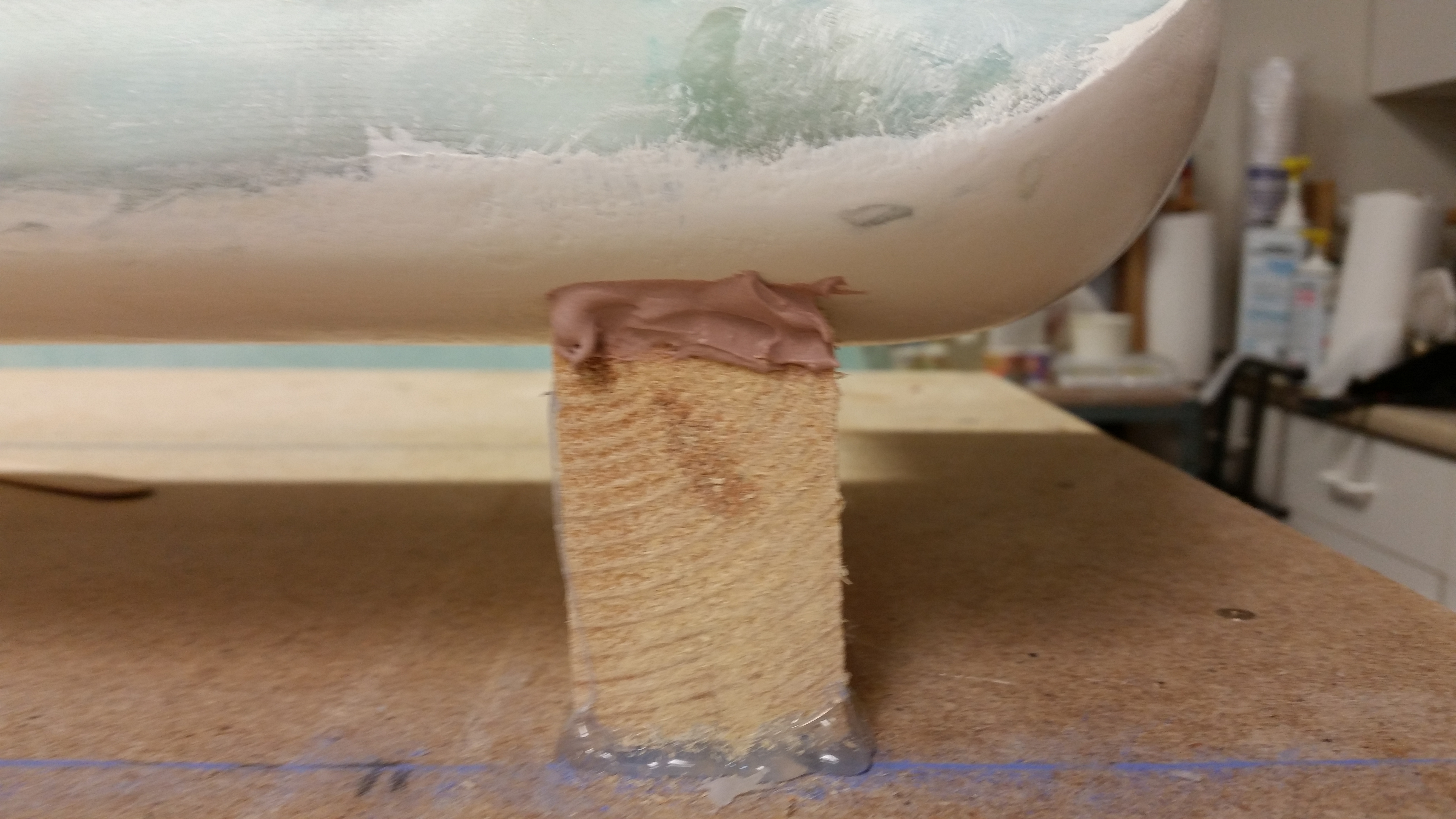
I then broke out the Bondo and set the canard to the 4 mounting blocks.

Bondo'ing canard in place

Here’s a close up shot of the canard Bondo’d to the mounting block.  Note the hot glue holding the block to the work bench.

Bondo'ing canard in place

This is the last time the canard will be in its raw form!

Ready for micro!

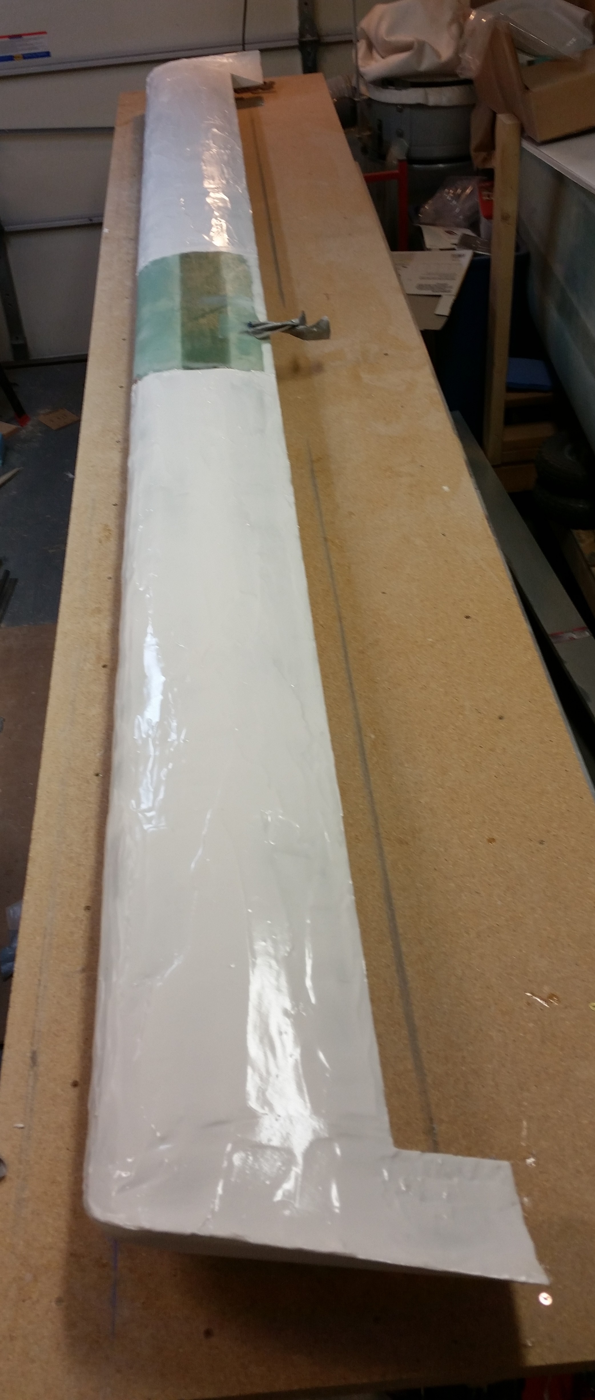
And here’s the top of the canard after I applied the micro finish.

Micro finish applied

After the West epoxy micro cures for 2-3 hours and is in its “green” stage, I’ll cheese grate the surface to knock off all the high points and get the surface cleaned up.


Chapter 25 – Yep, Sanding Canard

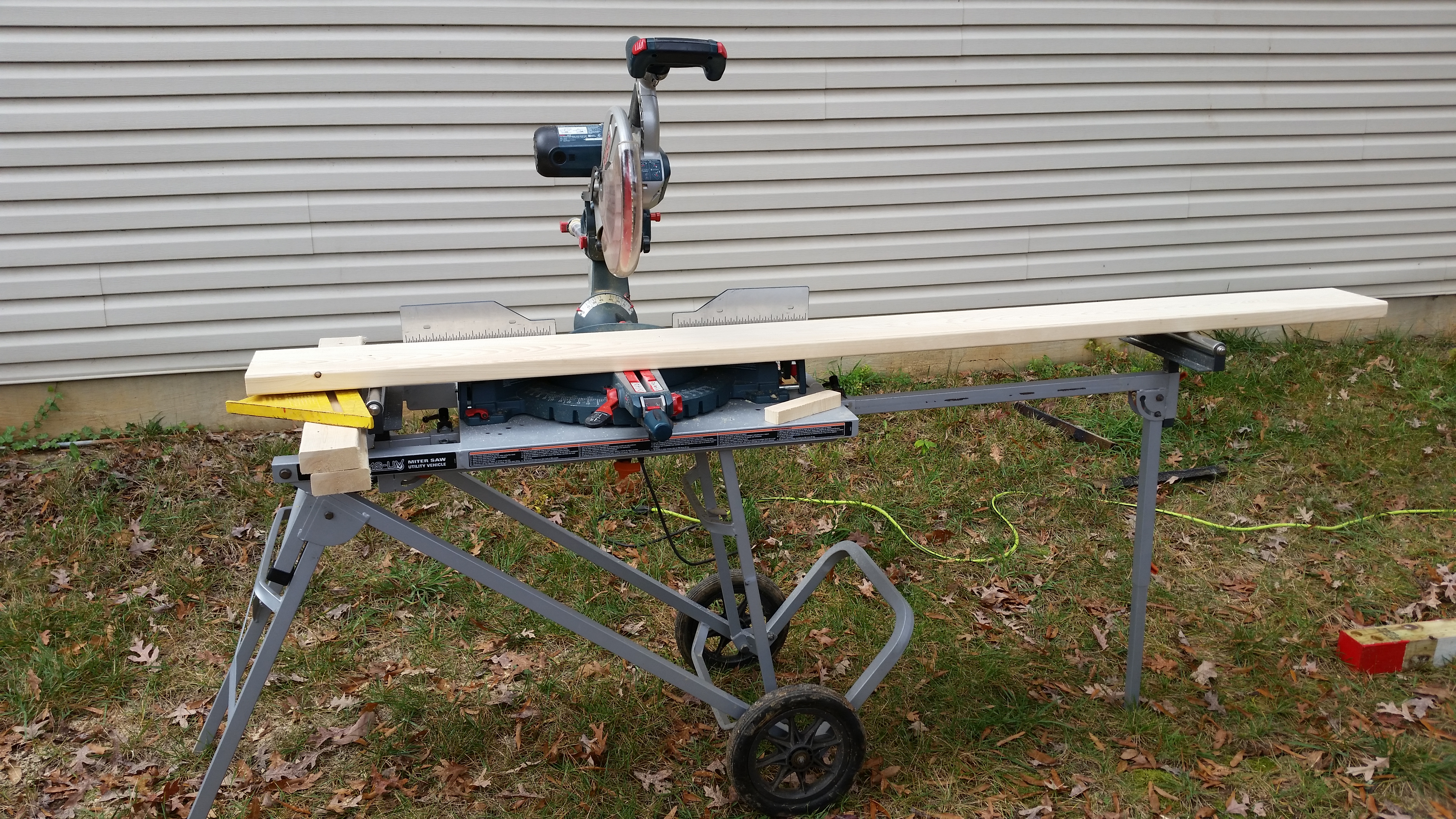
Since there was a good chance of rain earlier today I decided to get the wood for the table platform brackets cut.  In addition, I wanted to get the saw out of the garage and back into the shed behind the house.

Figuring that there wasn’t going to be a lot of visual storytelling going on today, I snapped this picture to show the wood-cutting process.

20151101_115008

My original plan was to get the bottom of the canard sanded and then West micro finish spread on the top of the canard.  However, I ended up spending almost 3 hours sanding down the primer on the swoosh tips, inboard canard tips area, and the two outboard hinge tabs.

Once I fished sanding the first round of primer, I applied a fresh coat of primer on the areas I just sanded.

I then went to dinner and upon returning home I found that the primer in the cup was still flowing out & very wet, so I used it to apply a final coat to build up the total primer thickness as much as possible.

20151101_152803

After cleaning up after the final primer application, I went upstairs & reviewed the wiring diagram for Jack WIlhelmson’s nose gear actuator.


Done Dolly!

I did finish the major build tasks on the fuselage dolly, but allow me to cover the day chronologically:

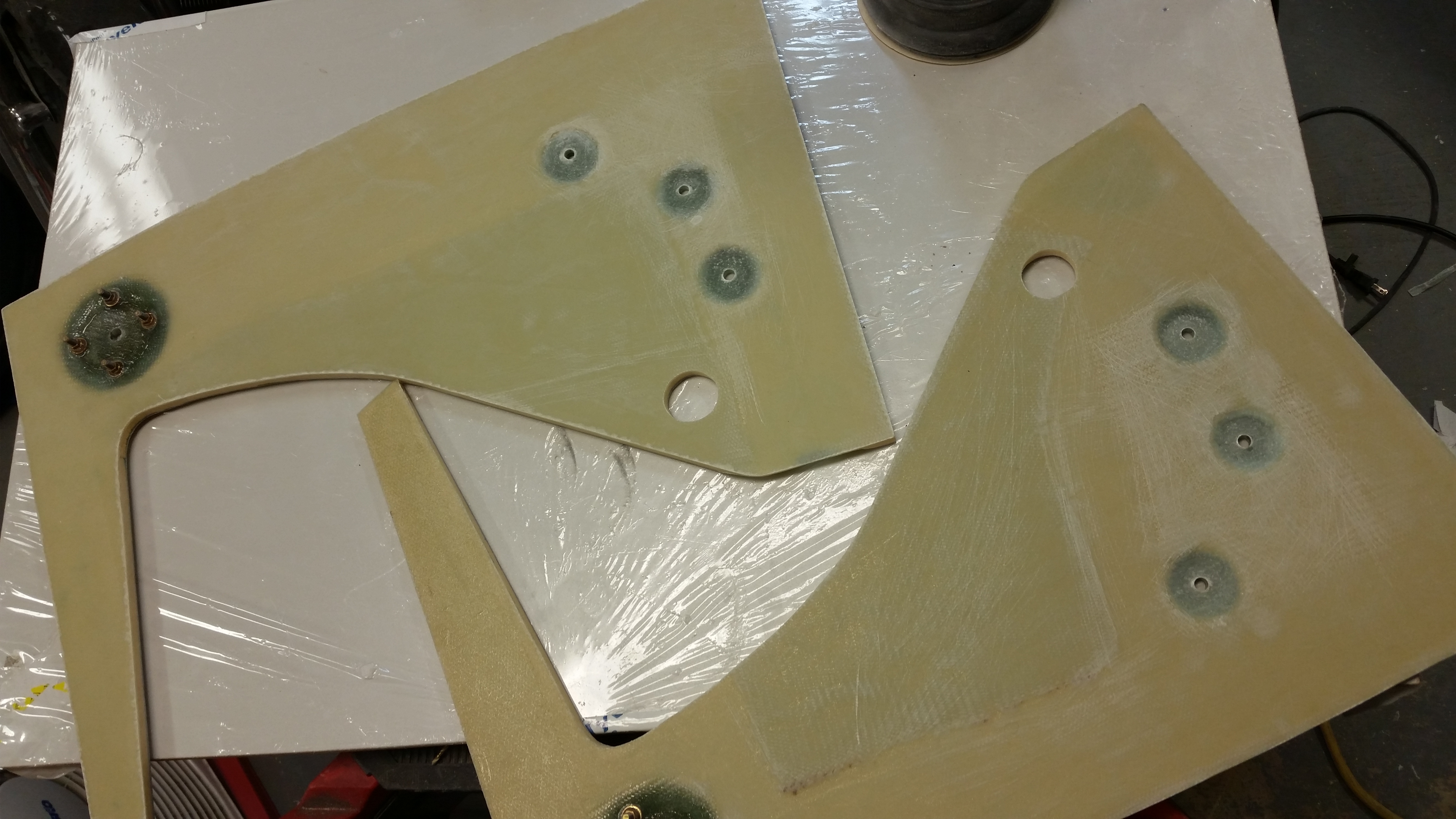
I started off this morning checking the NG30s’ outboard side layups.  I failed to get this pic in the mix last night, but it’s essentially a bunch of heavy stuff that I balanced on separate 2x4s that are resting on plastic over the 3 hard points I just glassed, on each NG30.

Weighing down hard point glass plies

When I pulled everything off, here’s what I found.  Nice & flat!

Aftermath

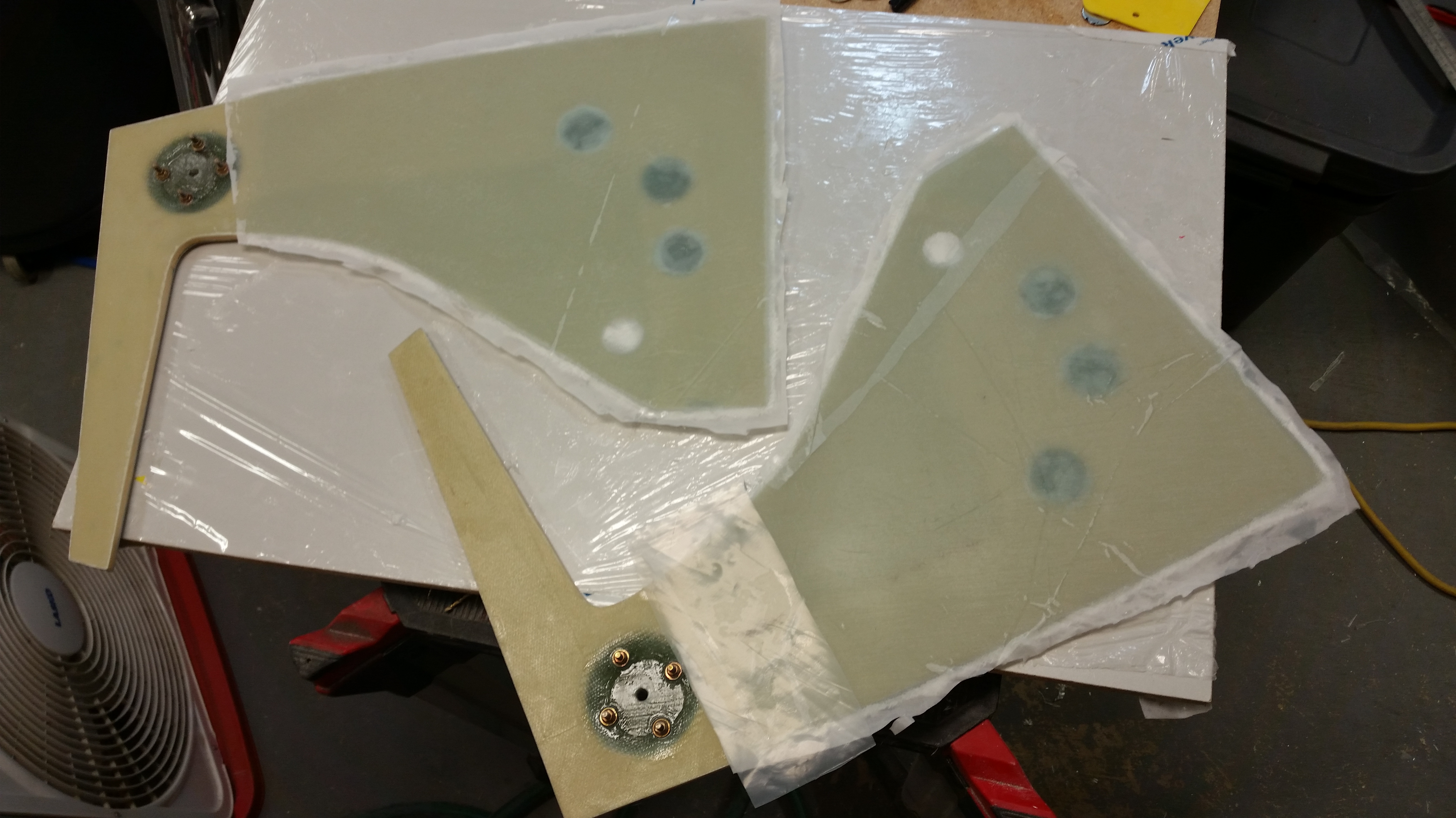
And then I pulled off the peel ply.

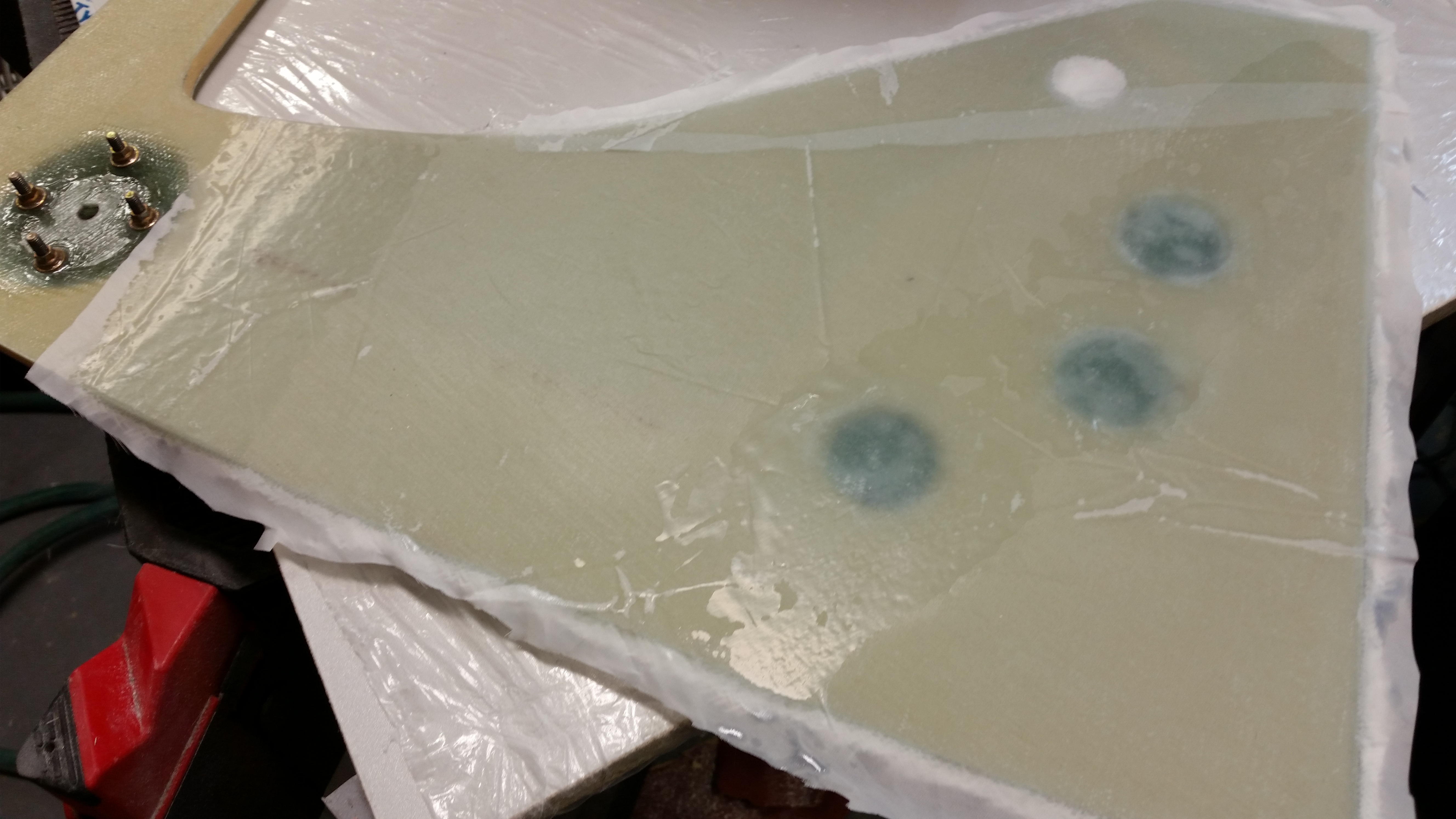
Raw outboard NG30 layups

And here’s the finished product:  Edge-trimmed & sanded NG30s ready for attachment to the F22 bulkhead.

NG30's …. all cleaned up

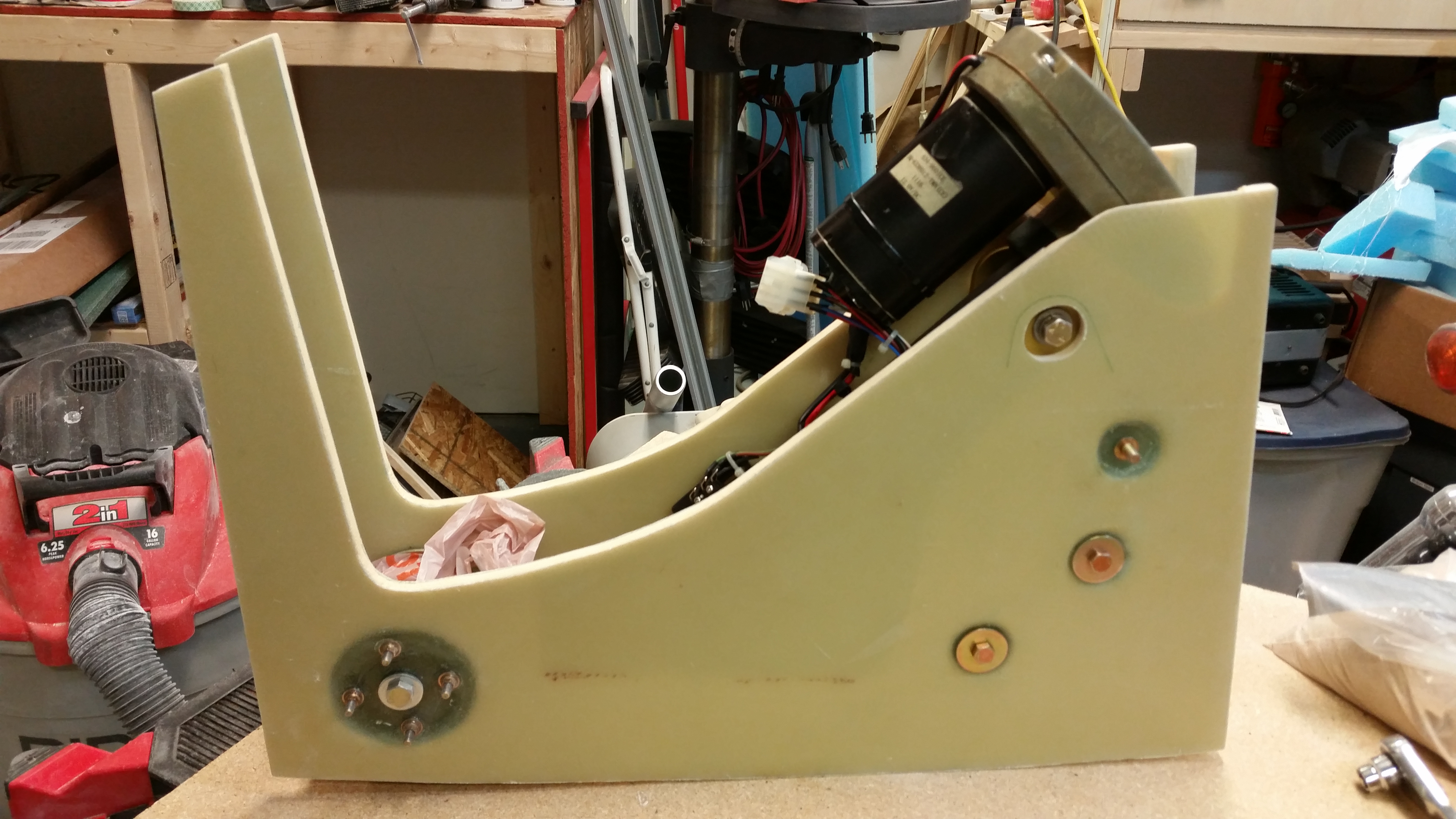
I re-drilled the gear actuator mounting bracket holes and put the NG30 nose assembly all back together to check fit & clearances.  As  you can see, it all looked good and went together smoothly.  I checked the inside measurement of the NG30s and it’s almost exactly  3″, so the width is spot on (it would actually be a little tough to be off with the configuration as it is, with the mounting bracket spacers and all, but still, good to have the right numbers!)

NG30 actuator motor indentsNG30s aft view

Nose gear actuator, nose gear pivot (NG6B) and NG30’s ready for install!

NG30's in install configuration

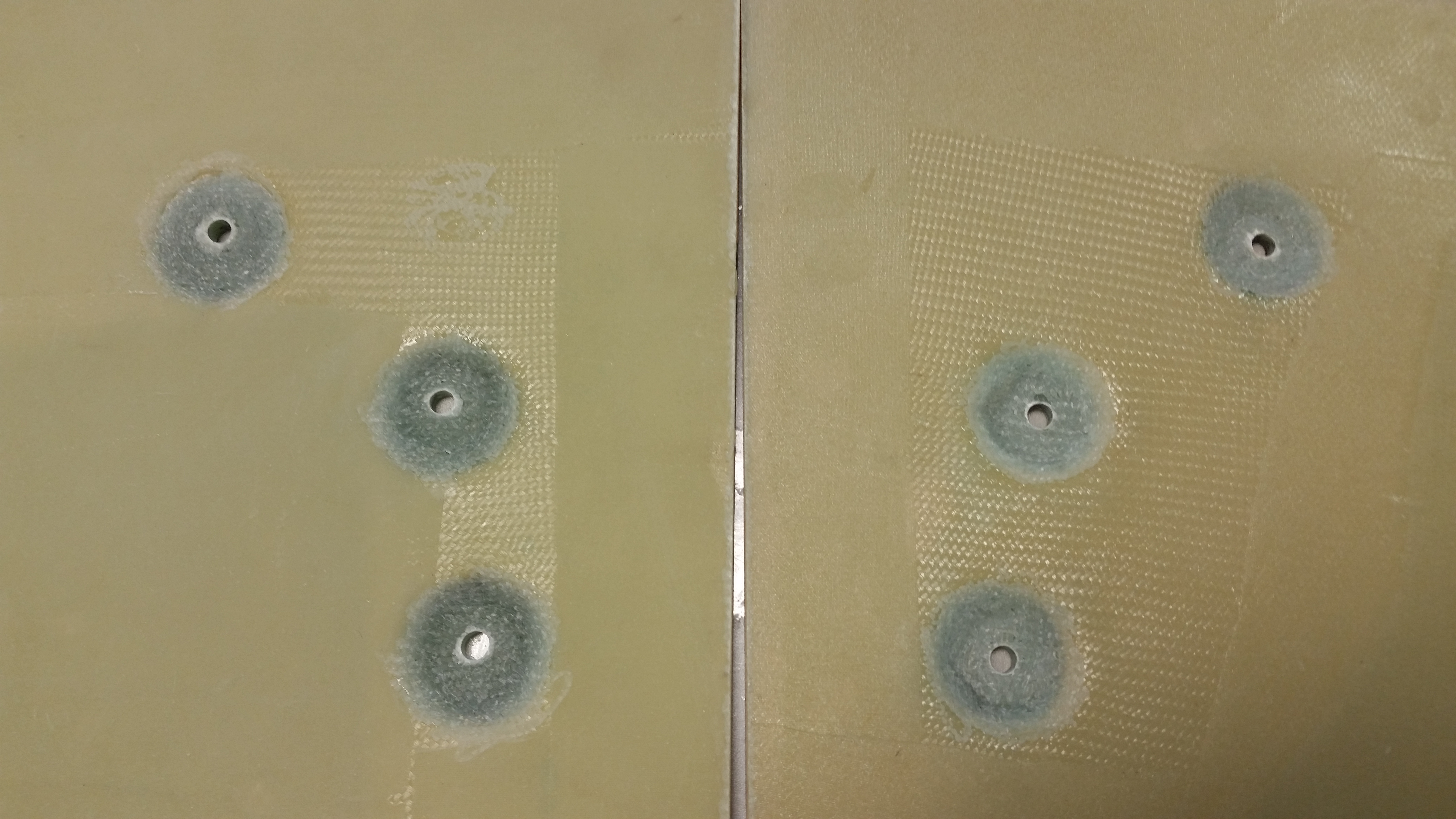
Here’s a good shot of why I filled in the hard point depressions.  As you can see below, the washers sit nice and level on the new glass and there’s no concern over torquing these very important bolts down to the right value.  Nice, clean & EZ!

Finished outboard NG30 layup

After all the work on the NG30s was done for the day, I spent about an hour upstairs researching parts & electrical connectors for the nose gear actuator (I really don’t care for Molex connectors in an airplane so my plan is to swap them out for AMP CPC connectors, as my buddy Dave Berenholtz did).

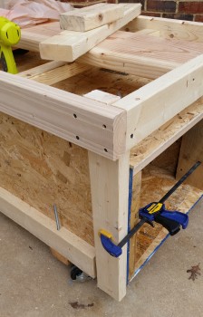
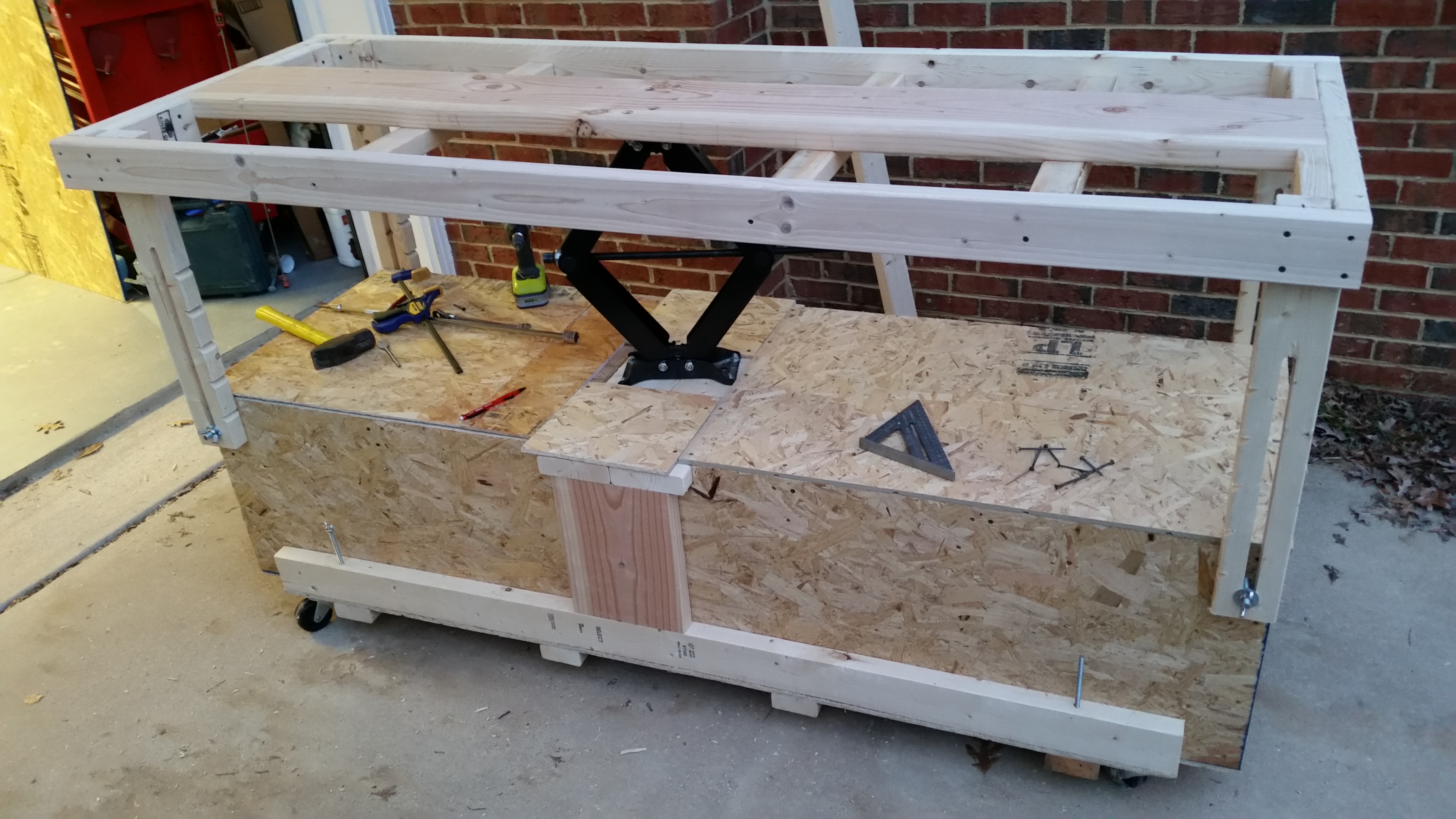
I then opened up the garage and got to work on the fuselage dolly.  My first task of the day was to get all the corner support struts built and attached.  These are essentially the corner table legs that keep the top fuselage table mount steady and secure at each elevation.

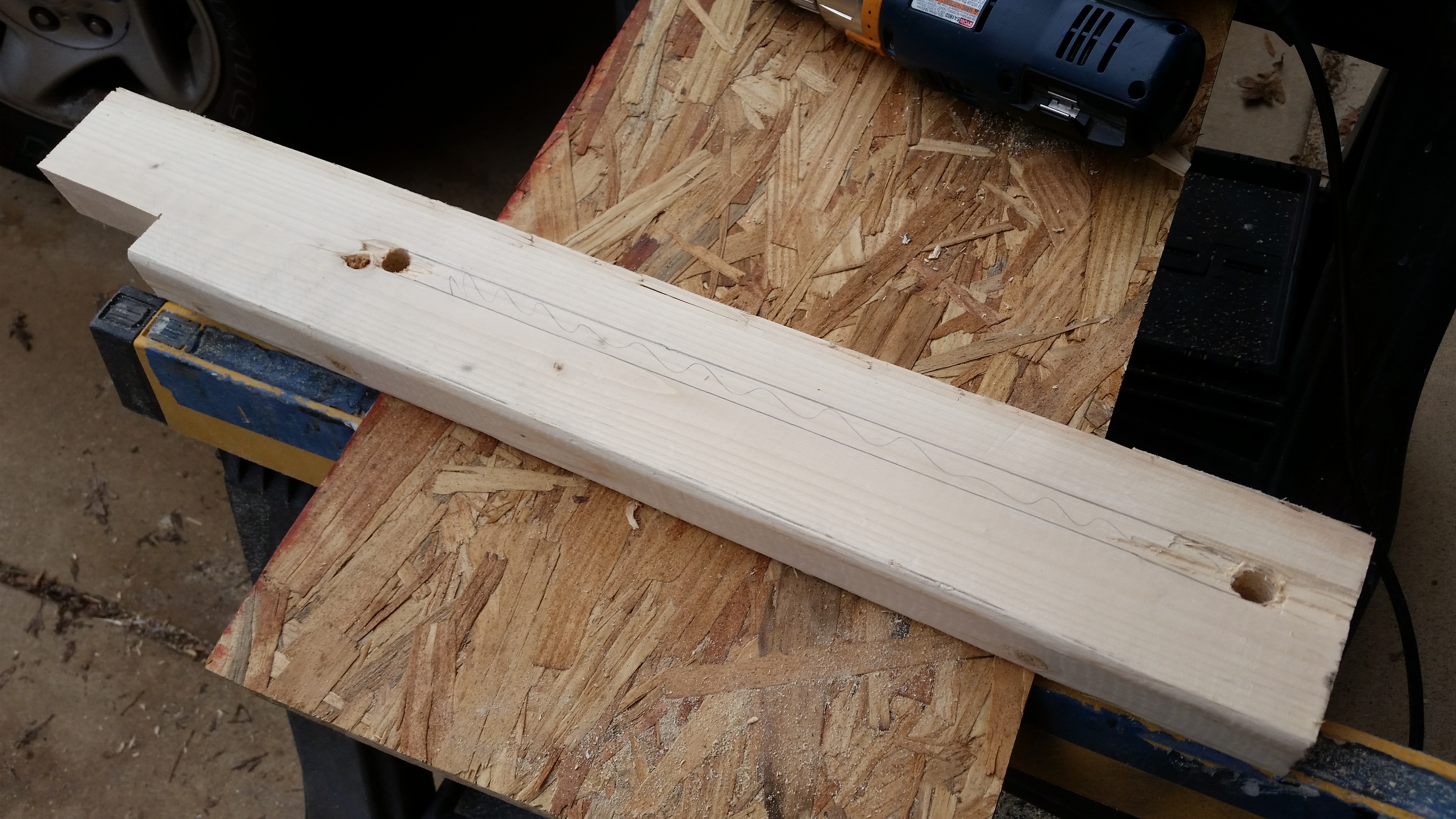
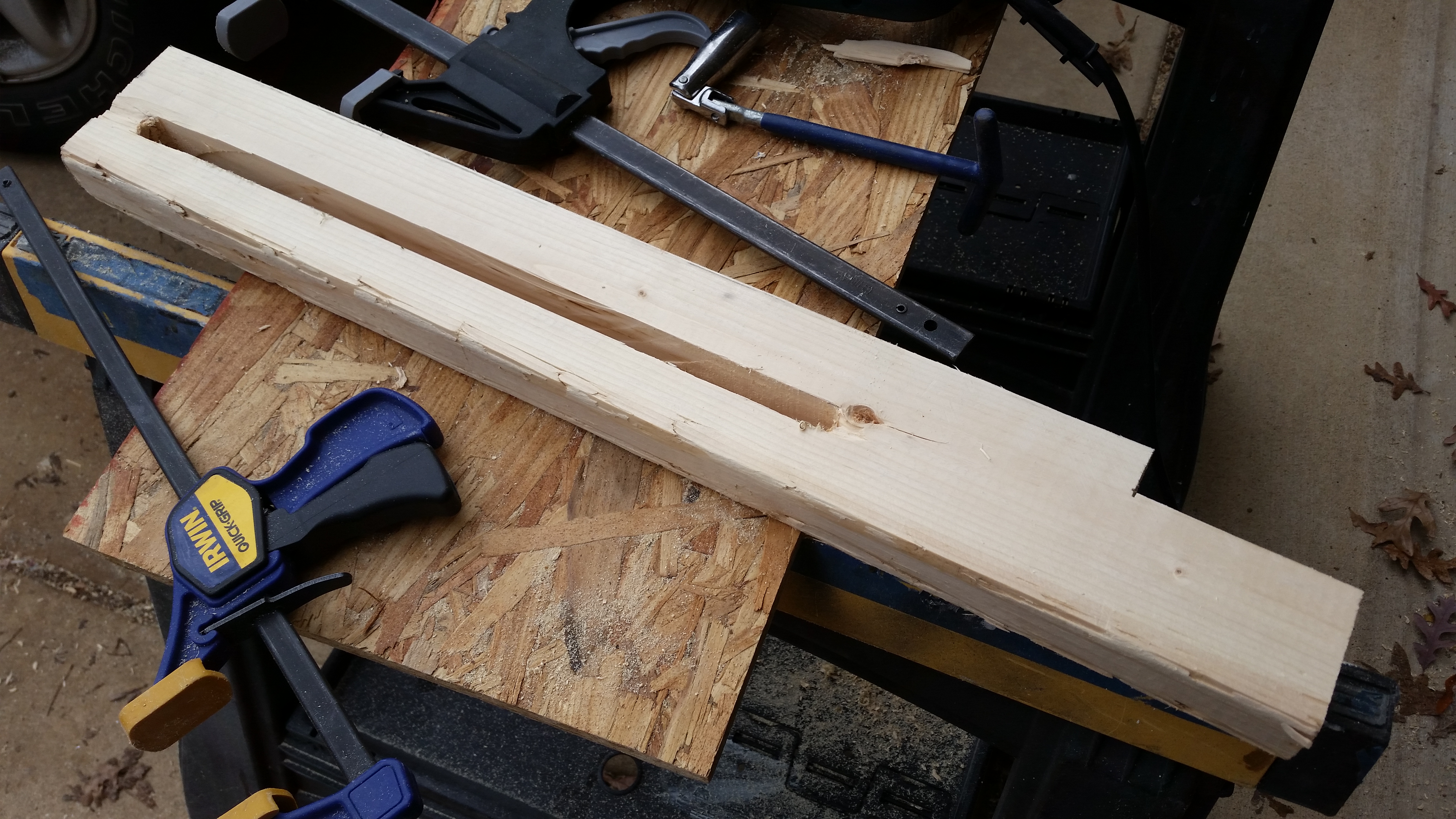
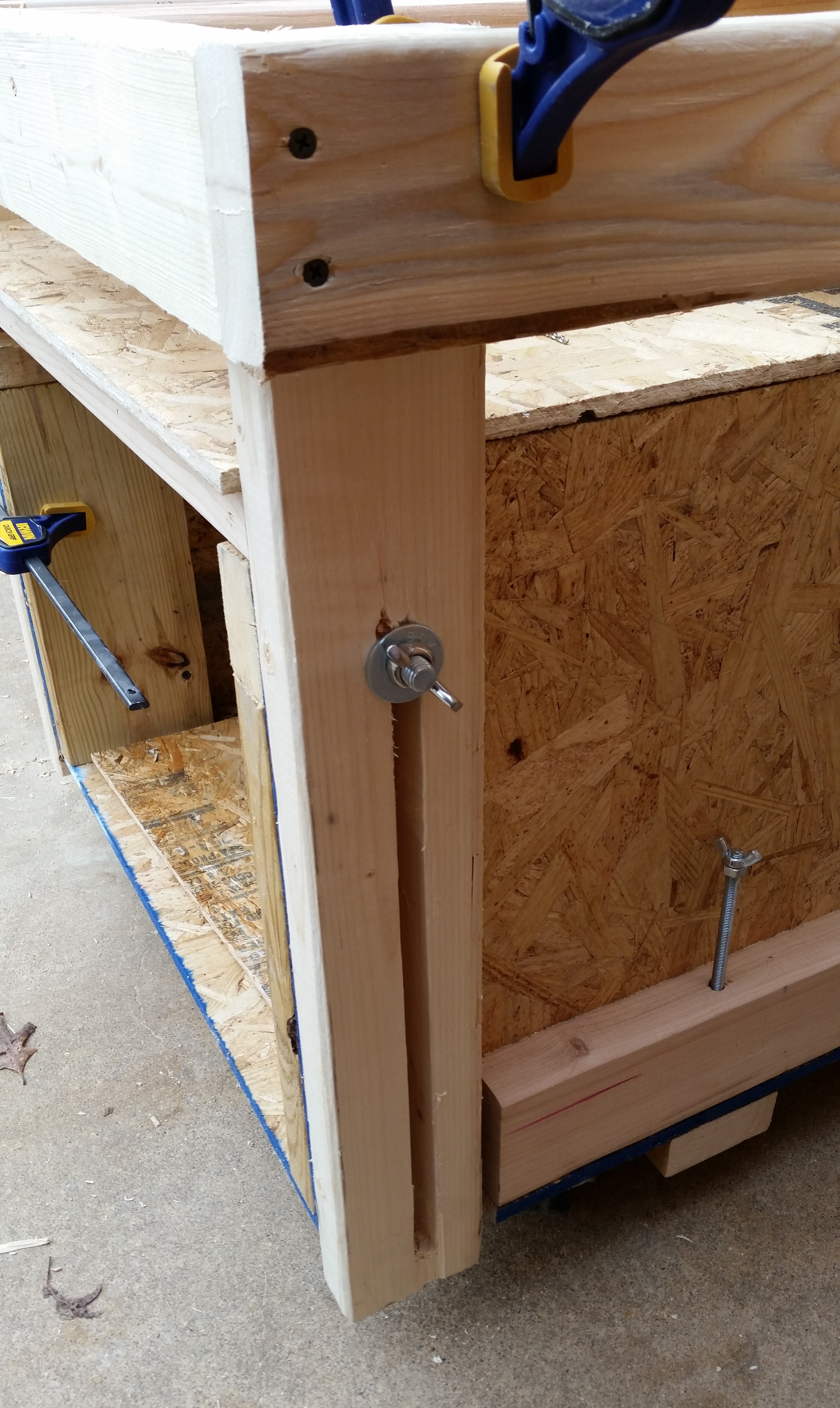
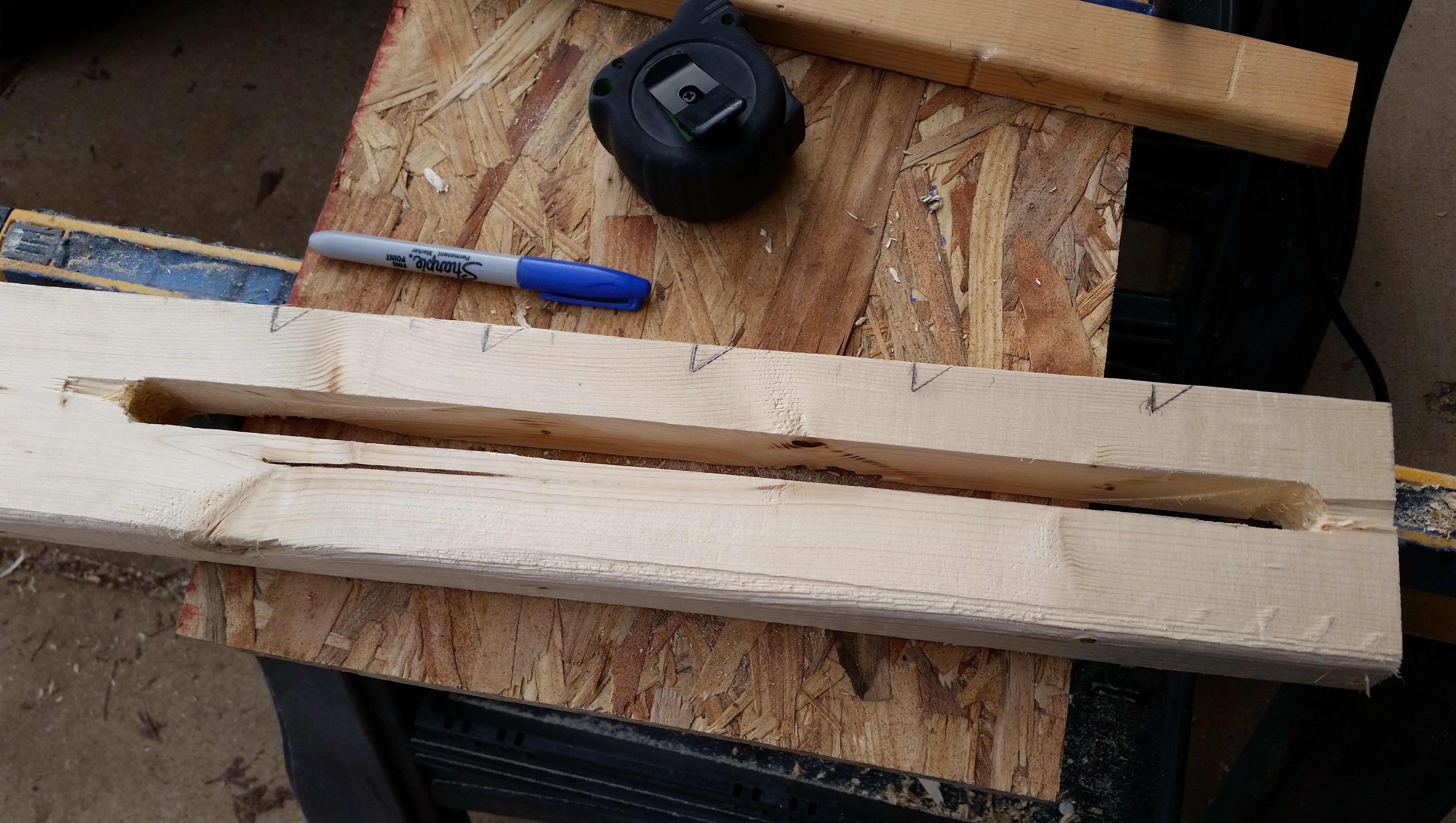
The support struts are simply 2x4s with a 5/8″ slot cut down the center so that a stationary 1/2″ bolt mounted on the lower box slides through the slot.  Then, when the table is at it’s desired elevation, I simply tighten the 1/2″ wing nuts and secure the table mount in position.  A point of note is that I intentionally made the slots in the support struts a little oversized at 5/8″ compared to the stationary 1/2″ carriage bolt (which protrudes through the strut slot) to ensure there was wiggle room in the sliding action to prevent any unwanted binding.

Cutting slot in fuselage dolly support strut

Slot cut in support strut

Here I’ve positioned a corner support strut and am marking the upper point to be drilled out with a 5/8″ auger bit.

Dolly table support strut

Here’s a corner support strut ready to be permanently screwed to the table platform.

Dolly strut clamp bolt

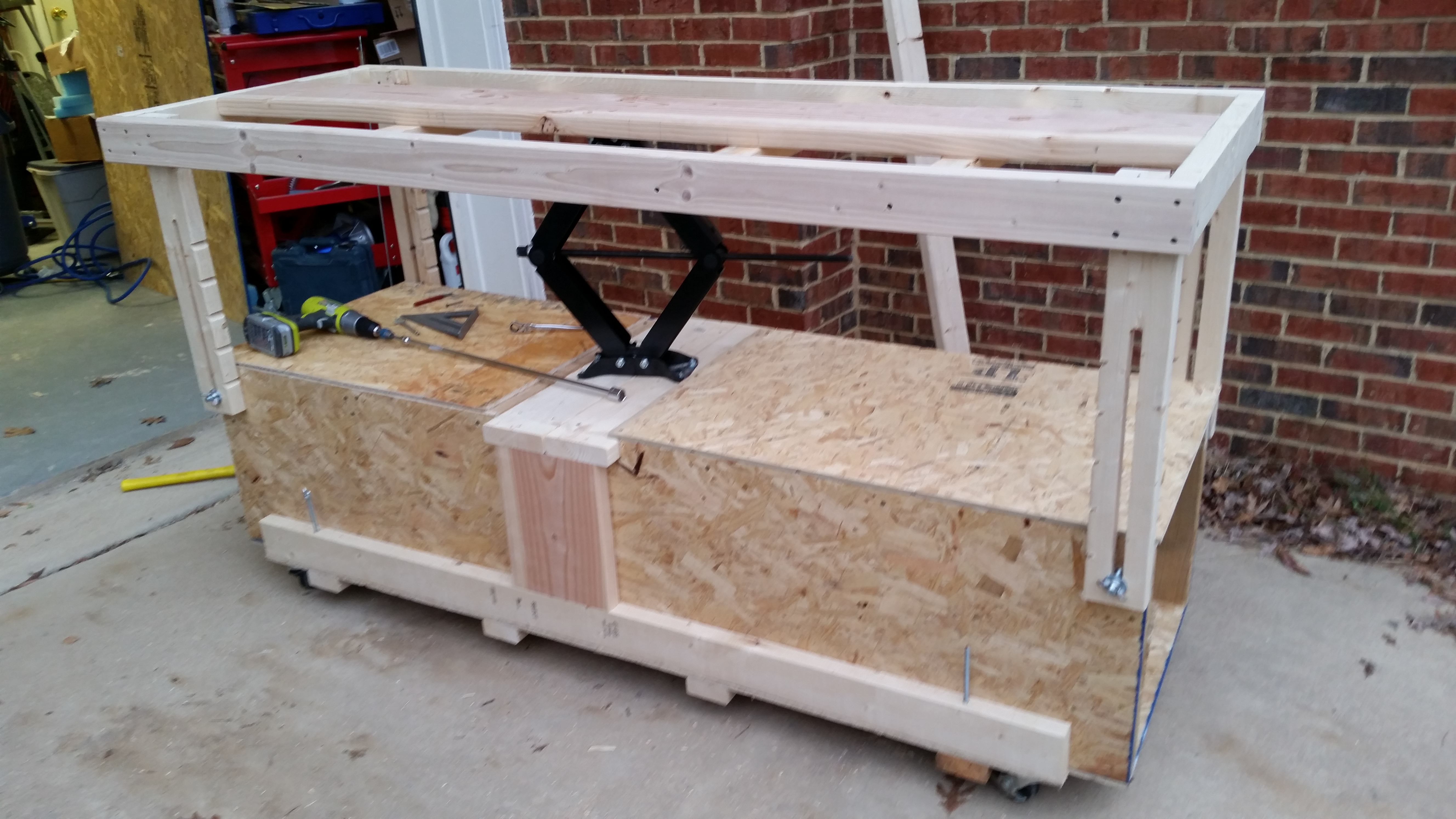
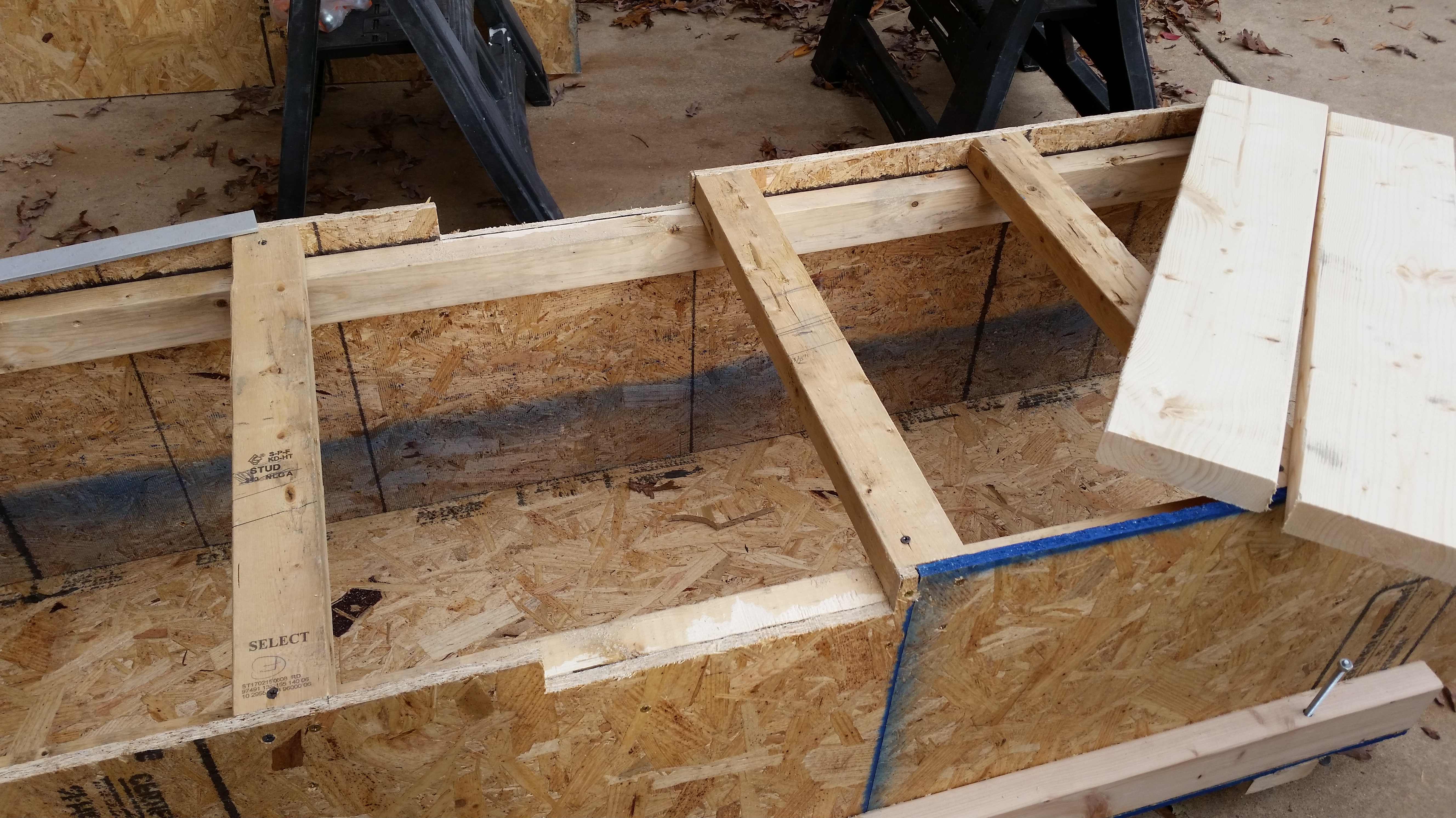
Side view of fuselage dolly with the corner support struts ready to be permanently mounted to the table platform (top work/mounting surface).

Fuselage dolly struts completed

I had also done a bit of research on creating ratchet arms as a safety mechanism since I’ll have a fair bit of weight on this table.  The scissor jack can easily support & lift 5,000 lbs, but the area that it supports is less than 1 sq. ft., so these corner struts are vitally important to the stability of the load on the top table platform.

So although I haven’t designed or made the exact ratchet pawls, I went ahead and notched each corner support strut every 3″ starting from the bottom of the strut for the ratchet pawl to engage with once I make & mount them.

"Ratchet" notch marks

An updated pic with ratchet notches on the support struts:

Table down support struts finished

This is a pic I took immediately after testing out the raising and lowering of the table platform.  So far my plan is working as designed!

Testing table elevation & stability

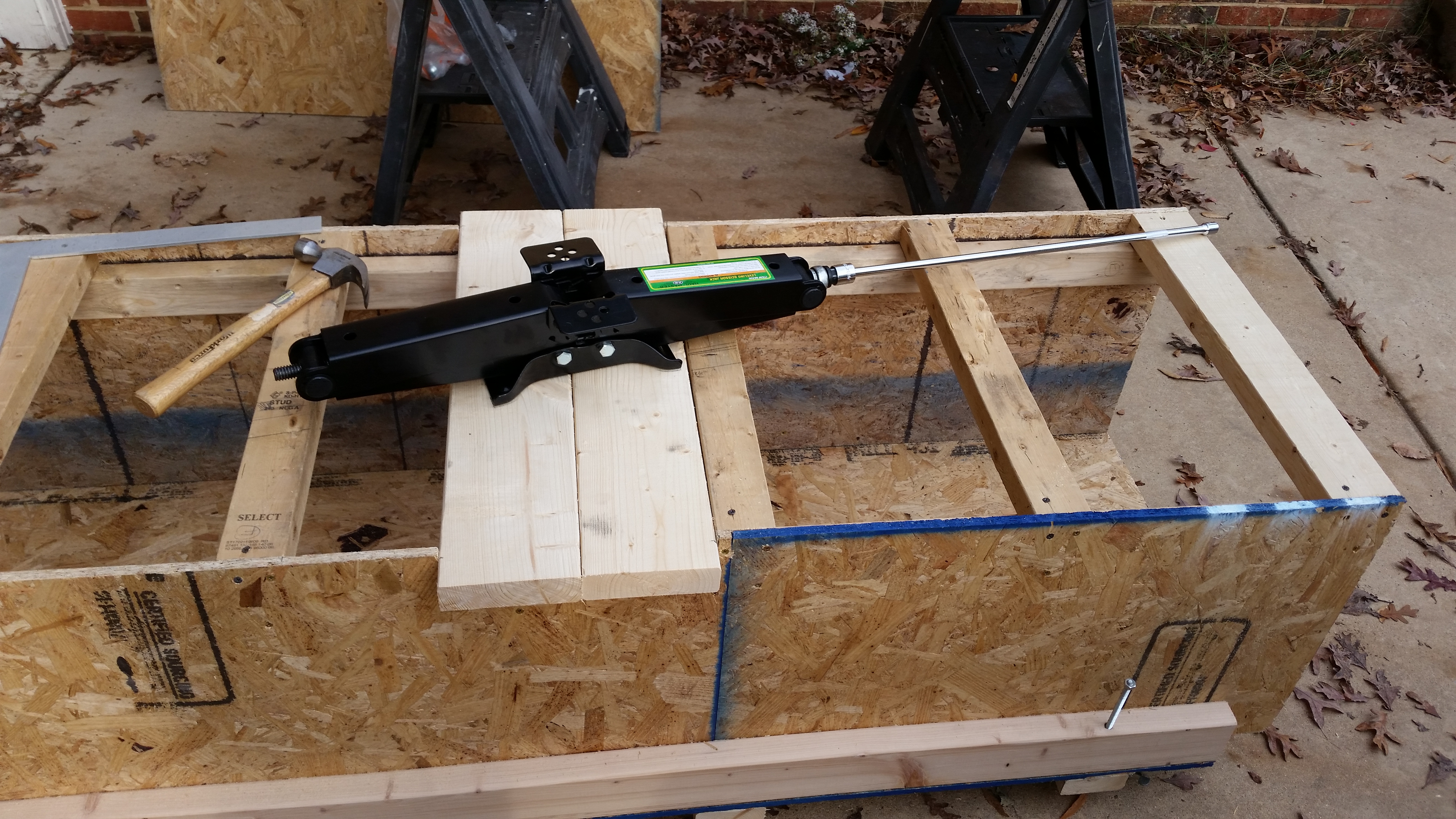
This is pretty much the same view as above, but some minor additions have been made such as cross supports at the end of the table platform and the final install of the lower decking immediately adjacent to the scissor jack on each side.

You may notice in the pics that the scissor jack is not at its full extension height.  This means the height of the table platform is being limited by the length of the slot in the support struts, not by the scissor jack.  I have already planned out additional steps I can implement to allow the scissor jack, and thus the table platform, to reach its max height… IF I really need it to go that high.  We’ll see if I need to go that route during future build tasks.

Almost ready for table top install

It is getting dark much faster these days, and that will be even more accelerated here on the east coast as tonight we change our clocks for daylight savings time.  Thus, by the time I had the top mounted it was fairly dark, so I lit it as best as I could.  After turning on the outdoor lights there seemed to be enough that instead of just taking a simple picture, I figured I would attempt to make a video to show the fuselage dolly in operation.

Now, I didn’t narrate the video because I did this on a whim, and I had music playing fairly loudly in the garage.  However, the mike on my phone hardly picked up the actual volume of the music, so the video seems like a silent film to a degree.  Yes folks! I’m that lazy that it pains me to now talk during my videos!  Ha!

Oh, one other note on the video.  In the video I appear to be hunting & pecking around for the hex drive on the scissor jack that is situated towards the center of the table under the table platform (If I haven’t mentioned it before, I angled it towards the corner for easier raising/lowering operations when the fuselage is mounted on the table platform).  My point is that it’s actually very easy to see and engage the scissor jack under the platform, it was just more difficult & time consuming to attempt it while trying to film the process with a phone in my hand.

Ok, a very final note on this video: the canopy is inside the lower box with the end caps screwed in place, making this a very secure housing for the canopy until I get to Chap 18.


Chapters 13, 25 – I wanna Rock ‘n Roll!

I started off today intent on getting back to the canard, so I sanded the canard swoosh tips, the inboard area of the swoosh tips, and the immediate area around each of the outer two hinge tabs with 220 grit paper for about an hour.

I then got pulled away by a few mandatory errands, phone calls and work teleconference.

I got back to working on the plane at about 4pm, and since the days are getting shorter, and cooler, I figured I would get to working on the fuselage dolly during the daylight, and while it was a bit warmer (vs night), and not raining.  I apologize but since I left my camera upstairs and I was in the “I’ll get it in 5 minutes” mode, alas, there are no pics.  However, what I did was basically cut the remaining canopy box covers & the framed the main table top and mounted it to the scissor jack.  There’s a few more things I need to tweak to optimize its operational use, but I can already tell I’m going to be really happy with the functionality of this fuselage dolly.

I ended up spending about 3 hours on the fuselage dolly.  My guesstimate is that I have just about another 2 hours to go to finish it up.

After the 3 hours were up (and it being too dark to see any lines on my tape measure!), I ran to Home Depot to pick up some hardware.  I grabbed a quick bite while I was out at a nice little Hibachi place, then came back home and got to work on the final sanding of the swoosh tips on the bottom side of the canard.

After about another 30 minutes of sanding, I broke out the primer, mixed it up really well for a good while, and laid down a coat of primer on the bottom side of the swoosh tips, the inboard area of the swoosh tips, the elevator weight pockets and around & on the hinge tabs.

First coat primer

After the first coat of primer was on the bottom of the canard, I picked back up working on the  NG30’s.  Now, yesterday was all about the inboard side of the NG30’s while today is all about the outboard side.  My goal was to finish prepping the NG30’s so that they would be ready for install on the nose of the fuselage.

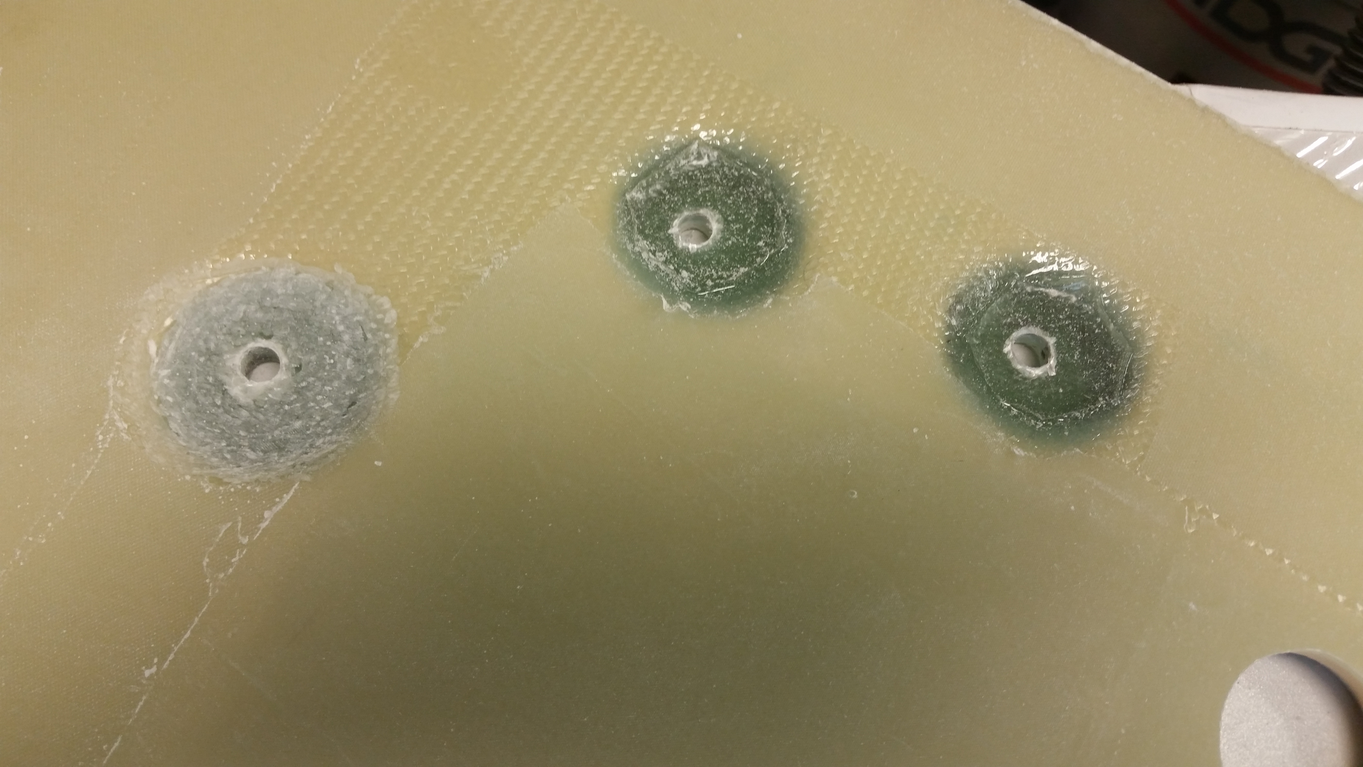
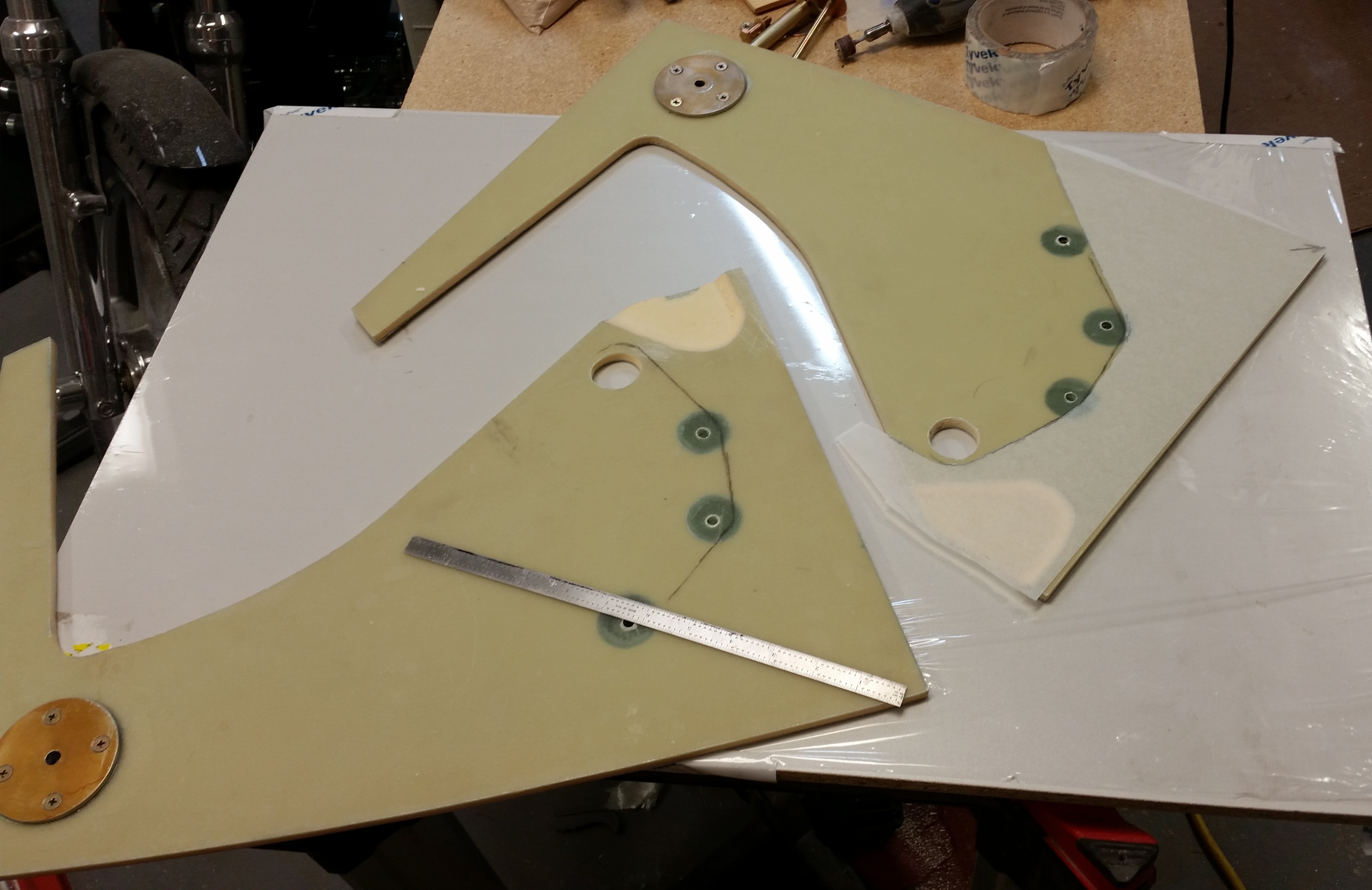
My specific steps today on the NG30’s was to fill in the 3 aft hard points with more BID “roundels” to bring the surface of each hard point up to the level of the surrounding NG30 surface.  Why?  Well, because I want to be able to use the correct washer and right now I either have to go with a smaller washer, or pack the hard point depression with flox before I add the washer.  Thus, in my mind it made more sense to just add a few more layers of BiD into the hard points.

Since I’m adding glass to the hard points, I am following the advice that Jack gave me during a conversation a few years ago by adding 1 ply of UNI at a 45° bias angle from the F22 junction down toward the front of the NG30 (just aft of the NG8 screws).  And then on top of the UNI will go 1-ply of BID that also goes right up to the NG8 area. To be clear, Jack had mentioned this as part of a few possible, but not “mandatory,” mods to increase the strength of the NG30’s.  After reviewing my emails with Jack, and taking into account Jerry Schneider’s not too distant crunching of his stock NG30’s in his Cozy after a hard landing, I decided to employ all NG30 beefing up measures, weight be damned!!! (Forgive me Burt, for I have sinned . . . !)

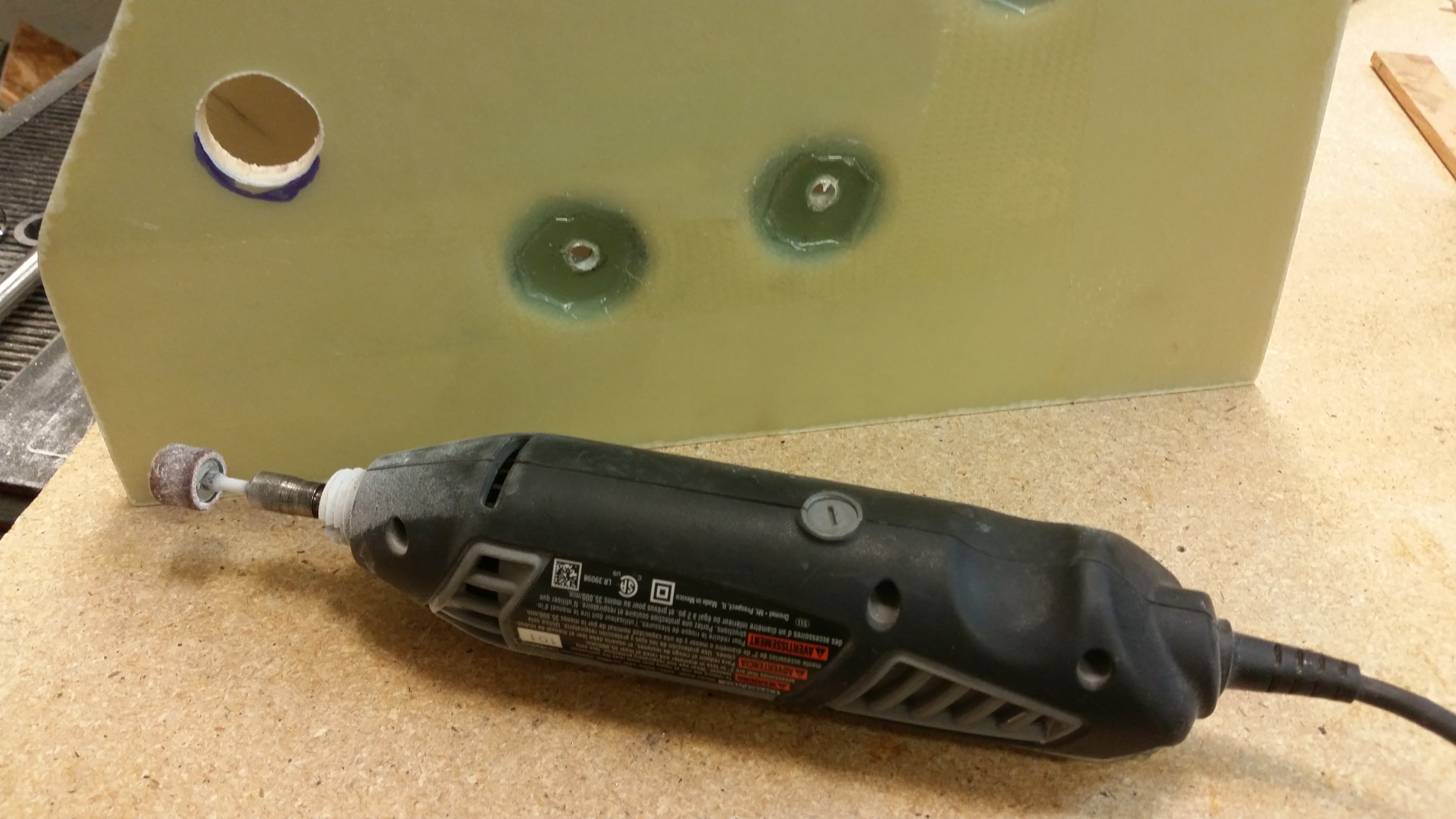
The first task was to clean up the excess epoxy and prep the glass for adhesion using the Dremel tool.  One point of note is that when I originally built these NG30 hard points, I did them to plans so I put weights on them to compress the glass.  Boy did it ever!  Plans say to glass in 15 plies, and I ended up adding at least another 3 plies.  Well, the weight really worked, and the top of each hard point is still well below the surface of the NG30.  Great for strength but bad for washer positions!

Below shows a progression of me cleaning up the NG30 aft hard points with the Dremel tool.

Roughing up NG30 hard points

NG30 hard points roughed up

ALL NG30 hard points roughed up

After I got the hard points cleaned up, I then sanded & prepped the surface of each NG30.

Outboard NG30's sanded & prepped

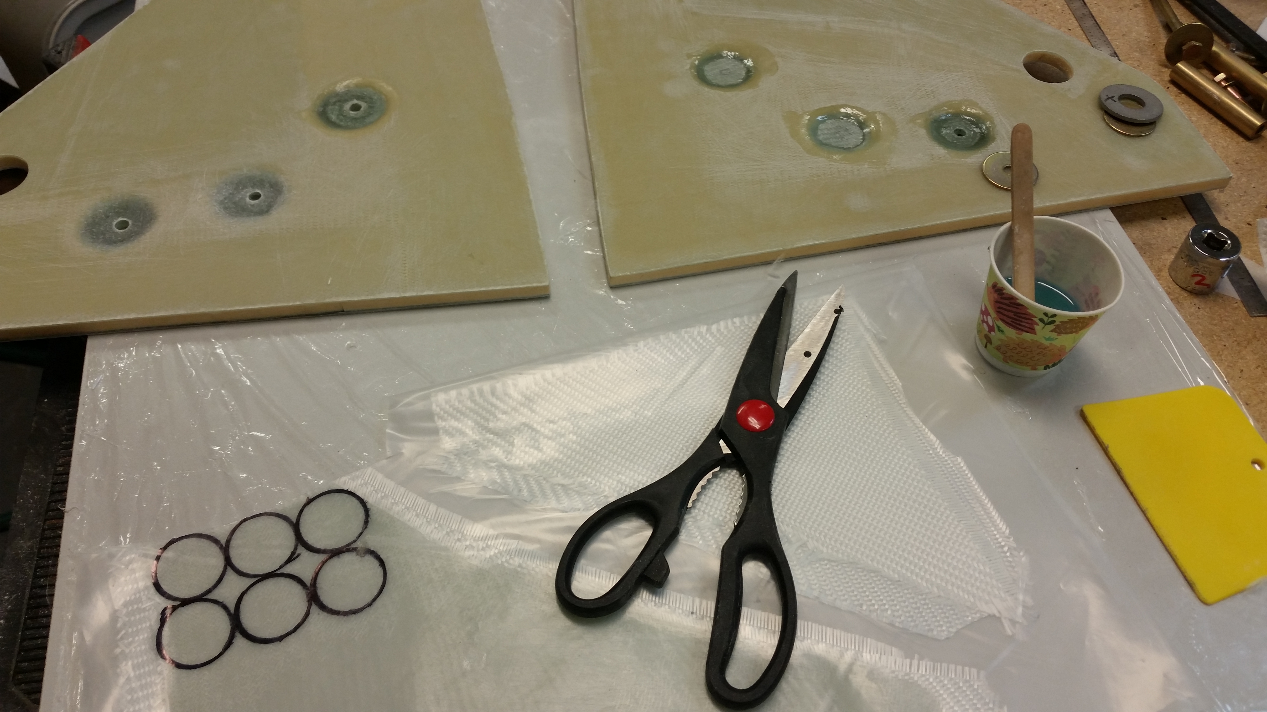
I then grabbed some scrap BID to use in the pre-preg for the hard point “roundels.”

Glass for hard point roundels

Here’s a shot of the BID glass “roundels” getting cut and glassed in place.  I have to say that I thought most of the hard point depressions would handle another 6-8 plies of BID, but by the time I got to laying up the UNI pieces on each side, I would have to say I added about another 10 plies into each hard point depression.

Adding glass plies to hard point depressions

Below is my finished NG30 quest for the evening.  Each NG30 has 1-ply UNI at 45° bias (as per discussion with Jack) & 1-ply BID over the now surface level glassed hard points.  Then I peel plied the entire layup mainly to match the original layup surface texture.  Of course I’ll also be adding a number of BID tapes to these in the nose build process.

Outboard NG30s glassed 1 ply BID + UNI

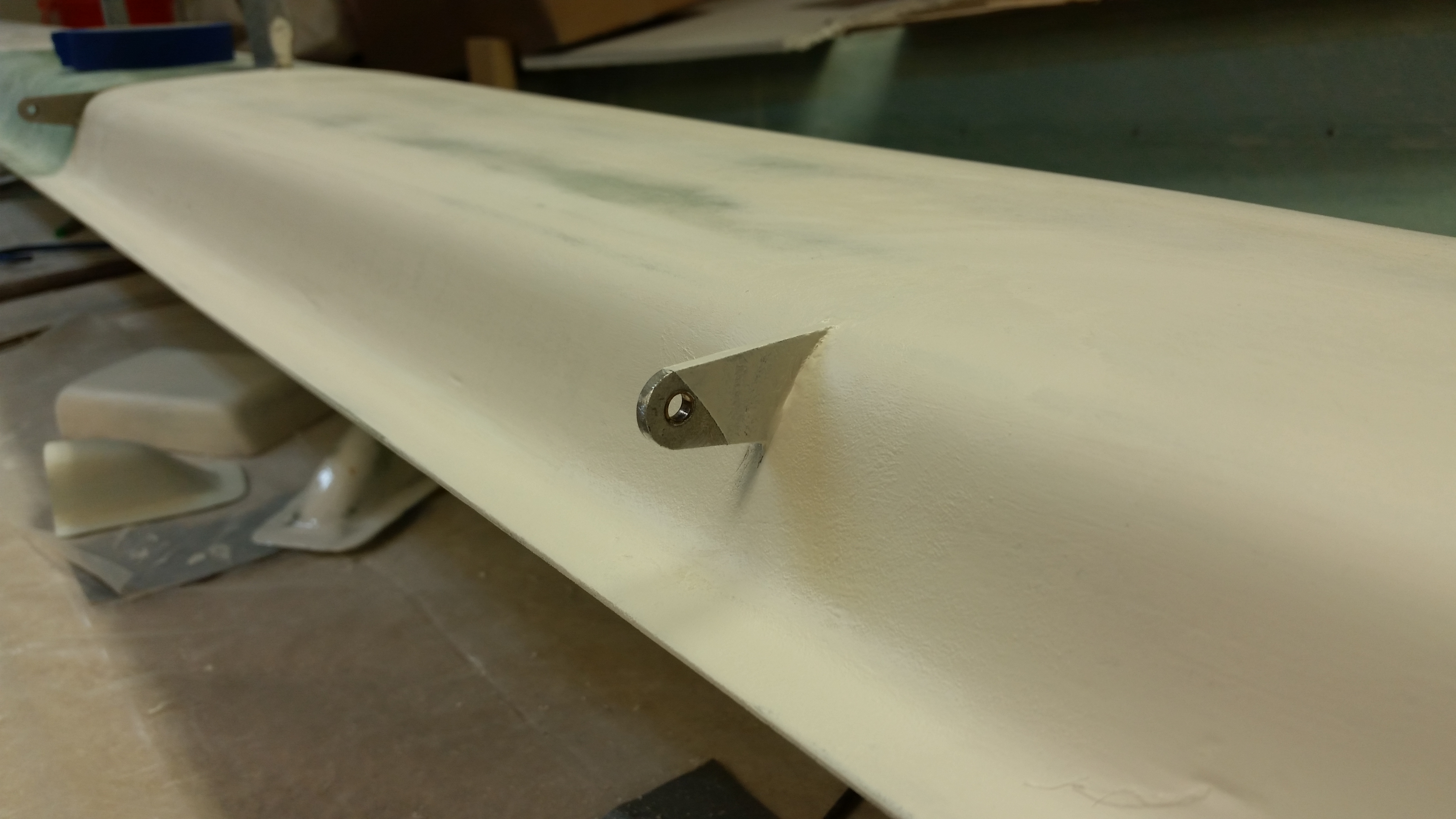
I took quick shot of inboard side of canard swoosh tip area to show what it looks like.  Note that I taped up the end of the hinge tab to prime it.

Primed canard tips & inboard area

And here the tape is removed and you can see that the majority of the hinge tab is primed.

Primered elevator hinge tab

Tomorrow I plan on cleaning up the NG30’s by pulling the peel ply, razor trimming the edges and ensuring the layup was good.  I then plan on sanding the primer on the canard, and hitting whatever spots on the canard bottom that need another coat of primer.  I will then knock out the fuselage dolly.


Chapter 13 – Much ado about a lot!

I started off this morning working for about an hour on some build project housecleaning duties such as updating my spreadsheet with recent purchases, and my project “Order of Battle,” and my specific to-do lists for each chapter.

After getting the paperwork out of the way, my first priority of the day was to work on all the stuff that makes noise.  If noise wasn’t an issue, I would have worked on the canard first, then the nose NG30’s, and then the fuselage dolly.  But, since I can’t be making enemies of all my neighbors, or keeping the neighborhood awake with my plane-building shenanigans, then I need to prioritize to get my clanging & banging finished ASAP in the day.

I started off today working on the NG30’s for the nose.  I needed to get some minor stuff taken care of so I could glass the aft inboard side with a 2-ply BID layup.  This layup would serve 2 purposes:  1) It covers the depression made in the upper aft area of each NG30 to allow freedom of movement of the nose gear actuator housing, and 2)  It reinforces the aft inboard edge of each NG30 with 2 plies of BID to strengthen the NG30 when attached to the center post of F22.  This was a recommendation I received from Jack Wilhelmson back in 2012, so I of course complied!

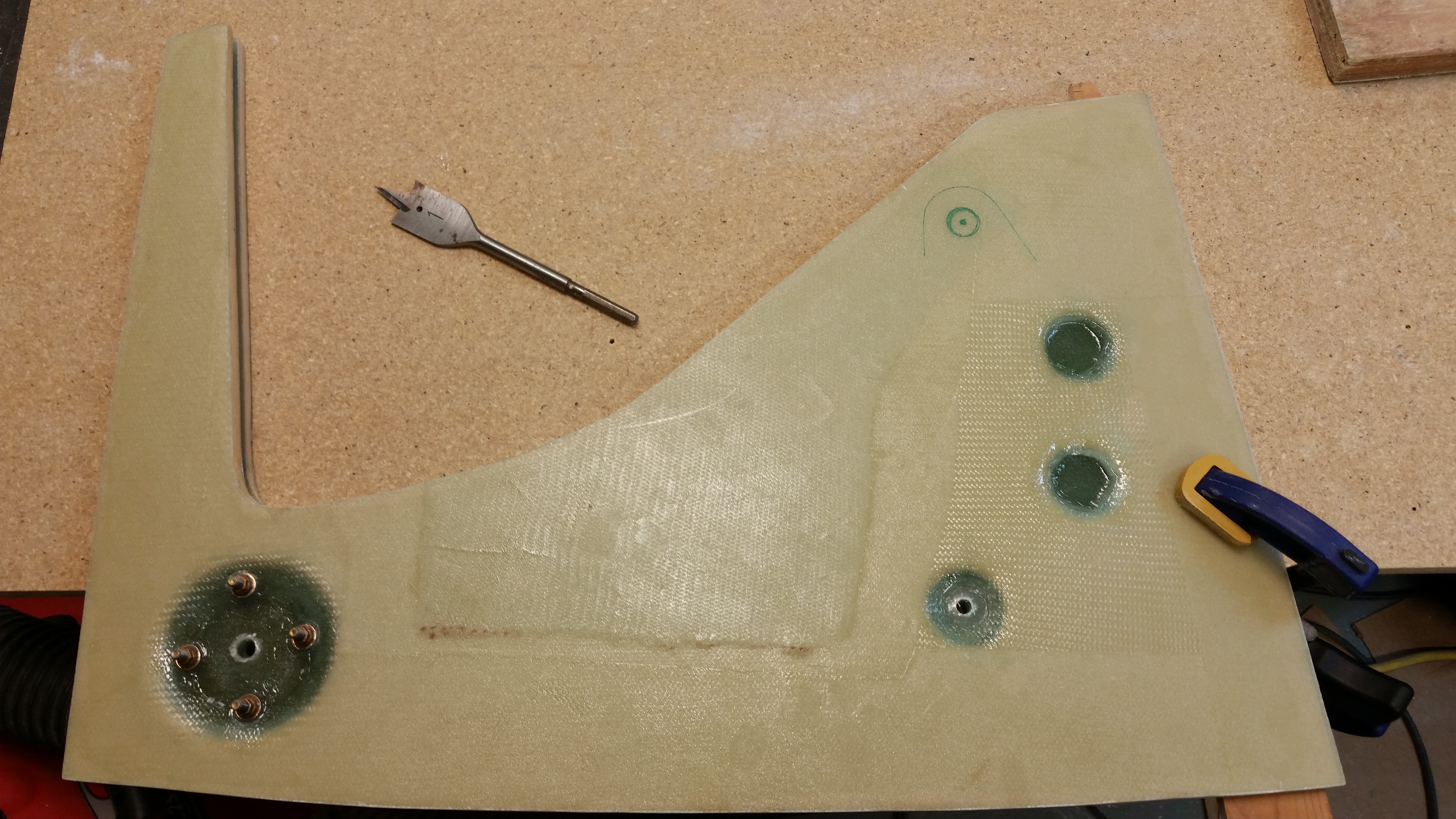
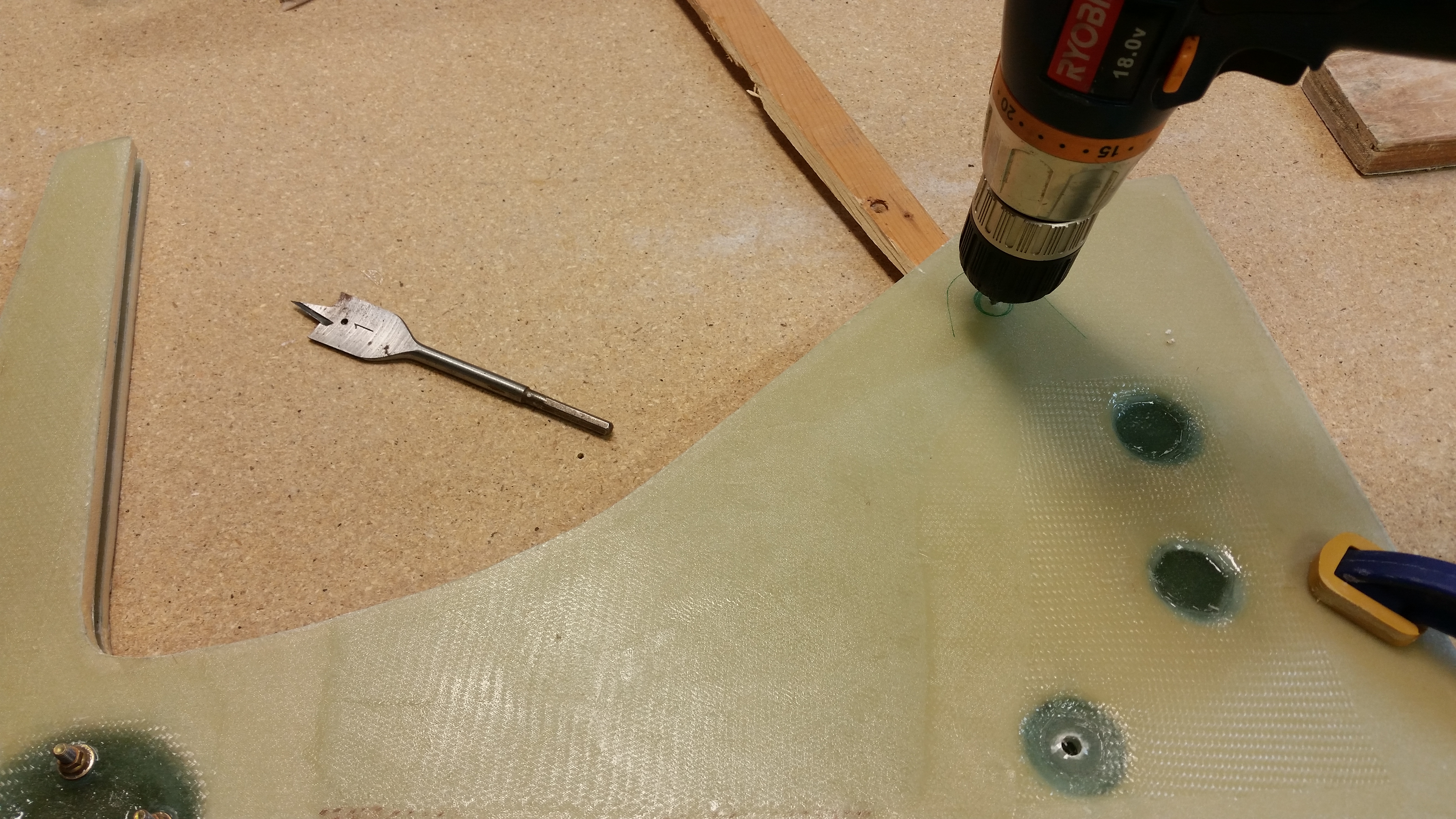
The first of this required stuff was to drill the 1/4″ holes for the actuator mounting brackets in the right NG30, by using the left NG30 as a template to make sure the holes are perfectly aligned.  Once the NG30’s were aligned and clamped it took very little time to drill the holes.

Drilling holes through to #2 NG30

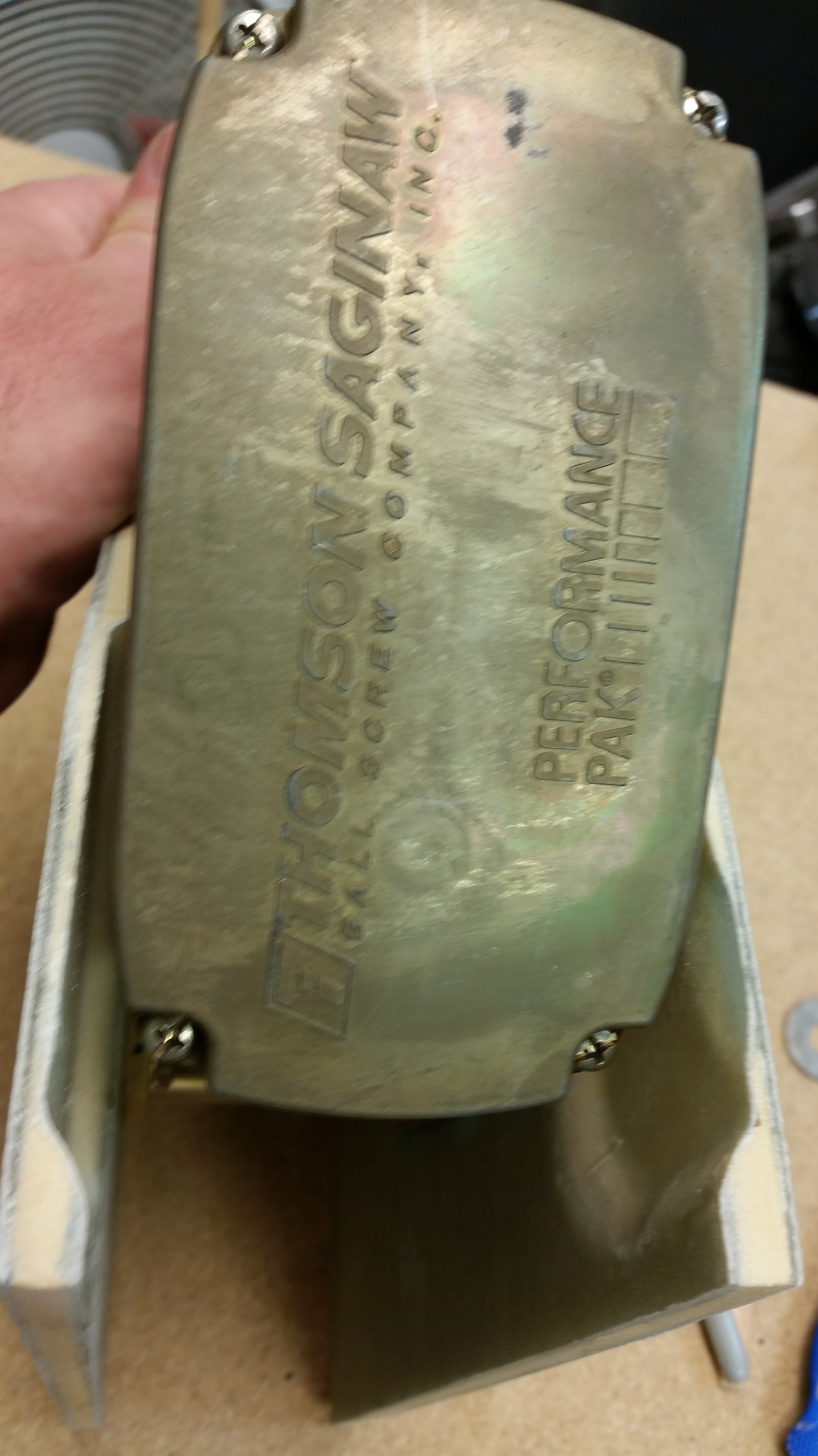
The next order of business was to expand the NG30 upper holes that provide clearance to the main nose gear actuator connect bolts.  This expansion is a result of the boo-boo that I mentioned earlier where I overlooked Jack’s mandate that the holes on the edge of the actuator mounting brackets are required to have 3/8″ clearance from the edge of each bracket to the bolt hole.  I’m fairly certain I was using the original holes shown in the old plans NG51s (mount for mechanical nose gear retract assembly) for reference, and those didn’t have the proper clearance.  The bottom line is that since I had to move the holes on the mounting bracket further away from the edge, it caused an issue of bolt clearance in the very top open hole.  It needed about 0.15″ more space at the aft end of the hole.

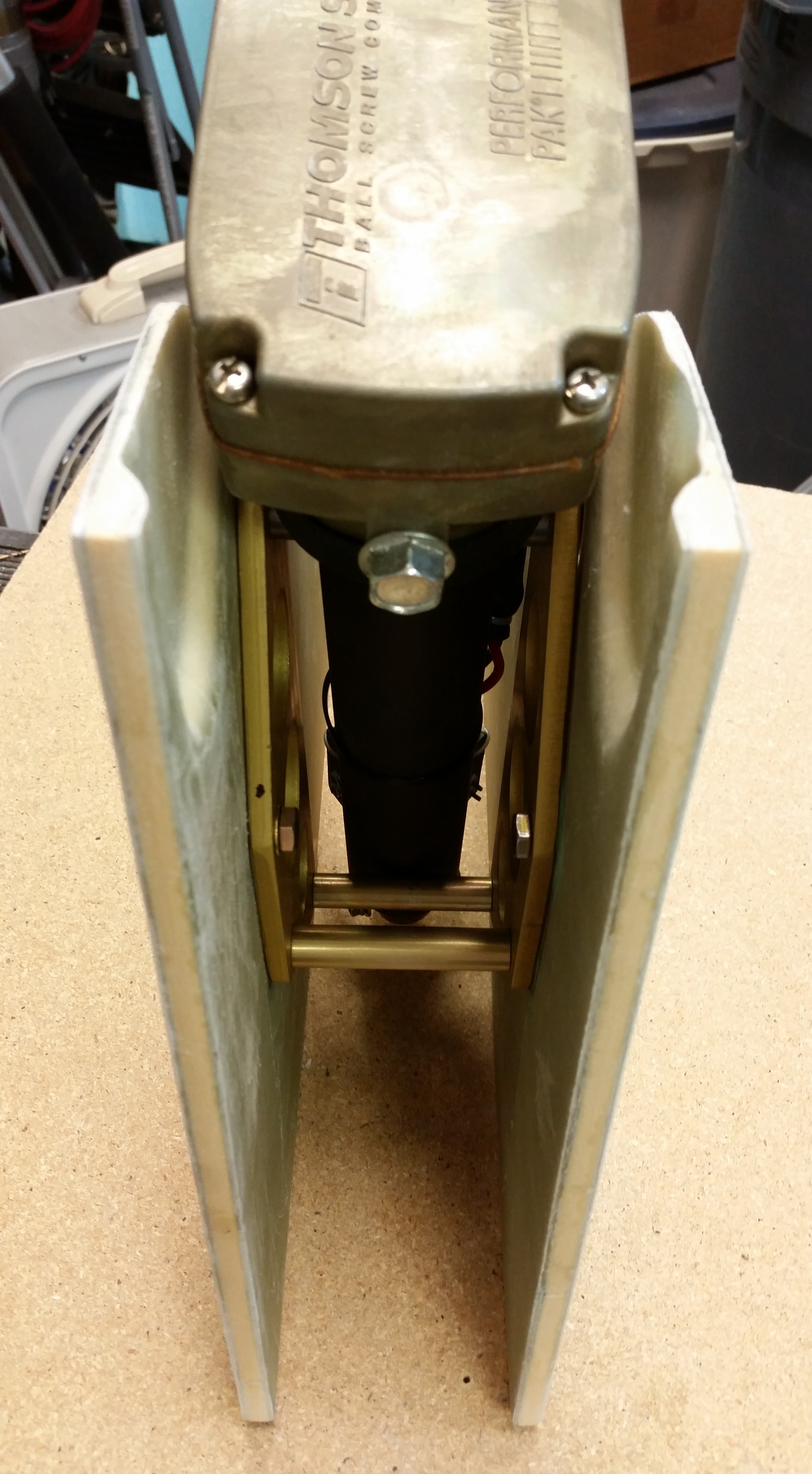
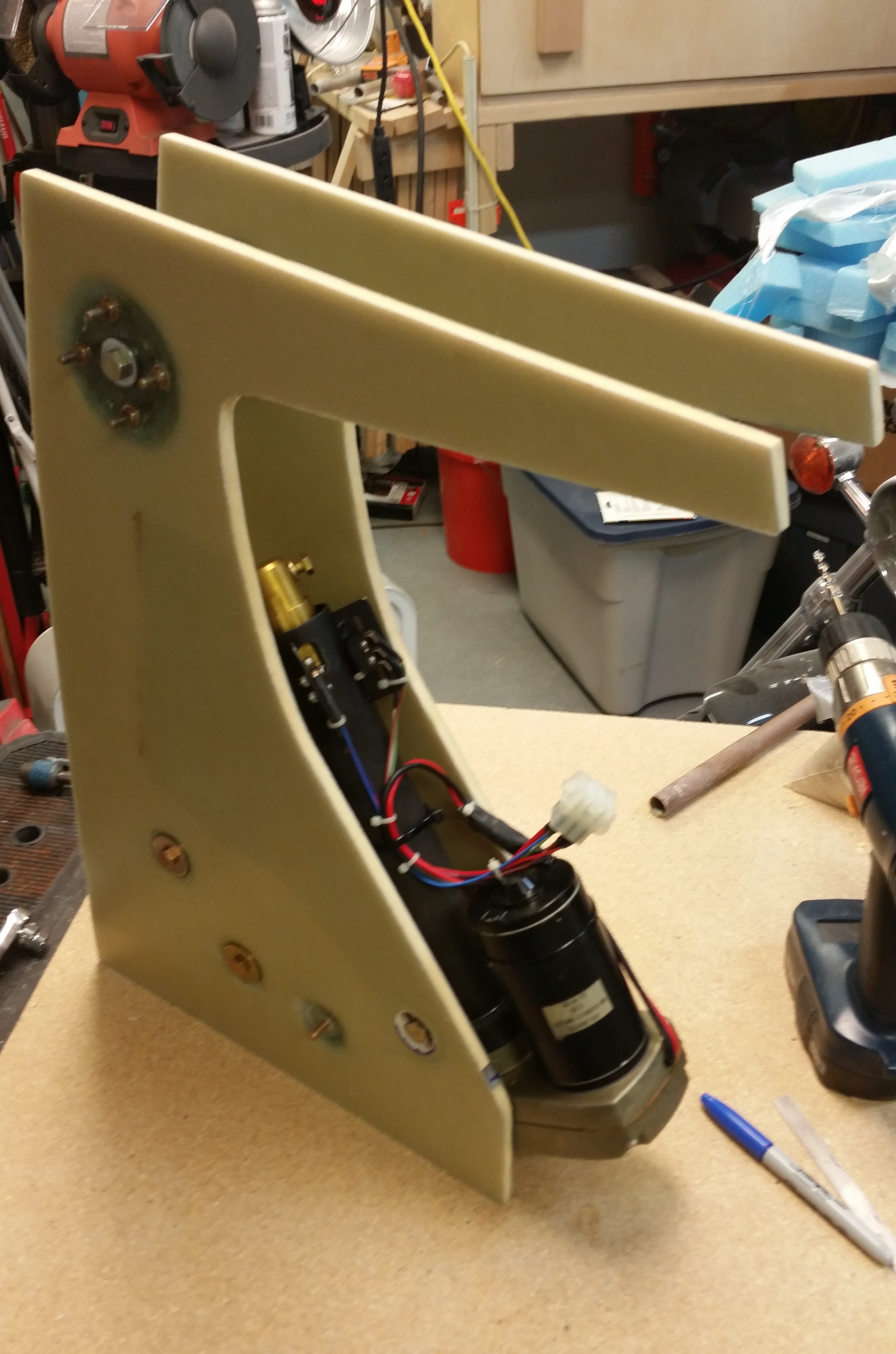
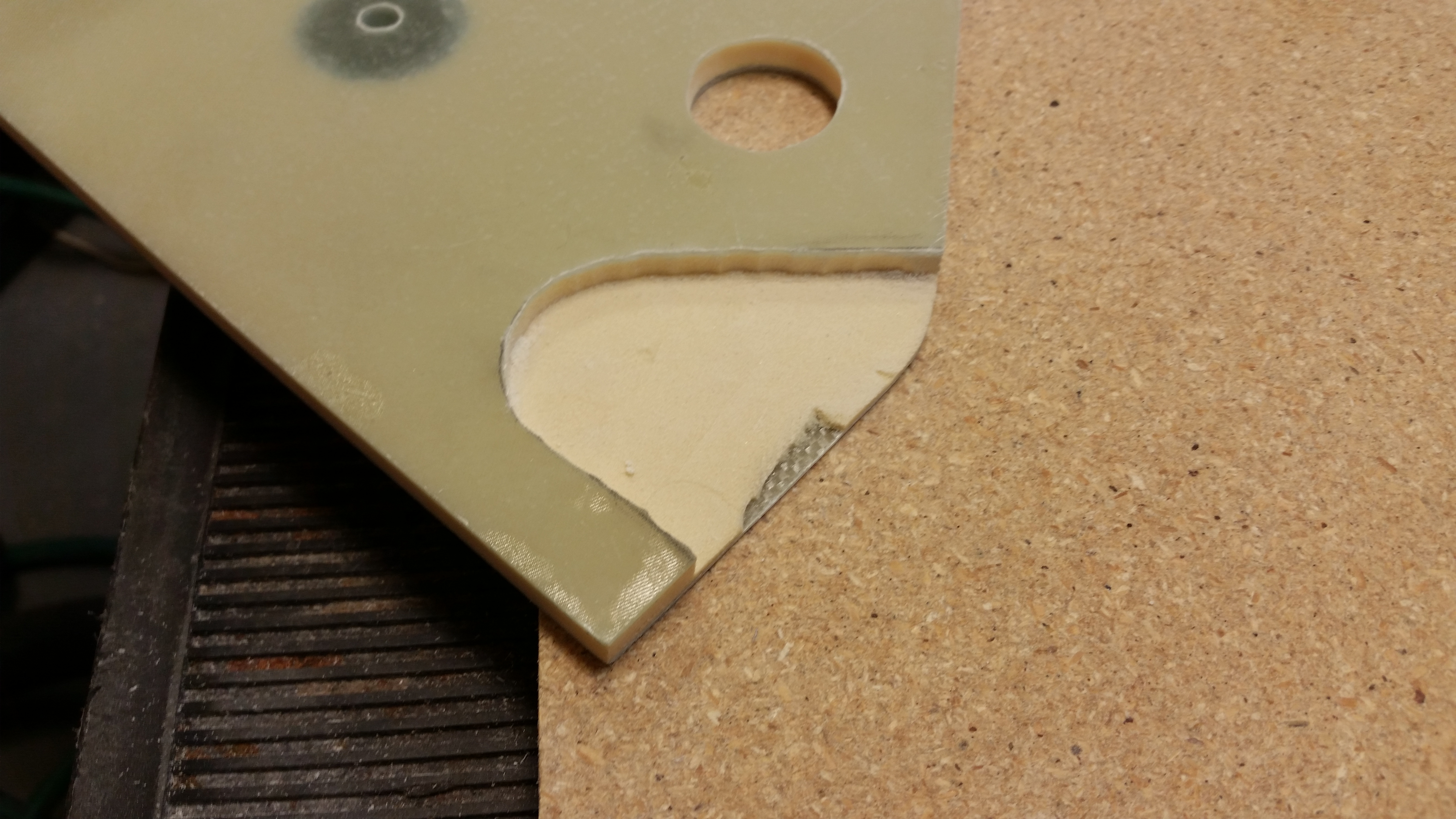
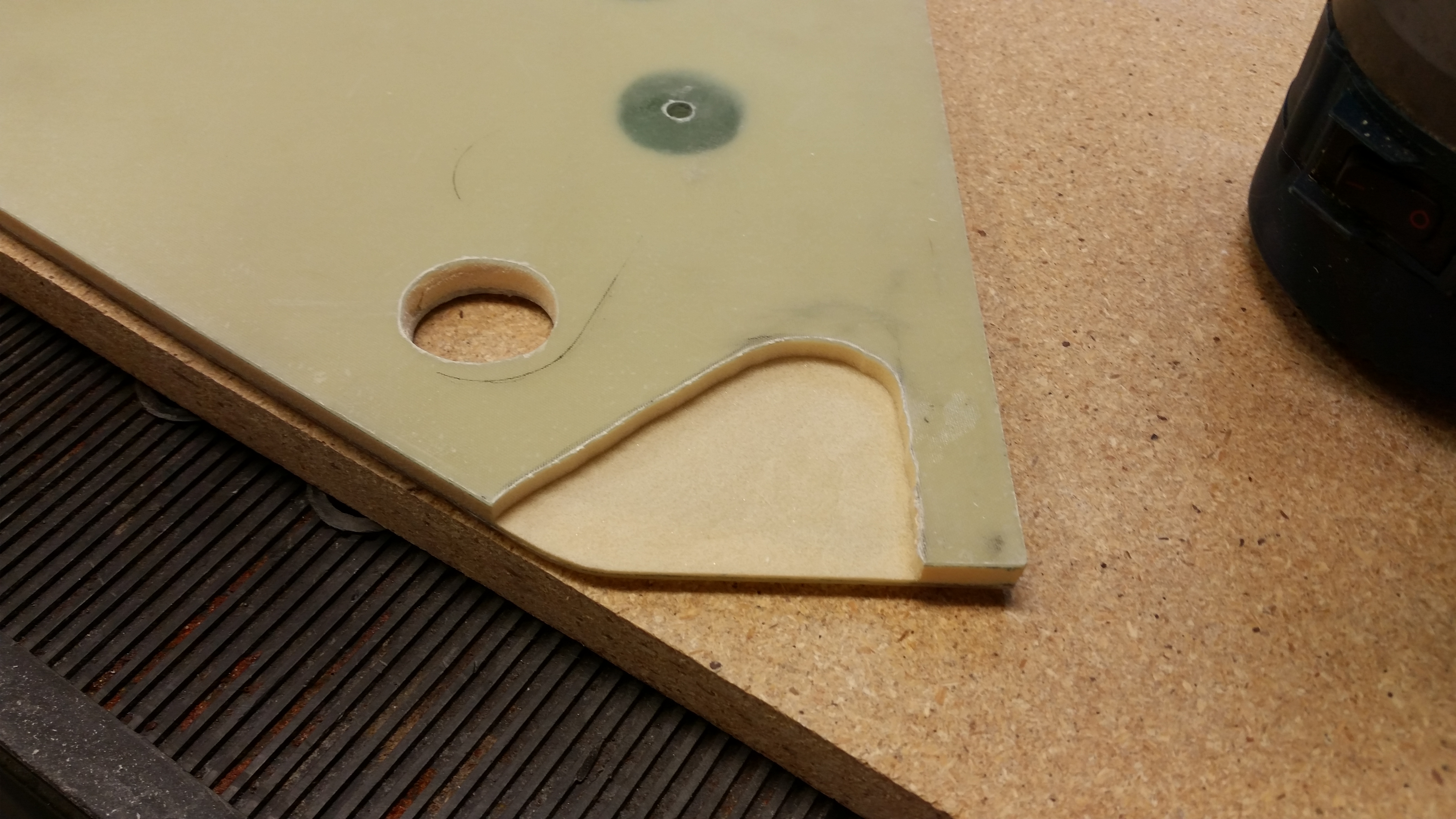
As I was checking the spacing on the upper NG30 hole below with the actuator installed (see pic below), I also marked off the area of the upper NG30 that needed to be removed to allow the proper clearance of the nose gear actuator top motor housing (the anodized gold cap at the bottom of the actuator in pic below).

Checking gear actuator clearance

Here I’ve prepped the Dremel tool to use on expanding the upper holes.  The area marked at the bottom of the hole is the offending mass that must be removed!

Enlarging gear pin holes

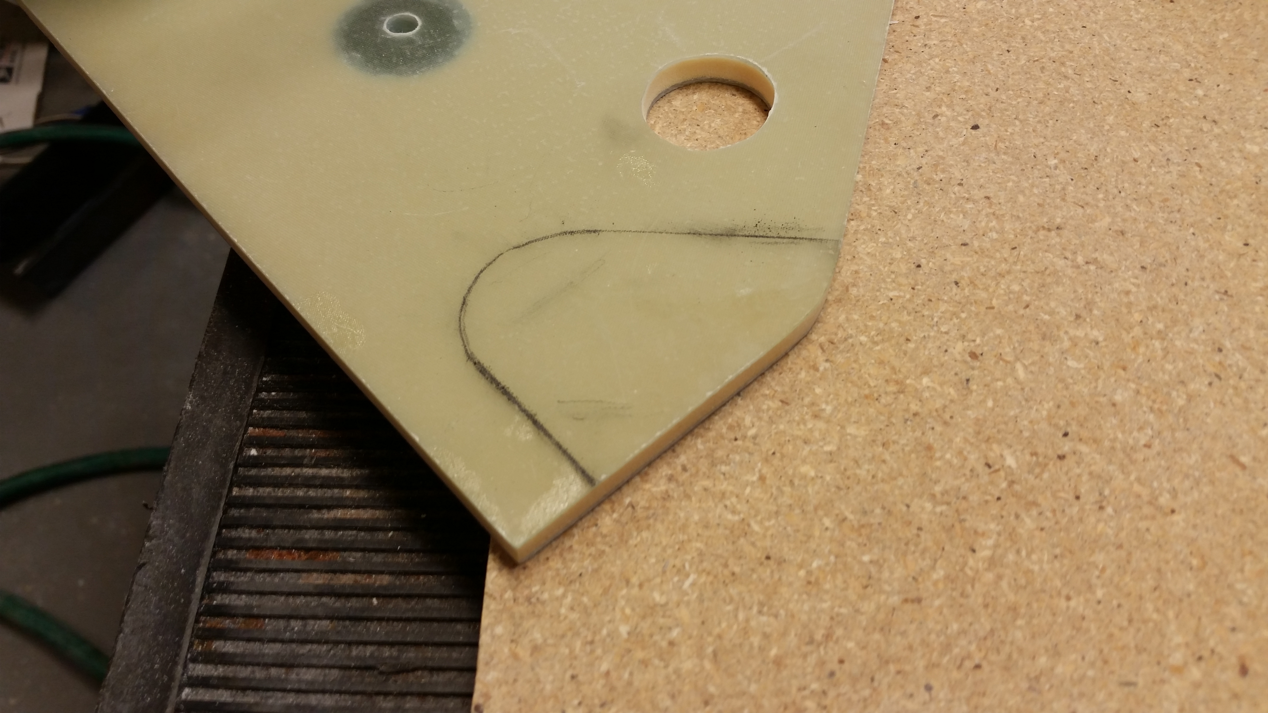
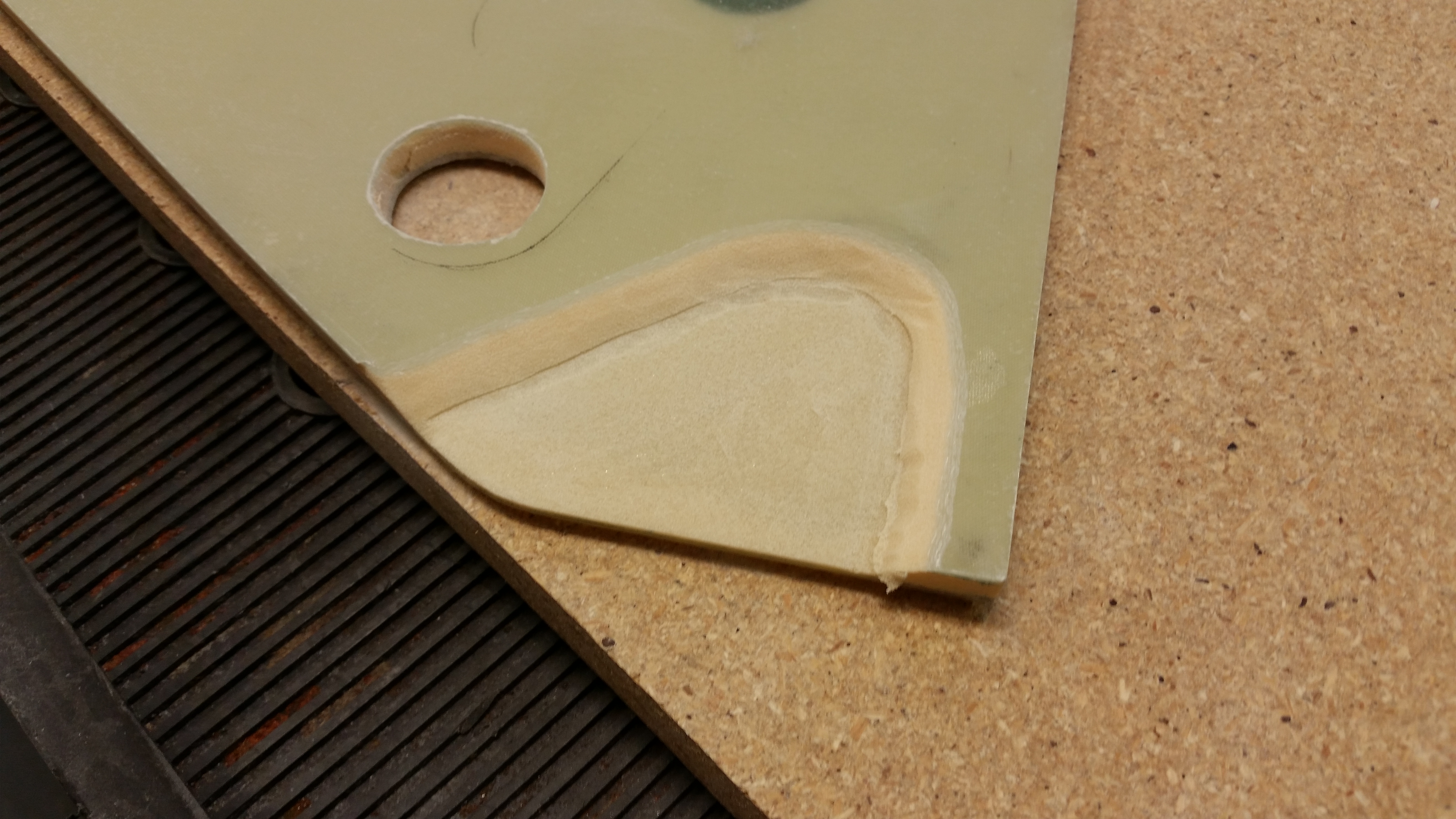
The last task on my list before glassing the inboard NG30’s was to remove the area that I had marked off above to allow unhindered movement of the nose gear actuator.

Prepping to dish out NG30

I used my router with a 3/8″ “square” bit and freehanded the cutting into the NG30 tops.  I set the depth at just a hair over 0.2″ (say, 0.21″)

NG30 top dished out for clearanceNG30 top dished out for clearance

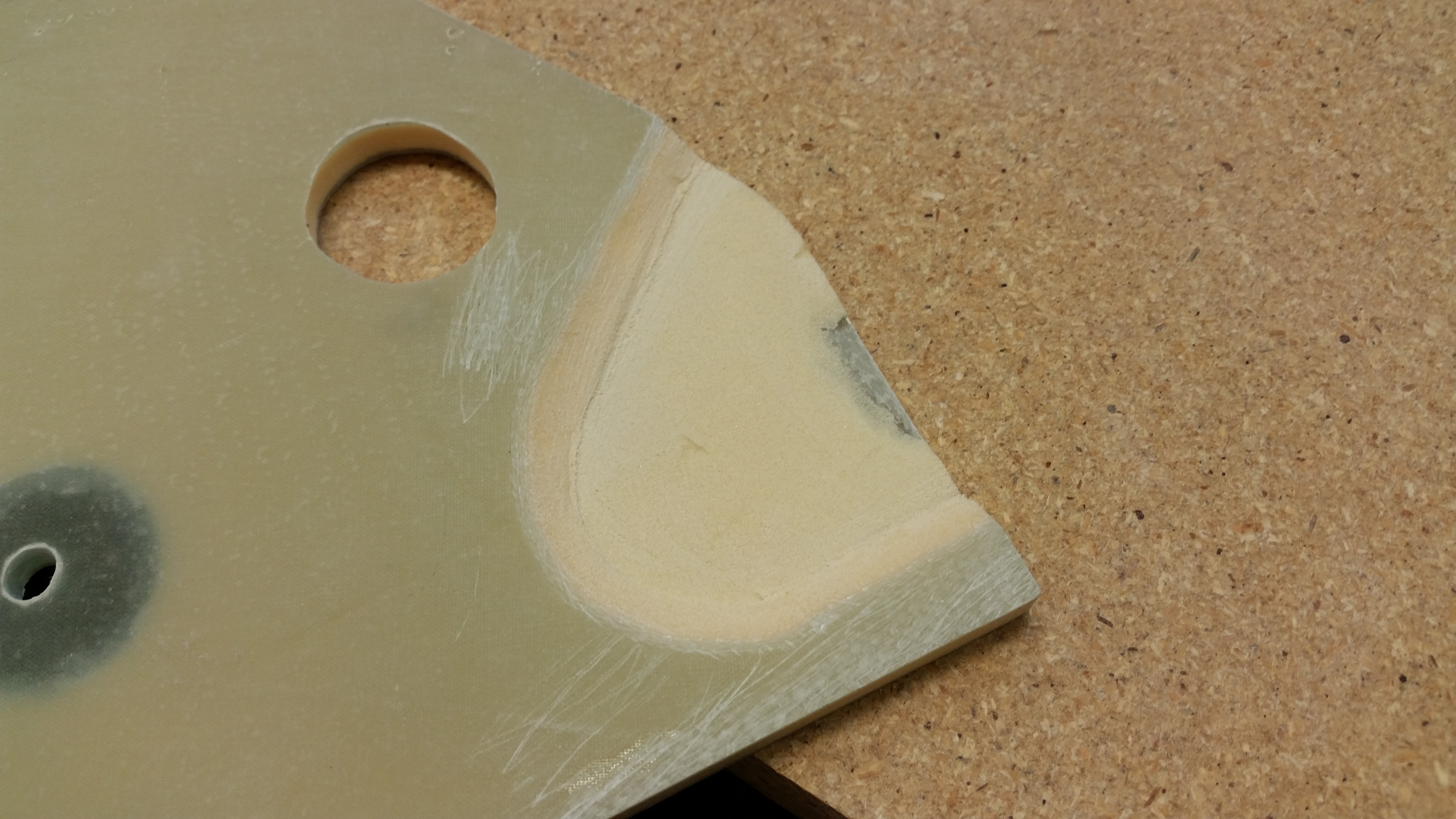
After using the straight bit, I used a “V” bit to bevel the edges of the depression.

Beveling NG30 for glassing

I then set everything back up to ensure that the top of the nose gear actuator motor housing had plenty of space, which it did.

Double-checking dished out areas

And I also checked that upper side holes provided the correct clearance for the main nose gear actuator attach bolt, which you can clearly see that it does below.

Side hole clearance is good

And finally, a shot from aft showing the clearance between the actuator motor housing and the sides of the NG30’s.

Actuator clearance is good

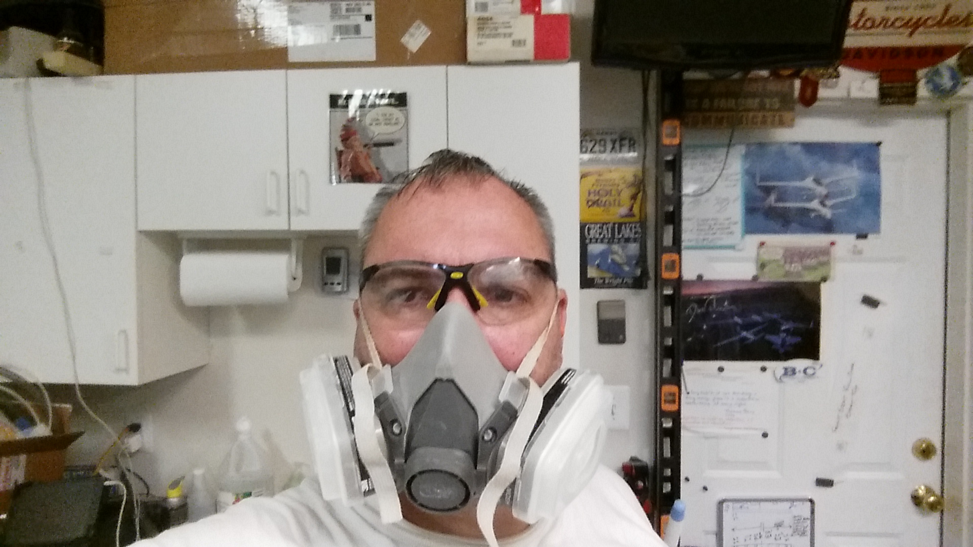
Here’s a couple of self portraits that I took with my Darth Vader-lite gear (I figure every now and again I should show the FAA that I was the guy actually doing the work!).

Me . . . at work!What my plane sees! HA!

And here are the depressions ready for glass after I refined the beveled edges with the Dremel tool.

Ready for glassReady for glass

With the glassing ready to commence, I needed to make a template of the areas I intended on glassing.  I wanted to stay clear of the gear actuator mounting brackets (that bolt into the 3 hard points) as to not mess up the set internal dimensions of NG30 components (e.g. relationship between actuator mounts at the aft end of the NG30s and the NG6B, nose gear strut pivot at the forward end of the NG30s).

Glass template created

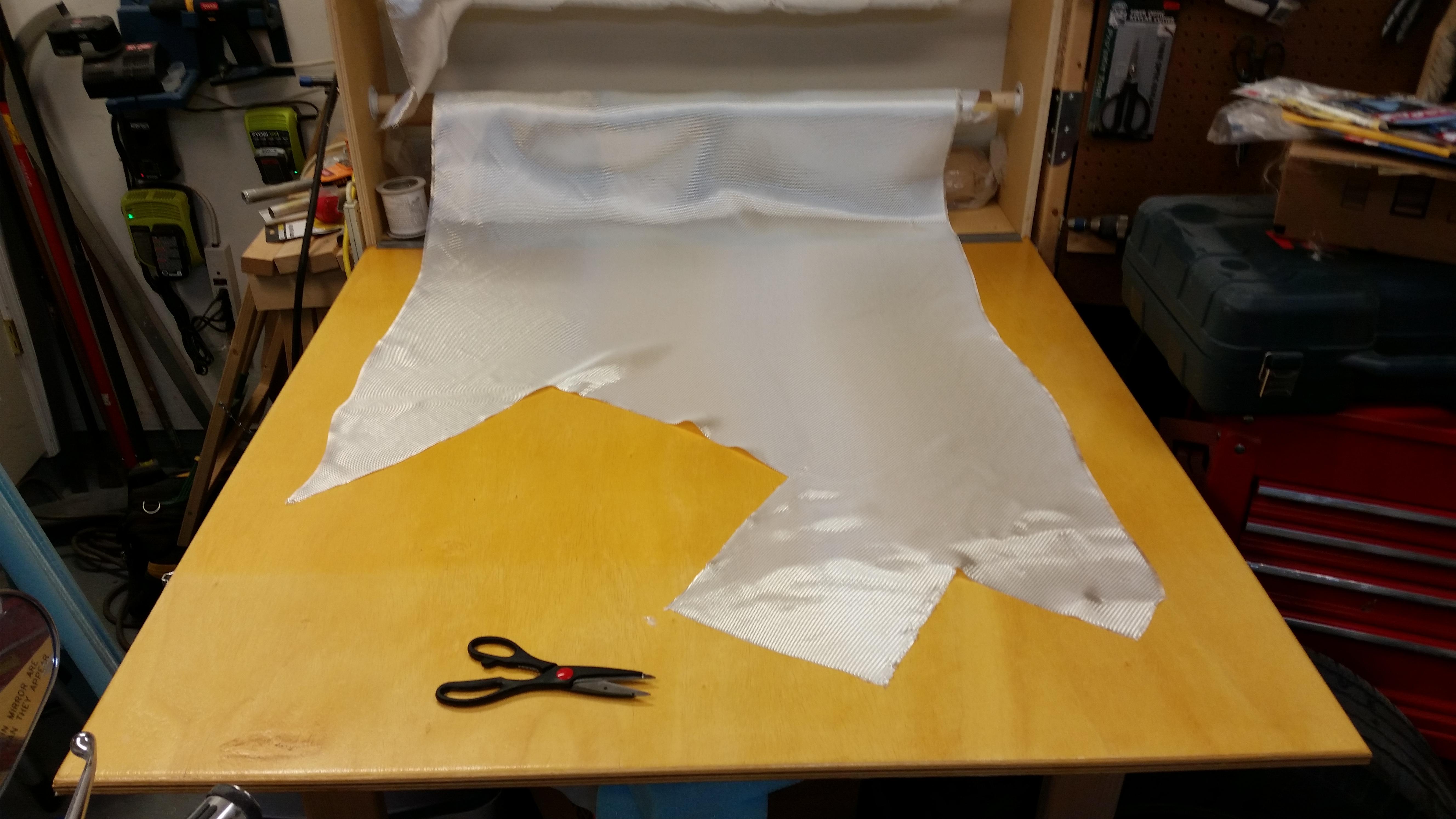
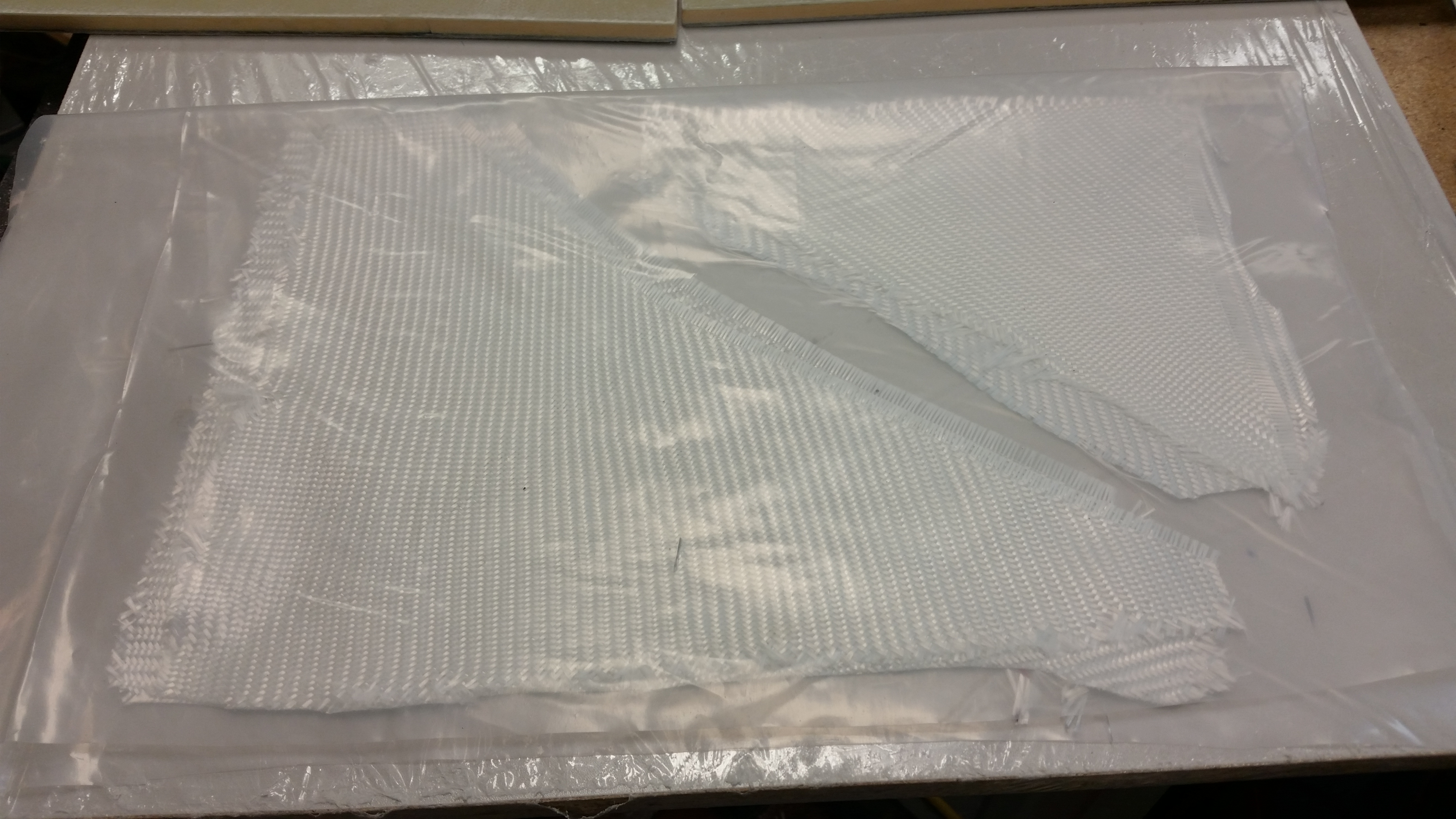
And then I had to do something that I haven’t done in quite a while . . . cut glass off the roll! After making the template, I calculated that I needed to cut two 15″ x 15″ squares of BID for the pre-preg setup.

What the…? Gotta really cut glass?!

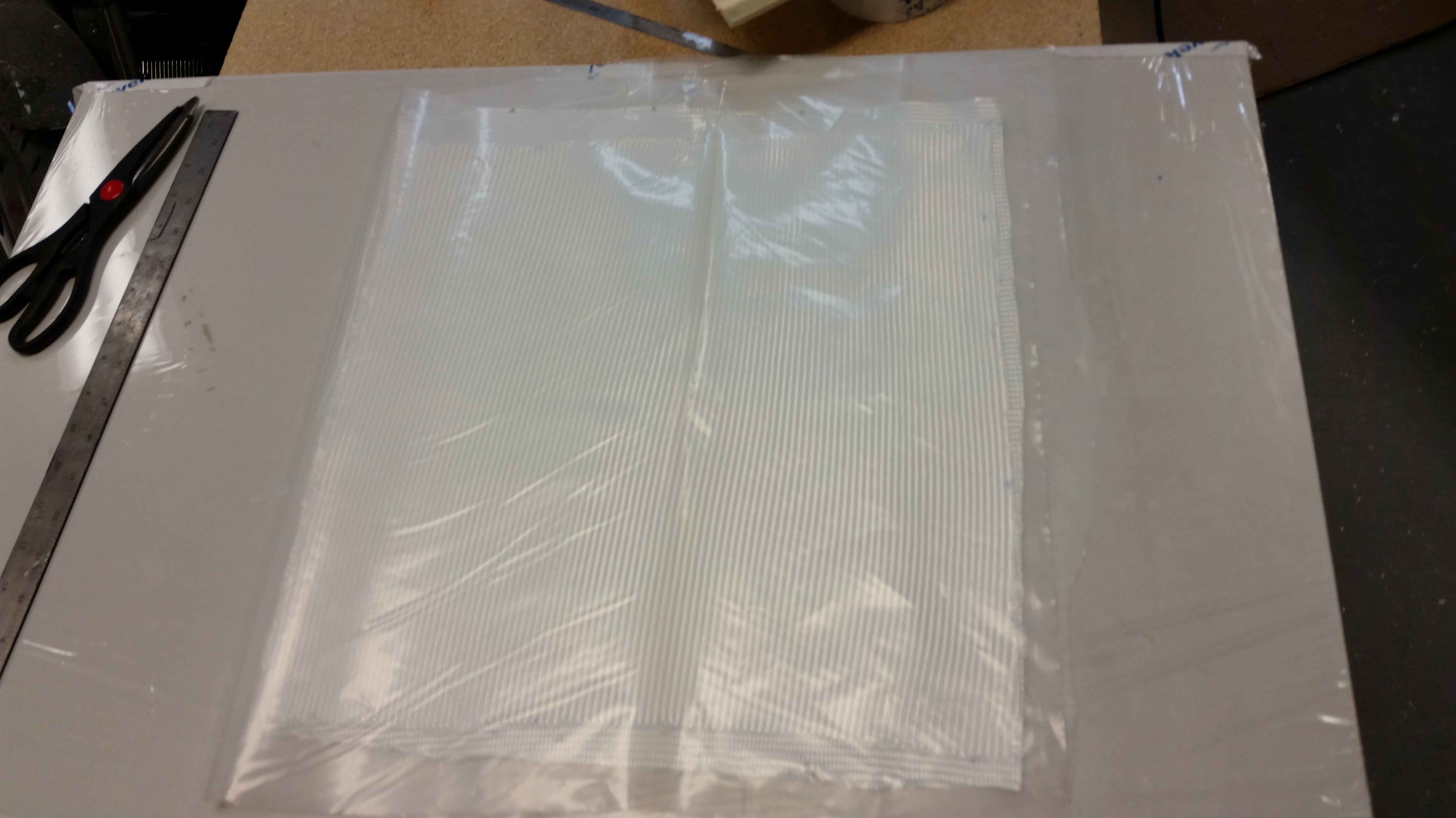
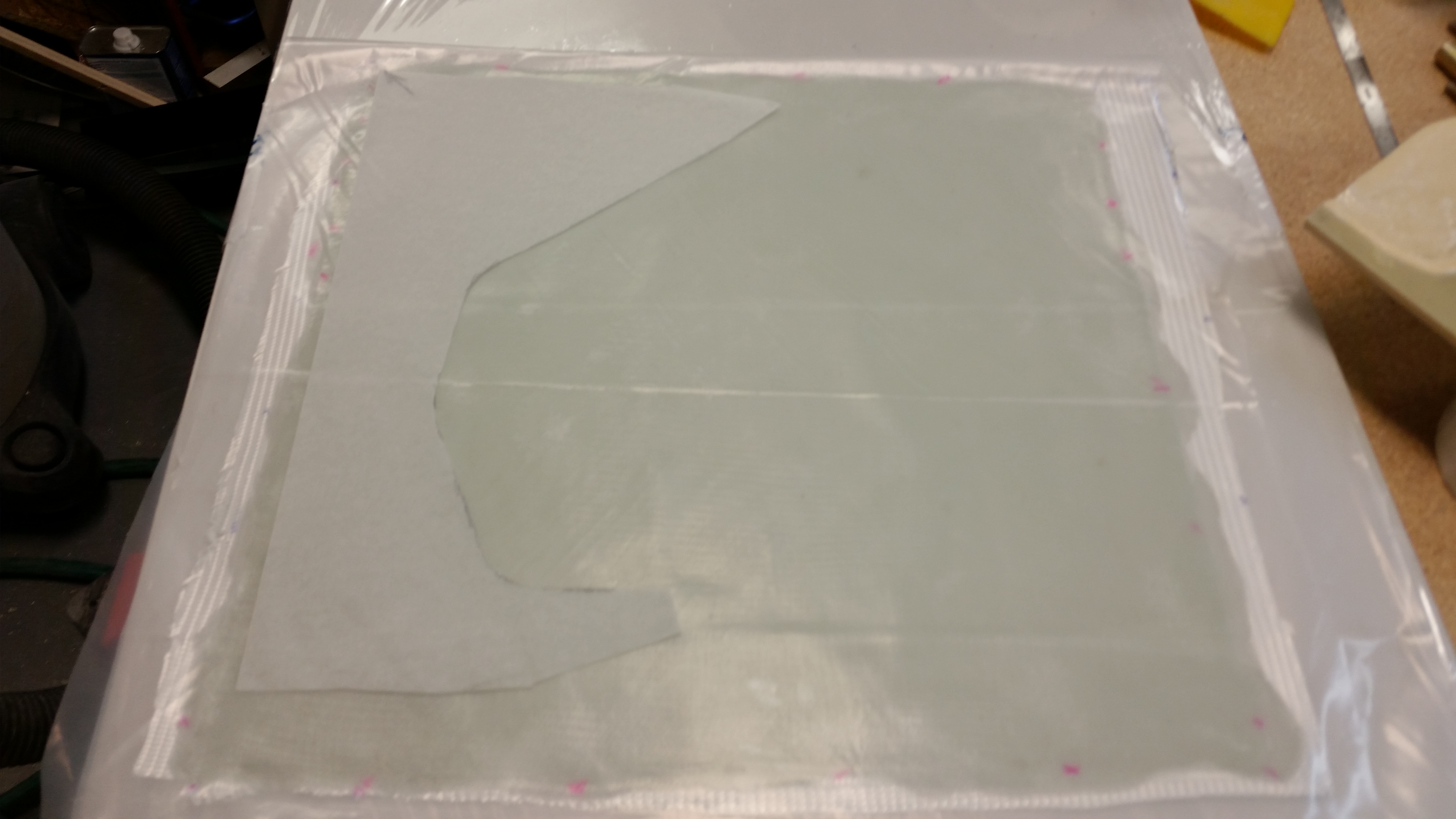
Here’s the 2-ply BID pre-preg (“poor man’s”) setup ready to go.

2-ply BID pre-preg

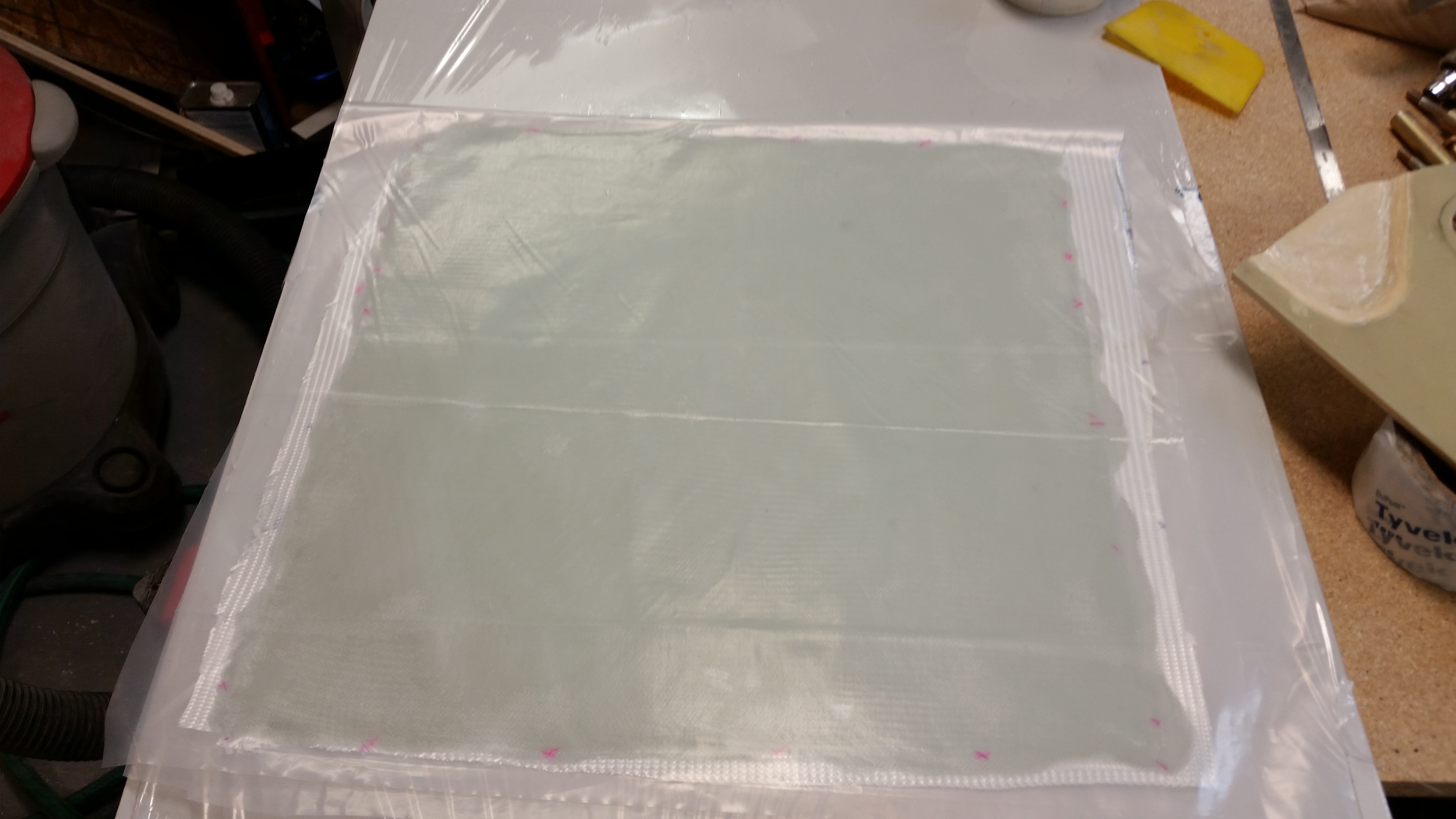
And then I added epoxy–using fast hardener–to wet it out.

Wetting out BID pre-pregWetting out BID pre-preg

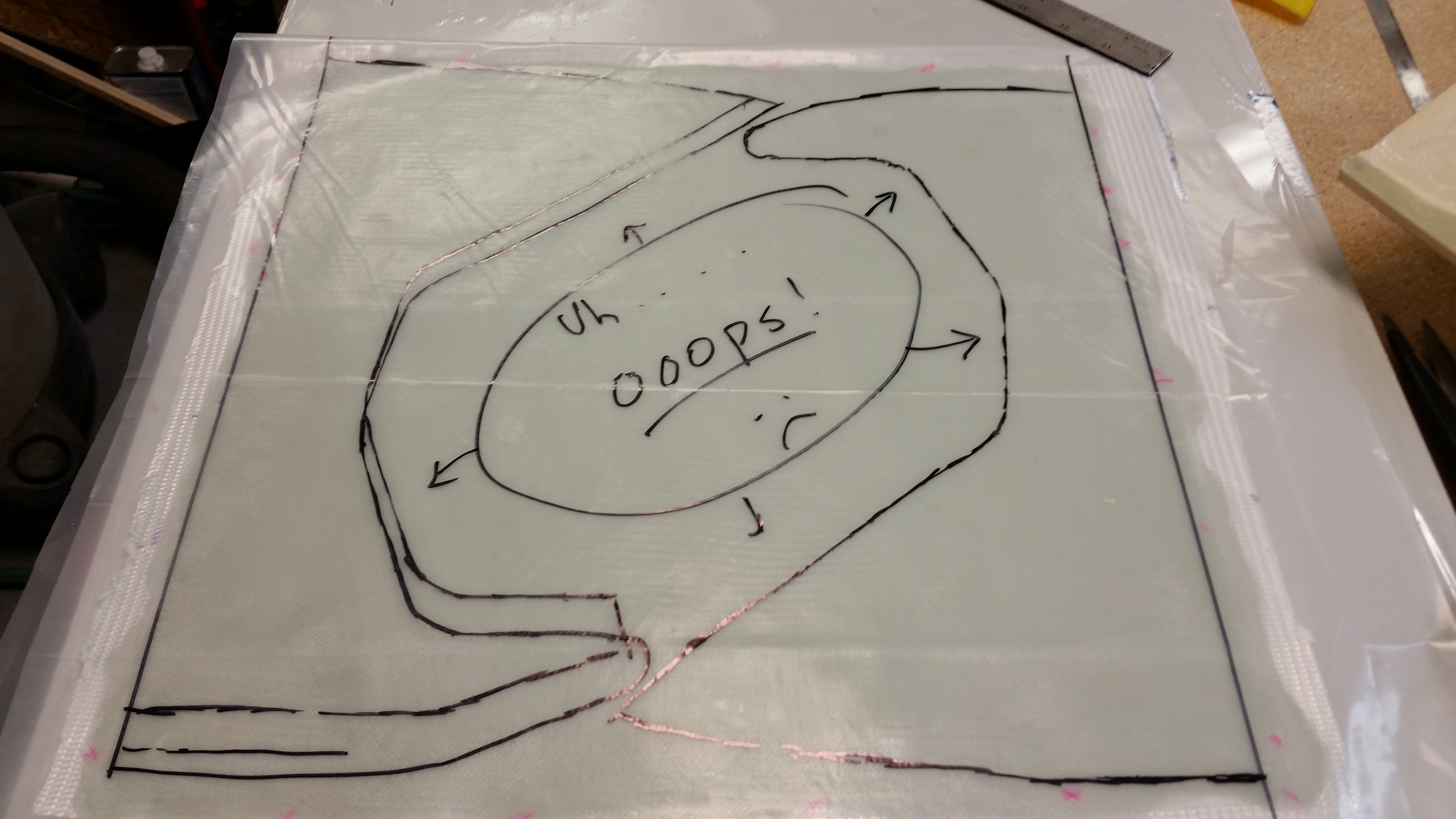
Once the BID was fully wetted out, I used the glass template that I had just made and cut out the two pre-preg setups for glassing the NG30s.

Template on BID pre-preg

I realized if I had staggered the sides a little better, I could have conserved more BID . . . oops!

Pre-preg ready to cut … really!!

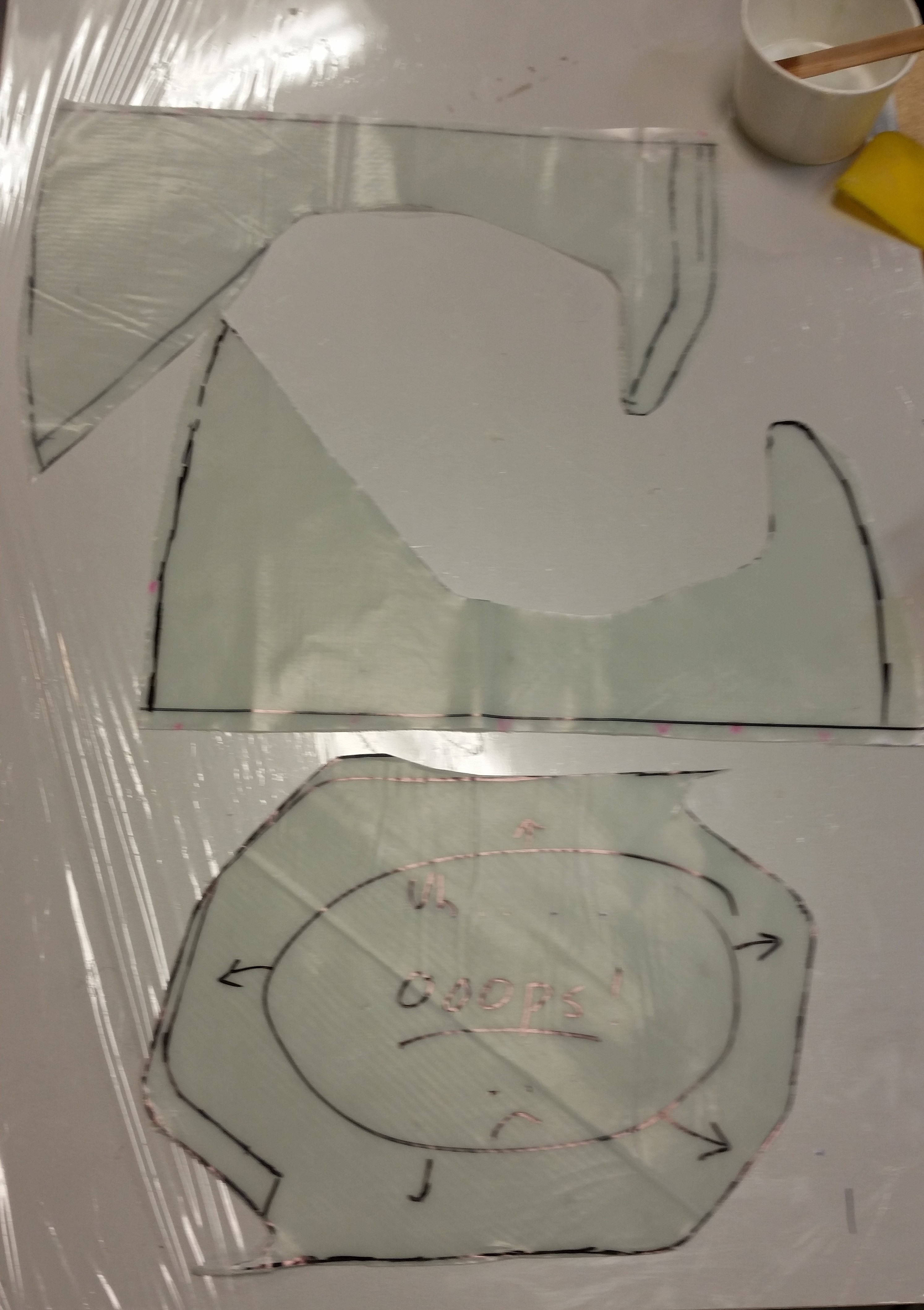
I then cut out the two BID pre-preg setups.

I set the “oops” section aside so it will cure flat, at which point I’ll use some of it later on by cutting it into 1/4″ strips to use as filler material when I have to increase the depth of both my stock strut cover (SC) and nose wheel cover (NB) that I bought from Feather Light… tweaking these parts is a second order affect that is a result of having to cut the gear strut channel deeper to get the nose wheel to set fully into the belly of the plane–which differs from the original plans where the nose wheel hangs down below the airplane by just a bit.

Pre-preg glass ready for layup

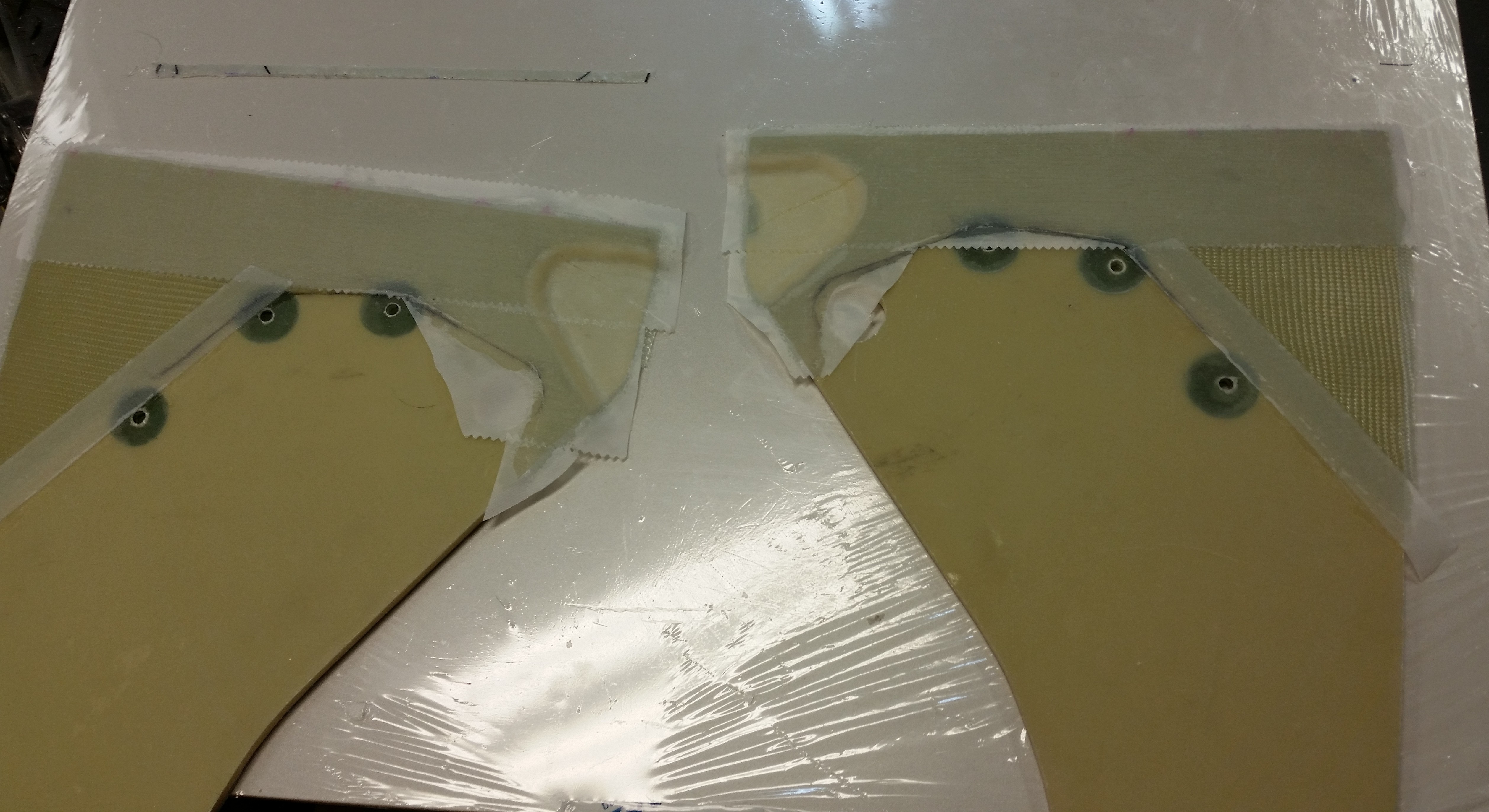
I then laid up the BID pre-preps on the inboard sides of the NG30s.  After ensuring the layups were good, I peel-plied the critical areas/edges.  As per my plan, I was able to just skirt the edge of the actuator mounts by about a 1/16″ to 1/8″.

Inboard NG30's glassed

I noticed after laying up the glass, that the glass at forward top of the depression would not lay flat on the foam on the right NG30.  I kept my eye on it and finally after messing around with the pesky glass for a few minutes, to no avail, I simply covered that area with Saran wrap, put some cushioning material on it to flatten out the invariable ridges from the plastic, and then threw a sandbag on it to keep the glass weighed down while it cured.

Destroying a pesky air bubble!

Now, onto more noise-making activities!

I pulled out the big dog to make some real noise!  This sucker will cut anything!

Pulling out the Big Guns!!

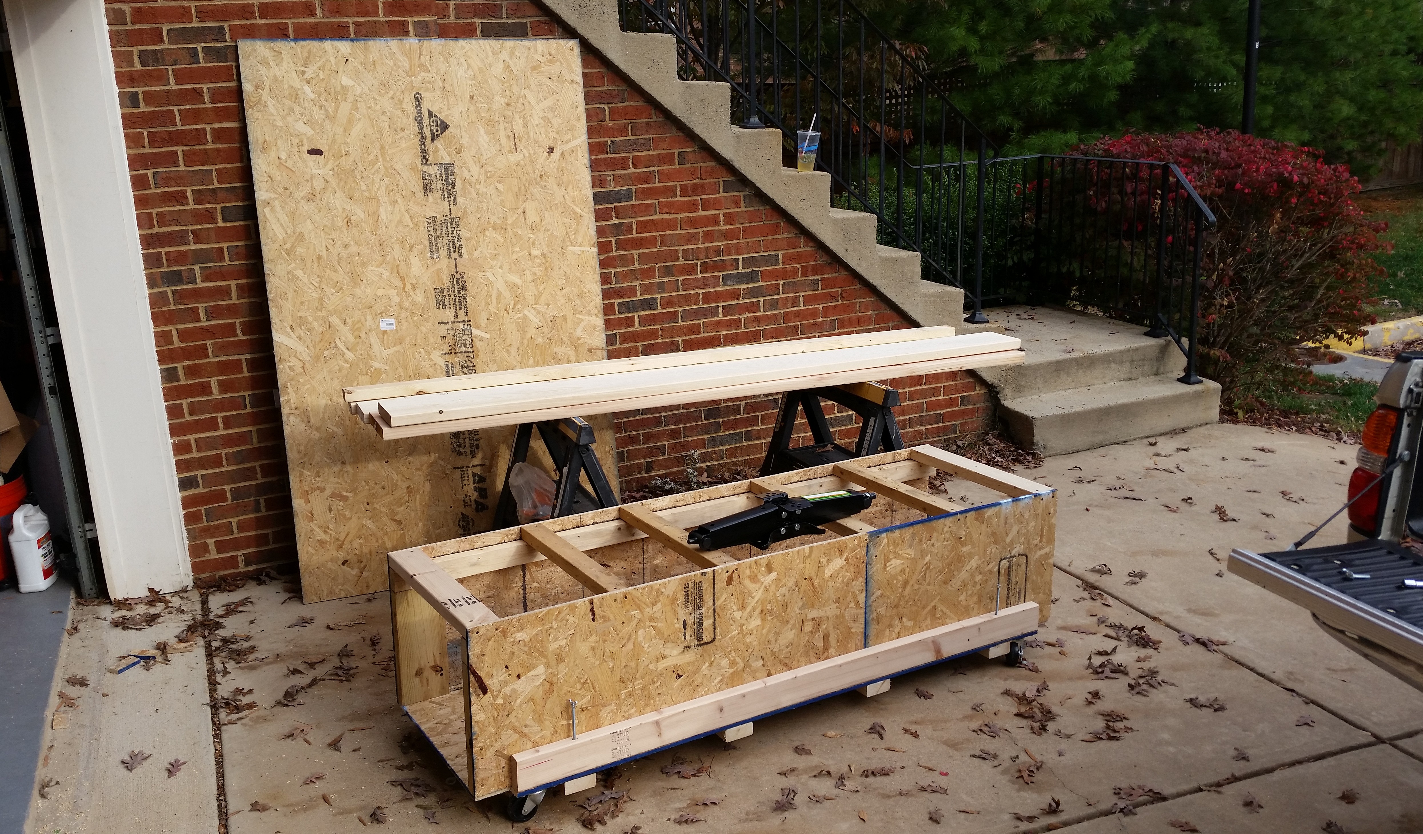
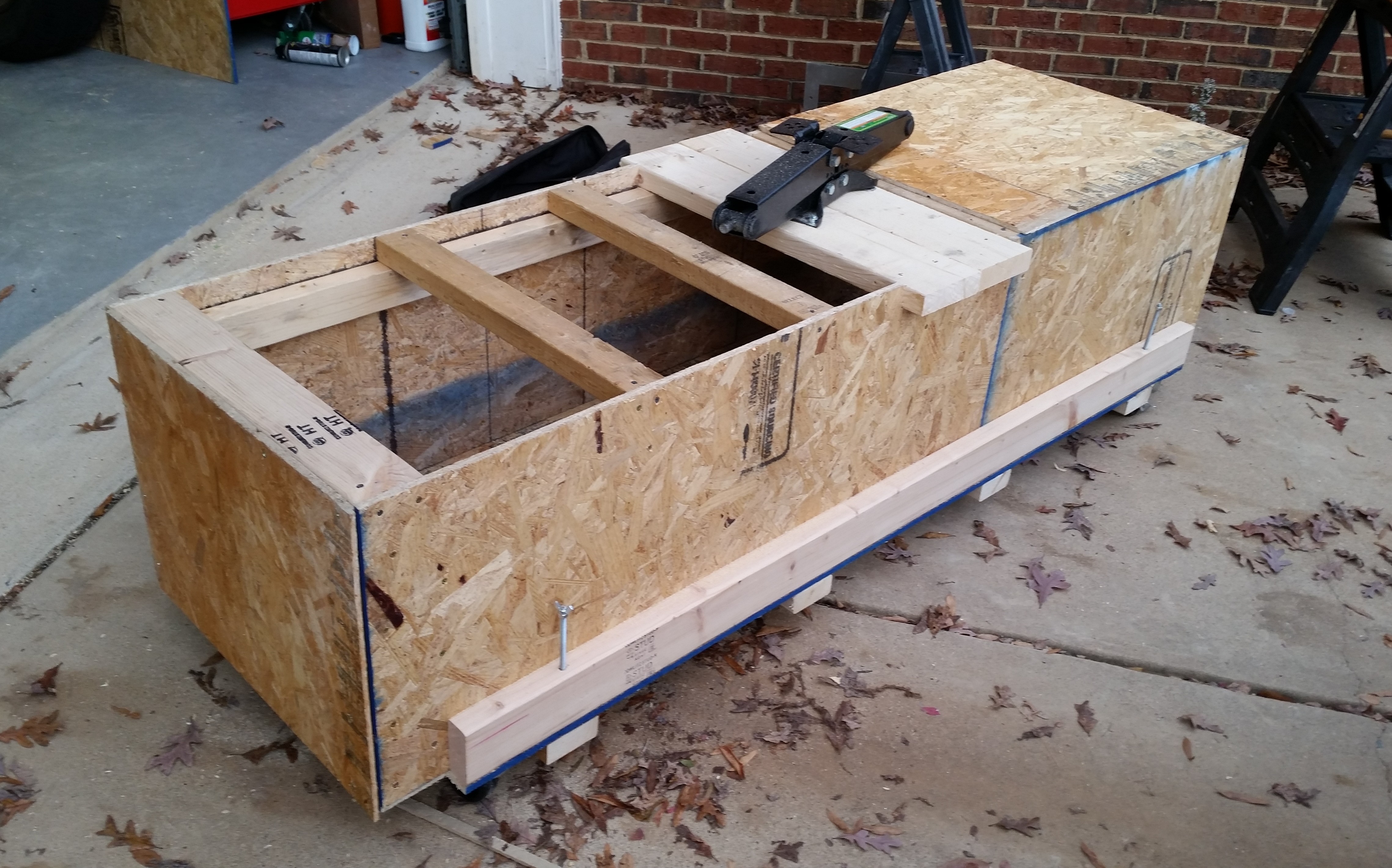
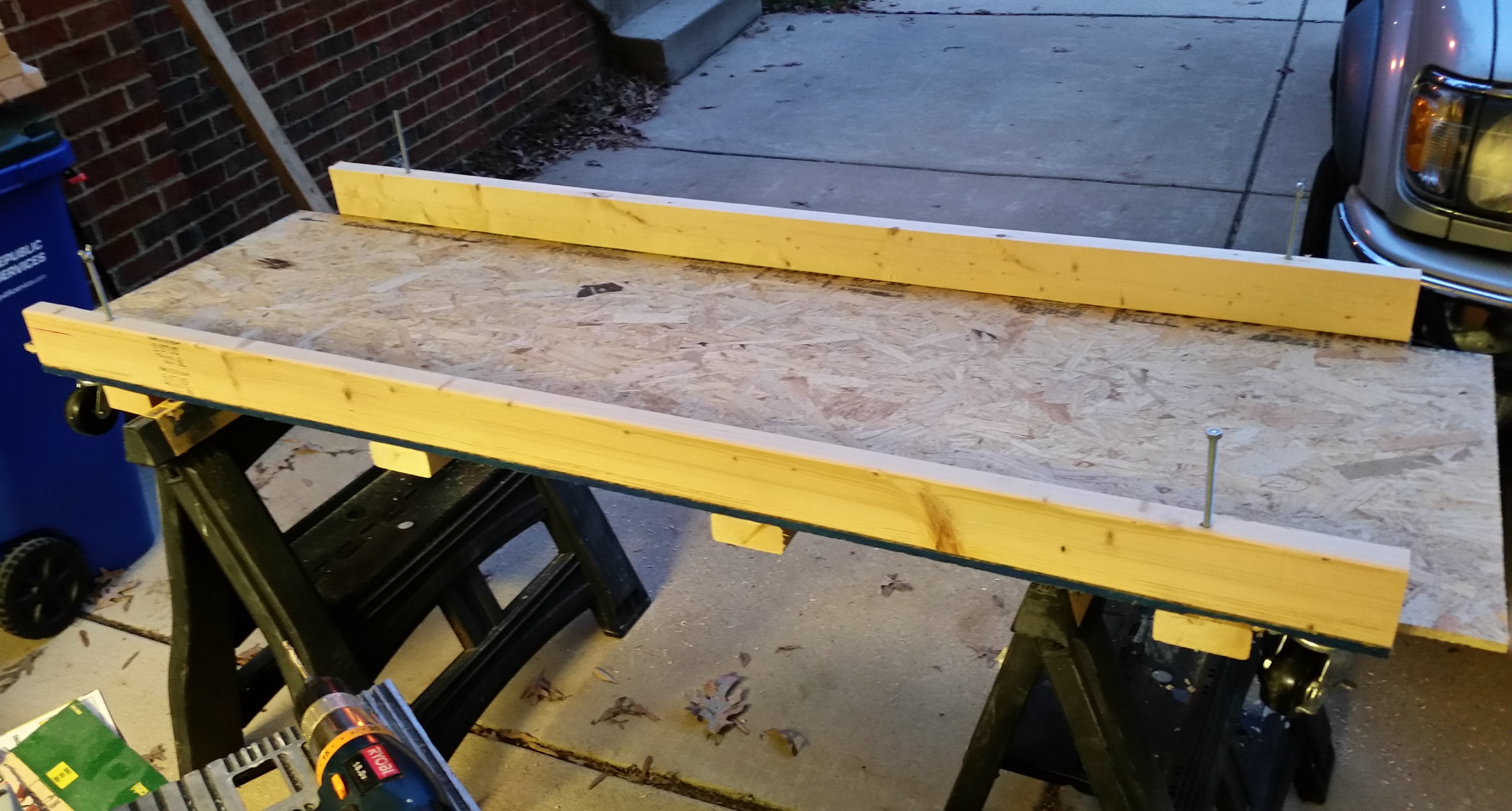
Here’s the stash of goodies that will turn into an operational fuselage dolly.

Fuselage Dolly

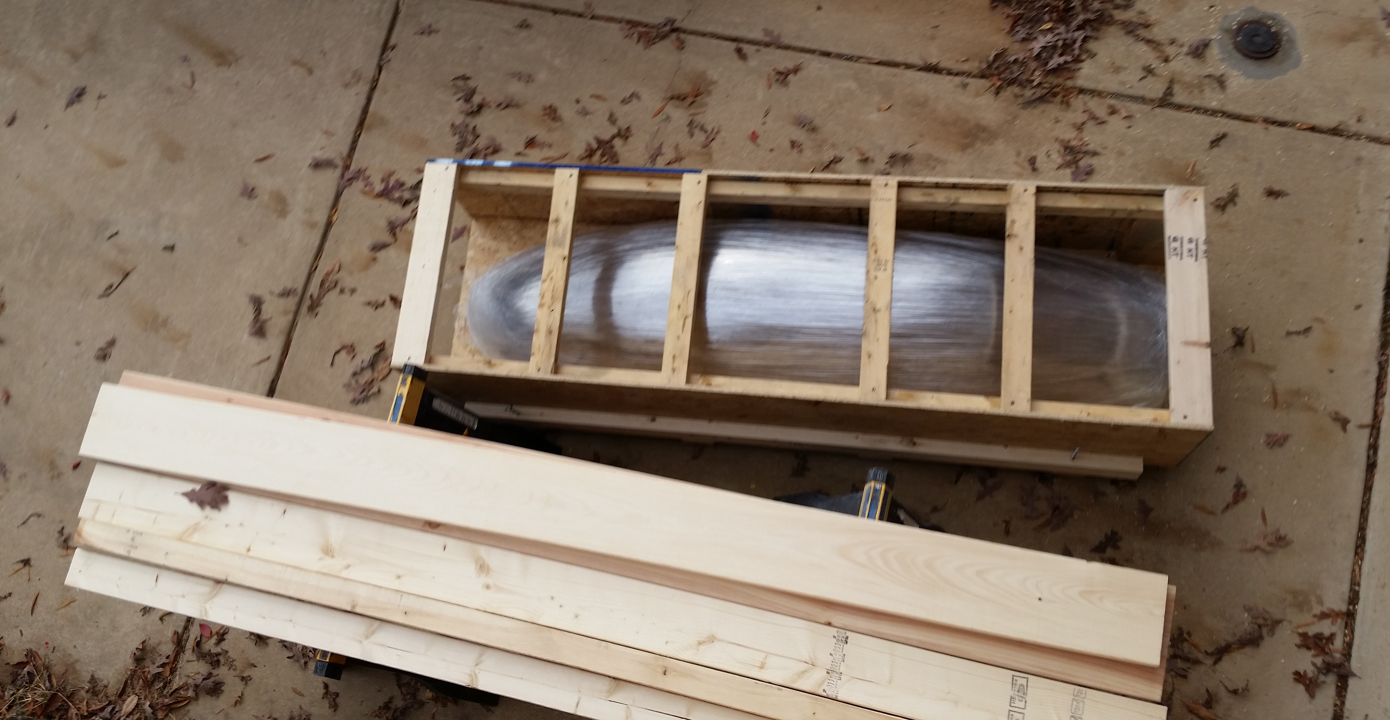
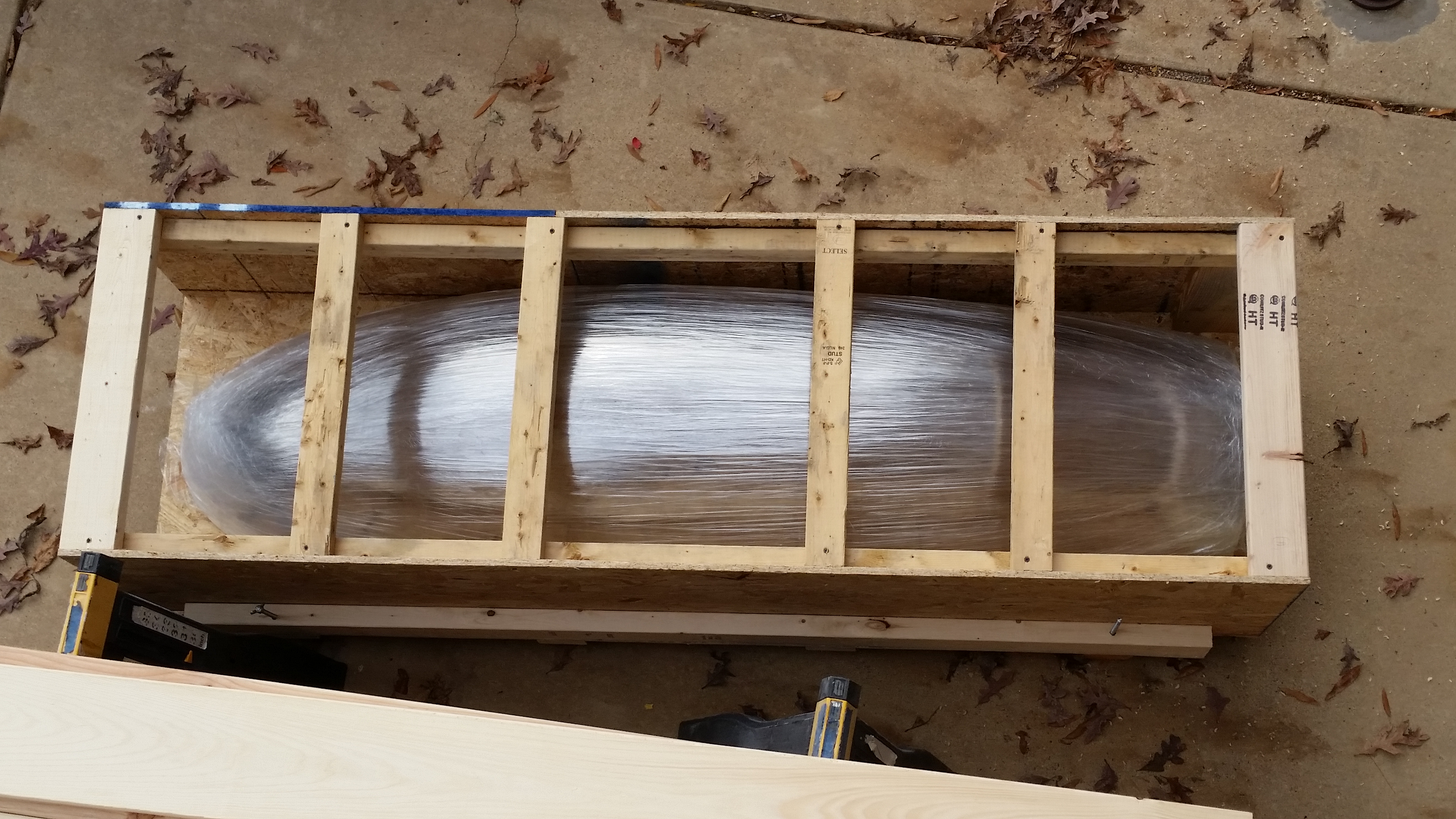
I pulled the canopy out and placed it into the fuselage dolly . . . it fit perfectly!

Testing Canopy fit in dollyCanopy fits!

I then notched the sides to make a mount for the . . . ???

(what could it be?!)

Notching sides for screwjack mount

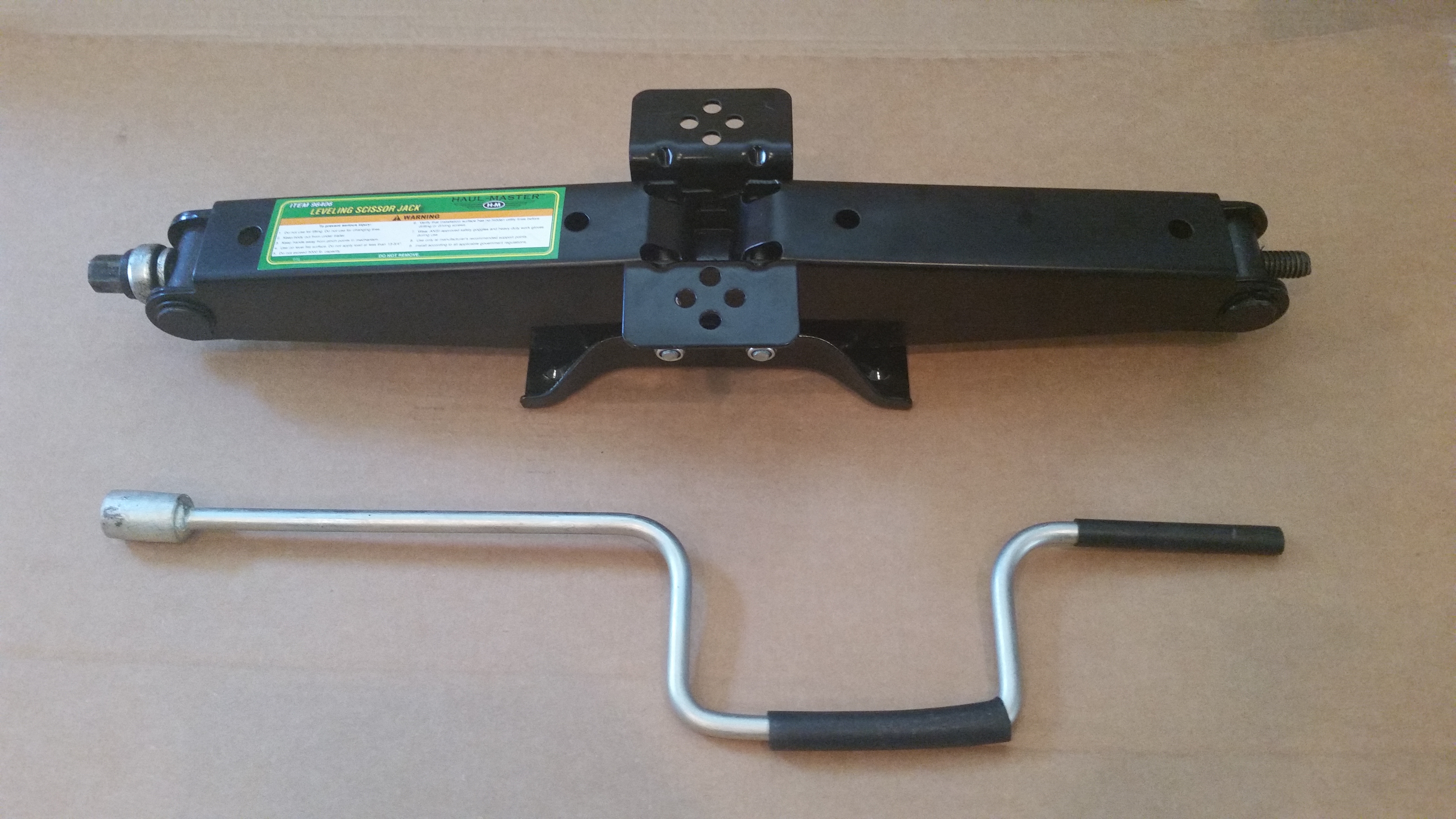
Yes, it’s a scissor jack from Harbor Freight!  At last, my secret is out!

As you can see in the pic below, I offset the jack slightly off center, a few inches towards one end of the dolly to allow the extension to meet the side near the front corner.  This will allow me to operate the scissor jack being off to one side of the centerline and not have to work with an airplane nose or tail in my face.

Screw jack placement

Here’s another shot of the scissor jack.  When extended the scissor jack gives me a good 19″ of added height.  I think you can see where I’m going with this, so I’ll have the base table height, and when need be I can raise the fuselage up from around 2′ off the floor to around 4′ up.

Harbor Freight Screwjack

Once I had the location figured out, I drilled the four 5/16″ holes for the carriage bolts.

Holes drilled in screwjack base

I then installed the carriage bolts.

Carriage bolts installed

After cutting the top two 2×6 pieces for the screw jack mount, I also cut & installed another 2×6 support in the front inside at each corner on one end (I had already installed these at the other end).

With the inside 2×6 supports mounted, I was then able to finish installing the final two lag screws for the wheels at the corner.

Finalizing wheel mounting

I then cut some shed siding that I had sitting around & mounted it in place.  I left one top side open to use when I clean out the lower fuselage dolly before placing the canopy inside of the box.  It will then be sealed completely (via wood siding) to protect it.

Below is the last shot I took of the fuselage dolly in its latest state before I packed it back up in the garage and quickly changed to get on the road to see my buddy Doug.

State of dolly, end day #2

My good friend Doug & I were Air Force Bomb Squad Technicians (Explosive Ordnance Disposal) stationed in England together back in the 1980’s.  It was great seeing him & catching up, and since he’s a pilot, we had some good conversations about a variety of Burt’s creations!

Old Bomb Squad Buddies!

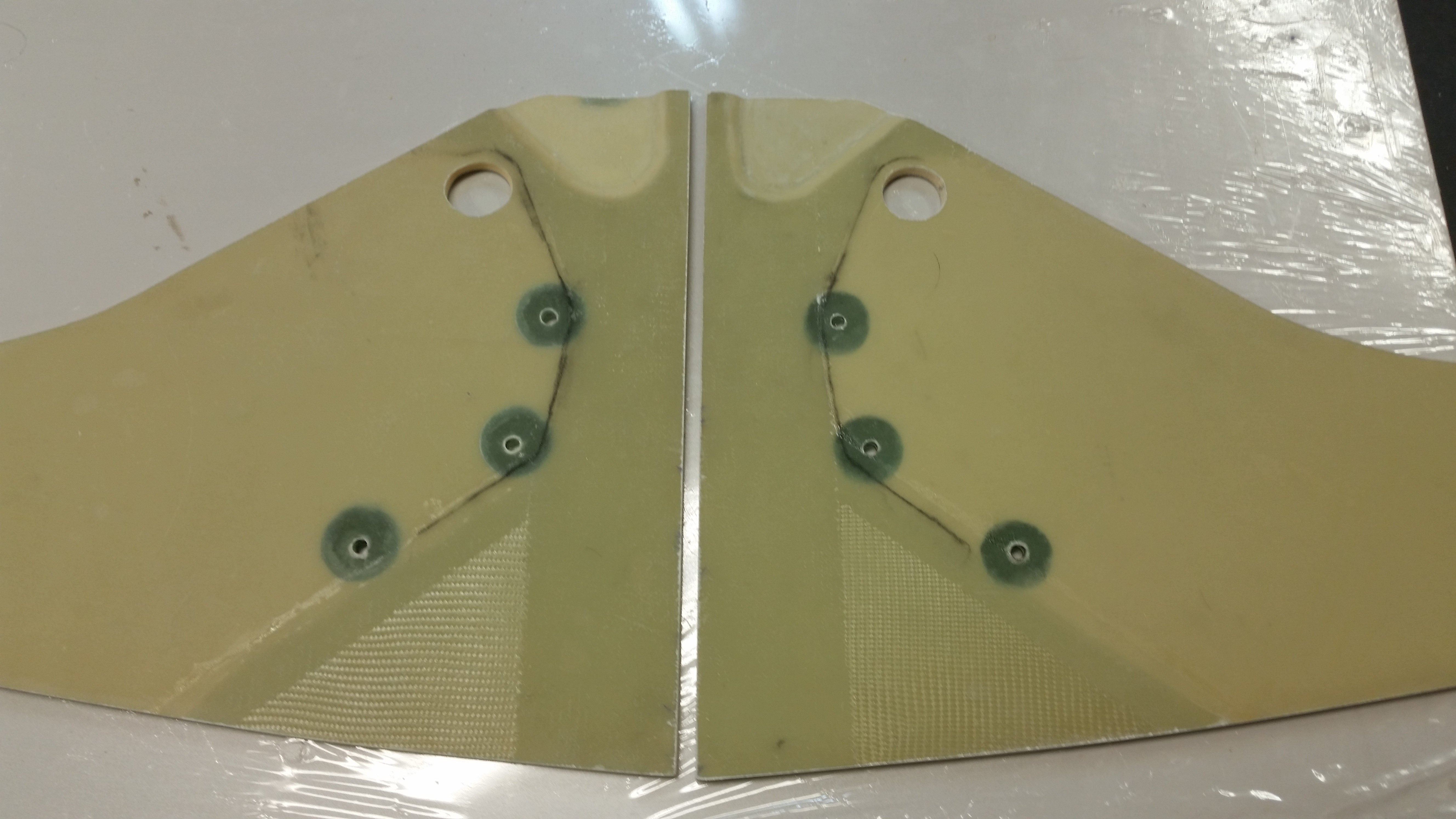
When I returned home after having dinner with Doug, I knife trimmed & sanded the edges of the NG30 layups from earlier.  I’m really happy with how they turned out & think that they will be very beneficial in their new state.

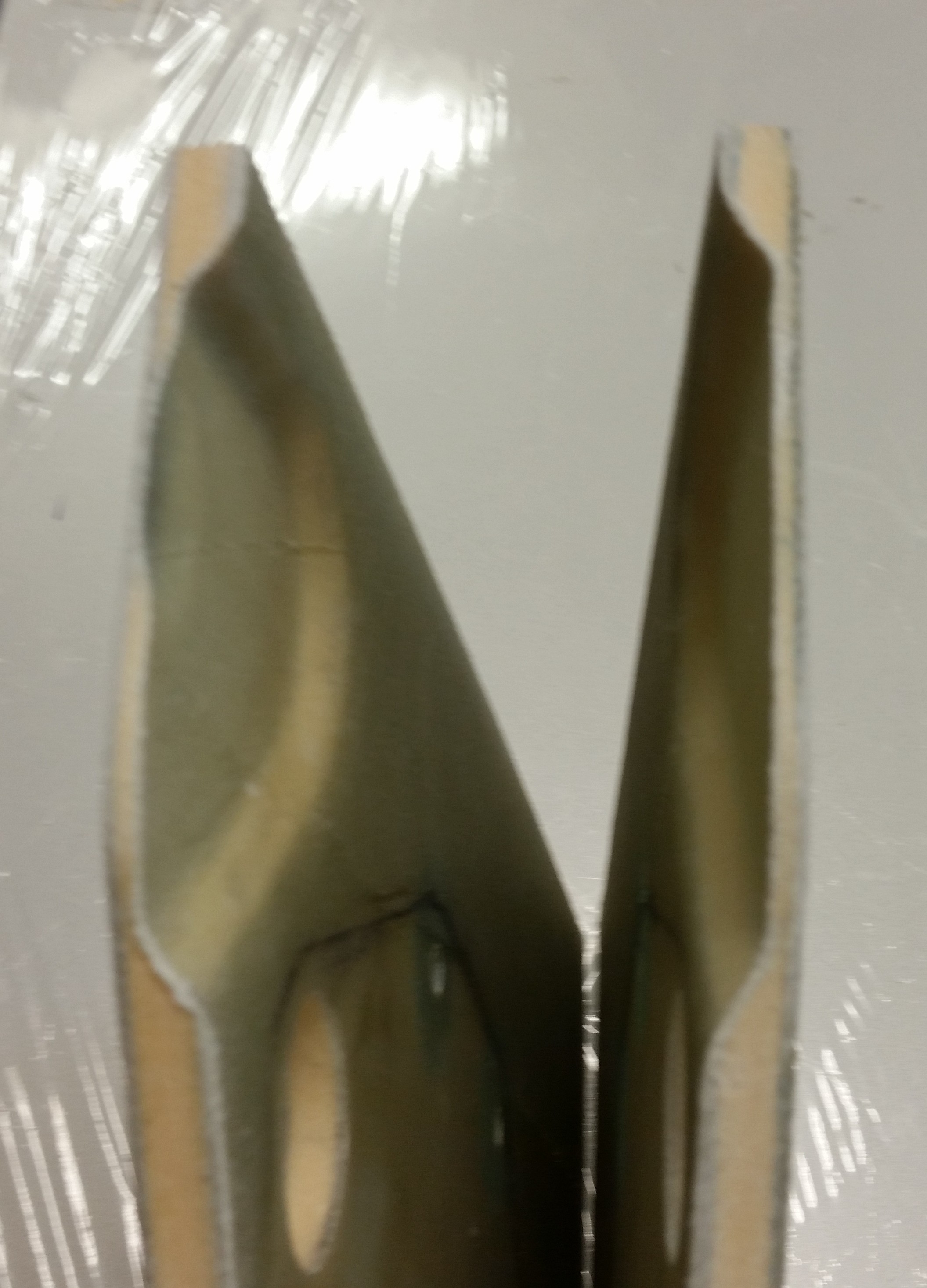
Final inboard NG30 layupTop view of NG30 depressions

Tomorrow I plan on working on the outboard sides of the NG30s (more layups), the fuselage dolly and canard.


No sanding today . . . sluffing off!

After my meeting at work today, I grabbed lunch on the way home and went over my plans for the dolly I will be building for the fuselage, ala my buddy Mike Beasley.  Since I was close to the final design, I knew that I would actually need to build the base to get enough data to finish this sucker.

First off, why am I doing this now?  (Instead of planting my butt in front of the canard and sanding away . . . ???).  Well, the reasons are: A) To take a break from sanding while still being incredibly productive!, and [more importantly] B) I don’t want to get to a point where I am so frustrated with positioning, repositioning & flipping the ever-weight-increasing fuselage that I work in a less optimized state until then, and then have to take time out to build this thing.  Also, with my buddy’s fuselage incident where it fell off the saw horses & smashed his rear longerons, I figured I would pay the piper up front and get this fuselage dolly knocked out early so I can enjoy its functionality.

Here are the key features and requirements for this thing:

  • Had to be mobile (i.e. on wheels)
  • Had to be low enough when working IN the fuselage & high enough when working ON the external fuselage (adjustable height . . .  more to follow!)
  • Had be able to be leveled as a surface–not shimming the actual item, but leveling the platform itself. (Leveling screws . . . aka, poor man’s outriggers)
  • Secure canopy storage (since I would have the length and width, I might as well make the underneath area useful and store the canopy in a wood box)
  • Optimized stabilization of the fuselage (when the fuselage gets its nose, etc. more weight will be added and more awkwardness in controlling it will ensue, thus multiple tie down points are a must)

So, while sitting having lunch 2 blocks from Lowe’s, I realized that I had met all my critical design goals and I could begin construction immediately.  I bought a couple of sheets of flooring material (OSB) and a few 2x4s to get me started.  While checking out the cashier asked me if it started raining yet!  So with that info in hand I rushed to get to the house and get some wood cut.  It did sprinkle on me quite a bit, but never got into an actual downpour, thank goodness.

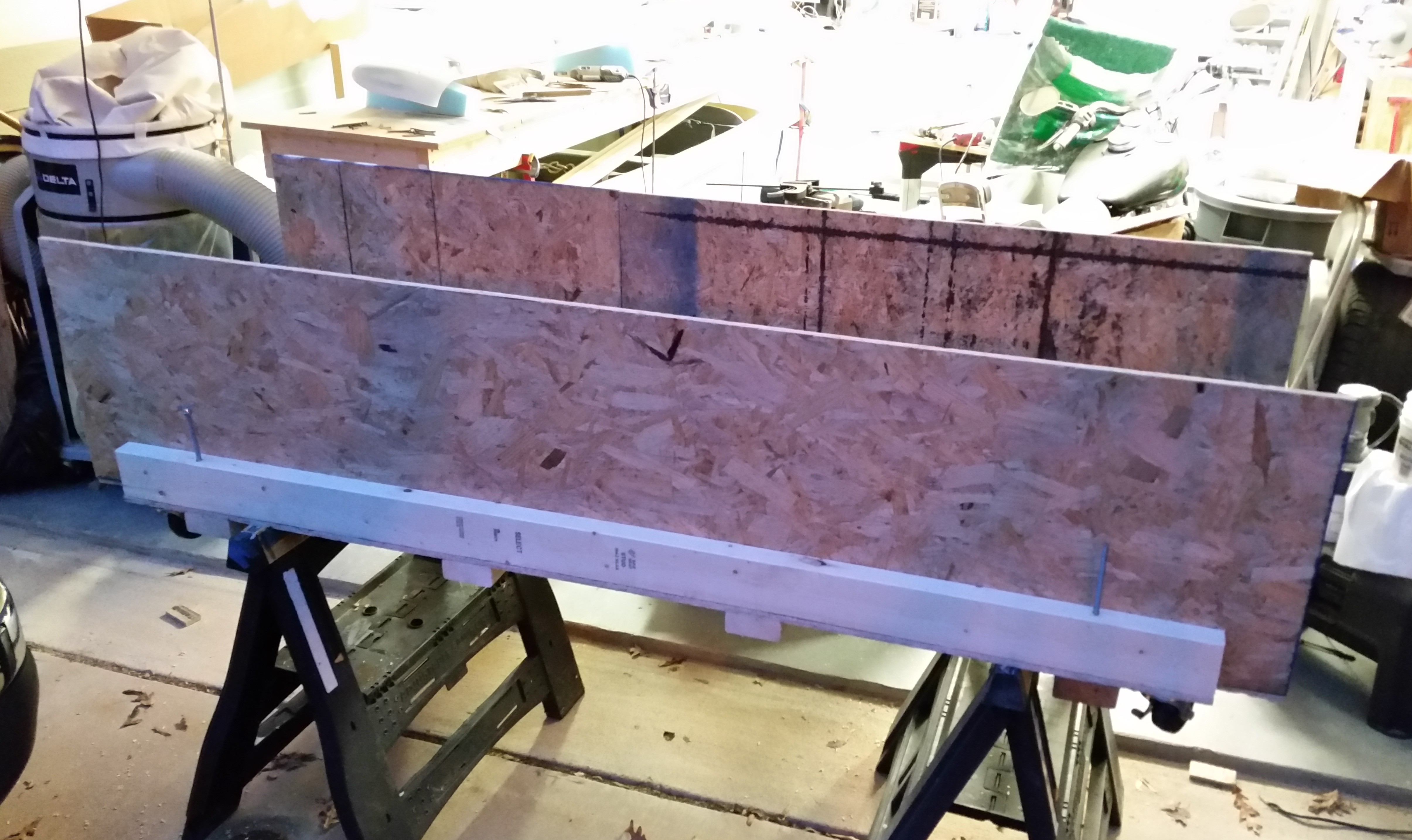
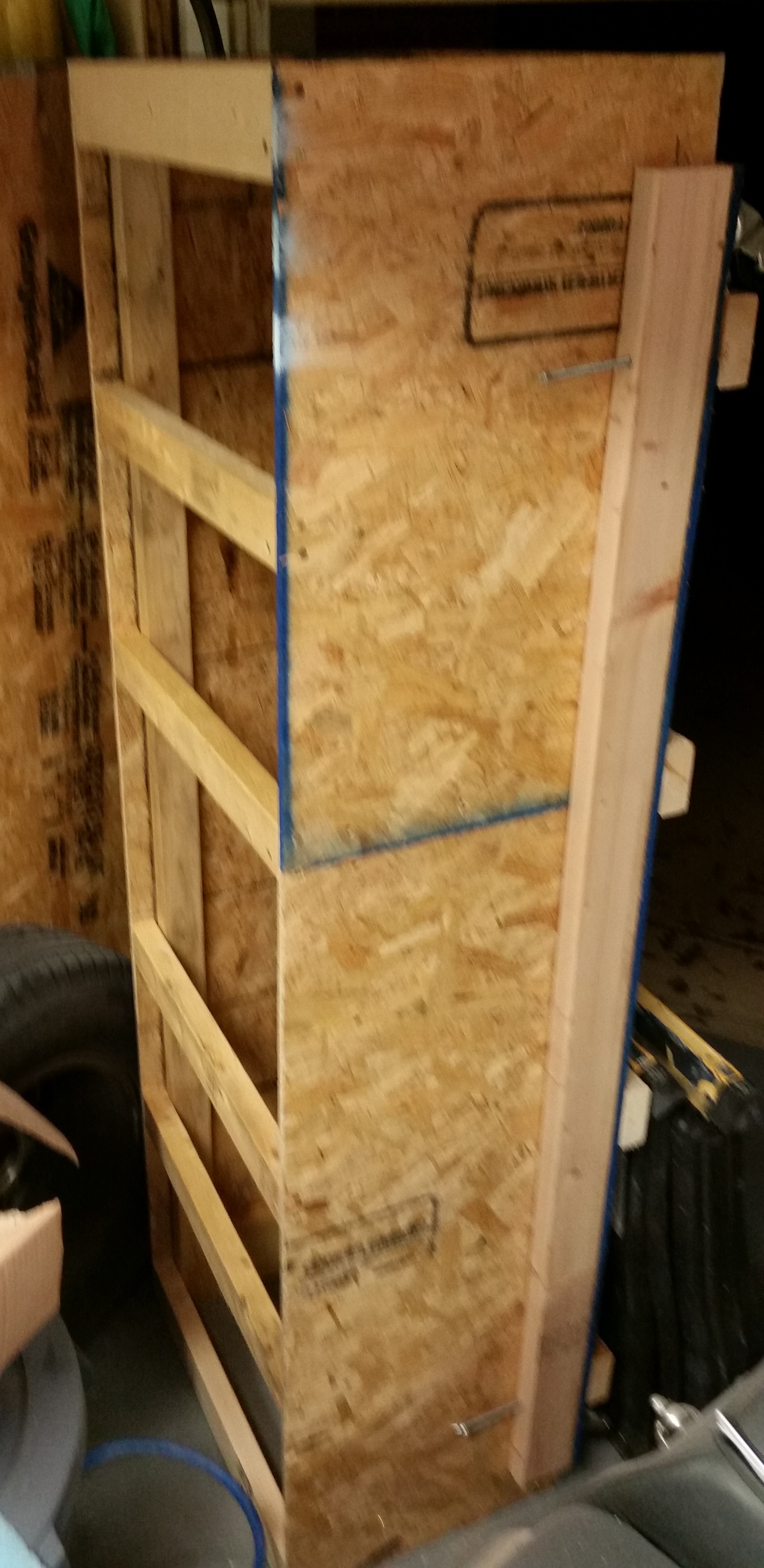
After cutting the wood, I started constructing the base of the fuselage dolly.  Here’s the very bottom of the dolly.  I’m about to attach 4 each 2×4 cross beams & the wheels to the bottom of this thing.

Bottom of fuselage dolly base

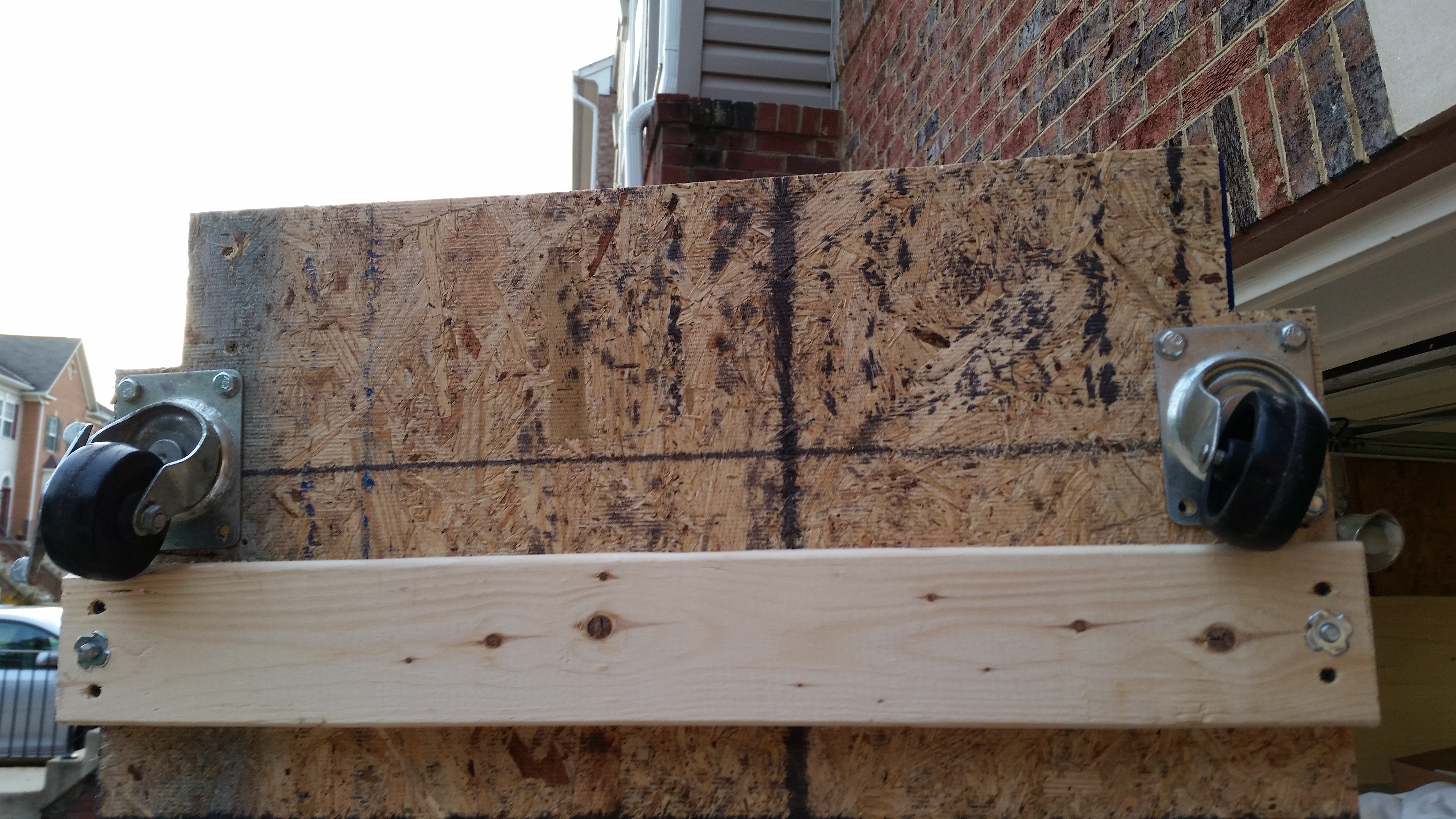
Here’s the base turned upright.  If you look closely you can see the wheels near the corners (mobile) and the four threaded leveling screws just inboard of each corner as well.
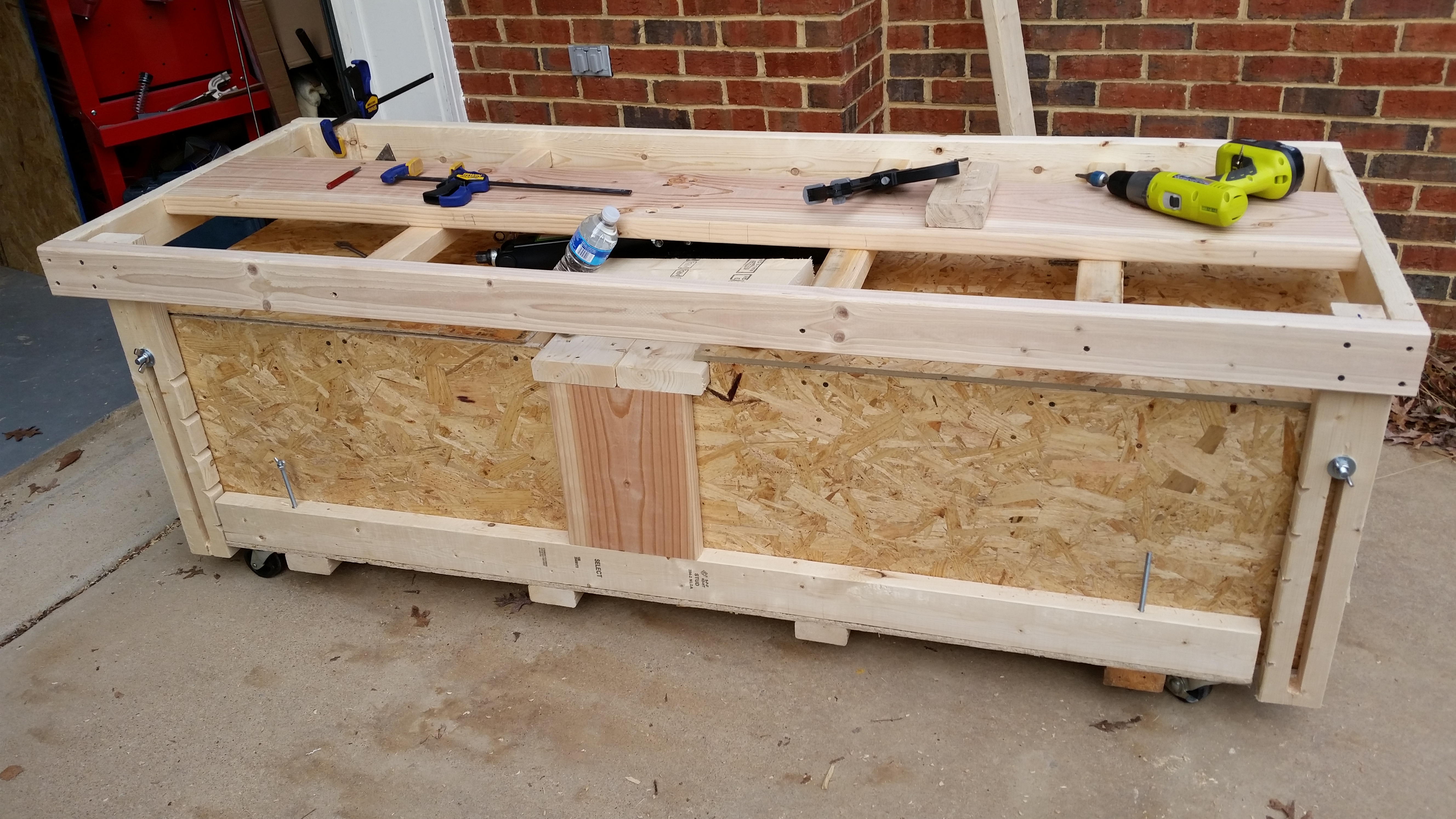
Top of fuselage dolly base

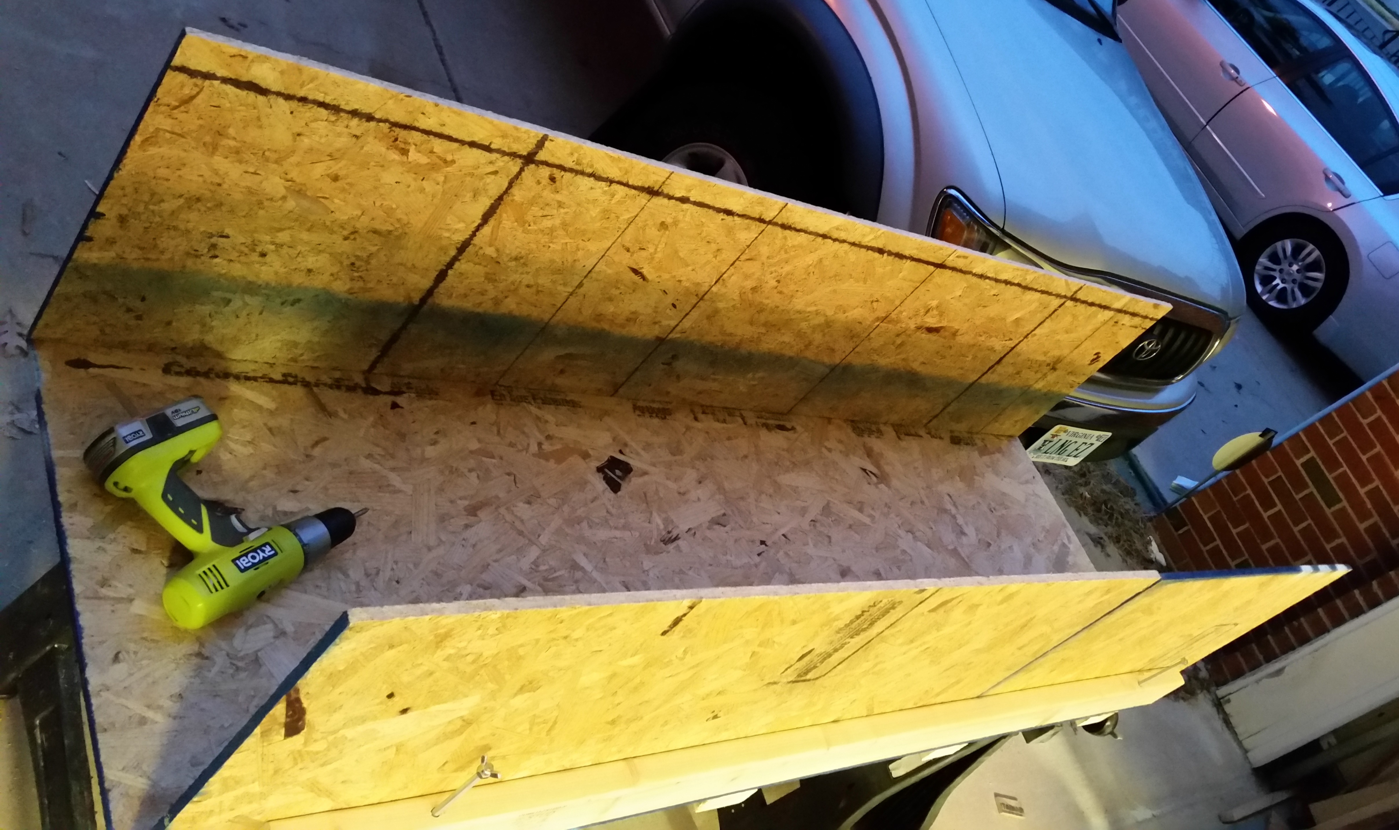
Here are the OSB sides attached.
Side walls added to fuselage dolly

And the future temporary home of the canopy.
Canopy storage area

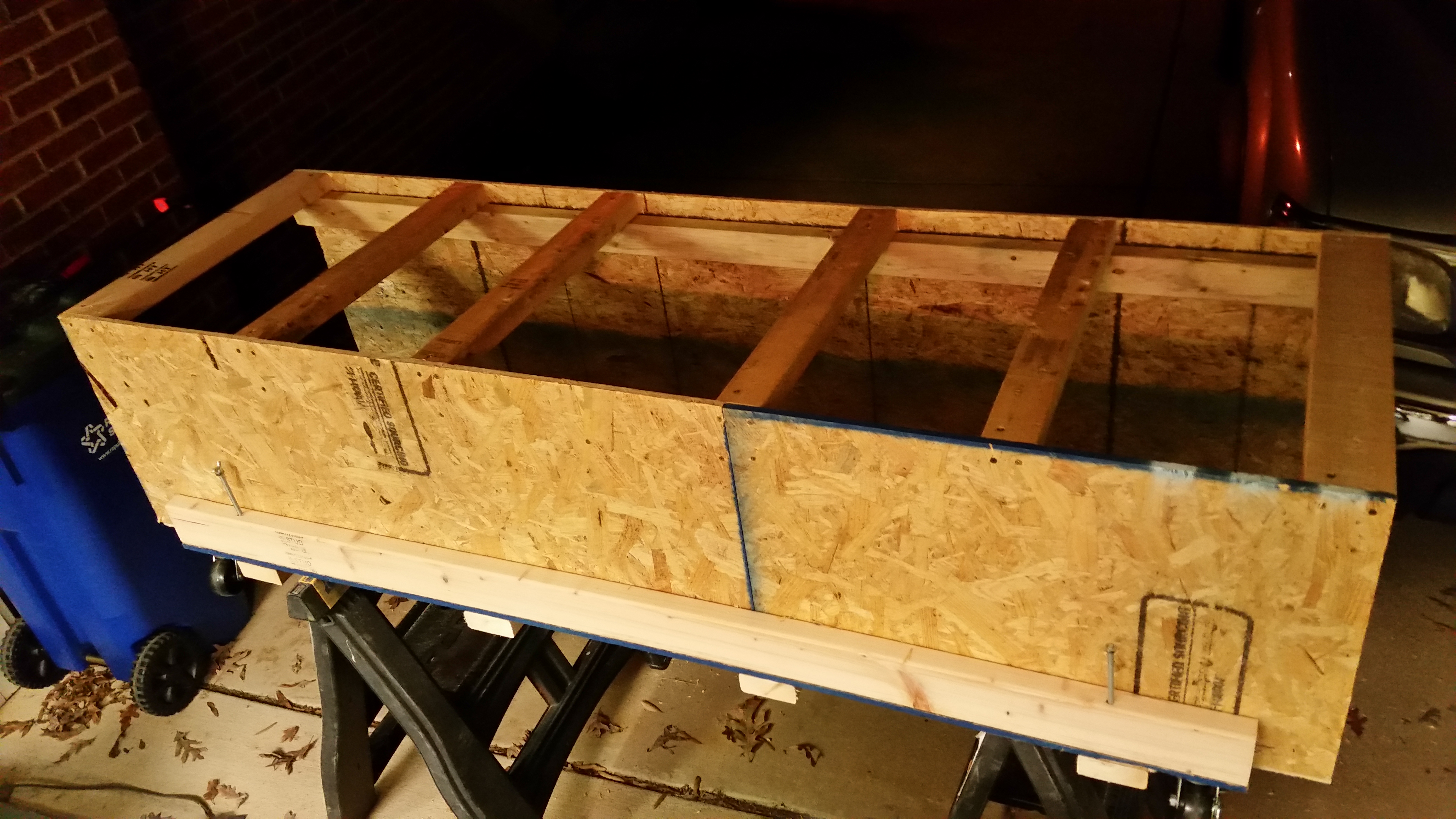
I added the top cross joists that sit on a 2×3 stringer that runs the whole length of the dolly on each side.

Top cross beams - fuselage dolly

After getting to the point where I needed to cut more wood, and for some parts buy the wood to cut it, and get some more hardware, I cleaned up my work area and stowed my new creation up on end.

Temp storage of fuselage dolly

I then ran off to Harbor Freight to pick up some “supplies” . . . mission operational security does not allow me to divulge any information until later, after it’s been implemented and tested.  ha!

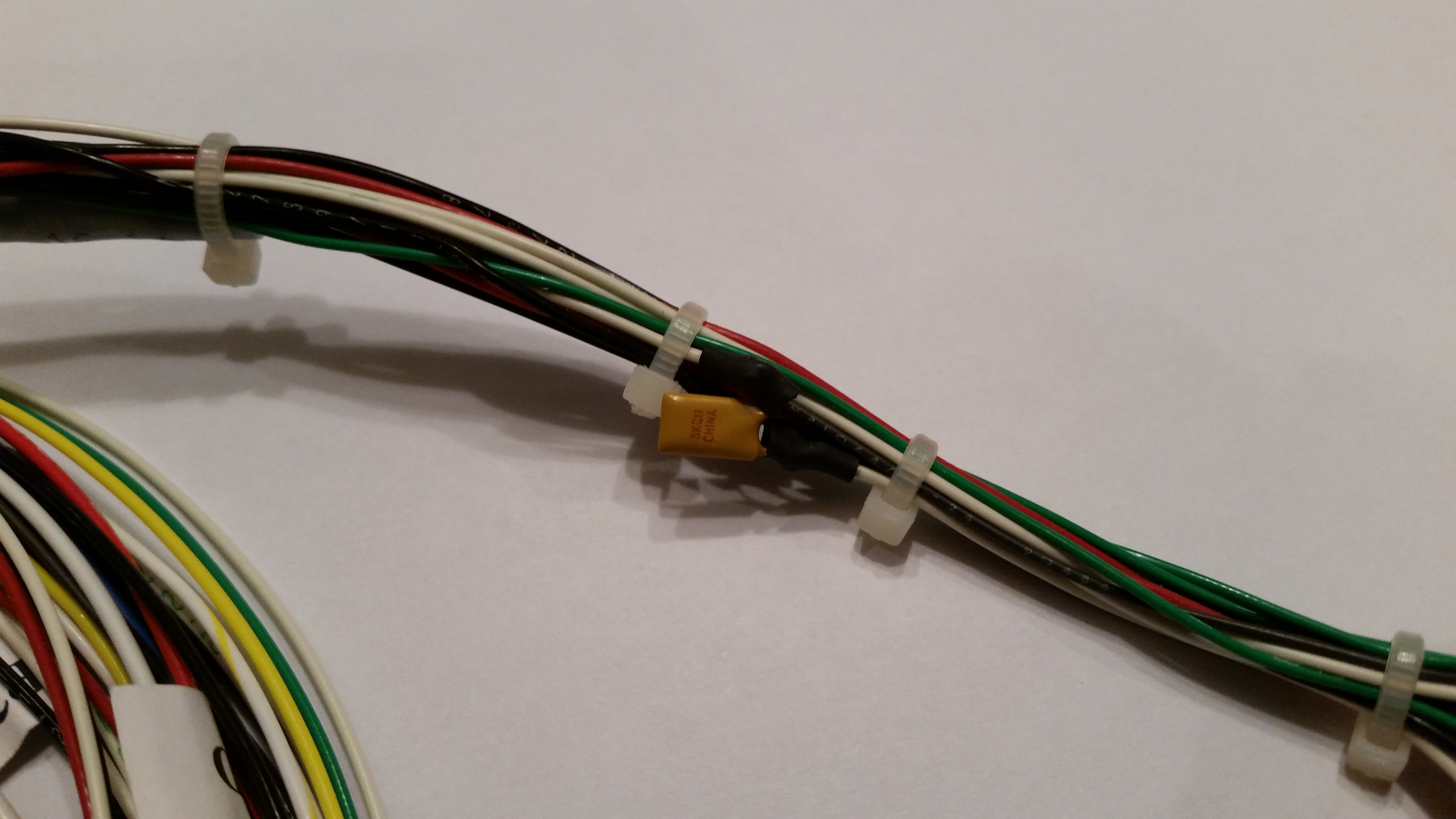
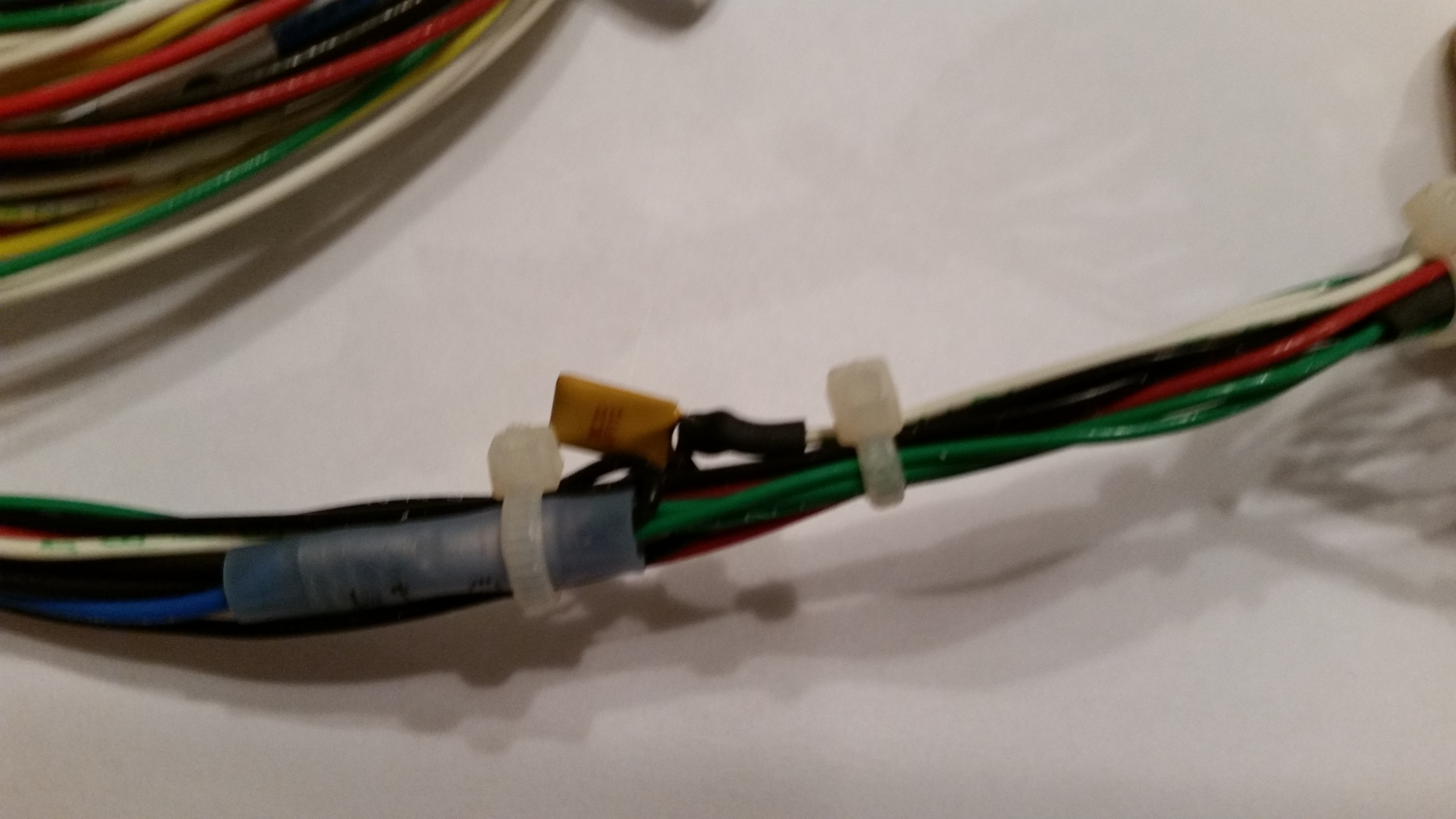
Upon returning home I sat down to fix a design flaw in the Nose Gear Actuator wiring before it became a problem.  There is a small electrical component (diode? capacitor?) that was soldered in the wiring line with one of its two tiny legs soldered to a wire on each side.  If you look at the second pic you can see daylight between the component and the wiring bundle.

Now, my Long-EZ building buddy, Capt Meatballs, pointed this out to me after his broke and he had to find it via troubleshooting.  The connection legs were so fine, that when the one side broke he had to buy an entire new component & solder back into place to fix it.

Electric gear actuator preventive maintenance

Potential for mechanical failure

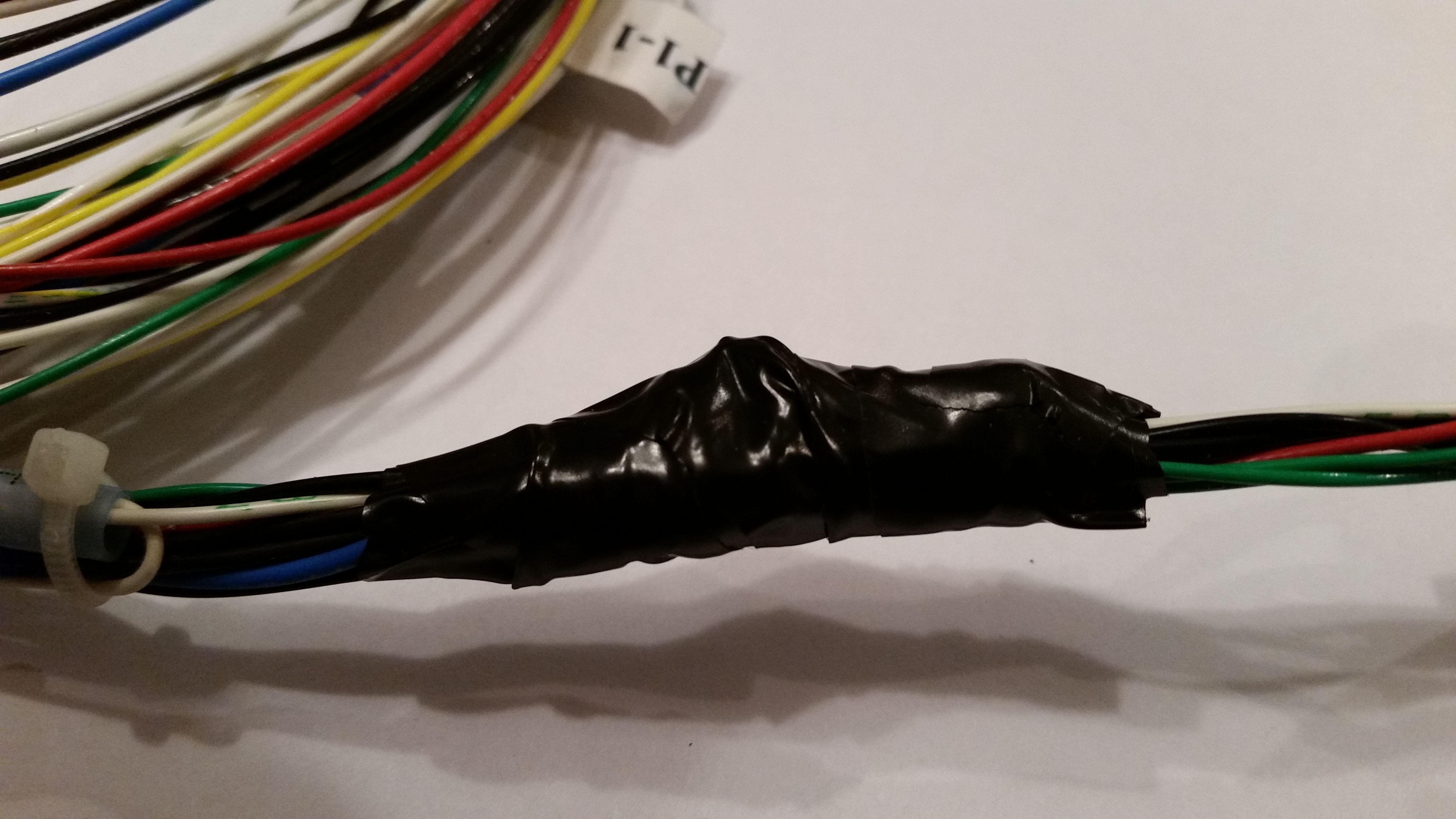
To avoid this issue I employed the “poor man’s electrical potting material” solution to this situation.  I took electrical tape that I had folded over a couple of times and wedged it underneath the suspended wire legs on each side to secure them from any pressure coming through the tape and still snapping off one or both of the legs.  I then wrapped the whole assembly in electrical tape.  May not be the prettiest fix, but with a big clump of relays just down the line I wasn’t able to get some tubing shrink wrap over it.  So this fix will have to suffice!

Poor man's potting material!Poor man's potting material!

Now that I have the base of the fuselage dolly built, I’ll start incorporating it into the build schedule.  Thus, while any part, epoxy, or primer is curing I’ll take a few moments to get this dolly built.  My plan is that when I start in seriously on the nose & nose gear that I’ll have this fuselage dolly underneath the fuselage and ready to go.


Chapter 10 is Complete!

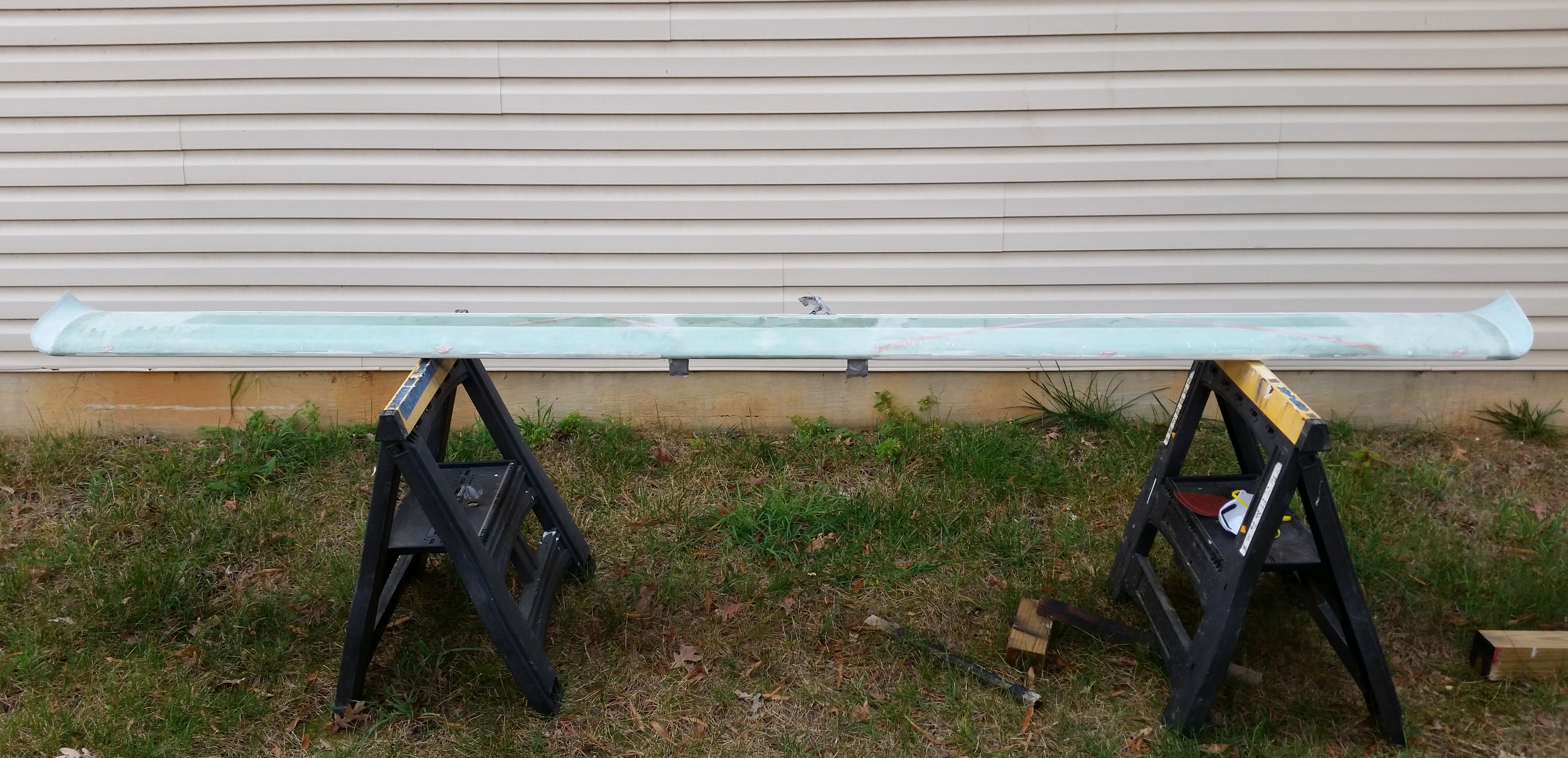
Yes, my dear friends, I’m calling the canard complete!

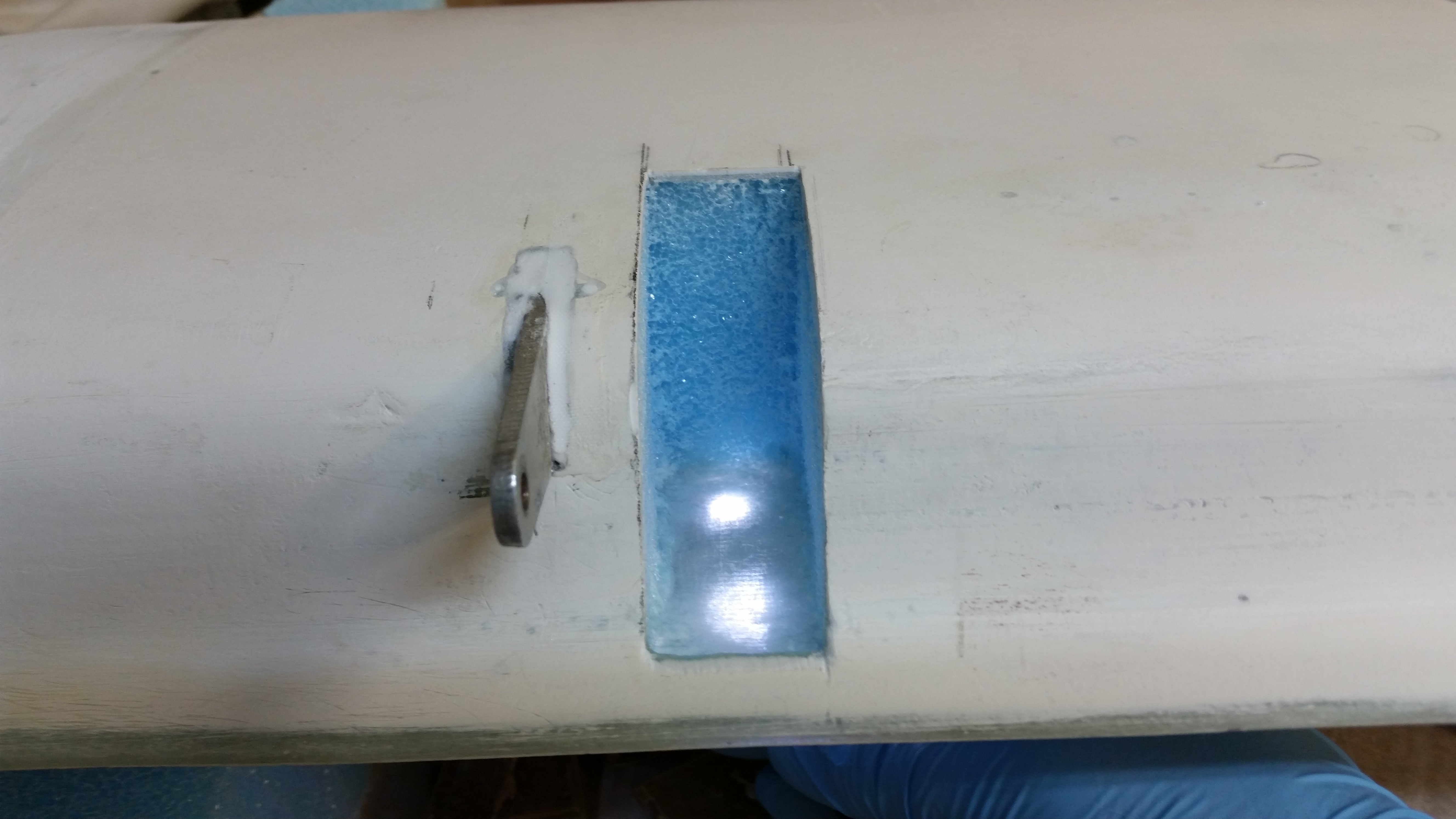
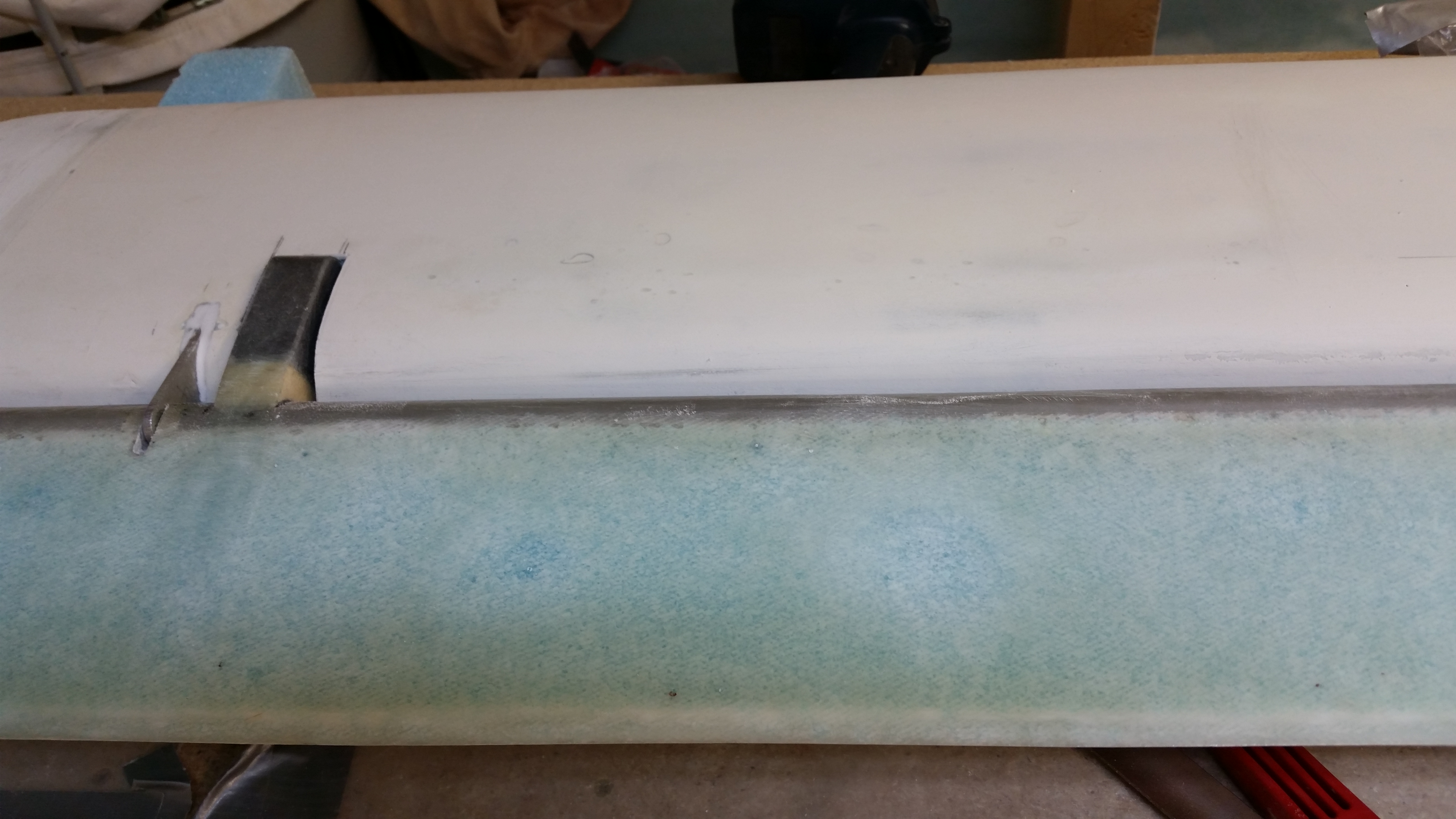
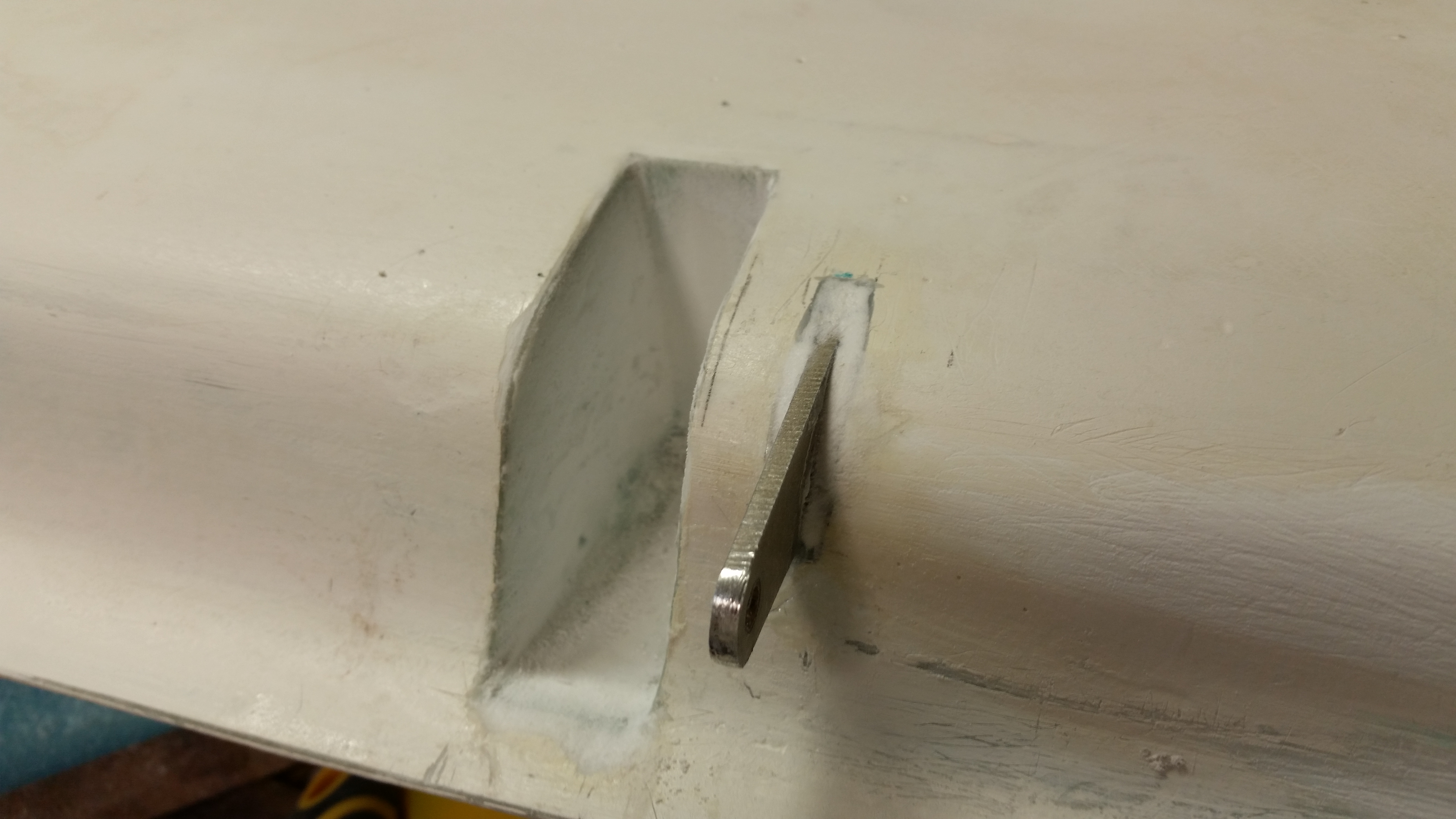
I started off today by cutting out the right elevator weight notch in the canard.

Elevator weight notchElevator weight notchElevator weight notchElevator weight notch

Here I’m checking the opacity of the glass beneath  . . . ha!

Checking glass opacity . . . ha!

I measured everything out using the right elevator as a template and then got to work on micro’ing the sides and laying up 1-ply of BID to protect the foam.

Using "bad"elevator for template

BTW, here’s the left side still in the same state I left it in after last night’s cheese grating.

Elevator weight notch cheese grated

And here are the smaller bits ‘n pieces after I hit them with some 80 grit.

Fine sanded stuff!

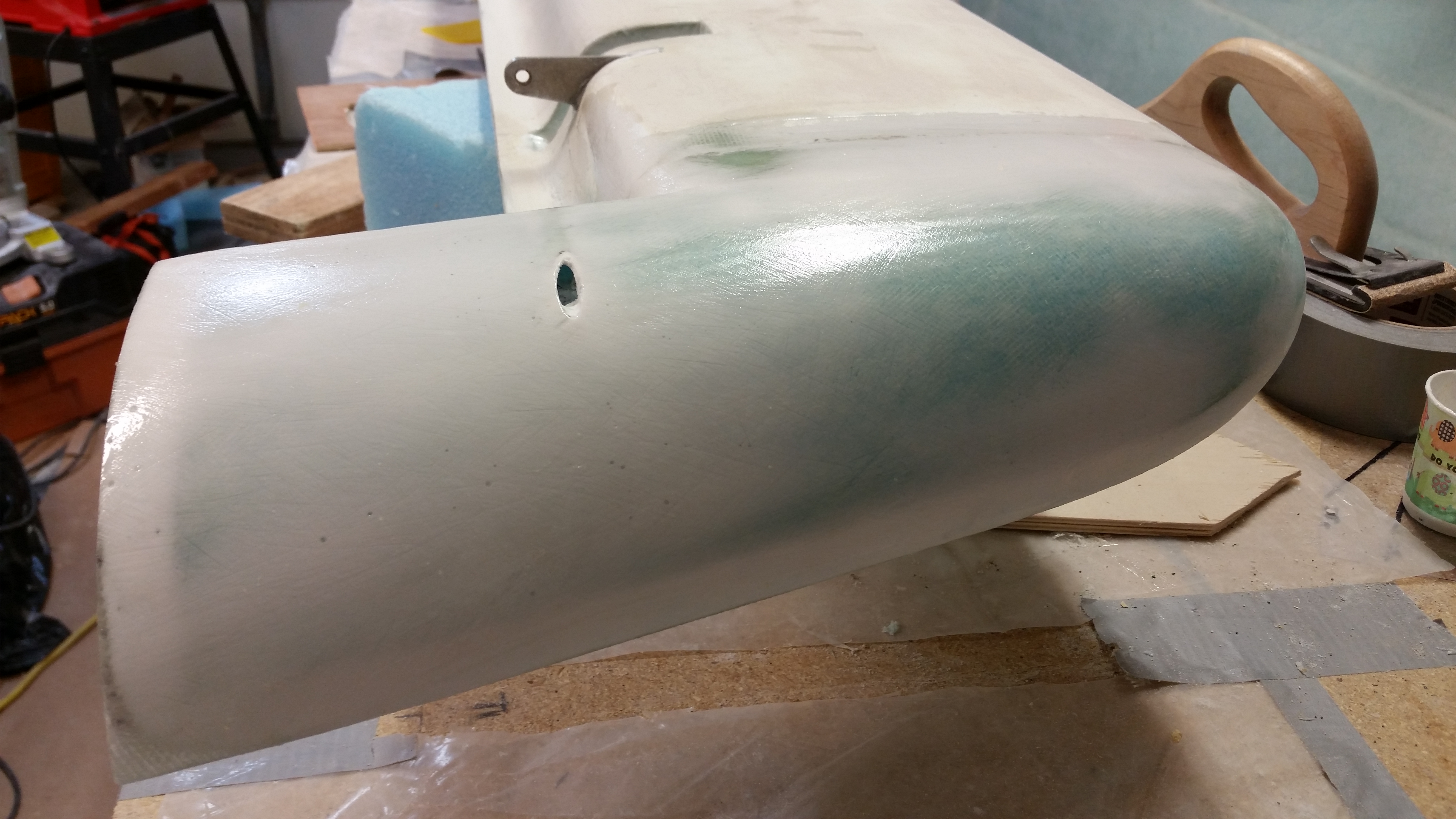
After I got the weight notch sorted out, I mixed up some West epoxy and started applying epoxy swipes to the remaining parts of the bottom of the canard that weren’t finished (swoosh tips, swoosh tip inboard rib, weight notches, etc.).

Pure epoxy wipes

Here’s a shot of the right inboard swoosh tip area after a couple of coats of epoxy.  And a shot of the glassed right elevator notch with 1-ply BID.

Right weight notch glassed

Below is a shot about 9 hours after the one above, and the tips are covered with 5 coats of epoxy.  I’lll let it cure overnight and sand it tomorrow.

5 coats of epoxy!

On with the nose gear!

I measured everything out with the sidewall brackets that sit internal to the NG30 plates and hold up the electric gear actuator.

Drilling top NG30 holeDrilling top NG30 hole

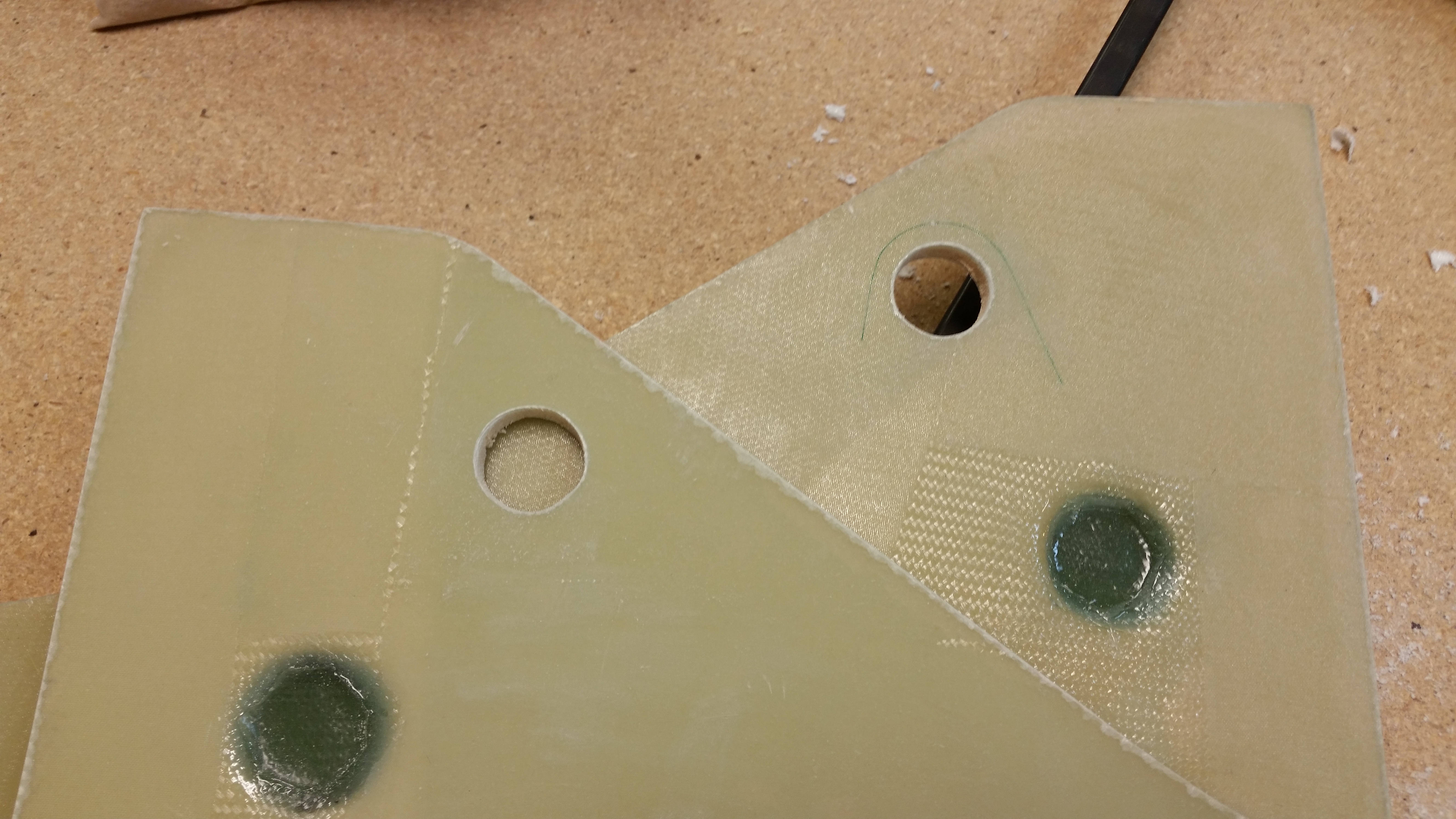
Unfortunately my zeal got the best of me.  After checking something in the gear actuator install instructions I ran across a statement where the holes in the brackets (not shown) need to be 3/8″ away from the side of the bracket at the center of each hole.  Mine were set at a 1/4″ away from edge to hole’s center.  This changed the angle required to get the holes drilled correctly for the brackets.  Not a huge a deal, I’ll just have to widen that top hole a bit aft.

Drilling top NG30 holeTop NG30 holes drilled

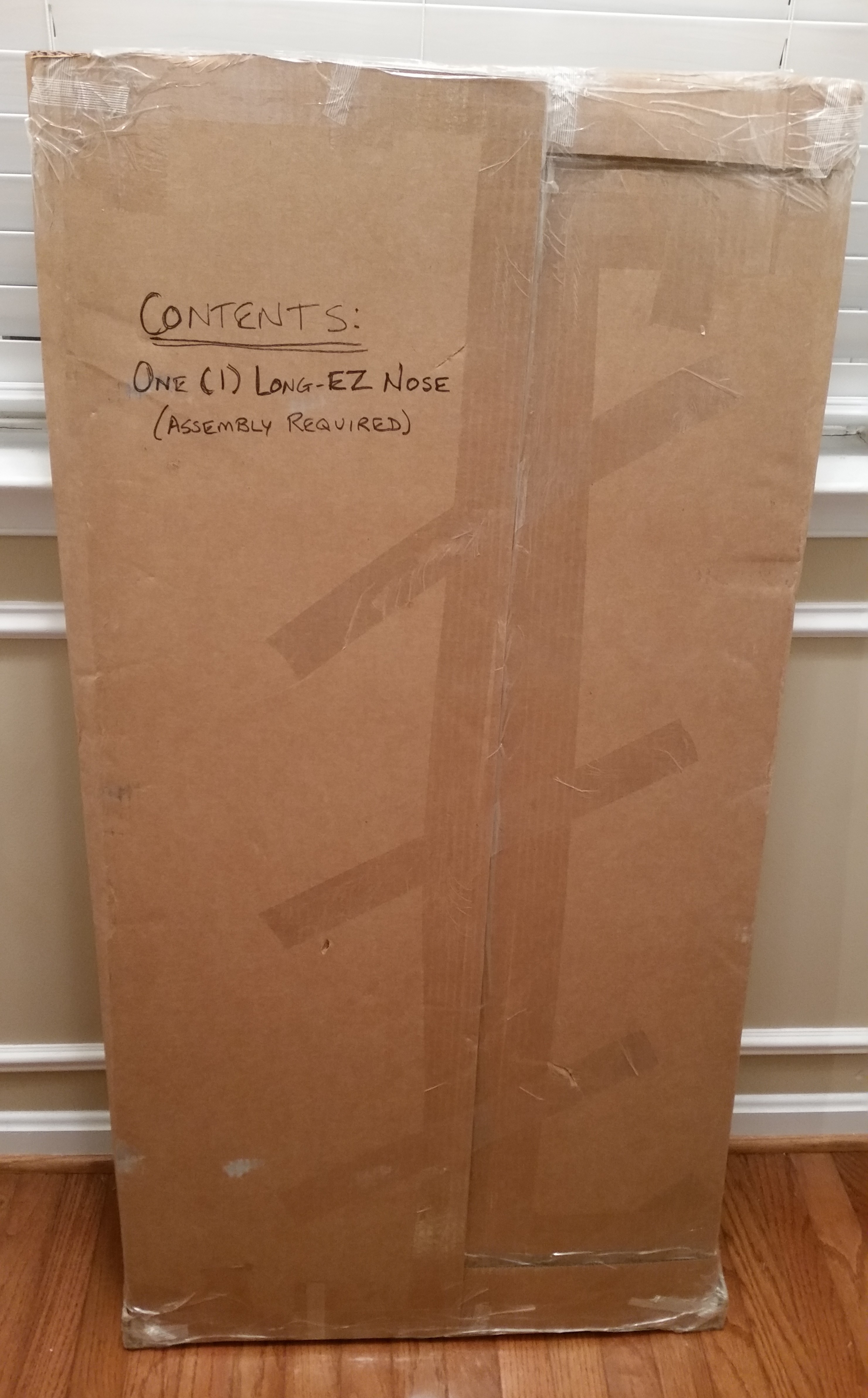
Oh, and speaking of NG30’s and stuff, look what just came in the mail:  my nose!  Says on the box that some assembly is required!  Haha!

Yeah! The nose came! Ha!

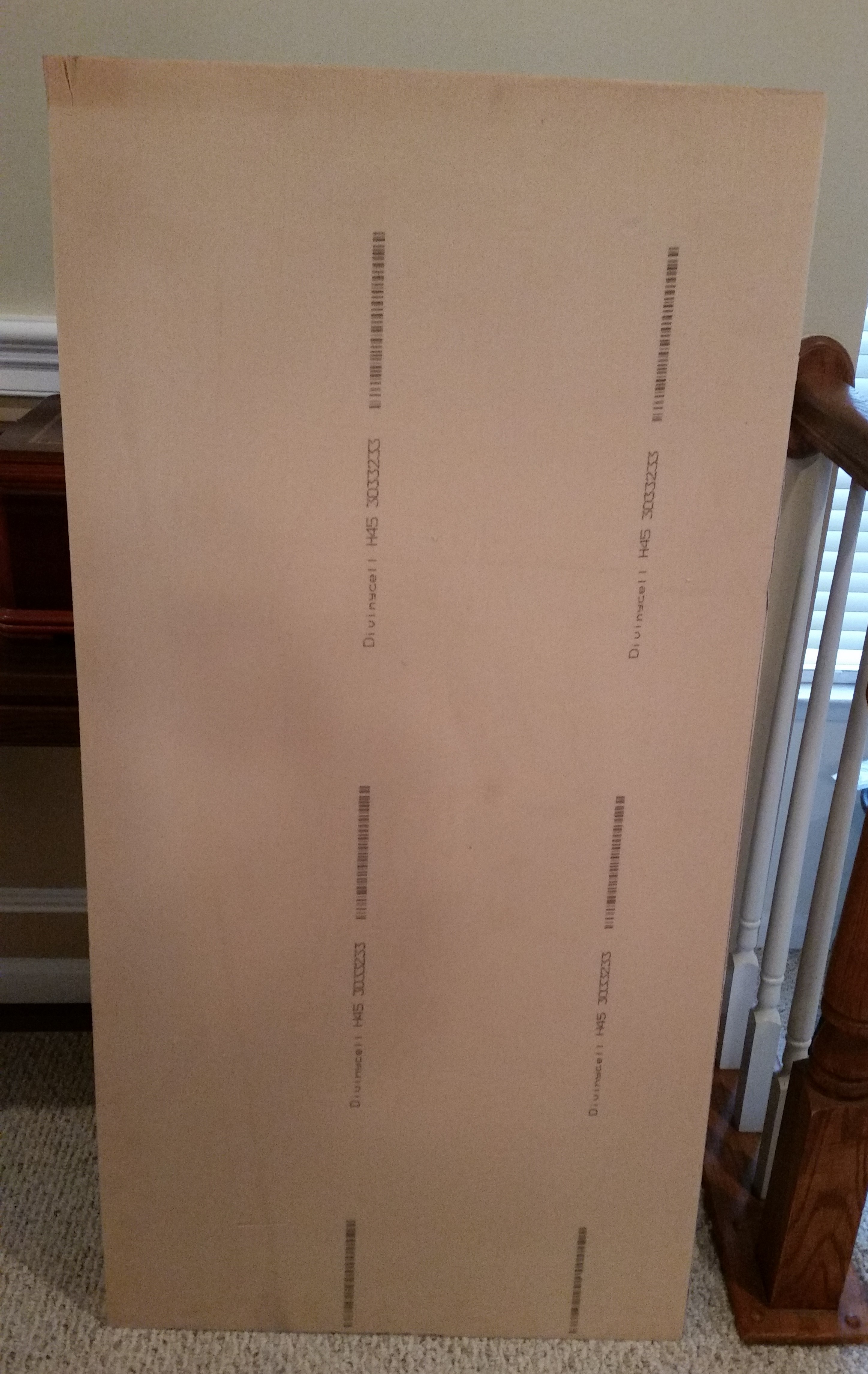
Interestingly, I was just having a conversation the other day with a good builder buddy of mine talking about how some builders have yellow foam in their build that isn’t polyurethane, but actually Divinycell (H45).  Well, guess what?  My “blue” Divinycell foam showed up yellow.  I mean, I asked ACS if they could send me the lightest Divinycell possible . . . but I was talking WEIGHT, not COLOR!  ha!

Yellow Divinycell? Who knew?!

Chapter 10 & 25 – A New Itch!

Seriously, I did a ton of sanding on the canard today to prep it for finish, and yeah, I got the itch!

I set up my gear & took the canard outside to sand that sucker!

Now, I will say that before I actually started sanding the canard, I spent about 2 hours  researching & documenting the nose install & nose wheel mounting .

Sanding Canard for finishSanding Canard for finish

Below is a pic of how much of a mess I made by sanding the top of the canard. The pic below shows it all clean & ready to got back into the shop.

Sanding Canard for finishCanard sanded for finish

Once back in the shop I whipped up a fresh batch of micro finish using West epoxy to apply to the bottom surface of the canard.  I’m starting back on the bottom side to blend in the newly added canard “swoosh” tips.

Micro finish applied to swoosh tipMicro finish applied to swoosh tip

Here’s the shots of the inside rib of each swoosh tip:

Micro finish applied to swoosh tipMicro finish applied to swoosh tip

Since I had time & micro finish on my hands after swabbing down the swoosh tips, I heated up the cup and applied the micro finish to the ice shields.

Micro finish applied to Ice Shields

A few hours later after the micro “greened” I cheese grated it.  All I have to say is Wow!  Since I waited about another 45 minutes from normal time (2-3 hours vs my 3.5-4 hours… obviously YMMV) to cheese grate this thing, it worked like a champ.  As you can see I got all the major bumps & grooves sanded out on these added canard tips.

Swoosh tip cheese grated

Swoosh tip cheese grated

And again, here’s the inside “swoosh” tip rib that also got micro’d & then cheese grated (both sides):

Inboard swoosh tip cheese gratedInboard swoosh tip cheese grated

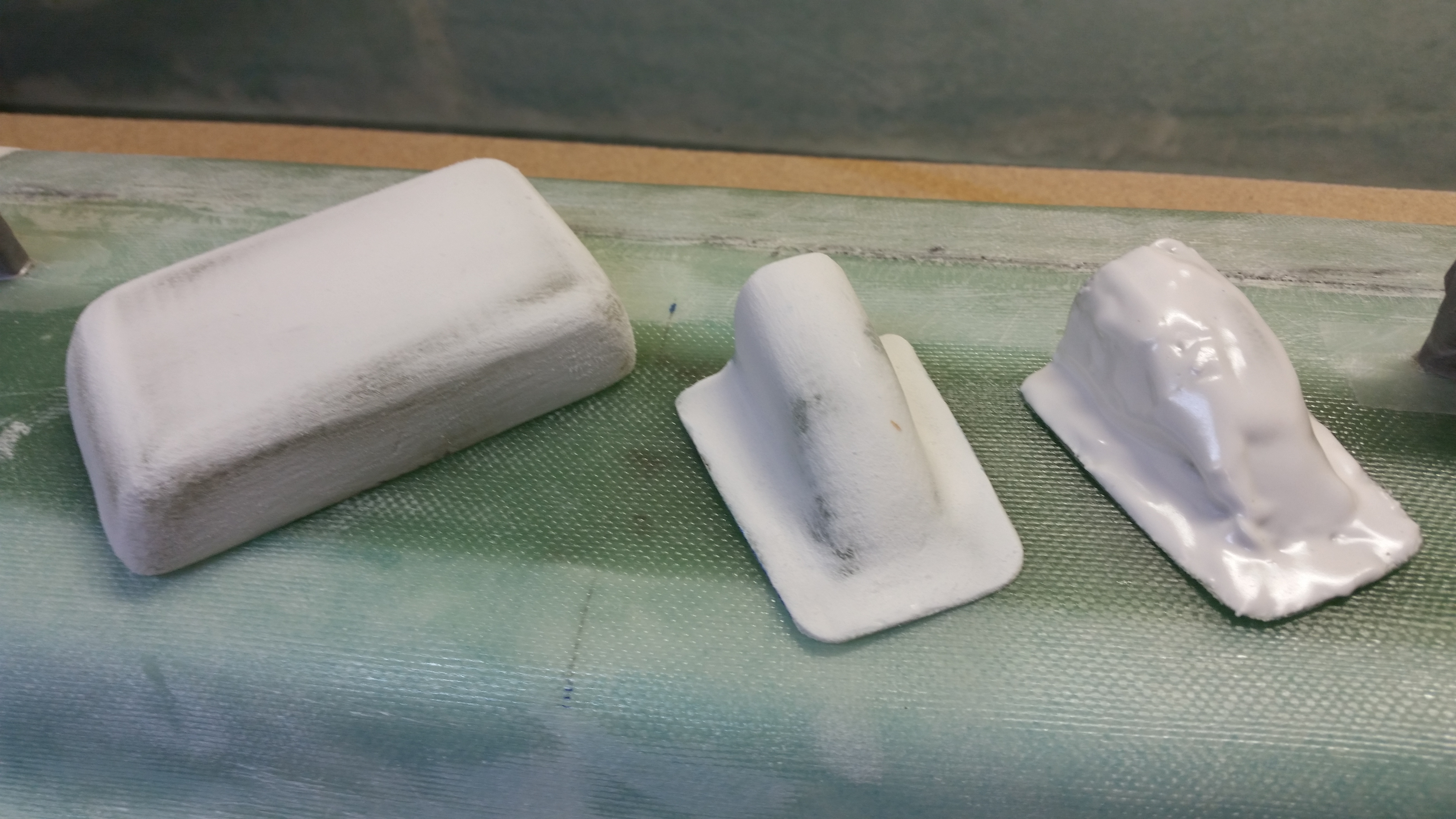
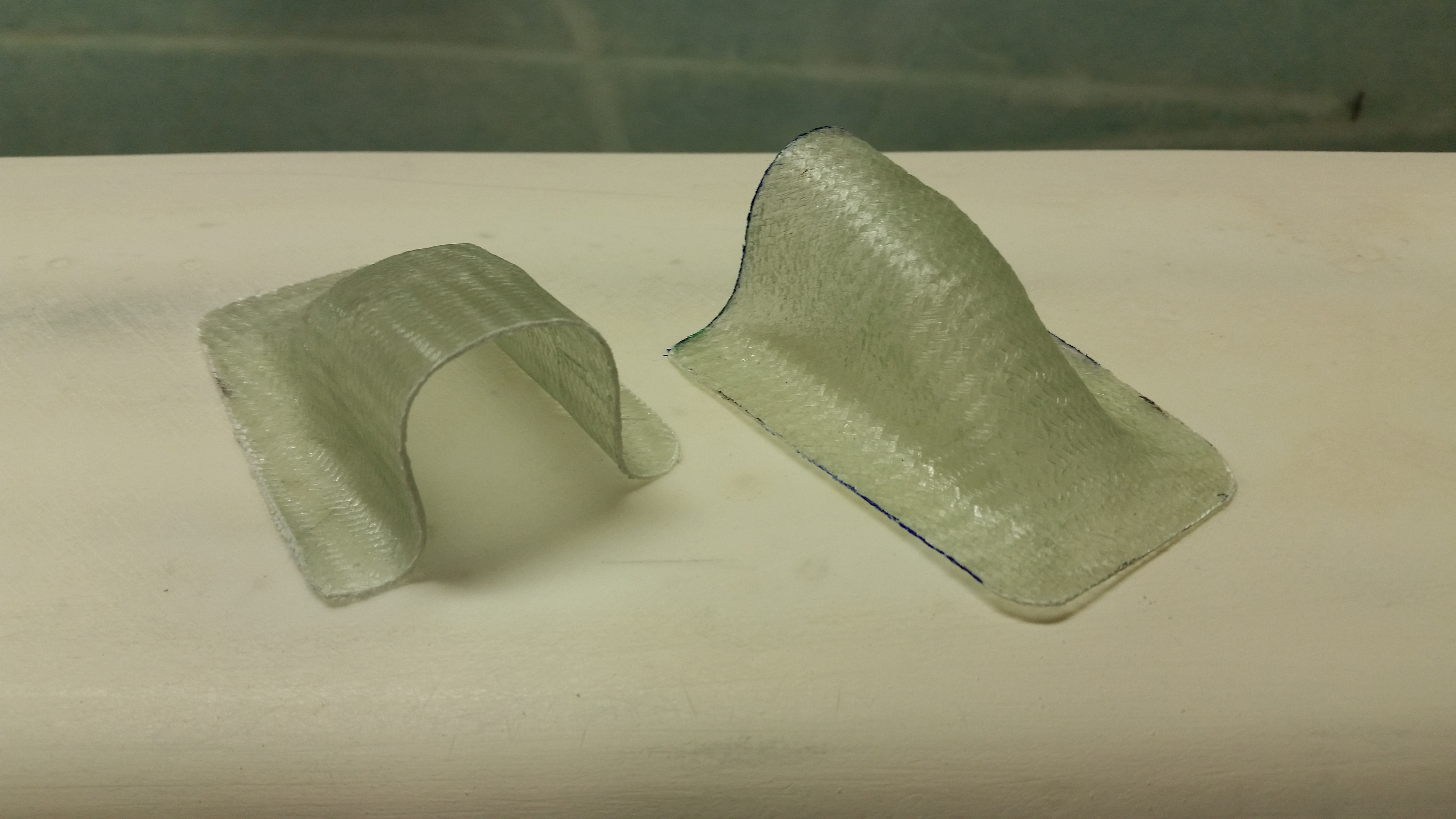
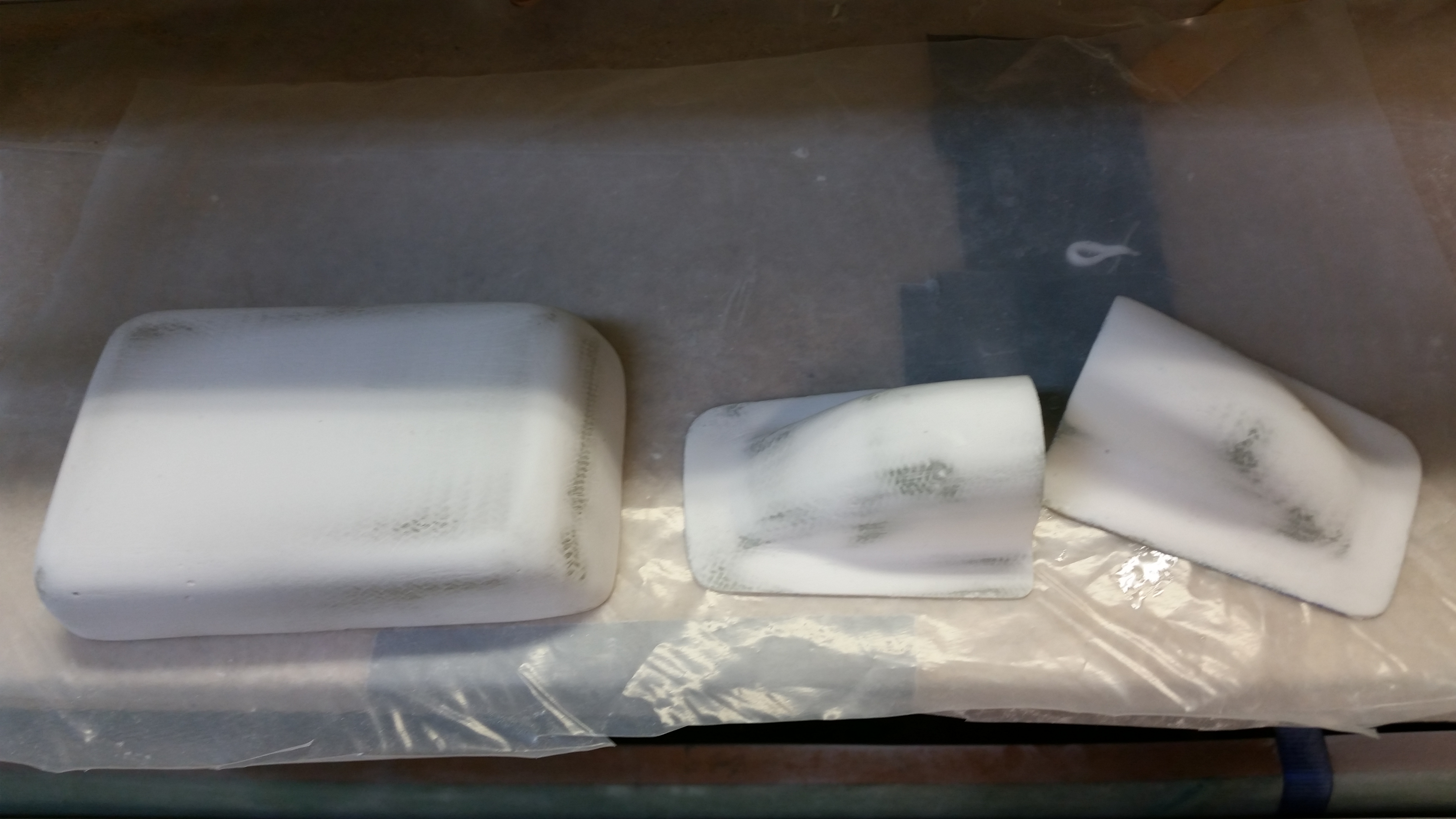
Finally, since I was working with a ton of micro finish, I also finished the various small parts I have in the works such as the ice shields and the GPS antenna cover from atop the modified headrest.

Here is an example of cheese grating vs not cheese grating:

Cheese grating vs no cheese grating

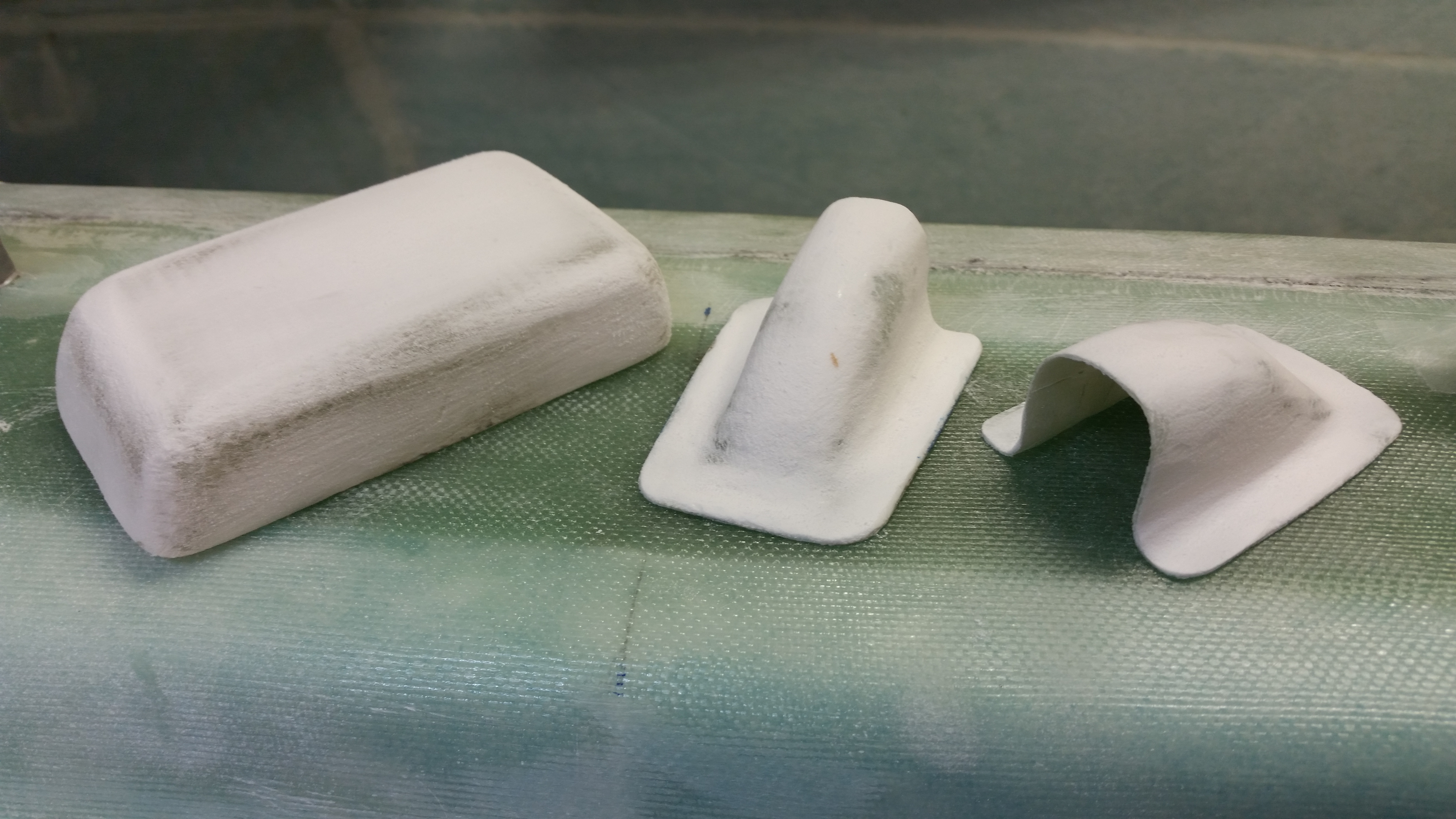
And then when all are cheese grated:

Cheese grating wins!!


Chapter 11 – One redo please?!

I will apologize right up front for not getting the requisite pictures that I promised of the elevators in their progressive state.  I will attempt to tell the story better visually as it progresses.  Right now I have the offending Right elevator with one Micro Skim coat applied to the underside of it and I will be sanding it down & applying either another Micro Skim coat or a pure epoxy wipe tomorrow.

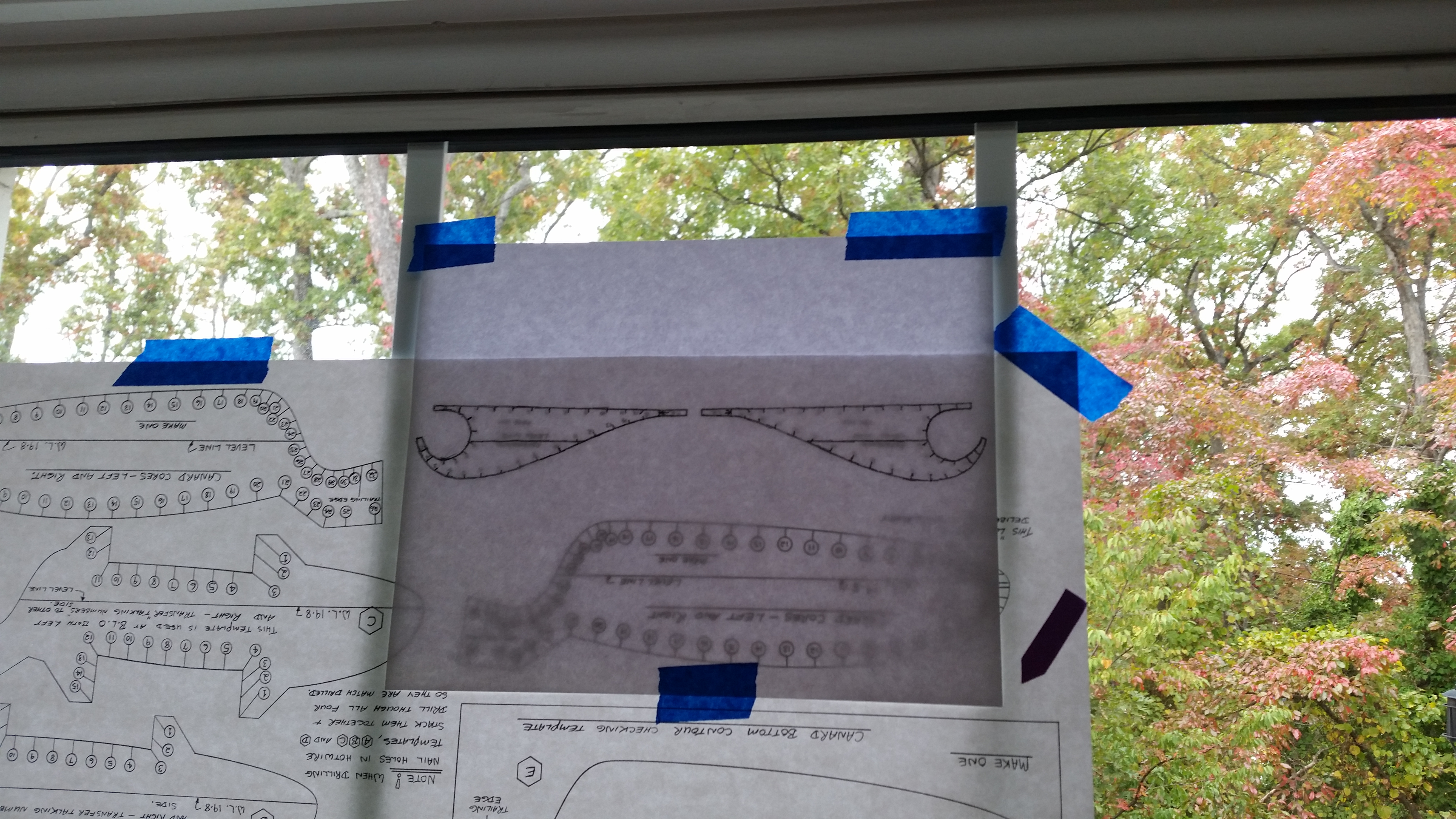
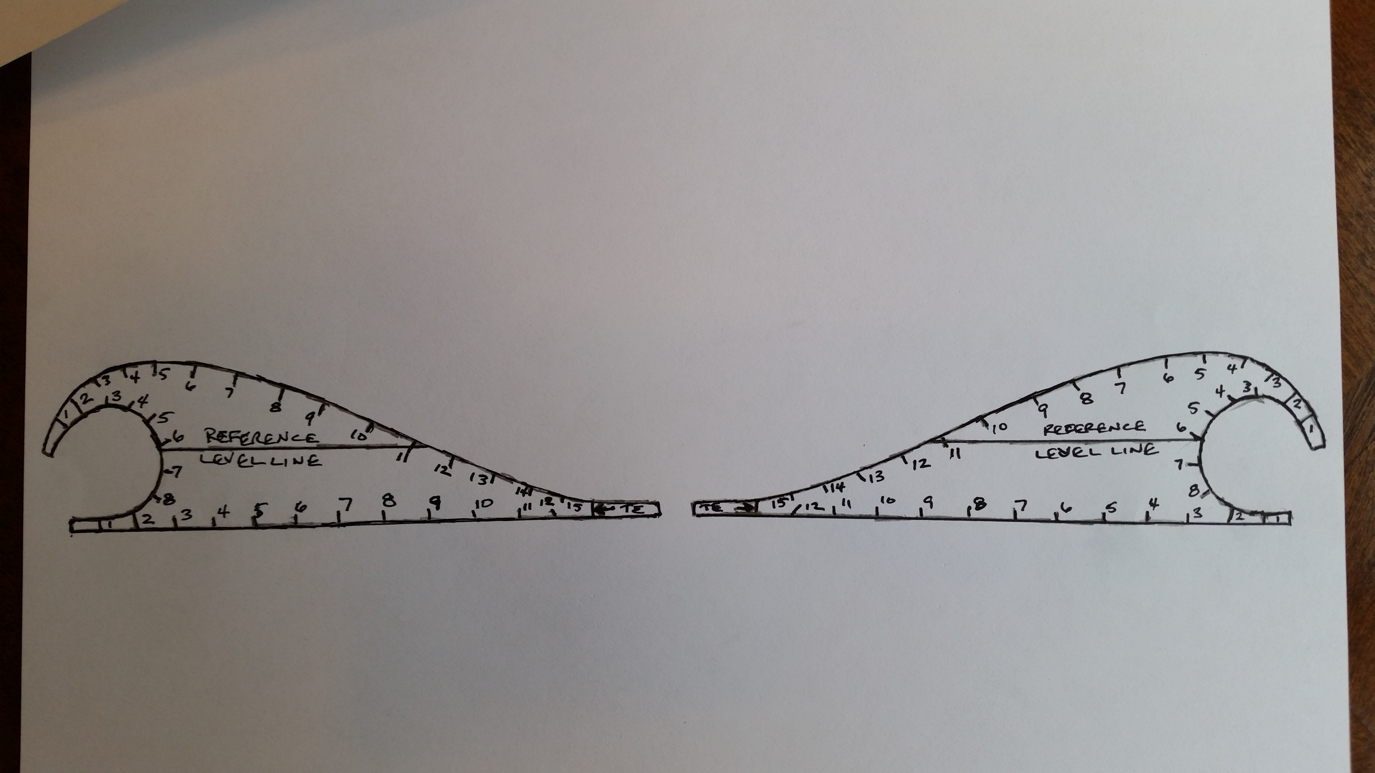
In the mean time, to ensure I have everything I need to hot-wire another elevator, I traced the Roncz elevator templates off the plans onto a piece of paper.

Tracing Roncz elevator template

Which resulted in this:

Tracing Roncz elevator template

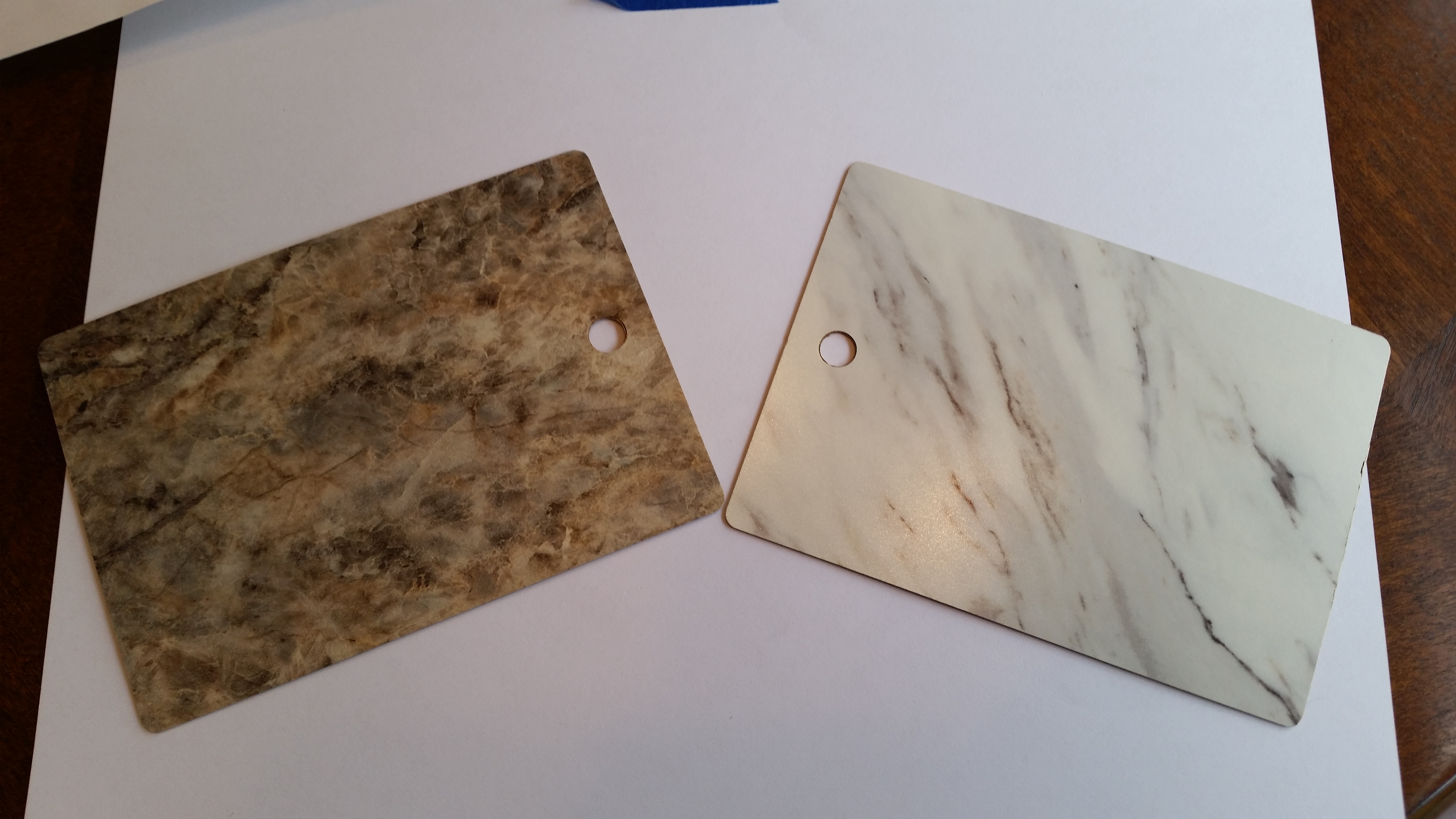
I had been to Home Depot earlier getting various items for the build, including a 2×4 to lengthen my hot-wire cutter.  While there, I found these Formica samples in the cabinet aisle, so I snagged them.  Not bad for free!

Formica samples

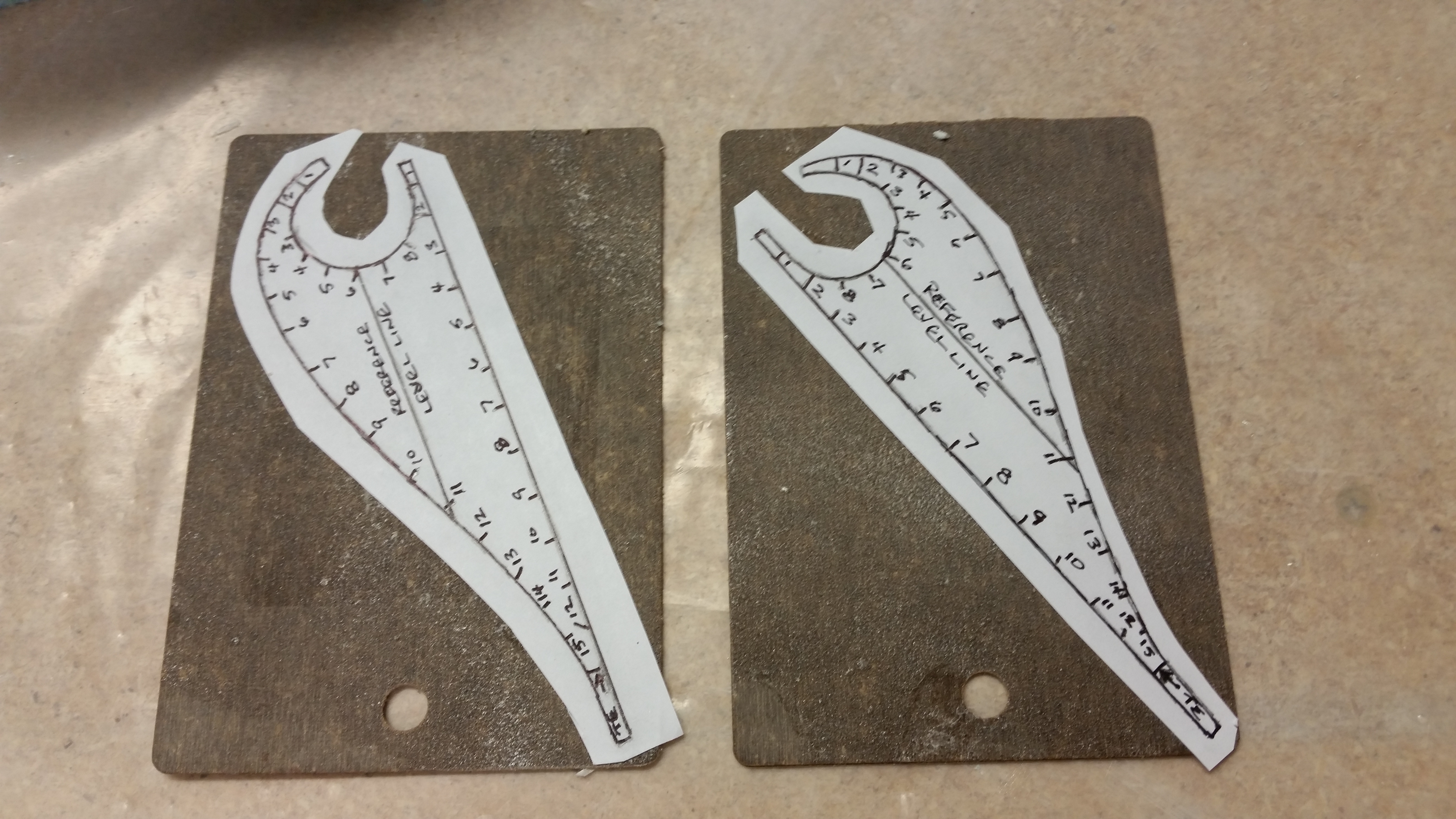
I then spray glued the elevator templates, after rough cutting them, to the Formica samples.

Templates glued to formica chips

OK, I’m going to get on a huge soap box here!  I have learned a ton from many who have gone before and completed these airplanes, but in general, there are many builders who are like birds in a nest squawking the same old tired songs.  I read in the plans (the culprit) and then in a million and one places that Formica is the best for hot-wiring templates. Now, I admit I could have done something wrong in my application of employing Formica in creating my elevator templates, but the bottom line IMO is that Formica sucks!!!!  It broke, shredded, snapped, crumbled, etc. as soon as my jig saw touched it.  So, after getting ready to go back to the store to buy some stuff that ACTUALLY works!! I found an old license plate that would work.  So, instead of using the worthless piece of crap Formica,I moved on to metal:

Formica blows! Moving to metal!

Ok, again, no pics here.  But in the end it didn’t matter what I used.  After messing around & testing my hot-wire saw, it’s just plain old & tired.  I test drove it using the metal elevator templates I made, but it just didn’t have enough oomph to cleanly cut the foam.  I thought I would at least try.  So, instead of spending more money on getting new parts for the hot-wire saw, and more time, I’m punting and will simply order another elevator core (technically a pair) from Steve at Eureka CNC.

Finally, just thought I’d throw in a pic showing that I finished & trimmed the canard ice shields:

Ice shields - trimmed