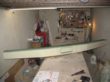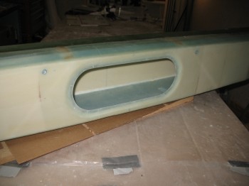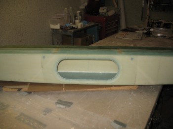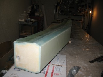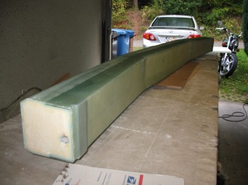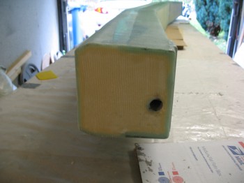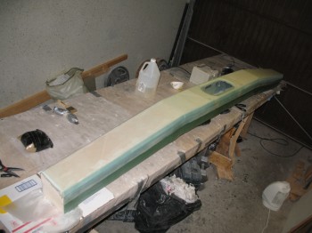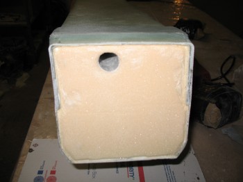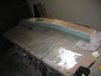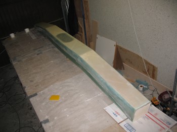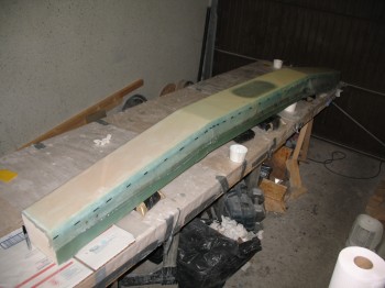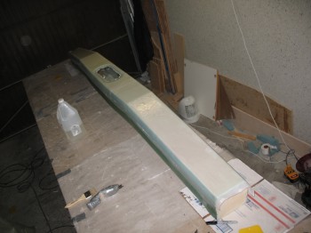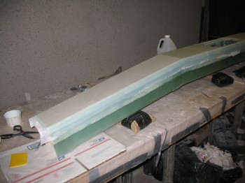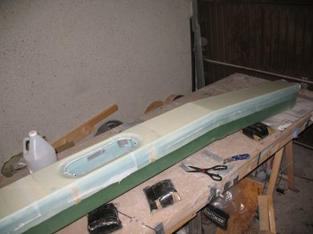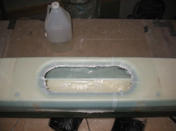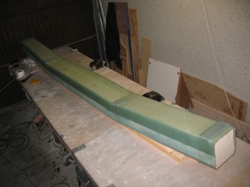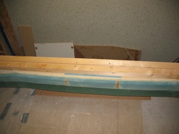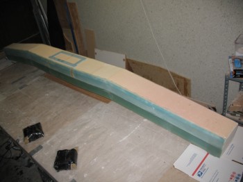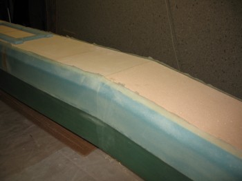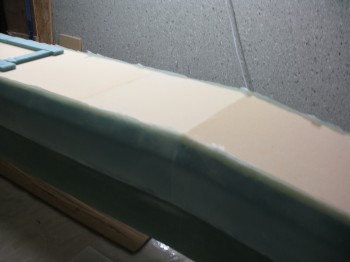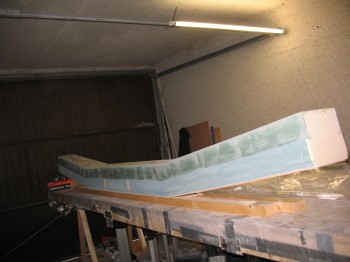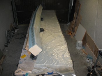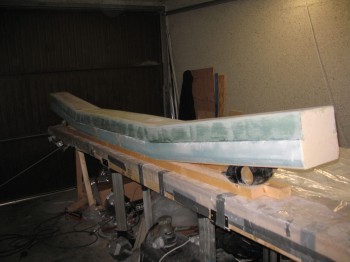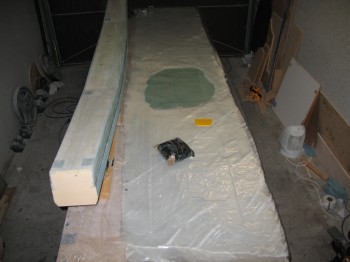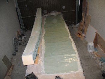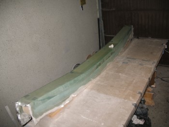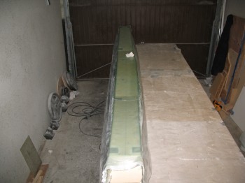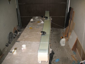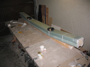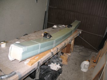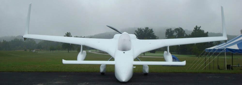
Chapter 14 – CS Spar finishing touches

Today I had to go pick up some more items at the BX on base & Praktiker to prep for the canard build.

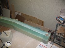
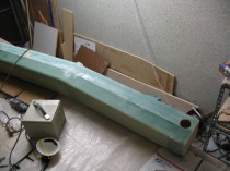
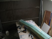
It had been over 6 months since I stepped foot into my garage workshop, and this was what it looked like:
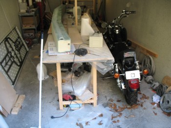
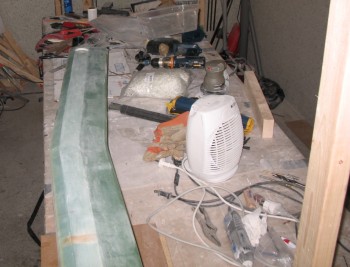
Workshop . . . 6 months later

Chap 14 - CS Spar

I was in a mad dash when I left here trying to get on with my deployment to Tampa, so I took a fair amount of time cleaning up the garage work shop to get it back into build shape.

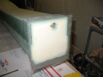
My first order of business was glassing in the 1-ply BID corner tapes at the corner junction between the interior bulkheads and the interior surface of the front face of the spar.  The CS spar is of course a torque box in many respects, so it’s made to carry & handle twisting and other various loads, so I’m not trying to make these corners solid immovable forces, I just want to add another solid attach point to the front face of the spar, which is merely bonded on via micro to the foam edges of the top & bottom surfaces.  To be sure, there’s glass that wraps around the outside of it, but there’s no interior glass-to-glass attachment along the interior front face of the spar.
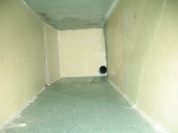
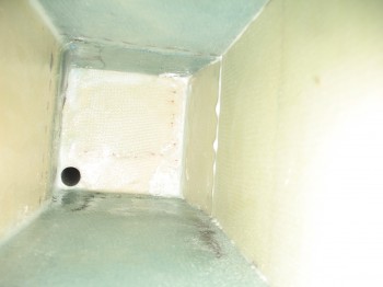
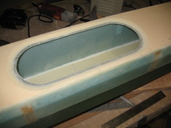
Interior bulkhead (front is to left)


This is an interior shot looking towards the right side of the spar.  The inside front face of the spar is to the left.

← Front
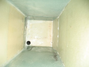


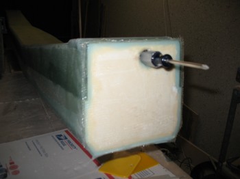
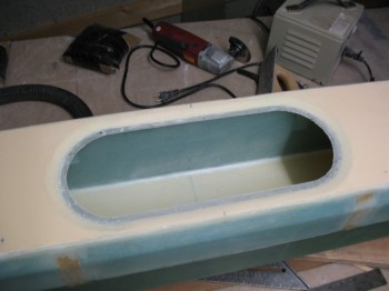
Interior bulkhead (front is to right)

This is an interior shot looking towards the left side of the spar.  The inside front face of the spar is to the right.

Front →


Again, the goal here is to glass a 1-ply BID tape layup into the corner of the bulkhead and front interior face (opposite the antenna & electrical cable conduit hole).  Also, this is not per plans.  Adding these two 1-ply BID corner tapes is an additional mod to the plans.

I cut 2 pieces of BID, set them up into 1-ply BID pre-pregs.  I then started by filleting the corners with a small amount of micro, that had just a dash of flox and Cab-o-sil mixed in to give it some umph.
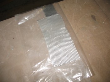
BID pre-preg

The actual order went along like this: I mixed the micro first, holding back some epoxy to wet out the pre-preg setups. Once the micro was ready to go, I wet out the 2 separate plies of pre-pregged BID.  Then I filleted the corners, with my 1-ply BID tapes at the ready once the filets were in place.

Now, the challenging part of all this was that I couldn’t see anything that I was doing. These two layups were done completely in the blind & only by feel, having to reach my arm way up into the interior of the spar on each side.  One of the reasons I had the camera on hand was to use it to check my work.

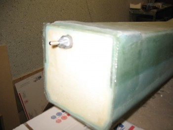
I laid up a 1-1/4″ x 5-1/4″ 1-ply BID tape into each corner on the left & right side of the spar.
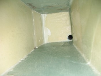
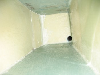
1-ply BID tape (front/left corner)1-ply BID tape (front/left corner)

1-ply BID tape (front/right corner)

The first two pics above show the right side corner BID tape, while the pic immediately above shows the left side corner BID tape.

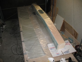
Once the interior corner BID tape layups were glassed, I set the spar aside and started building the jig for the Roncz Canard build.
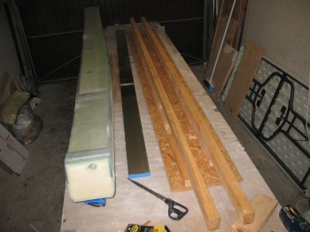
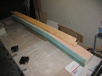
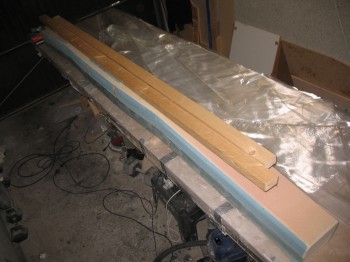
Chap 14 - CS Spar & Chap 10 - CanardTo make the canard jig as straight as possible, I mounted the 2×4’s first in an “L” shape to each other (one “L” for the front, one “L” for the back).  I then mounted these 2-piece 2×4 “L” shapes to a straight panel of OSB flooring material.  This all worked to make a pretty darn straight jig for the canard build.
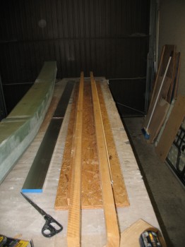
Chap 10 - Canard jig build


Chapter 23 – Throttle handle & Prop extension

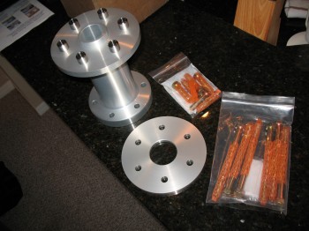
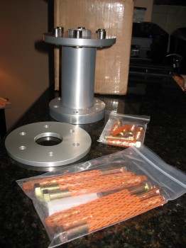
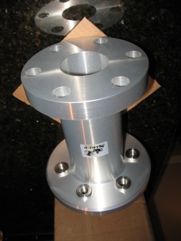
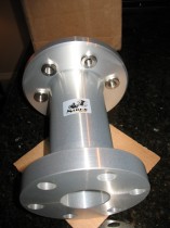
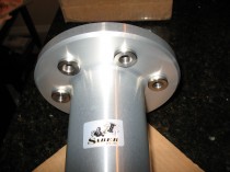
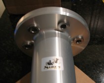
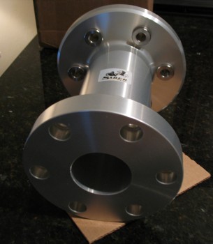
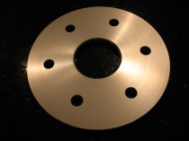
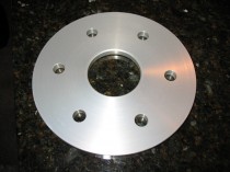
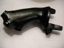
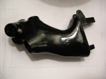
In March I was focused some on the engine & figuring out some of the components I needed.  I had put an order in with Sam Tillman at Saber Manufacturing for an 8-inch prop extension.  Sam of course does some amazingly high quality work.  Very nice.
Chap 23 - Saber 8" Prop Extension

Chap 23 - Saber 8" Prop Extension

Chap 23 - Saber 8" Prop Extension

Chap 23 - Saber 8" Prop Extension

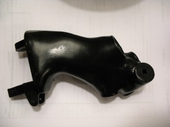
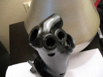
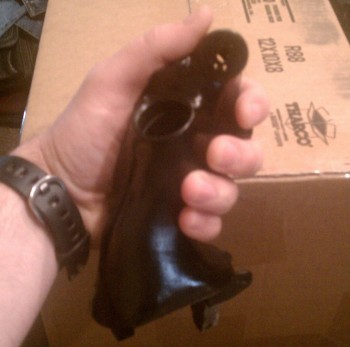
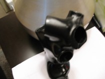
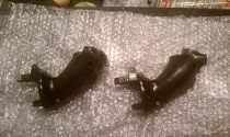
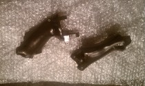
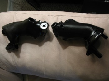
Another serendipitous find I made was a local manufacturer that makes certified parts for military aircraft simulators.  I guess because it was the holiday season, and since my buddy Marco wanted one as well, I was able to talk them into doing a two-unit production of some F-16 throttle handles.  Since instrument panel space is limited in a Long-EZ, I want to put a number of switches on my throttle handle along with my grip stick to attain the highest level of HOTAS (Hands-on-Throttle-and-Stick) as possible (I listed the throttle as Chapter 23 since it’s actually not covered in the Section I plans, but rather in the Section IIL plans which covers engine installation exclusively).

Chap 23 - F-16 Throttle

Chap 23 - F-16 Throttle

Chap 23 - F-16 Throttle

Chap 23 - F-16 Throttle


Aircraft Welding

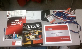
The first weekend in March I attended the EAA SportAir TIG Welding Workshop in Griffin, Georgia.  Great class!  I would highly recommend it for anyone who is looking to do TIG welding specific to Aircraft building, both with 4130 steel and aluminum.

EAA Welding Class, Georgia

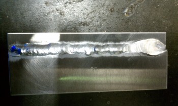
This is my first experience welding aluminum . . . what a different animal.  Glad I’ll only be working with 4130 steel for my rollover assembly.  Still, it was fun to try something new.

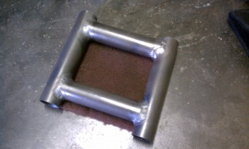
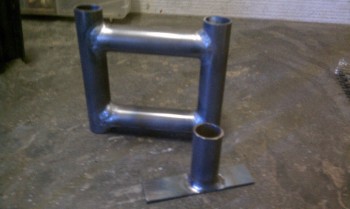
My first Aluminum weld bead (tricky stuff!)Below are a couple of practice projects we did in the workshop.  I added a few pieces to a few them of them to make it a little more realistic.  Our instructor was fantastic and really helped lock in our TIG site picture, pointing out how to improve our techniques & showing us a few tricks.  It helped immeasurably.

EAA Course - welding 4130 tubing EAA Course - welding 4130 tubing


Chapter 14 – Das Spar ist Kaput!!!

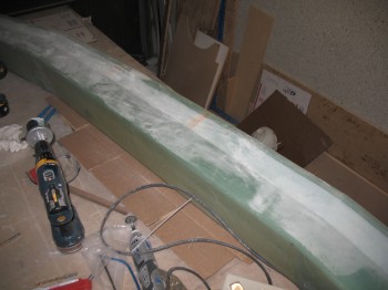
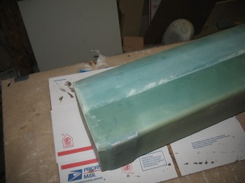
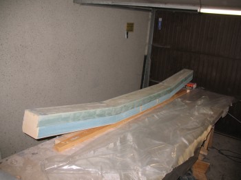
I started off today by lightly sanding the CS spar to remove all the excess epoxy that was all over the outer skin of the spar from the various layups & me handling it with sticky gloves at times.

Chap 14 - CS Spar Final Sanding

Once I finished sanding it, I vacuumed the entire spar, inside & out.

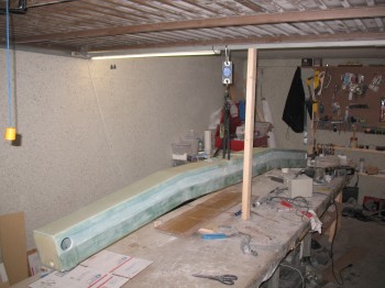
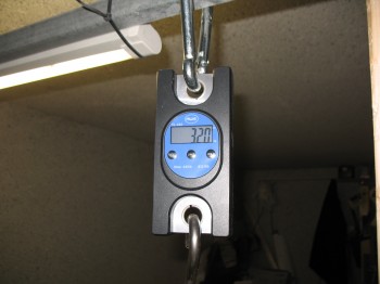
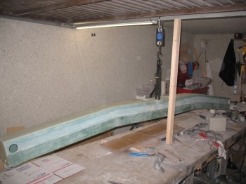
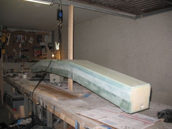
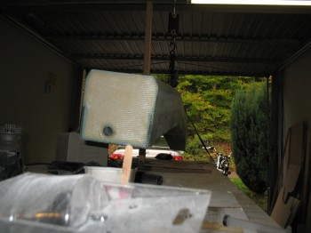
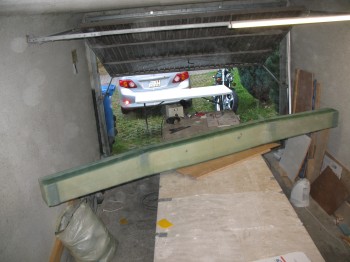
I threw a piece of scrap wood in as a support strut underneath the garage door crossbar & then attached a hanging “fish” scale to weigh the spar.

Chap 14 - Weighing CS SparChap 14 - Weighing CS Spar

Mike Melvill, in CP 25 (maybe 26?) listed out the weights of his Long-EZ components.  His CS spar was 29.5 lbs.  So my spar is about 2.5 lbs heavier than his.  Not bad, especially since I used the heavier blue foam.  But I did use the new UNI layup as well, so it should have probably equalled out.  Oh well, one thing I definitely didn’t have helping me out were the Aliens that obviously he, Burt & Dick had helping them out! . . . ‘cuz their low build weights are definitely alien to me! yuk, yuk!

I’ll comfort myself with a quote that is oft heard in the US military, and oddly enough was actually credited to Soviet Admiral Sergei Georgievich Gorshkov:

“Perfect is the enemy of good enough”

(Yes, it’s come down to me quoting Soviet Admirals to justify my shoddy workmanship!  Ironic? Or just time for me to take a break from building?!  ha!)

Chap 14 - Weighing CS SparChap 14 - Weighing CS SparChap 14 - Weighing CS Spar


Chapter 14 – CS spar… final steps

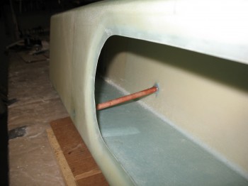
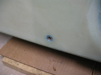
I started off today by installing & floxing into place the phenolic tubing that will be the conduit for the Nylaflow rudder cable conduit as it traverses the CS spar front & aft walls.

Chap 14 - CS spar rudder cable conduit

Again, I’d like to reiterate that these holes were created in the glass layups on both the inside & outside walls by carefully separating the glass fibers so that they went AROUND the holes.  No glass (or shall I saw the minutest amount) was cut or drilled to install this phenolic tubing.

Chap 14 - CS spar rudder cable conduitChap 14 - CS spar rudder cable conduit

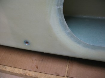
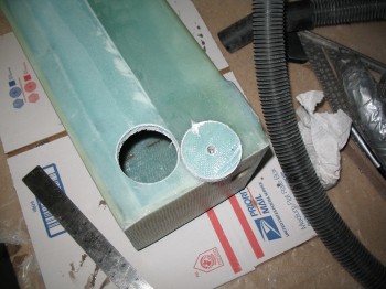
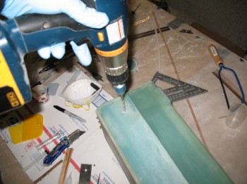
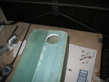
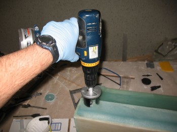
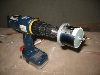
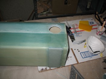
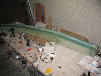
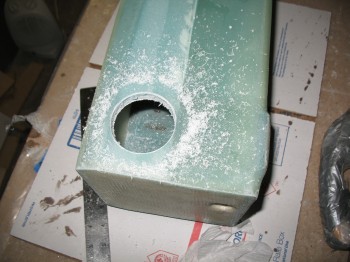
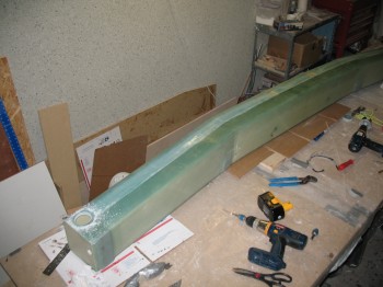
I then measured out & drilled a 2-1/4″ hole (approximately, I was using German hole saw bits so it was ~57mm) on each end of the spar on the bottom to allow access to the wing spar bolts.

Chap 14 - Spar bolt access holeChap 14 - Spar bolt access holeChap 14 - Spar bolt access holeChap 14 - Spar bolt access holeChap 14 - Spar bolt access holeChap 14 - Spar bolt access hole

After I drilled the holes, I Dremeled out the foam just a bit along the edge of the hole, cleaned everything up, and then dry micro’d the edges of the hole.

Chap 14 - Spar bolt access holeChap 14 - Spar bolt access holeChap 14 - Spar bolt access holeIMG_0014Chap 14 - Spar bolt access hole


Chapter 14 – CS spar end caps

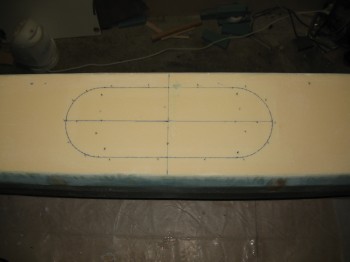
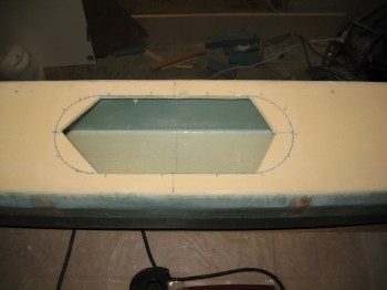
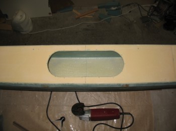
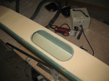
Today I started by using the Fein saw (again, I call it that for ID purposes, but mine is actually a cheapo version from Harbor Freight… but it works great!) to remove the overhanging glass on each end of the spar & on the straight runs of the oval access hole.

I then focused on the oval access hole with the Dremel tool.  I knife trimmed it as well to remove all the excess/overhanging glass.  I also used my Perma-Grit tool and sandpaper to smooth out the access hole edge and surrounding glass.

Chap 14 - CS spar end caps

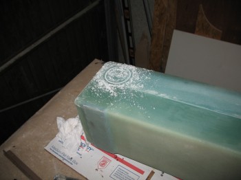
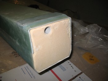
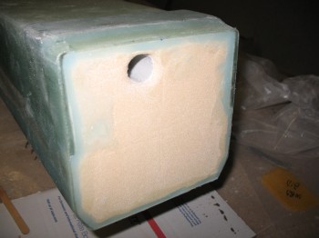
I used a 7/8″ bit to drill out the foam covering the electrical wire/antenna cable conduit at each end of the spar.  I sanded it to round over the edge of the hole for a nice radius.

I then Dremeled out a narrow wedged-shaped channel into the foam at each end of the spar around the inside edges of the glass.  I removed the foam on the inside of the glass to maybe 1/4″ deep max.

IMG_0002Chap 14 - CS spar end caps

I sanded the foam faces at each end of the spar, vacuumed the end bulkhead surfaces & prepped for glass.

First, I cut 2 pieces of 7.5″ x 7.5″ of BID at a 45° bias.

Then I floxed the edges of the glass into the channels I had just created in the foam.  What this does is create a fillet in the corner between the existing 4 sides of the glass & the newly laid glass.  Once it cures, there will be a very solid “triangular” (as best possible) corner bead that will greatly increase the strength of the corner, and also the bulkhead’s glass ply covering.

Chap 14 - CS spar end capsChap 14 - CS spar end caps

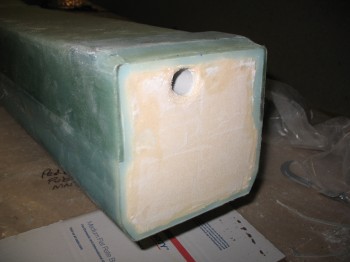
I micro’d the remaining foam in the middle of the end bulkheads.  I then wet out the pre-pregged 1-ply of BID…. which is hard to see with only one ply.  I then glassed each end of the spar with the 1-ply BID pre-pregged layup.

Chap 14 - CS spar end capsChap 14 - CS spar end caps

I trimmed the excess glass with my Dritz scissors (still awesome!) & then made an X-cut in the glass over the hole and plugged each one so the glass would wrap around the radiused edge of the hole and cure securely onto the interior of the channel conduit.

Chap 14 - CS spar end capsChap 14 - CS spar end caps


Chapter 14 – CS spar final side glassed

I started off today by refilling some more hardener & consumables.

I cut 11-1/2″ wide UNI strips across the full length of the roll at 45° . . . enough for a 2-ply layup across the front face of the CS spar.  I also cut an 11″ x 22″ 1-ply BID piece at a 45° bias for reinforcement around the center spar access hole.

I had a couple delams right along the edge of the angled/wedge corner … apparently I didn’t squeegee it well enough and gravity did it’s work & it separated just a hair.  I quickly gave it an injection of epoxy.

I used a flox/micro mix for the edge & edge divots.  I also added some flox around the edge of the hole as a base layer since the glass was thin but still a bit rough from how it had cured before.

Chap 14 - Glassing final sideChap 14 - Glassing final side

I glassed Layup #8 (2-ply UNI ± 45° … so 90° angle to each other).  As I laid up the glass, I very carefully separated the glass fibers around the holes for the rudder cable conduit, just as I had done with the glass on the back of the spar.

Chap 14 - Glassing final side

Chap 14 - Glassing final side

I glassed the 1-ply BID around the the oval access hole & then peel plied the entire layup.

Chap 14 - Glassing final sideChap 14 - Glassing final side

Chap 14 - Glassing final sideChap 14 - Glassing final side


Chapter 14 – CS spar prep for final glass

I started today by refilling the slow hardener bottles & cleaning the Dritz scissors.

I then removed the peel ply from the CS spar, cleaned up & removed the peel ply strings & goobers from the layup.

Chap 14 - CS spar build

I used the Fein saw to cut the glass flush at the CS spar end.
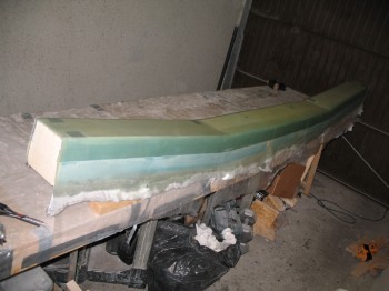
Chap 14 - CS spar buildChap 14 - CS spar buildChap 14 - CS spar build

After cleaning up the end glass on the spar, I removed it from its 2×4 mounts.
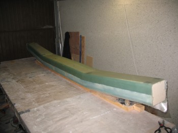
Chap 14 - CS spar buildChap 14 - CS spar buildChap 14 - CS spar buildChap 14 - CS spar build

I again used the Fein saw to trim the glass along the top & bottom edges (at the angled/wedged corner) so it was close to the foam.  I hit the edges with a hard sanding block as well.

Chap 14 - CS spar build

I cut the 5″ x 14″ oval access hole on the front face of the CS spar.

Chap 14 - CS spar buildChap 14 - CS spar buildChap 14 - CS spar buildChap 14 - CS spar build

I removed the peel ply at the edge of the oval hole & sanded a beveled transition around the cutout.

Chap 14 - CS spar buildChap 14 - CS spar build

I then sanded the entire front face & Dremeled out any dead micro & epoxy.

Finally, I vacuumed the entire spar & the surrounding work bench.


Chapter 14 – One big layup!

I started off today by mounting two long 2×4’s to the middle of the 5″ x 14″ oval access panel.

Chap 14 - Mounted glassing base

I used 3″ long drywall screws & the nice part is that it’s drilled to glass that will simply get removed and chucked.

Chap 14 - Big layup #6

Chap 14 - Big layup #6

I laid out the plies of UNI & cut plastic for the pre-preg.

Chap 14 - Big layup #6Chap 14 - Big layup #6

I micro’d the foam with both dry micro & microslurry.  I then wet out the pre-pregged UNI.

Chap 14 - Big layup #6Chap 14 - Big layup #6

I then laid up the pre-pregged UNI glass onto 3 sides of the spar: top, aft & bottom.  This is the plan’s Layup #6.

Chap 14 - Big layup #6Chap 14 - Big layup #6Chap 14 - Big layup #6Chap 14 - Big layup #6

I cut the edges on each side close to the 1/2″ x 1″ wedge cutouts on the front corners of the spar.

I then floxed 2 each LWA3 aluminum extrusions & 2 each LWA3 aluminum extrusions on top of the existing Inboard & Outboard extrusions.  I covered the LWAs with the UNI & BID plies that I cut on 24 Sep.

I then peel plied the entire layup & weighed down the Inboard extrusions.

Chap 14 - Big layup #6Chap 14 - Big layup #6Chap 14 - Big layup #6