Sep 26-28
Researched electrical system (reading Bob Nuckolls’ The AeroElectric Connection) & ordered components from B&C.

Sep 26-28
Researched electrical system (reading Bob Nuckolls’ The AeroElectric Connection) & ordered components from B&C.
I set up the heaters today to get the garage/workshop ready for the big layup #6 glassing, but I couldn’t get it heated past 62°F.
So I pre-deployed the cut glass to the garage & decided to wait until Saturday to do the big layup (so I could glass during the day while the weather is obviously the warmest).
Today I cut 2 sets of the Outboard UNI extrusion caps: 3″ wide x 12″, 14″, 16″ long.
I also cut 2 sets of the Inboard UNI extrusion caps: 3″ wide x 8″, 10″, 12″ long.
Finally, I cut 2 sets of BID for the final Outboard extrusion layup glass ply (5″ x 6″) and 2 sets for the final Inboard extrusion layup glass ply (5″ x 8″).
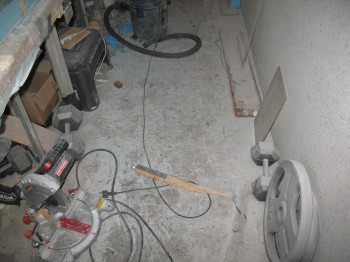
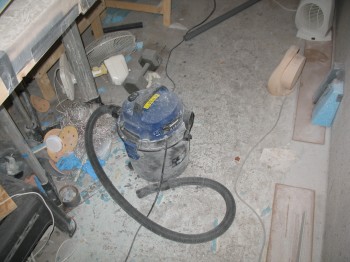
Today I started by cleaning the shop. As you can see the sanding to knock down the steps and get the spar surface smooth has left the shop a complete fiberglass & foam dusted mess.
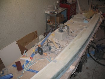
After I got the shop cleaned up, I measured, cut, fitted & micro’d the top 2 Spruce wood hard points.
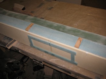
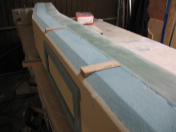
I also sanded the spar cap corners so they would be radiused when it was time to glass the spar skin.
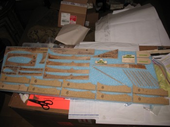
Today I started the build at the base wood hobby shop. I cut the remaining “L” templates for the Roncz canard, and cut outlines of the CS109 cockpit control system mount & RT3 Roll Trim bracket. Additionally, I cut 10 x 6″ dowels & 1 x 12″ dowel for the Roncz canard & sharpened them all to a good point using an old school pencil sharpener.
I used a coping saw to cut off the remainder of the 1/2″ x 1″ wedge-shaped angle on the front corner of the CS spar. I then sanded to shape the angle on the front corner to finish it.
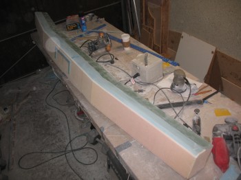
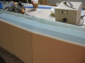
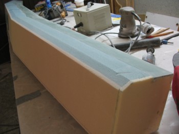 I shaved just hair off the length of the top Spruce wood hard points so that they were just under 3″ in length.
After I mocked up the Spruce hard points for a good trial fit on the spar top side, I flipped the CS spar and belt sanded the spar cap “steps” to smooth out the spar cap surface. I also hit the bottom spar cap with the orbital sander just to smooth it out a touch more. I then sanded the foam of the bottom side just in front of the spar cap to match the foam & spar cap to each other & smooth out the entire bottom spar surface.
I Dremeled all along the joint between the spar cap & the foam on both the top & bottom side of the spar, down the entire length of the spar caps to remove dead micro, flox, epoxy & glass.
I made a trial fit of the Spruce hard points on the bottom side of the spar after marking, cutting out & removing the foam. I trimmed the bottom Spruce hard point blocks by almost 0.1″ in height to allow room for the micro that would be used to bond them in place. I then mitered the angle on the front of each Spruce hard point to match the angle on the spar face foam.
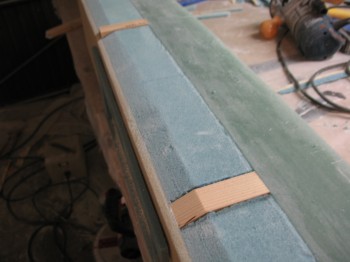
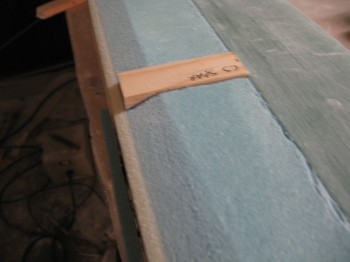
After all the prep was complete, I micro’d in the 2 bottom Spruce hard points.
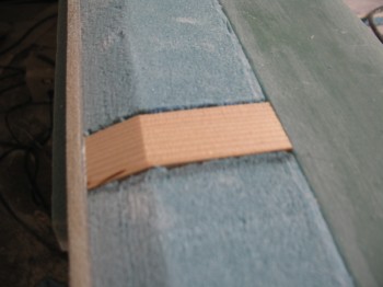
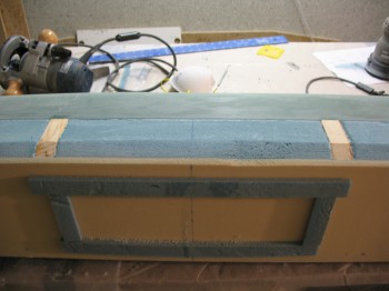
I then cut the 4 layers of UNI for the final wrap of the top, bottom & back faces of the CS spar (layup #6). The front face of the spar is left to glass until last and accounts for the access hole in the front of the spar and also overlaps onto layup #6.
I checked the lower spar cap layup first thing… it looked good!
I pulled the peel ply & Fein-sawed the ends off level with each end bulkhead.
I then removed the dams & chiseled off the residue. I sanded the aft face of the CS spar to remove the dead bondo, epoxy, etc.
I then belt sanded the upper spar cap to level out the “steps.” The steps are the end of each subsequent layer of 3″ UNI glass after it cures. The stuff is so thick that even though it gets peel plied, there is a very visible step at each layer of glass in the spar. The belt sander helps smooth it out so that it’s not TOO lumpy when the spar gets it’s final wrapped glass skin.
A builder’s tip on laying up spar caps I received AFTER I glassed 6 of the 8 spar caps on this bird (the last 2 are on the canard) is to pull the individual strands in each layer of 3″ UNI tape so the are very staggered on each end. You still have the same amount of glass, it’s just spread out over a broader area…. so doing it the easy & efficient way is fine for some builders, but I’ll stick to my knuckle-dragging Neanderthal ways thank you very much….ha! (sheesh . . . )
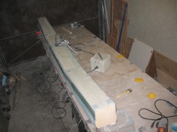
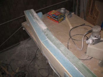
I also sanded down the foam adjacent to the spar cap to make sure it was level & smooth.
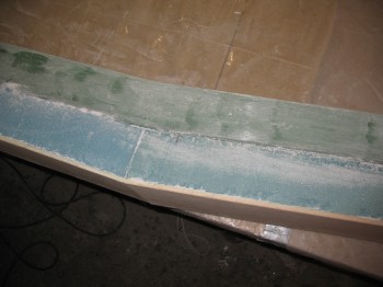
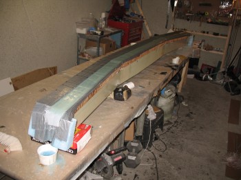
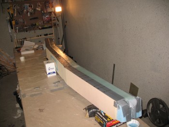
Below are some good shots of the wing-to-spar bolt extrusions & the CS spar caps.
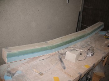
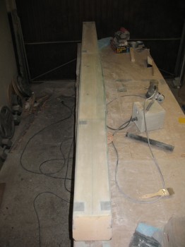
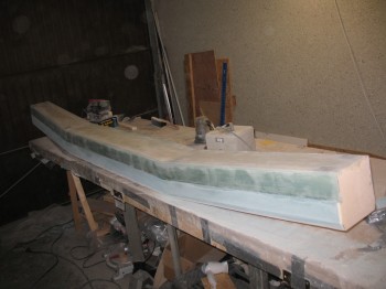
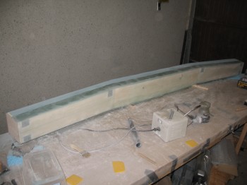
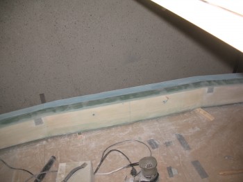
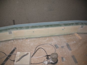
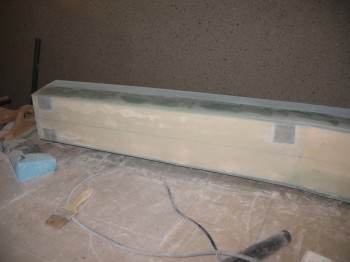
Since sanding is so fun, I continued on in my material removal quest by starting in on removing the front corner wedge. This wedge is removed to create an angled corner “LE” on both the top & bottom that will eventually receive the also-angled glassed foam top & bottom skins of the strake. In fact, the front Outboard faces of the CS spar makes up the aft wall of the fuel tanks and are forever hidden (hopefully) within the strakes once everything is all glassed up.
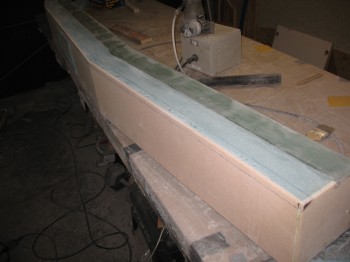
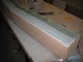
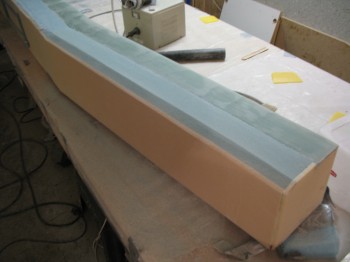
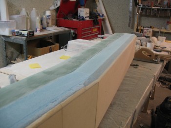
I’ve mentioned it before, but it’s amusing to me how a number of steps spelled out in the plans look so benign, simple and minimal in effort . . . until you start the step. These front corner angles look simple enough to remove the material, but it took quite a while and a fair amount of work. It probably didn’t help that I used the much tougher blue PVC vs the easily-carved Urethane foam in my construction of the CS spar. Even still, I’m happy with my choice to use the blue foam.
I took a break from shaping the corner angles & grabbed my Spruce wood hard points that get embedded into the CS spar for the engine mounts to bolt to, as well as the fuselage longerons. I had cut those hard point inserts a while ago, so installing them was simply a matter of marking & removing the foam from the hard point locations.
Also, a week or so ago on a slow build night, I had measured out the new locations of my hard points compared to the stock plans location since my fuselage is wider. And, although my fuselage is wider, so too are my longerons. Thus, my hard point locations were only about .2″ off from the original plans location.
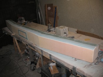
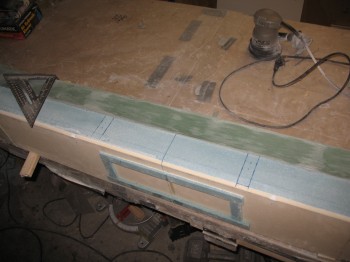
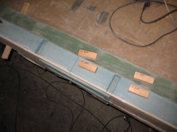
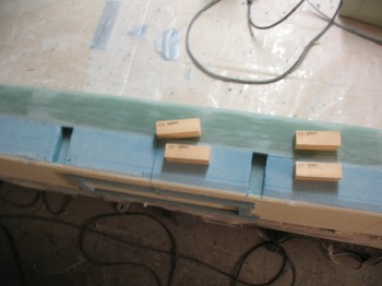
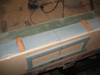
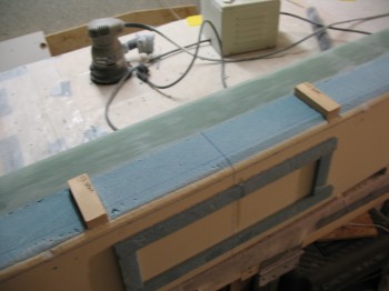
Today I removed the peel ply from the CS spar bottom spar cap trough repair layup… it looked good.
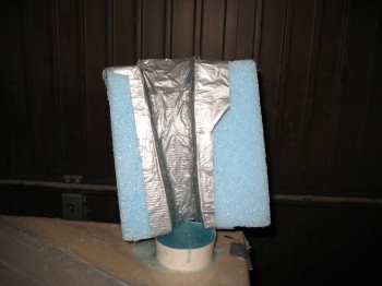
I sanded down the spar cap trough & cleaned up the peel ply goobers.
I then used 1x2s for the lower spar cap Outboard dams, and because I’m cheap (and slightly retarded) I reused a recycled piece of 1/4″ ply from the top spar cap layup for the center dam piece. I bondo’d the dam pieces to the CS spar for the lower spar cap layup.
I did a final sanding & cleanup of the lower spar cap trough & vacuumed the entire layup area. I taped the foam adjacent & lying next to the spar cap trough & then marked the BLs for the individual lengths of 3″ UNI tape that would be glassed into the spar cap.
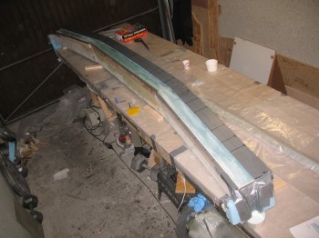
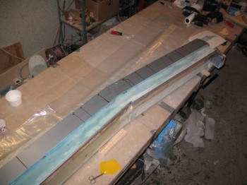
I mounted the epoxy runoffs on each of the spar and repositioned the spar lower & secured it in place. I needed it lower because hours & hours of glassing these spar caps will give you carpel tunnel & make your hands numb from the odd position they’re in while glassing.
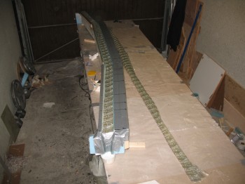
I floxed the front of the channel again just like I did on the upper spar cap, before laying in the 3″ UNI tape. I then glassed the lower spar cap. I started around 8:30 pm & finished at half past Midnight (4 hours).
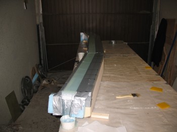
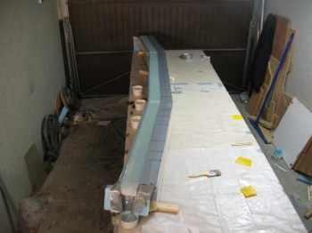
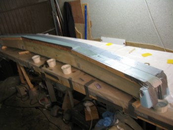
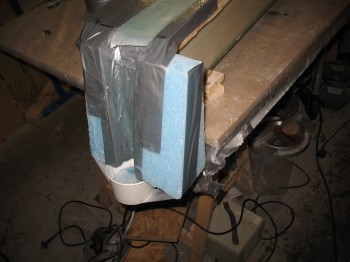
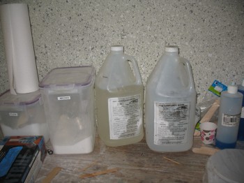
I peel plied the spar cap and called it a night. Below is the total amount of epoxy I have left from the huge container I bought in May. So far, I’ve used about 8 gals of epoxy since I’ve been in Germany.
Today I started by sanding a good majority of the plywood dam remnants off the CS spar during my lunch break. Later on, I sanded a bunch more (the 1/4″ plywood was simply a PITA to remove).
I prepped the foam near the corner of the shear web on the edge of the lower spar cap channel where I would be laying up my repair glass. I used a mixture of flox & micro on the newly bared foam. In a few spots I used straight flox for a smooth transition from foam to the existing glass.
I prep-pregged & laid up the 2-ply UNI & 1-ply BID on the lower spar cap channel. I then peel plied the newly laid repair glass.
As for pics, you are probably noticing a trend. As I transcribe my build log from my notes & put them online, I notice that documenting events tended to go by the wayside when I went into crisis/repair mode. Thus, unfortunately, I don’t have any pics of this repair. I would say that I will try to do better in the future, but my days of making any mistakes during this project are behind me, so I won’t have any to document. HA! (I wish . . .)
. . . in the airplane building world.
After cutting the ends of the spar cap even with each end of the CS spar & removing the peel ply, I flipped the spar onto its front face to remove the dam that was now not only bondo’d solidly to the CS spar, but epoxied, floxed and glassed as well (even though it’s covered with duct tape… thank God!) .
Well, when I flipped the CS spar onto its front face, I noticed a decent delam along the corner edge of the lower spar cap channel. The glass must have had issues with flowing around the corner from the rear face of the spar to the bottom spar cap channel. The delam was about 14″ long x ~0.5″ average on one side of the center line and about 8″ long with a few areas reaching 0.75″ in width on the other side.
I searched the blogs/Internet & then called Dale Martin to get a crosscheck from a seasoned EZ vet. My initial plan was to cut out the bad glass, recover with 2-plies UNI in the same orientation as called out for the original layup, overlapped onto the existing glass. I would then add a protective 1-ply BID over the entire repair.
I have to say I was feeling much better about it all after talking to Dale, especially when his recommended repair was EXACTLY what I had planned! Not to take anything away from Dale, because he really helped me through this builder’s crisis, but I was just glad that as a newb my decision-making was not too far off kilter. One of the issues that Dale honed in on was the build temps in my shop. The weather in Germany was getting much colder, and the temp swings were often distinct. Guessing on how many heaters to use & when was a constant challenge since even entering & exiting the garage by opening the one big door could keep the Mercury jumping up & down.
MGS is a German epoxy, so it’s good down to around 65° & scoffs in the face of humidity. But my personal minimums–if you will–for building was the normal 70° low end glassing ops temp target. Keeping an un-insulated detached garage, with no central air, heated during the German winter to say, 80-90° F constant, was cost prohibitive and simply wasn’t going to happen. My only other option was to stop building, which was going to happen in mid-October regardless, since I was deploying to Tampa for 6 months (the irony of having such a great Winter building location as Florida, with your entire project located in Germany!)
So I did some more research & then developed my plan of attack. I then cut out & removed the delam’d glass.
To get back on track & get back into a positive build groove, I cut the 3″ UNI tape for the lower spar cap.
I then went to the cutting table in my downstairs shop & cut the 2-plies of UNI and 1-ply of BID for the repair.
I refilled the hardener bottles & poured the last of the MGS from the large plastic container into a gallon jug.
I then went back to work removing some of the bigger chunks of the 1/4″ plywood dams. The thin ply wood worked well as a dam, but it was playing hell getting it off the CS spar because it would simple splinter & shatter when I tried to remove it since it just didn’t have the strength to stay together.
I cut & sanded the glass overhanging the edge at the end bulkheads using the Fein saw. I hit the edge with a sanding block & cleaned them up nicely. I then pulled the peel ply off the cured CS spar shear web layup. The layup looked good.
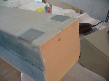
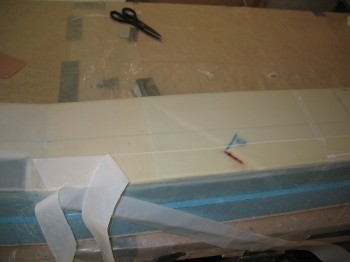
I cut up a bunch of the 1/4″ ply that had been used as the “sled” for the fuselage bottom to use as dams for the top spar cap layup. Just like the wing, a dam is required to keep the 3″ UNI tape in place as it’s laid up. Unlike the wing, which only required a dam for a small section of the spar cap channel, the CS spar spar cap sits on the entire aft edge of the spar–one on the top side & one one on the bottom–so it requires a dam the entire full length of the spar.
I then bondo’d & weighed down the dam sections into place.
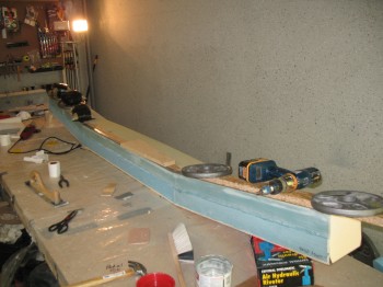
I cleaned off the table & then grabbed my 3″ UNI tape dispenser. Due the large number of cuts I need to make, I threw my UNI tape onto my table top peel ply dispenser. The CS spar caps take A LOT of 3″ UNI tape, the top a fair bit more than the bottom. It makes sense of course since the spar holds the wings onto the fuselage.
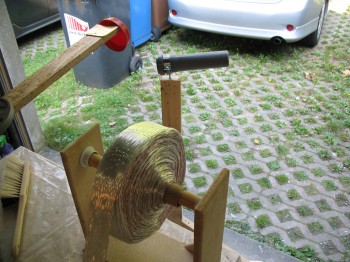
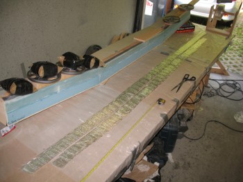
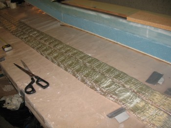
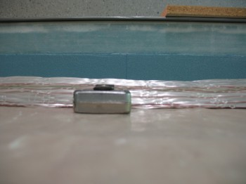
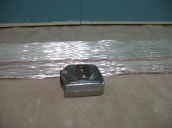
Once the bondo on the dam had cured & I had all the 3″ UNI tape cut, I thoroughly sanded the spar cap trough.
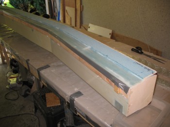
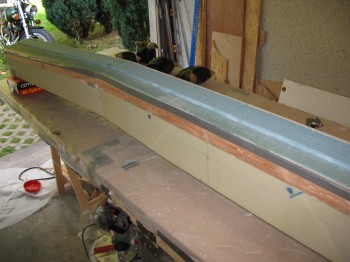
I vacuumed the spar cap trough & all the foam, and then taped up the edges of the foam lying next to the spar cap channel.
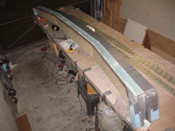
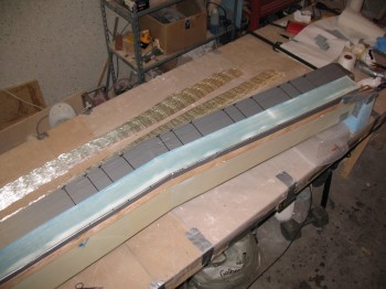
In preparation for laying up the spar cap, I measured & marked the BLs for each length of 3″ UNI tape. The top spar gets a few full length pieces, and then they start to get successively shorter in pyramid fashion. And just like with the wings, the warning in the Canard Pusher Newsletter mandates to test the cured thickness of the 3″ UNI tape being used, and add plies if it cures too thin. The test I did before I glassed the wings showed my 3″ UNI tape was too thin, so I’ve added a number of lengths of 3″ UNI glass here as spelled out in the plans change.
In wetting out the spar cap channel before glassing, I didn’t like the significant gap that was present along the outside dam edge, due to the radiused corner (although it was only about 1/8″) of the foam when the shear web got glassed. Even though it meant a little more weight, I lined that edge with a flox fillet to keep the layup even & intact, and to ensure the edge would cure strong. I also added some flox along most of the inside foam edge as well since I had it left over.
I spent hours & hours laying up the CS spar top spar cap (I want to say start to finish was literally over 10 hours).
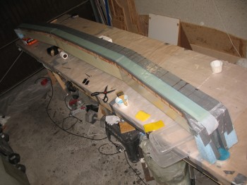
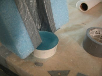
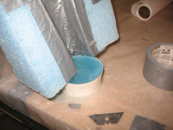
The pics don’t do it justice, and it seems like so much epoxy should NOT be wasted and should be able to be reused. I did actually reuse a ton of epoxy, but it just takes so long to prep, wet out, layup & squeegee one length of 3″ UNI tape, that by the time you get around to even attempting to reuse most of the epoxy, it has already started turning gummy & gloomy (even with a hair dryer… which I fried BTW!)
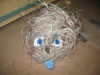
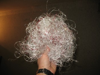
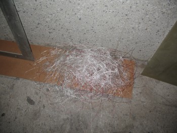
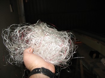
The pics below give a decent idea of the shear amount of volume of 3″ UNI tape that was used… below is just the pile of roving string & red side strings that get cut in multiple places and then carefully pulled & extracted from the 3″ UNI tape so as not disturb & completely jack up the fibers in the glass tape. The only thing that remains after these are removed is the long fibers of UNI… a good majority of them running 10 feet in length.
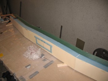
 Finally, below are some shots of the completed & peel plied upper CS spar cap.