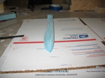
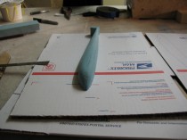
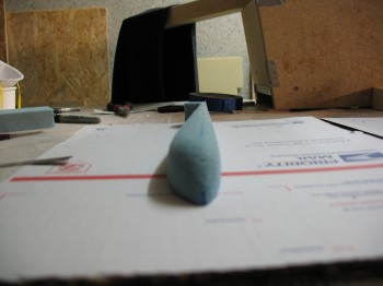
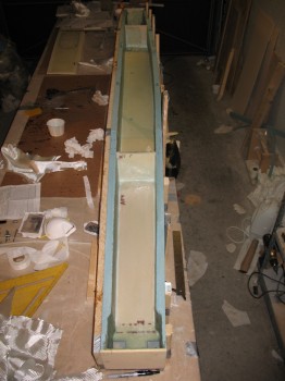
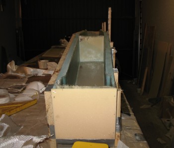
Chapter 14 – CS Spar Shear Web

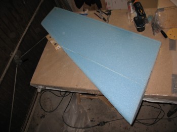
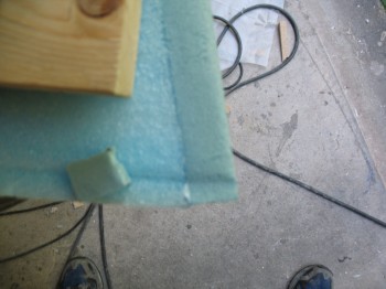
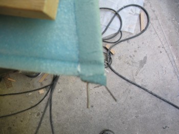
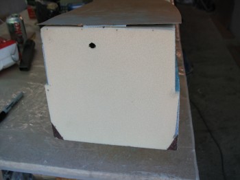
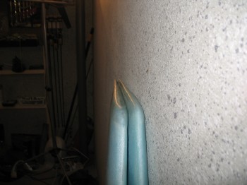
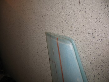
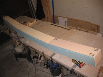
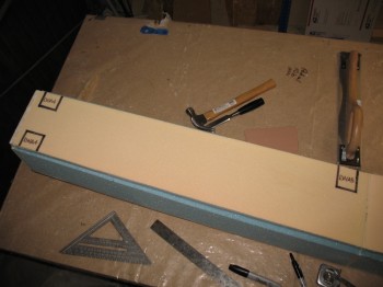
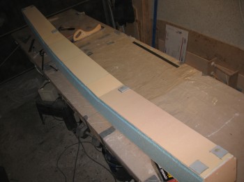
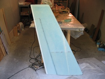
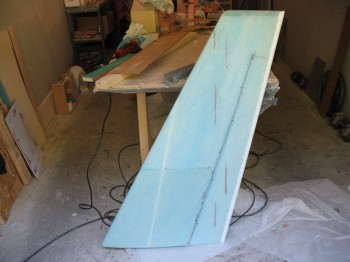
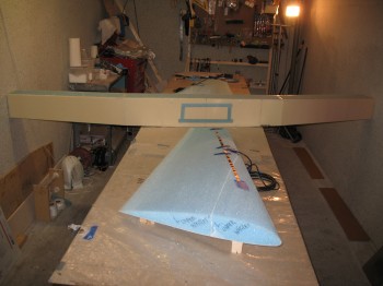
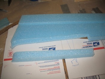
I started out today by taping the outline template of the wing BL 55.5 jut out to each end bulkhead of the CS spar.  This outline template shows the width of the wing where the wing meets the spar.  Since my CS spar is just slightly wider than the wing in certain areas, I’ll narrow the spar down just a tad in those areas before it all gets glassed.

Chap 14 - Matching spar end with wing outline

The black triangles in the corner represent the foam that gets removed per plans.  The blue marks show the area where the spar is wider than the wing.

Chap 14 - Matching spar end to wing outline

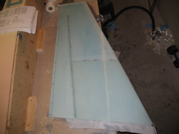
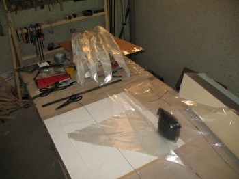
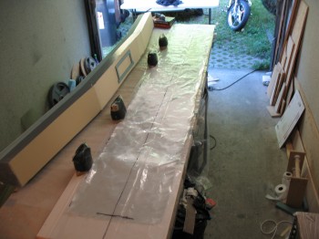
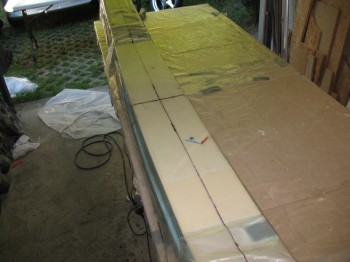
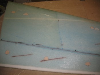
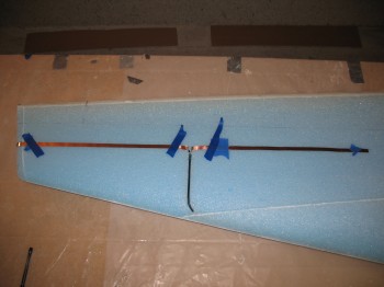
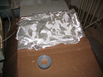
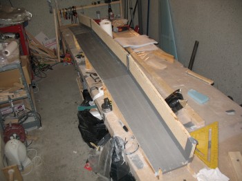
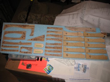
I set up the UNI glass in pre-preg for the shear web.

Chap 14 - CS spar shear webChap 14 - CS spar shear webChap 14 - CS spar shear webChap 14 - CS spar shear webChap 14 - CS spar shear webChap 14 - CS spar shear webChap 14 - CS spar shear web

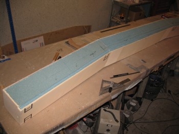
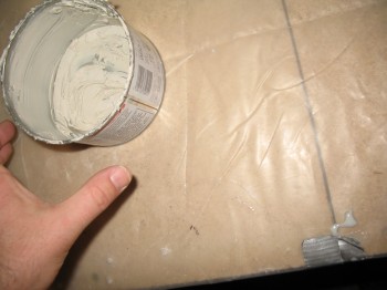
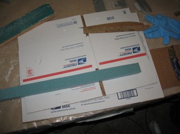
I micro’d the foam on the CS spar.

Chap 14 - CS spar shear web

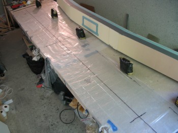
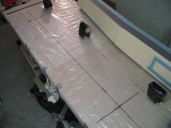
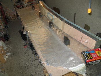
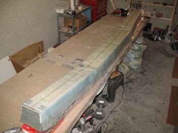
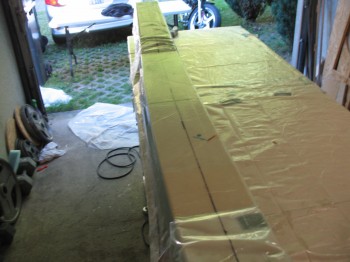
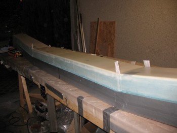
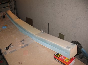
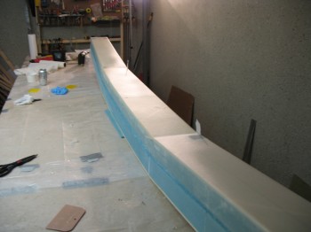
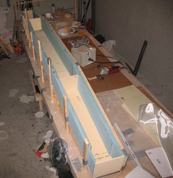
I then wet out & laid up the shear web.

Chap 14 - CS spar shear webChap 14 - CS spar shear webChap 14 - CS spar shear webChap 14 - CS spar shear webChap 14 - CS spar shear web

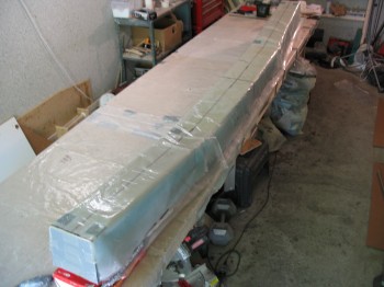
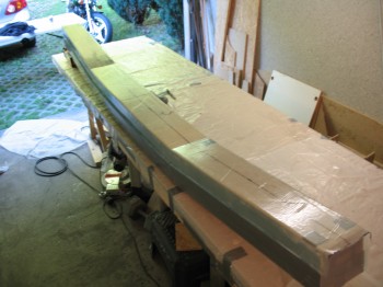
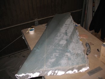
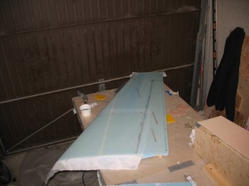
After laying up the shear web, I peel plied the glass.

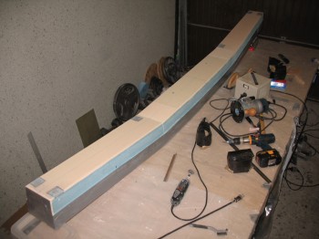
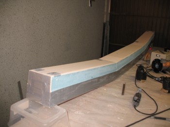
Chap 14 - CS spar shear webChap 14 - CS spar shear webChap 14 - CS spar shear webChap 14 - CS spar shear web

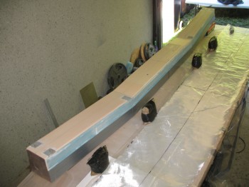
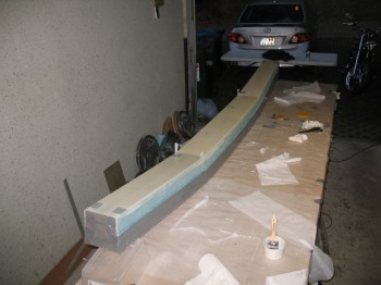
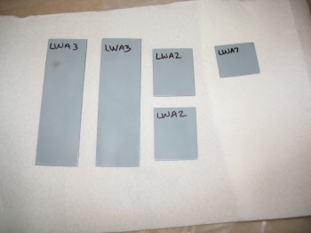
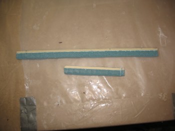
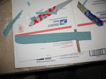
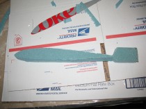
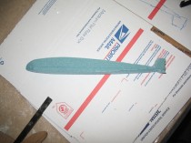
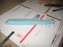
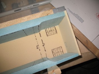
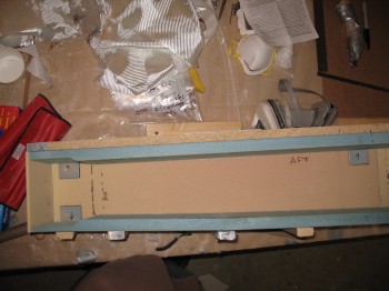
I cleaned & prepped the aluminum extrusions, lined them up & took a pic.

Chap 14 - CS spar extrusions


Chapter 14 – Bottom spar cap trough

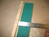
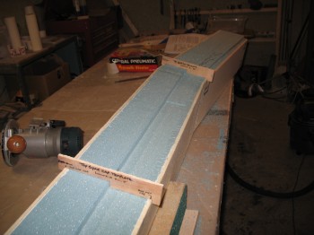
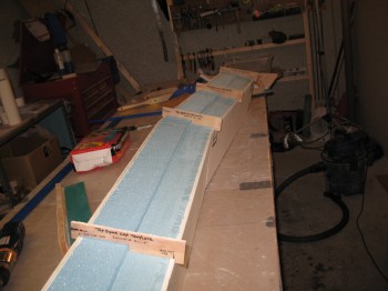
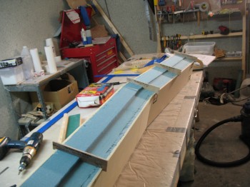
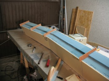
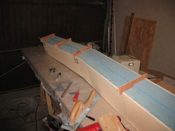
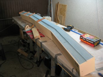
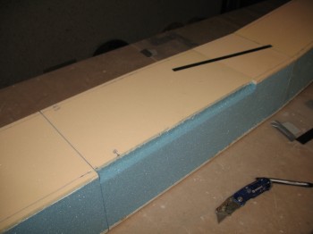
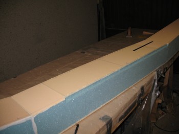
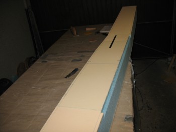
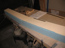
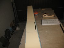
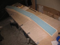
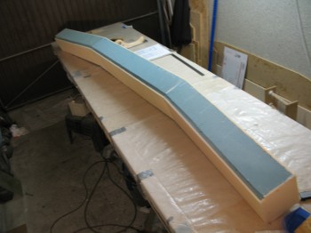
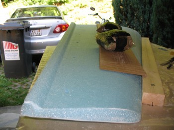
I started by routering out the bottom CS spar cap trough.  I then hand sanded to final shape using the bottom templates to ensure the depth was correct (just like the top spar cap trough).

Chap 14 - Spar cap troughChap 14 - CS spar cap troughChap 14 - Spar cap troughChap 14 - Spar cap troughChap 14 - Spar cap troughs

I used the Dremel tool to remove the 1/4″ yellow foam on the aft face of the CS spar over the interior (inside the spar box) mounted extrusions.

I cleaned up the newly exposed extrusion surfaces with Perma-Grit tools & sandpaper.

Chap 14 - Mounting extrusionsChap 14 - Mounting extrusions

I floxed in 4 each LWA4s (2 each Outboard ends) & 2 each LWA5s (1 each side Inboard). I covered the extrusions with plastic & weighed down.

IMG_0009Chap 14 - Mounting extrusions

I then taped all the foam except that which would be covered by the shear web.

Chap 14 - Mounting extrusions

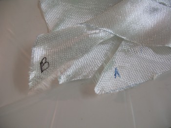
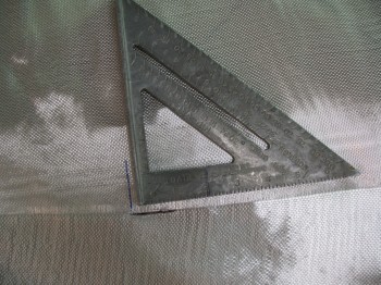
Finally, I cut the UNI as per plans (the original plans called for BID, but there was an optional mod to the layup schedule which allowed UNI to be used… saving a number of pounds by using the new UNI layup schedule).

Chap 14 - Shear web UNI


Chapter 14 – CS Spar Cap Trough

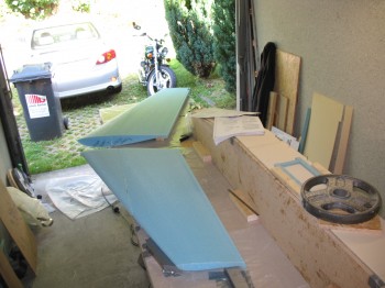
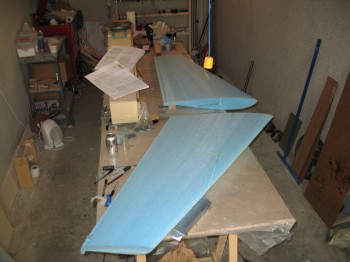
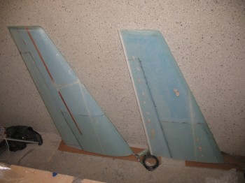
I started today by sanding both winglets.  I then cleaned them up & put them in the living room.

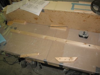
I then focused on the CS spar.  I started by making a sanding board jig to sand the spar cap troughs.  Before I used the sanding board though, I cut the majority of foam material away with my router.

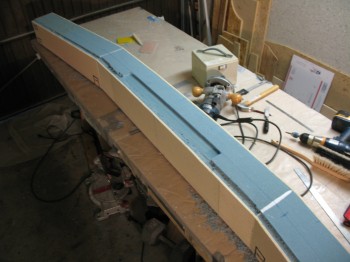
I set my router at 0.5″ depth & routed the middle 30″ of the top spar cap trough.

Chap 14 - CS spar cap trough

I then set the router to 0.4″ depth and routed the remainder of the spar cap channel.

Chap 14 - Gettin' er done!

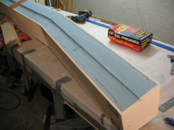
Once I got most of the material out, I used the sanding board jig and other various sanding implements to carefully get the spar cap trough to the depth outlined in the plans.

Chap 14 - CS spar cap troughChap 14 - CS spar cap trough

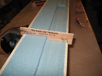
The plans have you use 4 templates to set on the top of the spar at various points (Butt Lines = “distance from center line of aircraft”).  Since the BLs are the same from the center line of the spar, they can be used on each side, and then the depth set at that point to match the template.

Chap 14 - CS spar cap troughChap 14 - CS spar cap troughChap 14 - CS spar cap troughChap 14 - CS spar cap troughChap 14 - CS spar cap troughChap 14 - CS spar cap troughChap 14 - CS spar cap trough

From a tip I picked up from David Orr (“Beagle”) and gang, I was fortunate enough to have built my wings before my spar [normally the wings are built later].  Since the end of the spar is nestled into the L-shaped crook of the wing, it makes sense that they should both be the same width . . . lest something (as in a lot of filler micro) must be added to make them match.  This of course is not the optimized way to build the wing-to-spar interfaces.

However, having been educated by Beagle, et al, that some builders in the past had dealt with issues of the spar end being significantly thicker than the wing… enough to cause some major work, rework & consternation.

I was able to ensure that the spar end & wing “root” would match by making a template of the wing root at BL 55.5 (the jut out) and match it to the end of the spar.  The end of my CS spar was, in fact, slightly thicker than my glassed wing.  I taped the BL 55.5 template to each end of the spar and marked the overage with a Sharpie.  Later I’ll sand it down to match the wing width, accounting for any glass layup thickness as well.

I then vacuumed up all the blue foam dust and called it a night.


Chapter 14 – Back to CS Spar

Today I pulled the peel ply from the Left winglet & took the TE clamps off.

The Right winglet still seemed just a tad tacky after a few hours.  But it was only a few hours after the layup & it turned really cold, so I turned on another heater to kick the heat back up over 70° for a few hours.

I rechecked the winglet later and it looked fine… I probably laid it up just slightly on the dry side, but not too bad.

I pulled the peel ply from the Right winglet and then Fien sawed both TEs & bottom edges. I then sanded the TEs… both winglets looked good.

Chap 20 - Winglet build

Chap 20 - Winglet buildChap 20 - Winglet buildChap 20 - Winglet buildChap 20 - Winglet build

Later on I removed the bondo blobs with a hammer & chisel… often just takes one sharp whack for them to come off (It was too late to use a sander at that point).

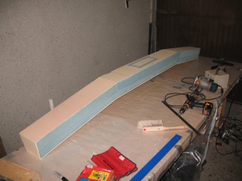
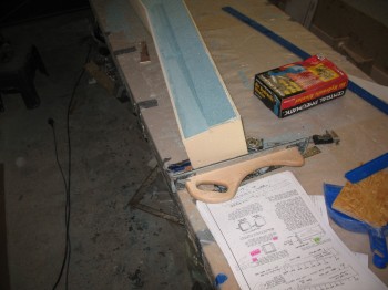
I brought the CS spar back out to the work shop and then measured & marked the lines for the spar cap trough depths.

Chap 14 - CS spar build

Chap 14 - CS spar build

I made the initial cuts for the spar cap troughs & removed the foam.

Chap 14 - CS spar buildChap 14 - CS spar buildChap 14 - CS spar build

Chap 14 - CS spar buildI marked the Butt Lines (BLs) where I will use 1 of the 4 corresponding spar cap templates.

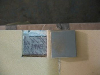
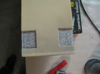
Chap 14 - CS spar buildI  then measured & marked out the locations for the aluminum extrusions.  The extrusions embedded into–and laid on top of–the foam will line up with both the extrusions glassed into the inside of the spar box and to the extrusions on the wings.

Chap 14 - CS spar buildChap 14 - CS spar buildChap 14 - CS spar buildChap 14 - CS spar build


Chapter 20 – Final Winglet Skin

Before I started on the winglets today, I ginned up some 50/50 flox/micro mix to fill in some minor gaps between the foam joints on the CS spar.

I then resanded the TE & rudder on the right winglet.

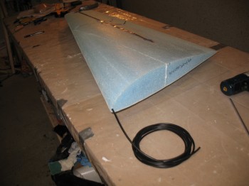
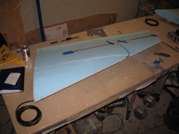
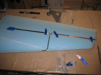
I installed the COM antennas onto the winglets . . . in the proper position this time.  I of course had to drill a long channel at the LE of each winglet and then work the antenna cable lead down through it.  It took a little bit of time, but it wasn’t that difficult.

I did have a minor issue with the Left antenna when actually sticking it onto the surface of the winglet: the last 1/4″ of copper foil ripped off as I was setting it into place!  I simple reattached it with just a hair overlapping (maybe 0.5mm) & did a continuity check.  My multi-meter rang out loud & strong so the connection was good! As long as I didn’t disturb it when laying the glass up … so it was fine.

Chap 20 - Winglet COM Antenna

Chap 20 - Winglet COM Antenna

Chap 20 - Winglet COM Antenna

Once I got everything set up, I bagged the antenna cable leads & carefully vacuumed the entire surface of each winglet.

Chap 20 - Winglet COM Antenna

Chap 20 - Winglet COM Antenna

I micro’d the foam surfaces & joints, including the antenna leads & runs, and then glassed a 2-ply UNI layup crossing at approximately 30° & the 1-ply BID reinforcement for attaching the winglet to the wing.  I also peel plied the BID layup & the LE overlap.  This was of course on one winglet at a time.

Chap 20 - Winglet Build

Again, I used my lengths of aluminum angle to clamp down the TE edges so they cured straight & even.

Chap 20 - Winglet BuildChap 20 - Winglet BuildChap 20 - Winglet BuildChap 20 - Winglet Build


Chapter 20 – Winglets + CS spar shots

Today I started out by removing the tape & the peel ply from the winglets’ edges… and of course I cleaned up a lot of peel ply gunk.

I removed the winglets from their mounts… everything looked good!

Chap 20 - Winglet Build Chap 20 - Winglet Build

Chap 20 - Winglet Build

I then cut the UNI, BID and peel ply for glassing the second/last/other side of the winglets. The pic below is just a shot of some of my leftover glass scraps.  There’s a lot of glass that gets left over and I try to reuse as much as possible.  One thing about fiberglass is that if it gets wet, with virtually anything liquid including water, sweat, or especially epoxy, it’s done for & must be thrown out.  Also, if it’s physically damaged it can’t be reused.

Glass Scraps

Another couple shots of the winglets.

Chap 20 - Winglet Build

Chap 20 - Winglet Build

I weighed down the winglets, one at a time, and cut off the fishtail & removed the peel ply from the trailing edge.  I will say one good thing on the winglets is that when the glass & epoxy are this fresh the TE peel ply comes off A LOT easier! (whew…)

Chap 20 - Winglet BuildChap 20 - Winglet BuildChap 20 - Winglet BuildChap 20 - Winglet BuildChap 20 - Winglet Build

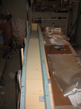
Glassing the final layups on the winglets were going to be a lot easier if I could use more of the work bench, so I removed the CS spar from its jig–since it had cured for ~3 days–and tore down the jig.

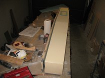
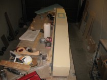
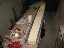
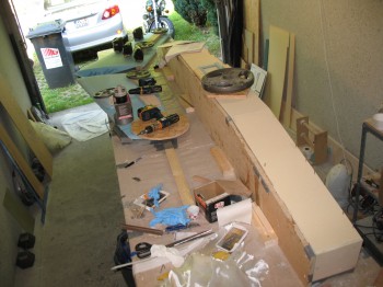
Chap 14 - CS spar removed from jigChap 14 - CS spar removed from jigChap 14 - CS spar removed from jig

Chap 14 - CS spar removed from jig

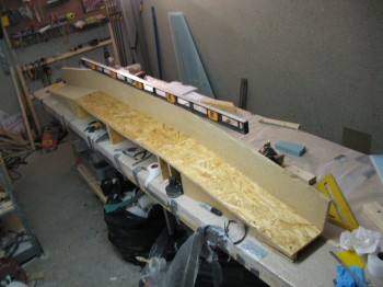
The pic above shows that the whole jig stayed fairly level during the course of the first major part of the CS spar build.

Chap 14 - CS spar jig teardownChap 14 - CS spar jig teardown

After tearing down the jig & getting all the jig pieces removed, I did a fairly thorough cleanup.

I remounted the winglets Inboard side up (bare blue foam), sanded down the LE & Dremeled the dead micro from the winglets.

Chap 20 - Winglet BuildChap 20 - Winglet Build

I refilled my epoxy jug & hardener bottles . . . apparently all this building is gettin’ it done since I only have about 2 gallons of epoxy left.

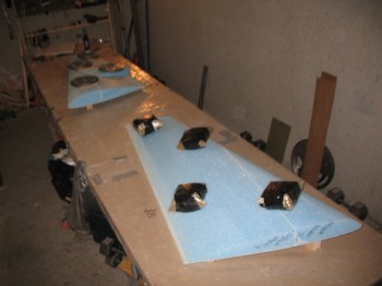
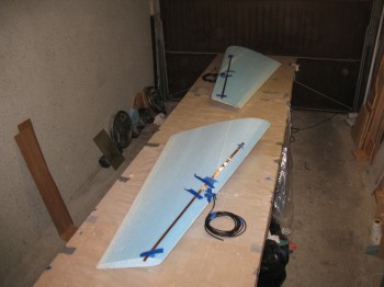
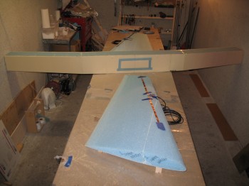
After getting the consumables reloaded, I made 2 COM antennas with 17 ft leads.  I then took them out to the workshop & mocked them up on the winglets (albeit they are not in the correct location on the winglets in these pics).

Chap 20 - Winglet BuildChap 20 - Winglet BuildChap 20 - Winglet Build


Chapter 20 – Outside winglet skin

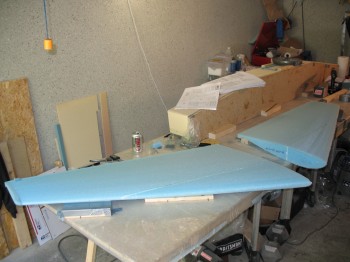
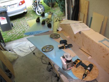
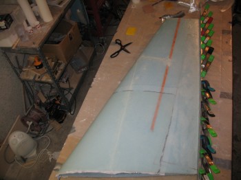
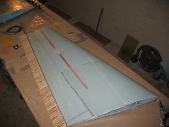
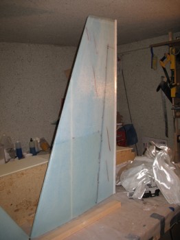
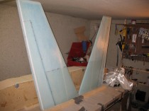
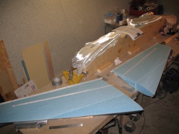
Today I cleared some area off of the workbench next to the curing CS spar to set up the mounting boards for the Left & Right Upper Winglets.  I’ll be skinning the outside of the winglets by glassing 2-plies of UNI crossing each other at about 30° (or 60° I guess, depending on how you look at it!).

Once I have the mounting boards screwed down to the table, I put bits of duct tape over the screws so they don’t inadvertently get epoxied or floxed into place.  The mounting boards do 2 things:

1) They stabilize the winglets, making them much easier to glass.

2) With the winglets secured in place, they won’t warp as the glass cures on the one side of the winglet.  Making for a straighter, truer winglet.
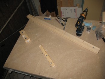
Chap 20 - Upper winglets

Chap 20 - Upper winglets

Chap 20 - Upper wingletsChap 20 - Upper winglets

Chap 20 - Upper winglets

Chap 20 - Upper winglets

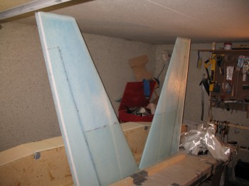
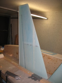
Once I got the proper spacing down so the winglets laid true on the wood mounts, I floxed the winglets to the mounts by adding little dabs of flox along the wood surfaces & laid the winglets on the mounts (Before I removed the mocked up winglets, I marked the edge so I knew where to place them back down).   After I mounted the winglets to the floxed boards, I weighed them down to ensure a good seal.
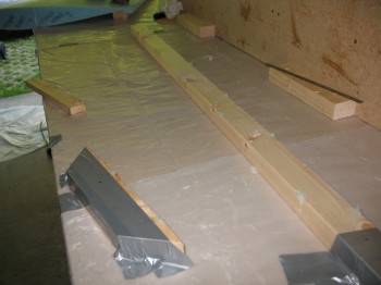
Chap 20 - Upper winglets

Chap 20 - Upper winglets

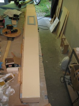
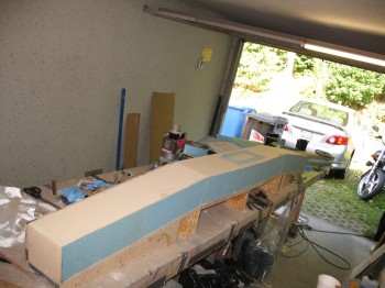
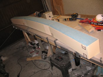
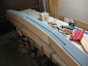
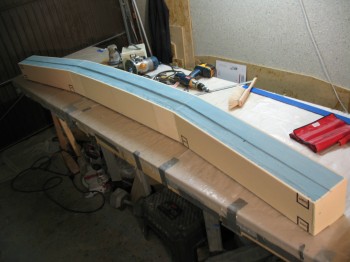
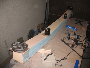
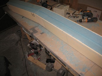
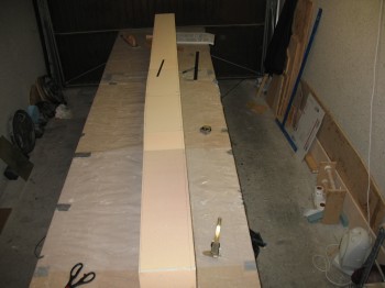
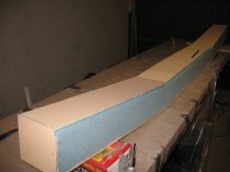
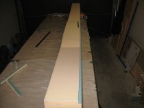
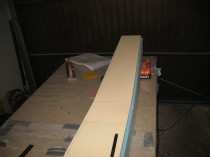
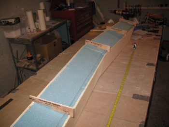
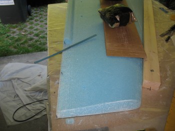
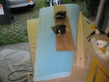
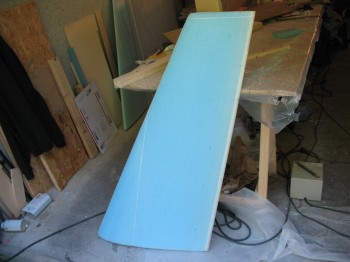
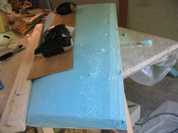
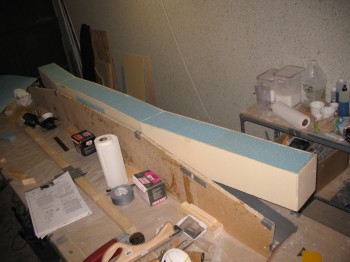
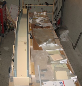
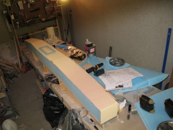
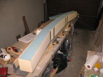
Below are some good shots of the curing CS Spar.  I had weights all along the top of the spar for some 30+ hours to ensure a good seal between the front spar walls (top of jig as it sits here) & the spar box.  I removed the weights to keep them from somehow hurling themselves off the spar and onto–thus smashing into pieces–the unsuspecting TE edge of an innocent winglet (yep, with me it could happen…took no chances!).  The blue foam rectangular outline on top is to protect ME against the tacks protruding through the foam that hold the peel ply to the 5″ x 14″ center oval access that gets cut out later.
Chap 20 - Upper wingletsChap 20 - Upper winglets

Chap 14 - CS Spar...2-3 day cure

Chap 14 - CS spar...2-3 day cure

With the winglets weighed down & curing onto their respective mounts, I prepped for the upcoming layups.  I charged my Dritz scissors and soaked/cleaned some squeegees.

Also, my decorative top cap on the Left winglet was lacking at the tail end, so I cut & shaped a small foam wedge to add to the TE.  I micro’d it & held it in place with a thin nail.
Chap 20 - Upper wingletsChap 20 - Upper wingletsChap 20 - Upper winglets

I then went back to prepping for the upcoming layups.

I went to my cutting table in the downstairs shop to cut 2 pieces of 38″ x 54″ UNI and 2 pieces of 38″ x 64″ UNI.

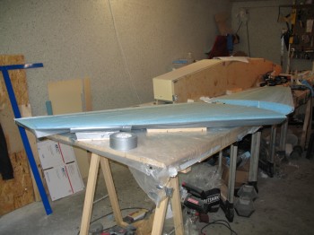
I left the glass in the downstairs shop.  Since the flox on the winglet mounts had cured, I went back the garage to prep the winglets’ outside surfaces for glass.  I pulled all the weights off and then used the Dremel tool to remove all the dead micro in the seams & joints.  I then carefully sanded the leading edges smooth.  I also marked up where the rudders would be going (like the ailerons getting cut out of the wing structure, the rudders also simply get cut out of the glassed structure of the winglet).
Chap 20 - Upper winglets

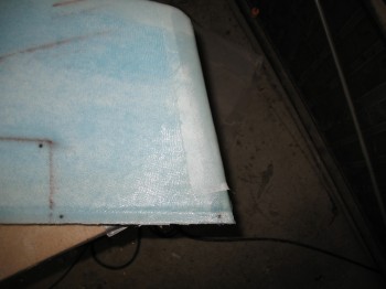
Obviously the winglets get glassed to the wing, and just like the wing, they get a reinforcement piece of BID glassed onto the surface area that will get glassed to the wing. I made a cardboard template of the area where the BID piece will go.  After I cut the 2 pieces of BID–1 for each winglet–I then used the same template to cut the peel ply that would cover the BID.

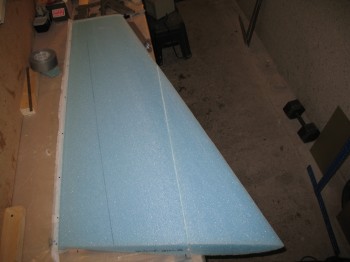
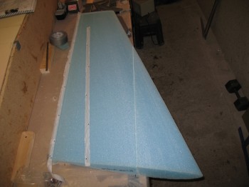
I vacuumed the entire top surfaces of both winglets & then taped the LE halfway along the entire length.  I then tacked on a 1″ piece of peel ply down the TE trough that runs the TE length of the winglet, top to bottom.  Before I could do this though, I had to physically create that trough on both upper winglet caps that I added.
Chap 20 - Upper winglets

Chap 20 - Upper winglets

I also threw in peel ply down the center of the seam of where the rudder will get cut out of the winglet, since the foam & glass inside there will get removed with a glass-to-glass layup occurring where the peel ply gets removed (at least along a good portion of the peel ply… I’ll still have to prep some glass that has only foam attached to it).
Chap 20 - Upper winglets

Chap 20 - Upper winglets

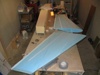
Ready to do some layups, I grabbed my glass from downstairs & double checked my winglets’ surfaces.  As you can see in the pic above & below, I added angle marks to allow me to get my glass laid up in the correct orientation.
Chap 20 - Upper winglets

I dry micro’d the channels (where I had cut the dead glass out) & microslurried the fields.  I then started glassing like the wind!
Chap 20 - Upper winglets

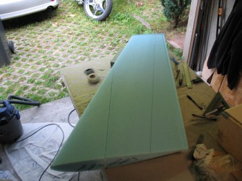
Above pics shows second ply of UNI getting glassed on.  Below is the finished Left winglet.
Chap 20 - Upper wingletsChap 20 - Upper wingletsChap 20 - Upper wingletsChap 20 - Upper winglets

The pic below shows my last minute top-cap add-on/repair result.
Chap 20 - Upper winglets

After the layup had cured for a little bit, I removed the tape from the LE.  The peel ply was having a hard time wrapping around the sharp bend of the LE & top, so I coaxed it a little by taping the dryer part of the peel ply and then wrapping it around the winglet LE & attaching it to the dry foam underneath.
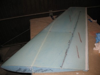
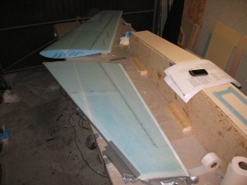
Chap 20 - Upper wingletsChap 20 - Upper winglets

After the winglets had cured for quite a while, but while still tacky, I micro’d in the TE trough with dry micro.

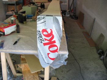
 

Chapter 20 – Upper Winglets

Today, as the CS spar cures, I started by spending around 2 hours at the Ramstein base wood hobby shop.  I finished cutting a bunch of templates, jigs & parts–mainly for the canard build.

Chap 10 - Canard templates, jigs & parts

I also bought stuff to restock the basic composite working supplies: duct tape, tacks, etc.

I then switched gears to focus on Chapter 20, the Upper Winglets.  I’ll knock these out as the CS spar cures completely for a few days.

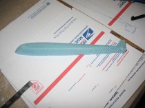
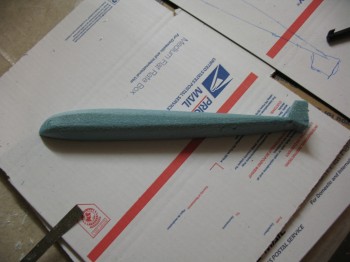
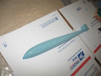
The first thing I did was work on the cosmetics of the Long-EZ’s upper winglets.  I have noticed a lot of beautiful Long-EZ’s that seemed like the very top of each winglet was simply hacked off and stolen…. very square.  I would like my winglets to have a rounded look, swept back from the front and smooth all the away around.  So that, my dear friends, is what I worked on today.

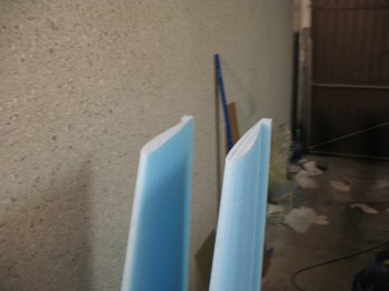
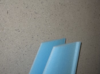
I started out with a scrap strip of blue PVC foam.  Now blue PVC foam is not known for its ease of shaping, but I wanted something that could not be easily damaged with one swipe of the sanding block.  I slowly shaped the rounded blended top cap for the winglet.

Chap 20 - Round-shaped winglet top

Chap 20 - Round-shaped Winglet top

I double-checked a ton, but finally got a good shape I could work with.

Chap 20 - Round-shaped Winglet top

Chap 20 - Round-shaped Winglet top

I refined just a tad more to get the finish & shape I was looking for….

Chap 20 - Round-shaped Winglet top

Chap 20 - Round-shaped Winglet topChap 20 - Round-shaped Winglet top

And then, just to try out something different, I made the other side from the more porous blue wing foam.

Chap 20 - Round-shaped Winglet top

I continued to mock them up on the tops of the winglets, and then continued to refine the shape of the top caps.

Chap 20 - Round-shaped Winglet topChap 20 - Round-shaped Winglet topChap 20 - Round-shaped Winglet top

Chap 20 - Round-shaped Winglet top

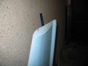
Once I was happy with the shape of each side, I micro’d the new tops onto the winglets & held them in place with nails.

Chap 20 - Round-shaped Winglet top

Chap 20 - Round-shaped Winglet top

Chap 20 - Round-shaped Winglet top


Chapter 14 – CS spar cable conduit mod

Today I measured out and looked at different wiring & conduit options.  I decided to go with Marc Zeitlin’s method (I guess I should have checked my notes before yesterday’s post!).

I have to apologize ahead of time because I swore I took pictures of today’s progress, but currently I can’t find them.  I will keep looking though.  So, on with the build log:

I cut a 1″ hole half-way through the foam of the end bulkheads from the inside of the spar box.  I’ll cut a 7/8″ hole later on from the outside, going into & more closely matching the Inside Diameter of the 1″ tube on the inside of the bulkhead.  As I said before, the 1″ tube will simply run from the outside bulkhead to the interior bulkhead to serve as a conduit to get all the wing electrical wires and antenna cables cleanly from the wing, into the CS spar to be routed from there throughout the fuselage.  This will be on both sides of the CS spar, so one conduit on each side.  The hole I cut (drilled) on each end bulkhead is just above the bottom aluminum extrusion to keep as close to the bottom of spar & shear web as possible, but still allow clearance for the wing bolt.

I then drilled holes in the aft bottom corner of both interior bulkheads, opposite the exterior bulkheads.  I cut the ~1″ (technically 25mm) plastic tubing at a slight angle on each end to fit cleanly on both sides & into the recessed holes on the interior side of the Outboard bulkhead and the vice versa on the Inboard bulkhead.

I used a 3/16″ x 5″ scrap piece of blue foam to prop up the middle of the plastic tube–since it was suspended between each bulkhead–to cut on down on any possible vibration tendencies, rattling, etc.  I used micro to attach the blue foam block to the interior back wall of the spar.

I then micro’d both ends of the plastic tube in place into each of the recessed holes on the bulkheads (one tube on each side of CS spar).  I also micro’d the center of the tube to the blue foam block.  I then glassed a 1-ply BID 4″ x 8″ layup over the pipe & blue foam block.

Ok… Although I am both a convert & believer of Burt, I guess sometimes I doubt a little if something is as strong as it is… even though it would probably far exceed my expectations.  Thus was the case with attaching the front foam pieces to the rest of the spar box (remember, this is the “top” as it sits in the jig).  I measured out where the interior bulkheads would abut the interior front spar face, marked it and sanded it down for a future 1-ply BID corner tape just for a little reinforcement (mod… not per plans).  Not that I was doubting Burt in his design, I was merely “helping” him out . . . haha!

I then (per plans) prepped the front spar pieces for attachment to the rest of the spar box. I removed more peel ply boogers & sanded down some areas need extra attention.

I removed the front wood jig supports, thoroughly vacuumed the inside of the spar box, and wiped down the front (soon-to-be-mounted) spar wall pieces.

I taped the edges of any foam that would subject to any type of micro slop & mess.  I then micro’d, nailed and weighed down the front (yellow foam) spar wall pieces (top as far as the jig is set) to the rest of the spar box.

Clock start time for my “2-3 day cure time” was 0100 Saturday morning.

I checked the micro’d pieces ~2 hours later & put some more nails to hold some areas better into place & aligned.  I also removed a bunch of tape & gummy micro.
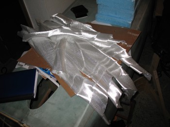


Chapter 14 – CS Spar…glass in the box

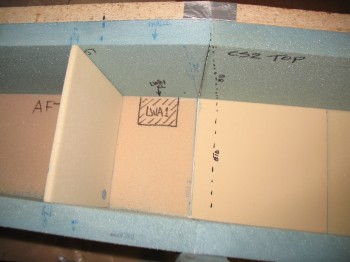
I marked up where the Outboard aluminum extrusions (LWA1) will go (on the inside of the spar box).
Chap 14 - CS spar build

Chap 14 - CS Spar BuildI then marked  up where the Inboard aluminum extrusions (LWA1) will go (on the inside of the spar box).
Chap 14 - CS Spar BuildChap 14 - CS Spar Build

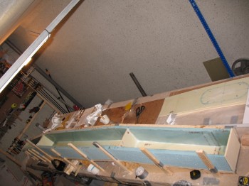
Below is a shot of all the aluminum extrusions on the Right-hand side of the CS spar.  The extrusions will sit at the back of spar box & align with the aluminum extrusions on the Right wing.  A 5/8″ hole will get drilled through all the extrusions at each of the 3 hard points, and 3 large 5/8″ wing bolts will hold each wing on.

Chap 14 - CS Spar Build

I pulled the 1″ peel ply off the CS spar front face pieces (yellow foam/CS4) & then cut the edges smooth with the “Fein” saw.

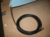
Another mod I found somewhere, I don’t remember right now (It may have been a Marc Zeitlin or Vance Atkinson noted mod from the Cozy world … but don’t quote me), is installing a permanent plastic conduit between the outer end bulkhead and the interior bulkhead on each side, about 1″ round in diameter, as an electrical wire/antenna cable conduit.  So I cut & played around with some nice, thin lightweight conduit I picked up at the Aviation Dept at Praktiker (German Lowes).  You can see a bit of the grey thin-walled conduit–much thinner than PVC pipe–in the pic below at the bottom.

Chap 14 - CS Spar Build

I made 4 each ~4-pound sandbags to use during the remaining build projects.

I cut BID for the spar box & individual pieces for all 4 bulkheads. I then sanded down the joints between middle blue foam pieces & the outer foam pieces to align them.

I vacuumed the inside of the spar & then taped off the front of the blue PVC foam.

I spread dry micro as a fillet in the corners & microslurry on the large foam “fields.”

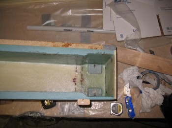
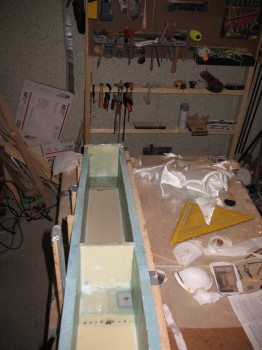
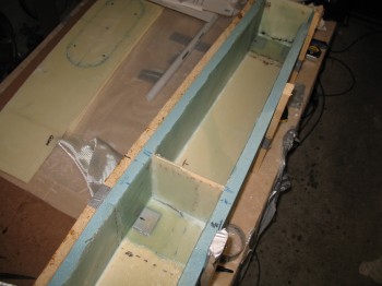
I then glassed Layup #2, which is the whole interior of the spar box (technically 3 individual compartments with the 2 interior bulkheads) with 1-ply of BID.

I glassed Layup #3 which is a staggered 3-plies of UNI over the interior aluminum extrusions.  That then gets covered with 1-ply of BID.

I then glassed Layup #4 which is essentially the same as Layup #3, but since the aluminum extrusions are opposite sides of the back foam wall (top & bottom when on the plane, front & back as it lies on the jig), the 3-plies of UNI cover both extrusions with a 1-ply of BID covering as the last ply for reinforcement.

Chap 14 - CS Spar Build

Chap 14 - CS Spar BuildChap 14 - CS Spar BuildChap 14 - CS Spar Build

Chap 14 - CS Spar Build

Chap 14 - CS Spar Build