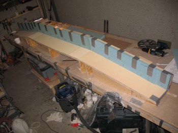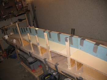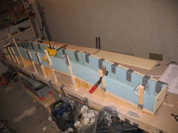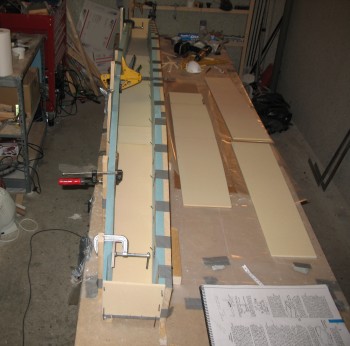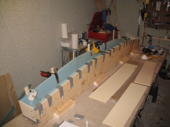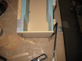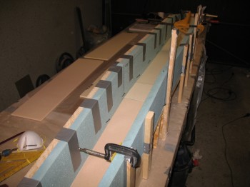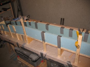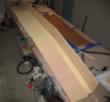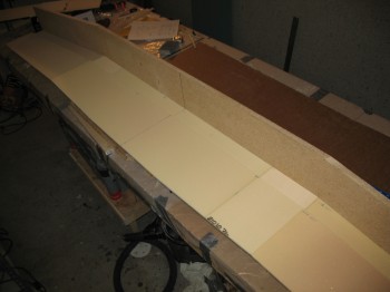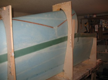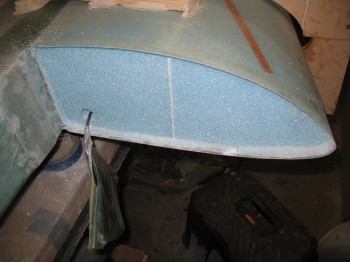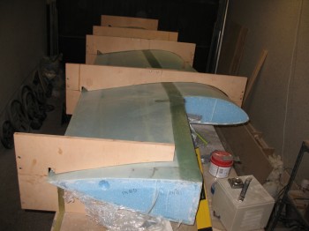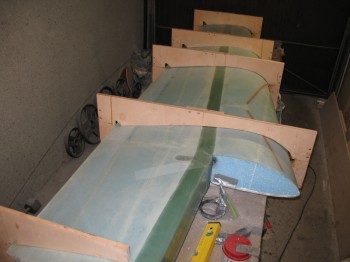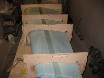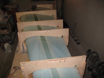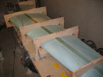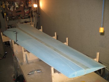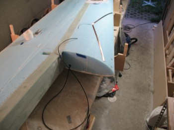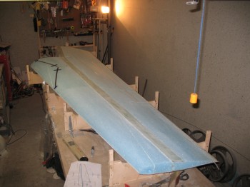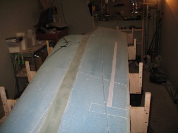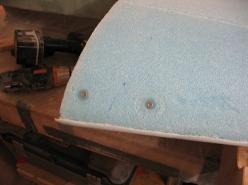
Chapter 14 – CS Spar front face layups

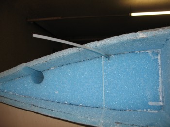
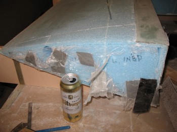
A significant mod that I’m making concerning the CS Spar is that I’m running the rudder cable conduits through the interior sidewalls of the fuselage & then through the front & back wall of the CS spar.  Note, this is not an afterthought action, so I won’t just be merely drilling holes through the inside & outside glass surfaces of each spar face.  What I will be doing, after much consultation with the old guard, is carefully separating the glass fibers so they stay intact and are simply rerouted about 0.04″ to 0.13″ to each side of the hole to make room for a small 3/16″ hole on the exterior spar walls, and a 1/4″ hole on the interior walls.  Inside the spar I will run a phenolic conduit for the Nylaflow rudder cable conduit to run through.  Thus, to cite an overused reference, there will be no glass harmed in the making of this CS spar.

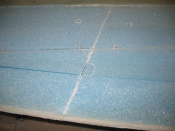
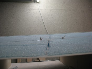
That being said, I forgot about the 0.5″ wedge that gets cut off the top front & bottom edge of the spar, so I set up the 2 holes for the rudder cable conduit 0.3″ from the edge, but I set them up incorrectly on the original “un-wedged” edge of the front spar face.  No worries since this all gets removed when I sand down & remove the 0.5″ angle off the front corner edges.  Of course I realized this after I had laid up the BID glass!

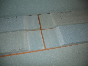
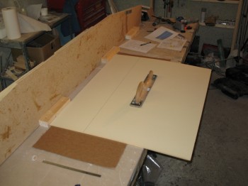
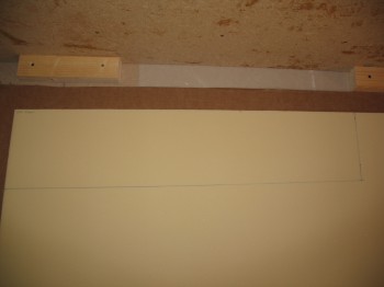
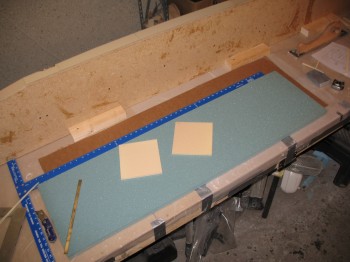
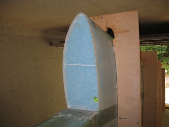
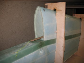
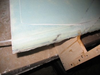
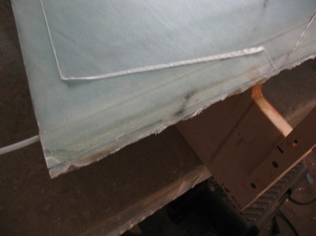
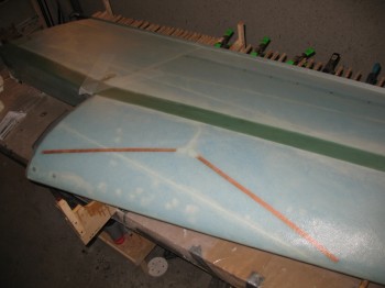
One other slight change I made was more out of curiosity than any build mod.  I tacked a piece of peel ply under the BID on the very front spar piece where the 5″ x 14″ oval access hole will be cut out.  The plans don’t have you peel ply this, but I went 5/16″ beyond the edge of the hole since after the hole foam/glass gets removed, 0.25″ of the foam gets removed & the glass on the edge of the hole prepped so the outer front face glass will have a good glass-to-glass bond when that layup is complete (i.e. inside spar glass bonded to outside spar glass).
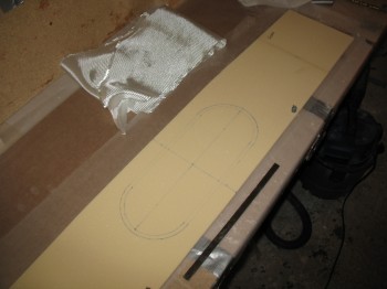
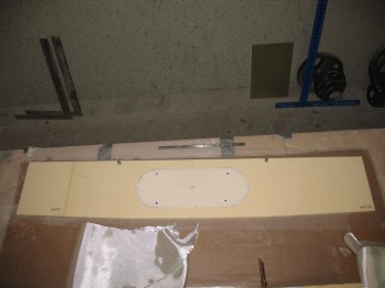
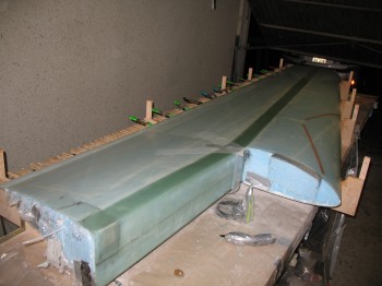
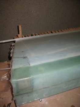
Chap 14 - CS spar...front spar pieceChap 14 - CS spar...front spar piece

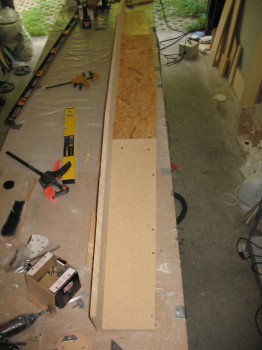
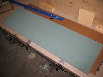
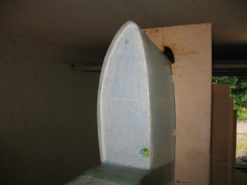
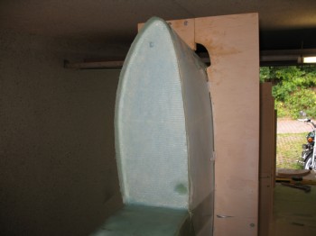
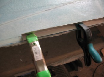
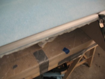
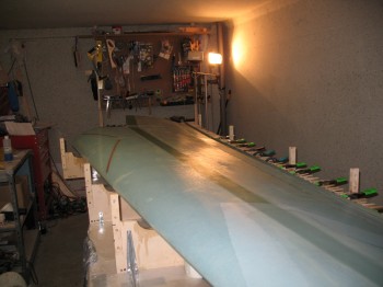
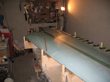
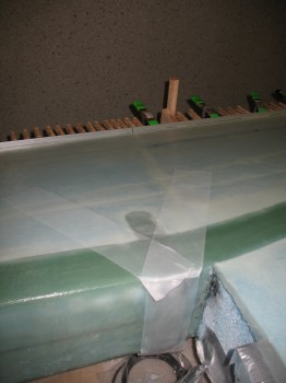
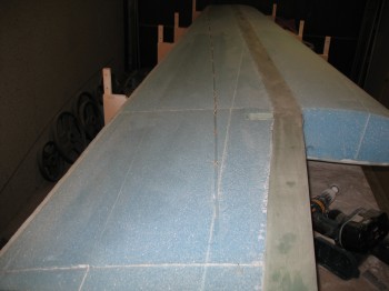
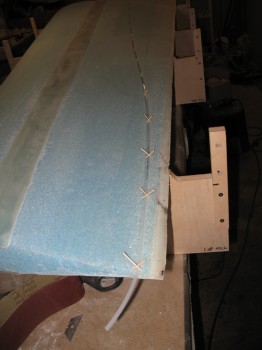
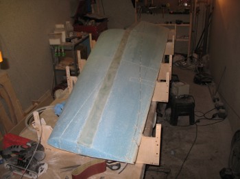
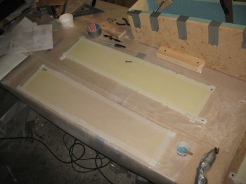
I prepped the foam for the spar’s front center face (interior side) with microslurry, then glassed the 1-ply BID layup.  I then peel plied 1″ along the edges, since the edges will be micro’d to the blue foam edges at the front (currently top as jig is configured) of the spar box.

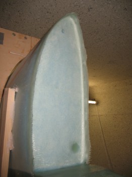
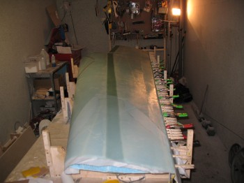
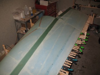
I then did the same thing with both the Left side & Right side spar front face pieces: microslurried then glassed a 1-ply BID layup with 1″ peel ply around the edges.

Again, these layups were all on the interior side of the pieces that will make up the front of the spar.  The exterior front of the spar is pretty much the last thing that gets glassed on the spar (actually the 2 square end bulkheads are the last to get glassed, but who really counts those…?!)
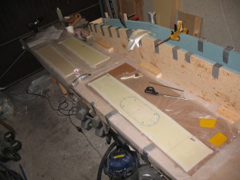
Chap 14 - CS spar...front spar pieceChap 14 - CS spar...front spar piece

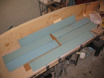
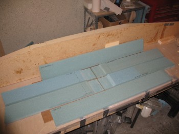
After the front face pieces were glassed, I marked the foam inside the spar box with a Sharpie near the interior 2 bulkheads where the respective BID & UNI layups will be glassed.

I also marked the positions where the rudder cable conduit will exit on the aft CS spar wall (10.2″ L & R of CL & 1.8″ below the inside top wall of spar).


Chap 14 – CS Spar prep night

Tonight was a significant, but light, night build wise.

I climbed under the fuselage & took measurements for the rear CS spar mount & firewall area.  One specific measurement I was looking for was the difference in the placement of my 4 Spruce hard points/inserts, since my fuselage is slightly wider & the side walls exit the fire wall going forward at a slightly steeper angle than stock.  These 4 Spruce hard points will get embedded into the foam & become part of the CS spar’s upper & lower wall.  Then both fuselage & engine mount arms will be bolted to the CS spar via these wood hard points.

I cut the BID glass for the INSIDE of the 3 pieces that make up the front CS spar wall.

I cut the UNI & BID for Step #4, which is where the aluminum extrusions for the CS spar get installed.

I took the rest of the night off.

Chapter 14 – All CS Spar

Well, the first major build stage for both wings is complete.  For now I’ll be focusing on the Centersection (CS) Spar, with a brief intermission for working on the upper winglets.  This intermission will be brought to us while the 3 front spar wall pieces cure (2-3 days as per plans) after they are micro’d in place on the spar box.

I finished cutting the top & bottom sides (remember, front & back in the jig) of the blue PVC foam.

Chap 14 - CS spar build

I then routered out the end channels on the blue PVC foam to leave a 0.7″ wide tab for the top & a 0.4″ wide tab on the bottom.

Chap 14 - CS spar build

Chap 14 - CS spar build

I then had to micro some smaller pieces together (blue foam) to make up the full length pieces that would be assembled & make up the top & bottom walls (front & back on jig) of the spar.

Chap 14 - CS spar build

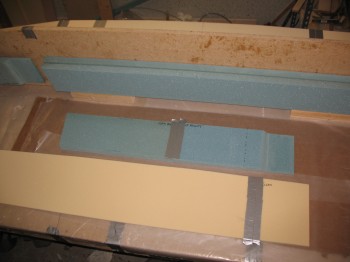
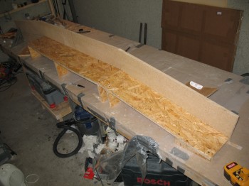
I then micro’d 3 pieces (yellow foam) together to make up the back wall (lying on the flat center shelf) & then micro’d the Left & Right outer pieces (that lie flat but slope down) that make up the entire back wall of the spar.  Again, these foam pieces cover the entire duct taped shelf.

Chap 14 - CS spar build

Chap 14 - CS spar build

I then micro’d the the 3 blue PVC top spar pieces (back jig wall) both to each other & down onto the back wall (yellow foam lying flat on the shelf).  I held the blue foam into place with nails driven at an angle into the yellow foam & strapped it to the back wall with duct tape.

Chap 14 - CS spar build

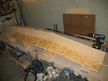
Most builders will recognize the scrap wood I used for the jig’s front wall support tabs as the same scrap that is used to protect foam shipments from Aircraft Spruce.  I screwed (not bondo’d!) these wood support tabs to the front of the jig to micro the bottom center spar piece in place (bottom spar = front jig).  I then added more front wood jig supports to micro the Left & Right side bottom spar blue foam pieces into place so that a 3-sided channel consisting of the top, back and bottom spar walls was created.  I used finish nails, duct tape & clamps to hold the bottom PVC foam spar wall in place.

Chap 14 - CS spar build

Chap 14 - CS spar build

I then micro’d on the CS spar’s yellow foam end caps–actually classified as bulkheads–with nails as well.

Chap 14 - CS spar build

Chap 14 - CS spar build

I double checked all the bonds, ensured the surfaces were all mated well together & removed all the excess micro.

Chap 14 - CS spar build

Chap 14 - CS spar build

Chap 14 - CS spar build

Chap 14 - CS spar build

With the initial stages of the spar box assembled & curing, I called it a night.


Chap 19 – Left wing & Chap 14 – CS spar

Today I finished the current build of the Left wing.  I placed the wing on the table bottom up. I knocked the jigs off the wings & cleaned up the bondo.

Chap 19 - Left wing complete/moving to storageI took the wing outside & placed on the fold out work table, and then sanded all the bondo off the wing.
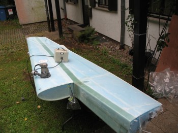
Chap 19 - Sanding bondo off Left wingAfter I finished sanding the bondo off the wing & then cleaned off the wing (the rain helped with that!).  I then stored the wing in my environmentally controlled storage facility (ha! yes, my dining room . . .)
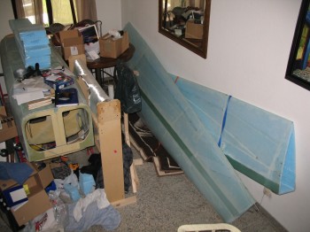
Chap 19 - Environmental controlled storage facility! HA!Now, let me talk a little bit about some housekeeping items.  Literally.  Of course in the pic above, it’s a bit messy.  Well, since I’m on quite the accelerated schedule–to be able to use all the epoxy I bought en mass–I had to choose between glassin’ & sandin’ versus keeping everything else ship-shape.  Essentially, it comes down to my prioritizing the build over pretty much everything else for a few months.
The other item is an issue for the locale in which I am building: trash.  Building this airplane, especially since it’s composite, produces A LOT of trash.  Unfortunately for a plane builder, Germany is incredibly strict about its trash.  Germany has you identify trash into five (5) different categories.  Their curbside trash bins are SMALL here and they only pick up each kind of trash about every other week.  Thus, I have a lot of build trash that piles up, and not much place to put it.  So I get what I can out (often, if the trash isn’t sorted just right, they won’t touch it) and then continue to build.  Eventually, all the trash will get out since I will stop building in mid-October for at least 6 months.  Luckily, fiberglass & used peel ply doesn’t rot!

Ok, back to airplane building!

I lined up the troops one last time for some photos after their long hard slog.  Although not an exact perfect fit, I was very impressed with how well the wing jigs worked.  Brilliant idea & brilliant design in my opinion.

Chap 19 - Wing jigs...after the great battle!

Standing tall one last time!

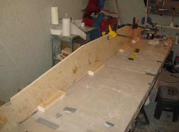
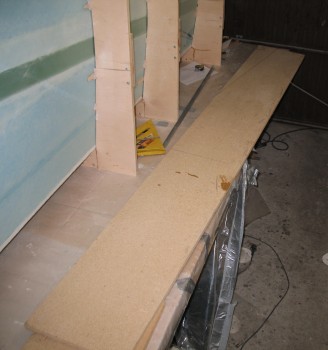
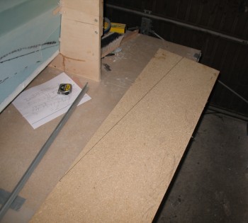
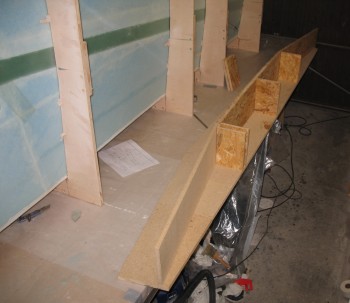
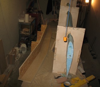
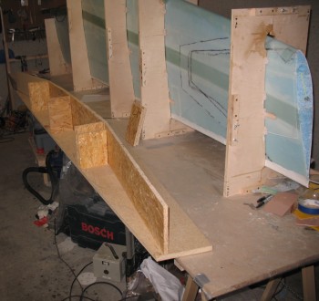
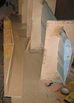
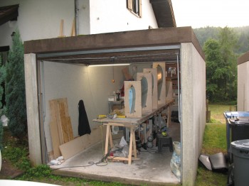
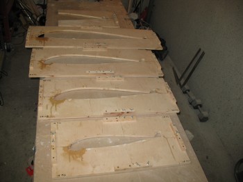
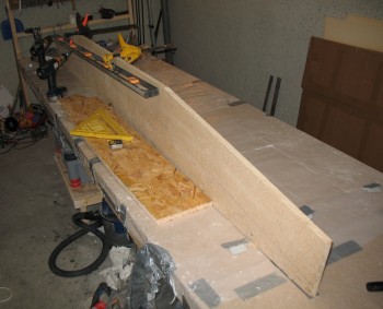
Afterwards, I started assembling the jig for the Centersection Spar.  I know many may be aghast at my co-mingling of different types of wood, but I had it on hand and it will all get trashed (again, at some point) eventually.  I actually shipped the long pieces of particle board here from the States specifically for this jig.

Chap 14 - CS spar jig construction

Chap 14 - CS spar jig construction

Chap 14 - CS spar jig construction

Chap 14 - CS spar jig construction

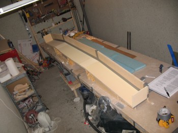
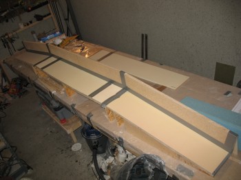
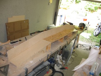
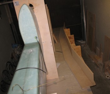
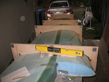
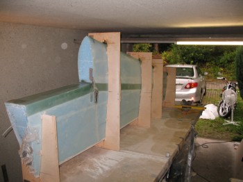
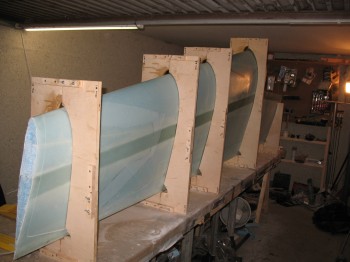
The CS Spar gets built on this jig as if the airplane were flying straight up into the air.  The backboard is actually the top.  The shelf that is level in the middle & curves downward on each end is the back of the CS spar.

Chap 14 - CS spar jig construction

Chap 14 - CS spar jig constructionChap 14 - CS spar jig constructionSince foam gets micro’d on the surface of the shelf… and we prefer NOT to leave any foam chunks of our CS spar left attached to the wood, I covered the entire shelf assembly with duct tape (maybe the differences in wood types was getting to me a little as well).
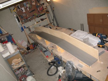
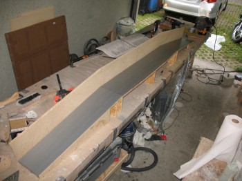
Chap 14 - CS spar jig constructionChap 14 - CS spar jig constructionI then took inventory of the foam & ensured it was in good shape/undamaged.
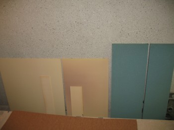
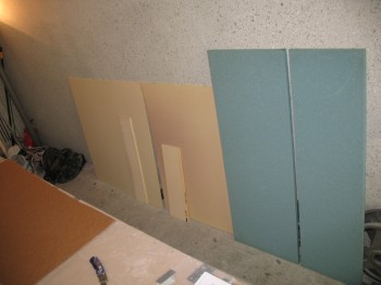
Chap 14 - CS spar foamChap 14 - CS spar foamYou’ll notice (if you’re a builder) that I’m using the slightly denser 3# blue PVC foam vs the 2# polyurethane.  Both are fuel resistant, unlike wing foam which dissolves rapidly in fuel & other hydrocarbon-type liquids.  Polyurethane is much easier to shape, but the dust is horrible and the chance of delaminations are much higher on the polyurethane.  I generally use wood working tools on the foam anyway, so the blue should be ok to work with.
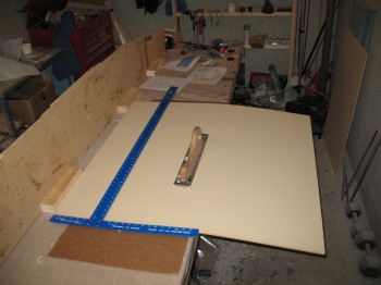
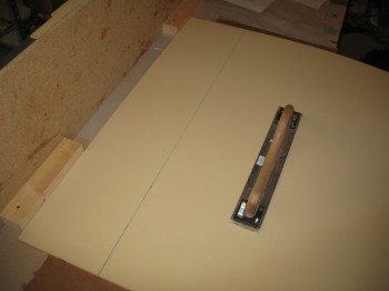
I started by cutting the 3 large front pieces (on the jig, the front is situated on top).

Chap 14 - CS spar build

Chap 14 - CS spar build

Chap 14 - CS spar build

Chap 14 - CS spar build

Once I got the front pieces cut, I cut the identical back pieces (which are on the bottom shelf of the jig as it gets built).  The pics below have both the front & back pieces, they’re just staggered.

Chap 14 - CS spar build

Chap 14 - CS spar build

Then I began to cut the top & bottom blue foam pieces (the sides as it’s built).

Chap 14 - CS spar build

Chap 14 - CS spar build

Chap 14 - CS spar build

Chap 14 - CS spar build

After cutting the center top & bottom (side) pieces, I called it a night.


Chapter 19 – Last wing layup! (for now)

Today I finalized the prep for glassing the BL 55.5 wing jut out.  I wasn’t happy with the quality of the corners near the wing bolt extrusion area & near that inside at the shear web glass-to-foam junction.  So I sanded down those areas… and you could tell I was serious because I broke out the Perma-Grit tools!

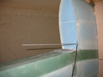
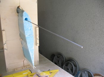
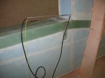
After I smoothed out the surfaces to be glassed as best possible, I wanted to get the antenna cable out of the way so I didn’t have to contend with it like I did on the Right wing. I ran a long aluminum tube thru the wing cabling channel, attached some string & the antenna cable to the tube and then pulled it all back far enough inside the channel that I could layup the BL 55.5 rib glass without messing about with the antenna cable.

Chap 19 - Left wing/glassing BL 55.5 rib

Chap 19 - Left wing/glassing BL 55.5 rib

Chap 19 - Left wing/glassing BL 55.5 rib

Chap 19 - Left wing/glassing BL 55.5 rib

I cut & laid up 2 each 3″ x 30″ UNI strips over the extrusion & along the edge of the wing bolt access hole in the infamous “V” pattern.

I put a thin layer of flox over the irregular surface just Outboard of the extrusion, between it and the foam.  I then filleted the foam/glass corners with dry micro & squeegeed micro- slurry onto foam field.

Chap 19 - Left wing/glassing BL 55.5 rib

I pre-pregged the 3-ply BID setup for the BL 55.5 inset rib & laid it up.  I overlapped it onto the extrusion area as well.

Chap 19 - Left wing/glassing BL 55.5 rib

Chap 19 - Left wing/glassing BL 55.5 rib

Chap 19 - Left wing/glassing BL 55.5 rib

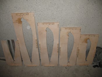
While the BL 55.5 inset rib was curing, I cut about half of the 1/4″ plywood that I had used for the fuselage bottom “sled” to use for jigs & templates for the next build, Chapter 14 – Center Section (CS) Spar, and a few other chapters as well.  I used the 3M 77 spray glue to tack the tracings onto the plywood, and then took the wood to the base wood shop to cut out the jigs & templates.

After returning home, I knife trimmed the 3-ply BID on the edges of the BL 55.5 jut out inset rib.

 Chapter 14 — Center Section Spar

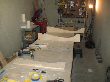
I mocked up & then cut the wood for the CS spar jig back piece and the front “shelf” pieces.  Once I got them cut to size, I mocked it up again to ensure the measurements were correct.

Chap 14 - Center Section spar jig build

Chap 14 - Center Section spar jig build

Chap 14 - CS spar jig build

Chap 14 - CS spar jig build

Chap 14 - CS spar jig build

Chap 14 - CS spar jig build

Chap 14 - Center Section spar jig build


Chap 19 – Left wing wrap up

Today I bondo’d the wing incident angle board to the top of the wing.

Chap 19 - Setting wing incident board

Since it’s only open a few days a week, I went to the wood shop on base to cut the shelves A, B & C for the Center Section (CS) Spar jig.

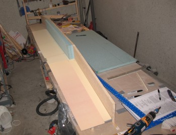
The CS spar is akin to a big beam that goes through the fuselage and sticks “straight” out each side of the fuselage at the aft end (where the rear square notches are in the fuselage).  The CS spar is what the wings bolt to (the “notch” in the wing above wraps around the end and aft side of the CS spar) via the aluminum extrusions.  It extends out away from the fuselage and ends at where you see the blue foam in the pic above, and is about as wide front-to-back, as from the front side of the shear web to front edge of the grey duct tape in the pic above.  It’s height is the same as the wing’s thickness. Essentially, it’s about a 10 ft long square box, about 6″ wide & 8″ high.

I took the angle brackets off the individual jigs & rotated the wing LE edge up on the table.  I then marked & cut the bottom glass of the BL 55.5 jut out.

Chap 19 - Left wing build

Chap 19 - Left wing build

Chap 19 - Left wing build

Chap 19 - Left wing build

I then laid the wing down flat again with the wing top up & routered out the BL 55.5 jut out are to 0.7″ deep.

Chap 19 - Glassing BL 55.5 ribI then stood the wing assembly back up & made some final preps for glassing the BL 55.5 rib tomorrow.
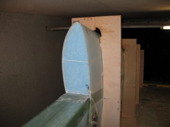
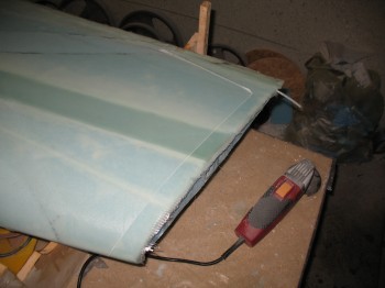
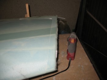
Chap 19 - Glassing BL 55.5 rib


Chapter 19 – Left wing … almost there!

Today I removed the peel ply from the Outboard extrusion/wing bolt access area.

I removed the taped foam shelf from the BL 55.5 wing front jut out.

I then cut the glass straight at the Inboard & Outboard wing ends.

Chap 19 - Left wing build

Chap 19 - Left wing build

I then grabbed the Right wing from my storage area (yeah, you know…!) & took it out to the yard to measure all the critical dimensions.  I measured the length of the LE & the spar cap to BL 55.5 jut out measurement.  I also measured the chord at the wing ends.

I cut the top side of BL 55.5 jut out edge.

Chap 19 - Left wing build

Chap 19 - Left wing build

I then cut the TE at the same distance from the LE as the Right wing.

Chap 19 - Left wing build

Chap 19 - Left wing build

Chap 19 - Left wing build

Chap 19 - Left wing build

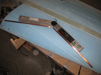
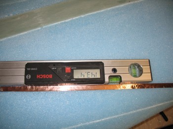
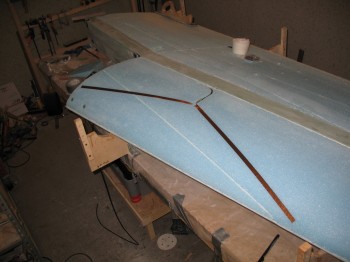
I cleaned up the shop & put the jig tops back on, and then measured the incident angles.

Chap 19 - Left wing build

Chap 19 - Left wing build

Chap 19 - Left wing build


Chapter 19 – Skinning Left Wing

I started out today by vacuuming the entire top of the wing.

Chap 19 - Left wing prep for glass

I also refilled my slow hardener bottles & restocked my blue glove supply.

I used a 50:50 slow/fast for the thick micro on the deep fill areas.  I used wet flox on the TE & 70:30 micro/flox on the LE.  I used 80:20 slow/fast microslurry for the foam fields.

My buddy Kevin helped me by working the epoxy station, and he also helped layup some of the glass as well.

After I got the foam all micro’d, I laid up the wing UNI glass that I had pre-cut.

Chap 19 - Left wing top skinned

Chap 19 - Left wing top skinned

Chap 19 - Left wing top skinned

I peel plied the Outboard extrusion area “V” that borders each side of the wing bolt access hole.  I also peel plied the front face of the extrusion (LWA3).

Chap 19 - Left wing top skinned

Chap 19 - Left wing top skinned

I laid up the 14″, 10″, 6″ plies of UNI over the Inboard extrusion/wing bolt hardpoint & overlapping up onto the wing (just like the Right wing).

Chap 19 - Left wing top skinned

I laid up the triangular ply of BID reinforcement on Outboard end of the wing & peel plied it.

Chap 19 - Left wing top skinned

I clamped & clothes-pinned an aluminum L-bracket–lined with duct tape–to the TE to keep it as straight as possible as it cures.

Chap 19 - Left wing top skinnedI trimmed the excess glass from around the edges & since the weather had turned much cooler, I turned on 2 heaters to keep the shop temp above 70° F.

I came back to check the layup about an hour later.  I had a couple of quarter sized bubbles that had developed right at the front edge of the spar cap.  I worked those out & re-checked the entire wing layup.  Everything looked good!


Chapter 19 – Final prep for top wing skin

Well, I finally finished removing the peel ply from the TE.  I then finished cleaning it up.

I sanded most of the Inboard spar cap area, including around the aluminum wing bolt extrusions.  Specifically, there’s a 1″ strip of glass between the Outboard extrusion & the side of the front of wing jut-out (BL 55.5) that was pretty rough & needed some tough love. I sanded it down & got it fairly smoothed out in that 1″ strip.  It needs to be smooth since the rib that gets glassed into the front of wing BL 55.5 jut-out will overlap onto this surface. I also cleaned up the aluminum extrusion faces & the wing bolt access overhang piece (W18).

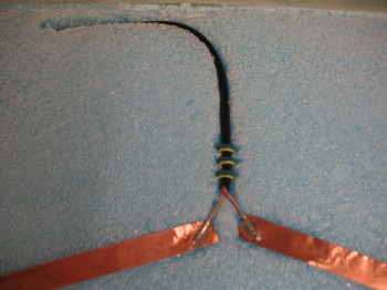
I installed the NAV2 VOR antenna by running the cable into the foam & down into the wing wiring channel.

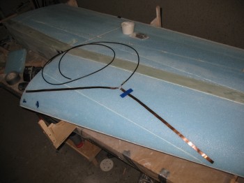
Chap 19 - Installing VOR antenna Chap 19 - Installing VOR antennaChap 19 - Installing VOR antenna Chap 19 - Installing VOR antenna Chap 19 - Installing VOR antenna Again, I formed & taped an extension for the BL 55.5 front of wing jut-out (where the blue tape strip is in the pic above) to be installed and will allow the glass to overhang straight. (both of my Inboard FC4 pieces were rounded over just a bit for about 4″, so I just want to the glass to come straight out and not follow the roundover… which is only about .1-.2″ deep)

I tacked on the 1″ x 65″ peel ply at the aileron junction (again, on the wing side).

The final large UNI layup on the wing is 1 ply of UNI that goes from the Inboard side straight out to the tip of the wing.  This starts above the aileron & follows the top edge of the aileron at the aft side of this layup.  So, I marked a spot at 5.9″ from the TE at BL 55.5 & put a spot at 4.35″ up from the TE at BL 106.25 to mark the aft UNI edge of this layup.  Now, there are a few other smaller layups that get glassed, but this is the last really big one.

Chap 19 - Prepping wing top for skinChap 19 - Prepping wing top for skin


Chap 19 – Tying up loose ends for skin!

I’m trying to get the wing prepped for the last major wing layup remaining: skinning the left wing’s upper surface.

Today I spent over 1-1/2 hours removing peel ply from the TE, and still had 18″ left to remove.

I then took the tape off the baggage pod threaded mounts.  They came out good.

Chap 19 - Baggage pod hard points

I routered the Nylaflow rudder cable conduit channel using the Dremel tool.  I then installed the Nylaflow & dry micro’d it into place.  Of course I held the conduit in place with toothpicks.

Chap 19 - Nylaflow Rudder Cable Conduit

Chap 19 - Nylaflow Rudder Cable Conduit

Chap 19 - Nylaflow Rudder Cable Conduit

Chap 19 - Nylaflow Rudder Cable Conduit

Chap 19 - Left Wing top skin prep

In the following pics you can see the damage & repair of the split at the FC2/FC3 seam (during the shear web layup & attaching the nose of the wing).

Chap 19 - Closeup of FC2/FC3 split repair

Chap 19 - FC2/FC2 split repair

I fabricated the NAV2 wing VOR antenna & mocked it up.

Chap 19 - Wing prep... VOR antenna

Chap 19 - Wing prep... VOR antenna

I wasn’t happy with the Inboard wing bolt aluminum extrusion, so I scuffed it up & re-rounded the edge, and then hit it with some primer since I had some shiny aluminum showing.  I’ll scuff up the primered surface & clean it off before glassing.