Chapter 11 – Glass Elevators

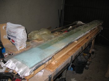
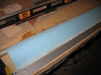
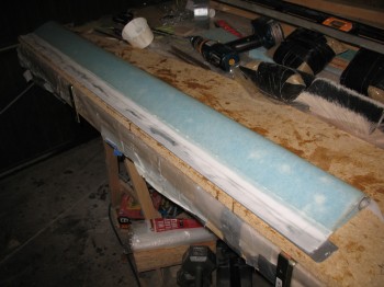
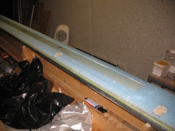
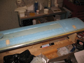
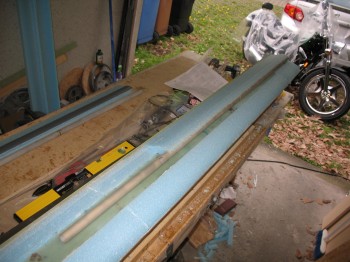
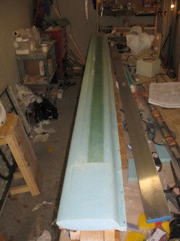
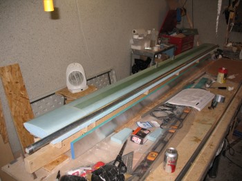
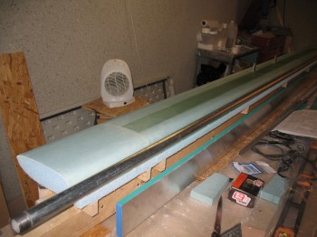
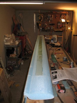
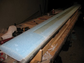
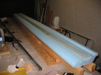
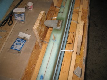
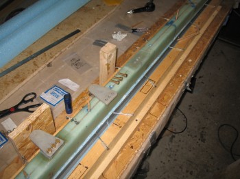
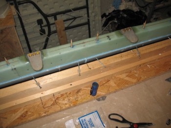
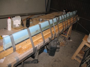
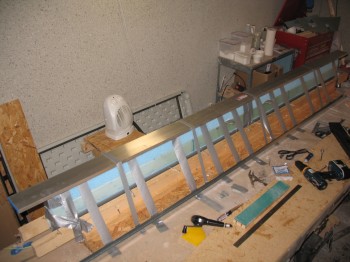
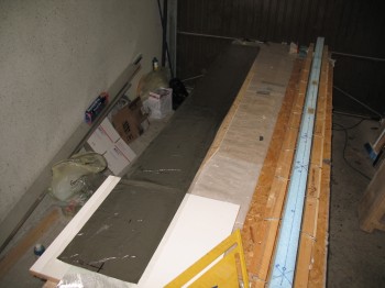
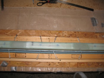
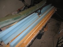
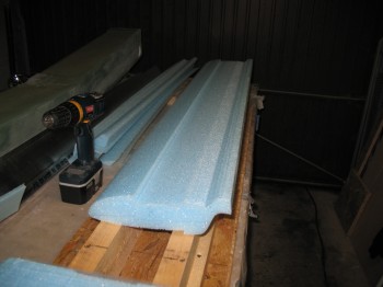
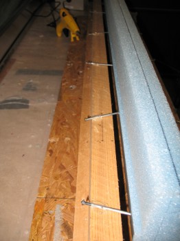
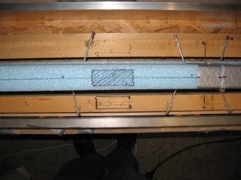
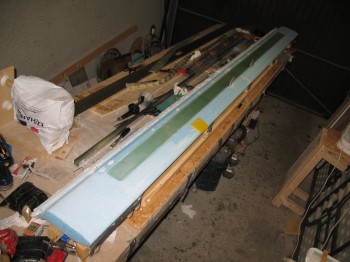
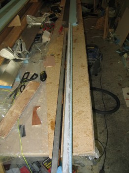
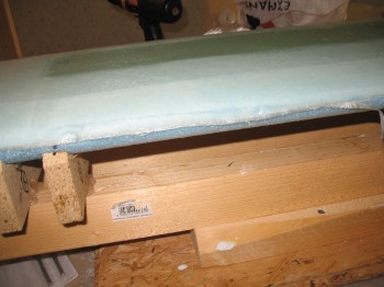
The Right elevator seemed to be curing a little bit slower than normal, so I had thrown a heater on it and that seemed to do the trick.  I pried it off the table, hit the front round edge of the glass with a hard sanding block to prep a transition for the topside glass layup that would overlap onto the bottom glass for glass-to-glass continuity.

Chap 10 - Right elevator after glass edge sanded

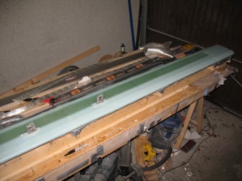
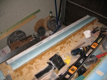
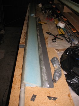
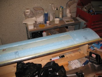
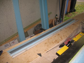
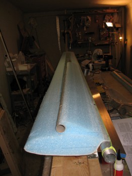
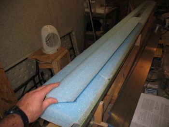
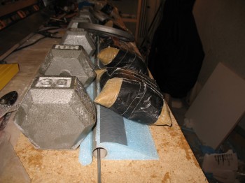
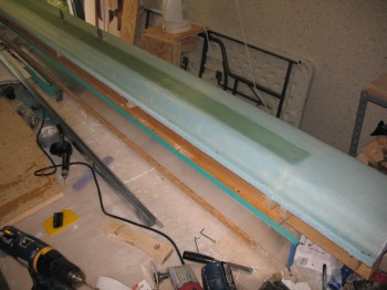
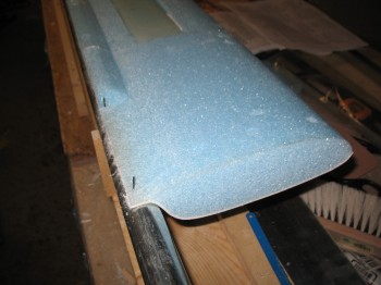
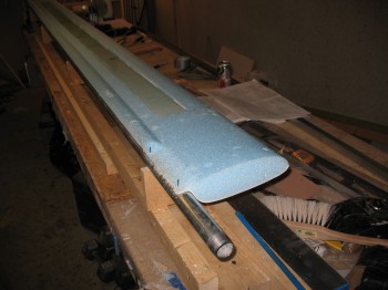
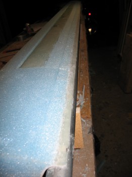
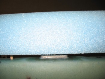
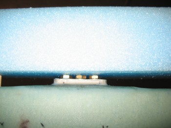
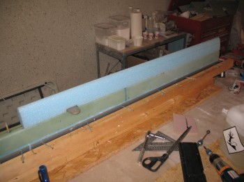
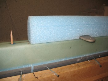
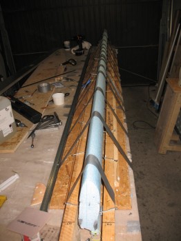
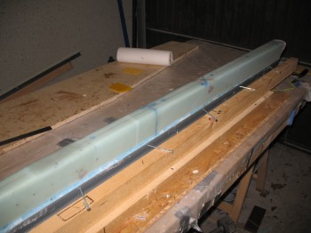
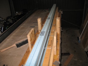
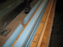
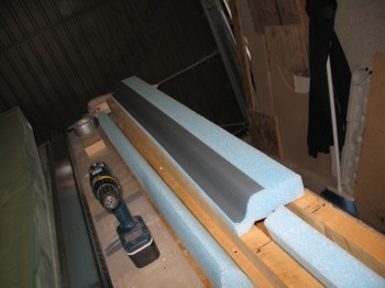
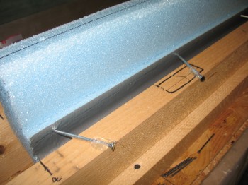
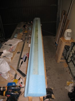
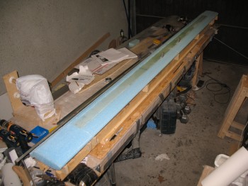
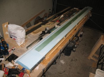
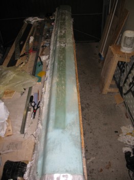
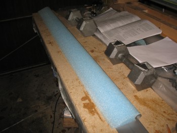
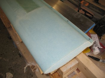
I then removed about 0.4 inches of TE foam & sanded down the newly visible glass for glass-to-glass continuity at the TE as well.  I then bondo’d the Right elevator right-side up to the workbench.

Chap 11 - Right elevator bondo'd to table

Chap 11 - Right elevator TE sanded/prepped

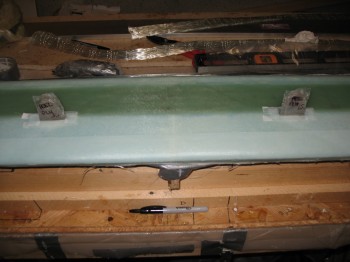
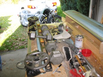
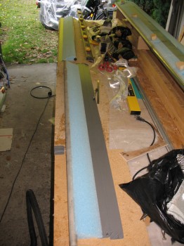
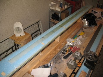
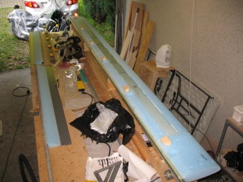
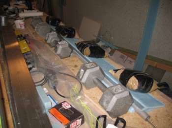
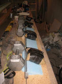
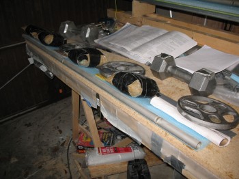
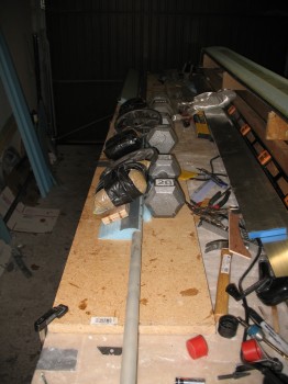
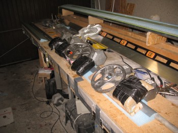
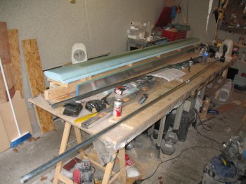
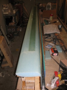
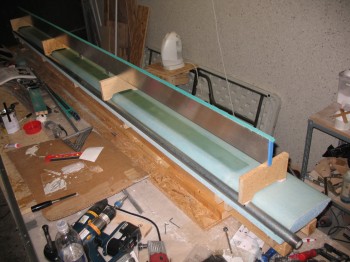
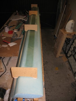
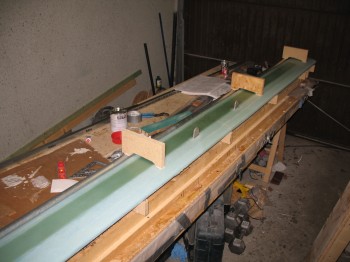
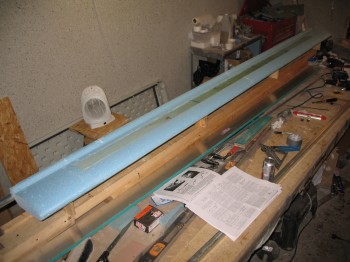
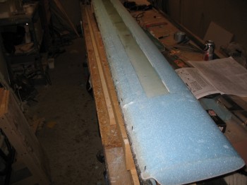
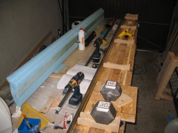
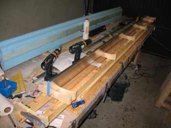
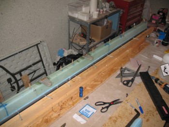
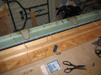
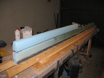
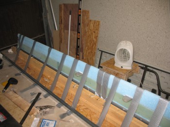
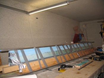
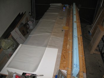
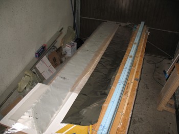
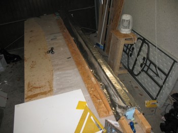
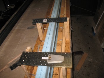
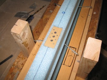
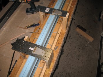
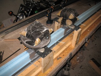
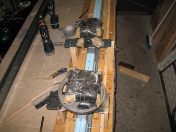
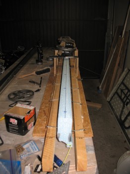
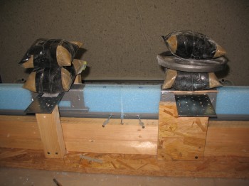
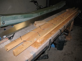
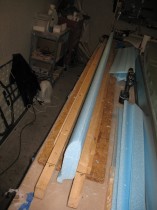
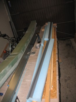
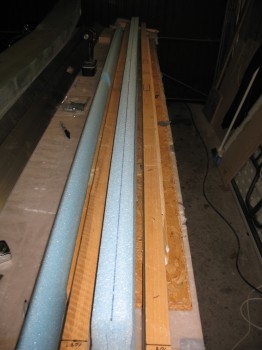
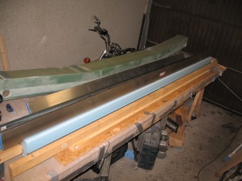
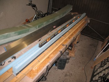
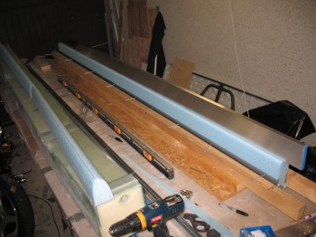
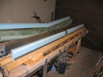
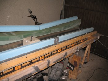
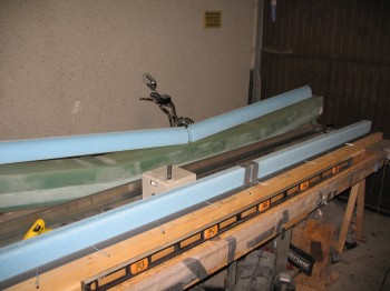
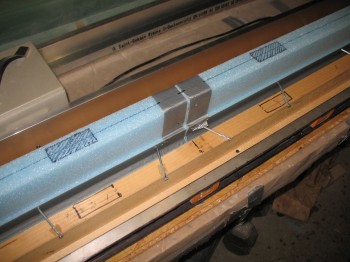
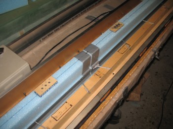
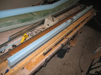
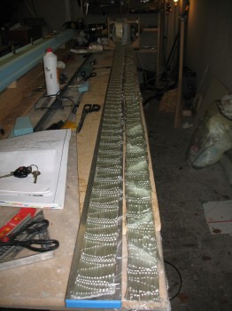
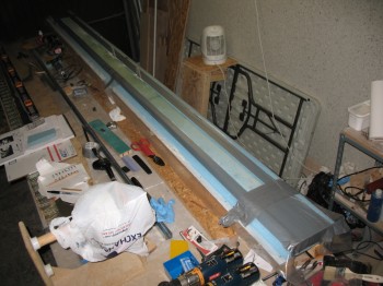
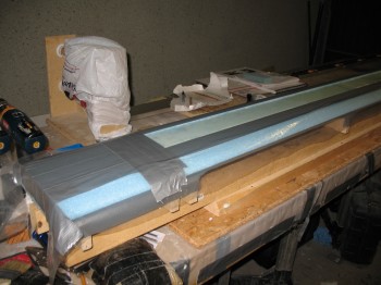
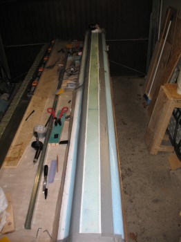
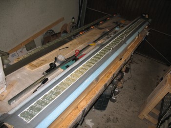
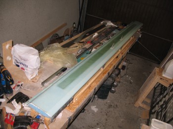
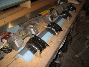
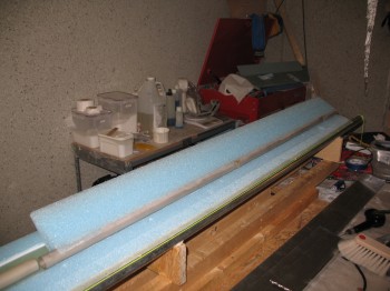
With both elevators now affixed to the workbench, I proceeded to layup the top side of the Right elevator & the bottom of the Left elevator.

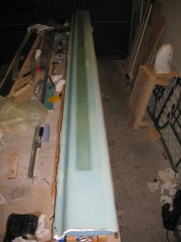
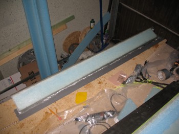
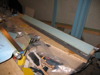
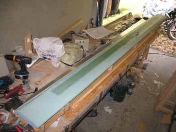
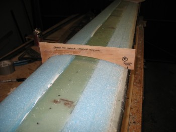
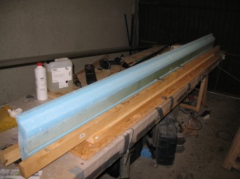
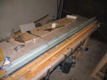
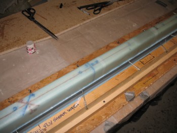
Chap 11 - Elevators R/top & L/bottom prepped Chap 11 - Right elevator top glassedChap 11 - Right elevator glassedChap 11 - Left elevator bottom glassed

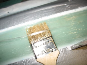
I peel plied the LE of the Right elevator, and after the epoxy had cured a bit & the glass was still tacky, I micro’d in the channel on the TE of the Right elevator & covered it with peel ply.

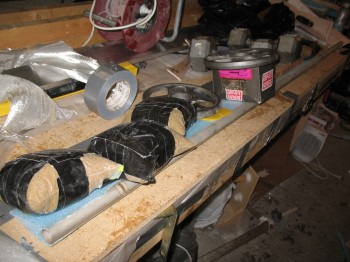
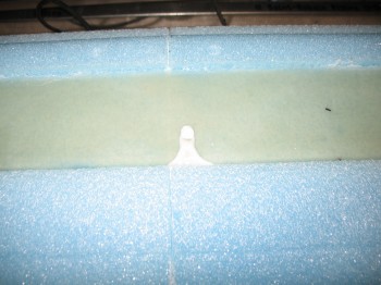
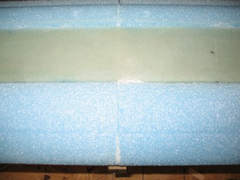
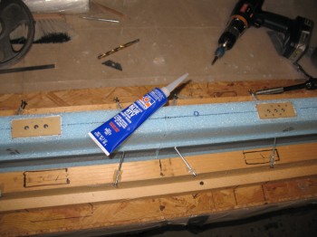
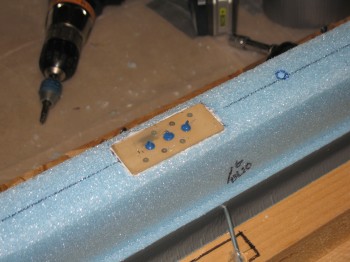
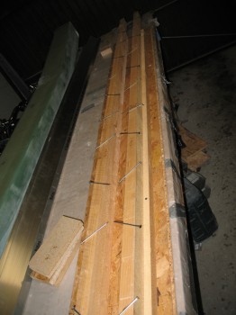
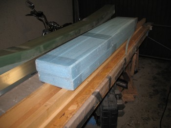
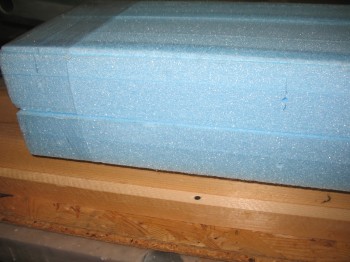
Just before I glassed the elevators, I had finished cutting all the H100 6# high density foam inserts and their respective positions in the canard (L&R of CL: 9.7″, 34.1″ & 59″).

Chap 10 - High Density Foam Inserts

Chap 10 - High Density Foam Inserts (+ Ch 11)

I micro’d in the high density foam pieces into place.

Chap 10 - Canard foam inserts micro'd in


Chapter 10 – High Density Foam Hard Points

I spent an hour or so researching and planning the torque offsets configuration & hinge placement.

Chap 10 - High Density Foam Block Inserts

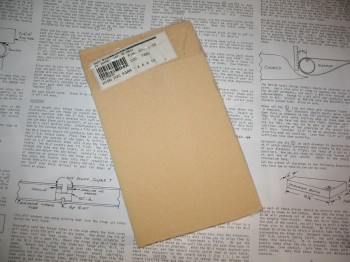
I rounded up my block of 6# high density foam.

Chap 10 - H100 6# High Density PVC Foam

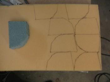
I “designed” my insert with a scrap of blue foam and once I had it locked in & test fitted into the canard, I used it as a template for the high density foam inserts.

Chap 10 - High Density Foam Block InsertsI test fitted 2 of the inserts and they fit well, but I didn’t micro them in place yet.  This foam is tough stuff!

Chap 10 - High Density Foam Block Inserts

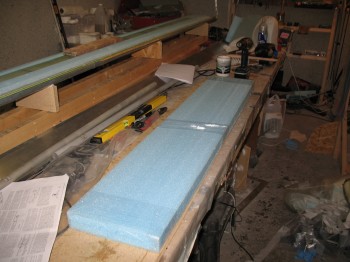
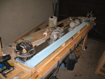
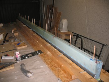
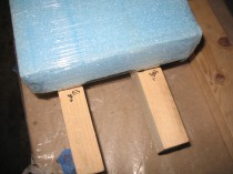
I turned my focus back onto the elevators and 5-min glued the Left elevator upside down to the workbench for glassing.

Chap 11 - Bonding elevator to workbench for glassing

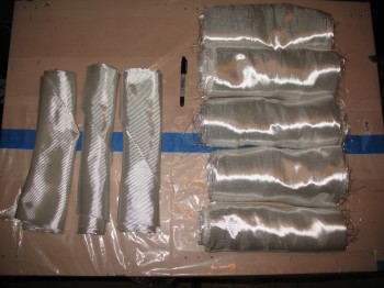
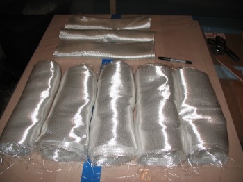
I then cut 3 sets of elevator glass: 1 set for the Left elevator bottom side, and 2 sets for the top sides of the elevators.


Chapter 11 – Elevators

Today I started building the elevators.  Not because I simply got bored with the canard, but there are foam hard mounts that get inserted into the blue canard foam near the trailing edge before it gets glassed.  These foam hard points hold the elevator hinge brackets (with a little help from a lot of flox) into the underside of the canard, allowing the elevator torque tubes to pivot around the hinge brackets . . . which are spaced at various points along the canard, matching up of course to the hinge insert slots that I riveted into the elevator torque tubes.

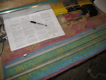
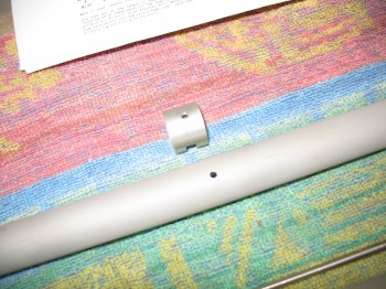
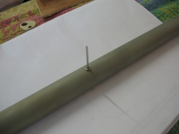
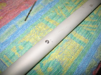
I started off the elevator build by assembling the elevator torque tubes.  I inserted the elevator torque tube hinge inserts (NC-2) into the elevator torque tubes, drilled the holes, chamfered the holes, and then riveted the hinge inserts into the torque tubes.

Chap 11 - Elevator torque tube assembly

[NOTE:  I’m using the Cozy Girrrl’s Torque Tube Offsets, which were developed for the Cozy… pretty much a wide-bodied LEZ.  These offsets allow the side hole in the fuselage walls to be made with a much tighter tolerance (read: smaller) and therefore less undesirable air (read: cold!) makes it through the elevator fuselage slots/holes.  The result of all this is that I only require 4 each hinge inserts (NC-2) vs the 5 required for a stock Long-EZ build.]

Chap 11 - Elevator torque tube assemblyChap 11 - Elevator torque tube assemblyChap 11 - Elevator torque tube assembly

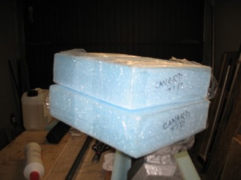
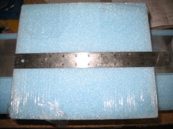
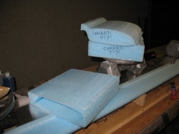
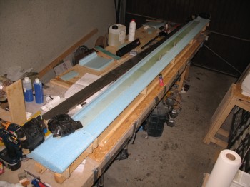
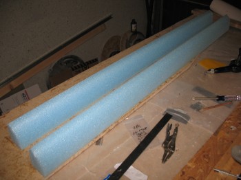
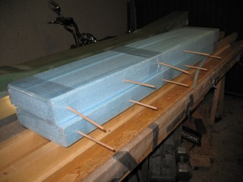
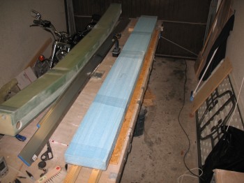
I then pulled out the foam elevator cores.  The actual elevator cores didn’t come out quite so easily, so there was a lot of razor cutting (and admittedly cussing…) and a fair amount of work to extricate the cores from the foam block.

Chap 11 - Elevator foam prep

I cleaned up the foam elevator cores & test fitted the elevator torque tubes into the round opening at the front of the foam cores.

I then installed the triangular hinge jigs (NC-7) into the hinge inserts & held them in place with the stainless steel hinge pins.  I started with the Right torque tube & inserted it into the Right elevator core with micro to secure it in place.  Since I only had 2 hinge jigs (NC-7), I let the Right elevator assembly cure before moving onto the Left torque tube (in pictures #2-4 of the Left torque tube below it appears that the foam elevator core is attached to the torque tube, but they were only mocked up before I actually micro’d them together AFTER the Right elevator torque tube and foam core were bonded together).

Chap 11 - Attaching elevator foam to torque tube

Chap 11 - Attaching elevator foam to torque tubeChap 11 - Elevator foam/torque tube attachedChap 11 - Elevator foam/torque tube attached

Chap 11 - Attaching elevator foam/torque tubeChap 11 - Attaching elevator foam/torque tubeChap 11 - Attaching elevator foam/torque tube

As the Left elevator core was curing to the torque tube, I went to my downstairs shop and cut the 2-plies of UNI at ± 30° for the Right elevator.

Chap 11 - Elevator foam/torque tube attached

I attached the Right torque tube/foam elevator assembly bottom side up to the work bench using 5-min glue, while the Left elevator torque tube/foam core assembly micro bond was curing.

Chap 11 - Elevator foam/torque tube attachedChap 11 - Elevator prep for glassChap 11 - Elevator prep for glassChap 11 - Elevator prep for glass

Chap 11 - Left elevator prepped for glass

I then microslurried the foam on the Right elevator bottom-side and glassed the 2-ply UNI layup, alternating the orientation by 30° for the 2 plies.

Chap 11 - Right elevator 1st side glassedChap 11 - Right elevator 1st side glassed


Chapter 10 – Top Spar Cap Prep

I checked the canard to ensure everything was good with the layup from yesterday.  All was good except for the LE foam damage.

Chap 10 - Canard top spar capChap 10 - Canard top spar cap I pulled the 2″ peel ply off the front LE & around the mounting tabs and took a few minutes to clean up the peel ply boogers.

Chap 10 - Canard top spar cap Chap 10 - Canard top spar cap I then “Fein” sawed/razor cut each of the canard ends so the glass was flush with the foam.  I also clamped a straightedge onto the trailing edge (TE) and cut it as well.

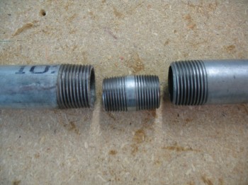
Chap 10 - Canard top spar capChap 10 - Canard top spar cap I had looked high & low for weeks to find a 130″ long pipe that would work as the TE alignment pipe.  I even borrowed a pipe from the Civil Engineers on base, but it wasn’t straight when I checked it out at the house. So I went to Praktiker & bought a 2000 mm (~78-3/4″) and 1500 mm (~59″) 1″ water pipe.  I used a 3/4″ threaded connector to help keep the 2 pipe pieces together & straight.  I cleaned the pipes with acetone & then Simple Green and then mounted them together.

Chap 10 - Making the long pipe I then bondo’d the whole assembly to the TE lip of the canard, using my aluminum straight “board” to make sure it was all straight.

Chap 10 - Canard...long pipe attachChap 10 - Canard...long pipe attachChap 10 - Canard...long pipe attachI trial fit, and then cut crescents in the wood support boards, that would hold up the canard when it was flipped over right side up.

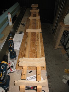
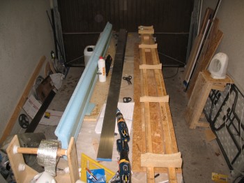
Chap 10 - Making new support baseAfter I got the 4 support boards prepped, I bondo’d them to the bottom canard surface on one side and the metal pipe on the other.

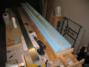
Chap 10 - Making new support base Chap 10 - Making new support base Chap 10 - Making new support base I then flipped the canard right side up & secured the end wood supports to the original wood canard jig base.

Chap 10 - Resting on new baseChap 10 - New base & canard secured I cut off the fishtail at the topside TE.

Chap 10 - Removing Canard FishtailChap 10 - Removing Canard Fishtail Chap 10 - Removing Canard Fishtail Once I got the fishtail foam removed, I then removed all the tacks and peel ply from the TE.

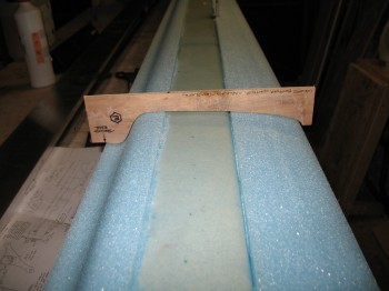
Chap 10 - TE peel ply removedChap 10 - TE peel ply removedI used the top contour checking template to finish sanding the remaining foam off the TE area left by removing the fishtail.

Chap 10 - Checking canard top contour Before the final mounting of the canard to the original base, I took it out of the garage and flipped it around end-to-end so that I could work on the LE with it at the front edge of the table, facing both the lighting and closest to the epoxy table. Then I spent about 2-1/2 hours using straight edges, string, and a laser level kit to get the canard as perfectly aligned as possible.  I had about a 0.15 inch drop at each end, so I shimmied the each end support strut with a couple of stirring sticks, which seemed to do the trick.


Chapter 10 – Bottom Spar Cap & Skin

I checked the Roncz Canard 11″ tips that were micro’d on yesterday.  Everything cured well so I pulled the nails that were holding the foam pieces together.  When I leveled out the canard, I could see where the 11″ canard tips were slightly off from the rest of the canard. So I took my time and very carefully sanded the canard tip bottom surfaces to match the rest of the canard.  I did this for both the Left & Right side.

I then precut the 7 each 3″ UNI tape lengths: 108″, 108″, 98″, 90″, 80″, 60″ and 12″.  Since the Roncz Canard plans state to simply layup the number of lengths that will appropriately fill in the spar cap trough, I can make modifications to my UNI tape lengths if and when they may be required.  I wanted to have as much of the prep work completed, since I will take Burt’s advice in the Roncz Canard plans and layup the 3″ UNI tape spar cap glass and then roll right into glassing the lower skin of the canard.
Chap 10 - Canard bottom spar cap

I carefully sanded the LE edge to knock off any excess foam from the hotknife cutting process, then vacuumed the entire canard and taped half-way up the LE.
Chap 10 - Canard bottom spar capChap 10 - Canard bottom spar cap

I tacked on a 1″ strip of peel ply down the entire TE, but with only 1/2″ on the TE and the other 1/2″ hanging overboard.  Once I finished with the peel ply, I taped around the spar cap & used plastic to protect the canard foam surface.
Chap 10 - Canard bottom spar capChap 10 - Canard bottom spar cap

I bagged (like a wedding cake frosting bag) thick micro around the edge of the spar cap.  I then laid up the spar cap using the contour template regularly to check the amount of glass in the trough.
Chap 10 - Canard bottom spar capChap 10 - Canard bottom spar capI was using a whole new batch of 3″ UNI tape that I ordered just before I left Tampa, and I have to tell you I didn’t like the new stuff at all.  There must be a new supplier to ACS because the roving threads continuously broke while trying to remove them from the glass weave, and I even found a piece of scotch tape holding the glass weave together (thankfully only once), which of course I cut out.
Chap 10 - Canard bottom spar capOnce I was finished laying up the spar cap, I took a very short break, then carefully removed the protective tape and plastic from around the edge of the spar cap trough.  I then used micro paste to fill in the joints & dings, and then microslurried the remaining canard bottom blue foam surfaces.
Chap 10 - Canard bottom skinChap 10 - Canard bottom skinI then laid up the bottom canard skin which was fairly straight forward:  1 long layer of UNI, 1 long layer of BID (4 pcs total & only overlapping in the center, not on the Outboard flight surfaces), then 1 long layer of UNI again, for 3 total layers.  The UNI is somewhat of a pain to work with at times, since it’s cut with the strands of glass, so the glass continuously wants to peel off the sides of your layup.  Dale Martin recommended that I do like many builders & cut the UNI here just a tad wider and then masking tape the edges to keep it from unraveling.  I was too lazy & cheap to do that, so I just powered through.
Chap 10 - Canard bottom skinChap 10 - Canard bottom skin

Once I glassed the lower skin layups, I knife trimmed the edges to 1/4″ and peel plied the LE with 2″ wide peel ply tape.  I also peel plied around the canard mounting tabs.
Chap 10 - Canard bottom glassingChap 10 - Canard bottom glassingChap 10 - Canard bottom glassingChap 10 - Canard bottom glassing

After a few hours had passed, I used a razor knife to cut the glass along the middle of the LE adjacent to the line of duct tape underneath.  While I was pulling away the duct tape, dead glass and peel ply, I had about a 10″ section of LE foam that simply decided it wanted out and peeled off with the tape.  I will have to fix that area before glassing the top of the canard.

With that, I double checked the layup and then let it cure.  One thing I did notice is that in a couple of areas the spar cap is a hair thicker than it should be.  So there’s about a 0.05″ ridge along the spar cap edge under the skin.  The bond looks good, there is just that small ridge that I will have to contend with when finishing the canard.



Chapter 10 – Canard Spar Cap Prep

I started today by removing the canard from the jig.  I then cleaned up the jig & extended it from 108″ to 126″.

Chap 10 - Bottom spar cap prepChap 10 - Bottom spar cap prep

I then cleaned up & sanded the 9 each K-jigs, which will spaced out as per the Roncz canard (not Chap 10) plans to support the canard as it’s upside down getting glassed–which is the next step.

As you can see, I clamped the K-jigs together and sanded them as one piece so they would be the same shape all the way down the row.  This will remove nearly all the inconsistencies in the cuts since I had to cut each one individually on the band saw.

Chap 10 - Bottom spar cap prepI then mounted the K-jigs to the canard jig base using a hot glue gun.  I used a string & my aluminum straight board to ensure they were all straight & level.

Chap 10 - Bottom spar cap prepChap 10 - Bottom spar cap prepChap 10 - Bottom spar cap prepChap 10 - Bottom spar cap prep

In the pic below there appears to be 2 extra K-jigs mounted to the end of the jig base, but those are there in preparation for the 11 inch canard tips that will get bonded to the end of the current canard structure.  Actually, the 11″ tips are more like extensions, because the actual TIPS of the canard will be shaped & glassed into place (with the ends flaring up) after the elevators are mounted.

Chap 10 - Bottom spar cap prep

I used the Canard Bottom Contour Checking Template to see how the bottom of the canard was measuring up before I mount the canard to the K-jigs.

Chap 10 - Bottom spar cap prep

I also took a minute to remove a big unsightly run of dead micro that needed to go away.

Chap 10 - Bottom spar cap prepChap 10 - Bottom spar cap prep

I then weighed down the canard after using 5-minute glue to bond the canard to the K-jigs.

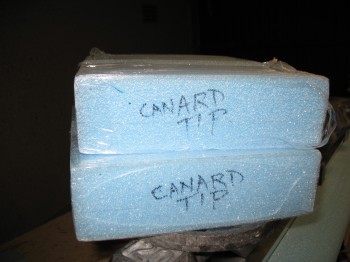
Chap 10 - Bottom spar cap prepI then grabbed the 11″ canard extensions & removed them from their foam encasements.

Chap 10 - Canard TipsChap 10 - Canard TipsChap 10 - Canard TipChap 10 - Canard Tips

It was then that I had a total brain-fart, disregarding all my jedi-training, and grabbing the bottle of “Hot Stuff” glue (Superglue) to mount the 11″ foam extensions.  Right after I mounted the canard tips on the Outboard K-jigs, I realized in short order what I had done (luckily, most of Hot Stuff glue soaked into the particle board K-jigs, so the damage was minimal).  After my duh moment was over, I whipped up some flox to keep the canard tips mounted since I had already micro’d & nailed them into place.  I also double-checked that they were straight & level on the LE, TE, top & bottom.

Chap 10 - Canard Mounted/Tips AttachedAs the canard tips and structure cured to whatever degree it had left to the K-jigs, I went down to the cutting table and spent a couple of hours cutting the glass for the canard skins.  I cut all the UNI for the top & bottom skins (5 pcs 12-1/2″ x 134″), and enough BID for the bottom skin (3 pcs 13-1/4″ @ 45°).

Chap 10 - Canard Skin GlassChap 10 - Canard Skin Glass

I pre-deployed the slow hardener, 3″ UNI tape, etc. to the garage.


Chapter 10 – A nose for canard

I started out today by drilling a 1/4″ hole at each marked spot on the top/front of the canard (in the present configuration) for the 12 each 1/4″ sharpened wood dowels that will align the front part of the canard (or “nose” or LE) to the shear web section of the canard.  This is exactly the same process as the main wings, only on a smaller scale.  Of course the wings don’t use the wood dowels to line up the front part of the wing to the shear web (unfortunately … seams to be much easier).
Chap 10 - Canard Mounting Tabs NC-CLTs

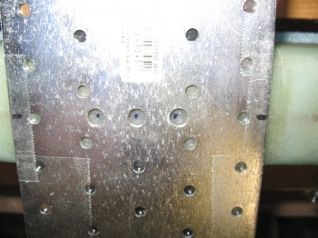
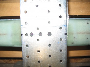
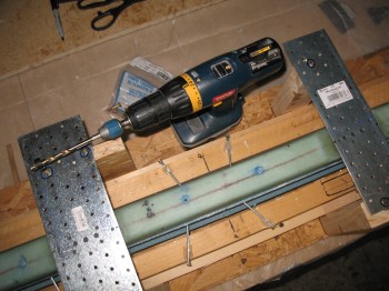
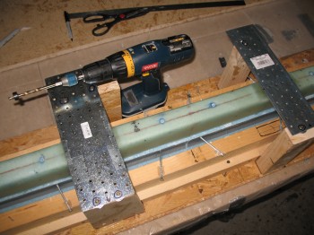
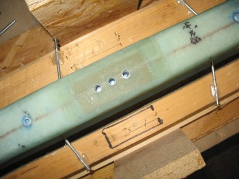
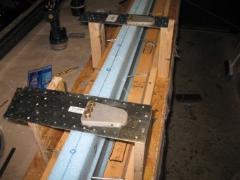
I then reinstalled the metal mounting tab jigs & their wood supports, set up a stop on my 1/4″ drill bit and drilled the 6 bolt holes for the canard mounting tabs (NC-CLT) into the ~12 plies of glass over each nutplate.

Chap 10 - Canard Mounting Tabs NC-CLTsChap 10 - Canard Mounting Tabs NC-CLTsChap 10 - Canard Mounting Tabs NC-CLTsChap 10 - Canard Mounting Tabs NC-CLTsChap 10 - Canard Mounting Tabs NC-CLTsChap 10 - Canard Mounting Tabs NC-CLTsChap 10 - Canard Mounting Tabs NC-CLTs

Then came the real job . . . cleaning the Blue RTV out of the holes in the nutplates.  It was probably something akin to a cartoon in how the Blue RTV just did not want to be extricated from those bolt holes.  Needless to say, it took A WHILE to get all that rubbery, stubborn Blue RTV out of those holes.  My best tools in doing this were my scribe and a cheap set of dental picks I picked up from Harbor Freight.

Chap 10 - Canard Mounting Tabs NC-CLTs

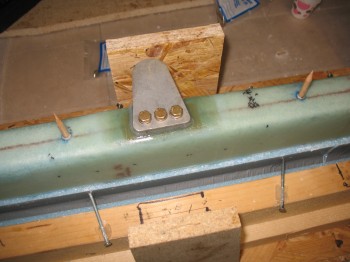
After finally getting all the Blue RTV out of the bolt holes, I mixed up some flox and attached the canard mounting tabs onto the shear web permanently.

Chap 10 - Canard Mounting Tabs NC-CLTsChap 10 - Canard Mounting Tabs NC-CLTs

As I quite often do, I mixed up a little bit too much flox, so I used it to mount the 12 sharpened 1/4″ dowels into their holes.

Chap 10 - Canard Mounting Tabs NC-CLTsChap 10 - Canard Mounting Tabs NC-CLTsChap 10 - Canard Mounting Tabs NC-CLTsChap 10 - Canard Mounting Tabs NC-CLTs

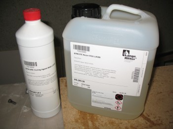
After I got both of the canard mounting tabs installed, along with all the 1/4″ alignment dowels set into place, I took a break and ran to Stuttgart to pick up some more MGS 285 epoxy and slow hardener (Stuttgart is almost 2 hours away).

MGS Epoxy Resin & Hardener Reload

Now that I was reloaded on epoxy and hardener, and my canard mounting tabs & alignment dowels were cured, I set forth to attach the front leading edge (LE) of the canard.
Chap 10 - Mounting canard "nose"Chap 10 - Mounting canard "nose"

First up on the order of battle was to notch the LE edge foam pieces at the mounting tab locations so they could fit around the mounting tab and also lie flat on the shear web surface.  As with many things in this build, it was a trial & error endeavor of taking a little foam out, then setting the foam LE back on, trimming a bit more foam, testing the fit, etc. Although the process may be a bit tedious, it really didn’t take that long… maybe 15 min for each side.

Chap 10 - Mounting canard "nose"Chap 10 - Mounting canard "nose"Chap 10 - Mounting canard "nose"Chap 10 - Mounting canard "nose"

Of course this is where the alignment dowels play a huge role.  I can see where trying to do this without the dowels–which weren’t used as per plans in the original Chapter 10–could be a lot more difficult, because it’s not about just getting the foam cut out for the mounting tab, but aligning the front canard foam piece correctly front & back (technically top-to-bottom), and the Outboard & Center alignments correct as well.  The dowels made it very EZ to just slip the second half of the canard LE foam into place and have a nice flush fit at the CL between the two canard LE foam cores.

Chap 10 - Mounting canard "nose"Chap 10 - Mounting canard "nose"

Once I got the notches set for the mounting tabs, and was sure the LE cores were aligned properly, I micro’d both foam LE cores into place.  As you can see, I used a fair amount of duct tape to ensure the LE cores had some decent pressure as they cured.

Chap 10 - Mounting canard "nose"Chap 10 - Mounting canard "nose"

Chap 10 - Mounting canard "nose"

I checked to ensure the canard LE was straight.  I was using both my 6′ long level & my new long aluminum straight “board” that I picked up from Praktiker, when I realized I could place the aluminum straight board on the top of the LE without damaging it, which added a little bit more weight and when taped at equidistant points helped to ensure the LE stayed straight.

Chap 10 - Mounting canard "nose"Chap 10 - Mounting canard "nose"


Chapter 10 – Canard Shear Web

I started out by checking the cured micro sample in the cup.  It looked good.

Then I removed the nutplate mounting assemblies.

Chap 10 - Canard BuildChap 10 - Canard Build

The nutplate installation into the foam looked good on both sides.  I cleaned up the edges a little bit from some micro squeezing out along the edges, but it only took about 5 min to have it all looking spiffy.

Chap 10 - Canard Build

I forget where, but a canard builder had offered a builder’s tip to use Blue RTV to seal the bolt holes so they’d be preserved and no epoxy would get in and muck them up.  So I sealed all 6 of the bolt holes in the nutplates with the Blue RTV.  It was a little tricky to work with, and once it got on something, it didn’t want to come off.

Chap 10 - Canard BuildChap 10 - Canard Build

I then grabbed my shear web glass that I cut last night and set it up for a pre-preg layup, just as I had done with the wing shear webs.

Chap 10 - Canard BuildChap 10 - Canard BuildI then mixed up some epoxy, wet out the shear web UNI and transferred it over to the aluminum foil.  I then transferred the pre-pregged glass to the canard.
Chap 10 - Canard BuildChap 10 - Canard Build

Once I glassed the shear web UNI layup, I dutifully added peel ply as per the stern note I left myself on the canard jig!

Chap 10 - Canard BuildChap 10 - Canard Build

You can see in the picture below that each nutplate is covered by a pad that is made up of 9-plies of 1-1/2″ x 4″ BID covered by a single ply of 4″ x 8″ BID.  This makes for stout hard points to mount the canard mounting tabs to.  The plans call for using micro around the edges of the 9-ply BID pad as somewhat as a fillet for the top 1-ply piece of BID.  I cheated a little and used flox to give a little more oomph.  (Call me chicken, but this is one area that I don’t want to be weak in any way).

Chap 10 - Canard BuildChap 10 - Canard Build


Chapter 10 – All Canard

I measured some scrap wood & cut 4 pieces for the canard mounting tabs/nutplate mounting supports and then mounted them to the canard jig base.

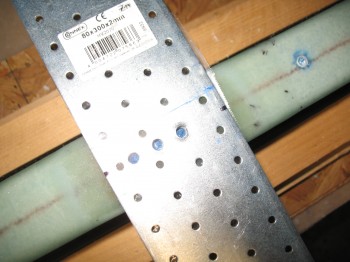
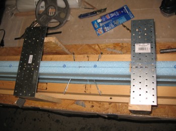
Chap 10 - NC-CLT install jigs' support posts I then took 2 pieces of scrap metal and drilled 3 holes into each using one of the NC-CLT mounting tabs as a template (so the 3 holes line up with the 3 bolt holes on the mounting tabs).

Chap 10 - Canard: Mounting tab install jig prepI then mounted the nutplate, canard mounting tab, bolts, and washers to the metal cross plate to mount to the nutplates.

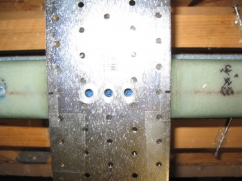
Chap 10 - Dry run of NC-CLT mounting tabs install I dug out foam in the canard face so that the mounting tab nutplate would sit flush in the hole.  Note: Standard distance from canard CL to nutplate is BL 6.5, but I went with BL 6.8 because my F22 is 0.6″ wider than stock (22.2″ vs 21.6″).

Chap 10 - Foam prep for mounting tab nut plates I did a dry run to ensure everything was lining up correctly and that my jig mounting posts were the correct height.  It all looked good.
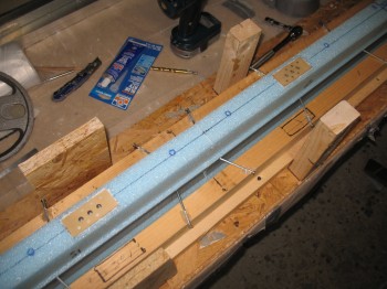
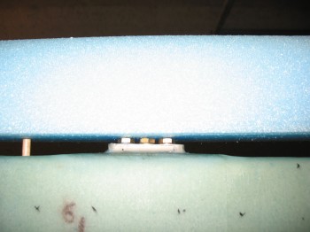
Chap 10 - Final dry run for mounting tabs installI micro’d in the nutplates (which were mounted to the steel cross templates and the mounting tabs) into the canard foam and then weighed the entire assemble down to ensure the nutplates sat flush with the foam.
Chap 10 - NC-CLT mounting tabs micro'd in placeChap 10 - NC-CLT mounting tabs micro'd in placeChap 10 - Mounting tabs micro'd/weighed in placeChap 10 - Mounting tabs micro'd/weighed in place After I had everything situated for the mounting tab nutplate install, I went to my downstairs shop and cut the UNI glass for the shear web.  I then pre-deployed the shear web to the garage.

After dinner I checked the micro left over in the cup.  It was still just a tad spongy, and the temp had dropped a bit, so I cranked up a couple heaters to warm things up a tad.
 

Chapter 10 – Roncz Canard Build

I picked up some 4″ nails and another, longer straight aluminum straight edge “board” from Praktiker today.  Now I’m ready to start my Roncz Canard build in earnest.
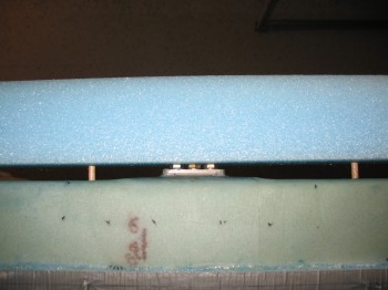
Chap 10 - Roncz Canard BuildChap 10 - Roncz Canard Build

After finalizing the Roncz Canard Jig prep, I pulled the foam canard cores out and started aligning them on the jig.

BTW, the Roncz Canard build uses a completely different set of plans than the original plans.  Now, that being said, the Roncz Canard Plans quite often refer back to the original plans Chapter 10 to accomplish many of the build steps.

Chap 10 - Roncz Canard BuildChap 10 - Roncz Canard Build

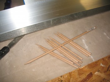
I broke out my sharpened wooden 1/4″ dowels I made last September.

Chap 10 - Roncz Canard Build

Chap 10 - Roncz Canard Build

You may have noticed that I had pre-marked the centerline and then went 54″ out in each direction.  Obviously, added together the entire length of the middle core of the canard is 108″ total (these pics are of just the middle core so far).

Chap 10 - Roncz Canard Build

Chap 10 - Roncz Canard Build

After removing the front rounded nose of the canard from each side I taped up around the bottom lip of the canard (on the aft section of the foam core) for what will be yet another shear web layup (my last on this bird!).

Chap 10 - Roncz Canard Build

Chap 10 - Roncz Canard Build

I marked a line down the CL on the top of the shear web.  Technically this line is supposed to be at WL 19.4, but I have no idea where that is.  And reading what other builders have posted on the forums, neither do they!

Chap 10 - Roncz Canard BuildChap 10 - Roncz Canard Build

I leveled out the foam canard core to ensure it was straight along the entire top edge and then held it in place with the 4″ nails stuck into the side of the core and into the protective tape . . . just below the edge of the tape (and the edge of the shear web).

Chap 10 - Roncz Canard Build

Chap 10 - Roncz Canard Build

I hot glued all the nails to the jig for just one half of the canard foam core.

Chap 10 - Roncz Canard BuildChap 10 - Roncz Canard Build

I then whipped up some micro and bonded the 2 foam core sides together.  As you can see, this is much more easily accomplished when one of the core halves is held securely in place and immobilized.  Once I set the two halves in place (taping along each connecting edge to protect the foam) I then hot glued all the nails in place to the wood jig for the other foam core half.

Chap 10 - Roncz Canard BuildChap 10 - Roncz Canard BuildChap 10 - Roncz Canard BuildI then marked up the locations of the NCT tab mounts to show where they will be situated (these are the tabs that will hold the canard to the fuselage, at/on bulkhead F22).

Chap 10 - Roncz Canard BuildChap 10 - Roncz Canard BuildChap 10 - Roncz Canard BuildChap 10 - Roncz Canard BuildBefore closing up for the evening I turned the HEATER ON!  (This definitely ain’t Tampa!)