Chapter 13/23/25 – Bottom cowl trimmed

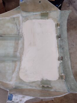
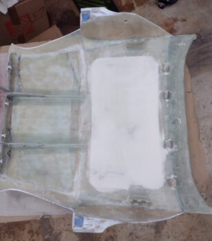
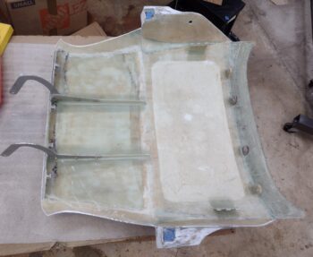
I started out today by giving the inside of the aft nose/avionics cover “window” looking area a quick sanding to rough it up in prep for micro finish.

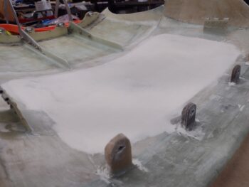
I then applied a decent layer of micro/West 410 on the “window” looking area of the inside surface of the aft nose/avionics cover.  I used fast hardener so that it would be cured by this evening, and then set it off to the side.

I then called the folks at Jet-Hot to discuss ceramic coatings for the exhaust pipes.  I had a very informative discussion with their sales rep Debbie for a good half hour while she went through the different types of coatings they offer.  I got off the call with a little bit of homework (research) to do, while they actually had some to do on their end as well.  Clinton from Custom Aircraft Parts (who I also emailed about the exhaust pipes) recommended these folks, and I have to say my initial impression of them is excellent.

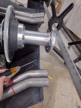
After reviewing my notes on Mike Melvill’s engine, cowling, prop and exhaust pipe configurations, I then got back into the shop to figure out where the aft edge of the top and bottom cowlings needed to be.  After a number of machinations, checks and rechecks, a bit more research here and there, I finally got my numbers dialed in and a straight line drawn across the aft edge of the bottom cowling (note I’m using the screw- driver to point out the line).

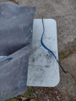
Here’s a genera idea of what is coming off the aft edge of the cowling… I marked this line a few days ago on a swag of what this would look like.

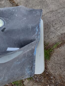
I then removed the lower cowling, took it outside and prepped to trim it with my trusty Fein saw… which you can see I did in pic #2.  I then sanded the aft edge to ensure it was straight.

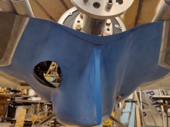
Back in the shop I remounted the lower cowling and then double-checked the aft edge with a yardstick to ensure it was straight… it is.  Looking pretty good!

Here’s a shot of the freshly trimmed aft edge of the lower cowling.

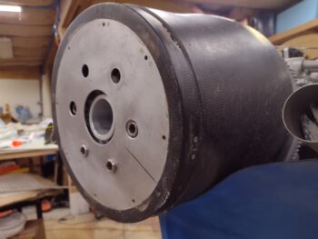
Alas… sadly the “lamp shade” flow guide on my Catto prop spinner assembly still doesn’t fit with the cowl set as it is.  This means I’m either going to have to modify the flow guide or simple sell the spinner assembly outright.  I’m leaning towards the former since I like the spinner and they’re hard to come by these days… and I seriously don’t want to take the time to make one myself.

I then went to dinner with Jess and after returning back home, I grabbed the aft nose/ avionics cover to sand down the now cured micro/West 410 finish.  Although it took a bit of elbow grease (doesn’t it always), it sanded out nicely.

Although I got most of it done, this was just the initial sanding to knock down all the high spots before it cured rock solid.  Tomorrow I’ll fine tune it and either do a few West 410 touchups, or just jump right into a couple rounds of epoxy wipes.

And with that, I called it a night!


Chapter 23 – Engine mount bolts

I spent the first part of today catching up on my blog posts.  I basically cut and pasted the early ones off my MacBook which is having issues and am now working off a Windows laptop.

I then spent a good hour torqueing the lower engine bolts to specs.  If you look closely you’ll see the AN970 wide area washer shim that I added on the bottom mounts to get the engine angle closer to where it should be 1-2°.   I’ll remind you that this was done in consultation with the folks at Lord engine mounts, not just willy-nilly.

I have castellated nuts with cotter pins on the 2 top engine mounts, and I did the same for the lower left engine mount… but what a ginormous PITA!

Here’s a wider shot of the torqued-to-spec-after-adding-shim lower left engine mount.

As far as a castellated nut with cotter pin on the lower right engine mount? … uh, no way!  I called no joy on this bubba right out of the gate since there is about zero clearance to get any of MY tools in there to get a cotter pin installed.  I simply went with the original AN363-720 nut called out in the Long-EZ IIL plans.

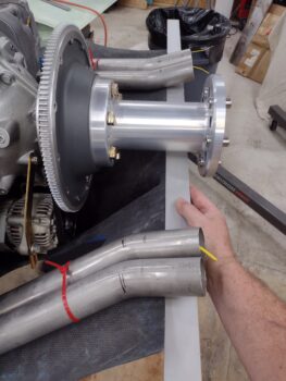
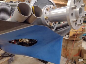
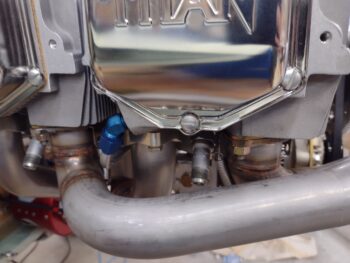
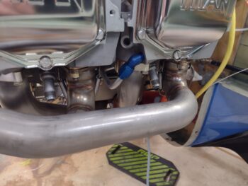
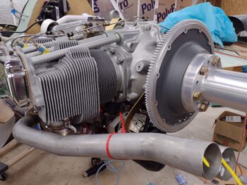
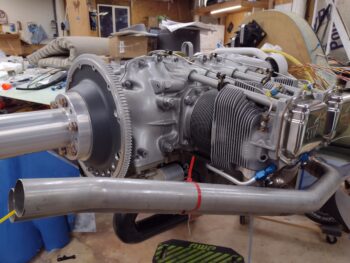
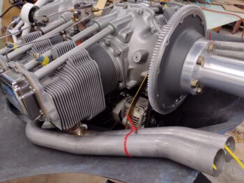
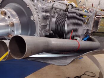
I then had a good conversation with Clinton at Custom Aircraft Parts.  He asked me to send him some pics of the left exhaust pipes to coordinate possibly sending them back to him to have the outboard rebent and the inboard pipe cut and rewelded to get them angled up at the aft end and off the bottom cowling.

Here are a few of the pics that I sent to Clinton.

With the exhaust pipes being so close to the cowling (Dave Anderson’s are as well with his Melvill cowlings so he applied heat shields to the inside surfaces of his cowling) Clinton highly recommended getting them ceramic coated to reduce the emissive heat impact on the cowling surfaces.  At this point I’m very much leaning towards BOTH ceramic coating and heat shields… and of course will be doing much more research and fact finding on those.

Chapter 8/14/23 – Forward engine bolts

Over the last week, save going out on the boat and fireworks watching for July 4th, I’ve been scurrying about cleaning up the shop and getting my build priorities in order.  That being said, this blog post covers the last few days of my build shenanigans.

One task, that in part led me down the 3D printing rabbit hole for a good month plus (combined with throwing my back out!) was the issue with the too-short oil dipstick/filler tube.  Well, after some height confirmation and testing with the upper cowling on —and a bunch of research— I’m happy to report that I pulled the trigger on a new oil dipstick & filler tube from Aircraft Specialties Services.

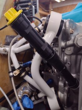
You may note from the pics below that this doesn’t look like Grandpa’s ol’ plastic Lycoming oil tube, and that’s because it is most definitely not.  The 10.57″ Lycoming oil level tube is p/n 75767, whereas this (again, after a good bit of research) is the Superior Air Parts anodized aluminum oil tube, p/n SL75767.   Note the lack of protrusions in the middle area that lends this tube the ability to stay as far off as possible from the engine mount tube.  Hopefully, this tube will put this issue to bed!

With the oil dipstick/filler/level tube ordered and on its way, I then started back on the engine to get its position situated and finalized.  Yes, in my fast and loose style of living dangerously, I didn’t have the very forward bolts of my engine mount extrusions installed yet (shown below) to accommodate working all the engine electrical components in the GIB headrest.

Thus, to ensure full clamping pressure of the forward engine extrusion bolts, I lifted the engine up slightly to relieve any downward pressure on the engine extrusions (aft) that might lift the engine extrusions upward on forward side.

A quick aside before I continue on with the forward engine extrusion bolts.
** Note the two left exhaust pipes showing in the above pic.  Although I trimmed them to minimize their overall height, they still need to be tilted up at the aft end to eliminate their closeness to the inside surface of the bottom cowling.  Once I get the engine bottom mounts finalized (they’re currently tight but not torqued fully to spec), I’ll assess and query Clinton at Custom Aircraft Parts about bending the outboard/forward exhaust pipe and cutting rewelding the inboard/aft exhaust pipe.  This should eliminate/greatly minimize any cowling rework. Note that the left side exhaust pipes are close, but acceptable enough that they don’t need any rework (bottom line: this is a tight cowling!) **

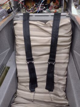
Now, back to the forward engine extrusion bolts.  First, in the pic below note immediately above the seatbelt strap on the right side of the pic is a red electrical FastOn terminal. Immediately behind that is the 90° aluminum extrusion that traverses the bottom of the GIB headrest engine electronics bay from one side to the other, and secures the bottom sides of the respective components… I installed this first since after the seatbelt bar was installed it would have been much more difficult to install this extrusion.

As you can see, the forward engine extrusion bolts secure the outboard ends of the strap bar for the GIB upper seatbelts.  Why this bar versus the plans method of attaching the upper seatbelt straps for the GIB?  Have you ever ridden a hairy roller coaster at an amusement park?  They pull the padded bar down over your shoulders so that your head barely fits through it, not out on edges of your shoulders.  Because not only does is not hold as well on the edges of your shoulders, it’s uncomfortable!

If you look a bit closer you can see two screws, each about an inch inboard of each strap.  These inboard stops essentially provides a “slot” on each side to move the straps back and forth, with the furthest outboard position still about inch inboard from the plans position.  These screw points also secure the bar from flexing or bending in the middle for better rigidity.

I’ll note for clarity’s sake that although I’ve been using the term “bar” here, that it is actually a 6061 square tube.  Moreover, there is an alodined 2024 insert with a 0.25″ thru-hole mounted inside each end of the tube to ensure the AN4 bolt clamping pressure doesn’t collapse the square tube.

After installing the forward engine extrusion bolts and GIB upper seatbelt strap bar, I then lowered the engine hoist to let the engine settle back into its normal resting state. I then rolled the engine hoist out of the way and removed the bottom cowling.

Looking over everything on the bottom of the engine, I realized that I hadn’t yet gotten around to tapping the bolt threads for 2 of the bolts that need to go into the carbon fiber air induction tube flange to secure it to the fuel injection servo’s inlet face.  The issue is that the unthreaded shank of each bolt doesn’t allow it to be threaded in all the way.  With these bolt threads tapped, all the hardware is ready to go to secure the air induction tube to the fuel injection servo.

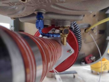
Finally, I took another hard look at the sniffle valve.  I discuss this in one of my latest videos where after I tweaked the SCEET tubing to remove any internal bumps and wrinkles, the end result is that it also removed the slight downward curve (dip) of the SCEET tubing.  With the SCEET tubing now a straighter line from point a (RAM air can) to point b (air induction tube) the 90° sniffle valve fitting is a bit too close for comfort to the SCEET tubing [this older pic shows the sniffle valve I’m talking about with the SCEET in the previous “dipped” configuration].

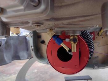
To remedy this, I’m going back to my original sniffle valve configuration where I first have a 45° street elbow installed in the bottom of the cold air plenum followed by the actual sniffle valve (see pic below).  This 45° angle should provide immediate clearance between the sniffle valve and the SCEET tubing below it.

Since I stole the only 45° street elbow I had on hand for the MAP block install, I fired off an order for another couple elbows.

Pressing forward!

Chapter 18/25 – Canopy tape removed

Yes, getting back on the plane build has been a lot longer in coming than I had planned.  Between getting some much needed house repairs knocked out, prepping the boat/initial boating season shake down cruise (a must here!), some family drama (not mine!) and a final summer mini-vacay down to Florida before hopping back into things, it’s been a busy spring/summer thus far . . .  to say the least!

My first task back in the shop was to get something knocked out that’s been nagging me in the back of my brain for a good bit . . .

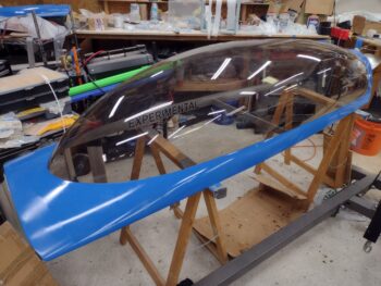
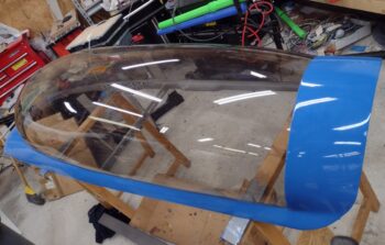
I wanted to get the painting edge tape removed from the canopy to ensure it didn’t get too emotionally —moreover physically!— attached to the canopy.  Also I wanted to ensure no major paint blobs had decided to take up residency on the edge of the canopy.

Thankfully with a little coaxing the tape came right off.

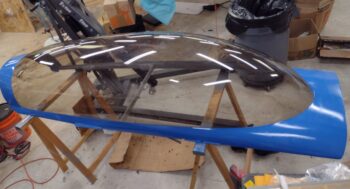
I then spent about 20 minutes cleaning up the small bits of tape left on the edge and any minor paint seepages that wicked up onto the canopy (maybe 3/16″ high at the most) with the very careful use of a razor blade.

I’m very happy that I had no unpleasant surprises regarding the canopy.  I’ll point out that this paint job on the canopy is not the final one… actually most of it will be sanded off and I’ll be shooting paint for the final topside paint (including all the white paint on the bird).

Next I’ll focus on some more maintenance items such as battery and IBBS charging, as well as swapping out the desiccant plugs in the engine.

Chapter 3 – Tooling up: Mistress Build

Happy Cinco De Mayo everyone!

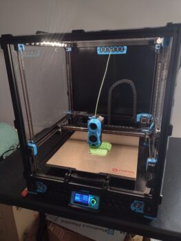
Just wanted to do a quick post showing the new Voron 2.4 3D printer is operationally complete and kicking out parts.  Moreover, my back is back and I am operational as well!

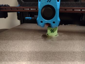
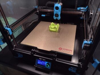
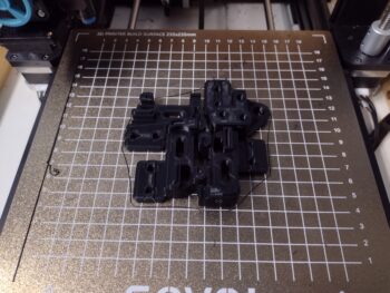
Here is the first print (in PLA) on the Voron 2.4:

I then did a few other torture test prints before kicking this one off.  Normally this would have been nearly a 2-day print on Bob or Sally, but on the Voron it took about 11 hours.

A few days later I had the new Voron 2.4 dialed in even more and started printing no kidding ABS parts… as advertised, this thing is a BEAST!

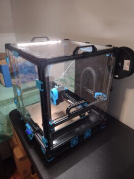
Just one final shot of my newly built and operational Voron 2.4 3D printer.  I’ll stop boring you guys with non-airplane building stuff (although very related & critical for my plane build).  Also wanted to let you all know what I was up to while down for the count with my back being thrown out!

That being said, with Mother’s Day and Jess’s birthday coming up over the next couple of weeks, I’ll again be offline from the plane build (I have some house repairs that really need to get done as well) for a good 2-3 weeks.

But I’ll be back to it ASAP!

Chapter 3 – Getting old & tooling up!

Around the time of my last post, my old age (and previous injury) showed up as I threw my back out, majorly.  I figured it would last just a few days but it was fairly severe for well over a week, and I’m just now getting comfortable doing some stuff without crazy pain.

As I was researching a new 3D printer to replace Bob, I found a couple of things that intrigued me greatly.  First, was the new plethora of high-end carbon fiber filaments that can be 3D printed (on a higher end 3D printer) to create some phenomenally strong parts.

Next, was a 3D printer that could print those carbon fiber filaments in not only an enclosed unit, but way faster than what I’ve ever been able to print and with a build volume that is quite impressive.  The only catch is that you have to either spend well over $10K for one of these 3D printers …. or, you can use one of the many published open source design machines that are out there.  Uh, just one catch on the latter: you may be able to find one second-hand, otherwise these have to be built versus just shelling out a large chunk of cash.

One such 3D printer that I seriously had my eye on was the Voron 2.4.  Although you can self source the materials to build one, there are a few different companies that sell kits with just about everything you need… except one major thing is not included: 3D printed parts.

If you’re interested, here’s a pretty good overview of the Voron 2.4:

You see, the major components (brackets, connectors, housings, etc.) of these 3D printers are ABS plastic, that you can either buy outright or print yourself.  This is one reason I went with the Sovol SV-06 3D printer, because at some point IN THE FUTURE I planned on definitely building one of these beasts.  And since I’m a) cheap, and b) wanted the experience, I would do my own 3D printing of the ABS parts.

The future is now!

Then I threw my back out.  In between stretching and back exercises, I spent a good bit of time on the computer researching both Long-EZ build stuff and 3D printing stuff.  I think boredom got the best of me and during my research I ran across an open box Voron 2.4 kit on Ebay selling for hundreds less than currently available elsewhere… yep, I pulled the trigger.

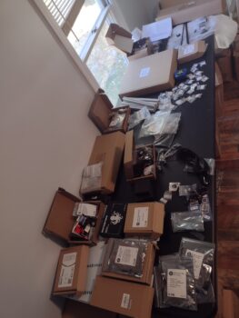
Here’s the unboxing and inventorying of the kit.

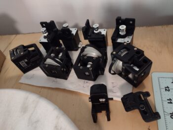
Once I pulled the trigger on the kit, I started 3D printing the ABS parts in earnest.  I had “Sally” (the new printer) working just about 24/7 printing out the parts.  I had a box of unopened black ABS on hand for over 6 months that I was going to test out with Bob, but never got to it.  So I used it as my main color for the Voron 2.4.

My plan was to work on the Voron 2.4 3D printer until my back was better, just another few days I guessed.  But this was one bugger of an injury, and I was still pretty tender for another week plus.

Since Sally was doing the major work at this point, it allowed me to recover in a decently leisurely fashion while still getting something accomplished.  It really didn’t take long to assembly the parts once I had the 3D printed parts created.  I would construct the parts for a bit, then take a break, do my back stretches, do more prints, more back exercises, more assembly, etc.

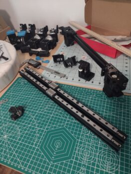
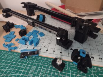
Here’s some more parts of the Voron 2.4 being assembled.  I decided to use blue as my accent color and ordered a roll of ABS from Amazon, which I had in hand a few days later.

The Voron 2.4 uses linear rails for all the axes so it is very stable, which is obviously a requirement to allow printing at high speeds.

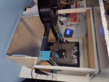
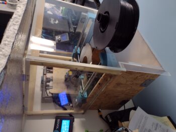
Just some examples of a few more black and blue 3D printed ABS parts.  I have to say, although somewhat slow, Sally did a great job of printing out these parts and the enclosure on the Sovol worked a treat.

I do plan on getting back on the plane build as soon as possible, and have been doing some good research on that as well (I’ll report on all that as I come to those components during the build).  In the meantime, I’ll continue to putter around like an old man and at least get this Voron 3D printer as far along as possible until I jump back on the plane.

Chapter 3 – Bob is dead :(

Or shall we say Bob (my 3D printer) is currently in a coma and non-responsive.  Alas, it was a good run Bob!

Here’s the story.  After I printed out the oil dipstick/filler tube extension, I not surprisingly had a number of other parts in the queue to 3D print.  I got a number of those items printed over the next couple of days and was doing a fair bit of CAD work as well.

Then out of nowhere Bob up and died.

I spent a good couple of days troubleshooting Bob’s ailment, but much like today’s doctors I couldn’t figure it out, so I left him to die… alone… in the corner. (ha)  [I’ll fix him later when I have time to troubleshoot EVERYTHING].

If you’ve read more than just a couple of my blog posts or have watched any of my videos, you know that 3D printing has become indispensable to me for modeling up or making Long-EZ parts.  Especially checking out fit, function and design before machining parts.

I spent a couple of days researching a replacement 3D printer that wasn’t going to break the bank, and also wanted to ensure the printer was configured such that would allow me to somewhat easily relocate the major components (power supply, electronics, and control screen) off the frame to enclose it for 3D printing ABS.

The answer was this machine: the Sovol SV-06.

With a pretty good idea of what my plan would be to enclose this 3D printer, I started collecting/buying materials and slapping stuff together immediately after I pulled the trigger to buy it.

A few days later I received the new 3D printer and had it unboxed and together in 20 minutes.  Within the next couple of days I had it dialed in and printing well.  And also enclosed in my hack, makeshift enclosure (I have front doors for the enclosure but got so busy printing that I resorted to merely shoving an insulated foam board against the front to keep the heat in . . .  combat 3D printing!)

So I’m back up and running with a working 3D printer, and am loving my new capability of printing ABS!

Moving on!

Chapter 23 – Oil dipstick tube

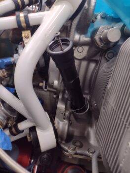
Over the last few days I’ve been involved in trying to figure out a solution for my oil dipstick/filler tube.  As you can see, the wide area at the top of the oil filler tube is uncomfortably close to the engine motor mount tube.  In fact, it’s so close that since the engine has been installed to the motor mount, I have NEVER had the dipstick in place… it just won’t thread in with the wider dipstick handle preventing it from being installed.

I know in the past builders have manipulated the length of this oil tube (usually shorter) with cutting it and then wrapping it with fiberglass.  Due to the position of the top cowling oil dipstick access door —to check the oil level pre-flight— I certainly don’t want this oil tube shorter… I want it readily available just inside the cowling access door to avoid any mandatory crazy gymnastics (on my part) to simply check the oil (e.g. such as having to climb into the back seat, etc.).

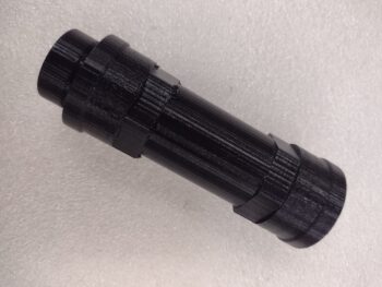
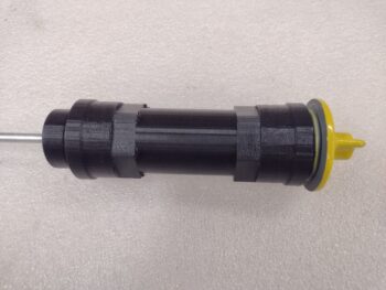
In lieu of my previous post on this subject, I modeled up an extension in Fusion 360 CAD and after too many attempts was finally able to get my 3D printer (AKA “Bob”) to print it out.  Note in the pic below the lower right was the bottom of the print, the upper left was the top and final portion to be printed out.  I point this out since in Fusion 360 when creating threads, there’s a little tick box that is used when you want to physically model threads vs simply have them show up on screen.  I (apparently!) forget to tick that block and was unpleasantly surprised to find that my part printed out sans threads (male) on one side.

The inside threads, for the dipstick, did print out.  Although the tolerance is a bit too tight and I had to really use some force to get the dipstick threaded in to the point it is in the pic.

This 3D printed extension is still just part of the info and data collection phase, R&D if you will, and I’m still looking at all available options.  That being said, the primary downside of this adding-an-extension method to fix this issue is that the widest part of the oil tube is still very close to engine mount tube.  Should I leave the small gap or simply pad it and secure the oil tube to the engine mount tube somehow that avoids vibratory chaffing but still allows movement betwixt motor and mount?  Moreover, if I did make the extension would it be some type of heat resistant plastic or machined out of aluminum?

Clearly one of the best options would to simply get a taller oil dipstick/filler tube where the actual tube part is narrowest as it crosses the area of the engine mount tube.  I’ve done a very initial look at those, but am hesitant to plop down nearly $200 for a new tube just yet!  Clearly I’ll flush out all available options first.

Finally, I will note that I did buy a length of solid 3/16″ 6061 aluminum rod that I will replace the current dipstick rod with once & however the oil dipstick tube has been increased in height.

Chapter 23 – Exhaust pipes trimmed

Today was all about completing the long-overdue exhaust pipe surgery to better allow the exhaust pipes to fit inside the lower cowling.

I spent a good couple of hours going over my notes and finalizing the no-kidding plan on how to proceed with getting the engine set and the bottom cowling fitted into place.  Step 1 was to trim the exhaust pipes at the top flange on both male and female sides of the slip joint to then assess if the trimming resolved the clearance issue between exhaust pipes and lower cowling.

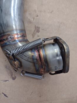
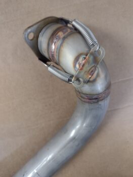
I grabbed these shots of cylinder #1 and #3 exhaust pipes to ensure I captured exactly how the springs needed to go back on.  Speaking of the springs, I had whole-heartedly expected to have needed to replace the springs, but due to the comparatively scant amount of trim material (more on that below) and the twist of the pipes stretching the springs when mounted on the cylinder, I don’t see that new springs will be required.

After speaking with Clinton from Custom Aircraft Parts in early February about my exhaust pipe vs cowling clearance issues, he told me that they couldn’t custom re-weld my exhaust pipes without my bird physically there… and I get that.  If one or two welds or angles needed to be tweaked, as would have invariably been the case, then sending the pipes back and forth for the mods would have been a few hundred dollars just in shipping alone.

Clinton told me about the option of trimming the inner and outer slip joint tubes to lessen the overall height of the pipes, but cautioned that I should leave at least 3/4″ of mating tube between the flange side and the pipe side to ensure no exhaust leaks.

While I was talking to Clinton on the phone, and what I reported in my 3 Feb blog post was that I had 1.2″ of slip joint tube between the underside of the flange to the end of the weld where the outer slip joint tube was clearly visible.  Thus I planned on removing a 1/2″ and leaving 0.7″ for the slip joint.  EZ-PZ.

However, when I actually disassembled the exhaust pipes and measured the slip joint from the INSIDE, I found a slightly different story.  I didn’t have 1.2″ worth of slip joint tubing, but rather just under an inch: about 0.97″ on average.   To maintain 3/4″ material between inner and outer (male and female) mating tubes of the slip joints, this only gave me 0.23″ to trim off.

Well, a 1/4″ is better than nothing in the tight, confined spaces of my cowling situation, so I got to work.  I marked 0.23″ from the edge of the slip joint tube and then taped around my marks.  I used my Dremel Tool with a cutoff wheel and carefully cut up close to the line.  I then used a file and finalized the trim before cleaning it up with emory cloth.

Here we have cylinder #1’s (on the right) exhaust pipe flange side of the slip joint trimmed by 0.23″ and cleaned up.  Cylinder #3’s untrimmed flange-side slip joint is on the left.
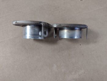
I then repeated the same process on the actual exhaust tube side: marking 0.23″ from the edge and then carefully cutting the tube with my Dremel tool.

I then test fit the trimmed cylinder #1 exhaust pipe.  The springs were still somewhat of a PITA to get back into place, which told me they had at least some decent spring holding action.  With the slip joint design, the pipes have to be turned at an angle from the mounting flange which stretches out the springs even more… so even though I removed 1/4″ out of the distance that the springs were holding, I don’t see any noticeable difference between the trimmed exhaust pipe’s spring holding power vs cylinders 2 and 4 on the other side (clearly I compared them).

After declaring cylinder #1’s exhaust pipe trim successful, I proceeded with trimming the height of cylinder #3.

I’ll note that the slip joint on cylinder #3 couldn’t really be classified as such since it was too tight of a fit and I had to use considerable force to get the flange side out of the tube side.  After I trimmed off 0.23″ from the flange side, I spent a good 10 minutes wet sanding the interfacing surface of the slip joint tube.  I then did the same on the inside of the exhaust tube side of the slip joint after I trimmed it, and also worked it back and forth a bit as well to ensure it was in fact a true “slip joint” in operation as well name.  All the slip joint fits on the other cylinders’ exhaust pipes were fine.

I then trimmed the exhaust pipes for cylinders #2 and #4 as well (right pic).  Here we also have both exhaust pipes on cylinders #1 and #3 in place too (left pic).

Some wider angle views of the trimmed exhaust pipes mounted onto the engine.

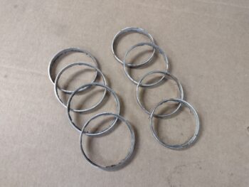
And a shot of all the trimmed 0.23″ rings I removed from the pipes.  I of course had to weigh them out of curiosity: 1.6 oz of weight savings!
Then came the real test: would the lower cowling fit with the exhaust pipes mounted in place?

The good news is that I was able to easily mount the lower cowling with the exhaust pipes in place, which I wasn’t before if the left exhaust pipes were mounted.

The bad news is that the left exhaust pipes are still too low and too close to the cowling to simply press forward with the engine and upper cowling install.  The bottom line is that I’m going to have to do a considerable amount of bottom cowling rework, about the aft 25% I’d guesstimate.  Since I will now have to engage in significant cowling rework anyway, part of my rework will be to open up the lower cowling center aft area to allow me to fit the flow guide of the bumble bee/Hershey kiss spinner in place.

I still have the lower engine mount bolts that need final torque and cotter pin (left side) replaced, which I will do tomorrow as well as start the initial sanding of the cowling and planning for just how I will modify the cowling to provide the proper clearance for the exhaust pipes and spinner flow guide.

Chapter 23 – Video Update

Today I spent a few hours filming, editing and finishing up a video that I’ve been working on the past few days that I wanted to get out before throwing myself headlong into working on the engine install.
This video covers the Fuel Injection Servo configuration and install, the air induction system and the RAM air can ops, including some footage of the new lever and actuator in action as they manipulate the RAM air can butterfly valve open and closed.

Tomorrow I have a bunch of errands to run, but I do plan on starting back to full time work on the engine install Saturday.

Pressing forward!