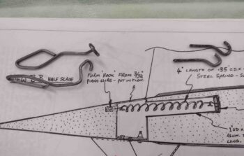
Chapter 20 – Winglets/Rudder complete

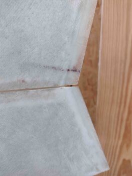
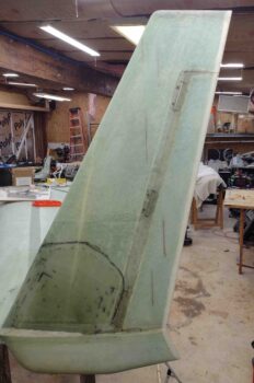
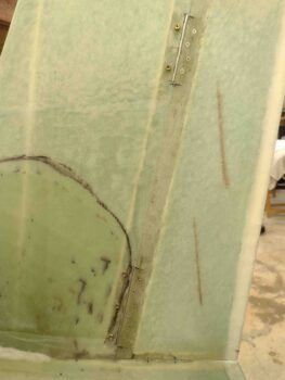
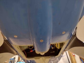
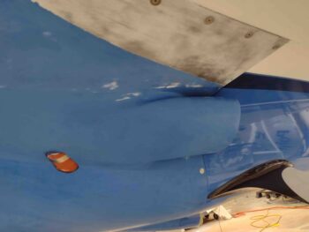
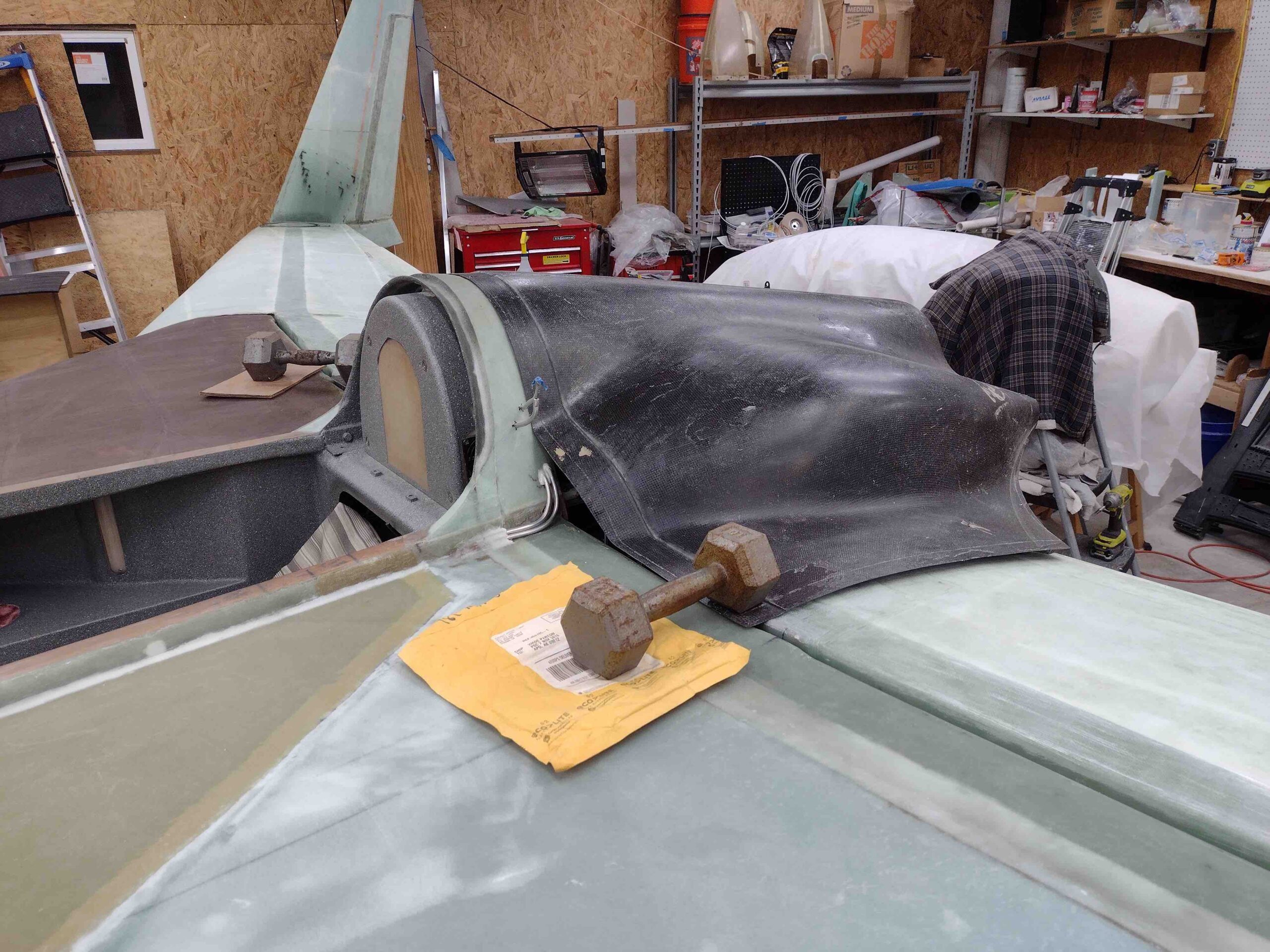
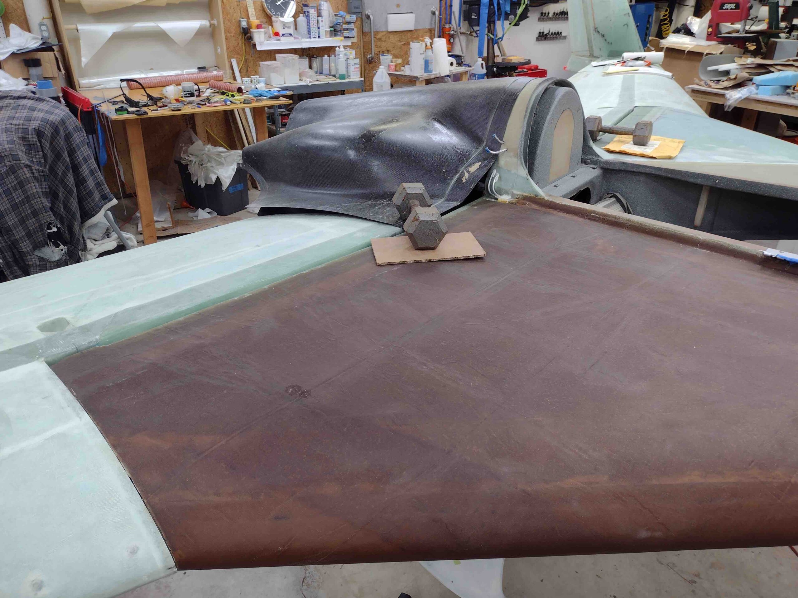
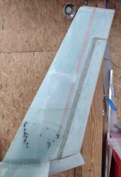
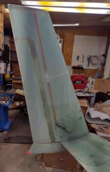
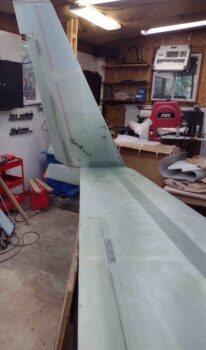
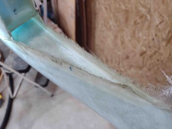
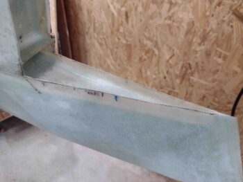
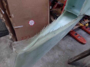
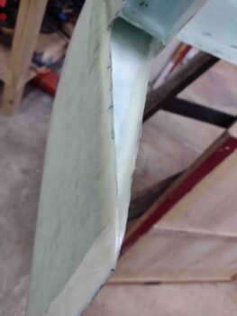
I started off today by pulling the peel ply off the single BID ply layup on the aft bottom corner of the right rudder.

I then razor trimmed and lightly sanded the edges.  It definitely reinforced the tweaked corner and did exactly what I hoped it would do.

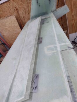
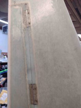
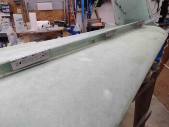
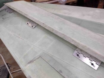
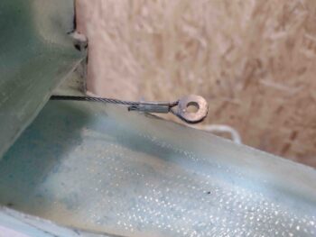
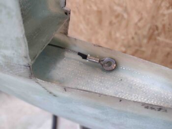
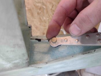
With my K1000-3s finally delivered, I removed the right rudder and installed 2x K1000-3s on the bottom hinge, and one each on the middle and top hinges, for a total of four (4) K1000-3s installed tonight (7 total installed overall).

I then reinstalled the right rudder with all the bolts in place.  I need to do a minor bit of tweaking on the right rudder alignment, as well as some judicious sanding, but overall everything looks really good.

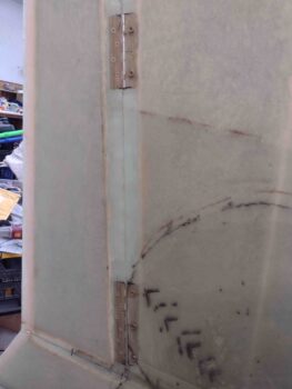
I then repeated the process on the left side rudder.  First I installed the 4x K1000-3s.

And then reinstalled the left rudder, secured with all the required number of bolts.

The left rudder is a lot less of a troublemaker than the right, so I have no notable squawks to report.

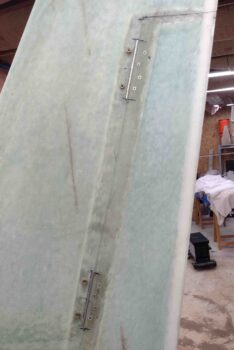
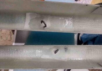
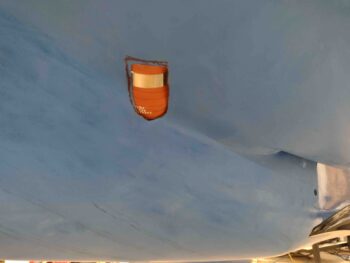
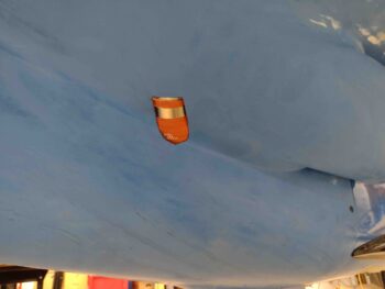
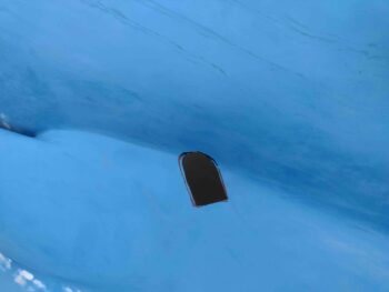
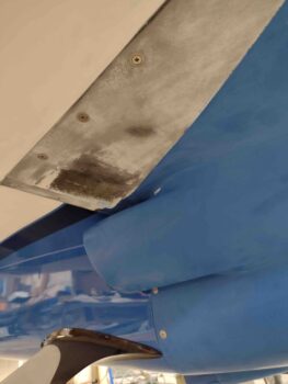
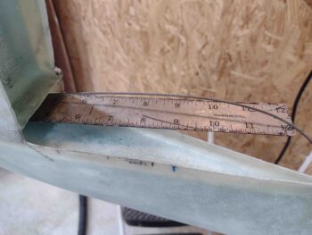
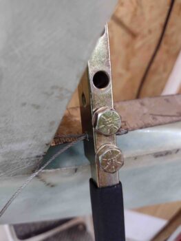
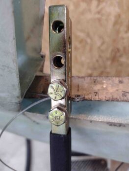
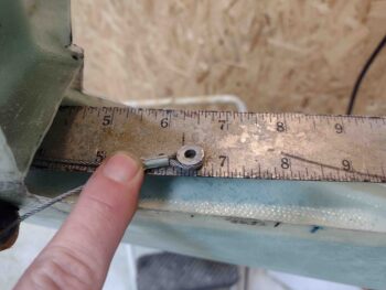
Here are closer up shots of the left rudder hinges with all the bolts installed.

Tomorrow will be a bit of a light build day, but I do plan on getting back to work on the engine and cowlings.

Chapter 23 – Engine & Cowling Plan

First off, I’ll let ya’ll know that I’ve had a cold for the last couple of days so I’ve been taking it easy as I assess my engine vs. cowling position issue.

Yes, over the last few days I’ve had a bit of an epiphany on my engine and I thought I would share it with you.

I have to face this issue down, and seriously determine and fix why I’m having any interference or just really tight clearances on my cold air induction pipe, my fuel injection servo, my exhaust pipes. my RAM air can, my mechanical fuel pump drain with my aileron control tubes, and now my prop spinner.

My initial assessment, again, is simple: something just ain’t right in Denmark…. the engine looks like it’s sitting in there fine, but all the indicators tell another story.

Ok, my troubleshooting skills may be slipping I guess.  But I think I’ve got at least two contributing factors.  My bad for not thinking this out better:

Here goes:  Mike Melvill had an O-235 and rigged his engine to be level at 2° nose high per plans… Or about 2° engine high at level longerons.

He then swapped his O-235 out for.an O-360, same mounts pretty much.  Cowling goes on the new engine which is still set at 2° high.

With a planned more powerful motor, I went with 1.4°… but am measuring even less.than that.  Probably not surprising since it’s been on the engine mount for 4 years now.

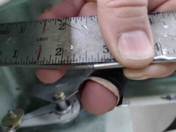
Now, my bird isn’t on a level floor, nor did I level it, so probably some slight variance.  But I’m measuring 1° on left, 1.2° on right as far as prop up in the back.  That equates to 0.2″ low on left and 0.16″ long on right if I were to bring it back up to 2°.  Significant when you’ve got close to zero clearance on the left exhaust pipes, and a lot of tight clearance issues with a myriad of other stuff.

When I was talking with Marco I wasn’t sure what angle I had set my motor at, but on my blog I noted that I set mine for 1.4º.  I used a .224″ spacer to get to 0.0º on the engine mount, while plans requires a 0.25″ spacer to get to 0º.

Looking at my buddy Dave Berenholtz’s blog, I noted he had a seemingly much tougher time getting the bottom cowl on than I did.  The major difference in our installs is that Dave had an O-320 motor installed on the plane to confirm that the bottom cowl needed to be angled back, or down on the back end.

In addition, Dave’s front top corners are about where mine are, which means the bottom of his cowl where it meets the bottom of the fuselage/firewall is most likely trimmed a good bit more than mine, angling his bottom cowl down on the aft end.  I would think that mounting the bottom cowl as he did caused issues on getting the sides lined up because the back end was actually where it needed to be.

I didn’t have the issues along the sides because I didn’t have my motor installed (huge error) and all seemed peachy keen installing it upside down.  Since, as I pointed out in my video, I only trimmed a max of 3/16″ off each side, most of it way less than that since it was a slight angle, I grossly underestimated how jacked up the cowling was in its design as far as NOT being anywhere close to plug ‘n play.

So…
1.  With my engine angled slightly down in the back more so than stock plans,
2.  Not confirming engine to bottom cowl fit with the engine in while installing lower cowling
3.  Resulting in engine sitting slightly low (some of that may be from 4 years on mounts) and cowling significantly higher compared to stock

I need to take some significant steps to mitigate my engine configuration issue.

#1 – I’ve been researching shims on engine mounts.  Apparently not that uncommon.  A number of reports of engines that start to sag or droop, and shims are used to get them back up to previous level.  I spoke with the Lord mounts folks and, with caveats and warnings to replace old mounts, I’m leaning seriously towards not replacing my mounts and shimming the bottom mounts to bring the engine back up to 2º.
#2 – After I shim the motor up, I’ll then assess its position.  I then need to be prepared for some possible major rework on the lower cowl to re-skin the aft area to open it up for exhaust pipes and spinner/flow guide.
#3 – I will work what I can on the exhaust pipes to possibly have them angled up just a scooch to add even more clearance.

I expect all this to add about a month to the build completion date.

Yep, mods can bite hard sometimes eh?

Chapter 20/23 – Odd & end tasks

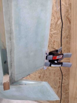
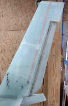
As I was finishing up one of the final small tasks I had on my Chapter 20 to-do list, my buddy Brian Ashton called from Alaska… he’s the guy building a twin Long-EZ.  As we talked, I was making light of the fact that I had hauled these winglets around for 10 years after making them, and nary a scratch on them.  And then within the first hour of setting them in place for install the right one got away from me and of course crunched the lower aft corner… which is of course now the lower aft corner of the rudder.

It was a slight crease, but one that needed some tending to.  I laid up a ply of BID on it, peel plied it and then clamped both sides of the layup and rudder to ensure it cured straight and aligned with the rest of the rudder TE.

Layup complete.

My K1000-3 order apparently was frustrated cargo with USPS and got sent back to CA.  Apparently Aircraft Spruce in GA doesn’t carry stock anymore because I seem to get a lot from CA.  They said that my zip code was incorrect, although I pulled my address off a list of maybe 30 same addresses in the shipping address block… oh, well. Weird, frustrating and the end result is no K1000-3s until I re-ordered.  BUT . . .

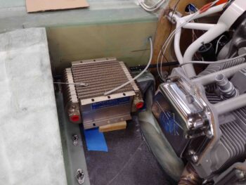
Knowing that I wanted to add a bracket to support the rather hefty oil cooler when I take off the bottom cowling, I ginned up a loose design to get an idea of even more hardware I would need.  Moreover, I wanted to ensure I accounted for all the oil line fittings and angles I would need to get the oil cooler installed.  All before re-pulling the trigger on another ACS order.

Now, Mike Melvill has his oil cooler installed with the rows going parallel to the CS spar.  So I started there.  I quickly realized that I would need 90° elbows, which A) I try to stay away from reported reduced flow (does it really matter? you got me…), but moreover, B) I have zero on hand.  Plus, the space would be tight between oil cooler lines and the aileron control tube, which I want to avoid.

I then tried setting the oil cooler in, with rows parallel to the CS spar, with the hose fittings facing aft.  This was not much better.  It would require a LOT more oil line hose and would still most likely require at least one 90° fitting.  Although I am keeping it as a viable option due to my inline external Vernatherm needing someplace to exist in this engine compartment area.

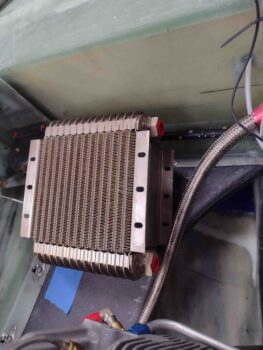
I concluded that the best option was turning the oil cooler 90° so the rows were perpendicular to the CS spar, with the connection fittings facing the inboard forward engine area. Again, I still have to account for my external Vernatherm mounting spot, but this looks like the best spot.  I will note because the extended curved side of the cooler, I may need to tilt it up bit at the front to ensure clearance with the left aileron control tube.

I decided to ask Marco if he had any pics of his oil cooler install?  What direction did his oil cooler fittings face?  I sat down on my step stool immediately aft of the engine to send him a text, and while awaiting his reply took a good look at the engine and bottom cowling.

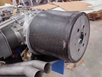
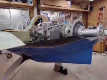
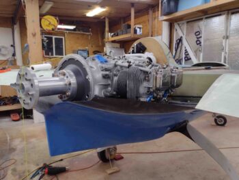
I noted to myself that it appeared with the current position of the engine along with the untrimmed aft lip of the bottom cowling, that there was no way my Catto Hershey Kiss spinner flow guide could be mounted in place.

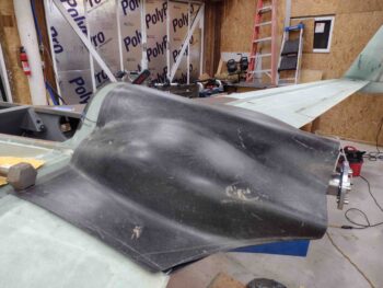
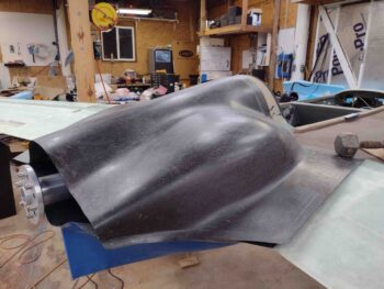
I went into the house and quickly grabbed the flow guide and tried to put it on.  And I was right:

I determined that it would require trimming the bottom cowling aft lip forward at least to the edge of the top of the boat tail.  Very probably even more than that.

In doing a bit of snooping around online and in CSA I learned that Mike Melvill did in fact trim his bottom aft cowl lip back to just a small (maybe 1/4″) edge left over the top of the boat tail, and also that he had no flow guide installed on his bird.

Still, my gut feeling is that my engine is sitting (angled) just a tad low while my cowling is naturally just a tad high.  I’m going to do some more research tonight to get some more info on this and try to do a course correction before I proceed with any major cowling modifications.

BTW, Marco’s oil cooler fittings face inboard, like my last pic of the oil cooler shows.

Chapter 20 – Rudder springs installed

Today I installed the rudder return springs into each winglet and rudders. I didn’t get any pictures of that, but I did make a video that shows the result of installing these springs.

Tomorrow I’ll press forward with the upper and lower cowling installs, as well as engine component installs as well.  If the K1000-3 nutplates arrive tomorrow I’ll install those into the rudder hinges also.

Chapter 20 – Rudder return springs in

I’m going to start the blog off today by thanking and giving huge kudos to Ary Glantz for catching something that I think 99% of us builders miss.  You can read the detail here on his blog.   Moreover, since Ary did such a great job covering it, I will simply quote his words below, which is the lion’s share of the detail in his summation of what Jim Weir of RST engineering —the guy who designed the antennas and created the kit that I’d think over 90% of all canards use— had to say about our rudder return springs (indirectly):

Ary:
***** “Ok, so now to install [the rudder return spring] inside the winglet. The “high performance rudder plans” says to install the assembly at WL25. HOWEVER, the RST-2802 antenna manual (the Holy Grail manual that explains everything you ever wanted to know about canard airplane antennas) says “If there is a piece of metal more than an eighth of a wavelength long within a quarter wavelength of the plastic plane antenna design, the antenna performance will be degraded”. They go on to say “with the classic dipole ‘rabbit ears’ design, metal close to the center of the antenna where the ears come together has practically zero effect. Metal out at the tips of the ears has a tremendous effect.”

Hmmmmm… but the High Performance Rudder plans tell us to install a blob metal object at the tip of the antenna! Nooooooooo!!! Why!!!!?!?!!” *****

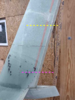
Here’s W.L. 25 on my bird, about an inch down from the bottom tip of the antenna.  So “why?” indeed.

My question was if essentially every builder and every Long-EZ that I know of —past, present and recent— installed the rudder return spring per plans, why are there no complaints on radio performance or range? l searched all the CSA articles and didn’t find any instances of issues or complaints.

I also read the RST-2802 manual firsthand and found the answer.  As Jim points out, and I”m paraphrasing, if you start out at a certain baseline capability, and it isn’t awful, with nothing to compare it to how could/would you possibly know or ascertain experience-wise how good it has the potential to be?  It’s simply a matter of optimization, not just if it works or not.

With Ary’s reminder of Jim’s words of warning, I decided to simply move my rudder return spring up much closer to the center of the comm antenna on each winglet.  I did want the rudder return spring near a “hard point” so I went a few inches above the center hinge position, which turned out to be about 2″ below the center of the antenna.  I think I’m safe in this location… obviously and comparatively much more optimized than putting it in the plans position.

The resulting final delta is 25″, moving the rudder return spring assembly up from W.L. 25 to around W.L. 43.

I’m guessing that the W.L. 25 position was based off the original plans squarish rudder, and with so many people at one point doing conversions to High Performance Rudders vs new builds they simply left the rudder spring in the original position. Also remember that these antenna configurations didn’t come into play until well after the first Long-EZs were built, so the W.L. 25 located rudder return spring assembly predates the Jim Weir winglet-located comm antennas. Just my thoughts, I could be wrong of course.

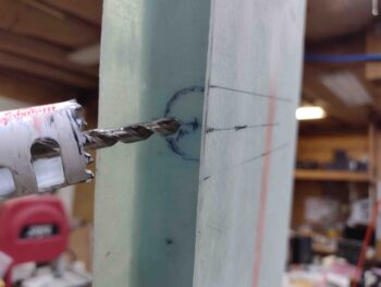
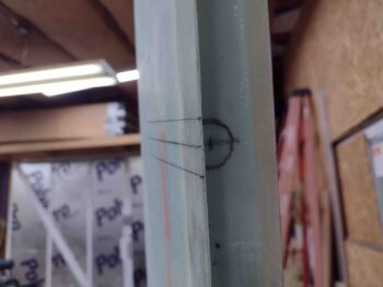
Once I had the positions marked, I took my 1″ hole saw and cut just the glass inside the winglet rudder hinge pocket.

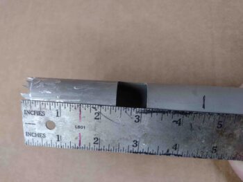
I then found my old lopped off piece of 1″ OD 6061 tubing that had been the original plans length left elevator tubing.  It had some left over glass and epoxy on it that I scraped off, and I then notched the end with the Dremel to make some saw teeth.

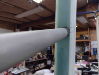
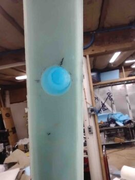
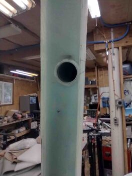
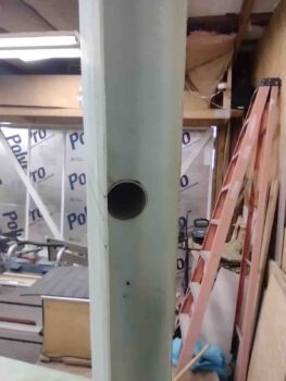
I then carefully used my makeshift hole saw to make the pocket for the rudder return spring tube, being very careful to avoid damaging the antenna copper foil tape… as you can see here on the left winglet.

Again, on the left winglet, I cleaned out all the foam to ensure a nice 4.5″ deep pocket, also ensuring that the antenna was not damaged in the process.  I did the same on the right side.

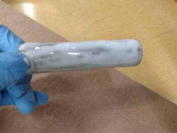
I then whipped up some micro and slathered up the inside foam of each winglet cleared-out rudder return spring tube shaft.  After cleaning them with acetone, I then slathered up each rudder return spring tube with miicro and stuffed them into the winglets.  Although not shown, I also used a nice dap of flox on the wood plug at the front end of the tube before installing them.

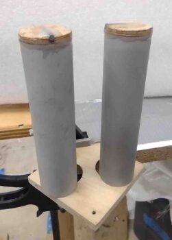
Here we have the rudder return spring tubes micro’d and floxed in place in both the left and right winglets.

While the rudder return spring tubes cured in the winglet pockets, I then turned my sights on installing the rudder side rudder return spring hooks.

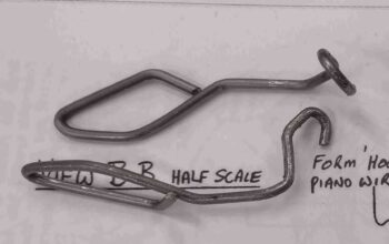
If you remember, I made my hooks so that they actually go into a hole on the face of the rudder hinge pocket, before then making essentially a 90° turn to lie somewhat flat against the interior side glass of the hinge pocket.  I also made them long enough and canted the hook at an angle that when I install them into the hole, I pivot them to lock the somewhat diamond shaped hook body up against the interior skin on the opposite side of the rudder.

Since the plans aren’t overly clear on how these are shaped, I got the idea for my hook design from how Dave Berenholtz made his (thanks!) after I pondered on their function a bit.

I then made a hole just a hair smaller than the widest part of the “diamond” part of the inside hook body.  For the left rudder this was a 1/2″ hole, for the right around 0.46″ diameter hole.

Given how my rudder-side rudder return springs physically lock into place inside the rudder hinge pocket, I wasn’t squeamish about using the decent amount of flox and micro I had left over from the winglet rudder return spring tube installs.

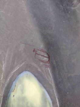
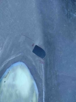
However, just to make sure all was secure, and cover the rather large hole I made on the face of each rudder hinge pocket, I did layup a small ply of BID around each hook.  I then peel plied each layup.

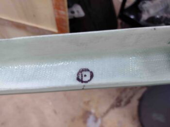
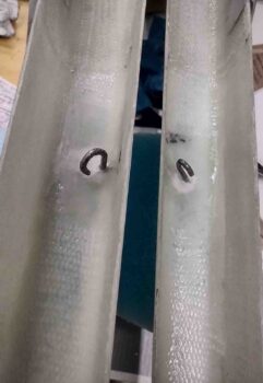
Very much later tonight I pulled the peel ply and grabbed this shot of the rudder-side rudder return spring hooks.

It was too late to install the rudders and test out my spring action, plus I wanted to give the micro, flox, and layups a good overnight cure before stressing them… so tomorrow I’ll test out the springs.

With the rudder return spring assemblies installs complete, I called it a night!

Chapter 20 – Making rudder hook plugs

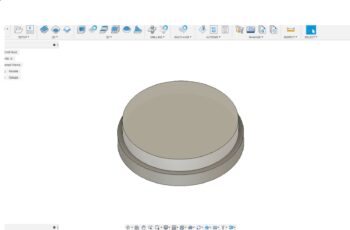
Today I started off reacquainting myself with Fusion 360 CAD software by drawing up the Rudder Return Spring Hook Plug as outlined (or mentioned… ahem!) in Chapter 20.

Drawing up the hook plug really wasn’t that challenging, but getting back into the CAD side of Fusion 360 to machine these things took a little bit of relearning.  I then had to do some tweaking on the milling machine for a couple of hours to get it back online and ready to spit out some chips.

Before I actually started machining the Rudder Return Spring Hook Plug out of 1/4″ Birch plywood, I took a break for about an hour to take pics and respond to Clinton regarding the exhaust pipes fit in the lower cowling.

I then got back to machining my rudder return spring hook plugs, as you can see in this video:

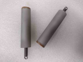
Although I added these pics to the end of the video, here you can see I floxed the hooks into the wood plugs, and then with some leftover flox I floxed the wood plugs into the ends of the rudder return spring tubes a little bit later.

Being lazy, er, uh, efficient, I went ahead and put the springs onto the hooks and ran them into the tubes so I wouldn’t have to fiddle with them later.

Yep, these few pics may not make it seem like a very long or productive day, but I can assure you it was both!

Chapter 23 – Lower cowl fix actions

I started out today by creating a notch on the right side of the lower cowling, just aft of the armpit intake, to create clearance for the engine’s aft right cold air induction pipe.

Of course this was NOT a one and done task, requiring iterative trimming of the right side lower cowling notch.  Here we have the notch edge marked for further trimming.

And here we have yet another round of trimming on the right side of the lower cowling to again allow clearance for the aft right cold air induction pipe.  This however, was not the final round of trimming.

Much later, I did the final trim on the cold air induction pipe clearance notch.

All the above notch creation allowed me to FINALLY fully mount the lower cowling with every CAMLOC installed.  Here’s the left side . . .

and the middle bottom CAMLOCs, and finally the right side.

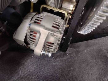
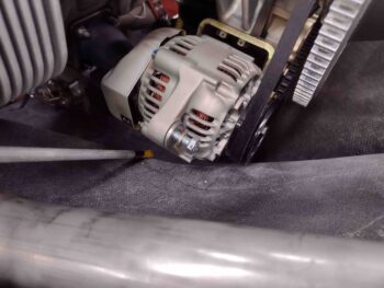
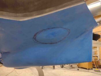
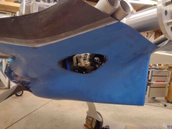
Again, since I’ll be tweaking the lower cowling on the right side, I’ll be removing the bump on the aft left side of the lower cowling for the alternator.  I started the “bumpectomy” by drilling 3 small holes at the vertical outboard left edge plane of the alternator (pic on the left).  To be clear, the “corner” break at the lower vertical to upper horizontal seam (right pic) will be left in place.

Here is the alternator bump on the aft left side of the lower cowling, marked for removal.

Which I did when I made the final trim on the right side for the aft right cold air induction pipe.

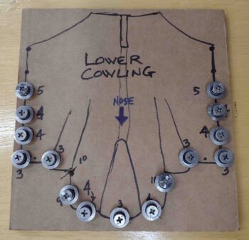
I’ll note that before I remounted the lower cowling this last round, I went ahead and made up a hardware card to allow me to keep track of all my CAMLOCs and screws.

Part of my efforts to correct and tweak all these engine components vs lower cowling interference, found me on the phone with Don at Airflow Performance in regards to swapping out my 85° elbow for a 90° elbow.

I also spoke with Allen at Precision Airmotive regarding clearance issues and configuration of the Silver Hawk EX fuel injection servo.

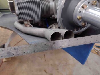
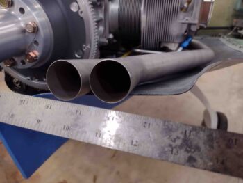
Finally, I spoke with Clinton at Custom Aircraft, who made the exhaust system for my bird.  In my discussion with Clinton, we came up with an initial game plan for me to send the exhaust pipes back to Clinton for him to cut and re-weld at the proper angles to have acceptable pipe clearances as they exitf the cowlings.

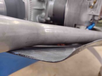
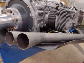
Here is another shot of the right exhaust pipes’ clearance with the lower cowling.

Although at angles, these pics show both the clearance of the exhaust pipes with the lower cowling, and also the left-right position so that the midpoint of each pipe pair is about 9″ from the engine centerline.

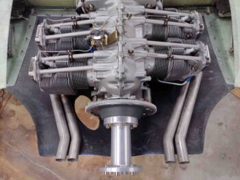
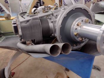
Here is a shot of the engine and exhaust pipes from above.

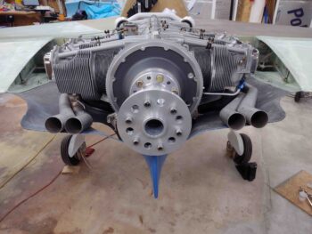
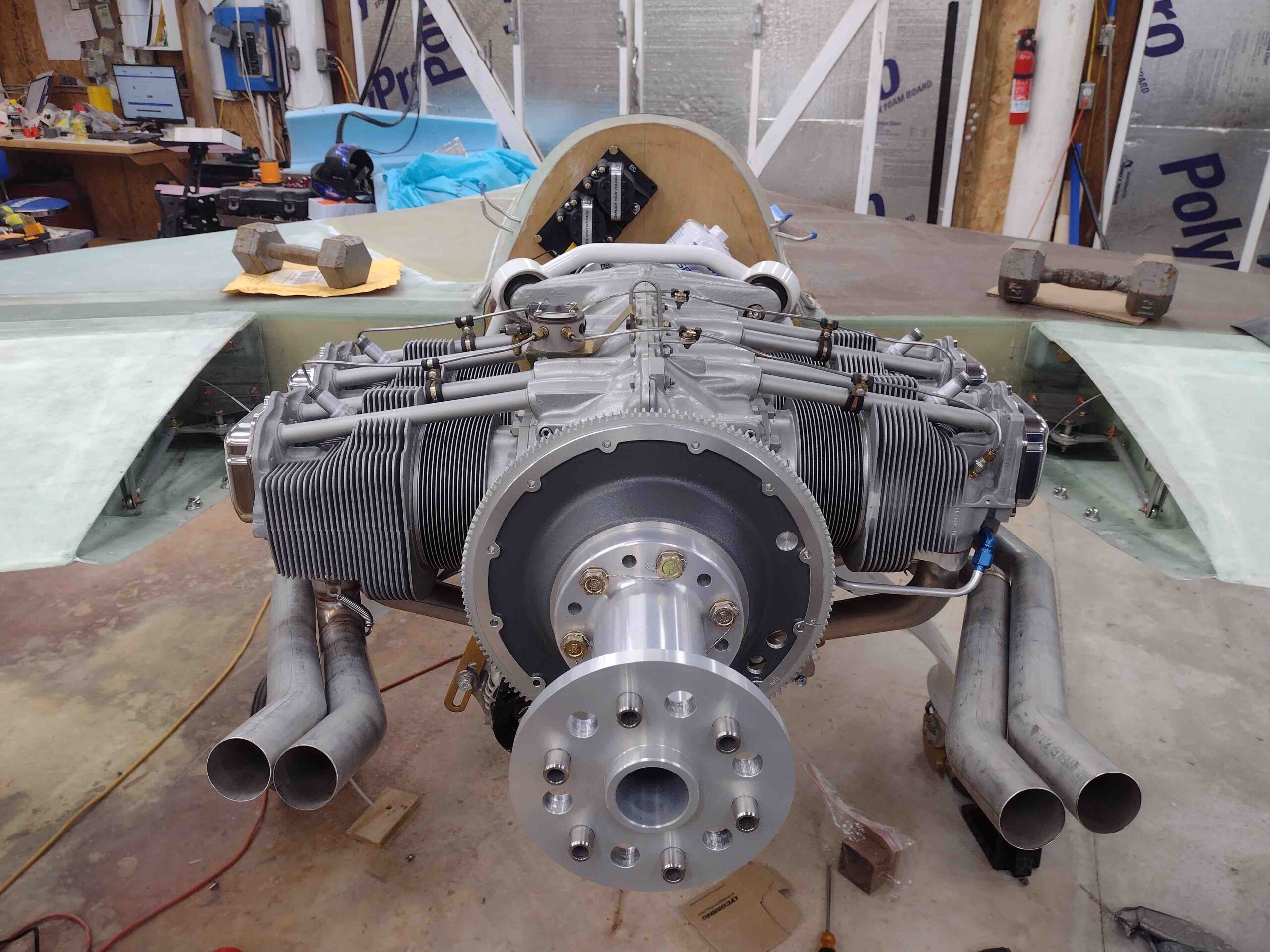
And from behind… I took these shots specifically at Clinton’s request to allow him to evaluate my exhaust pipe situation.

Tomorrow I plan on pressing forward in working both the lower cowling vs engine component clearances, along with some final winglet/rudder tasks.

Chapter 23 – Cowling: bad to worse

Let it be known that I’m not trying to sound like Chicken Little or be overly melodramatic on my blog post titles… it just really is both surprising and perplexing to me how relationally off the cowlings can be in regards to the engine components.

Now, to drop yet another movie reference, “With great power, comes great responsibility” Peter Parker’s (aka Spiderman) uncle.  So, with high engine power derived from cold air induction, RAM air and fuel injection… yes, there is bit more to contend with stuffing all this into a Long-EZ cowling.  Thus, am I allowed to state: With great engine power comes great challenges… ?!

Now, to be fair, I thought I could cheat with stuffing an O-320-sized motor into cowlings specifically designed for an O-360 and get away with adding all these goodies… but I got caught! Big time.

Starting off this morning I wanted to verify that my engine was sitting in the center of the lower cowling… as you can see below it clearly is.  At least within an acceptable tolerance (I ensured that the gap issues below were mitigated when I did this plumb bob exercise).
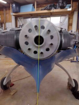
A couple more shots of the lower cowling partially installed around the engine.

The issue is that I have gaps on both inboard corners, with the right side more so than the left… at about 1/2″ (blue arrow and pointer).
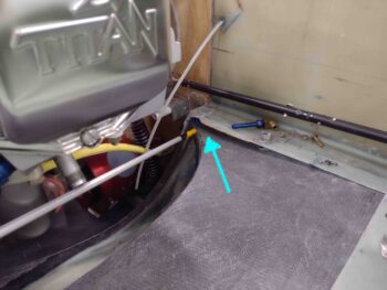
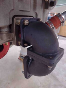
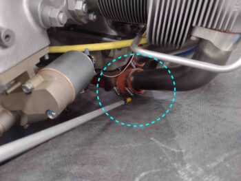
At first I chalked it up to the fuel injection servo being too low, but then lo and behold I discovered that the right side cold air induction pipe coming out of the plenum into the aft cylinder intake manifold was keeping the cowling from moving upwards the last 1/2″.
Before I delve into any more issues, let’s take a brief moment for some feel-good pics… here is the upper cowling set in place to get a general idea of how it will look once mounted.

And a couple shots of the upper cowling looking over the strakes….

And finally, some shots of the shoulders, where the cowling “corners” come forward onto the CS spar and strake.  If the left side (right in pic) looks a little higher than the right, that’s because it is.  Please refer all design questions or comments to Mike Melvill… ha!
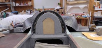
Ok, back to the issues at hand.  I ran out to have a quick lunch with Jess, but before I left I grabbed this shot of the fuel injection servo mounted straight to the aft side of the Superior Cold Air Plenum.  I wanted to see how it fit back there in case I need an optional place to mount it due to limited space.  It actually fits fine.  One challenge would of course be ensuring that I could get air U-turned back into the FI servo (nose is to the left ← ).
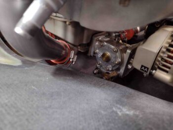
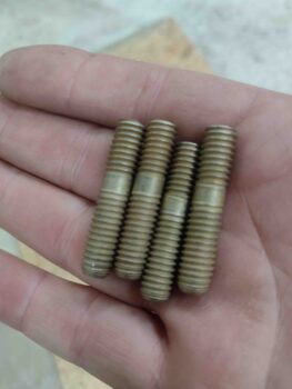
On the way back from lunch I stopped off at an auto parts store and picked up a stud removal tool.  Nothing else was working so I hoped this would do the trick.  Here I have it attached to the stud from hell that just would not budge a micrometer.
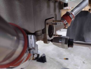
And voila!  It took the stud right out… very handy little tool.
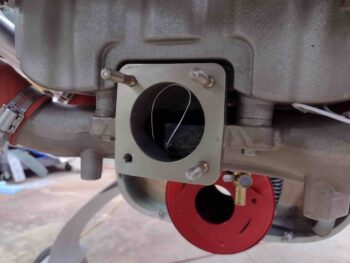
I then proceeded to take all the long studs out of the cold air plenum.  I will say one detractor about the stud removal tool is that it bites so hard on the stud that it ruins it for any future use.  Oh well.
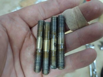
My camera (phone) ran out of memory so I didn’t document installing 3 of the 4 studs.  Ok, wow.  Those shorter studs were way harder to install than removing the stubborn long studs with the handy, dandy stud removal tool.  No tool to put these things in, just trying to lock 2 nuts to each other.  I simply couldn’t get them in as far as wanted to, but far enough to meet the requirements [#4 is in the freezer and when I get a chance I’m going to really hit the plenum face hard with heat before threading in the frozen stud… let’s see how it works eh?]

I then figured if I was going to stress test the lower cowling for space and clearance of all things engine-related, then I needed to lay all my cards out on the table….  so I grabbed the exhaust pipes and installed them in place.
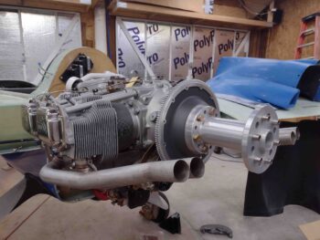
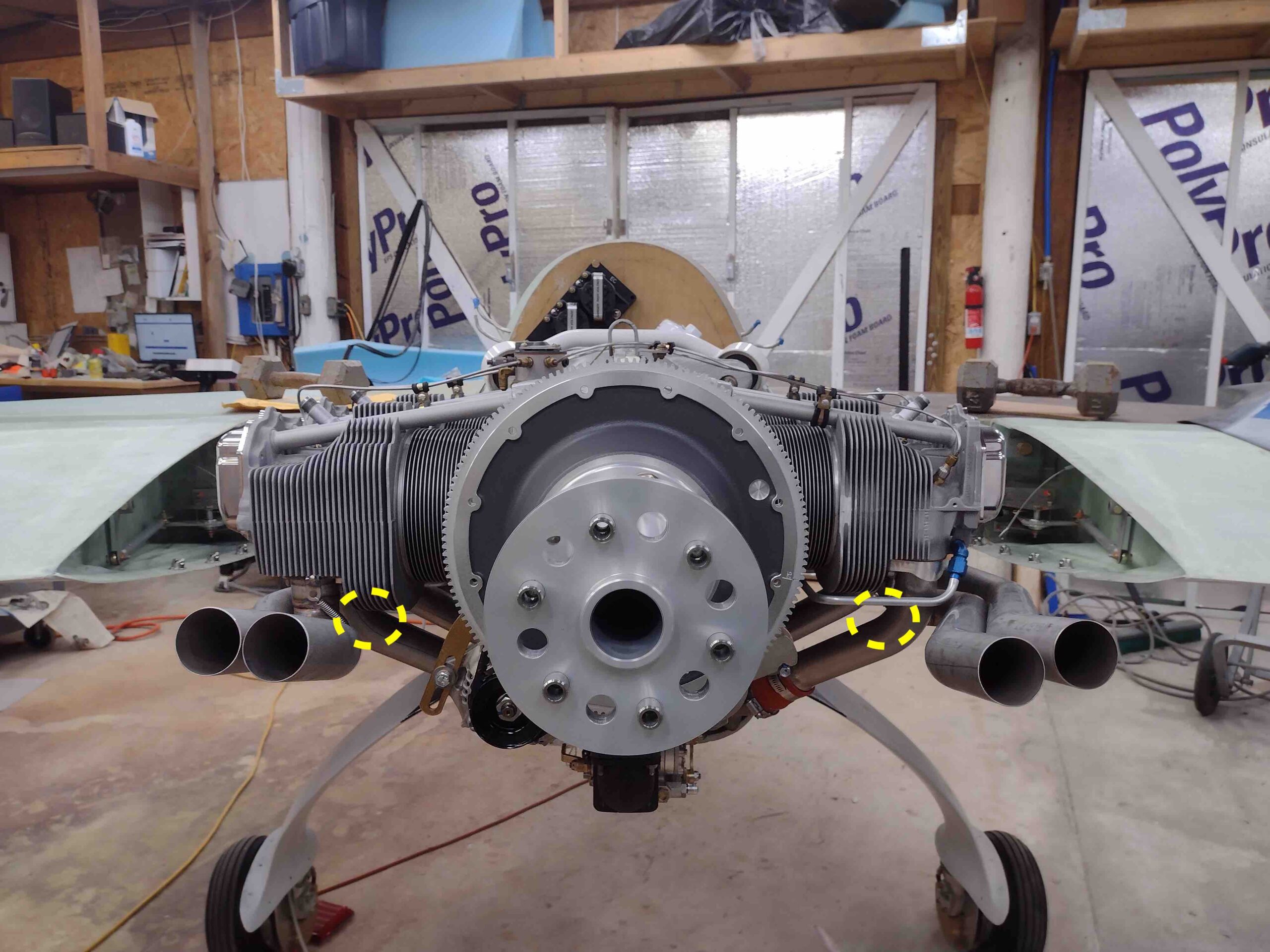
Here’s some shots from straight aft of the engine.  The yellow dashed circles denote about where Mike Melvill’s inside exhaust tubes are located.  Mine are significantly outboard of his.

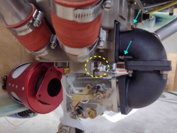
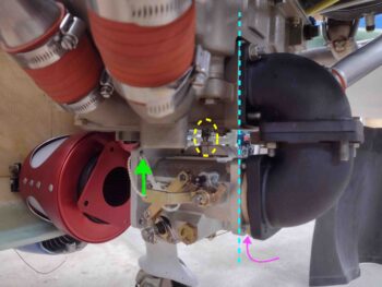
With exhaust tubes in place, I then set added some washers (magenta arrow) to the bottom of the 85° bottom elbow to get it as close to a 90° elbow as possible.  Note the blue dashed line.  This of course had the effect of raising the entire fuel injection servo up a bit, especially the front end (green arrow).  Finally, I wanted to ensure that I still had decent clearance for the fuel spider feed line connector on the top of the FI servo (yellow dashed circle)… the space was tight, but looked ok.
One last shot of the exhaust pipes and fuel injection servo before the cowling went back on.
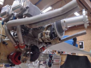
Ok, having the exhaust pipes mounted after all these years is admittedly pretty darn cool.  However, what is NOT cool is that the exhaust pipes are essentially laying on the inside surface of the bottom cowling.

I put a piece of 1/4″ plywood under the FI servo, so at this point I had about 3/8″ of clearance minimum under the servo, I’d guesstimate.  But the with the cold air pipe of the aft right cylinder blocking any upward movement of the cowling, I was at a standstill assessment-wise until I could start turning some of these variables into constant data points.
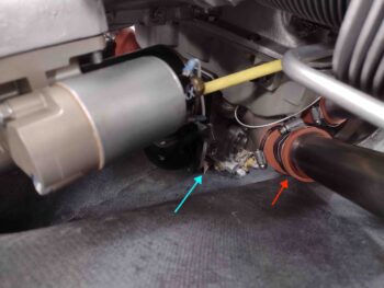
As I stared down the lower cowling and engine from all different angles to understand the issues and possible remedies, annotating it all, I accepted the fact that I was going to have to put a hole in the right side of the lower cowling to allow space for that cold air induction pipe.

On a slightly different note, remember that Mike Melvill put an O-360 motor in this cowling, which IS a bigger motor.  That means some things were naturally in different positions and different proportions than my engine configuration.  One such thing is the bump out on the cowling for the alternator.  It is just way too much for my more diminutive 40-amp B&C alternator.
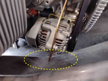
I decided that if I had to Frankenstein my lower cowling (thank goodness I never went to final paint on the darn thing!) that this repugnant bump —which most certainly would have disturbed my nice airflow to the prop!— had to go.

Yep, I am going to perform a bumpectomy and get rid of this blight on my cowling.  While I try desperately not to add another one on the right side.
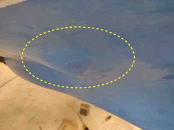
So… with all this head scratching and emotional gut punches in dealing with so many darn clearance issues between my lower cowling and engine, it was time for a glass of red and a late dinner!
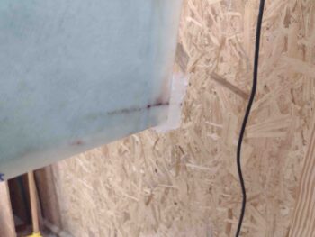
Chapter 20/23 – Good day, bad day!

Today was a good day in regards to the rudder installs… not so good for the engine components configuration.

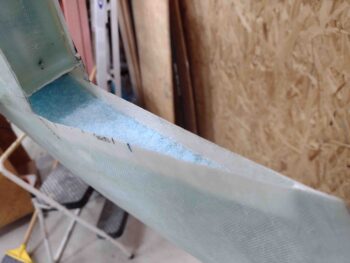
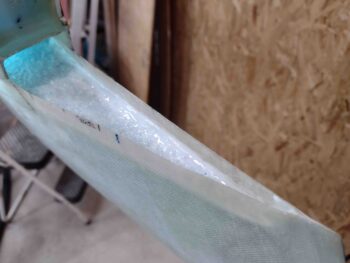
First, here is a shot of the right winglet’s Internal Bellhorn arm pivot channel. Yes, there is some blue foam peaking out from under the micro… a future project to jam a ply of BID up there.  Not a high priority nor does it make it un-airworthy.  Pressing forward.

My plan starting off is to have the right wing root rudder cable situated as far outboard as possible…

with 6.25″ of cable from the aft corner of the rudder conduit opening of the wing exiting out of the Internal Bellhorn channel.

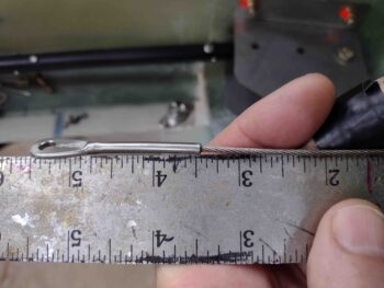
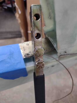
I then swaged a thinned AN111-C3 onto the right rudder cable at this 6.25″ mark.  I’ll note that unlike my test swage on the left side, I left the cable long to allow me to pull it tight around the AN111-C3 bushing.  This worked infinitely better than pre-cutting the cable.

My final length showing out the wing end was 6-3/8″… however, the wing root rudder cable connector actually slid into the conduit a little bit (see below bit).

I trimmed off the excess cable and then put a piece of heat shrink over the trimmed cable.

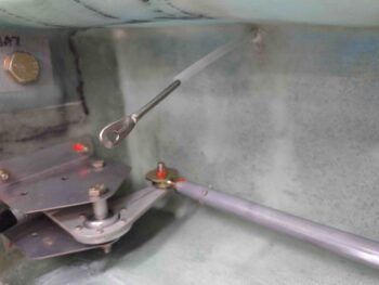
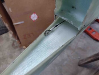
And attached the Internal Rudder Bellhorn to the right rudder cable.  Note that I have plenty of rudder cable accessible to easily attach the Bellhorn arm.

Here we have the right rudder installed with the Internal Bellhorn attached to the rudder cable.  In pic #2 the rudder is kicked out full swing by pulling the rudder cable at the wing root.  Success!

With the right rudder at neutral, the exposed rudder cable exiting the wing root rudder cable conduit is just under my planned 3.5″.

I then repeated the same process on the left rudder.

Here the left rudder AN111-C3 bushing is swaged to the left rudder cable.

Here we have the AN111-C3 bushing swaged and heat shrunk to the left rudder cable.

I then installed the left rudder and tested the rudder pivot outboard by pulling the cable inside the wing root.  Success again with the rudder pivoting out full swing by only manipulating the rudder cable.

Now, although I targeted 6.25″ of cable length exiting the left winglet’s Internal Bellhorn arm channel, for some reason with the rudder at neutral the amount of rudder cable exiting the conduit is 2-5/8″.  Not really an issue since I have plenty of cable to allow me to easily mount the rudder… just a bit odd that it ended up like this.

Ok, rudders are good… some minor tweaks required of course as par usual. No biggie.

But boy did I hit a number of brick walls as I started work back on the engine.  First off, the studs on the cold air plenum are simply too long to work.  Technically I could add spacers to the 2 top studs and make them usable… but the bottom 2 studs won’t even allow me to get a nut on there to secure the air induction 90° elbow.

I had planned for this, so quite some time ago I ordered shorter studs from ACS.  However, these longer studs are simply FROZEN into the cold air plenum and are not coming out (yet!).  I tried the double nut method, thread penetrator, heat, all the above… nothing worked.  I talked to the local auto parts store and even my Long-EZ building buddy Chris Seats.  I finally ended up ordering a somewhat expensive stud remover tool off of Amazon as a last resort.

With the long studs still in place, I pressed forward with installing the required air U-turn elbows for my configuration, which you can see below: Filtered or RAM air enters system via RAM air can which will be connected to the fuel injection servo with a short length of SCEET tubing.  Then air exits fuel injection servo and enters elbows for U-turn into the cold air plenum, which then distributes air to the individual cylinders.

Even though the long studs were in place, I could press forward with the interim install to allow me to put the bottom cowling on to facilitate the top cowling install.  Right?!  Wrong!

The cowling would not seat properly due to the fuel injection servo sitting about a 1/2″ too low.  I do have some wiggle room, but that means swapping out (read: buying) my bottom 85° elbow for either another 90° elbow, or perhaps even a 95° elbow.  I’ll do more configuration tests over the next day or two to figure this out.  Plus, there are threads showing on the top 90° fuel elbow (yellow circle) which may allow me to thread it in deeper into the servo body.  Again, a fair bit more research required here to finalize this specific install.  And, again, as per usual…. space is TIGHT.

Time for a drink and some dinner!
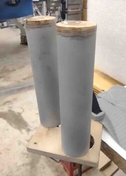
Chapter 20 – Lower winglet final glass

I started off today by doing final prep for the right lower winglet aft side trough, the area that sits below the rudder.  To be clear this layup also links the aft lower winglet to the Layup #3 glass.

I then whipped up some wet micro and applied it to the blue foam.  I also created a micro fillet at the edges of the blue foam for a transition to the glass sides.

I then laid up the prepregged 2 plies of BID into the lower winglet trough.  Again, this layup goes a good ways into the Bellhorn pocket and overlaps both onto the Layup #3 glass and the lower inside walls of the upper winglet, tying this lower winglet layup to the existing structure in multiple ways.

Jumping ahead, a few hours later I razor trimmed the layup.

I then did the same thing on the left side.  I will note that when I was thinning down the foam inside the Internal Bellhorn pocket I inadvertently dug into into the foam and knocked a decent sized divot out of it.  Thus, I need a big blob of dry micro to fill in the void I mistakenly created.

Again, jumping ahead quite a few hours, I razor trimmed the layup.

I then spent a good little bit of time forming the left and right rudder return springs from 3/32″ piano wire.  As anyone who has attempted to work with this wire, it is not a task without a good bit of effort . . . a vise is definitely required.

Not shown is the work I did to take the raw cut end of each spring and create a loop 90° to the spring rotation to allow attaching the spring to one of these hooks.

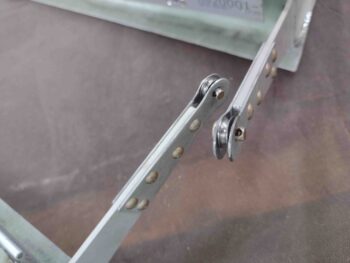
I then spent another good little bit of time using the Dremel tool and then hand file shaving down around 0.010″ off the inside of each arm end of the Internal Rudder Bellhorn that holds the AN111-C3 bushing, from 0.05″ thick down to around 0.04″ thick.  To still allow free movement of these bushings, I also shaved the sides of them down as well by about 0.010″ off each side with the Dremel tool.  All this Dremel and hand filing work —although not necessarily pretty— now allows free movement of the AN111-C3 bushings in the end of the Internal Bellhorn arms.

Looking back over the day’s work it doesn’t seem like I really go a lot done, but much of it was very time consuming tasks.  So, with that, I called it a night.