Chapter 21 – Bottom skins attached

I started out today with one of my occasional selfies to let the FAA know that I’m actually building this bird.  Plus a decent shot of the progress on the strakes, albeit today was a slow build day.

I then finalized the BID prepreg for the final small layup on the front right strake opening that connects the bottom inside skin to the fuselage sidewall.

First pic is the peel plied layup.  Second shot is quite a bit later when I pulled the peel ply.

I also did the edge along the GIB strake opening from the inboard top surface of the right strake bottom skin, with 1 ply of BID overlapping into the fuselage about 1″ onto the sidewall.

Again, the first pic is the peel plied layup and the second pic is with the peel ply pulled. I will say going around that 90º corner caused the glass to lift ever so slightly in some areas which will require me shooting it up with some wet epoxy after I finish laying up the final ply of glass on the curved, half-moon portion of the fuselage sidewall strake opening just above and overlapping slightly on this layup.

Lastly, I spent a bit of time dismantling the support clamps, wood strips, shims, hot-glued tabs, etc. to show the attached/floxed/glassed right strake bottom skin core.  These bottom strake skins attached not only officially give me fuel tanks, but are clearly significant milestones for this build.

Tomorrow I’ll continue with strake / fuel tank tasks and will then transition into the final nose build tasks and wing aileron glass/install before I flip this bird to sand, shape and glass the bottom external strake skins…. and much more.

Chapter 21 – Right bottom skin install

I started out today by removing the clamp that secured the left sump tank vent tight up against the fuel tank (fuselage sidewall) interior wall.  The layup was successful so I’m calling this task complete.

I grabbed this shot to show how I trimmed down the flox that squeezed out just a bit along the aft T-Hat structure edge along the CS spar.  As on the left side, this flox actually covers about an 1/8″ of the protective tape so it needs to be trimmed a bit to both even up the line and to allow for the protective tape to be removed completely.

This obviously didn’t have anything do with attaching the lower skin on the right side, but it needed to be done to technically call the right side T-hat structure complete.

To avoid the problems I had on the left strake lower skin attach where I had to very gingerly balance the pressures out of all the spreader clamps —that were applying bottom-up force— that was just a complete time suck, I figured I just needed to assist gravity a bit in my quest.  So I first chucked over 130 pounds of weight into the back seat.

And hung another 25-pound weight off the end of the CS spar.  I figured I could go heavier on this weight, but I didn’t want to go round up a 45-pound weight and mess with hanging such a big weight out here.  Also didn’t want to stress the spar any more than I had to.

The trick, I felt, heading into the right strake bottom skin attach was to know that I needed to apply pressure quite judiciously to the bottom skin core to keep it tight against the strake structure.  With that knowledge in hand, assisted by a heavier fuselage and CS spar, I pretty much confirmed that this was the deal when I attached the right strake bottom skin.

I then got busy actually attaching the right strake bottom skin core.  Again, it is amazing how much flox is used to secure this skin core to the bottom of the strake structure.  Also, since I’m fighting gravity again, I put the flox inside my marked “floorpan” lines on the actual top surface of the lower skin and then simply “lifted” it up in place.

I employed the same method on the left side, although I don’t think I got a shot of it. Moreover, mixing and applying this much flox took nearly an entire hour just in itself.

After a mad dash of getting the right bottom skin core in place, clamping and wedging it so that as-equal of firm pressure was being applied all the way around, I then got busy wetting out and laying up the nearly 40 BID tapes and glass panels that secure the bottom skin to the strake structure.

Also, as I did on the left side but may not have specifically pointed out: I added a ply of BID across the aft face of the CS spar that makes up the aft wall of the fuel tank, right up to the bottom of the added aft “shelf” that is part of the T-hat structure.

If you look at the outboard face of the CS spar (far left) you’ll note how light in color it is compared to the middle and inboard compartments of the fuel tank…. again, both having a fresh ply of BID wetted out (wet) and laid up on the aft wall with EZ-Poxy.  In addition, this large ply of BID also serves as the first of 2 perimeter BID tapes as it overlaps a good inch onto the strake bottom skin.

Speaking of EZ-Poxy… with such wet layups all the way through the strake build I wasn’t sure if I would have enough for the entire right strake bottom skin attach, so I held back on laying up the baggage area layups until I was sure all was good with the fuel tank specific layups… which it was.

Another shot of the right strake baggage area floor created by attaching the bottom skin core.

This side ended up being about 6 hours long start to finish, compared to the 7 hours it took me on the left side… clearly I refined my processes a bit and shaved an hour off the time.

Interestingly, by the time final BID tapes are laid up, the initial ones are pretty much dry to the touch.  I then set some heat lamps up to keep everything nice and toasty during the final curing and called it a night.

Chapter 21 – Right strake prep

I started off today wanting to get some glass / epoxy curing, so I finished a couple of minor tasks in the left strake.

In the shot below I have 2 layup preps going on.  First, on the left is a seam from extending the BAB baffle for the GIB elbow room mod.  I peel plied this seam for future glassing, but then realized I didn’t need any more glass for any specific reason.  Wanting that joint with as wet glass as possible, I’ll add a 3″ x 4″ wet ply of BID.

The clamp is pinning the vent from the thigh support sump tank up against the fuel tank / fuselage sidewall.  I don’t want this vent line not secured, so I’m tacking it to the wall with some flox and 4 plies of glass (3 BID + 1 UNI).

Here we have a ply of BID on the BAB baffle joint –which is also where the fuel site gage just happens to be positioned– and the thigh support vent line floxed and glassed in place up against the sidewall.

I then spent a bit of time taking down all the supports from the bottom left strake skin. Here’s a couple shots from slightly different angles showing the left strake bottom skin in its current state.

I then did one final right skin mockup and validated the interface between the fuel tank bottom skin and the sidewall drain to the thigh support sump.  Once confirmed, I mixed up some wet micro and finished filling in the minor gaps around the edges of the flared drain tube.

Back over with MGS epoxy, I had earlier drilled out and installed 2 RivNut hard points to keep the fire extinguisher bracket nice and secure during flight.  Here’s the final install on the fire extinguisher bracket with 2 clickbonds and 2 RivNut hard points securing it in place.

And a shot with the fire extinguisher in its bracket.

There were a myriad of small tasks that I knocked out in prepping for the right strake bottom skin install, such as drilling the 4 small holes in the fuselage sidewall just below the GIB strake opening to ensure the proper height and interface at the skin/fuselage opening junction.

Here I spent a bit lining up the bottom edge of the right strake skin and then hot glued some wood tabs in place to ensure the edge stays properly aligned to the sidewall as it gets floxed and glassed in place.

Another shot of the sidewall bottom right strake skin installation tabs.

I then prepregged all my BID for the upcoming layup.  Nearly 40 individual pieces of BID go into securing the bottom strake skin to the strake structure.

I did a final prep on the right strake bottom skin core… another couple sets of BID prepregs.

I also spent at least an hour sanding the right strake ribs, baffles, leading edge, fuselage sidewall and CS spar in prep for the glass layups that will secure this strake skin to the bottom of the strake.

Tomorrow will be yet another long layup, but as each of these big layups fall to the sword the reality of this build becoming a plane is much more feasible!

Chapter 21 – Right strake T-hat trim

I started out today by marking up the right strake T-hats for trimming.

And then trimmed them up… all except the back edge along the CS spar.

I then did some MGS glass work.  First off, I completed the 1-ply BID layup that connects the very aft baggage area floor to the interior fuselage sidewall.  I then peel plied the layup.

When I flip the fuselage upside down to layup the bottom strake skins, I want as much securing the strakes to the fuselage and CS spar as possible, so I laid up the top aft 7″ of the right strake leading edge inside the pilot strake opening.

Although I sanded it to match the profile, there is a bit of an edge there so I slathered in some micro to provide a smooth transition.  With such small layup, and with it wrapping around the small lip of the fuselage sidewall, I chose not to peel ply this layup.

I then kind of went off on a tangent.  Realizing that it was going to take nearly a full day’s worth of work to prep for the right strake bottom skin core attachment, I decided to get the cabin fire extinguisher installed.

I started by test fitting the fire extinguisher with the left front armrest in place.  Knowing that the extinguisher sat a little higher than I wanted it to, I slowly started notching the very aft edge of the armrest.

Here’s a closer shot.  It’s a little rough now, but I’ll clean it up with a judicious application of micro and a bit of BID.

The main thing I was shooting for was the height of the extinguisher so that it wouldn’t get it in the way of the canopy latch securing rod.  After a few iterations of removing more glass and foam out of the initial notch I made on the aft armrest, I got the fire extinguisher dialed in to within about 1/16″ of my desired spot.

Before finalizing my fire extinguisher mounting position, I tested its fit with the front seat cores.  It was tight but looked good.  Shouldn’t be any chaffing or rubbing.

Here are a couple of shots of the fitting….

As you can see in this pic, the fire extinguisher nozzle protrudes out further than the rest of the extinguisher body, so I angled it so the top was just a bit more outboard than the bottom.  I want to ensure there is no contact between the fire extinguisher nozzle and the side of the front seat top core.

I then taped up the fire extinguisher bracket and prepped 2 click bonds to mount to the pilot seat back.

Which I did here.  I’m calling this round 1 since I will also flox in a couple of RivNut hard points –for the fire extinguisher– on the pilot seat back as well.

With all that, I left my layups cure for the evening and called it a night.

Chapter 21 – Left bottom skin install

This blog post actually covers both today and yesterday.

I pulled off the right strake top skin from the cured T-hat layups and proceeded to clean up the underside of the top right strake skin, including pulling all the protective tape.

I then pulled the peel ply from the right strake T-hats.

And grabbed a quick shot of both strake T-hats installed. Clearly the right side needs to be trimmed.

I then finished up cutting the glass for the attaching the left strake bottom skin to the strake structure.  There is an amazing amount of glass that goes on to mount the bottom skin to the ribs, baffles, CS spar, side wall, and leading edge.

I then prepregged all the BID tapes and glass.  The bigger pieces in the bottom pic are for the inboard and middle fuel tank back wall, AKA the CS spar.  Also the front half of the R23 rib and the back section of the R45 rib.  Essentially any major perimeter area that could use help in leak mitigation.

The entire process for securing the bottom left strake skin to the strake structure took almost 7 hours.  Yeah, it was a grueling effort.  One reason is that it took nearly 2 hours just to mix up and apply all the massive amount of flox needed for the aft intersection with the CS spar, the inboard edge, the leading edge, and then all the ribs and baffles.

Moreover, working UP and trying to defy gravity and keep the skin pressed tightly against all the structures didn’t prove to be that bad when I did a dry run.  Then an unforeseen issue cropped up… the darn plane is so light that when I put pressure on one clamp, it ever so slightly push the entire structure up… I fought gaps for a good 45 minutes and really had to balance out and equalize all the pressures to keep everything tight.  On the right side I’m literally going to hang a heavier weight off the end of the CS spar to help avoid this issue.  Conversely, it is a good thing that the plane is so darn light that this was actually an issue… it just made it difficult for this task.

Here’s another shot of both clamps and spreaders to keep the left strake bottom skin pressed up firmly in place.

And one more shot…

This collective of layups was just seemingly non-stop.  Thus I didn’t take any time to grab shots during the process.  But here’s the end result.  Overall it turned out pretty darn good.

The one thing I don’t like about EZ-Poxy vs MGS is that with MGS if you find a bubble or air pocket and get rid of it, it is almost always gone.  Something must be up with EZ-Poxy in how it cures that it is more prone to air bubbles.  Because I spend a lot of time, with different directional lighting, looking for those darn things and they still always seem to pop up.  No matter how much you squeegee and/or stipple the glass.

Another shot of the seam between the bottom skin core and the strake leading edge. Because I couldn’t get as much upward pressure as I wanted, I’m thinking the flox is about 0.010-0.030″ thicker than had I been able to compress it better.  I’m not overly concerned about leaks, but clearly less flox equals less weight and a tighter, better seam.

This is the main center fuel tank area.

Looking into the pilot seat strake opening, with seams glassed.

And the baggage compartment area.  The one piece of glass I didn’t layup yet was the ply of BID that overlaps from the aft inboard edge of the baggage area floor over onto the bottom sidewall of GIB strake opening.  The only reason is that I had 4 nails going through the fuselage sidewall into the inboard edge of the bottom strake skin… and I want to wait until the flox cures to pull those nails.

Here’s the last pic I grabbed tonight of the left strake bottom skin attach.  Now that it’s done it all seems pretty cool, but I have to admit while I’m looking forward to getting these strakes completed, I am not looking forward to that right strake bottom skin attach layup!

With that, I threw some heat lamps on the left strake to keep the general area all warm and toasty while the glass cured.

Chapter 21 – Right strake UNI strip

It’s been a slow last couple of days on the build.  I was pretty wiped out Saturday from the very late night right strake T-hat layups and I needed to get some personal stuff done. And today I went to the aquarium and hung out with my little buddy for a good portion of the day, so not as much checked off the ‘ol list as I had planned to get done.

I started out by spending about 45 minutes working on the milling machine.  I picked up the bolts I needed yesterday to finally mount the X-axis motor mount and far end bearing assembly.  I then test mounted the X-axis stepper motor to see how it fit.  And just like the Z-axis motor it looks like I need to trim a bit off of the motor shaft… about 1/8″ for it seat all the way onto the mount.

I then got busy on assembling the 2 plies of UNI and a ply (and a half) of carbon fiber UNI, all about 1″ x 30″.  I also cut 3 pieces of scrap BID about 2″ wide to cover all the UNI.

I then prepregged the UNI and BID and wet it out with EZ-Poxy . . .

And laid up this leading edge reinforcement glass into the right strake.

Quite a few hours later, after my outings and play time, I got back into the shop to make some noise.  I first marked up the left strake T-hat trim lines.

… including the outboard T-hats as well.

And then trimmed the T-hats down with the Fein saw.

I then sanded all the edges.

Again, this should minimize all the blood sacrifices that I seem to give every time I reach my hands in or around these strakes in their current, raw condition… especially when I measure out the ribs and baffles for attaching the left strake lower skin.  Speaking of which, I did start cutting some BID tapes for the attachment of the left strake lower skin, but didn’t get a shot of it.

Chapter 21 – Strake T-hats

A point of note when it comes to strakes is the oft-mentioned issue of a sag that appears just aft of the leading edge about mid-strake.  This would be at a point about equidistant between the R23 and R45 ribs, which when actually measured is around 31″ long between the points.  The issue is significant enough that builders like my buddy Mike Beasley have installed an extra rib at that mid-point section to eliminate any sag.

And although this sag issue has been reported by some builders using the Feather Light prefab strake leading edge, I don’t seem to have an issue with my leading edges, which appear to be rather rigid in their own right. But then my strakes are not completed yet either.

I tossed around the idea of installing another rib, but figured I would wait to assess this issue when I weighed down the top skin during the T-hat layups.

During the left strake T-hat layups I assessed the sag issue and still wasn’t finding anything significant.  But still, as a lightweight preventative measure, an insurance policy if you will, I decided to glass in a 1″ x 30″ reinforcement layup consisting of 2 plies of E-glass UNI, a ply of carbon fiber UNI, all covered by a slightly wider ply of BID.  I pre-pregged this layup and carefully wet it out in stages.

I then laid up my left strake leading edge reinforcement layup on the inside of the leading edge, just forward of its top aft edge.  The pressure of squeegeeing out the air bubbles made the carbon fiber splay out a bit, but all in all it went in no hassles.  In my armchair engineering thinking this should add just a bit of rigidity here without the increased time and effort of making up a new rib and glassing it in place.

Since I needed all the weights that were weighing down the left strake top skin for the right strake T-hat layups I removed them from the left strake (after about 27 hours cure time) and pre-deployed them over on the right side of the plane.

I then fairly easily popped the left strake top skin core off the T-hats and cleaned it up a bit, including pulling all the clear packing tape off of it.

Here’s the initial view after removing the left strake top skin, revealing the brand new and freshly laid up T-hats.

I couldn’t help myself from pulling all the peel ply off to see how the T-hats actually looked. Not bad at all I have to say… I’m really happy with how they turned out.

As I mentioned some of the strake building differences in my last blog –such as the plans method of simply piling flox on the ribs and baffles and setting the top skin in place– I really do prefer to have glass-to-glass junctions where possible.

The two most accessible areas to obtain these glass-to-glass junctions are the inboard baggage areas and the outboard ribs, since I have an access hole on the aft side of the OD rib.

On the inboard baggage area side I plan on trimming the T-hats down to about a 1/4″ overhang and actually layup BID tapes to secure the BAB baffle and R23 rib to the strake top skin underside.  I figured it was a little overkill, and added extra work during a very hectic multi-faceted layup, to layup BID tapes on the inboard sides of the BAB baffle and R23 rib.  So I simply wiped away the excess flox and created a fillet. I then peel plied the flox-filleted corner and bottom edge of the overhanging T-hat with 1″ wide peel ply.

Here I’m removing that peel ply.

On to the right side strake T-hats.  I ran out of the clear packing tape to protect the underside of the top right skin core, so I had to start using house wrap tape… which actually sticks a little more than the packing tape.

Another shot of the right strake top skin underside all taped up.

As with the left side, I also scored a line about 0.6″ aft of the front edge on the top of the right strake skin core to allow flexing where the skin just starts to curve downward at the strake leading edge.

I then measured and cut all the peel ply.

And then the 2 plies of BID.

Finally, I measured and cut out all the BID tapes that will physically connect the bottom overhanging edge of the T-hats to the vertical top edge of their respective rib or baffle.

I then pre-pregged all the BID tapes.  The longer, wider 3″ strips of BID that are added to this pic from above are the aft edge 90º corner layups that create a “shelf” at the top edge of the CS spar for both strength in added floxing area and also increased containment of fuel with another barrier in the top corner seams.

Again, as with the left side I wetted out all the peel ply first, then added and wetted out the 2 plies of BID on top of the peel ply.

I then whipped up a bunch of flox and applied it to the top of the ribs and baffles.

Placed the top right skin core in place atop the floxed ribs and baffles, weighed it down and voila!  . . . T-hats!

Well, clearly there were another few hours of laying up BID tapes in the corners… but who’s counting.  I do have to say I’m glad that these grueling T-hat layups are over with!

One more shot of the nearly finished T-hats on the left side, with the freshly laid up T-hats curing over on the left… ok, not the actual layups but the weighed down top right skin core.

Time to start planning and working the install of the bottom strake skins!


Chapter 21 – Left strake T-hats

Today I was able to knock out the left strake T-hat layups.

If you are wondering what strake “T-hats” are, I added a couple of shots of my buddy Dave Berenholtz’s excellent strake work here.  T-hats simply provide more surface area to allow you to add a bit more flox to secure the top skin to the strake rib and baffle framework, since there are very little (in my case) to none (in some cases) direct glass-to-glass BID tapes applied to secure the top skin to the strake structure.  You can see more of Dave’s excellent blog here.

In fact, the plans method has you apply the top skin directly to the ribs and baffles with nothing but flox piled up along the top edges of those.  I would say that the T-hats also optimize leak mitigation since at the tank perimeter there is simply more glass and containment of fuel.

Now back to my T-hat effort on the left strake.  I started out by wetting out and applying all the pre-cut strips of peel ply.

To review: the packing tape is a release to allow for the top skin to be removed after all the T-hat layups cure (in the chicken-vs-egg sequencing required (or desired) in these builds, access to layup BID tapes is required to mount the bottom skin… thus the need to have the top skin go on last). The peel ply is left on top of the T-hats, and once removed allows for minimal prep when it comes time to really flox the top skin back onto the cured T-hats.

I then laid up the 2-plies of BID that will make up the T-caps. Notice the peel ply along the back edge of the top skin (bottom of pic) where there is no glass. This glass will get added after the skin is in place and weighed down.  Along the aft edge and in the inboard corner the BID is laid up as a simple 90º/right angle corner bracket, if you will… not a T-hat.

I then whipped up some flox and applied it to the top edge of the majority (save the very outboard, which are accessible to get BID tapes) of ribs and baffles.  This is close to what it would look like in the plans if I were simply going to plop the top skin down in place and call it a day.

Once I put the top skin on, again with the laid up T-hat BID tapes and peel ply, I got a good squish on the rib/baffle-top flox.  Here’s the R23 rib with the DB baffle taking up mid-to-right of the pic.

Another shot with the DB baffle along the left edge of the pic, and the R23 rib at the bottom half of the pic.

I thought I had taken a shot of ALL the glass, but apparently not.  This is about 60% of the glass that went into securing the horizontal underside (overhang) of the T-hats to the vertical rib/baffle 90º to the T-hat.  As you can see, I prepregged all the BID tapes.

Here we have the final T-hat layups (looking inboard)… ready to be left alone to cure.

And here’s all the weights I piled on the top to keep the skin down tight against the ribs and baffles.  Note that I put a support 2×4 along the front edge of the R23 rib to ensure I didn’t stress this strake out too early with weight.

Tomorrow I plan on prepping the right strake for the T-hat layups, including sanding all the ribs and baffles, applying packing tape to the skin core, and cutting all the peel ply and BID tapes.  However, I’m going to let this cure for at least 24 hours before I take the weights off and pull the top off, which will delay the right side T-hat layup for another day or so.

Chapter 21 – Left strake T-hat Prep

Today wasn’t a huge build day, but I did lay a lot of groundwork for the left strake rib and baffle T-hat layups.

First, I quickly removed the protective red thread plugs from the strake fuel drain blocks and replaced them with the actual drains… just to ensure all was good and get a visual on how they would look once this bird is flying.

I then spent well over an hour cleaning up and sanding the upper inch or so of each rib, baffle, intersection and joint on the left strake in prep for the T-hat layups.

I then spent a bit of time taping up the underside of the left strake top skin core in prep for the peel ply and BID strips that will be laid up on the tape first, then all transferred to the tops of the ribs and baffles.

I then took a bit more time to measure and cut out all the peel ply.

And then finally I spent nearly 2 hours cutting out all the T-hat top BID strips.

It was getting later in the evening and I was meeting friends out for dinner. I had planned on cutting out all the underside BID tapes that will connect the bottom edge of each T-hat to its respective rib or baffle…. but it got late and I was too tired.  I’ll do that tomorrow before knocking out the left side T-hat layups.

Chapter 21/26 – Strake fuel drains

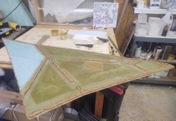
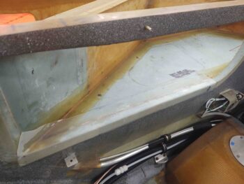
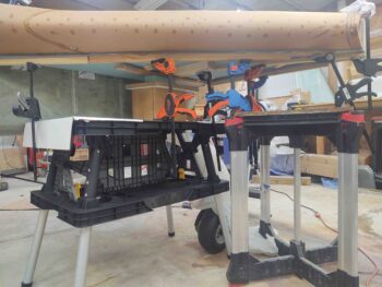
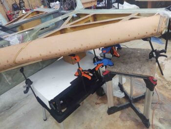
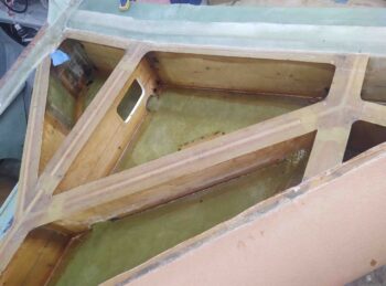
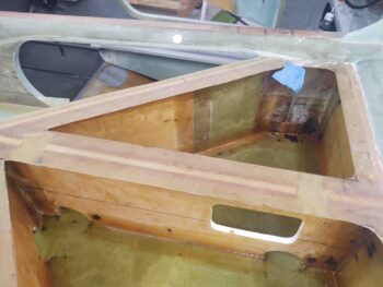
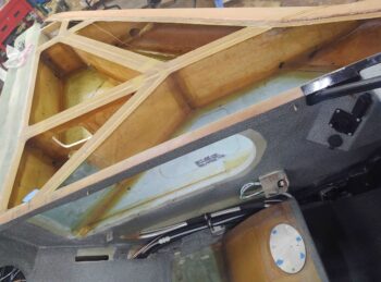
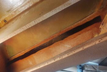
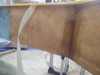
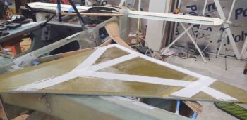
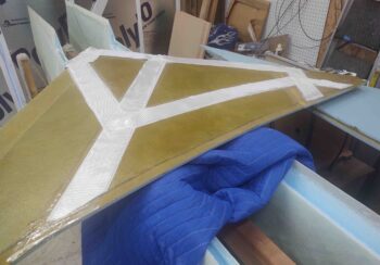
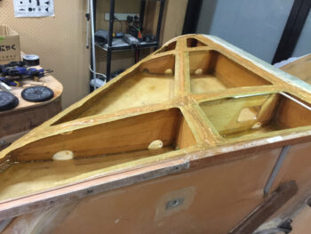
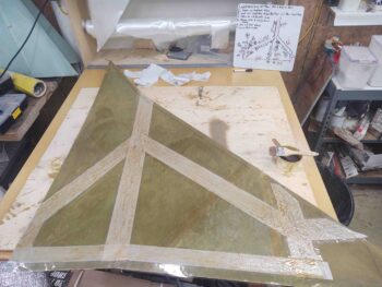
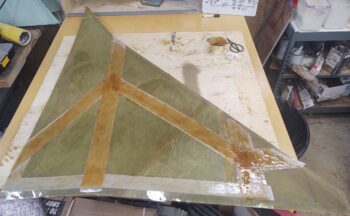
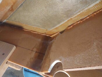
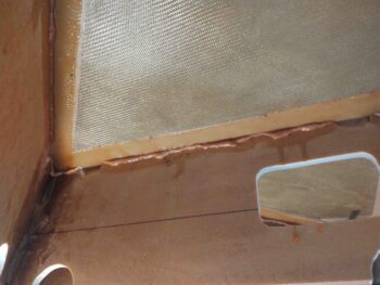
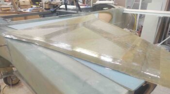
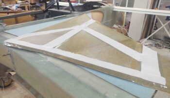
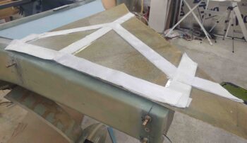
I started off today by sanding down all the glass edges of the left strake OD rib layup. I hate putting my hand into something on this plane only to have it extract a surprising blood sacrifice for doing so… thus I wanted to make this compartment hand friendly.

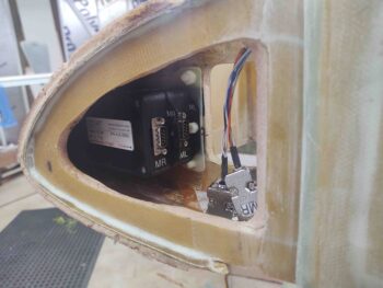
I also wanted to ensure the GRT magnetometers would fit unhindered, with no blockage or snags that may have been introduced by the new layup.

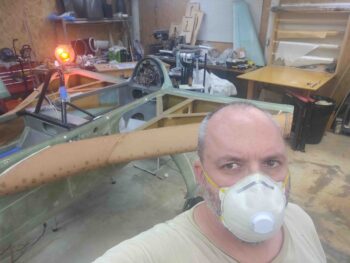
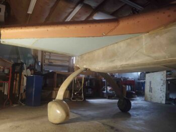
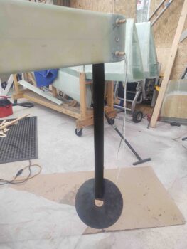
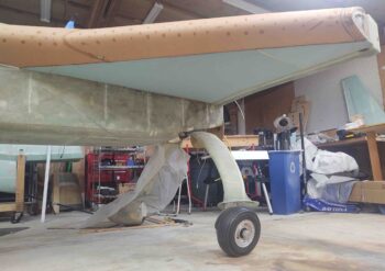
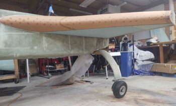
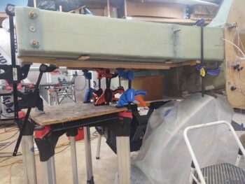
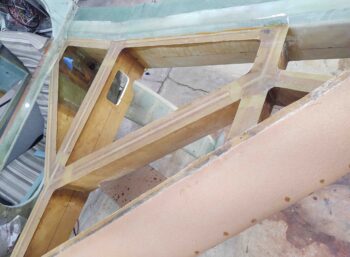
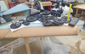
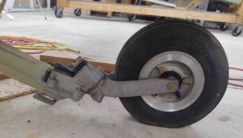
I then got to work on the strake fuel tank drains.  Before I get into discussing those, I wanted to show a quick shot of the approximate position my front landing gear will be in when I check the fuel for water contamination.  I didn’t want the plane to be in full grazing position, and actually wanted the resting foot about an inch off the ground.  Thus within seconds I can have it either in full graze, on the resting foot, or just a few inches higher for ingress into the plane or moving it.

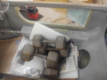
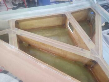
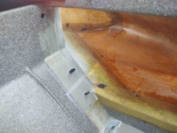
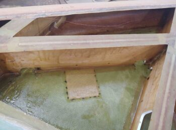
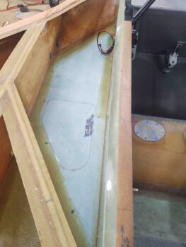
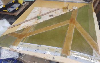
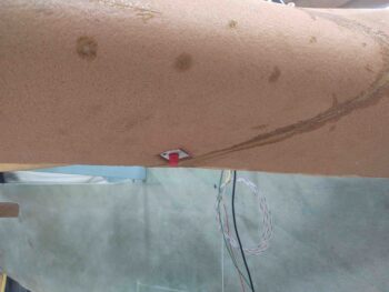
With the plane in the grazing position above, I then did the marble trick to test out the low spot of the strake which per plans designates the position of the fuel drain.  But then curiosity got the better of me and I subsequently poured some water in the leading edge to see what that might show me.

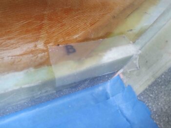
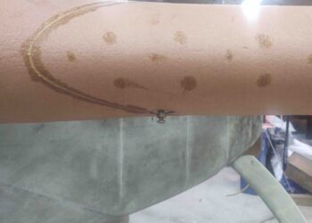
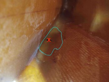
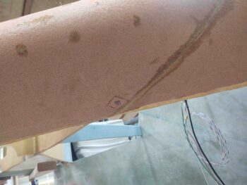
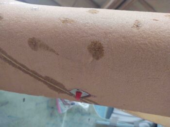
Interestingly, the water did tell me something.  Not so much on the right side, which confirmed that the marble –which I dropped in there multiple times– did come to rest in center mass of the small water puddle (black mark for marble, red X for water).  So I decided to place my fuel drain here.

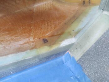
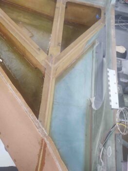
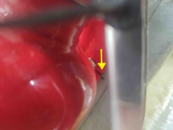
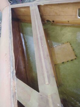
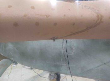
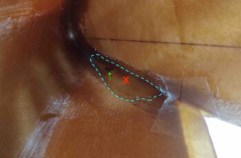
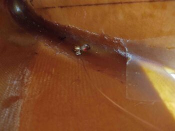
But the left side was a bit different. The spot where the marble came to rest consistently (black mark/green arrow) was towards the front of the water puddle, whereas my take on the center of mass (red X) for the puddle was a bit aft.  And more in line with what was going on over on the right side.

Thus, for more symmetry between right and left I decided to drill the hole on the left side strake at the puddle center mass a little over 1″ aft of the marble resting spot.  This puts both left and right fuel tank drains within a half inch of each other when measured from the center of the leading edge.

I took the first plunge, literally I guess, by drilling the drain hole in the right strake first.

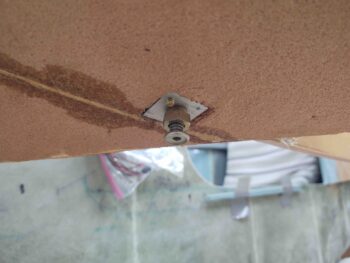
I then placed the fuel drain block up to the hole, sited down the hole from the inside to get the best centered alignment on the actual drain before marking the outline of the drain block on the external strake leading edge foam.

After cutting out the foam, I then test fit the drain in its aluminum block into the foam.

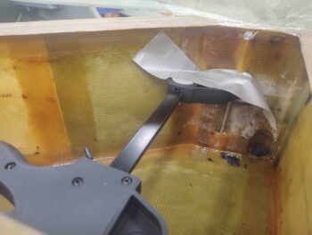
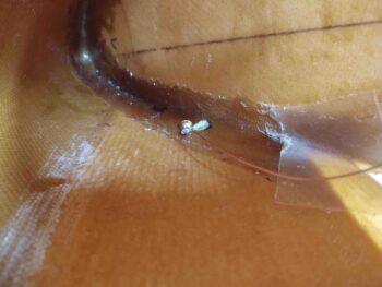
I carefully drilled up through the #8 tapped hole with a small diameter drill bit to then widen it out for the #8 screw.  I then secured the terminated internal fuel tank ground wire to the fuel drain block with the #8 brass screw.

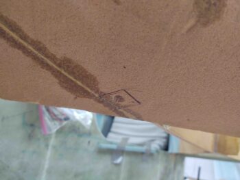
I then repeated the same process on the left side.  Here we have the fuel drain block marked and ready for cutout.

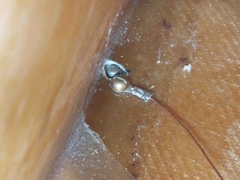
And the internal fuel tank ground wire attached to the fuel drain block via the #8 brass screw.

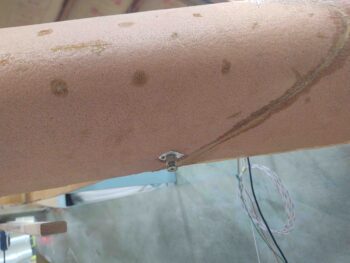
A shot from the outside.  Note that the brass screw is a bit long, so I marked it to be shortened.

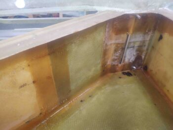
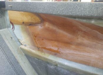
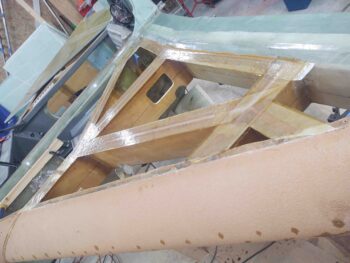
A bit later, after both brass screws had been shortened, I floxed in the strake fuel tank drain blocks into their respective leading edge notches.  Here we have the left side.

The thing I really like about this design and configuration is that the screw makes it easy to get the block into the cut foam notch nice and securely… no messing around with trying to apply pressure to keep the fuel drain block in place since the screw does all the work.

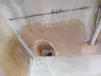
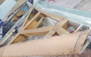
Here is the right side fuel drain block, floxed in place.  Obviously I removed the actual drain assemblies and put a protective red plug in place to protect the threads from flox.

In addition, a little while after I floxed in both side fuel drain blocks I performed a continuity test to ensure I was getting an electrical connection from the drain block to the ground wire. Both sides checked out good.

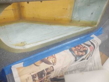
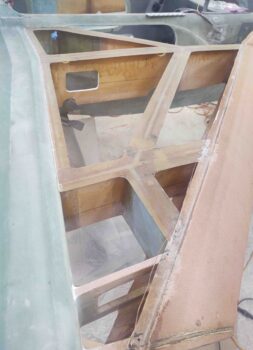
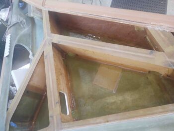
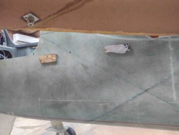
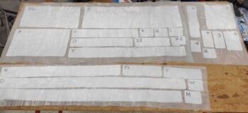
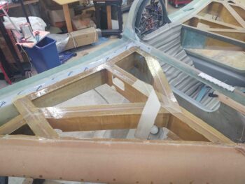
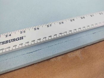
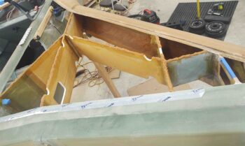
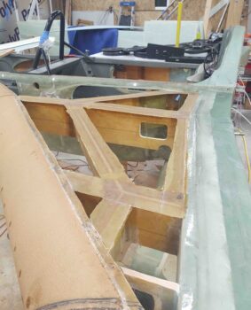
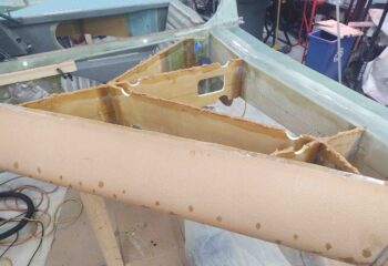
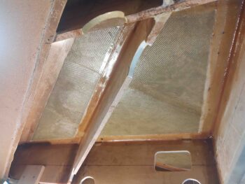
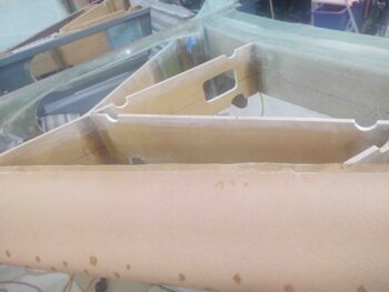
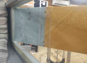
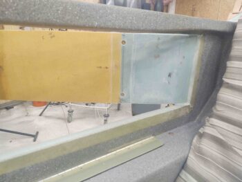
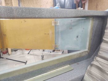
I left the floxed fuel drain blocks to cure while I then measured and drilled out 1/2″ holes into the baggage area side of the BAB baffle for the Atkinson fuel site gages.  Note that I didn’t drill all the way into the fuel tank side, leaving the tank side glass intact for better integrity and leak avoidance.

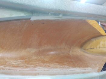
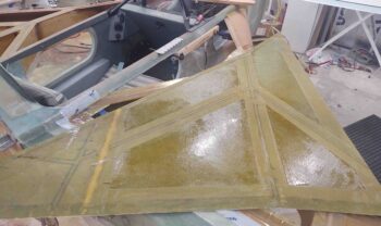
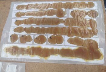
I then filled these future hard points with as wet as flox as I could without it running out all over the place. I then peel plied the floxed hard points.

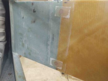
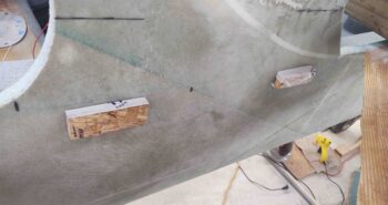
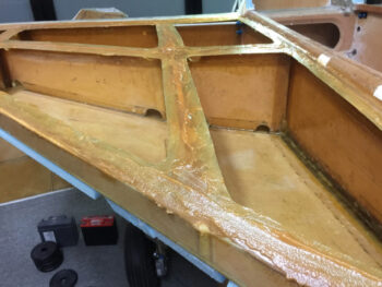
Here’s right side as well.  First the pockets drilled and cleaned out.

And then floxed and peel plied.

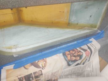
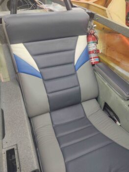
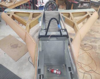
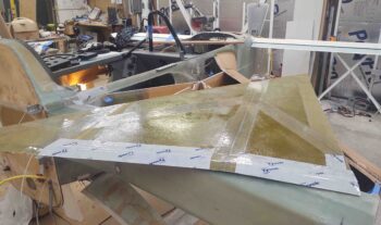
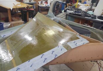
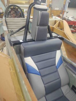
With the epoxy based tasks out of the way, I then cleaned, organized, and vacuumed out the front seat area to test fit the upholstered front seat cores.

I have to say, everything fit nicely and I’m very pleased with how the seat cores, both front and aft, came out.

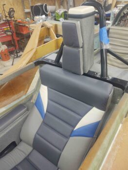
Here’s a shot of the forward lower seat pad.

And another headrest shot.  Note that the headrest pads are temp taped in place, so they are not aligned as they would be when permanently installed…. just as with the headrest pad I mocked up on the back seat.

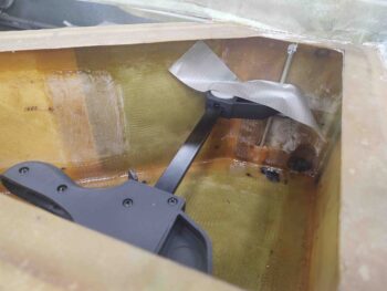
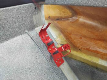
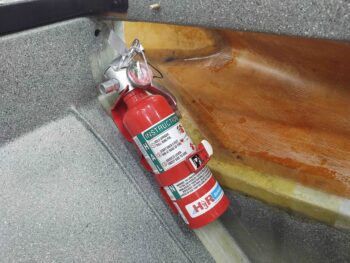
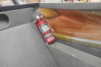
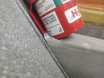
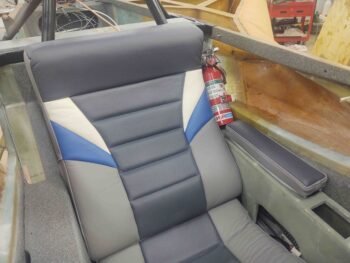
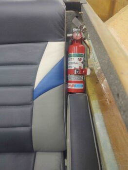
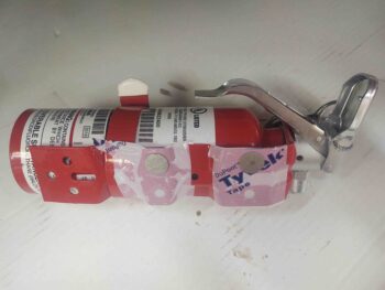
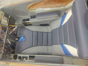
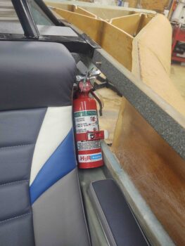
I of course wanted to check out the fit and look of the front seat cores, but another reason I wanted them in place was to see if my fire extinguisher was going to fit in the upper left corner, alongside of the seat, since this is where I decided the optimal location would be for it.

Thankfully it fit just fine.

Tomorrow I have a few more minor details to attend to, but then plan on getting the rib-top T-hats started.  At least on one side.