Chapter 13/19 – Left aileron weight

I started out today finishing up the task I began last night with marking the top front edge of the left aileron glass for trim.

Again, on my aileron cores… when I cut at the line designated in the plans to remove the aileron from the wing, it left a very slight glass overhang over the foam core.  You can see loose foam in the pic above at the edge that just peels right off when you touch it.

Obviously having a nice glass transition from foam to top aileron glass will not flow smoothly if this edge is left in place.  Again, this overhanging edge is under 0.1″ wide.

Outside I used my Dremel Tool to remove the edge down close to the marked line.  Then hand sanded it after that.  I taped 32 grit paper to the bottom of the level to make a longer straight temporary sanding board just for the ailerons, and used that here as well.

This top forward edge isn’t super visible here, but it is complete.

I then finished the prep on the left aileron by creating depressions in the foam for installing the aileron hinge plates (A2s and A5).  And digging out the foam for the aileron torque tube (A10).  With the aileron hardware ready to be micro’d and glassed in place, I was ready to attach the 7/16″ stainless steel rod that will serve as the aileron mass counter-balance weight.

First I had to finish trimming to length and cleaning up the end of the shorter piece of 7/16″ stainless steel rod that will mate end-to-end with the longer piece.  So I chucked up the rod piece in the lathe.

Not bad for a quick trim and cleanup job.

With SS rod lengths good to go, I cleaned them with some Simple Green first, to remove the major gunk.  Sanded them with 150 grit sandpaper. Then did a final clean with acetone.

I then whipped up some micro and slathered it onto the left aileron lower leading edge . . .

And set the 7/16″ stainless steel rod mass counter-balance weight in place.

Not surprisingly, I check out other builder’s sites to see what they did to pick up on any tricks and tips, and moreover to ensure I don’t miss anything critical.  I have to give a shout out to Dave Berenholtz and Ary Glantz for doing such a superb job in documenting their respective builds.

In particular, I gleaned this tidbit from Dave.  He actually hard-shelled his entire foam area on his ailerons to dial them in perfectly before glassing them.  I’m too lazy to go that far, but it did provide a solution to the ugly chasm that I was left with just behind the attached SS rod mass counter-balance weight on the right aileron.  I decide to work this now rather than when I was glassing the aileron front edge to ensure that I get an even surface.  As you know, larger areas of micro tend to get lumpy and deformed during layups and quite often don’t hold the shape or contour that we desire.

Thus, I filled the ugly area between the SS rod mass counter-balance weight and the foam surface of the right aileron’s lower leading edge with dry micro and then peel plied it.

Here’s a closer shot.

My final task of the evening was to glass 2-plies of BID onto the aft nose/avionics cover center flange AFT side, overlapping onto the two hinge tabs.  I then peel plied the edges and left this to cure overnight.

Again, I’m knocking out what I have determined to be prerequisite tasks before flipping the fuselage over to shape and glass the bottom strake skins.  Then I’ll knock out a bunch more as the plane is inverted for the last time (on the ground!).

Chapter 19/21 – Working Ailerons

I started off today by pulling the peel ply and cleaning up the 1-ply BID layup on the right strake pilot air vent structure aft wall.

Of course I couldn’t resist test-fitting the actual eyeball vent + mounting plate.  I’ve very pleased with the position and look of this setup.  Over the next few days I’ll dig out some of the foam in the vent entry hole and fill with micro and peel ply. I’m sure I’ll work the hole shape and design more, but I want to get the exposed foam cleaned up while I have access to the hole.  The last step will be to fill in the interior side of the vent structure wall to finalize the vent construction.  I guess actually the very final step, along with the rest of the cockpit, will be the final paint.

I then got to work on the right aileron mass counter-balance leading edge.  CP #26 notes that the bottom of the aileron leading edge at this weight/rod needs to be round, without any sharp edge, to prevent any “early airflow separation on the up-deflected aileron” which will reduce roll power.

Using my handy Dremel Tool I then removed the sharp edge of the glass to produce the nice rounded edge required by CP #26.  Yes, a bit blurry but you can see what I’m on about.

Then came yet another round of humbling for sins of the past.  As I’ve explained before, I reordered my build in Germany to maximize use of a massive amount of MGS I was able to purchase there in bulk for a significant cost savings.  Since I couldn’t ship it back to the states I needed to use as much possible as soon as possible.  This meant building the wings fairly early on in the build.  Not a huge deal, but clearly we are better builders towards the end of the build and the wings are the biggest part of this build.  Oh, what I would have done differently building them now vs then.

I was given some advice by one of the old guard builders to save time by slathering up the surfaces of the build with micro as soon as the glass was in the “green state” (not fully cured) and this would eliminate the need for prepping the glass surface.  I decided to try that out on the bottom of the right wing… between my inexperience and this just not being a great idea, I regretted it ever since.  No huge deal, but in the area of working the aileron, it definitely had a slight impact.

Fast forward years later, and I now have to remove a 1″ strip of that micro on the bottom leading edge for the upcoming 1-ply BID layup that will finish off the primary skin of the aileron…. each end will still need to be glassed as well, of course.  All in all it took about 10 minutes and wasn’t a big deal.

I was then ready to glass the right aileron, but I had another slight issue: not enough BID! To be clear: not enough BID to layup one ply with NO overlapping seams.

Not too long ago I placed an order for 5 yards and thought that would be plenty for the rest of the build… yeah, right!  The myriad of BID tapes alone required for the strake build really ate into that stock of BID.  I did place an order for another 10 yards a few days ago, but with 2 weekends involved in that timeline and it being shipped from ACS’s California store, it will still be a another few days before it gets here.

Thus I went to work on the left aileron.  Just like the right side I trimmed back 7/16″ of foam from the bottom leading edge to allow mounting of the 7/16″ stainless steel rod mass counter-balance weight.  I then marked half of the exposed glass and trimmed it off.

With the bottom leading edge prepped, and almost another hour of peel ply removal ensuing… I then marked the left aileron top leading edge for trimming.  Again, this is just like the right side where my aileron top glass overhangs the foam core just shy of 0.1″.  Of course this narrows the width of the top of my aileron by a hair, but I’d rather have that then to have to add in a bunch of micro and deal with a much more difficult and less elegant layup as I’d be fighting that edge the whole time.

It was late and dark, and I like to trim and sand as much as I can outdoors.  And quite frankly after fighting old, dead peel ply for an hour I was ready to take a break.  So I called it for the night.

Chapter 13/19/21 – Right aileron weight

Today I started off by cleaning up the intersecting junction between the right strake leading edge pilot air vent aft wall and the interior leading edge surface.  I then added some micro to fill in the gaps and laid up a ply of BID.  I then peel plied the BID.

I then got to work on the aft nose/avionics cover hinge securing hardware.  It was time to implement the final solution here and with my front flange ready to be glassed into place, I was ready to finalize the hinge mounting.

Since the flange will cross between the 2 hinge tabs, I first needed to move the front bolt one position aft to create space for the front flange and overlapping glass.  This will be more obvious below and in the ensuing blog posts.

I started by drilling out the second hole from the front for the front screw mounting position. Then, with 3 holes equally spaced on each side, I drilled out the middle hole. Below you can see that I started mounting the final hardware.

If you’ve read this blog for any given amount of time, then you’ll know I’m not a fan of button head screws.  Thus, I have a lot of them on hand from the original hardware purchase for the plane build.  But to be fair, there are places that they do actually serve a good purpose.  Here is one such area.  Sorry for my camera’s inability to focus things nicely sometimes, but you get the picture.

I then cut out the center flange from 1/16″ G10 phenolic and clamped it into place on the nose-side tabs.  This flange will serve 2 purposes:
1) It will allow me to secure the aft nose cover with CAMLOCs from the nose side into this aft nose cover flange, and
2) it will compress a “B” seal to better prevent water/moisture from entering the plane via the front nose intersection.

If you look closely you’ll see a bit of clear tape around the flange piece… this is to protect the nose and hinges from the 5-minute glue that I then slathered onto the edges of the flange, top and sides, where it intersected/mated with the aft nose/avionics cover interior edge.

Which I then closed and added just a bit of weight to close up any gaps between the cover and the flange that might exist.

Here’s a shot from inside the front nose hatch looking aft.  With the flange tightly clamped to the nose tabs, with their 1/8″ phenolic pieces added on the aft side, it should create a 1/8″ gap between the flange and the top aft edge of the nose bridge.  This is where the “B” seal will be positioned.

About an hour later I pulled off the weight and opened it up.  Not bad.  Although there was a slight offset, or cant, from side to side.  As in one side of the flange further forward than the other.

Just by looking you can’t see this angle, but after multiple tests of positioning the aft nose cover + flange back into place, it fit snugly to the nose tabs.  Guess my lopsided, slanted build will have to do . . . no changing it now without major rework and that is not happening since none of this will prevent the airplane from actually flying!

Here’s another view, closer to where the flange will be positioned when the aft nose cover is actually closed.

I then floxed and glassed the front side of the flange with a ply of BID.

I then got to work on my ailerons.  I have to say I’m not overly pleased with my right aileron cutout job.  Despite my best efforts to follow the plans specifically, my bottom cut line was off almost a 1/4″.  This of course won’t work since when the aileron must travel upwards it binds on the top inboard edge of the wing aileron notch.

Moreover, I had to figure out and ensure good aileron travel before I micro’d the aileron’s steel bar weight in place. BTW, I’m using 7/16″ diameter stainless steel vs the 3/8″ plain steel called out for in the plans.

Go ugly early.

Bottom line is that protruding lower inboard aileron edge was lopped off much closer in line vertically with the top inboard aileron edge.  I’ll clean up the resulting gap on the bottom side of the wing aileron notch with a few plies of glass and a slathering of micro.

Once the right wing’s aileron and its mating wing notch were both sanded and shaped to allow good aileron travel, it allowed me to determine the proper length of the stainless steel aileron weight.  The last thing I want to do is secure this steel bar into place and then have to cut on it to trim it, thus creating a ton of heat with it being attached to foam and glass.

Before I micro’d the steel bar into place though, I went ahead and prepped all the other components that get added to the aileron before it all gets secured via 1 ply of BID: A5 hinge plate, 2x A2 hinge plates, and the A10 aileron torque tube.  In addition, my aileron core top glass edge overhung the foam core by a hair (0.070-0.080″) that I needed to shave off for the glass to have a good transition from foam to top aileron skin overlap.

Of course I had to trim 7/16″ worth of foam off the bottom leading edge of the aileron for the weight.  From there, I trimmed about half of the exposed glass edge to provide just enough of a lip for the stainless steel bar to rest on as it was secured to this front edge. And let’s not forget the almost hour it took just to remove the old embedded peel ply as well (can’t wait to NEVER have to remove any old dead peel ply again!).

Finally, I was then able to micro in the 2 lengths of 7/16″ diameter stainless steel bar to the front edge of the right aileron… which I left to cure overnight.

Tomorrow I’ll continue to work the ailerons, the aft nose/avionics cover and some on the right pilot air vent to get these completed before flipping the bird over to shape and glass the strake bottom skins.

Chapter 19/21 – Left aileron sheer web

I started out today with a couple quick round of layups.  First I 5-minute glued the right strake pilot air vent structure aft wall in place and then glassed it on the front side with a ply of BID. I did use a bit of micro as a fillet.  Yes, it looks a bit of a mess with having to go around the upper and lower nutplates, but I think it will hold fine combined with the aft side BID securing it as well.

Here’s a shot of the aft side which I’ll shape and glass tomorrow.

I also laid up a ply of BID on the right wing aileron hinge hard points to protect the aluminum hinges from the carbon fiber, as well as adding a bit more meat for the 82º SS CS screws to bite into.  I then peel plied these 3 BID strips.

A while later I pulled the peel ply.  In fact, after I snapped this pic I razor cut the top edge of the glass to clean it up.

This afternoon I was finally able to get the left wing aileron trough sheer web glassed.

I did lay up the glass pretty much how I did on the right wing, except for this time I went ahead and added the final strip of BID on top of the carbon fiber at each aileron hinge hardpoint.

Here’s the inboard aileron trough sheer web . . .

And the outboard sheer web.

A final shot showing that both wings’ aileron trough sheer webs are glassed and complete.

Over the next few days I’ll be working on the right strake pilot air vent structure, the aft nose/avionics cover install, and the wing ailerons themselves.  I want to get all these done, plus just a few more items off the list, before I flip the fuselage to glass the bottom external strake skins.


Chapter 13/19/21 – Strake Vent

As with a lot of my posts lately this covers the last couple of days.

After an overnight cure on the sheer web in the right wing aileron trough, I trimmed the glass along the edges and did a bit of sanding to knock down any roughness. I’ll fine tune the edges before I cut out the 0.2″ notches along the top edge for the aileron hinges.

After a text back and forth with Marco I realized I had probably not made myself overly clear regarding the carbon fiber reinforcement plies.  I laid up the original 1-ply BID strip for the hinge reinforcement –as per plans– before I added the carbon fiber.

However, to ensure no negative galvanic-type reaction between the aluminum hinges and the carbon fiber, I will be adding at least 1 more somewhat sacrificial ply of BID on the surface of the carbon fiber.  Moreover, I peel plied the carbon fiber since I plan on installing the Melvill-style stainless steel CS hex drive screws to secure the aileron hinges to the wing. These screws have 82º heads vs the aircraft grade 100º heads, so they go a tad bit deeper into the material.  Once I assess how much thickness I should add to allow for the Melvill style screws, I’ll add anywhere from what I presume will be 1-3 plies of BID onto the face of the carbon fiber… thus, the peel ply.

One more shot of the trimmed and cleaned up aileron trough sheer web layup on the right wing.

I then took a short bit of time to carefully drill out the aft nose/avionics cover forward CAMLOC securing tabs.

I then got busy on the front seat right strake pilot air vent.  I made an outline (black line) of my G10 phenolic aft wall of what will be the vent housing at the very front of the right strake.  Here I’m using 0.040″ thick 2024 aluminum to make a removable mounting plate for the eyeball vent.

I then drilled the mounting hole for the eyeball vent in the aluminum to match the same mounting hole in the G10 phenolic plate.  Lastly, I marked an inset cut line (green) about 3/16″ inboard of the G10 phenolic plate perimeter.

After drilling the 3 mounting holes, which here serve more like alignment holes, I then cut out the aluminum eyeball vent mounting plate along the inset green line.

I then mounted it all together to check fit.

And drilled out the holes for the 3 x 8-32 mounting screws.

I then riveted in #8 nutplates for the 3 mounting screws.  Note that at this point I have widened the diameter of the hole in the phenolic plate so that the eyeball vent housing clears the phenolic plate when mounted.

Here we have a front shot of the 3 x #8 mounting screw nutplates.

Again, the light green phenolic plate with the nutplates will become part of the aircraft structure as the aft wall of the right strake vent housing. The eyeball vent itself will be attached to the removable 0.040″ thick aluminum plate that is mounted via 3 x 8-32 screws to the vent housing.

Here’s the assemblies mounted together, from the back side.

And mounted together and test fitted in the strake.

More of a side view . . .

Here we have the strake as it looked pre-vent hole . . .

And after I used a 5/8″ hole saw to drill out the vent opening.  I’ll of course do a bunch more shaping and contouring to make it look nicer and soften/round all the edges.

It was hard to grab this pic, but essentially this strake hole is very close to dead on in line with the aft intake area of the eyeball vent.

One last shot for now of the eyeball vent assembly set in place with the initial strake vent hole drilled.

My last build task for the day was spending well over 2 hours very slowly (not by choice) and carefully removing all the embedded peel ply from the top edge of the aileron trough on the left wing.  This is painstaking work and is a reminder of the hours spent on removing the peel ply from the wing trailing edges!

The worst part of this, after getting the top edge done, is now I have to do the same thing on the bottom edge.  Truly: Ugh!

Tomorrow my goal is to get the right wing aileron trough prepped, cleaned up and glassed.

Chapter 13/19 – Right aileron sheer web

Although there’s not a ton of pics, I did spend a almost all day in the shop working on the following.

First off I cut 1/8″ phenolic spacers that match the original tabs on my nose “bridge” piece just forward of the canard.  These spacers will allow me to install a “B” seal across the entire nose bridge piece and compress it at the correct pressure to greatly reduce any water and/or moisture finding its way in.

I then sanded the forward (mating) side of the two middle aft nose/avionics cover spacers. The 2 outer spacers have not been sanded yet here.

I then floxed and riveted the spacers into place on the original nose “bridge” tabs.  Again, these spacers are merely to provide a 1/8″ standoff for the “B” seal that will be situated above them.  I will create a mirrored flange on the aft nose/avionics cover that match these tabs, so that when large holes are drilled all the way through the tabs it will provide 4 CAMLOC securing points.  The CAMLOC studs will come from the front, nose hatch side, towards the aft canard side with the receptacles attached to the flange tabs on the aft nose/avionics cover.

I left the flox on the newly installed tab spacers cure as I then got back to work on the right wing (left in pic below).  I first spent a good half hour with the Dremel tool removing all the peel ply from the bottom inside edge.

I’d like to give props to my ex-girlfriend Gina here… she was a phenomenal help in the initial stages of this build.  She was was a great epoxy/flox/micro mixer and cut a lot of glass for me.  Well, tonight I actually am using glass for the wing aileron sheer web layups that she cut and prepregged back in 2012.  So even almost 9 years later this is a big help!

I ran out to dinner immediately following this multi-hour layup… so here is round 1 of the pics of the right wing aileron trough sheer web layup.

And then round 2 after I spent a good 20 minutes scraping all the excess wet epoxy off of the glass and that had collected in the bottom of the trough.  As you can see, I opted for a common mod of adding in a ply of carbon fiber BID at the hinge points to add a bit of rigidity for the hinges.  I’ll note that these carbon fiber patches are both the last ply on so as not to interfere with interweave strength of the BID.  And, moreover, they are separate plies of carbon fiber so the rigidity is localized to each hinge, and does not carry out for the entire sheer web or wing.

Tomorrow I plan on working more on the aft nose/avionics cover and also the left wing aileron sheer web.

Chapter 19/21 – Fuel tank grounding

Today I knocked out the final tasks on the fuel tank grounding wires.  I started by grabbing a couple of ring terminals and modifying them by snipping off the actual ring portion.

I then slid just the leftover clamp part of the ring terminal onto the pair of ground wire leads in the left fuel tank….

Here’s a closer shot.

I then crimped the 2 ground wire leads together, removed the blue plastic coating on the modified terminal, and snipped the shortest of the 2 leads.

I then coiled up the fuel tank ground wire and set it in position so that when I mount the top skin and eventually cut the hole for the fuel tank filler cap, the ground wire will be right there ready to be connected to.

I then repeated the process for the right fuel tank.

I then spent a bit more time dialing in the aft plate for the right strake root pilot air vent. After getting the shape and position determined, I cut the plate out of 1/16″ thick G10.

From my test fit below I think this air vent configuration looks really promising and I’m excited to see it all come together.

My next task was to finally layup the inside glass BID on the very front of the right strake opening.  I didn’t overlap the glass onto the inside sidewall face on the very front sharp curve, and opted for a flox corner/edge on the inboard edge instead.

In addition, I laid up a ply of BID to the remaining top edge that had about 7″ left to do after my previous layup.

After my two layups on the front right interior strake opening, I peel plied certain areas of these layups.

A few hours later, after pulling the peel ply and a quick cleanup, this is what it looked like.

I also spent quite a bit of time today on the right wing aileron trough.  About 2 hours all told.  This shot is after I put the wings back in the shop from outside.

I was able to get the initial foam dug out from the inboard edge . . .

And all the peel ply removed from the top edge.

I got a good bit of foam removed and edges cleaned up on the outboard edge as well.

But still have to remove the very stubborn peel ply from the bottom edge.  I suspect I’ll be spending at least another hour to get this task completed, at which point I’ll do a final prep and then layup the 3-ply + aileron trough sheer web on the right wing.

Then I’ll get to work on the left wing as I also knock out the right strake pilot vent and the final installation of the aft nose/avionics cover.


Chapter 19/21 – Strakes, wings, et al.

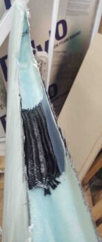
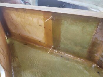
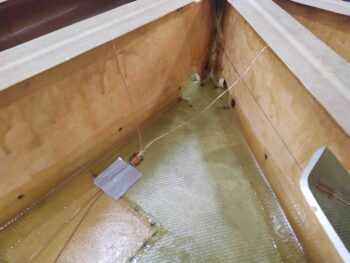
Today I started out on the second round of securing the fuel tanks’ ground wires to create an up and down roller-coaster style pattern so that the ground wire breaks the surface of the fuel to better remove pesky electrons loitering thereabouts.

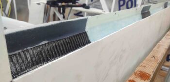
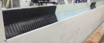
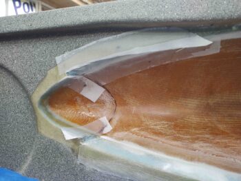
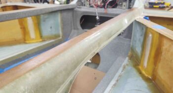
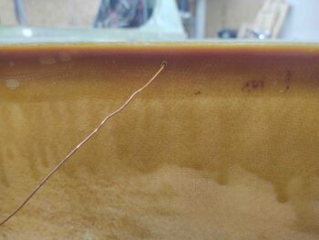
I started on the left side and tacked the ground wire to the underside of the strake leading edge with a dab of flox and small patch of BID.

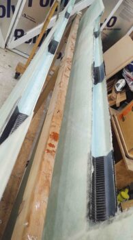
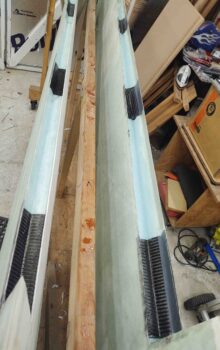
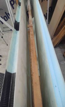
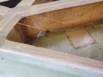
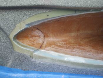
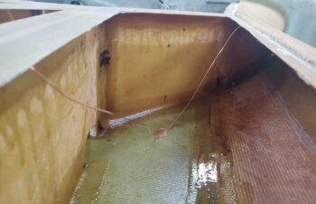
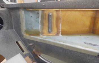
In addition, I decided to run another ground wire lead to the aft inboard corner.  I figured fuel in these birds obviously follows the slope of the CS spar to drain back in this aft corner, so if I have only very little fuel in the tanks before refueling I still want it grounded.
[I understand that these birds almost always get refueled in some variant of the grazing position…. but in the off chance I go from very little fuel to refueling to full tanks for say, a long cross country trip, I want every scenario covered. It’s just too easy to do at this point not to fairly quickly add in another ground lead].

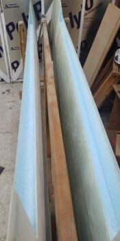
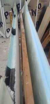
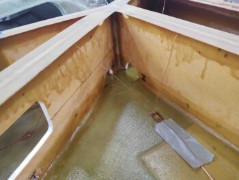
I then did the same on the right side, tacking the ground lead to the underside of the strake leading edge.

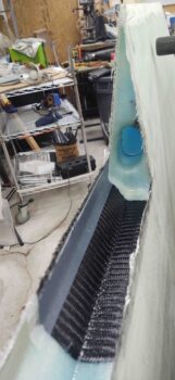
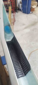
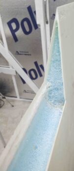
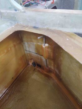
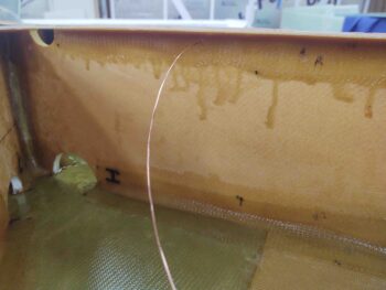
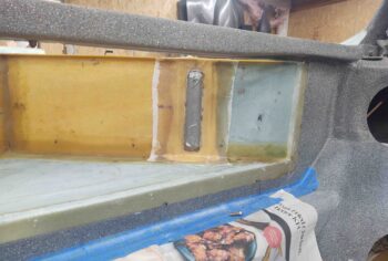
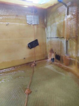
And then running ground lead #2 to the aft corner.  As with the left side, this lead runs along the bottom of the tank and then turns vertical in the very aft corner up to the bottom of the top tank lip.

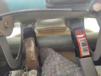
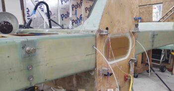
I had a somewhat surprising issue during the strake build when it came time to remove the wings –after my wing bolt mod where I had captured all the wing bolts inside the CS spar and had the bolts sticking out… all facing aft. Let’s just say that the ensuing effort to get the wings off with this mod in place, was, well, challenging to say the least.

With all 3 bolts sticking straight aft, the amount of wiggling and rocking to get those wings off was not overly comforting.  There was a bit of manipulation to get the wings ON, but nothing compared to removing them.  Especially with the thought of the strakes being completed and here the wings have to be fought with to be removed: fool me once shame on you, fool me twice shame on me . . .  Right?

I had made a decision immediately following the first not-stellar experience of version 1 of the wing bolt mod to reverse the inboard bolts so that only the outboard 2 bolts were protruding aft.  This eliminated the 2′ or so arm that clearly impacted the alignment of these bolts if they were not all exactly parallel with each other.  With just the slightest angular offset, at that big of an arm —in my thinking at least— it was creating the friction that jammed up getting the wings off without hassle and malcontent.

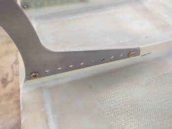
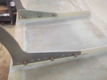
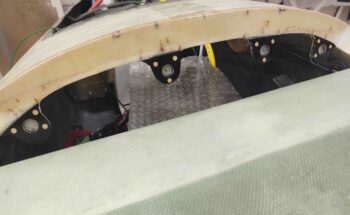
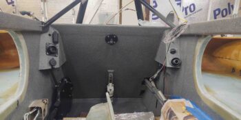
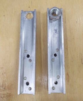
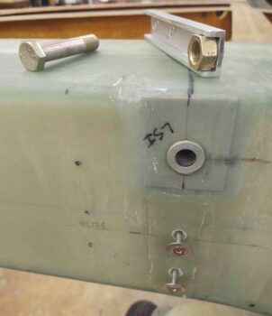
My first task was removing the inboard wing bolts and then remounting the securing bracket on the inside of the CS spar.  Here’s the left side.

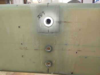
And the right side.  I then marked the center point of inboard wing bolt hole on the bracket using a 1/2″ drill bit… very carefully.

One issue was how to secure the nut to the bracket. Securing a bolt is easy since it goes through the hole and that captures it in the up/down position.  The bracket then secures it in the left/right and forward/aft positions.

Well, in a somewhat odd and rare experience on this build, I discovered that capturing the nut was actually going to be very simple. Since it has a hex portion and then a significantly smaller round portion on the part furthest from the bolt head. So I drilled out top of each bracket to allow for this round part to be press-fitted into the bracket.

And voila!  Once the bracket was secured in place the nut would be captured so as not to slide out of position.

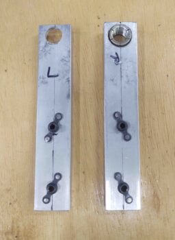
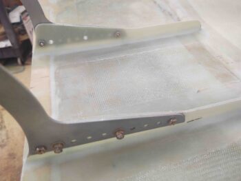
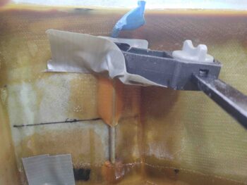
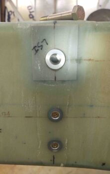
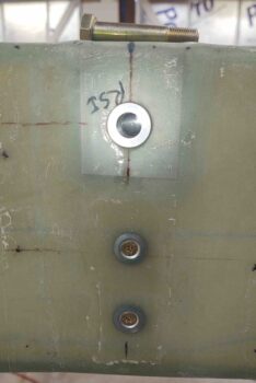
Here’s a few shots of the press-fitted inboard wing nut into the bracket.

Again, the hex portion is captured by the edges of the bracket, in the “U” channel.

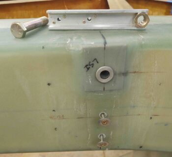
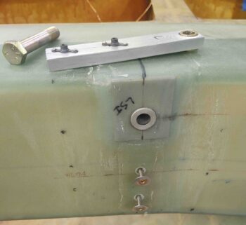
My method for dialing in the position for the actual bolt getting mounted in repeated fashion into the nut was to mount the nut in the CS spar contained by the bracket, but not tighten it fully.  I then threaded the bolt in place and as I progressively tightened the bolt, I progressively secured the bracket screws until fully tightened.  By the end of this process I could remove the inboard wing bolt and replace it, tighten and remove again with the nut positioned in the exact spot it needed to be to engage trouble-free with the bolt.

This mod of a mod allows me to reclaim the more traditional method of mounting and removing the wings by sliding the wings onto the outboard bolts, and then aligning and securing the inboard bolt.  All still without having to climb under the wing or get inside the plane —rather person #2 inside the plane— with arm up inside the CS spar.

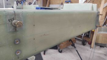
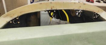
Here’s a final shot of the nut captured inside the CS spar, aligned and ready to receive the inboard wing bolt.

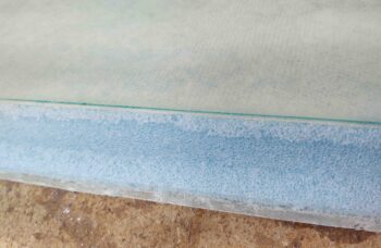
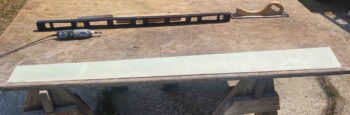
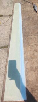
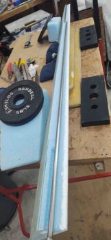
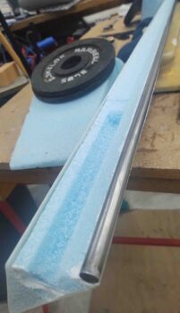
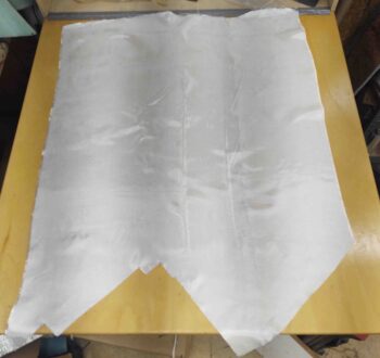
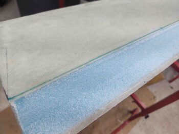
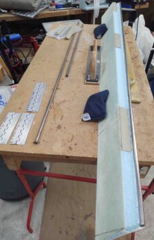
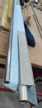
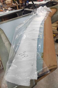
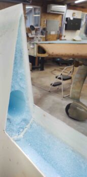
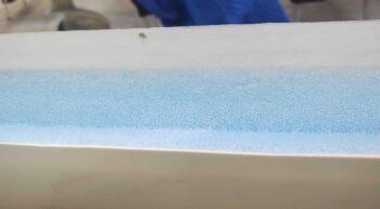
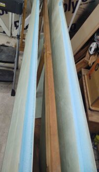
Before it got dark I decided to kick off the first real effort of removing the excess foam inside the wings’ aileron channels.  I pulled the wing dolly outside and started cutting and hacking away at the wing aileron channels.  This is to remove the foam that is there when the wing cores are hot wired, and provides support during wing glassing, but then needs to be removed prior to glassing in the aileron channel sheer web.

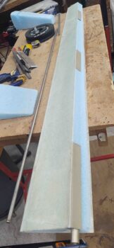
I then brought the wings back into the shop, vacuumed out the blue foam bits and dust and then did another couple of rounds of cleaning up the channel.  I’ll refine it more over the next couple of days and get it prepped for the 3 plies of sheer web BID that goes in.

One specific task that won’t be fun and will most likely take a bit of time is removing the peel ply that I ran under the foam that was just removed, along the top and bottom edges of the wing aileron trough.

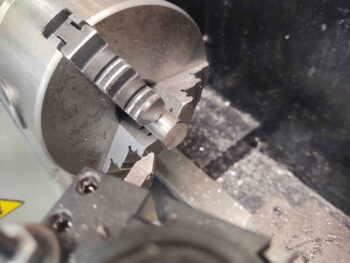
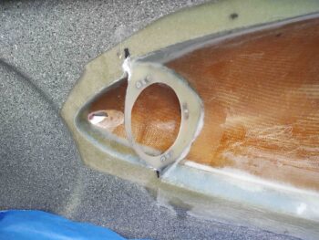
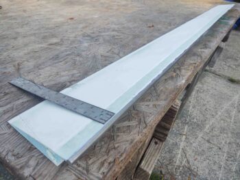
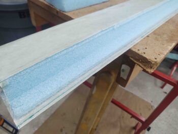
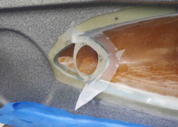
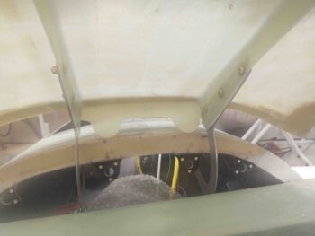
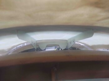
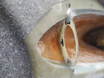
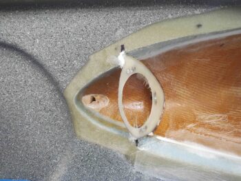
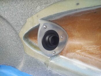
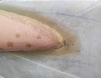
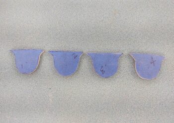
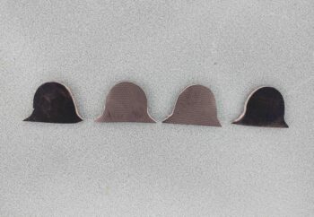
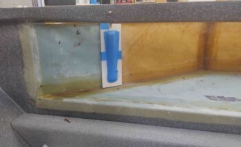
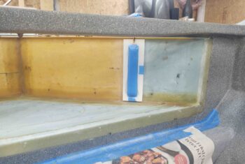
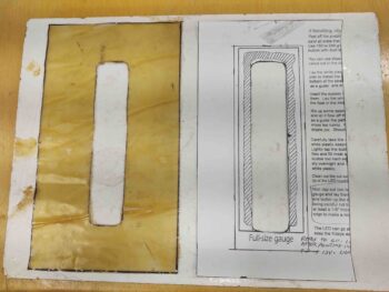
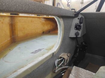
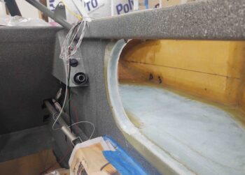
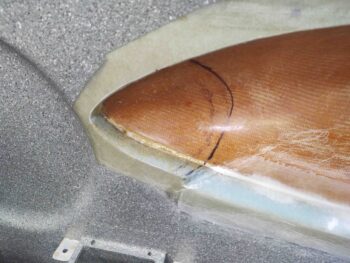
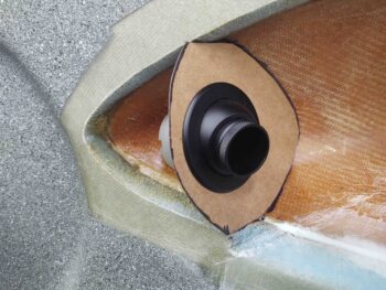
It was getting a little later in the evening, so I decided to play around a bit with the right strake root pilot air vent that I’ll create/glass/install. It took a number of machinations to figure out the angle, size, fit, configuration, etc. for the vent.

I’ve been mulling this vent around in my mind for over a month now, even before Marco and Chris came down here a few weeks ago. I say this because what I’m doing with these separate (not connected to the RAM pressurized heating/air duct system) strake vents for both pilot and GIB are heavily influenced by what Mike Toomey did on the Long-EZ that he built and Chris eventually bought.

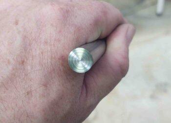
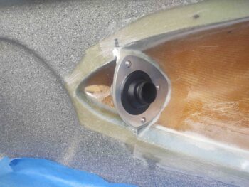
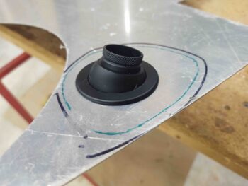
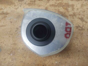
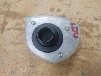
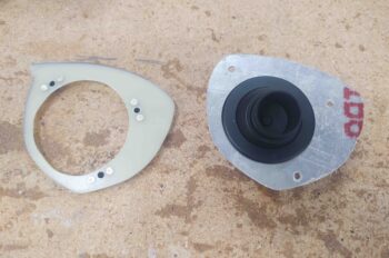
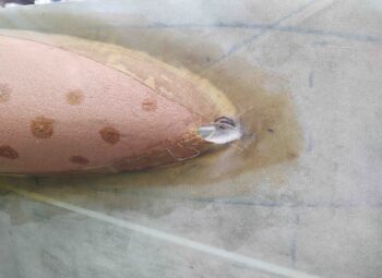
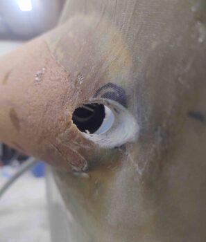
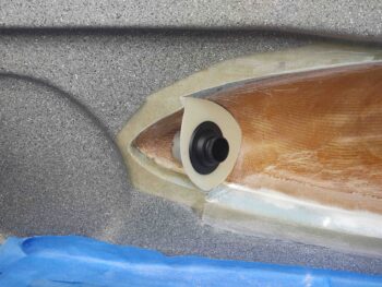
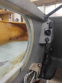
Within the past week I decided to go with the same type of eyeball vent that I’m using on my panel, the Aveo.  In fact, I’m not just using the same type, I’m actually using the exact one since I’m stealing the black one off the panel and will replace it with a silver/aluminum colored one for contrast with the black panel.

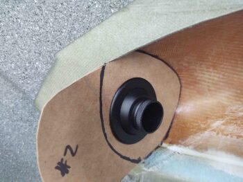
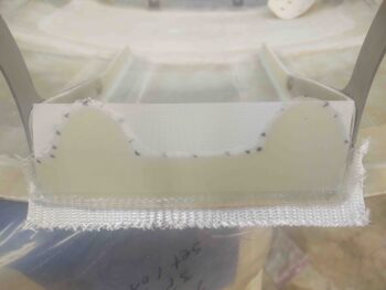
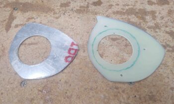
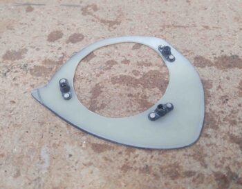
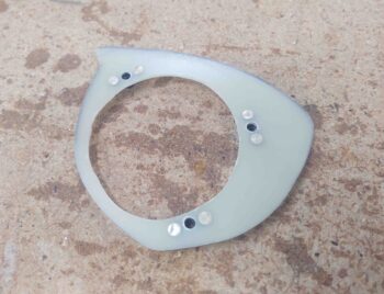
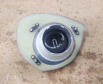
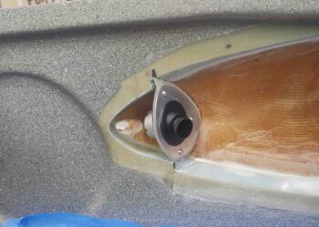
This type clearly does not have the flange and 4 corner screws as some other common types do… this is where my design is slightly different than Mike’s.  However, for maintenance, and to allow for some type of filter screen replacement and cleaning, I will be mounting this onto a plate that will subsequently be secured to the vent structure via 3 screws.

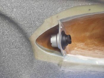
Notice that due to the angle of the strake and required position of the vent that it will protrude out slightly from the sidewall, with a noticeable but non-intrusive bump.

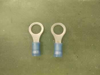
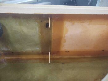
It was fairly late in the evening at this point, so I stopped with my initial rounds on the wings and pilot air vent and got one last round of fuel tank ground wire securing under my belt.  Actually this is the last round since all that needs to be done once this flox and glass cures is to terminate the 2 ground leads together and lop off the shortest of the 2 leads.

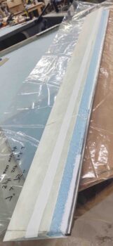
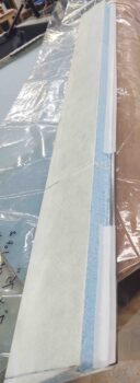
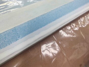
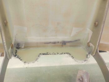
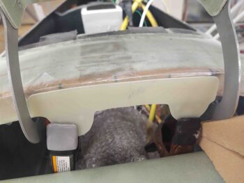
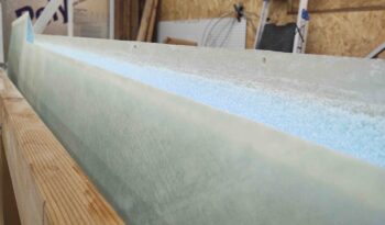
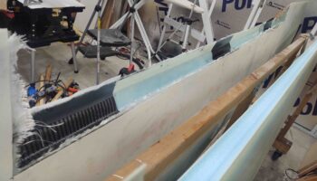
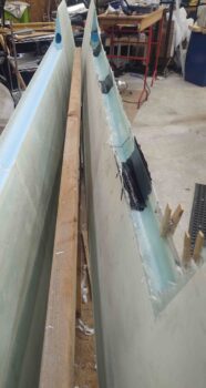
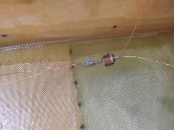
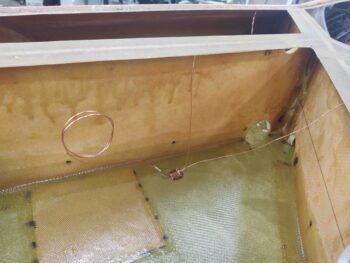
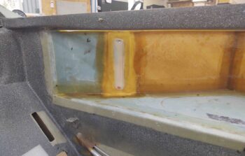
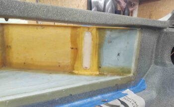
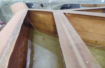
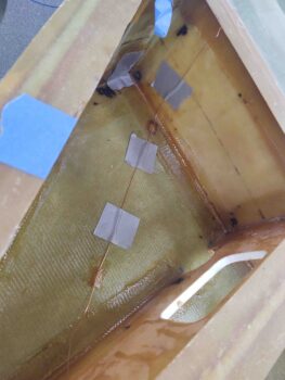
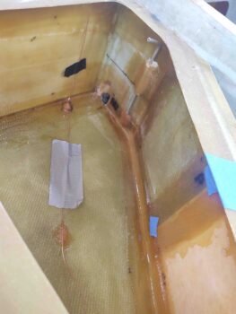
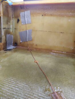
I started again on the left side.  I ran the forward and aft ground wire leads together and floxed/glassed secured them to the tank floor, just off to the inboard side of where the tank fuel cap will be located.

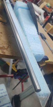
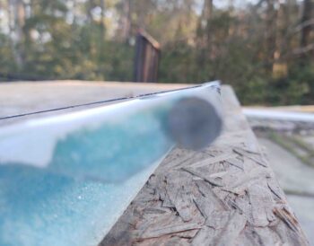
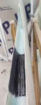
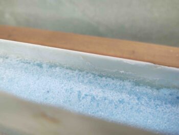
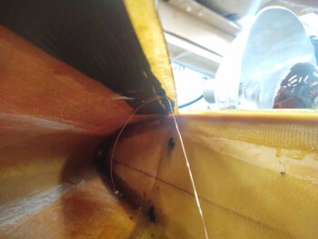
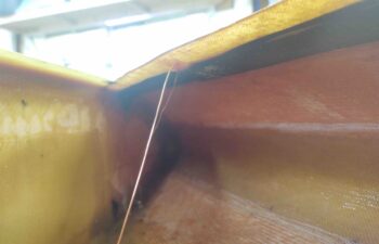
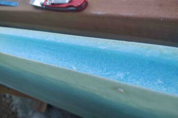
In the left aft tank corner I secured the end and top of the ground wire to the top corner edge of the tank, again using a dollop of flox and small patch of BID.  I also secured the middle of the wire on the tank floor to eliminate any type of vibration action going on.

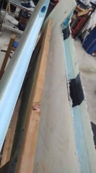
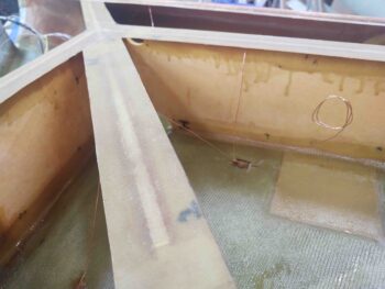
I then did the same thing in the right tank.  First with combining and securing the 2 ground leads together.

And then securing the aft corner ground wire lead.

With my myriad of disparate tasks done for the day, I called it a night.

Chapter 21 – 5 Layups

The 5 layups I refer to in this blog title are the ones I did yesterday: Left and right fuel site gages, left and right fuselage side edge of the GIB front strake opening, and the right tank sump vent securement.

Today I didn’t get a lot done but I did finalize those 5 layups by pulling peel ply, trimming glass and cleaning them up.

I started with the fuel site gages.  Thankfully the glass was still in the “green” stage and was still fairly soft and pliable.  I don’t like putting protective tape on something, then laying up glass without then immediately removing the tape before final cure to ensure everything is ok.  This was a notable mistake I made a time or two regarding the canopy.

On the fuel site gage I spent a good half hour on each one with a razor blade very carefully trimming glass away from the site glass and removing slivers of tape that got underneath the glass edge.  The end result of my fuel site glass installation, including this effort, I would say is a solid “good.”  Not stellar, but definitely acceptable.  Of course once this area is painted and the site gages are marked, functional and fuel levels able to be ascertained, all this will fall into the forgettable past.

Albeit slightly out of focus, here’s a shot of both fuel site gages installed.

Here we have the right thigh support sump tank vent secured to the main tank sidewall.

And a shot of the GIB strake openings front curved sidewall edges glassed, peel ply pulled, trimmed and sanded.  These turned out just fine as well.

I did some planning and assessing on my fuel tank vents.  Since those will get routed outside of the cockpit and up through the top engine cowling “shoulders” that extend forward and slope down on each side of the turtledeck, I’m going to wait until I’m ready to close out the tank with the top skins before I install those…. to ensure no damage occurs during the fuselage flip.

After determining the routing and configuration of the fuel tank vent tubing, I then proceeded with routing the fuel tank ground wire and securing it in place by tacking it to the fuel tank floor.

My understanding is that the critical point of fuel tank grounding is ridding the fuel of the excess electrons that are hanging around on the surface of the fuel. Thus, the ground wire must protrude up through the fuel surface at some point. Well, if one fuel surface break through point is good, than multiple ones are even better eh?  So in securing my fuel tank grounding wire I’m simply zig-zagging it up and down a few times to ensure I have fuel surface contact throughout the fuel tank.  Easy enough to do and if it avoids any refueling issue in the future than worth an extra couple of hours to do all this.

Here’s the left fuel tank.  Note that the ground wire comes off the tank drain block and immediately goes up to aft upper edge of the strake leading edge.  I haven’t tacked the wire at this position yet.  It then roller coasters down to the tank floor, where I put a small piece of peel ply for this very reason while I was glassing the bottom skin core.

The wire then heads up again at an angle to the top of the DB baffle . . .

Where I drilled a small hole and ran the wire through the top edge of the baffle, right under the T-hat.

I did the same thing in the right tank as well.  Here’s the front compartment ground wire vertical zig-zag . . .

And the wire traversing the DB baffle at the very top through a small drilled hole.

My plan is to do this ground wire in stages, a bit per day for a few days. My first task for routing this ground wire was to tack it with flox and a small patch of BID to the tank floor.

Tomorrow I’ll tack it to the bottom of the strake leading edge and at the DB baffle hole.  I’ll then assess the next day to decide if I’m going to add another leg going to the back corner of the tank.  In addition to that, I’ll be doing final strake tasks, finish the aft nose/avionics cover install, and start working on the ailerons as I prep to flip the bird upside down for bottom strake skinning and a myriad of other build tasks.

Chapter 21 – Fuel Site Gages

Today was all about getting the fuel site gages installed.  I started off by drilling the 2 small holes in the tank sidewall that allow fuel to enter high and low into the gage.

I started on the left side, drilled my 1/8″ holes and then test fitted the fuel site gage. I then did the same on the right side.

The small inlets on the gage, which I failed to get any pics of, are protected by sliding a toothpick into the small inlet hole.  That’s really not necessary at this stage, but rather to protect the inlet holes from getting contaminated with flox or micro, either being acceptable to use when installing these gages.

I’m glad I compared the paper template —that I got many years ago when I bought these gages from Vance Atkinson— to the actual gage before I cut any glass because the size was all wrong.  To remedy this I measured out the gages and modified the template.

Here we have the modified template on the right and the first of two cut prepregged 2-ply BID layup on the left.

Here is the left fuel site gage first slathered with micro, then glassed in place with the 2-ply BID layup above. I then peel plied the layup. I then repeated the process on the right side.

Ok, not to be a nagging negative nelly, but I’m just really not a fan of EZ-Poxy. I couldn’t imagine building an entire plane out of this stuff.  Why?  Well, if you’ve used MGS you’ll note beneficial characteristics that you don’t realize you’re not getting with, say, EZ=Poxy until you use both a fair amount.  When you mix up flox or micro with MGS, it seems to really hold its shape and consistency quite a fair bit better than EZ-Poxy.

Subjective? Yes. But on a regular basis now I just don’t seem to encounter the problems with MGS layups that I do with EZ-Poxy ones.

Case in point is that I felt I had to go as dry as I dared, on a fuel related layup, with this EZ-Poxy micro since it would all just end up at the bottom of the site gage as internally, under the glass after it had been laid up, would “slide” down the edge and collect on the bottom.  About every 15 minutes or so I would check the site gages and would be greeted by a bunch of micro towards the bottom and resulting air gaps along the top third of the gage side. Peel ply makes it worse because as you really work the peel ply to drive out air bubbles, etc. it just accelerates the “big slide” . . . and again, this was not wet micro. It was the consistency of thick peanut butter.  I just don’t have these issues nearly as much nor to this degree with MGS… and have to really say I appreciate working with it that much more now.

Fast forward hours later and I was still carefully lifting up the glass and resetting all the micro back up to the top so that there wouldn’t be ZERO fillet (read: air gap) on the top third edge of the gage, a normal sized fillet in the middle third, and way too much micro on the bottom third.  Again, this was NOT wet micro. It was significantly on the dryer side… much more than I prefer for fuel tank work.

Luckily my required strake/fuel tank to-do list gets significantly shorter by the day so I won’t be dealing with EZ-Poxy much longer.

Speaking of EZ-Poxy… along with the fuel site gages, I made up a bit more epoxy to use for some flox and my 4 ply (3 BID + 1 UNI) layup to secure the right strake thigh support sump fuel vent to the sidewall. Since I prepregged it, this layup was straightforward and went fairly quickly.

As my EZ-Poxy layups cured, I then started on the last 2 layups of the evening: the exposed foam edges on the forward curved portions of the aft strake baggage area cutouts in the fuselage sidewall.

I didn’t want to create a foam dust storm by using my Dremel, so I simply used a razor knife to cut the edges of the foam to allow for a flox corner.  Here’s the left side, but I of course did this on the right as well.

I then prepregged a 1″ x 12″ ply of BID for each side and laid them up.  I then peel plied each layup.

With that, I then left my 5 layups to cure overnight and called it a night.