Chapter 21 – Fuel tank grounding

Today I finished the last layup securing the ribs to the strake leading edge.  Specifically I glassed the outboard side of the left strake’s OD rib to the inside of the leading edge.

I also micro’d the last added strip to the right strake outboard leading edge that I had lopped off in error.  Since I tore up the bottom edge I’ll have to improvise when it comes to repairing and adding to that lower edge.

I then got to work on the strake fuel drain blocks to drill and tap both of them for a #8 brass screw.  The screw will secure the internal tank ground wire to the interior side of the block.  I found this method of tank grounding in a CSA issue and quite like the idea of attaching the fueling ground clamp to the tank drain nub, when feasible.

Here we are with hole drilled and mid-tap of the #8 threads.

And then a test fit of both the drain and the #8 brass screw… from the inside fuel tank perspective.

And from the outside fuel tank/strake perspective.  This 1/2″ long brass screw was the shortest length I could find, so it will have to be trimmed in length.

Here we have both fuel tank drains and securing blocks with holes drilled and tapped and their respective #8 brass screws installed.

Since I didn’t have any thinner gauge (18-20 AWG) solid core wire on hand, I had to make my own.  I took a spare house thermostat 5-wire cable and removed the outer sheathing.

And then stripped the long lengths of wires before crimping a ring connector on each one.

I then test mounted the ring connectors/wires to the fuel tank drain blocks. So far so good.

To find the low point of the fuel tank I needed to put the plane in the grazing position. But first I snapped this pic with the strakes looking somewhat complete.

And then installed the battery in the nose and connected up all the wires.  After a few minutes of fiddling with the wires, I then fired up the gear and put the nose of the plane almost to the ground.  Since it was getting a bit late, I didn’t want to start on the fuel drains this evening. I plan on installing them tomorrow.

I also grabbed a shot of all the internal ribs and baffles in the strakes.

I did however get almost an hour in on the milling machine.  I installed the X-axis ball screw  under the length of the bed. I also installed the Y-axis stepper motor on the front side. I need to get some more metric screws to finish off the install, and will work that a bit here and there.

And with that, I called it a night.


Chapter 8/21/22 – Outboard Ribs

After not doing anything other than cleaning the shop up yesterday prior to Marco and Chris Cleaver’s visit, I wanted to get back into the shop and knock out a bunch of stuff. However, with early evening dinner plans I didn’t get as much accomplished as I wanted to.

I started off by pulling the peel ply and trimming all the excess glass from the interior and exterior BID tape layups that secure the outboard rib to the strake leading edge core.

As you can see, I also temp installed the GRT EFIS magnetometers to ensure they fit properly.

I then razor trimmed the overhanging glass and cleaned up all the peel ply boogers off the right strake bottom skin foam core tank area (primarily) layup.

When Marco and Chris were on their way yesterday, I went to place the roll bar back into place just for show and tell. Well, I had forgotten that the roll bar flange on each side needed to be trimmed, and some slots made in the GIB side sub-panels, before the rollover frame could be set into place.

I spent about 45 minutes dialing in the roll bar frame to allow it fit along with the GIB side sub-panels.

It didn’t take long to dial in the let side, while I spent the majority of my time on the right side.

I then broke out the Dremel tool and spent at least a half hour cleaning off all the dead flox that squeezed through to the outboard side from the much earlier inboard layup on the OD rib attach to the right strake LE.  Since I have a large amount of flox on the inboard side, I went with micro here to really add a decent size fillet without adding a bunch more weight.

After adding in the micro fillet, I then laid up a ply BID to secure the outboard OD rib to the strake leading edge.

Tomorrow I’ll continue my quest forward to finish these strakes.


Chapter 19/21 – Ailerons Cut Out

Today I started out by glassing the inboard and outboard sides of the outermost rib junction with the left strake leading edge.  I also glassed the aft edge of the rib to the CS spar.

On the right I also glassed the aft edge of the outboard rib to the CS spar.

As I let the layups on the outboard ribs cure, I then finalized my markups on the wings for cutting out the ailerons.

Here we have the underside of the left wing with the aileron outline marked for cutting.

I then rounded up my trusty “Fein” saw . . .

Ensured the top side of the wing was marked….

Uh… correctly!  Upon double checking all the measurements I found that I hadn’t marked the inboard top corners at 5.9″ up from the diagonal seam, but rather 5.9″ from the 90º line to the trailing edge.  This added about 0.1″, making the cut line a little further forward on the wing than it should be.

Luckily, using the ‘ol “measure twice and cut once” I found the issue and corrected it… again, on both wings.

After one last double check I then cut out the aileron on the left wing.

I did the same on the right wing as well.  I didn’t get any pics of the aileron cutout as I was a little distracted upon finding a fairly decent sized delamination on the bottom outboard trailing edge area of my right wing.

Hmmm? Not sure how this happened.  In the shot below I’m showing the approximate size of the delam with my hand.  I’ll do some research and figure out the best way to repair this.

Marco and Chris Cleaver are flying down tomorrow for a visit, so it will pretty much be a no build day. I will take the opportunity to take a few hours to clean up the shop though.

Chapter 19/21 – Interior skins done

Today I finished glassing the last of the interior strake skins: the bottom right skin.

But first I pulled the peel ply, razor trimmed and cleaned up the layup on the bottom left strake skin.

I then glassed the bottom right interior strake skin… the fuel tank floor.  Including, again, with what I consider a requisite patch of Kevlar to ward off any errant fuel nozzles trying to damage the bottom of my fuel tank.

I then got to work on a segment of the forward right strake where it enters the fuselage in the front seat area. Not only is contouring the sidewall to match the entry angle of the strake a bit of challenging work, but I also plan to put a vent at the strake leading edge-to-fuselage sidewall junction.  I’m not sure how this will look on the inside, so I’ll eat this elephant one bite at a time.

Here’s the before shot as I started.  Note the stop hash mark I made on the bottom edge towards the LE side of the strake opening.

I then finished marking my initial cut line.

And took the Fein saw to the sidewall.

I finally removed the screw and finished my contouring.

And then glassed it with 1 ply of BID, using MGS epoxy.  I then peel plied the layup.

While the layup above cured, I then prepped to pull the wings off the plane.  However, first I marked the top outline of the aileron on each wing.  Here’s the outboard section of the left wing aileron.  I’ll go into detail on my aileron configuration when I cut them out.

And here’s the inboard side of left wing aileron that I marked off.

After I removed the wings [will discuss this later as well… the 3 wing bolts sticking out of the spar made the left wing pretty darn difficult to get off.  The right wing was still a pain, but significantly easier than the left… more to follow] I tried installing the stacked GRT magnetometers into their position inside the strake.

Uh… a giant no-go at this point.  The angle required just would not allow the bracket-mounted-magnetometers to fit.

Clearly I needed to trim the outboard rib to allow the magnetometers to fit.  So here’s the before pic of the outboard rib, pre-trim.

And a shot after some “judicious” trimming on the rib.  Note the bracket-mounted magnetometers fit just fine now.  I’ll take that as a win!

I’ve been pretty much building ad nauseam for the past few months, so now that I have the wings off I’ll take some time in between some smaller outboard rib layups to get stuff organized and give the shop a good, much-needed cleaning.  I’ll also get some good shots then off the strakes –sans wings– at that point.

Chapter 21 – Lower strake panels

Today I started out by doing a fair bit of research in CSA, etc. on fuel tank grounding, and inlaying a ply or two of Kevlar underneath the fuel filler cap (to protect the tank floor from any overly aggressive fuel nozzles).

After finalizing my plans for both, I then got around to glassing the left strake inside lower skin foam core glass in the actual fuel tank and outboard areas.  In addition to the 1 ply of BID I laid up a single ply of 5.5″ x 5.5″ Kevlar on top of the BID directly below where the fuel filler cap will go.

I then peel plied the layup.

Moving on to the right strake inside lower skin core baggage compartment 1-ply BID with MGS epoxy layup: I pulled the peel ply and knife trimmed the edges.

It was getting pretty late, so I then merely cut and prepped all the glass…

And the peel ply . . .

And then called it a night.  First thing tomorrow I plan on glassing this final interior side of a strake skin panel.

Chapter 21 – Lower right strake

Today I started out by pulling the peel ply off the left strake bottom skin foam core baggage area that I glassed with one ply of BID using MGS epoxy.  I then razor trimmed the edges.

I had planned on doing the same layup on the right strake bottom skin foam core baggage area AND glass the remainder of the left strake bottom skin foam core inside, but I ended up going on a wild goose chase looking for my fuel tank drain stainless steel “finger-strainer” mesh to ascertain how it would need to go in before I glass the bottom skins.

Why?

Well years ago Mike Beasley gave me a good piece of advice when he told me to create a small channel in the foam before glassing so that when the strainer gets floxed into place it doesn’t essentially create a speed bump with flox piled above the surface of the tank floor where the strainer is secured.  Good advice and something I am taking into account.

However, since the strainers that I came up with are a bit smaller than the half moon type other builders put on the floor of the tank, with the stock plans drain hole —mine is at the bottom of a small fuselage sidewall alcove— I decided to simply mark and Dremel a narrow half moon channel in the fuselage floor after glassing to meet this requirement.

With such a small diameter half moon, combined with the flox and supporting glass in that area, I don’t think I’ll be risking any major structural issue by doing so.

I did end up doing some impromptu cleaning and organizing of the shop while I looked for the tank drain mesh, but it put me a few hours behind.

As I describe above, I ended up making my tank drain “finger strainers” a bit smaller than most builders do, but still with more surface are than the original flat version I had planned on just slapping over the drain alcove.  Still, since I’m not making a channel in the foam for the strainer I didn’t need to wait to prep the right strake bottom skin foam core aft edge.

Here it is before I did anything to it.

I then marked the aft edge for trim.  Having learned my lesson to just “follow the plans” I simply marked it at 1″ and pressed on.

Here we have the aft edge trimmed to 1″ aft of the face of the CS spar.

I then beveled the aft end to match the bevel on the bottom edge of the right CS spar.

As I did on the left side, I then laid up a ply of BID (using 3 “scrap” pieces) using MGS epoxy, and then peel plied the entire layup.

I then left that to cure overnight. I had planned on at least cutting the glass for the left side, but it was late and the earlier goose chase had left me feeling a bit wore out to press forward. I’ll hit it fresh tomorrow.


Chapter 21 – Skin foam cores

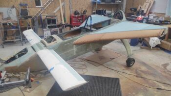
Today was all about working on finishing up the fitting, cutting and construction of the strake bottom skin foam cores.  I also did a lot of assessing and trial fits of both the GIB strake windows and the fuel site gages.

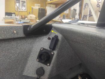
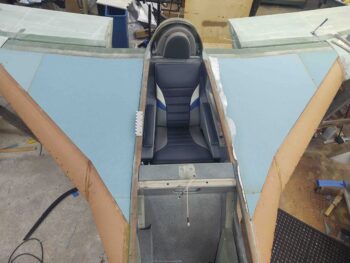
Both the GIB strake windows and fuel site gage positioning are both heavily influenced by a specific GIB passenger body part: the elbows.  Precisely that I modified the position of the BAB baffle to allow for more elbow room into the strakes, then I have to allow for and reserve that aft triangular corner piece of real estate for the GIB’s elbows.  This pushes the aft edge of the window just a hair forward and the fuel site gage as outboard as possible while still being able to see the top of it from standing outside the airplane.

Obviously the passenger most likely won’t be sitting in the aircraft during ground refueling ops, but a key consideration in my configuration is allowing my fuel site gage cameras to get both a good viewing angle of the fuel site gage and also not have the view fully obstructed by the passenger’s elbows.  So again, the more outboard, within reason, the better.

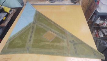
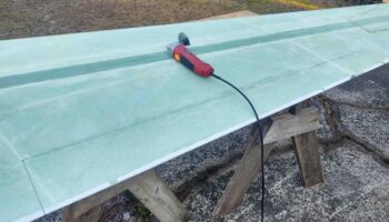
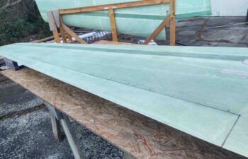
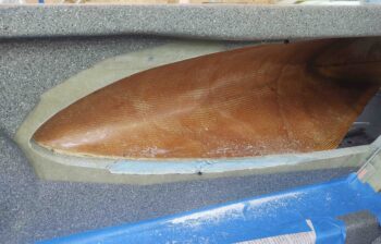
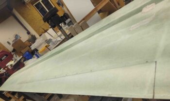
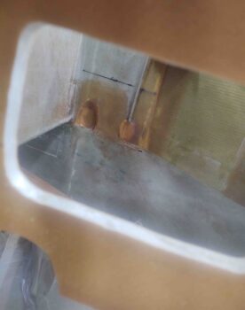
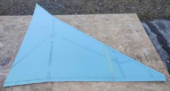
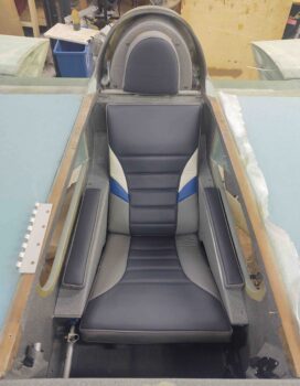
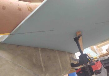
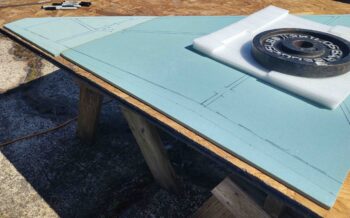
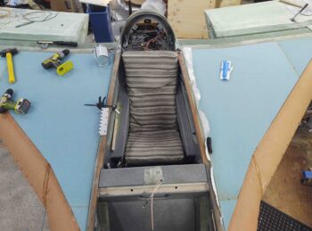
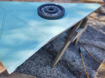
After sitting on my keister in the back seat for a good while, and my initial rough outline of the GIB strake window made, I then took the lower left strake skin foam core outside for a trim.

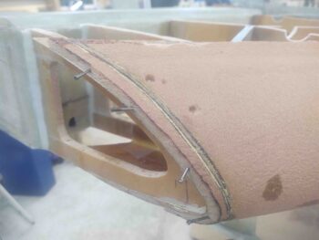
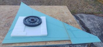
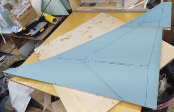
Here I’m trimming the aft edge to length.

As you can see here.

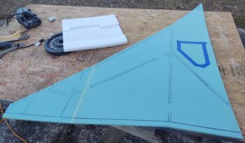
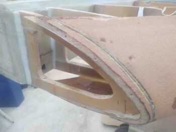
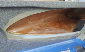
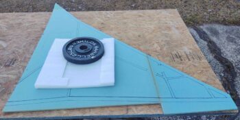
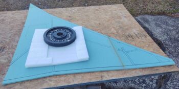
I then beveled the aft edge at 1.1″ this time.  Of course after I checked it I like the fit 1.0″ better, so I’ll be tweaking it just hair.  Should’ve just followed the plans eh?

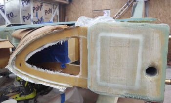
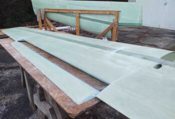
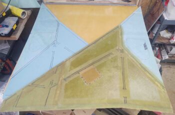
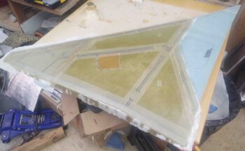
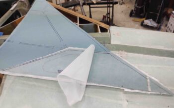
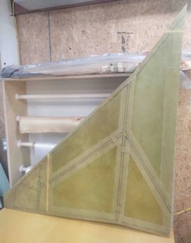
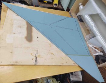
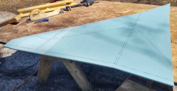
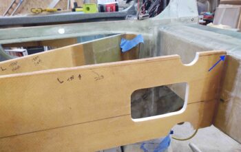
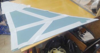
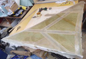
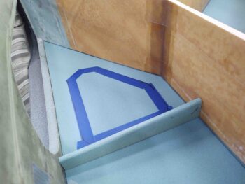
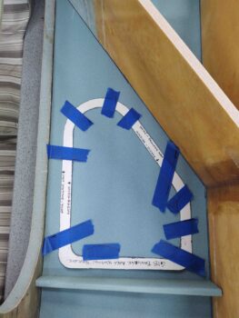
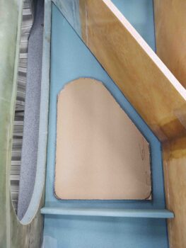
I then drew my actual outline (initial) of the GIB strake window.

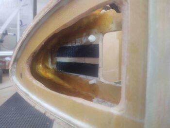
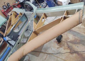
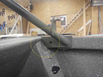
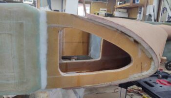
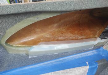
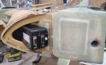
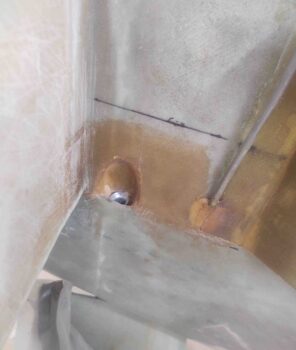
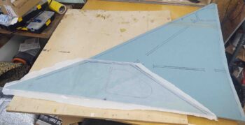
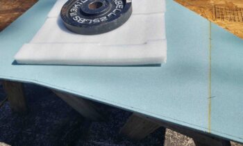
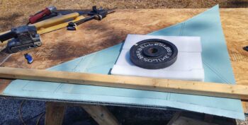
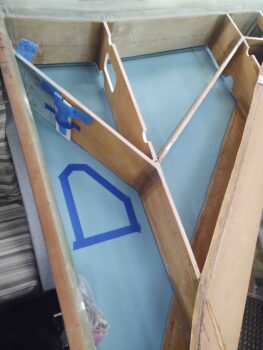
Here’s another shot.  Note the short cross foam piece that connects the fuselage sidewall to the R23 rib. This diminutive guy will serve a few purposes.  First, it will keep stuff from sliding back onto the window during flight.  I know in the back of Marco’s Long-EZ during Rough River trips we have a lot packed in there, and nothing really to keep stuff secure and from sliding aft over the window.  Nothing horrible or overly annoying, but it would help to have a “catch” if you will.

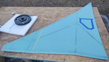
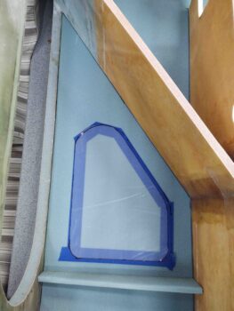
Next, with the GIB elbow room mod taking the BAB a lot further aft, to help with loads between strake and fuselage I figured I’d add this in for a little added strength. I’ll also do another “mini-baffle” like this at the top about 12″ forward of this one.  On the left that will be even more critical since pax often ingress/egress the back seat over and on the left strake top.

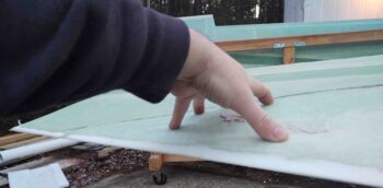
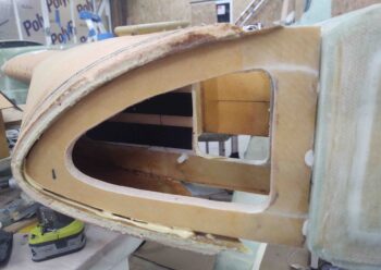
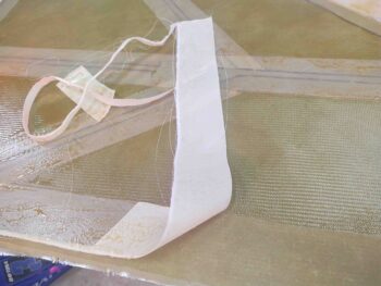
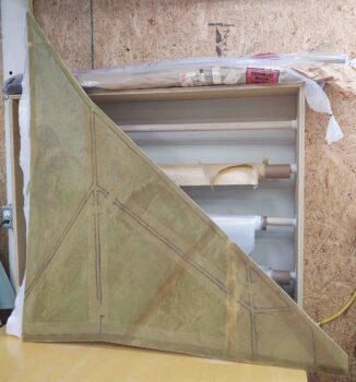
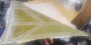
Since I didn’t have tracing paper I used clear plastic to mark out the interior outline of the GIB strake window.

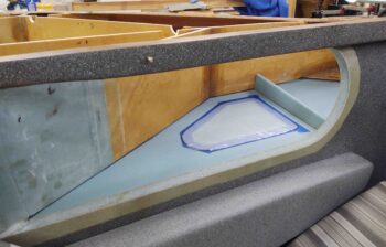
Of course airplane building and feature design is all about trade-offs and compromises.  I would prefer to increase the size of the window going forward a bit, but I want that mini-baffle there in that spot and symmetrical both left and right.  I’ll most likely install an O2 bottle in the baggage area, mounted to the “external” sidewall, so I need most of the fuselage sidewall from aft-to-forward strake opening clear.

Moreover, as was pointed out in a CSA article on these things, the GIB strake windows tend to be a bit heavy.  In the article the builder went with 1/8″ plexiglass simply because it was strong enough and, moreover, it was clearly half the weight as a 1/4″ plexiglass. Well, my strake windows split the difference at 3/16″ thick, and these are not feathers. Total added weight for the size windows I have shown here will be about 1.5 lbs.  Obviously bigger windows means more weight.

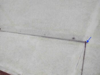
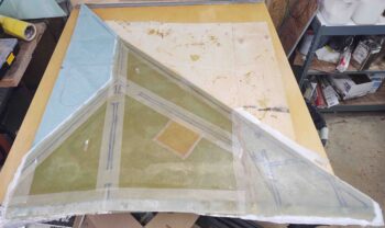
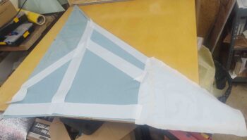
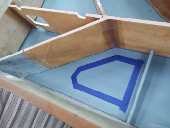
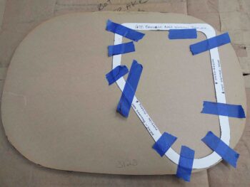
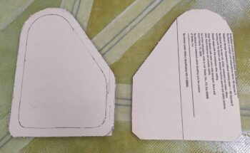
I then transferred the viewing area of the window (inner line), which is also the cut line on the bottom, external side of the strake… once it’s finished for paint.  The outer line is the size of the actual “plexiglass” (mine are airline windows) that will then have BID securing them in place up to the inner line.  For more viewing area, as in a bigger window, I didn’t follow the recommended 1″ border as proposed in the CSA article, but rather cut the border down to 0.7″.

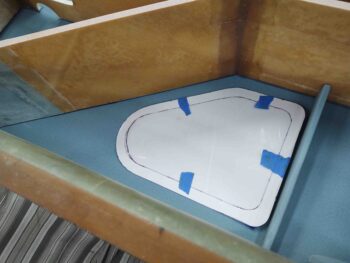
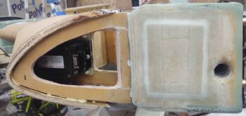
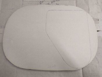
I then finished up my GIB strake window template by cutting out the center area.  Again, the interior template line actually denotes the exterior/external cut line (bottom strake surface) where as the outside template line is for inside the baggage compartment.

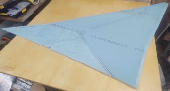
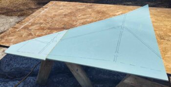
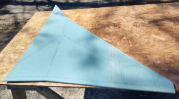
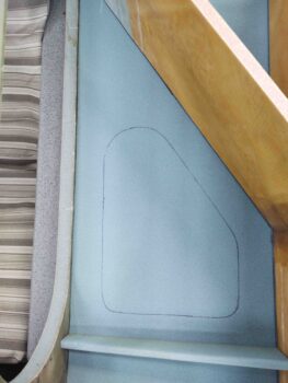
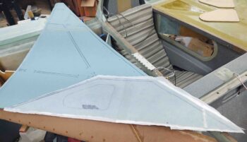
I then marked the interior template line on the foam.  This gives me the location of the window and an idea of the viewing size.  Plus, by only marking the inner line if later on I get a wild hair I won’t do anything stupid like cut the outer line all the way through, which is not how the install process is supposed to go!

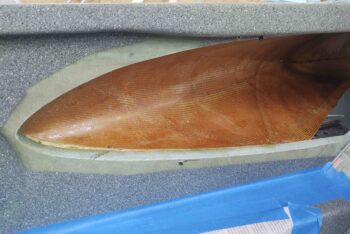
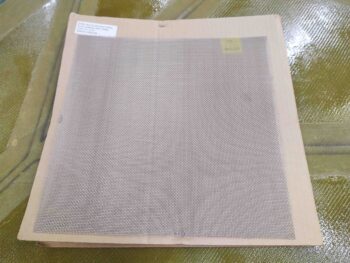
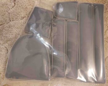
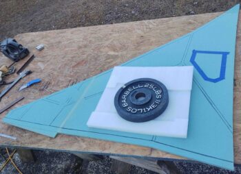
To get the window weights and also have the them ready for install, I used my template to mark the outline on the first of two of my surplus airline windows.

Read to be cut.

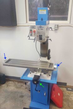
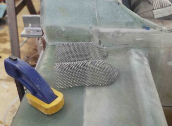
I then cut it out using my Skil saw (yup!).

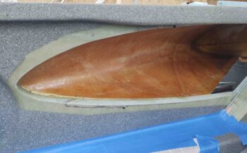
And here’s the second one cut out as well.

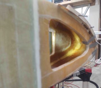
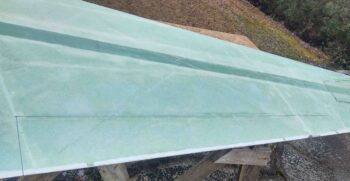
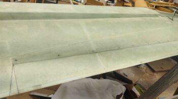
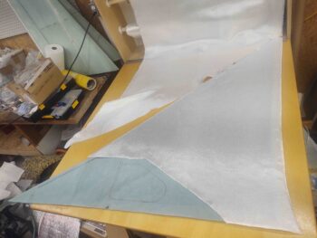
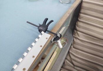
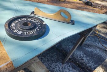
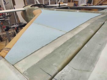
With my GIB strake window planning machinations out of the way, I then glassed the baggage area floor of the lower left strake skin foam core.  Since it was later in the evening and the weather is a bit chilly right now (slightly cooler shop), and plus liking the wet out characteristics on a large layup that will get entirely peel plied, I went with MGS vs EZ-Poxy for this layup.  Clearly I plan on doing the remainder of the left strake bottom interior skin with EZ-Poxy.

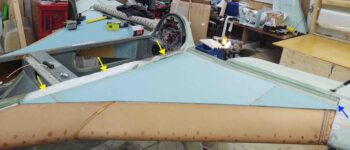
My last task of the evening was to knock out the fitting, cutting and assembly of the right strake bottom skin foam core.  I have to say I’m very pleased that fitting the bottom skins really isn’t that much more difficult than the top skins, as I had suspected it might be.

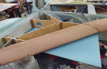
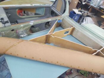
A bit later I micro’d the forward and outboard foam triangular pieces to the larger main foam piece to make up the lower right strake skin foam core.

I hen left it to cure overnight. Tomorrow I’ll trim and shape the aft edge and start the 1-ply BID layups on this skin core as well as finish up the left bottom skin foam core.


Chapter 21/26 – Strakes & Seats

Today I had planned on starting out on the lower left strake skin foam core and get the pieces micro’d up and curing before pulling the peel ply and cleaning up the top right strake skin core… however, something big changed my work order!

According to the original FedEx tracking # I was due to receive my upholstered seat cores tomorrow (Sunday) but before I made it out to the shop they were delivered.

Here’s the first bag of upholstered bits that greeted me upon opening the box: the headrest pads and armrests.  At first I thought they had gotten the leather colors wrong because the slate gray looked so blue . . . hmmm?

So out in the shop I quickly pulled the peel ply . . .

then razor trimmed the edges and cleaned up the right top strake skin layup.

I wanted to get the right strake top skin core in place to both test fit it and get this shot.  I had to vacuum out the back seat and stuff all the wires back into the D-Deck/GIB headrest.

The headrest pad is temporarily taped in place, which is why it’s a bit off kilter here.  I really like the lighter gray in the seats, and wish I could have gotten a bit more of it into the overall upholstery color scheme, but with them in place I have to say I’m extremely happy with how they came out.

I sat in the back seat for a good half hour and they are really comfortable.  I’ll also reiterate that with the thigh support sump installed, at 5′ 11″ I’m near the upper limit of passenger height for anybody going on more than just a quick local flight.  I’ll also note that when I sat in the back with the extended strake openings that my elbows naturally went into the strake openings…. so the “elbow room mod” is a must for passenger comfort in my opinion.

After test fitting the upholstered back seat cores (I’ll check out the front seat in another day or few, lots of stuff to reorg and clear out up there) I pulled out another sheet of 3/8″ Divinycell PVC foam and started fitting the bottom left strake skin core.

Here we have the bottom left strake skin foam core inboard edge along the fuselage marked and trimmed to fit.  With a flatter vertical surface it’s actually easier to get a tighter fit on the bottom skin core than the top core as the longeron curves a bit on the top.

I then marked and cut the aft outboard triangular piece and the very small inboard front triangular piece and micro’d those to the big foam piece to complete the bottom left skin foam core.  After it cures overnight I’ll take it outside like I did the top skin cores to mark and shape the aft bevel that mates up to the CS spar’s bottom beveled edge.

I’m tentatively calling Chapter 26 – Upholstery complete, given I still need to do a final fit check of the front seat cores. Also, cause I go easy on myself (wink) I planned for 3 days on the lower strake skins since I have the baggage area and GIB strake windows to contend with.

Chapter 21/22 – Daily strake layup

I started out today by pulling the peel ply, trimming the edges and cleaning up the 1-ply BID interior layup on the left strake top skin core.

I then got busy on the right strake top skin foam core.

I measured and marked a line 1.3″ aft of the line I had scribed following the front face of the CS spar.

I then trimmed the aft edge at this new 1.3″ line.

As I did on the left side, I flipped the foam core right side up and marked a 0.3″ reference line from the aft edge.

However, this time I went back and remeasured the top bevel of the CS spar.  I was getting about a 1.2″ wide bevel vs the 1″ I had quickly measured before.  I thought I would try using the entire 1.3″ initially for the bevel on the foam core and see how that went.

Well, that exercise told me two things.  First, about 1″ to 1.1″ works best on the top foam core bevel, so I adjusted it as needed.

The second thing was it was clearly time to knock down the tops of the ribs where they intersected the CS spar so as to ensure the top skin aft bevel mated correctly with the CS spar bevel.  So I spent about 45 minutes trimming and sanding the strake ribs and baffles on both sides to get them ready for both the top skins, and the T-Hat layups.  I don’t have an end-result shot here, but will point that out as I’m working the T-hat layups.

Another issue I had was when I test fitted the left strake top skin core.  The outboard edge (blue arrow) was barely fitting and something was knocking the entire skin core outboard by about 1/8″.  I found the culprit to be the inboard BID flap that is required per plans to come up from the bottom skin and overlap along the top surface of the longeron (yellow arrows).

The problem is that when getting all the glass wetted out along the edge of the underside skin layup, invariably some epoxy goes past that edge.  Thus, along about 2/3rds of this unwetted flap is a hard cured overflow edge that is —not surprisingly— about 1/8″ wide.

The original plan’s method has you glass the top skin then mounting it while the epoxy is tacky, so this flap edge isn’t really an issue. But if you let the skin cure fully then the problem I discovered rears its ugly head.

However, in looking at other builder’s sites I found that Ary Glantz found the solution to this problem: he glassed the underside skin sans flap, then simply laid the glass up (all but the aft 9″) on the LONGERON side first, let it hang down, then mounted the top skin.  Once the skin was in place he simply folded that flap up under the top skin and was done with it (all but the aft 9″ being in the accessible baggage area).  A big thanks to Ary for such a simple solution!

Since my seat cores are back at Oregon Aero getting upholstered, I then threw a seat pad into the back seat and sat back there to assess possible mounting locations for the GIB map light.  If I was going to have it attached inside the strake opening —which I’m not after looking at it— I would have created a hardpoint or embedded a nutplate assembly on the bottom surface of the right strake top foam core.  But I determined that to actually be usable as a map/reading light it needed a bit higher… like shown here on the longeron. Again, my main concern at this point was determining if I needed to do anything to the right strake top foam core in regards to securing the map light.

I then grabbed this shot as I was climbing out of the cockpit,  Note the fuel site gage laying on the left strake top.  I also played around with the positioning of those as well and have an initial idea where I want them… the fairly typically spot they go.

I then cut the big pieces of BID and prepped the peel ply for the right strake top underside layup.

Many hours later this was the end result (think I had a dirty camera lens . . .). This clearly meets my current one-strake-skin-layup-per-day requirement (grin).

With that I left this to cure overnight.

Chapter 21 – Left strake top skin

Today was all about the top left skin, although admittedly I had planned to do a whole lot more.  Funny how these builds work out with getting much less done in a day than planned!

I started out by setting up a workbench outside since my shop is a bit crowded at the moment.

As per the Feather Light leading edge strake kit instructions that I have on hand, I marked a line 1.3″ aft of the aft line I had marked on the underside of the left strake skin foam core. The marked line follows the very front face of the CS spar, so that for the matching bevel angle to be made on this foam core aft edge, it must have a reference…. hence, the initial CS spar face line.

I trimmed the aft edge of the left strake top skin foam core at this 1.3″ line, and then flipped the top skin with the top side up.  I then marked a line 0.3″ forward of the aft edge to use as yet another reference line.  The actual aft edge bevel on the CS spar is 1″ from the lower edge moving aft, so this matching edge interface needs to be the same on the foam core. (Ok, so initial cut is 1.3″ but it needs to be just 1″ for actual fit).

I then flipped the foam core back upside down and used this new 0.3″ mark to match the top surface (facing down at this point) to the edge of my workbench.

I then used the Fein saw to get rid of a good bulk of foam and followed it up with my goto 32 grit hard sanding block.  This last step I should have thought out better beforehand as I think 32 grit is a bit too harsh on that thin trailing edge. I had a few spots that broke out, but nothing that just a bit more flox (read: added weight) won’t cure. I’ll be more careful and judicious in my sanding practices on the remaining strake skin foam cores.

I then test-fitted my left strake top foam core.  After a bit of minor sanding in the very inboard corner, it fit a treat.

I then spent the next 4 hours glassing and peel plying the underside of the left strake top foam core.  It’s been a while since I’ve done a larger layup and the sheer amount of epoxy used just to glass one ply of BID to a piece of foam is impressive.

After today’s glassing experience, I’m re-setting/lowering my expectations and goals to finish one of these skin cores a day.  With the shaping, glass and peel ply cutting all occurring pre-layup, it’s quite a production all simply to get a ply of BID onto a flat surface. As I told my buddy Marco, these layups are “simple in theory and a prolonged ass-whooping in reality.

And I’m sticking to my story… ha!