Chapter 22 – Heat exchanger whole again!

This morning I woke up feeling like hammered dog crap… not good with a nasty cold.  It came on immediately and of course I’m not sure how long this will last, but the bottom line is that any shop build tasks is not happening today.

Since I was feeling less than stellar, I took the opportunity to spend a few hours on my website.  I parsed out the last few weeks of Blog updates to their respective chapter build logs.  I then backed up my website and updated my site to the latest version of WordPress.

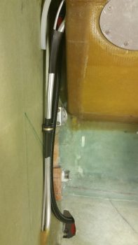
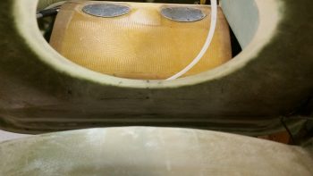
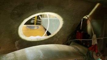
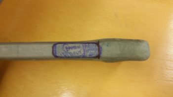
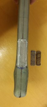
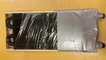
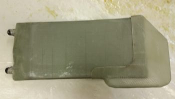
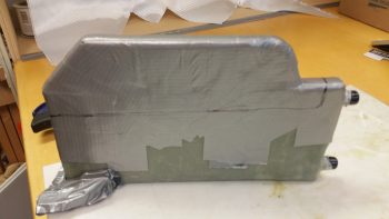
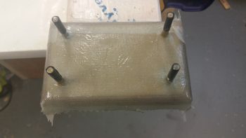
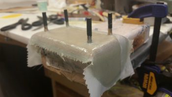
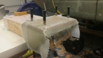
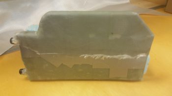
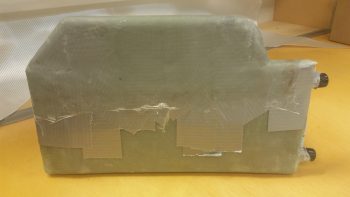
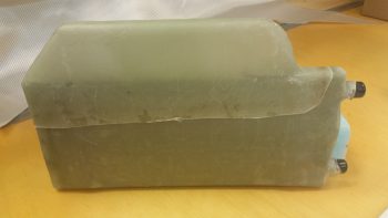
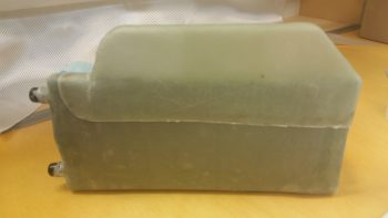
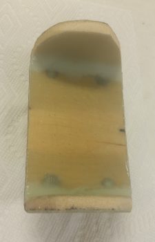
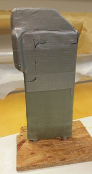
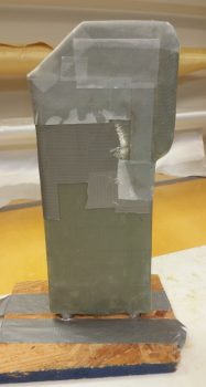
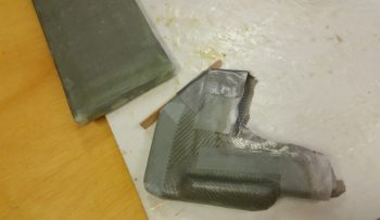
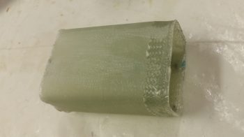
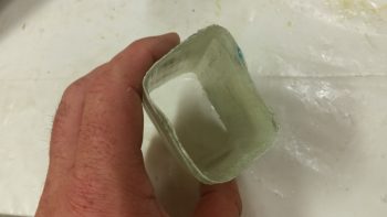
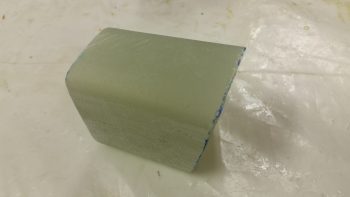
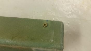
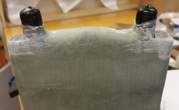
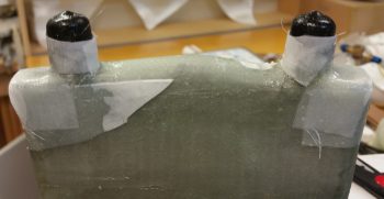
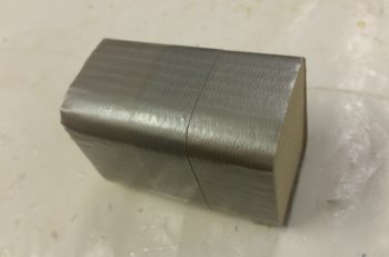
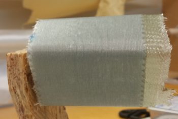
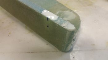
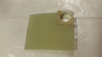
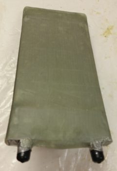
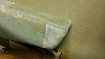
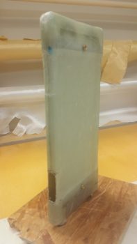
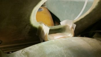
I actually went down last night after I finished yesterday’s post to pull peel ply and razor trim the first round of layups that secure the heat exchanger halves back together, with the heater core secured inside.  Except for the corners, which I basically just trimmed away, all the layups looked fine.  Here’s a shot of the top edge.

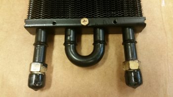
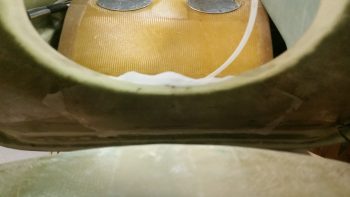
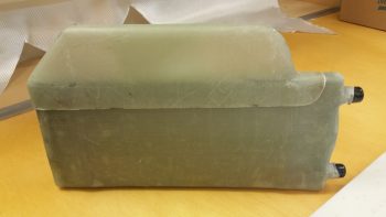
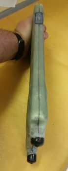
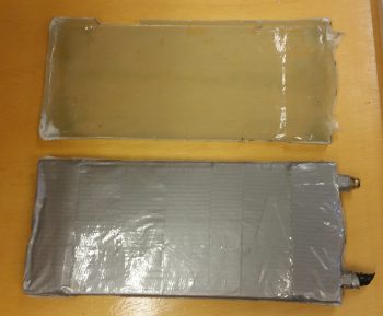
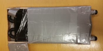
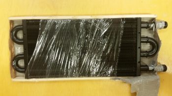
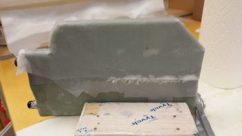
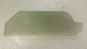
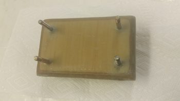
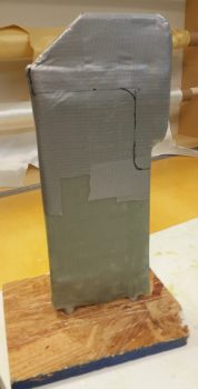
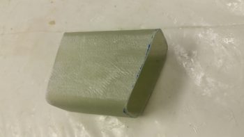
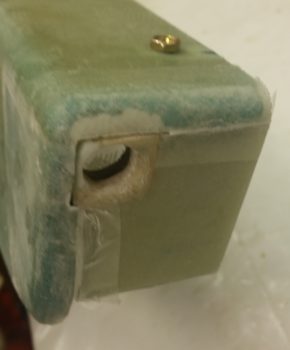
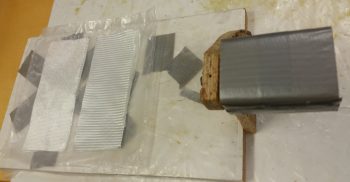
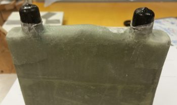
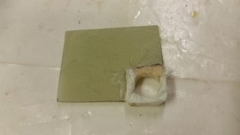
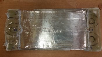
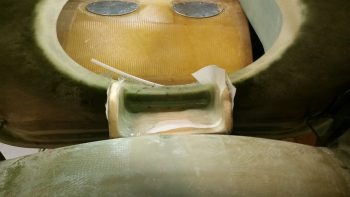
Here’s a shot of the inlet on the top side of the heat exchanger.  It still needs just a bit of cleanup on the edges, but beyond that I’m pleased with how the heat exchanger is coming along.

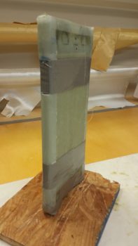
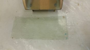
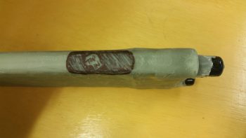
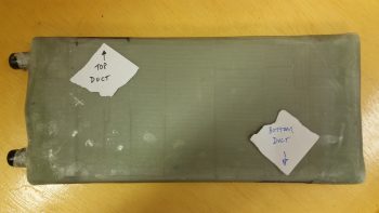
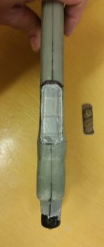
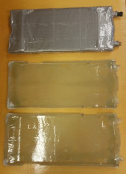
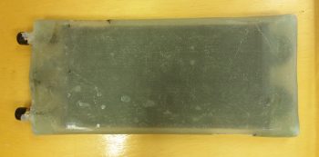
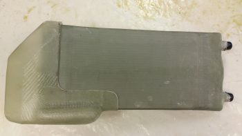
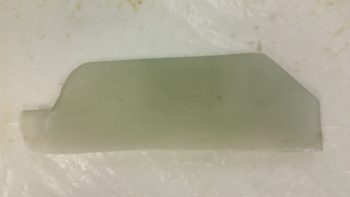
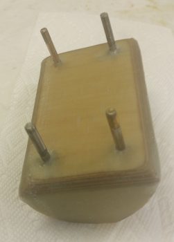
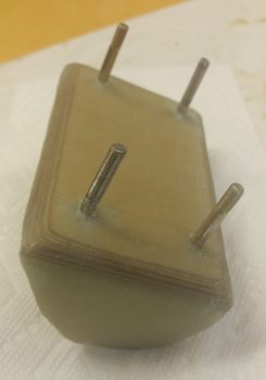
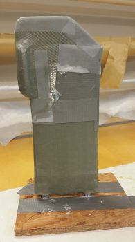
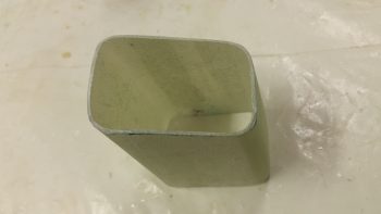
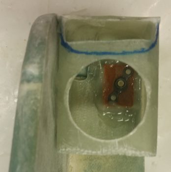
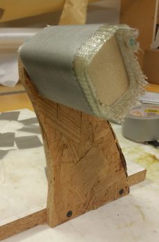
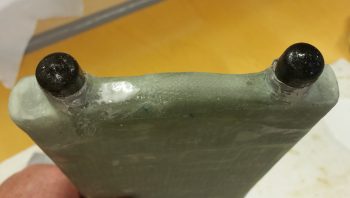
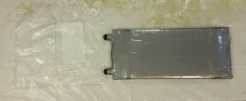
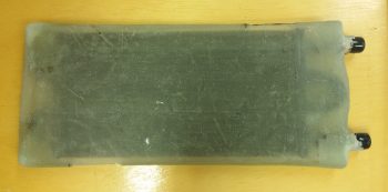
Here’s the bottom side of the heat exchanger.

Tomorrow I’ll be heading up (if I feel better) to visit some friends in the Dulles area, so not much building going on tomorrow as well.


Chapter 22 – Oil pump bracket installed

Today I started out by pulling all the tape off of the oil heat pump and checked the clearances both front and aft.  The clearances thankfully looked good.  As a side note, with the rubber vibration pads, I can tweak the clearance biased either forward or aft a bit just by the amount of torque I place on each mounting bolt.
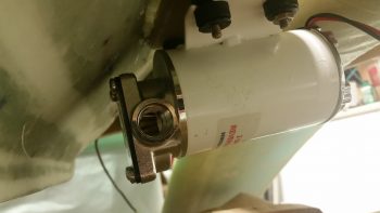
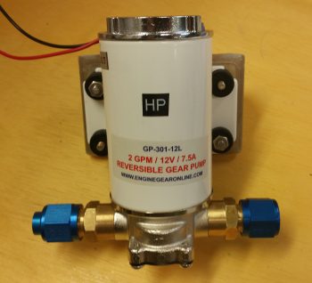
I then placed the oil pump fittings back in place, but this time I went ahead and put the AN hose fitting that will go on the end of the oil feed line that heads towards the heat exchanger.
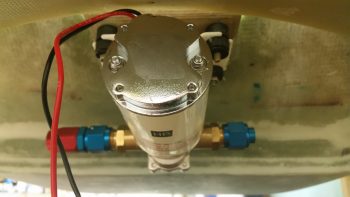
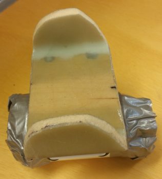
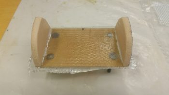
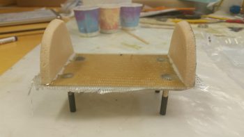
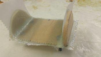
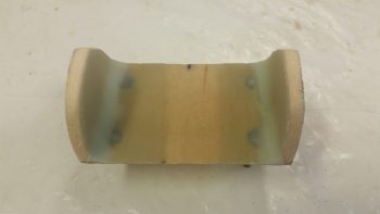
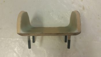
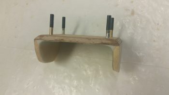
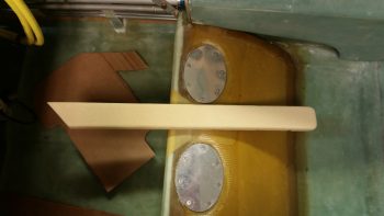
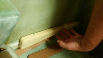
Here’s a shot of the cured and cleaned up oil heat pump mounting bracket.
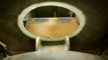
And another shot.
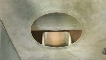
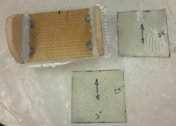
I then prepregged the next and final round of glass for the oil heat pump mounting bracket installation.  I laid up 2-plies of UNI over the edge of each foam upright support tab (after adding micro slurry to the foam and a bit of flox as a transition at the front edge with the seat glass), and then a 2-ply BID tape along the bottom side intersection of the bracket and the back seat (see below).
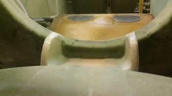
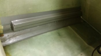
Here’s the final installed oil heat pump mounting bracket.
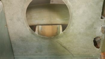
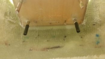
In addition to the 2-ply BID tape, I also laid up a 2″ x 2″ 3-ply BID tape in the center area of the bottom side bracket to GIB seat back for a total of 5 plies of BID right in the middle area of the bracket.  I couldn’t lay up a more than just the edge on the outer 1″ of each side of the bracket since the bolt studs are in the way (the ones with the black tape in the pic below).
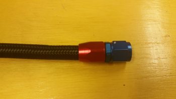
I then got to work building the oil pump to heat exchanger hose, via the 1/2″ to 3/8″ reducer… which this hose will actually attach to.  I slid the outer housing of the AN-8 fitting into place until it bottomed out (red piece).  The blue tape behind the outer housing was to let me know if the blue fitting piece was pulling the outer housing off the hose more than it should.
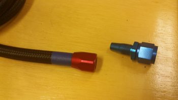
I then carefully threaded the blue fitting piece into the red outer housing piece to hand tight at first, then I used a couple of crescent wrenches for the final tightening.  Not shown here is the blue tape I wrapped around each component to protect them from getting marred.
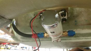
I then installed the hose onto the lower reducer fitting in the front left wall bulkhead of the sump tank.  I only tightened the fitting hand tight to get a decent idea of the hose length I needed.
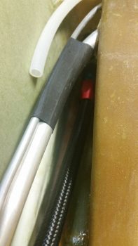
I then ran the house into the hell hole through the lowest hole in the GIB seat back.  There I cut the hose to length and followed the same process as before to install the opposite end hose fitting for connecting to the oil heat pump.
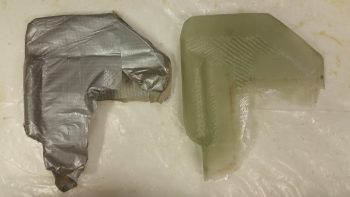
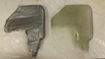
I then took a bit of time working on the heat exchanger ducts.   I trimmed them up a bit at the corner where they intersect and once they were able to play nicely together, I then taped it all up.

I then spent a good 45 minutes figuring out the exact location that the heat exchanger will get installed in the GIB area in the fuselage.  I was remiss to take any pics, but I was able to mark up the existing ductwork (that I have yet to permanently install) and the fuselage floor to know where the heat exchanger will get remounted.

Most importantly, for today, I was able to determine how the heat exchanger will get mounted inside its cover, and in turn, how the whole unit will get mounted onto (and atop) the current ductwork.
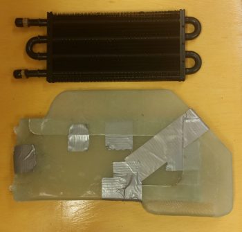
I was originally thinking I would use spacers, but since the locations I chose for the spacers were about 0.5″ from the center holes on the heat exchanger’s side frames, I chose to simply drill those out for a #10 mounting bolt.
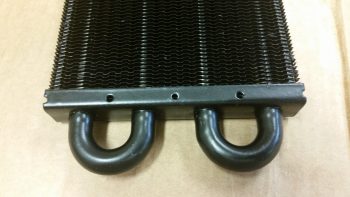
So I drilled out the center mounting hole on the forward end of the exchanger in short order.
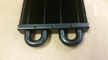
And test fitted a bolt.
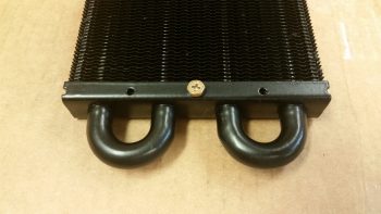
Then I did the same sequence on the aft end of the heat exchanger.
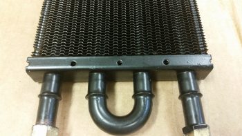
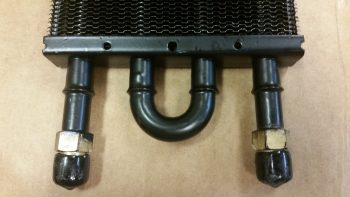
I then remounted the cover onto the heat exchanger, taped up the sides to ensure the heater exchanger was secure, I then shown a light up through one of the holes I had just drilled out in the metal side frame of the heat exchanger and marked it.
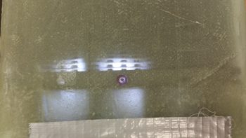
I then drilled a hole through both sides off the heat exchanger cover using the hole in the heat exchanger side frame as a guide.
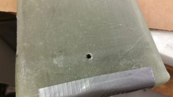
Again, I then test fitted a bolt to ensure the hole was good.
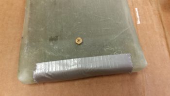
I then did the same sequence on the other end and ended up with another hole going all the way through the heat exchanger and cover.
Here’s the heat exchanger with the mounting bolts (test ones) in place.
I then cut out some mini air dams from 1/16″ (0.063″) phenolic to keep the air out of the end “caps” of the heat exchanger cover and flowing only through the finned middle area.

The cover extending over the “U” shaped tubes on each end was glassed that way to make glassing the cover over the heat exchanger much easier.  On the front side (shown below) it also created a straight wall to use as one of the interior duct walls for the exit duct of the heat exchanger.  Finally, it simplifies the heat exchanger lines and in my opinion makes it look better.  Still, there’s no need for the air to get “lost” in those end “cap” areas so I’m keeping the air path focused so that it will run only through the fins, which are kept warm by the hot oil running through the pipes.

[As a side note, you can see the blue dot close to the hole I drilled in the frame of the heat exchanger.  That blue dot was where I had planned on putting a spacer for mounting but obviously decided against it.]
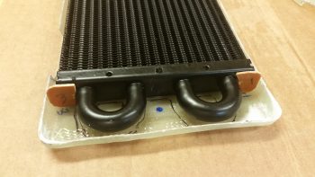
This pic is a little bit washed out, but you can make out the mini air dams at each corner of the heat exchanger.
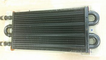
I then prepped the outboard wall of the heat exchanger cover by sanding the strips that would mate up to the frames on each side of the finned core.
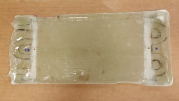
I then cut strips of foil tape and placed them on the inside of the heat exchanger to keep the heat as concentrated in that center area as possible as the air flows through it.
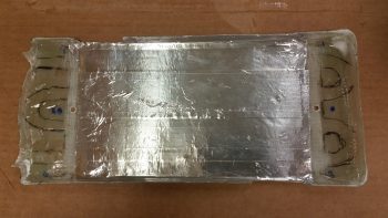
I then did one last test fit to ensure all my parts were good and aligned for what was next…
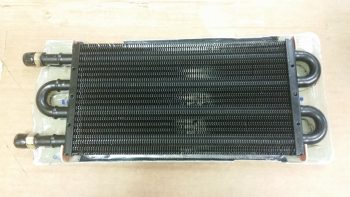
. . . hi-temp RTV.
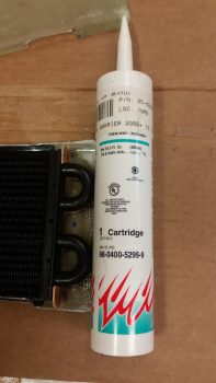
I ran beads of the hi-temp RTV along the areas I sanded that would mate up with the frame of the heat exchanger.  I also put a small bit around the contoured openings for the fitting posts.
Then, using installed bolts through the mounting holes as guides, I placed the heat exchanger in place onto the beads of hi-temp RTV.  I added a good dab of hi-temp RTV at each outside corner of the heat exchanger and set the mini air dams in place, and then ran a bead along the edges of each dam to hold it in place.

I then RTV’d the top of the heat exchanger edge frame, a thin bead along the top of each phenolic mini air dam, and again a small bit around the contoured openings for the fitting posts on the opposite side.
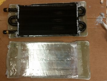
I then set the other side of the heat exchanger cover into place to entomb the heat exchanger once more.  I then taped the 2 halves of the cover tightly on each of the 4 sides of the heat exchanger.  I then placed the entire unit on a plastic box, added a bunch of drills and heavy batteries to weight it all down in place, and then ran to the store to buy a few groceries I needed!
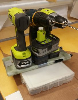
Upon my return, I had a quick dinner before heading back down to the shop.  In all, I let the hi-temp RTV cure a little over an hour total as I also cut the BID for the prepreg setups in prep for the initial glassing of the 2 cover halves back together over & around the heat exchanger.

I used only 1 ply of BID in prepreg setups, all 1″ wide.  Since there are some minor gaps that are understandably much wider if no pressure is placed holding the two sides together, I decided to make this a 2, possibly 3, step process (the extra one may be needed for the corners).

I taped a tight band of duct tape around each duct opening which worked well to keep the forward end (top in pics below) and middle sections tightly together.  I did need to use another bit of tape on the corners to close the gap at the bottom side in the pics below (which is the aft side of the heat exchanger).

I then laid up all the glass strips and peel plied them.
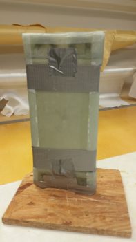
Tomorrow I’ll clean up the layups I did tonight and then prep another round of layups to finish closing out the seams in the heat exchanger cover and make it all one unit (It will be a finished unit when the upper & lower ducts are floxed into their respective places on the heat exchanger… as was shown mocked up earlier in this post).  I should also get an order I placed with Summit Racing so I’ll have more fittings on hand to continue working on the oil heat lines install.
 

Chapter 22 – It’s all about the oil!

Oil heat that is!

Again, the Chapter 22 thing might be throwing you off a bit since it’s electrical, but currently that’s where I have my oil heat system.  Thus, any discussion on the major ventilation system in this bird is married to the heat system, and ends up in Chapter 22. Weird huh?!  Yep, well, nothing about building Long-EZ’s can be considered normal!

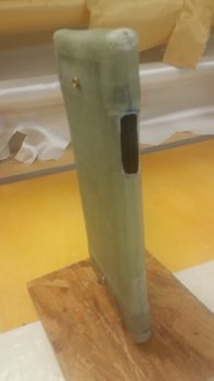
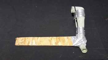
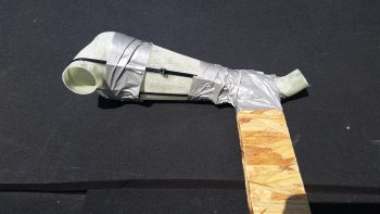
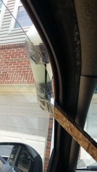
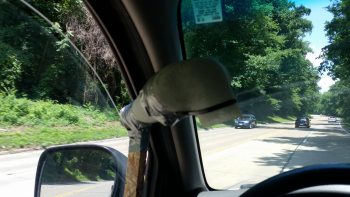
I had to run over to Andrews AFB to scarf up some money out of one bank to transfer to another bank for my upcoming purchase of the GRT EFIS I ordered under the discount that GRT offered for Sun N Fun 2017.  Since Andrews requires some Interstate/Freeway/ Motorway driving, I decided to test out my ventilation/heat system ram air inlet.  So I drilled a couple of holes into some chip board and then zip tied the inlet to the board.  Then I duct taped the zip ties to ensure they wouldn’t slide off.

I think it’s ready to go!

I then tested it out a bit in my driveway to ensure I wouldn’t kill, maim, hurt or embarrass myself . . . or anybody else for that matter.

I quickly realized from messing around with it above, that the inlet needed to be straight into the wind as best possible, but the angle for the rest of it really didn’t matter. Regardless (or “Irregardless” for Joe Coraggio!) at around 65 mph I was getting pretty good airflow coming through.  But then when I would push my hand up against the outlet I could pretty much shut down the flow.

So, quick assessment is that it seems to have decent airflow, but not good pressure.  And in this game sports fans, pressure is what it’s all about.  Looks like it’s back to the drawing board on this baby!  [Plus, I’ll do some more detailed testing . . . I got some ideas!]

After arriving back home I quickly got into the shop with the intent of getting the 2-ply BID base reinforcement layup for the oil heat pump mounting bracket layup glassed onto the aft side of the GIB seat.  I sanded down & prepped the area for the layup.

Then I prepregged 2 plies of BID, measuring 3″ x 8″, and wet it out with MGS 335 and fast hardener.

I then glassed in the 2-ply layup and peel plied it.

Here’s another shot at an angle to help with the exact orientation of this layup.

While the oil heat pump mounting bracket base reinforcement BID curing I then trimmed up the heat exchanger top duct piece.

I then test fitted the heat exchanger top duct piece back on the heat exchanger.

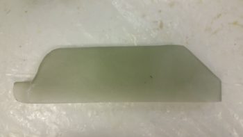
With both top & bottom ducts glassed, I could then verify the exact spots where the heat exchanger top & bottom inlets would go, given their dimensions match the ducts’ dimensions of 0.75″ x 2″.

Again, for better understanding where the heat exchanger ducts are located, I identified them with a couple pieces of paper.

I then took a few minutes to mark up the lines along the entire perimeter edge of the heat exchanger cover to split the case in two and remove the heater core with all its protective tape, etc.

First though, I cut out the heat exchanger duct inlets on both the top & bottom (inlet & outlet).

After a fair amount of pulling, prying and practicing my “How to converse with Sailors” speak . . . and not to forget the requisite injury, I finally got one side off of the heat exchanger core.

Following the shampoo mantra . . . ok, the “repeat” part . . . I was finally able to get the other side pried off as well.

I then got to work deconstructing the protective barrier that Stacey had helped me construct (could this be why it was so difficult to remove?!  . . .  just kidding!).  I took a fair number of pics on this process since I didn’t take any as we applied the protection before.

Here’s the final protective tape ensemble with the top & bottom 1/4″ wood caps that all served to protect the heat exchanger core while it was completely covered with glass.

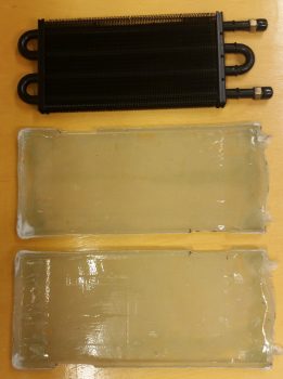
Finally, here’s the heat exchanger core with the two halves of the heat exchanger cover.

I then set the heat exchanger into one of the halves of the cover.

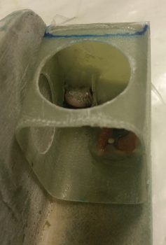
And then checked the fit of the heat exchanger core inside the cover.  Ahh, it’s awesome when a plan comes together!

Although I had mounted the oil heat pump to its mounting bracket much earlier in the evening, my last official build task of the evening was to flox and glass the mounting bracket to its location on the lower aft side of the GIB seat.

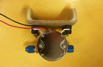
Before I get into that though, here’s a good shot (aft side) of how the oil heat pump will attach to the mounting bracket.

I pulled off the fittings and taped up the exposed areas of the heat pump as it sat on the mounting bracket.  I’m floxing & glassing the mounting bracket into place with the oil heat pump mounted to it to ensure clearance for the pump on both the forward and aft sides.

Although my off-center pic makes it appear more askew than it actually is, I must admit that during the initial mounting process of this thing, it did end up skewed off center about 0.070″ and is higher on one side by about 0.030″ . . . but that’s why we call it the hell hole right?! (As I told Dave Berenholtz: “Loaded up with flox on the edges of course this guy was like trying to balance a fish on a greased hard boiled egg!”)

I do have one more set of BID tapes to do on the bottom after the 2 sets of outboard vertical, 2 sets of inboard vertical, and 1 set of topside horizontal BID tapes cure.

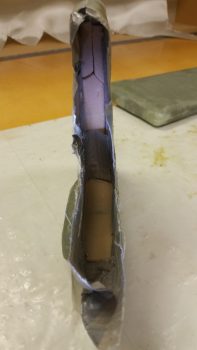
I took this shot at an angle for as good as view as we can get of the side layups, in the hell hole and all!

The layup schedule I used was a 3-ply BID tape on each outboard vertical junction (the foam tabs & seat back), with a 2-ply BID tape on the inboard vertical junctions (inside surface of foam tabs & seat back), and a 3-ply BID tape on the horizontal junction (1/4″ plywood bracket & seat back).  Tomorrow, I’ll do a 3-ply BID tape across the bottom intersection with the seat back.  Moreover, the 2-ply vertical junctions have a lot of overlap in the interior corners, thus there’s a good amount of “5-ply” BID in the corners.

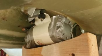
Finally, I wanted to show you all how I secured the pump/bracket assembly in place while I floxed & glassed it up.  What you can’t see in this pic is that the wood support is actually sitting atop my large shop vac.  In addition, If you look closely you’ll see that I taped 2 stir/ popsicle sticks on the front of the pump as a standoff pad so I could then just feel if it was pressed firmly against the fuselage bottom at the front and then concentrate on the aft side for clearance with the landing gear bow.

Tomorrow I’ll continue to work on the oil heat system ductwork, heat exchanger and finalizing the oil pump mounting bracket install.
 

Chapter 22 – All in a day’s work…

Seriously!

Today I started by pulling the peel ply off the heat exchanger bottom duct and cleaning it up.

Here’s the inside foam that I never got a pic of before I taped it up.  Just after I took this pic I dug it out of there.

Here’s a couple shots of the tape (with the foam removed!) that I used as the form and the actual bottom duct piece.

I then marked up the heat exchanger bottom duct for trimming with the Fein saw.

I then trimmed the bottom (outlet) heat duct with the Fein saw.

And then placed it back onto the heat exchanger cover to test the fit.  So far all looks great!

I then placed it inside the cockpit where it will sit once installed in the plane.  Again, the fit and finish are just right and all is a go at this time.

I then spent a good hour+ shaping a piece of urethane foam as the form for the heat exchanger top duct, and then taping it into place.  Again, the angle you see at the corner of the heat exchanger is the contour of the back of the pilot’s seat.

I offset the inlet and outlet of the heat ducts so that the inlet to the heat exchanger cover enters in the top aft part of the heat exchanger whereas the outlet exits out of the forward bottom part of the heat exchanger.  This offset maximizes the amount of time the air “sees” the hot oil-heated surfaces of the heat exchanger before exiting to warm up the cabin.

Also, I needed space in the inlet duct that runs from the main air feed into the heat exchanger for a heat restrictor butterfly valve.  This valve will allow me to keep the air out of the heat exchanger until the oil has time to heat up the heat exchanger and provide warm air.  Otherwise, once the valve upstream that redirects the outside cold/cool air is turned to heat, if the air is really cold and the engine oil isn’t up to temp, then that would make for a really cold “heater”!

I then glassed the heat exchanger top duct with 2 plies using a bunch of scrap UNI.  I then peel plied the layup.

I then spent a good 45 min playing around with the configuration of the oil heat pump to see exactly how I was going to mount it.  The manufacturer says it’s best to mount it with the mounting plate in the horizontal position, but they didn’t say that one or the other side had to be up.  So… I’ll be mounting it with the mounting plate in the horizontal position, just with the mounting bolts facing down.  In addition, I’ll be mounting the oil heat pump in the hell hole, at the bottom of the GIB seat just behind & under the round access hole in the GIB seat.

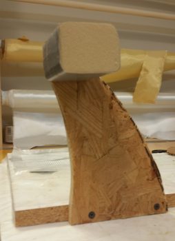
I settled on using my original 1/4″ Finnish Birch plywood mounting base, upside down, with a 1/4″ piece of foam on the top of each end of the wood base.  With the foam end pieces in place, it would make a Π shape, only flipped upside down to this symbol shown.  If I shaped each end foam piece to allow for the aft leaning GIB seat & the curve of the back of the seat, I could get all the 3 sides to contact the aft side of the GIB seat.  I could then flox & glass all these 3 sides (2 vertical, 1 horizontal) to the aft side of the GIB seat for a nice, strong oil heat pump mounting bracket.

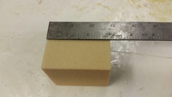
After figuring all the above out, I then spent another half hour finalizing the shape of the foam upright that will connect the sides of the 1/4″ plywood plate to the aft side of the lower GIB seat.  I used a scrap piece of the urethane foam to dial in the shape, and then once I got the shape set I transferred it to 2 other scrap pieces of foam and cut out the foam end pieces I would use on the actual oil heat pump mounting bracket.  To really put all you OCD/anal retentive types into an uncontrollable tailspin, get this: I used one piece of 1/4″ H45 Divinycell foam on one side and a piece of 1/4″ H250 Divinycell foam on the other.  I bet that’ll keep you cursing me when you can’t sleep for the next month thinking about it!  ha!

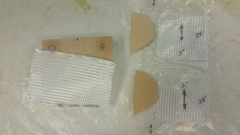
I then got my glass all sorted out for glassing the top side of the oil heat pump bracket. I prepregged 2 sets of 3 ply glass using a pair of the gazillion BID triangular pieces you end up with during these builds for each ply of BID.  The schedule for the prepreg setups are BID-UNI-BID with the UNI perpendicular to the bottom edge of the side foam pieces.  The single ply of BID on the top of the 1/4″ plywood bracket [that I previously floxed the 4 mounting bolts into] is for an initial ply of BID atop this wood base.

I made up just enough MGS 335 epoxy with fast hardener to glass the 1 ply of BID on top the 1/4″ plywood base.  As the layup started to get tacky I then floxed the 2 foam end pieces into place, ensuring their outboard edges were aligned with the sides of the 1/4″ plywood.

Here’s another shot of the oil heat pump mounting bracket.  You can see that I taped up the bolts to protect them.  Also, up until today I would have called this as the oil pump bracket being upside down, but now it is actually right side up.  Also, since I had just a hair of epoxy left over, I went ahead and made up some wet micro and micro’d the inside faces of the foam end pieces.

I then made up some more epoxy with fast hardener and wet out the prepreg setups.  You can see I labeled the prepreg setups with arrows so I know the direction of the UNI cloth, which will actually get laid up 90° to how their shown here.  I also whipped up some flox, which you can see that I used to put fillets in the corners between the foam and the wood base that I just laid up a ply of BID on top of.  At this point, the BID was still very much tacky, but was quickly on it’s way to curing.

I then laid up the prepregged 3-ply glass setups, 1 on each side and squeegeed out the air in short order with the top prepreg plastic.

I then peel plied the entire top inside glass of the oil heat pump bracket with a piece of 3″ wide peel ply tape.  It looks like I added a lot of wet epoxy, but in reality the epoxy was getting really tacky since it was fast hardener, and went it on like syrup vs wet epoxy.  It still did its job however in wetting out the peel ply, it just took a bit more “coaxing!”

And yet another shot of the glassed & peel plied top/inside layup of the oil heat pump mounting bracket.

I then took a break to eat dinner and upload a bunch of these pics to this blog.  When I returned the laid up oil heat pump glass was cured to at least a good 90% I’d say. I razor trimmed and easily pulled the peel ply and the layups looked good.

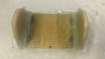
Here’s a couple more shots of the cured top/inside glass on the oil heat pump mounting bracket.

I then prepped a 4-ply prepreg setup for the bottom/outside layup for the oil heat pump mounting bracket.  The layup schedule for this glass, starting from the bottom ply up was UNI-BID-UNI-BID.  Both UNI plies were biased so their fibers ran straight from the top of one side, around the bottom, straight up the other side to provide a nice cradling type strength to the layup.

After I glassed the bottom/outside of the oil heat pump mounting bracket, I then of course peel plied it.

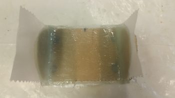
Here’s another couple shots of the glassed bottom/outside of the oil heat pump mounting bracket.

By this point in the evening, the heat exchanger top duct layup was cured so I then pulled off the peel ply.

I then removed the whole assembly from the heat exchanger (forcibly!), removed the tape and foam from the inside of the top duct piece, and then quickly trimmed the top duct piece’s edges.

I then set the top duct piece back onto the heat exchanger to test the fit.  It looks good and I don’t see any issues at this time.  It’s way too late to fire up the Fein saw and trim this duct piece tonight, but I will get it trimmed within the next day or so.

In the amount of time it took me to write all the blathering above, when I went down to check on the oil heat pump mounting bracket bottom/outside glass layup it was cured. So I spent a good 15 min cleaning it up so I could knock it out and include in tonight’s blog.

These pics below kind of make it look like a dead bug, but here’s the cured bottom/outside layup on the oil heat pump bracket.

And here’s another shot of the top/inside of the bracket to see how the two sides came together.

Tomorrow I won’t get any building done since I’m spending the day with some friends who are moving out of the area in a few weeks.  I will be back on the build hot ‘n heavy on Monday though.


Chapter 22/24 – GIB Headset Jacks

Today I started out by cleaning up the 2 small layups that overlap onto the two internal sides of the PTT 1/4″ phenolic mount and the foam/flocro recessed PTT button housing junctions.

I then identified my desired positions for the headset jacks and drilled the two 3/8″ holes for those.  I then of course installed the jacks to ensure they fit  . . . which they did (yeah!).

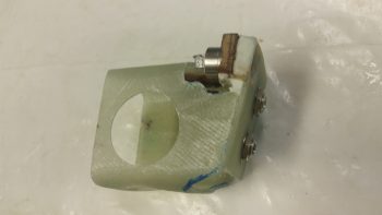
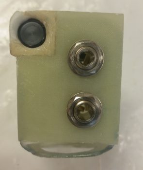
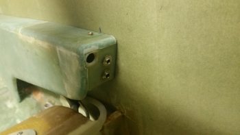
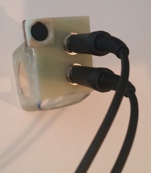
So, here’s the forward Left GIB mounting/PTT button/headseat jacks bracket that will reside on the front face of the left GIB armrest.

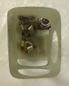
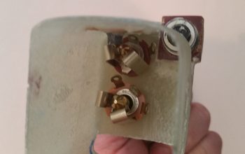
Here’s the business end showing the internal side of the bracket.  Yes, it’s a bit tight in there, but it all fits fine.

And here’s an “action shot” showing the armrest front faceplate set in place.  I still have just a bit of cleanup work to do to get it all squared away cosmetically, but structurally –beyond actually installing it to the sidewall– I’m done.

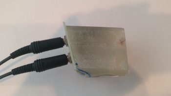
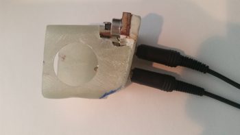
To verify that there were no clearance issues with the headset plugs, I took the bracket assembly upstairs and hooked up one of my headsets.  Looks good!

Here’s close to the actual angle that the GIB will experience when plugging in their headset.

And from the other side.

The internal clearance with the plugs installed is fine as well.

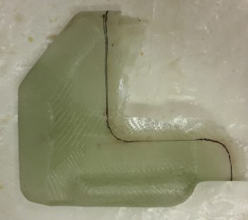
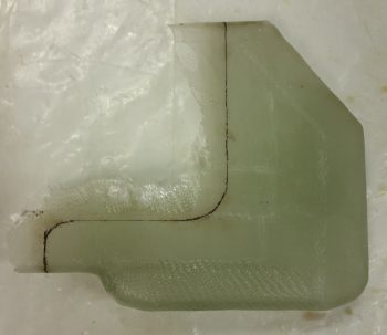
I then set my sites on knocking out the lower cross connect duct that comes out of the oil heat exchanger and transits the hot air into the ductwork.  I played around for quite a while to figure out the exact duct size, especially since it was a variable along with the height of the heat exchanger off the cockpit floor.

Ok, my “standard” ducts are 3/4″ wide x 2″ high, which provides a close approximation air volume wise as 1.5″ round SCAT tubing.  The optimal height of my heat exchanger off the floor is 0.9″ (vs. 2″ high), so I clearly had some hard configuring to do.

Since the heat exchanger sits over (actually “adjacent to”) the existing ductwork that I just created –with the majority of it being over (again, “over” as in covering) the horizontal air feed to the GIB– I decided to use the area UNDER the horizontal air feed that is just outboard & to the left of the heat exchanger for a wider/flatter duct, thus letting me reclaim the approximate amount of volume lost by having to shorten my duct to 0.9″ (vs. 2″ high).

Thus, in the first pic below, you’ll see what looks like the goiter-type protrusion that sticks out on the bottom of large ocean-going vessels.  This is the widened horizontal segment of the lower heat exchanger duct, which then makes a 90° turn upwards along the forward edge of the heat exchanger until it empties out into the ductwork (near the angled part).

Additionally, the angled corner you see in the pics below is actually the intersection of the heat exchanger outlet duct where it meets the pilot seat back (NOTE: In the pics below, the heat exchanger is mounted into the board with the aft edge down).

I then laid up a bunch of UNI scraps as the first ply of glass and then laid up a ply of BID over that.  I peel plied a bunch of the edges and then took off to have dinner with a buddy of mine.

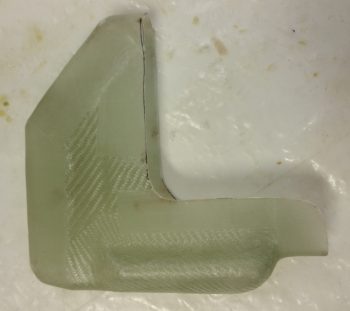
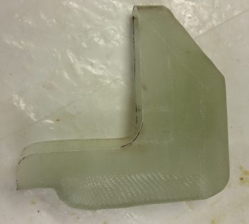
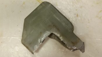
Upon my return from dinner, with the glass at a perfect “green state,” I cut the short edge and the slanted corner glass right down the middle.  I then slowly worked the rather pliable glass off the heat exchanger and then did my best to ensure all the glass was sitting exactly how it was while it was on the heat exchanger… so it would be correctly shaped when cured.

Obviously, my other option was to let it cure on the heat exchanger, Fein saw it off in 2 halves, then glass the halves back together.  Not only did I want to avoid the weight, glass usage, and hassle & time of another layup, I didn’t want to accidentally cut into the heat exchanger cover that was just a scant couple of duct tape plies from the glass I was cutting.

Tomorrow I’ll shape & glass the upper heat exchanger inlet duct, as well as trim up the outlet duct I glassed tonight.  In addition, I’ve realized that I need to get at least the aft oil heat lines installed before I install the forward Left GIB mounting bracket (for clearance). So tomorrow not only will I build a couple of oil hoses, but I’ll also start work on mounting the oil heat pump.


Chapter 22/24 – Aft left armrest mount

Today I started out by removing the foam form out from the middle of the left GIB armrest forward bracket assembly that I glassed last night.

The bracket came out nicely with no glaring errors!

I had glassed it up a bit oversized, so I took a few minutes to measure out my bracket dimensions, mark up the bracket and then trimmed it with the Fein saw.

I then got to work notching the bracket in the upper inboard corner for PTT button housing clearance.  I also drilled some lightening holes: one on the inboard side and one on the bottom.

Here’s a good look at the corner PTT button housing clearance notch.

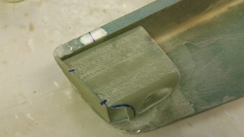
I also notched the front bottom lower edge since the face plate doesn’t come all the way down.  By moving the lower edge back a bit, there’s no way to see that the bottom bracket lip doesn’t intersect with the lower edge of the front face plate.

After some judicious sanding –mainly on the front angle of the armrest mounting bracket–   I taped up the inside of the armrest and then 5-min glued the mounting bracket to the front face plate.  I did this while keeping the face plate in its proper position at the front of the armrest.

After the 5-min glue cured, I immediately glassed the bracket to the face plate with 1 ply of BID in the corners for each of the interior intersecting walls, using micro fillets.

I then rounded up the left GIB mounting bracket’s nutplate assembly that I had made up a few days ago.

This time I taped up the edges of the face plate assembly in prep for these multi-tasked next steps.

I then laid up 2 more small plies of BID inside of the bracket: 1 on each interior side of the PTT button foam & phenolic mounting pieces.

I then floxed the nutplate assembly into place on the underside of the bracket’s top plate

With the face plate taped, I also micro’d the edges of the face plate to fill in any gaps between the face plate and the armrest inside edge.

Here’s a shot of the floxed nutplate assembly in place on the underside of the bracket’s top plate.

Here’s a shot of both the floxed in place nutplate assembly and the ply of BID on each side of the interior PTT button housing.

And one final shot of the ply of BID on each side of the interior PTT button housing.

Tomorrow I’ll drill the holes in the face plate for the 2 jacks for the GIB headset.  I’ll then flox the left GIB armrest bracket to the fuselage sidewall.  All that will be left then for finishing up the mounting bracket will be the wring of the jacks and PTT button.  I also intend to work on the oil heater heat exchanger ducts as well.


Chapter 22/24 – GIB area tidbits

Today I started off by prepping the corners of my recent heat exchanger BID cover for glass.  I had actually glassed on a couple plies of BID during the initial glassing of the heat exchanger cover, but with so much finagling of the glass to get it to lay down right, the corner plies were mangled beyond use so I just pulled off the blobs of BID and chucked ’em.

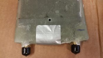
Now it’s time to remedy the exposed corners immediately adjacent to the AN fittings (black caps) on the oil inlet and outlet tubes of the heat exchanger.  I knifed some dead glass away and sanded the corner areas in prep for the 2-ply BID layups.

I then laid up 2 plies of BID on each corner and peel plied the layups.

I then got to work on the left GIB armrest forward composite mounting bracket that will also house the GIB PTT button & GIB headset jacks on the front face of it (which will get attached to this bracket frame later).  I used a 2″ thick urethane foam block for the form and cut the block 3″ long.

I then sanded the foam block form into shape, radiused the corner edges for glass and taped it up with duct tape.

I then cut out 3 strips of 3″ x 8″ BID and 2 strips of UNI the same dimensions for a total of 5 plies of glass.  I then put the glass into plastic for a prepreg setup.  I also mounted the  left GIB armrest forward mounting bracket form onto a vertical stand to make laying up the glass onto it much easier.

Here’s another shot of the left GIB armrest forward mounting bracket form attached to its vertical stand.

I then laid up the 2 sets of prepregged glass so that the layup schedule was a simple BID-UNI-BID-UNI-BID pattern with the UNI plies at a 30° bias, with each UNI ply in the opposite direction.  I then of course peel plied the layup.

Yet another shot of the 5-ply glass layup for the left GIB armrest forward mounting bracket.

With the same epoxy I also whipped up some micro to pour into a hardpoint divot that I had created at the left GIB armrest forward mounting point.

By this time, the layups on the two corners of the heat exchanger had cured.  I pulled the peel ply and cleaned up the layups while they were still in that nice “green” stage.

Here’s another shot of the layups on the two corners near the AN fittings of the heat exchanger.

Tomorrow I’ll continue to work on both the heat exchanger and heating/air ducts while also working on the left GIB armrest forward composite mounting bracket.


Chapter 22/24 – PTT & Heat Exchanger

Late Friday I laid up 1 ply of BID across the front face plate of the GIB left armrest.  I pulled the BID down through the hole in the foam recessed housing for the PTT button.

Well, when I trimmed the glass off on Saturday, unfortunately a good chunk of the foam came with it.  I then needed to repair it of course.  Being in a rush for a social engagement, I quickly wrapped up the PTT button in saran wrap & tape, and then set it in what remained of the hole and weighed it down.  I then whipped up some flocro and –using the taped-up PTT button as a form– rebuilt the recessed housing “frame” around the PTT button.

Here’s a shot of the left GIB armrest’s front face plate, with the repaired PTT button foam recessed housing.

I haven’t sanded down the repaired PTT button foam recessed housing to its final shape yet, but will get to it after the July 4th holiday festivities are over.  Still, here’s the aft side of the left GIB armrest’s face plate.

Today I focused on glassing the heat exchanger.  With help from my lovely assistant (Stacey is visiting from North Carolina and helped with both the prep and the glassing of the heat exchanger… and I have to say, it was great having an extra pair of hands on this somewhat challenging layup!  Thanks Stacey!) I taped on two 1/4″ thick rounded wooden runners on top and bottom (that I cut on the table saw Saturday), made some flat cardboard end caps for the U-shaped tubing on each end to make the whole cover a more even rectangular shape, and then wrapped it all in plastic.  I then taped it all up, first with duct tape, then with clear packing tape.

We then cut out BID to make up a 2-ply prepreg setup for each end.

We then wet out the prepregged BID and laid up the end pieces.  Then over the end pieces, we wrapped and wet out 3 individual plies of BID, one at a time around the entire middle area of the heat exchanger.  The corners did give us a hassle, so on the non-AN fitting end I used a bit of micro in each corner and laid up some “corner cap” pieces of BID.  I left the corners on the AN fitting side alone for now and will glass them during round 2 of enveloping the heat exchanger in glass.  After laying up all the glass, we peel plied it all and let it cure as we went out to meet some other friends for dinner.

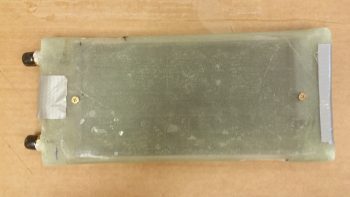
Above and below are actually shots of the glassed heat exchanger after I pulled the peel ply.

Tomorrow we’ll be celebrating July 4th, so no building is planned.  I do plan on getting a fair amount knocked out starting back full steam on Thursday.


Chapter 22 – Phase I Air Ducts complete

Remember, the oil heat system is listed in Chapter 22.

Today I started out by actually finishing up my blog that I was too tired to do last night.

I then sat down and went over some info my buddy Dave Berenholtz had sent me on oil heating, reread Nick Ugolini’s write-up in the latest CSA newsletter, and then proceeded to finalize my oil heat and fresh air intake ductwork plan.

I then went out to my shed, pulled out the table saw and ripped some urethane foam in 3/4″ wide pieces.  With the thickness of the foam being 2″ (I didn’t forget this time!), that makes for the perfect form –according to Nick U.– for making homemade fiberglass heat & air ducting.  According to Nick this glass ducting weighs about 25% of the equivalent length of 1.5″ round SCAT duct tubing.

I then cut each foam piece to length and radiused the outer corners.

For the piece running horizontally over the antenna cable channel conduit I had to create a trough along the entire length of the back side of the foam form.

I then taped the urethane foam form in place and marked the centerline.  Marking the centerline is a fairly important thing not to forget since it allows perfect alignment with the CL of the prepregged glass as it’s laid up.

I then cut the main air feed foam form to shape and length to run from the air inlet that I just drilled last night down to the lower corner to intersect the horizontal duct form that I just taped into place.  I then taped the main air feed duct foam form in place as well.
I didn’t get a pic of the last duct piece before I glassed it all, because it actually got mounted after the main air feed duct UNI glass was laid up to provide a dividing wall between the two ducts via the aft wall of the main air feed.
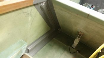
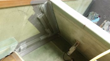
I then glassed the parallel duct aft of the main feed and overlapped the glass onto the main feed top to created two channels with a dividing wall.  The glass at the bottom edge of both of these leaning vertical upright feeds overlapped onto the bottom horizontal duct, so that when I glassed the bottom duct form it simply created one big layup with the 3 ducts all tied together.  In fact, these ducts will be very close to final configuration without much cutting or major work needed for the airflow to get to where it needs to . . . pretty cool, eh?!
Another cool thing about the layups for these ducts is that I did them ALL with leftover “trash” glass by using overlapping plies of UNI to create a 2-ply prepregged setup with each ply of UNI biased at around 30°-45° in opposite directions.

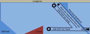
I’m calling this Phase 1 of the ductwork glassing & installation.  Here’s a diagram showing the ducts I glassed tonight:

And here are the remaining phases (a loose guideline of how this install will flow . . . I won’t necessarily be strictly adhering to it):

  • Phase II – Heat exchanger glassing
  • Phase III – Ductwork interface holes drilled and valves built
  • Phase IV – Ductwork installed with heat exchanger and valves in place
  • Phase V – Oil pump installed & oil lines run
  • Phase VI – Pilot seat area ductwork constructed and installed
  • Phase VII – Instrument panel forward ductwork constructed and installed
  • Phase VIII – Valve cables terminated and handles installed

Obviously I didn’t get to the left GIB armrest forward bracket, although I did spend a good 20 min today locating my 39/64″ drill bit to create the PTT button installation hole!  Tomorrow I plan on glassing the left GIB armrest forward bracket and should have it finished no later than Monday.  In addition, I plan on glassing the oil heat exchanger as well in prep for mounting it over (eg inboard) of the Phase I ductwork I did tonight.

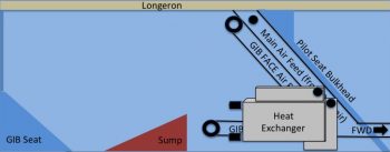
Here’s a general idea of how the heat exchanger box will tie into the ductwork that I glassed tonight:

It may a bit difficult to follow in diagram form, but after it’s glassed and installed it should become much clearer on how it all operates.


Chapter 21/22/24 – Ram air duct prep

Today I started off working for a couple of hours updating 5 electrical diagrams:

  •   A.   Switches, Breakers & Panel Lights
  • .99   Grounding Busses
  •   4.   Electrical System Components Map
  • 10.   Fuel System
  • 11.   Cockpit Lighting

I then spent a couple of hours on the left GIB armrest.  First off I DA sanded down the somewhat grotesque layup edges that where created when I added the top and front extension pieces you can see in the pic below.  Unfortunately, being in a rush to make up for some lost time on personal stuff today, I had one fuzzy pic and simply didn’t take any others.  I know: for shame!  The end result is not only did I radius the front edge and glass it with a ply of BID, but I also filled in some holes with micro in a few different areas on the armrest.

Moreover, I cut a square notch on the very top inboard INSIDE corner that will mate up to the GIB PTT button housing that will be incorporated into the sidewall bracket that will also house the GIB headset jacks.  In addition to the top curve, I also glassed the inside surface of the PTT button bracket notch I made with 1 ply of BID.  Of course all the layups got peel plied.  I’ll get a pic of all the interior layups tomorrow.

I then set my sights on getting the ram air inlet, expansion chamber and transition piece installed on the (current) exterior side of the fuselage.  I double checked my dimensions, moved my initial drill point forward and down just a hair, and then drilled it with a small pilot bit.

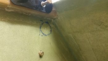
And Bingo!  Center of mass on the interior marked hole.

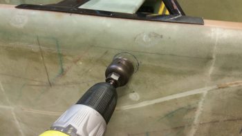
I double checked the overall configuration of how the ram air inlet, expansion chamber and transition piece would mount on the exterior sidewall (which will be inside the strake baggage compartment when the plane is finished).  I then loaded up a 1-1/2″ hole saw bit into my drill and literally pulled the trigger!

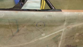
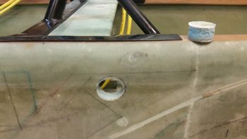
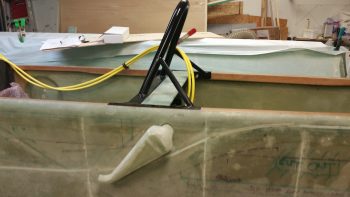
Here’s the initial 1-1/2″ diameter hole into the fuselage sidewall, obviously just aft of the pilot seat and just under the left longeron.  You can see the drilled out plug sitting atop the longeron.

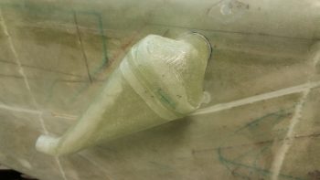
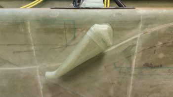
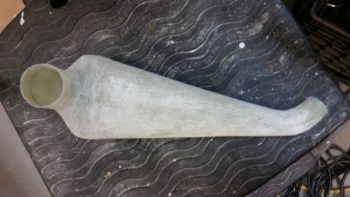
Here’s a couple of shots of my test fitting the ram air inlet, expansion chamber and transition piece into place.  The transition tube on this component is 1.5″ ID, which means I had to widen the hole out a bit for this piece to fit into place.  Also, I had to radius the outer perimeter of the hole a bit from around the 5 to 10 O’ Clock position for this thing to mount close enough to the sidewall.
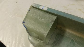
I intentionally glassed the 1.5″ ID air transition tube of the ram air inlet, expansion chamber and transition piece a little long so that it would definitely clear the inside surface of the fuselage sidewall.  However, the excess, overhanging tube edge will be cut down so that the transition tube edge is flush with the interior surface of the sidewall, since the air will immediately flow into the heating and fresh air ductwork at this point.
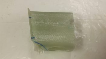
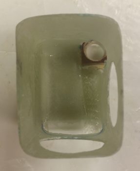
You know me, the peel ply king, and the one time I thought I could get away with not doing it, I ended up needing to sand this sucker down… well, in the end not all of it, but a good portion of it!  I call this picture: The Mummy in Repose …. haha!

Now, I need to research just how far away from the outer skin the intake needs to be mounted, so the ram air inlet, expansion chamber and transition piece floxing-in & glassing is on hold until I finalize these installation specs.  If anyone out there is smart on this, by all means send me a note!  Here it is one last time, mocked up after I sanded it down.

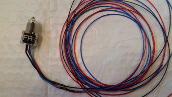
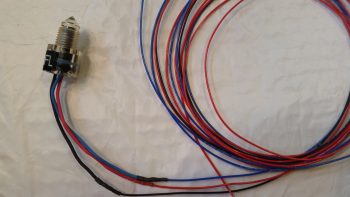
After all the excitement with the ram air inlet, expansion chamber and transition piece, I decided to do something more my speed: heat shrink!  I finally got around to cutting the heat shrink tubing for the left & right sump tanks low fuel level sensor wires and heat shrunk them in place.

In my short term quest to finalize the GIB area components install, tomorrow my main effort will be to get the left GIB armrest forward bracket mold made up so I can glass it up.  Over the next few days I want to get the left GIB armrest bracket completed and have a good amount of the oil heat & fresh air ducting figured out & built.