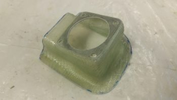
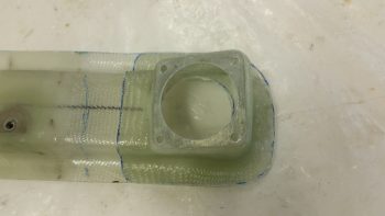
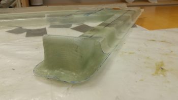
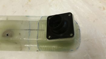
Chapter 22 – Duct Valves

As far as building, today was one of those kluge days from hell….

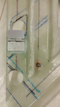
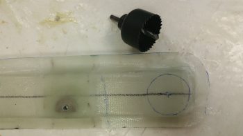
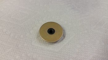
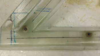
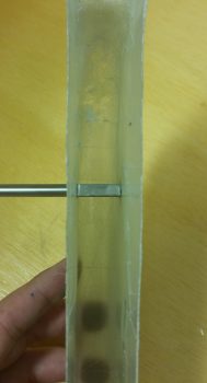
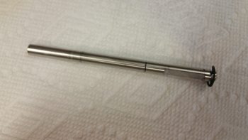
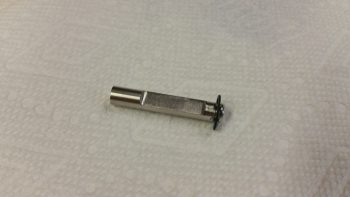
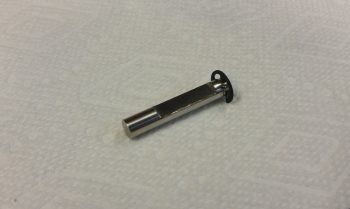
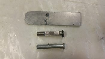
I’m still not feeling 100%… it’s really hot here… and unexpected mishaps have reared their ugly heads again: specifically, on the heat exchanger upper inlet duct heat restrictor butterfly valve.  As you can see below, I have the butterfly valve on top with the 2 drilled holes (I finished the 2nd one tonight), then the first stainless steel rod which proved virtually impossible to drill, then at the bottom the converted drift pin that I handily snapped off the 4-40 tap in the second and last hole . . . After repeated attempts to remove the snapped off tap piece, including knocking it out from the opposite side with a hammer, I was left with only a bent, misaligned butterly valve rod.

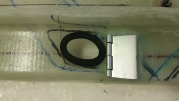
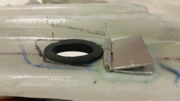
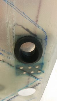
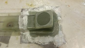
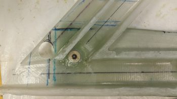
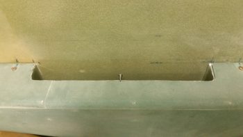
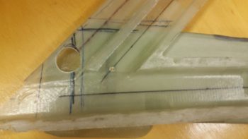
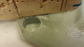
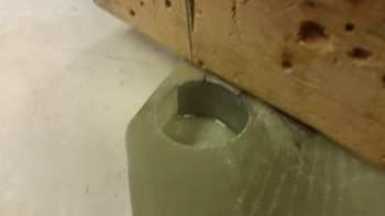
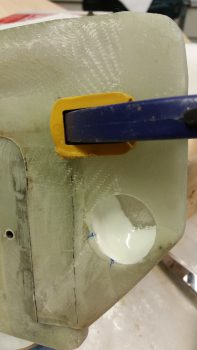
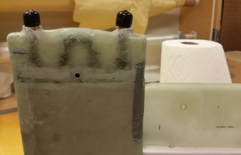
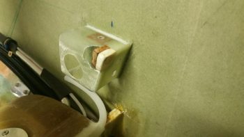
So I digressed and did a fair amount of research on different components and upcoming build tasks.  I then went out and picked up another 4-40 tap set and a couple of large grommets.  Upon returning home, I tested out a grommet in the fresh-cool/heat air transfer vent hole.  Amazingly, in light of the total SNAFU with tapping the butterfly valve rod above, the grommet fit in the odd shaped hole perfectly!

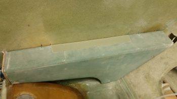
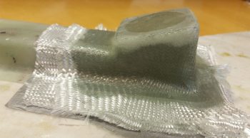
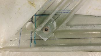
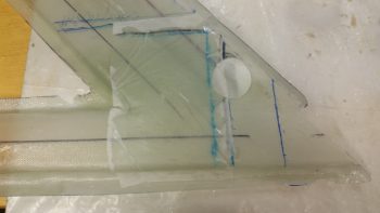
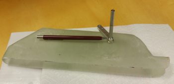
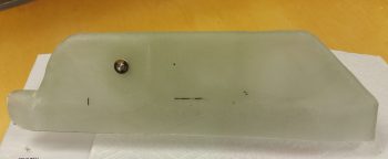
Below is another shot of the grommet more from the side.  You may note that I cut the grommet to taper down towards the top side (left in pic) and then sanded it to smooth it out flat.

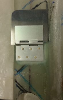
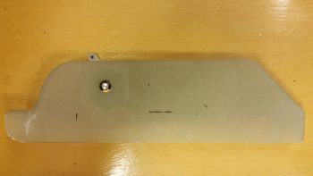
I then drew up a cardboard template for the actual fresh-cool/heat air valve plate and then transferred that over to a piece of 1/16″ 2024 aluminum, which I then cut out.  The valve plate is curved on the top left corner to seal asl best possible with the PIC seat back corner.  It’s also curved on the lower right corner to seal up that curved corner as well.

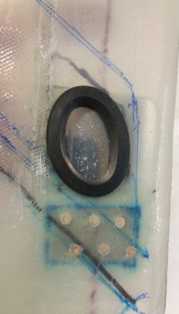
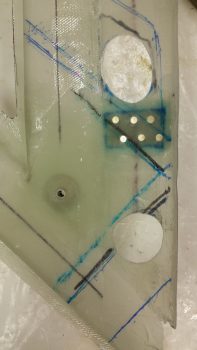
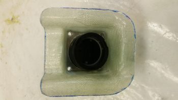
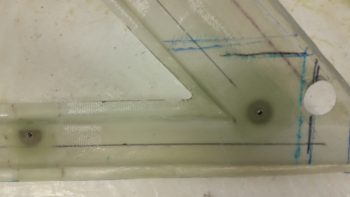
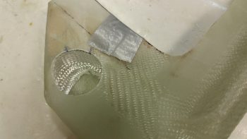
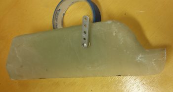
Here is the fresh-cool/heat air valve plate and the rubber vent hole grommet from the opposite (inboard) side.  In the center of the valve plate showing here is where the valve actuation control arm will get mounted.  This will be the control arm that when the lever is moved forward or aft at the pilot’s station, the fresh-cool/heat air valve will be opened or closed for either cockpit cool ventilation air or cockpit heat.

Tomorrow I’ll try to regroup and get much more accomplished, including version 3 of the upper inlet duct heat restrictor butterfly valve rod.

Chapter 22 – Low vent mounting

I started out today by buying and then swapping out the GIB lower eyeball vent mounting screws to stainless steel hex buttonhead screws.  The other ones worked fine, but they were just too industrial looking for my taste,  Yes, minor point, but might as well make it all look nice, eh?

Here’s the another inside shot of the GIB lower eyeball vent mounting screws.

After sanding down and prepping all the mating surfaces, I then whipped up some wet flox and floxed in place the GIB lower eyeball vent & base to the lower horizontal duct.

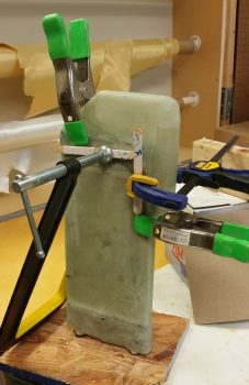
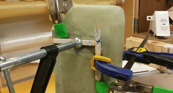
About 8 hours later I pulled off the clamp and cleaned up the minor bit of flox that had oozed out.

The flox spread was nice and uniform, meaning this GIB lower eyeball vent mounting to the lower duct was a success.

Tomorrow will pretty much be a non-build day, but I’ll be back at working on the vent system and oil heat system on Monday.


Chapter 22 – Ducting

I started off today by figuring out where my heat exchanger air will enter from the main air duct into the upper heat exchanger duct . . . which of course is the inlet duct for the heat exchanger.  After figuring out where my perimeter “no-go” areas were for both the main air duct and the underlying upper/inlet duct [as it’s positioned in this pic…look upper left] I marked off the inlet hole.

I then drilled the center mass of the marked hole out with a 1-1/4″ hole saw bit.

I then used a sanding drum on my drill to shape the rest of the hole.  This inlet hole is a fair bit larger than the rest of my standard sized 1.5″ duct area since with the height of the duct at only 0.75″ tall, the air inlet ramp created by the opened valve –to divert the incoming air into the heat exchanger– will be longer and flatter, requiring a bit more open hole area for the equivalent amount of air to flow through.

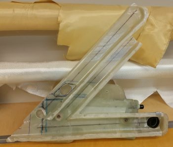
Here’s a shot of my current left side wall mounted GIB area ductwork, with the heat exchanger and the GIB low eyeball vent mounted as well.  If you look closely, you may note that I chopped off 0.4″ of the aft end of the horizontal duct (bottom right of pic), and moved the hole forward 0.4″ to allow moving the low eyeball vent forward for clearance with the 2 oil lines.

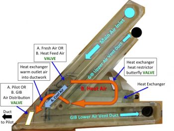
Also, for a bit better understanding of what I’m doing here, I took the pic above and turned it into a quick labeled diagram of all the major parts of the ductwork & oil heat system located in the GIB compartment.  Yes, it’s not the best graphic…. and not to sound overly snarky, but my goal is to get this airplane finished, not to build stunningly beautiful charts!

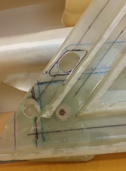
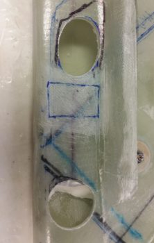
Below is a closeup shot of the 2 heat exchanger-related holes in the main air inlet duct. The top one is the one I just created, and again which allows the outside ram air to flow through the main inlet duct and into the heat exchanger –WHEN THE HEAT AIR VALVE IS OPENED.  Otherwise, if the valve is closed the air simply passes over the valve and continues on its merry way into the ductwork both in the GIB area and forward to the pilot’s seat area.

The lower opening is strictly used only when the air is flowing through the heat exchanger and is the inlet for warm air to flow from the heat exchanger into the ductwork system.  An important note is that the valve that diverts the air to the heat exchanger lies in-between these 2 openings.  Thus, when the valve is open and the air is flowing into the upper opening, it stops any air (or the vast majority of it) from passing into both the rest of the ductwork system (since it’s being diverted into the heat exchanger) or into the lower opening (which will have warm air exiting out of it from the heat exchanger into the ductwork).

You might be wondering about the lower air opening when the heat exchanger is not being used for heat, or stated another way, is not in the “on” state.

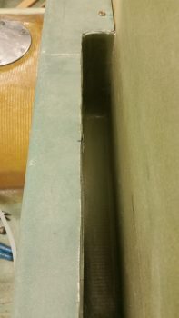
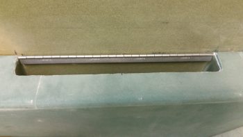
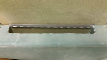
Well, some air will certainly flow into the heat exchanger in the opposite direction through this lower hole.  First, the hole in the main air inlet duct (on the left side) will be covered by the valve plate so no air can flow backwards into the main air duct from the heat exchanger.  Then, if you look below you’ll see a bright shiny lever on the side of the heat exchanger’s upper duct, which is the inlet air duct from the upper hole to the heat exchanger.  This lever controls the heat restrictor butterfly valve.  When the heat exchanger is not being employed to produce heat, this valve is closed, and thus also restricts any air from passing in the reverse direction through the heat exchanger.

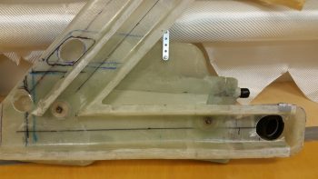
Here’s a shot of what the GIB is more likely to see sitting in the back seat.  This is a good shot of how the heat exchanger will look in its final constructed state.  I just floxed the lower outlet duct (on the right) onto the heat exchanger.  Once I finish constructing the butterfly valve (I just ordered a 1/4″ 2024 rod from ACS) I will also flox the upper inlet duct into place atop the heat exchanger.  On the left side of the pic you can of course see the GIB lower eyeball air vent.

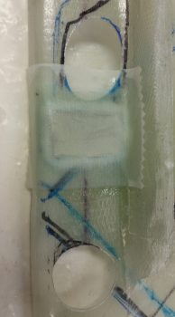
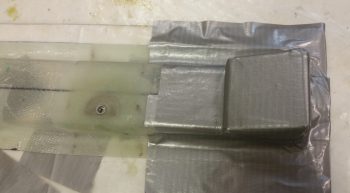
I then started work on prepping the main air duct glass for mounting the Fresh Cool Air OR Heat Feed Air Valve into place (I’m going to have to come up with a standard name for these valves!).  I sanded the interior duct glass where yet another 0.5mm aluminum reinforcement plate will be glassed in for mounting the valve assembly.

I cut out the 0.5mm piece of aluminum (from my German consumables stock!) for my reinforcement plate and then wet floxed it into place with one ply of BID over it.

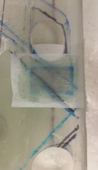
Although I had made up a minuscule amount of epoxy for the layup above, I still had a decent bit left over.  So I quickly moved onto my next layup –earlier than I had planned– and laid up 1 ply of BID on the opposite side of the aluminum reinforcement plate, this ply of BID also glassed in place merely for reinforcement purposes.

I then started working on the G10 Garolite lid for the right GIB armrest storage pocket. After I trimmed and sanded it for a bit, I was able to set it in place on the very slight lip that I created on the inside edge of the armrest storage pocket cutout.

By this point my glass had cured on the valve mounting reinforcement layups, so I pulled the peel ply and cleaned them up.  I then spaced out & drilled 6 holes for countersunk rivets through the lower valve assembly plate and duct wall.  I then floxed the lower valve assembly plate into place and riveted the 6 rivets into place.

Tomorrow I’ll continue my quest to finish the air ductwork and heating system, as well as get as much installed in the GIB area as possible before 1 August.


Chapter 22 – GIB Low Air Vent

My goal today was to get the GIB low air eyeball vent base glassed up, which I’m happy to report I was able to accomplish.

I started out today by marking the aft end of the horizontal duct (which is upside down in the pic below, and subsequent pics . . . just think of it as how you would you view it when looking into the GIB area from the left side of the plane down) with a 1-3/4″ diameter circle to drill it out with the same diameter hole saw.

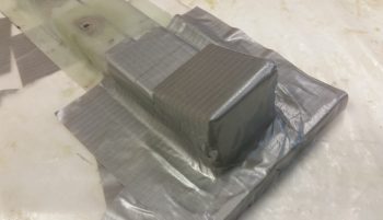
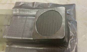
I forgot to take a pic of the hole after I drilled it out, but it came out fine.  I then measured out, cut and shaped a piece of urethane foam for the base of the eyeball vent.  I then taped up the foam and surrounding duct to create a form for the lower GIB eyeball vent base.  As you can see, the base is angled towards the front of the plane in order to warm up the feet area of the GIB.

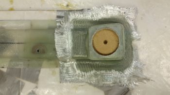
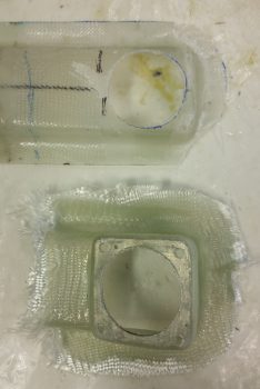
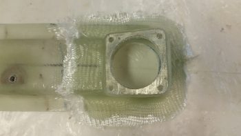
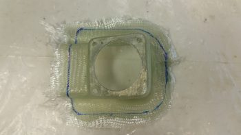
I then drilled a 1-3/4″ hole in my German 0.5mm aluminum sheet and then cut out a 2.1″ x 2.1″ piece centered on the hole.  This aluminum piece will serve as reinforcement for the eyeball vent assembly.  I then sanded the aluminum reinforcement piece to texture it for a better grip with the epoxy & flox.

I then laid up 1 ply of BID over the taped form before wet-floxing on the aluminum reinforcement piece.  I then laid up 2 more plies of BID over the aluminum reinforcement piece and the first ply of BID.

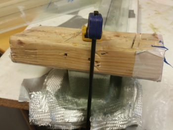
This was a bit of a complex layup with all the angles, so to keep the top flat I weighed it down with a taped 2×4, and then lightly clamped that in place as well.

I worked on the heat exchanger top duct butterfly valve plate that I cut out of 2024 aluminum (sorry, no pics) and after a bit of filing it down I finally got it to fit in both the upper inlet duct & the notched flat on the 1/4″ butterfly valve rod.  However, when I went to drill the holes through both the butterfly valve plate and the rod, I realized after about a half hour of drilling into the rod that my stainless steel bit was not, in fact, working well.

By the time I got done unsuccessfully messing around with drilling the butterfly valve rod, the glassed eyeball vent base was cured.  I pulled the weighted board off the top.

And then redrilled the 1-3/4″ hole for the eyeball vent.

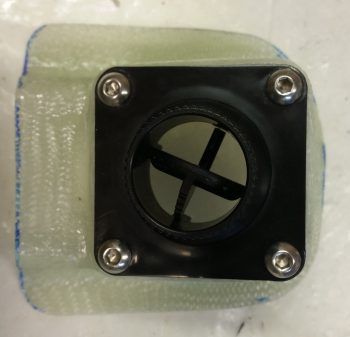
I then set the eyeball vent in place in the freshly glassed base.

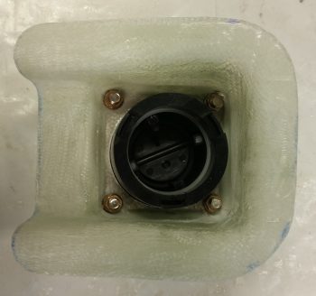
As you can see below, I used the eyeball vent assembly as a guide to drill out the 4 corner mounting holes into the glass and reinforcement layer of aluminum on the vent base.  I then cleaned out the foam inside that made up the form and gave the cured layup a quick trim.

And then pulled the eyeball vent base off of the end of the horizontal duct.

I then quickly checked the fit by placing it back on the duct without the tape.  It fit fine.

I also marked the raw eyeball vent base for trimming.

And trimmed ‘er up with the Fein saw.  I then set the vent base back on the duct.

Here’s another shot of the vent base placed onto the duct.

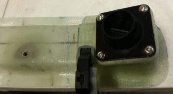
I then mocked up the eyeball vent.

Here’s a shot showing the interior clearance with the eyeball vent in place.

I mounted the eyeball vent into place in the vent base using 4 screws & nuts.

I then mocked up the eyeball vent & base along with the heat exchanger mounted to the duct network.  As you can see, I also terminated the fittings for the oil line hoses that run from the left front wall thigh support fuel sump bulkhead to the heat exchanger.

Here’s a closer shot of the GIB lower vent that I just glassed & configured tonight with the heat exchanger and oil lines in place.  I will assess, and most likely move, the eyeball vent (and base) about 1/4″ to 1/2″ forward towards the heat exchanger for better clearance with the oil lines.

In addition, the actual lengths of oil line hose used was about 4″ and 4.5″ for the respective hoses.  In other words, not much as far as the thinner 3/8″ lines go.

Tomorrow I’ll continue working on the oil heat system and fresh air ductworks, as well as my push to get the GIB area tasks completed before moving forward in prep for finishing the nose.


Chapter 22 – Oil heat ducts

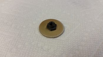
First off, I thought I would show you a couple good shots of the EZ Point Locking Nut that I’m using to attach the heat exchanger to the duct network along the lower horizontal duct.

Today I started off by sanding the interior surface of the glass at the entrance to the GIB high air duct in prep for attaching the forward EZ Point nut that will be used in concert with the aft EZ Point nut to secure the heat exchanger to the duct network.  I then floxed in and glassed over the forward EZ Point nut with 1 ply of BID.

I then peel plied the forward EZ Nut Point 1-ply BID layup.

I had to run up north to help some friends that are moving out of the area here in a couple of weeks.  When I returned back home I pulled the peel ply off the forward EZ Point nut layup and cleaned it up.  Here’s a shot of both installed/glassed-in EZ Point nuts along the lower side of the duct network for mounting the heat exchanger.

Here’s the same shot from the inside of the duct network.

I then did some final preps for floxing the lower outlet duct onto the heat exchanger to meld these two components together permanently.

I then whipped up some flox and floxed the lower outlet duct onto the heat exchanger.  I then clamped the lower outlet duct into place on the heat exchanger.

Here’s a closer shot.

I then headed up north again to help out my friends, and upon my return I removed the clamps and cleaned up the seam of the floxed-on lower outlet duct.

Tomorrow should be a big build day and I plan on continuing my efforts on the oil heat system & ductwork.


Chapter 16/22 – More GIB Stuff!

First off, let’s revisit the phases I identified a while back for finishing up the oil heat & fresh air system.  Here’s the current status of those phases using stoplight colors:

  • Phase I – Ductwork glassed
  • Phase II – Heat exchanger glassed
  • Phase III – Ductwork interface holes drilled and valves built
  • Phase IV – Ductwork installed with heat exchanger and valves in place
  • Phase V – Oil pump installed & oil lines run
  • Phase VI – Pilot seat area ductwork constructed and installed
  • Phase VII – Instrument panel forward ductwork constructed and installed
  • Phase VIII – Valve cables terminated and handles installed

I started out today by pulling the peel ply and cleaned up the 2-ply BID reinforcement layup on the lower horizontal duct for the aft mounting bolt of the heat exchanger.

I then prepped the inside of the horizontal duct for floxing in an EZ Point nut by sanding the area right around the mounting hole.

I then floxed and glassed an EZ Point nut into place and then peel plied the layup.

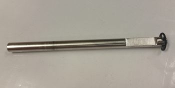
I then pulled out the Dremel Tool and widened the notched flat on the 1/4″ heat restrictor butterfly valve rod.

I also trimmed the edges of the GIB charger mounting flange immediately adjacent to the riveted nutplates.

Here’s a closer look at the trimmed flange on the GIB charger mounting flange.

I then cleaned up the layup on the right armrest midpoint hardpoint.  I then set the countersunk screw in place so that it would be visible by the camera.

I then installed the screw completely to show the screw’s low profile.  If you’re wondering where the screw is located, look at the small mark at about the midpoint of the edge of the storage pocket.

I then took about 15 minutes to mark and cut the right armrest storage pocket lid hinge.  I then mocked it up in place by taping the hinge to the fuselage sidewall.

After the EZ Point nut layup cured, I cleaned up the layup and then mounted the heat exchanger at its aft mounting hole onto the EZ Point hardpoint.

With the aft mounting bolt in place, I was then able to locate the forward heat exchanger mounting hole position.

I marked the position of the forward mounting bolt and then removed both the heat exchanger and the underlying ductwork.  I then drilled the forward mounting bolt hole and remounted the heat exchanger back onto the ducts.

I then ensured the lower duct on the heat exchanger was positioned correctly to further allow me to mark the transition hole that allows the warm air to flow from the heat exchanger’s lower duct back into the duct network.

I then drilled & shaped the duct air transition hole.

Here’s a closer shot of the air transition hole from the heat exchanger’s lower duct into the duct network

I then prepped the glass around the forward heat exchanger mounting hole on the ductwork assembly and laid up 2 plies of BID to reinforce the duct network when the heat exchanger is mounted to the face of it.

I then assessed the airflow through the heat exchanger lower duct (outlet) and decided to glass a dam in the top side of it where the air transition hole mates up to the ductwork network to keep the air from getting trapped in the top corner above the transition hole.

I used a taped piece of foam as the form for the dam and laid up 1 ply of BID for the dam wall.

I laid up the glass a tad wet primarily since the form and glass wasn’t solidly in place, and since I covered it with a more refined micro “ramp” shown below.

Here’s the ramp that I micro’d in place in the heat exchanger lower duct (outlet).  I waited until the layup above was tacky, whipped up some micro and then formed the micro ramp.

I then set my sights on the heat restrictor (butterfly) valve by marking the valve rod for cutting.

I then cut the 1/4″ butterfly valve rod to length.

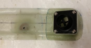
I then test fitted the cut 1/4″ butterfly valve rod with the valve lever in place as well.  The pic below shows the outboard side of the heat exchanger’s upper (inlet) duct.

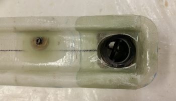
And here’s a shot of the inboard side of the heat exchanger’s upper (inlet) duct.

Tomorrow will be a very light build day since I’m helping my friends that are moving here in the next couple of weeks.


Chapter 22/24 – GIB STUFF!

First off, I’d like to convey my latest task sequence plan for the build.  My immediate goal is to finish up the GIB area components since those will be the hardest to work after the strakes are installed.  I’m giving myself up until 1 August to finish up these GIB seat area, pilot seat area, and nose component installs and then move on to building and glassing the top of the nose.  Then I’ll move onto constructing the canopy.

As for today, I started off by prepping the left GIB armrest forward mounting bracket for getting floxed to the left fuselage sidewall.
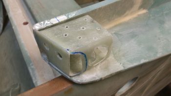
After mounting the forward mounting bracket to the left GIB armrest with its attach bolt, I then mixed up some flox and slathered it onto the outboard side of the mounting bracket.
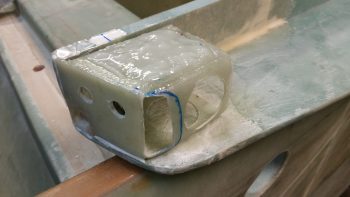
I then mounted the left GIB armrest into place, installing the 4 aft bolts into place to hold the freshly floxed armrest forward mounting bracket firmly against the fuselage sidewall.
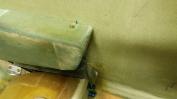
I used the same epoxy that I used above to layup a ply of BID to seal the cut angled edge of the heat exchanger lower duct piece.  This edge was one that I had to cut to remove the duct piece off to the heat exchanger cover.  I then peel plied it.
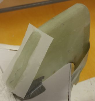
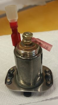
While the epoxy above cured I digressed a bit to knock out a small task that while not needing accomplished just now, curiosity got the best of me.  I drilled and riveted 2 nutplates to the GIB cigarette lighter charger that will be used in mounting it later on.
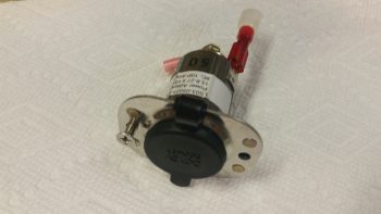
Here’s a shot of the backside of the riveted nutplates.
In addition, I also mounted the two 1/2″ oil heat lines that terminate into the reducers mounted into the left side bulkhead that is an extension of the GIB thigh support fuel sump front wall (no pics).  There’s not a lot of space to get in there to mount the oil line fittings, so it took a bit of time to get them installed.  I still plan on making a specialized wrench that will better allow me to install & remove these 1/2″ oil lines due to this limited space.

By the time I finished riveting the nutplates onto the GIB charger & installing the oil lines, the layup on the heat exchanger lower duct piece was cured enough that I pulled the peel ply & cleaned it up.  I then “mounted” it on the heat exchanger, positioned it in place where it will be mounted in the cockpit, and then drilled a hole through the aft heat exchanger mounting hole into the lower horizontal duct that sits immediately behind (outboard) of the heat exchanger.

I then removed the ductwork and sanded down a 2″ wide swath from the top edge of the lower duct flange to the bottom flange edge, with the mounting hole in the center (1″ mark) of the sanded swath.
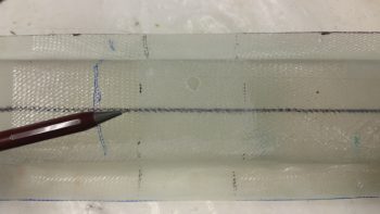
Here’s a wider angle shot.
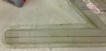
I then laid up a 2″ wide ply of BID from the top edge of the horizontal duct flange to the bottom flange edge for reinforcement when the heat exchanger is mounted.  For a little extra strength, I also laid up a second ply of BID 1.5″ wide that terminated on the bottom and top edge of the actual duct (not the flanges).  I then peel plied the layup.
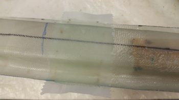
I had also cut out a 0.5mm piece of aluminum (from my German stock) to use as a hardpoint for the midpoint attachment of the right side storage pocket to the right GIB armrest.  This setup is simply to reinforce the midpoint glass so that it won’t crack under the pressure of the countersunk screw that will be mounted.

I then floxed the aluminum piece in place and covered it with 1 ply of BID using the epoxy that I had made for the layup above.  I then peel plied this layup as well.
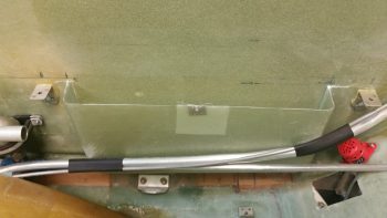
I then removed the left GIB armrest to reveal the forward mounting bracket, which of course also serves as the GIB headset jack plate and PTT button mount.  I had just a bit of flox leftover from the previous layups, so I used that to seal the perimeter of the flox on the bracket.
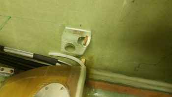
Here are a couple more shots of the left GIB armrest forward mounting bracket floxed in place.
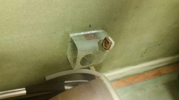
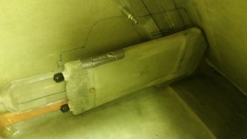
Here’s a pic of not only the left GIB armrest forward mounting bracket floxed in place, but also the two 1/2″ oil heat lines that I mounted earlier.
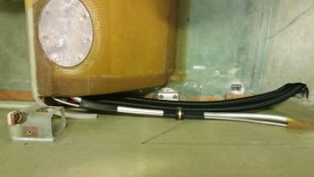
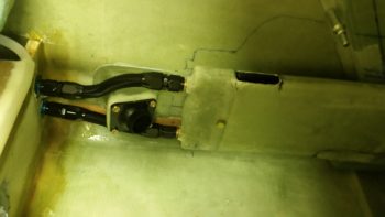
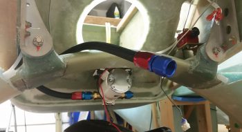
Here’s a shot of the oil feed line that I previously mounted that comes out of the oil pump and to the heat exchanger via the 1/2″ to 3/8″ reducer.  In the foreground you can see the oil return line that comes from the heat exchanger back to the engine oil sump.  I terminated this oil return line hose with the AN-8 fitting just prior to taking this pic.
My final task of the evening was working on the heat exchanger upper inlet duct’s restrictor (butterfly) valve.  I started off by redrilling the valve mounting holes that I had covered up with the reinforcement plies of BID, then inserting the valve plate’s mounting rod into the duct holes and marking the sidewall positions onto the rod.
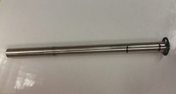
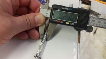
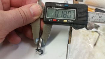
I then Dremeled and filed a flat spot almost 1/16″ (0.060″) deep into the valve plate’s mounting rod specifically to mount the valve plate to.
The diameter of the valve rod is 0.240″.
And as you can see, the width of the rod after I cut nearly 1/16″ of it out, is 0.180″.  Makes sense eh?
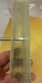
Here is the valve rod installed in the duct with the valve plate mounting flat showing.  As you can see, I need to make the flat a little wider so that the edges of the valve plate sit flush with the duct sidewalls.
I’ve left the heat restrictor valve rod long for now, but will be cutting it to length in the next day or two after I’ve worked out & finalized all the other working valve dimensions.  It will most likely get cut at the spot where the tip of the pencil is pointing to.

The side shown below is the outboard side, so as I mentioned before the valve lever will operate “behind” the heat exchanger and away from any body parts of the delicate GIBs! ha!
Here’s the inboard side of the heat exchanger, with the restraining E-clip showing on the inboard end of the heat restrictor valve rod.
Tomorrow I will continue to work all the GIB area component installs, including working to finalize all the stuff I worked on today.


Chapter 22 – Heat Exchanger Wrap-up

Wrap-up as far as sealing up the heat exchanger . . .

I spent about 45 min pulling the peel ply from both the aft end layups of the heat exchanger and side reinforcement ply of BID layups on the upper/inlet duct.

And on cleaning up the peel ply strings and the edges of each layup on both sets of layups.

The heat exchanger needs a good sanding to smooth out all these mini-layups, but beyond that I’m done with the mechanical resealing of the heat exchanger.  Tomorrow I’ll jump back in to get a lot more work done.  In fact, I need this week to be a very productive one to get all these ancillary (read: non-airframe) components completed and off the to-do list.


Chapter 22 – Heat Exchanger Valves

This past week hasn’t allowed for a lot of major build efforts, and I expect that won’t change until starting on Monday.  I have some good friends that are moving out of the area so I’ll be spending a bit more time with them over the next couple of weeks.
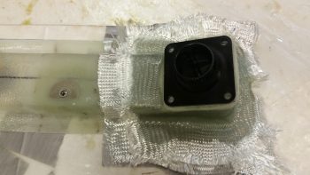
Today I started out by sorting through & figuring out LED lights for the GIB area floor area lights that will be located in the fuel sump tanks’ low fuel warning sensors covers.  After figuring out the LEDs, I then updated my cockpit lighting wiring diagram.

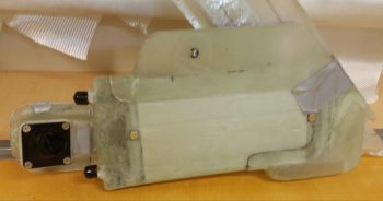
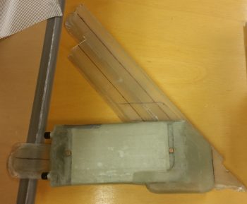
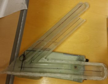
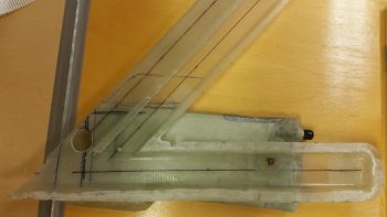
I then mocked up the upper & lower heat exchanger ducts after my design, placement, and initial construction of the heat restrictor valve (butterfly style) that resides towards the aft end of the heat exchanger inlet duct.

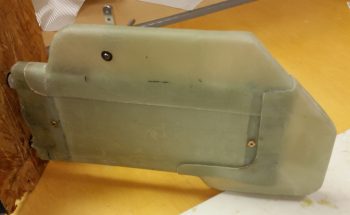
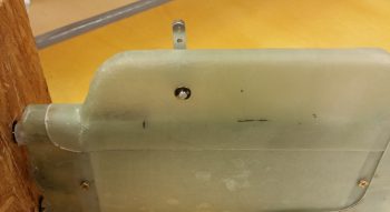
I would have preferred to have the heat restrictor valve located about 1-1/2″ forward, where you may be able to see a location dot.  However, since I wanted the valve’s actuator arm on the outboard side of the heat exchanger unit for clearance to keep it from hitting the GIB’s knee or leg when the valve is actuated, I had to place it a bit aft of where I wanted (where it is in the pic below) to allow for valve actuator arm clearance with the underlying (outboard, on the cockpit wall) ductwork.

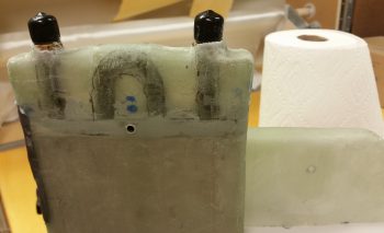
I then laid up 4 more small pieces of BID on the aft side of the heat exchanger to finalize the sealing up of the heat exchanger cover.  In addition, I added a 1-ply BID “patch” on each side of the heat exchanger upper inlet duct around the heat restrictor valve mounting holes (seen on the right side in the pic below).

Tomorrow will be another light to non-build day.  Again, however, I plan to be back at it hot ‘n heavy on Monday.
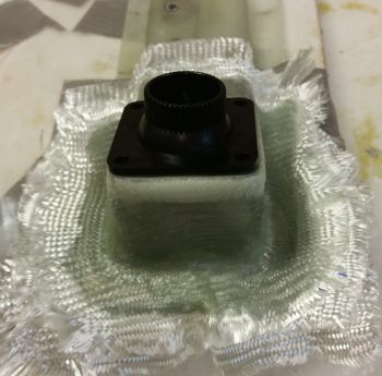
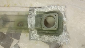
Chapter 22 – Resealing heat exchanger

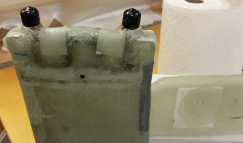
Today I glassed round 2 of securing the halves of the heat exchanger back together.  I started by simply filling in the 2″ gaps created by the duct tape that I used to hold the 2 sides together tightly.  Again, I used 1 ply of BID as I did before.
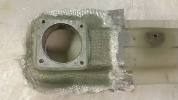
I then glassed a small patch of BID on each forward corner (top side in pics below).

Finally, for this round I went to the aft side and laid up a small 1-ply BID patch just outside of the AN fitting posts on the corners (bottom in pics below).

I then peel plied all these small layups.

Later in the evening I pulled peel ply from the layups and cleaned up the layups.

I have 1 more round of layups to finish up the closure of the heat exchanger, which I’ll work on tomorrow.