Chapter 9 – Parking Brake cable install

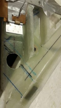
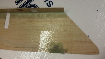
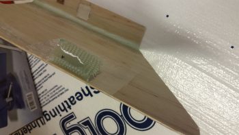
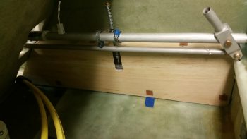
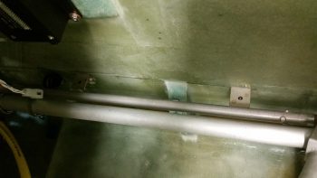
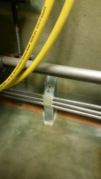
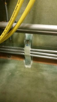
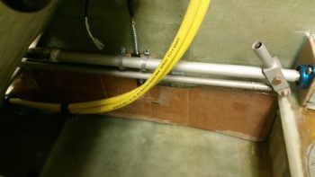
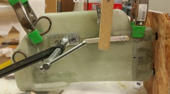
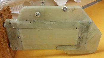
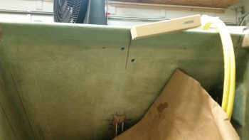
Today, before I headed off to my neighbor’s Labor Day cookout, I 5-min glued the next forward section –about 5 inches– of the Matco parking brake valve control cable conduit to the bottom corner edge and side of the left NG30 plate.

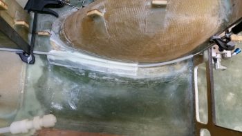
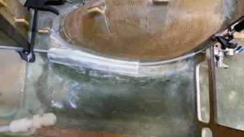
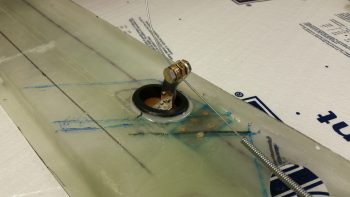
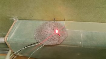
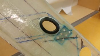
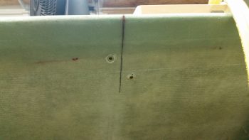
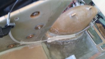
I made up some micro and applied it around the Nylaflow cable conduit, and then laid up a prepregged 1.5″ x 4.5″ ply of BID over the top of that segment of Nylafow cable conduit. As with the previous layup, I peel plied both the top and bottom edges of the layup (sorry for the slightly blurry pic…)

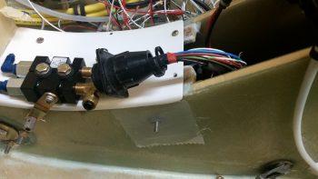
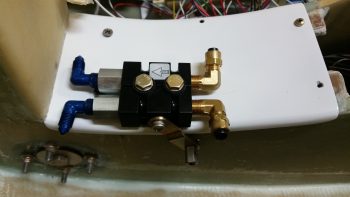
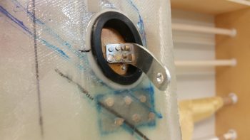
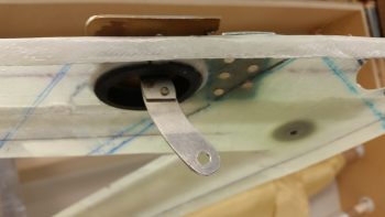
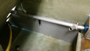
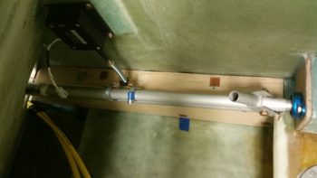
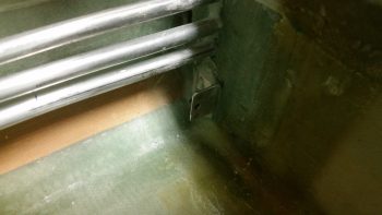
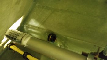
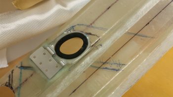
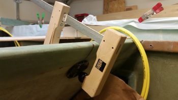
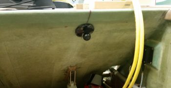
Here’s a shot showing the proximity of the conduit layup that I just did to the Matco parking brake valve.  Also note that the position of the cable conduit that I just attached to the NG30 plate is the first half of what will essentially be an “S” curve in the conduit.

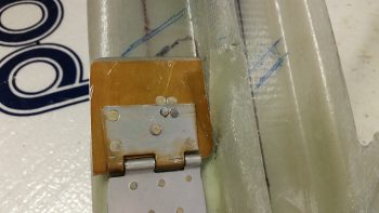
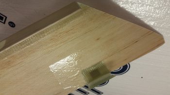
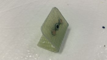
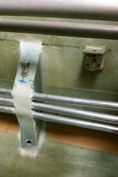
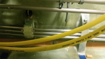
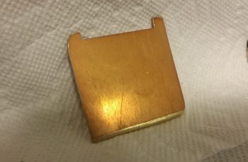
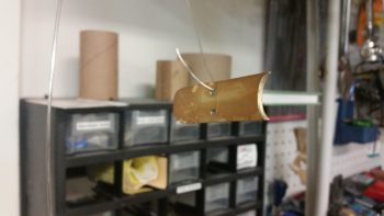
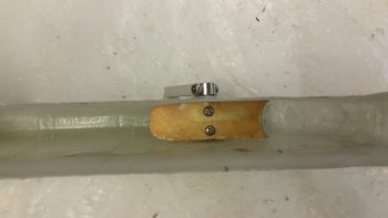
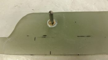
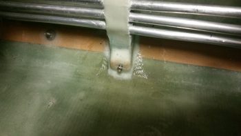
About 10 hours later, after the cookout, I got back in the shop to remove the peel ply off the layup, and clean it up a bit.  I then confirmed where the parking brake control cable (the actual cable, not the cable conduit) Adel clamp location was required. I then attached a Clickbond hard point for the Adel clamp with 5-min glue, by using the whole assembly mocked up on the cable (not shown).

I then added a scant bit of flox around the edges of the Clickbond for transition, and then laid up 2 plies of BID over the Clickbond.  I then peel plied the layup.

I needed to get the Adel clamp mounting Clickbond mounted and glassed since the next attaching of the cable conduit will overlap the 2-ply BID layup securing the Clickbond in place.  Attaching the Clickbond last, after the cable conduit was attached, would have been much more difficult.

Tomorrow I’ll finalize this phase of the Parking Brake control cable conduit install. I also plan on starting back on the oil heat ductwork and GIB area.


Chapter 9/22 – Micro Layups

Yes, it finally happened guys!  I’m back in the shop.  I have to tell you after being out of it for a couple weeks I had to get my sea legs back as I was suffering a little bit of analysis paralysis on what to start in on first.  Luckily I had made my task list up the other morning so I just grabbed it and started at task #1.  That saved me from spinning my wheels and wasting time.

I started off with a bunch of small layups, thus the title of this blog post.  First off, I sealed off the significant gap between the fresh air/heater air valve (Valve #1) plate and the duct sidewall.  I taped off the valve plate with brown packing tape (I’m out of clear) and kept the valve plate up flush to what will be the back wall of the duct by taping it to a 12″ ruler that I laid across the other duct back wall edges as well.

I then added some flox along the edge of the taped up valve plate and added a ply of BID. I then peel plied it.

Since I used fast hardener in my epoxy, here’s a shot a few hours later when I pulled all the tape and cleaned it up.  The top pic shows the valve in its normal closed state (fresh air through the ducts) while the bottom pic shows the valve open and the side edge seal at work (diverted air to heat exchanger).

When I created the valve plate edge seal above, I also laid up a ply of glass on the inside of the bottom horizontal duct edge and peel plied it.  In addition, I cut a small rectangular reinforcement piece of 0.5mm aluminum and floxed in place on the outside bottom edge of the duct and covered it with 1 ply of BID.  This too got peel plied.

These layups and aluminum plate will serve to reinforce the installation of the PIC/GIB air distribution valve (valve #3) when I install it.

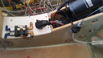
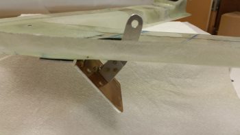
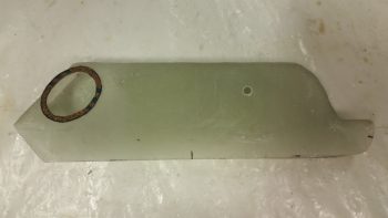
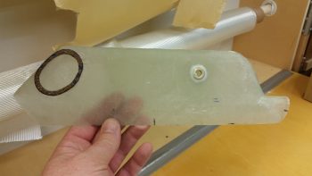
Then, for the first time, I test mounted my Matco parking brake valve on and thru the finished & painted forward NG30 cover plate.  Besides wanting to ensure the valve fit and clearance for the operation of the lever arm, I also needed it in place to determine the length of the parking brake control lever cable to the pull T-handle.

I played around with the control cable length for a while and estimated as closely as I could the final position of the parking brake pull T-handle.  Once I decided on the parking brake T-handle location, I cut the entire cable to length, and then cut the outer cable sheath to expose the last 6″ or so of the control cable wire.

I then cut the 1/4″ Nylaflow control cable conduit and roughed it up with sandpaper.  I also sanded all the contact point areas along the path of the 1/4″ Nylaflow conduit along the left side lower corner of the nose wheel well cover (NB) and along the bottom edge & side of the left NG30 plate.

I then 5-min glued about a 6″ length of the Nylaflow into place along the bottom corner of the nose wheel well cover (NB) and let it cure.  After the 5-min glue cured, I then micro’d around the conduit and laid up a prepregged ply of BID 1.5″ wide x 9″ long.

I then peel plied the edges of the initial parking brake control cable conduit layup.

Since the path of the parking brake control cable conduit will require a sort of an “S” curve on the lower aft area of the left NG30 plate, I decided to secure & glass it in place in smaller, bite-sized sections in order to minimize my chances of any given section pulling free or going haywire as I set each segment in its correct spot.

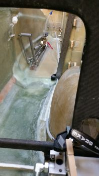
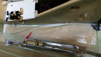
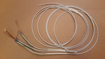
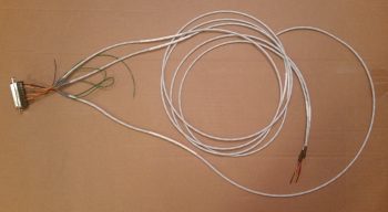
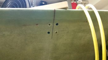
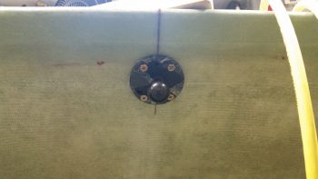
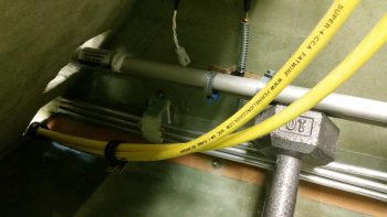
I uploaded the above pics here side-by-side to give you somewhat of a panoramic view of the entire parking brake control cable run from T-handle to parking brake valve.  Again, this is on the list of things needing done before I close up the top of the nose and access to these areas that I’m currently working is greatly restricted.

I have to say that there is often a lot of research, planning and design time spent that I don’t really report on.  After I did all the above, I spent a good half hour assessing and reviewing the placement and configuration of the two pilot seat thigh support ribs. Moreover, I finalized the details on aft side of the pilot thigh support, which unlike most Long-EZs will be modified to incorporate a triangular duct across the aft edge for the right foot heater vent.

Tomorrow my next door neighbor is having a Labor Day cookout. Since I’ll be over at his place for most of the afternoon and evening, it will be yet another light build day.  But I do plan on getting as much done as possible tomorrow on this internal cockpit stuff.


Chapter 22 – Cheat when you can!

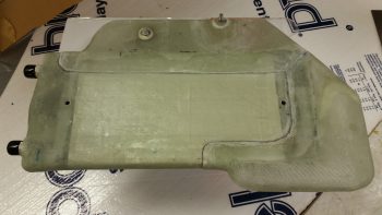
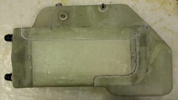
I started out today by cleaning up the inboard face of the heat exchanger by sanding the edges of the added upper & lower ducts where they overlap onto the main assembly.

I then cleaned up & prepped the heat exchanger for glass, or actually for 1 ply of carbon fiber.

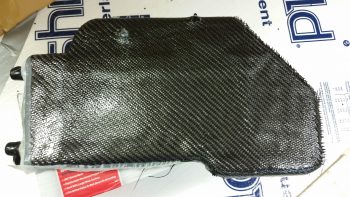
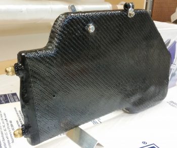
Here’s the ply of carbon fiber after I laid it up and peel plied the edges a bit to ensure it stayed in place.  I didn’t go with the traditional super sexy carbon fiber look, since the reason I’m adding the carbon is I believe that with this heat exchanger being inboard of the ducts, it will get rubbed on with legs, knees, small marsupials, etc. over the years.  If it was painted, as I’ve seen with many a canard, over time the paint would simply rub off.  I wanted something that would not only be a good contrast with the gray granite paint that I’m using for the cabin, but that would be hardy enough that it would withstand getting rubbed on over the years without discoloration or deterioration of the surface.

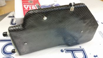
I used fast hardener so a few hours later I trimmed the carbon fiber and got the heat exchanger pretty much back to the way it was before, just with a ply of carbon fiber on the face of it.

I wasn’t sure what I was going to do with the aft end, I just knew I didn’t want to attempt making my layup infinitely more difficult by trying to put carbon fiber here and wrap it around.  Admittedly, my original plan was to get much closer to the edge but the carbon fiber apparently had other thoughts on the matter.

With so much stuff to get done on this plane, I punted and went with the 80% solution to get this thing in the done column, and simply painted the aft end . . . In the grand scheme of things I don’t think anyone will really notice that the aft “face” is painted black.

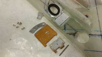
I then got to work on the fresh air/heating air routing valve.  Below is the valve assembly in its component parts, ready for assembly.

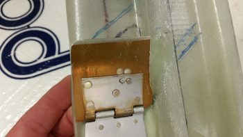
And here’s after I riveted it all together . . . the second time!!  You see, the valve hinge had to go in first before I riveted all the main pieces together.  So of course I went to Tahiti for a few minutes in my mind while I riveted the first couple of rivets to get it all together.  My fault, but what a royal PITA to drill those rivets out.  Plus, it widened the holes a bit so I used a bit longer rivets and merely mashed harder!

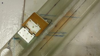
Ok, so she ain’t perfect, but it looks like this dog will hunt.  The one thing I’m not overly happy with is the height of my valve, since it’s taking up valuable space in my duct and reducing the duct’s cross section for airflow by almost 0.5″.

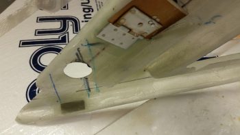
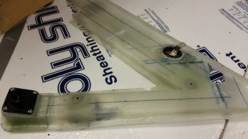
Here’s a shot to see where this valve is in relation to everything else.

And here’s a few shots of the valve and the attached control arm.

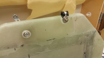
I then added a cable mount bolt and a cable to test out the function of the valve.  It’s simple and I don’t think there should be any issues (besides having to trim down the upper edge of the valve since it’s just a hair wide.)

With my ductwork tasks done for the evening, I focused on getting the cable runs to the GIB headset jack squared away, primarily at the Dynon Intercom harness connector.

After doing over an hour’s worth of research and brushing back up on the intercom wiring, I then cut the wires to length, stripped the wires and then added shield grounding pigtails by using ground solder sleeves.

The pilot and GIB Mic/PTT wires share a common ground at Pin 2, so I went ahead and did a solder wire splice to add a small length of 20 AWG wire to the 2 shielded wire ground wires.  BTW, I used the Bob Nuckolls’ technique for solder splicing 2 wires together.

Here’s my soldered wire splice.

I then added a piece of shrink wrap over the soldered joint.

Here’s a shot of my Dynon Intercom wiring harness . . .  so far!  You can see that I labeled the main cable insulation and terminated the individual wires with the included D-Sub sockets.

Wrapping up the evening, I terminated the sockets into the Dynon Intercom 25-pin D-Sub connector.  I also stripped and heat shrank the GIB headset jack ends (the sides in the left GIB armrest) of the cables in preparation for installation.

Tomorrow I’ll continue to work on knocking out all this extraneous build stuff so I can get on to the nose, canopy and strakes.


Chapter 22 – Kick plate finished!

Today I started out by pulling the GIB kick plate out to check the forward mounting bracket layup.

The mounting bracket looked good with the angle appropriate to how the lower corner of the cockpit is shaped.

I could tell by the bottom of the cured mounting bracket that not all of it was in contact with the taped fuselage corner . . . I guess gravity isn’t what it used to be!

I first drilled the #8 screw mounting hole through the kick plate and part way through the forward lower bracket when it decided to remove itself from the kick plate.  I then drilled and riveted a K1000-8 nutplate to the mounting bracket, and then trimmed all 4 bracket sides with the Fein saw.  Finally, I drilled anchor holes and sanded the bottom of the mount that will get floxed to the fuselage corner.

Here’s a few pics of the completed forward kick plate mounting bracket.

I then remounted the composite forward mounting bracket onto the kick plate.

Knowing that only a small portion of the mounting bracket had been in contact with the cockpit corner when I set it, I slathered it up with flox before remounting the kick plate.  I used fast hardener… so a few hours later after it cured I pulled off the kick plate to find that my mounting bracket floxing endeavor was successful.

While the kick plate mounting bracket flox was curing I took my fuel sump low fuel level sensor covers outside and painted them with the Rustoleum granite paint that I will be using for the interior cabin paint.

While the fuel sump low fuel level sensor covers’ paint was curing I called Mike at ACK to go over my ELT install configuration.  He gave me some very key information that will be very pertinent to my ELT installation.

I then determined the size of the phenolic LED light mounting reinforcement plates, cut them and then 5-min glued them into place (after I removed the paint and sanded the glass where they were mounted inside the covers).

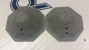
I then determined where the 2 LED holes would be situated, then drilled the holes.  I tested out the angle of the LED light beams, so when I drilled the holes I made them a bit more horizontal in comparison to the aircraft waterline.

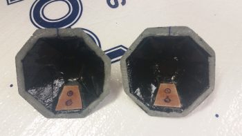
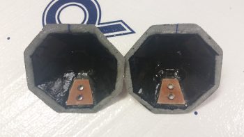
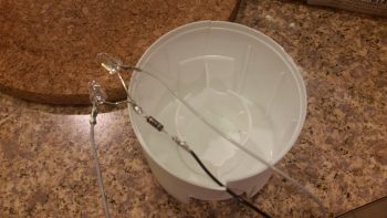
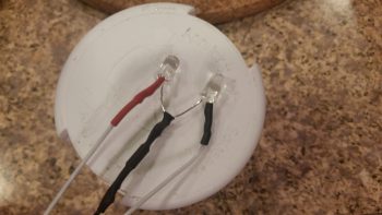
With the LED mounting holes ready, I then prepped the LED lights for mounting by soldering the red & white LEDs and wires, including a 470 Ohm resistor on the shared ground wired.

I then added heat shrink to secure & protect the solder joints.

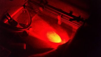
Although the pic below looks like you’re looking down into a fiery volcano, I included this representative shot of the red LED test lighting.

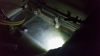
Here’s the white LED test.  Again, the light showing up in these pics is more drastic, contrasting and harsh than what is really viewed in person.

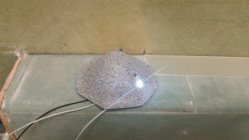
Here are another couple shots of the sump low fuel sensor cover LED floor lights from the front, facing the camera (which I shot at an angle so they wouldn’t “blind” the camera).

Again, this is a representative view of the red & white LED lights glued in place into the right sump low fuel sensor cover.  The left looks pretty much the same of course.

Concurrent to the work I had been doing on the LED floor lights, I also primed & painted the kick plate with my gray cabin granite paint.  Over 4 hours later I hit it with a couple coats of matt clear coat.

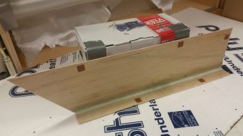
This is about an hour later after the clear coat was dry enough to set the kick plate in place  to get this pic.

Here’s another shot of the painted and clear coated GIB kick plate.  BTW, I checked the weight of the kick plate just prior to painting it and it weighed in at a whopping 5.8 ounces.

Tomorrow I’ll continue my quest to finish all things GIB before moving on with other parts of the build.


Chapter 22 – Play Time is Over!

No more electrical stuff for me… back to the GIB area!  Ok, except this one sideline task. HA!

Today I started by finishing up annotating the J3 PQD connector color codes, which of course meant digging in the GRT Mini-X manual and also seeing what the wire colors were that I physically had on hand.  Since I had the Mini-X wiring harness (15-pin D-Sub) in my hand, I decided to go ahead and knock out the wire harness connector for my Mini-X.

First, I had to pull a few wires for connections that I won’t be using.  These few specific wires came installed on the GRT-provided 15-pin D-Sub connector/harness.  I measured the required wire lengths between the back of the Mini-X and the J3 PQD connector on the Triparagon.  I added a couple of inches for ‘insurance’ purposes and another half inch to account for the multiples pairs that would be twisted together, then ended up cutting all the wires down to 10.5″ long.  I then crimped some D-Sub sockets onto 3 wires for the magnetometer (since it’s optional) and terminated them into the Mini-X D-Sub connector.  I then twisted the appropriate wire pairs together using a small portable drill.
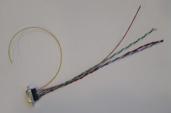
I then terminated the ends of the wires with D-Sub pins on the opposite end from the Mini-X connector and performed a continuity check on each wire… all good.
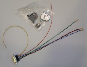
Then, on the Mini-X side of the harness I installed the D-Sub backshell.
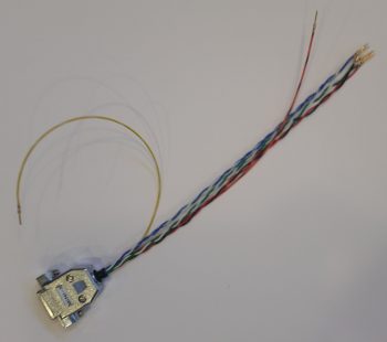
Having also just received some more correct-sized wire labels, I then labeled the 2 individual wires and the 3 wire pairs.

For the panel component labels that run ONLY between the panel components themselves, or the panel components and the PQD connectors, I’m using a bit more simplified wiring label scheme than the one I use for the rest of the plane: essentially providing just a pin number, the wire function such as “power” or “DU link” and an opposite pin number, all separated by dashes.  Obviously, on the panel I’m looking at the wire runs from the back of the given device and seeing its termination point just a scant few inches away… all the info is there for me to see straightway, except the pin #’s and wire functions. So, for example, the lone magnetometer signal wire label goes like this:

10-MAG SIG-9

Pin 10 on the Mini-X EFIS D-Sub connector, the truncated description as to the function of the wire, and Pin 9 on the J3B PQD D-Sub connector.  Short and sweet.  If a twisted pair is getting labeled, I simply add both pins on each side separated by a “/” (aka 11/12).  I’m still sticking with the more robust label scheme throughout the rest of the plane which allows me to determine where the wire is coming & going, what devices it goes to (points A & B) and what pins it connects to at each end (typically power, ground or data signal).
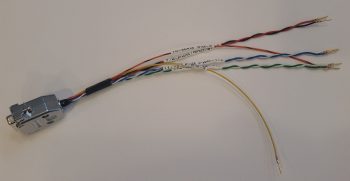
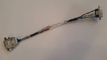
Here’s a shot of the Mini-X wiring harness, minus the D-Sub 15 backshell (which is on order) for the J3B side.
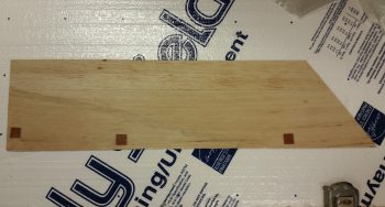
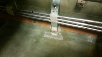
I then set my sights on finalizing the GIB right side kick plate mounting.  I started by stuffing some plastic saran wrap into the aft lower hardpoint screw hole, and then laid up a ply of BID over it.
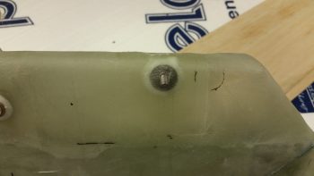
A few hours later it was really close to being cured, so I hand drilled the hole through the glass in the front to remove the plastic.  I then cleaned up around the hard point screw hole and test fitted the screw.
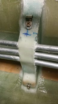
Here’s another wider angle shot of above.
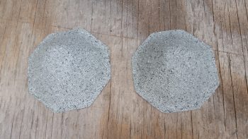
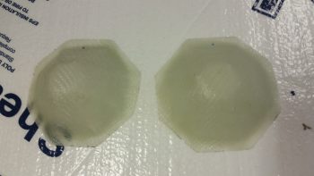
I then spent a bit of time sanding down and cleaning the fuel sump low fuel sensor covers.
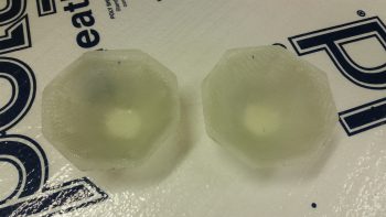
Here’s the exterior side of these things . . .  After sanding, I then gave them a good Simple Green wash and dried them off.
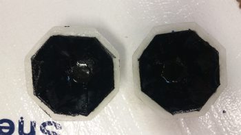
I then taped up the interior edge of both sensor covers and then shot them with a couple quick, light layers of black paint.  I would have preferred to use matt paint, but I only had gloss on hand so they’re a bit fancier than I had intended.
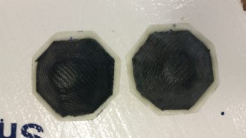
I then prepped both the outboard side fuselage area and of the interior wall of the kick plate with clear packing tape to keep the composite bracket from gumming anything up.
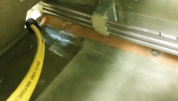
I then set up 2 prepregged 3-ply BID layups.
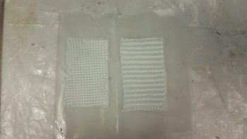
I then wet out the prepregs and combined the 2 stacks of 3 plies to make up a 6-ply forward kick plate mounting bracket.
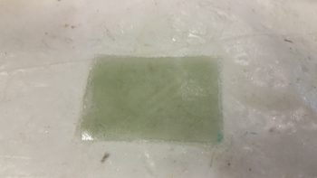
I then laid up the 6-ply bracket layup half way onto the forward kick plate mounting hardpoint.
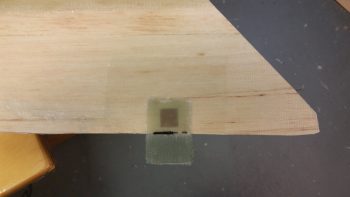
I then folded it back on itself so that it was almost touching.  My goal here was that when the kick plate was mounted, gravity would simply pull the glass down onto the protective tape on the floor, creating the exact correctly shaped bracket blank –since the floor at the corner here is 45°– after it cures.
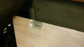
Here’s a shot of the entire kick plate, with the 6-ply mounting bracket glass formed on the inside.  I was able to get just a peak of it through the holes in the front seat bulkhead and from what I could ascertain, my “shot in the dark” layup looks ok.
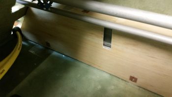
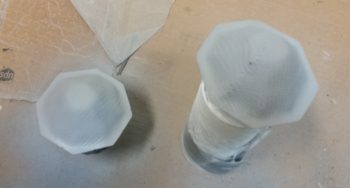
As the kick plate bracket glass cured, I then took a quick opportunity to apply a couple of coats of gray primer onto both thigh support fuel sump low fuel sensor covers.  Since I’ll have a pair of LEDs poking out the bottom of each of these covers, I wanted to get them painted so as to not have to worry as much about taping off those LEDs, which again will be on the bottom side, when I paint the rest of the back seat area.
Tomorrow I’ll continue working on all things GIB!
 

Chapter 24 – Kick plate mounting

Today I started off by finalizing the cleaning up & initial round of micro’ing some divots I had made (during cleanup) and the minor gaps between the wood pieces on the GIB right kick plate.

I then let the micro cure a bit as I cut the BID and peel ply for the layup.  I then laid up the 1 ply of BID using MGS 335 with fast hardener.

I then peel plied the layup.

I then took a break, grabbed something to eat and uploaded my pics to this website.  A bit later the layup was cured so I razor trimmed it, pulled the peel ply, cut the notch for the roll trim spring assembly, and then test fitted the kick plate in place.

It took a few iterations of trimming both the front and the aft edges of the kick plate to allow it to slide into place, but I eventually got it to settle in quite nicely.  Towards the front side top you may notice a square patch where I cut out the interior glass and wood to thin the top out for clearance with the underlying Adel clamp.

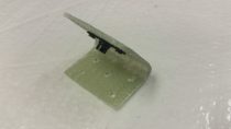
I then made up a brand new 6061 mounting tab for the aft edge and riveted a K1000-8 nutplate to it.  I also riveted K1000-8 nutplates to some existing mounting tabs I had made up earlier for the armrests.  I then added some protective tape around the mounting holes and mounted the brackets with #8 screws.

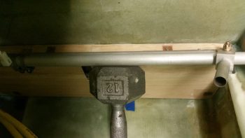
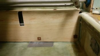
I then whipped up some flox, floxed up the 3 mounting brackets and set the kick plate in place.  To ensure the brackets were pressed into place nicely, I rested a weight against the kick plate.

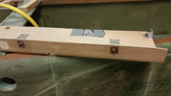
A bit later, after the flox cured, I pulled the kick plate off the installed mounting brackets and cleaned the protective tape off of the kick plate.  Here are the 2 upper mounting brackets floxed in place to the fuselage sidewall.

And here’s the kick plate’s aft mounting bracket floxed in place to the front thigh support sump front wall bulkhead.

Before I pulled off the kick plate I drilled an 11/64″ hole through the bottom aft phenolic hardpoint in the kick plate.  I then widened it out in the fuel line bracket to accept a RivNut hardpoint that I’ll use for this mounting point.

I cut a few grooves into the RivNut to add some gripping power and taped up the end with duct tape.

What’s not seen here (you’ll see it when I remove the kick plate) is the 1/4″ thick Divinycell foam spacer that I floxed into place between the kick plate interior side and the fuel line mounting bracket.  The inboard half of the RivNut is floxed into the foam spacer while the rest of it is floxed into the fuel line mounting bracket.  The spacer itself is floxed on the outboard side to the face of the fuel line mounting bracket.

Later, after the RivNut & foam spacer flox cures, I’ll layup 1 ply of BID around the spacer to secure it and the RivNut to the fuel line mounting bracket.

I then used the same 12-pound weight pressed against the lower RivNut hardpoint (and foam spacer) to keep it securely in place.

After I finished writing the majority of this blog post, I went back down to the shop to catch the flox on the lower kick plate RivNut hardpoint in its “green” stage of curing –where it’s still just a little pliable– and I was able to do so [Incredibly easier when the epoxy/flox/micro is in this stage… it has the consistency of caramel candy and can be cut and removed without much difficulty].  I removed the screws and pulled the kick plate off its mounting tabs, and then cleaned up the flox that had oozed out from around the sides of the 1/4″ Divinycell spacer.  Here’s the (nice & clean) result:

Tomorrow (Sunday) I’m leaving for North Carolina for a few days.  Then I’ll spend a couple of days with Marco.  Thus, I will not be building (although I will place some orders!) during that time.  Once I get back I plan on working full bore —in maniacal fashion— without a break until Rough River.


Chapter 24 – GIB kick plate glassed

This morning I trimmed the cured layup on the underside of the GIB kick plate.

I then cleaned up some areas of dead epoxy that had seeped through to the front side.  I then sanded the corner edge down to create a nice, pleasing radius.

I would have liked to have laid up the 1 ply of BID on the entire exterior face of the kick plate, but I had to get on the road to help my friends in their move to North Carolina.


Chapter 22/24 – GIB Kickplate

I started off today spending about 45 min updating my cockpit lighting electrical diagram and printing it out.

I then removed the GIB RAM mount to inspect the mounting holes and do an initial cleanup.  I still need to fill some areas around the inserts with some more flox/micro, but they all look good.

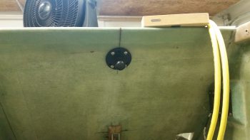
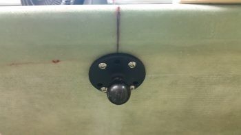
I then remounted the RAM mount to see how it fit and how it looks.  I’ll say that I’m very happy with this install.

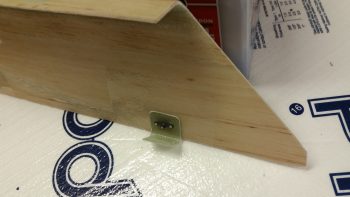
I also checked out my other hardpoint insert from last night.  This hardpoint is for the small wire bundle [meaning a bundle of small wires, not necessarily a small bundle . . . ] that will be routed just under the top edge of the kick plate that will run along the right side.  I was going to put an Adel clamp here, but with the slant of the top of the fuel line mount, it would just be too bulky.  So instead I mounted a metal tab that I’ll then be able to secure the wire bundle to.

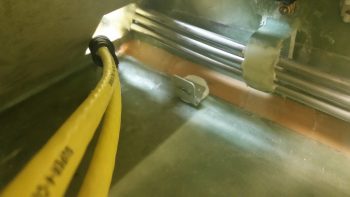
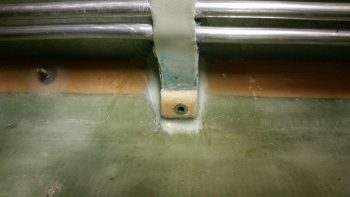
Here’s a shot a bit later after the 2 plies of BID that I laid up over the forward small wire bundle Clickbond cured.  I then set an Adel in place to check out the fit.  And yes, I realize that I still need to get in there and clean up the forward fuel line mount since it’s looking a bit messy.

Here’s another shot of the forward small wire bundle Adel clamp.  This too will be hidden from view when the kick plate is installed.

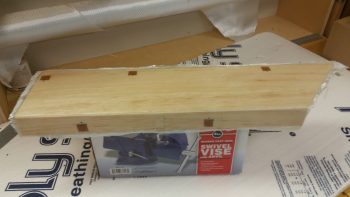
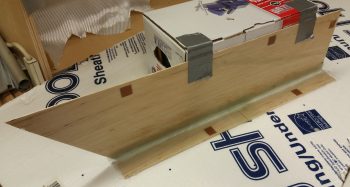
I then tweaked the scrap cardboard template I made up last night to determine the dimensions of the GIB right sidewall kick plate.  As you can see, it runs from the aft edge of the pilot’s seat to the front edge of the thigh support fuel sump front wall . . . specifically the right side bulkhead.

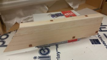
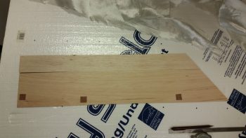
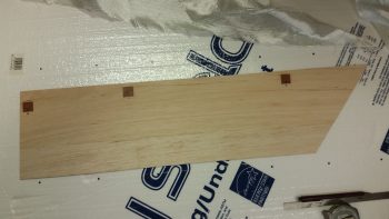
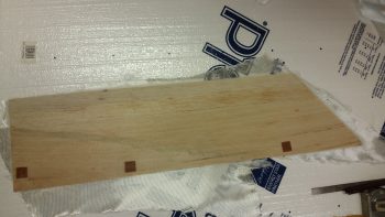
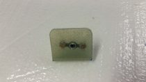
After I got the kick plate dimensions squared away, I then cut up a couple of pieces of 1/16″ thick Balsa wood that I had on hand just for this purpose.  I determined where my lower mounting hard points would be, then cut 0.7″ x 0.7″ phenolic pieces and inserted them into the Balsa kick plate to reinforce the areas on the kick plate that will get screwed in place to the sidewall.

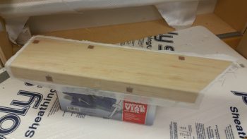
Here’s a shot of the other side, but with all the phenolic hard points and the two strips of Balsa wood micro’d in place.

I then laid up 1 ply of scrap UNI on the interior side of the kick plate.

I actually had a lot more planned to knock out today, but late in the afternoon my friends that are moving to North Carolina called and requested my assistance, so I was out most of the evening.  I did manage to trim up the layup on the interior kick plate when I returned many hours later.

I then cut more Balsa strips for the top, inserted 2 phenolic hard points and prepregged a couple of 1-ply BID layups.  I then laid up 1 ply of BID on each end, overlapping in the center.  This overlap helps reinforce the center a bit since I used 2 pieces of Balsa for the top, which precluded me from having to use an entire new strip of Balsa wood (remember: I’m cheap!).

I of course used a micro fillet and micro’d the phenolic hard points in place before glassing the interior of the top.

The top is 1.6″ wide, so I used 2.5″ for my width on the first ply of BID to glass both the internal top surface, but also overlap onto the kick plate side piece 0.9″.  In addition, I laid up an extra BID tape in the corner that was 1.5″ wide, so it overlapped about 3/4″ onto the top and side pieces of the kick plate.

In addition to my kick plate shenanigans, I also laid up a ply of BID over the Clickbond I floxed into place last night onto the heat exchanger’s upper duct, to be used for an Adel clamp to secure the heat restrictor valve cable in place.  I peel plied that layup, and below is a shot after it cured and I pulled the peel ply.

I then attached an Adel clamp to ensure the fit & finish was right… so far, so good!
Tomorrow is a planned day to help my friends moving to NC, so I don’t think I’ll get any building done at all.


Chapter 22 – Heat exchanger is one

Today I started off by Alodining the cooling/heating air valve plate.

And Alodining the heat restrictor valve (butterfly) plate.

I then installed the heat restrictor valve (butterfly) plate (note the 2 new standard screws used to install the plate).

I then mounted the upper/inlet duct to the heat exchanger body using RTV silicone.  I used RTV to make it easier to remove the upper/inlet duct if required in the future to tweak or repair the heat restrictor valve.

A few hours later I removed the clamps and cleaned up the excess RTV silicone from the upper duct attachment.  In addition, I floxed a Clickbond in place for the heat restrictor valve control cable Adel clamp.

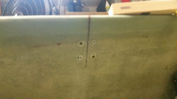
I also marked & drilled the last 2 holes for mounting the GIB RAM mount.

I then floxed the last 2 of 4 hard points for the final install of the GIB RAM mount.

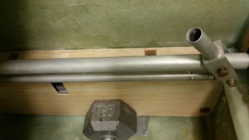
Finally, during my flox frenzy I floxed in a Clickbond (just above the forward fuel line mount) and a hard point (under the 10-pound dumbbell) for securing the small wire bundle that will traverse the fuselage from the front to the back of the fuselage.

Tomorrow I’ll continue working on the getting the GIB area components, including the oil heat & fresh air ducts, configured and installed.


Chapter 22 – Grommets & Gaskets

Today I started off by heading out to my local hardware store to buy another clevis pin to be converted into my heat restrictor butterfly rod (round 2!) and some other miscellaneous hardware.

Last night I already bought another 4-40 tap set to replace the one I broke.  I also looked for the same style clevis pin that I am converting for the butterfly valve rod, but none of them at Lowe’s or Home Depot, which were the only stores open, would work.

Upon returning home, I then floxed into place the rubber grommet that I configured to go in the hole between the main duct outlet into the heat exchanger’s upper duct (heating air inlet).

Here’s the backside of that same grommet.  This is the surface of the grommet that will actually interface with the gasket that I place around the matching hole in the heat exchanger’s upper/inlet duct (see below).

I had pondered a while last night and this morning on how to fill in the minor gaps between the heat exchanger duct entry & exit holes and the associated holes in the main duct.  I mounted the heat exchanger on its ductwork mounts and assessed the widths of grommets and/or gaskets (which I stumbled across during my pondering) that would be required.

I decided on using gaskets to mate up with the grommets I had just floxed into place. [Actually, I cut out this gasket below for the heat exchanger upper duct and floxed it in place at the same time as the grommet above.]

I also went ahead and floxed an AN960-416 1/4″ ID washer in place to use as a reinforcement sleeve for the heat restrictor butterfly valve.

A bit later I floxed on 1.5 gasket rings on the outlet hole on the heat exchanger’s lower duct.  I floxed in place one entire gasket ring first, then a half of one shaped basically in a backwards “C” in relation to the pic below.

When I floxed in the gaskets above, I also floxed in the 1/4″ washer on the other side of the heat exchanger’s upper/inlet duct.

The vast majority of the day was spent on constructing the heat exchanger’s upper duct heat restrictor butterfly valve.  After snapping my 4-40 tap off in modified clevis pin #1 (which was heat restrictor valve rod #2), I vowed to go super slow and clear the tap at every step this go-around.  Well, I got half way through the 2nd hole and wouldn’t you know it: my new 4-40 tap snapped in half!  Oh yeah, and this time I was fortunate enough to impale myself on the top of my thumb!  Ugh!
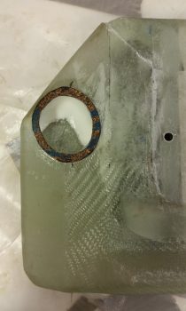
Well, after about 15 minutes I was finally able (and fortunate enough!) to remove the snapped off tap piece.  I then very carefully was able to use the two broken tap pieces to thread just enough of the remaining hole to mount a screw into it.

Later on, in the same hole –after using countersunk screws all day and well into the evening– as soon as I switched to my new standard stainless steel phillips head screws, the head snapped off immediately as I was just finalizing threading it into place.  Ugh!

After another 30-40 minutes of drilling out the snapped off screw, I was again thankful that the slightly undersized drill bit that I used didn’t wipe out my threads in that hole.  Going back to my CS screws seemed to do the trick and was definitely the safe option at this point.

Instead of taking a myriad of pics (which I failed to do anyway amidst all the mayhem!), I decided that I could better explain what I was doing with a video… so here you go:

I thought I would also knock out a quick side task and mount the GIB RAM air mount on the aft upper center of the pilot’s seat.  Now, I already have one that I mounted on the aft side of the pilot’s headrest, but I need to assess that one further since it may very will get moved or removed altogether depending on how well it plays with the canopy’s reinforcement crossbar.

Since I don’t have any extra of my preferred CG-style aluminum hard points, I simply used 2 RivNuts diagonally opposed in opposite “corners” and floxed them into the holes I made below (I’m using 4 screw hard points on this mount).  Later I’ll add the other 2 screw hard points.

Here’s a shot of the RAM air mount with the RivNut hard points mounted and floxed into place.  As you can see, I used my handy German clamp to keep the RAM air mount in place while the flox cures.

A couple hours later, after the flox had cured, I pulled off the clamp to reveal a nice “half-mounted” GIB RAM mount installed on the back of the pilot’s seat.

I then removed the ball mount and did a quick cleanup on the RivNut hard points.  Again, I’ll add 2 more hard points when I have them on hand.

Tomorrow will be a half build day since I’ll be helping my friends that are moving to NC.  But I do still intend to get a few things knocked out.