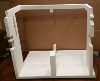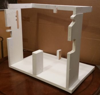
Chapter 21/24 – Finishing fuel valve base

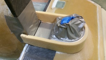
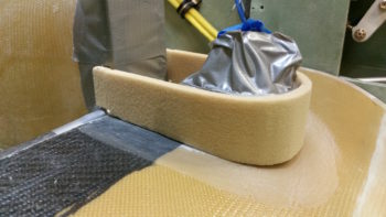
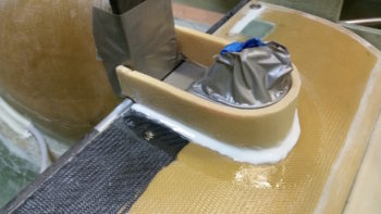
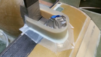
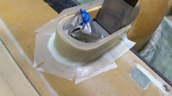
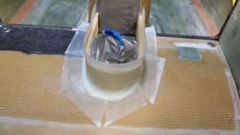
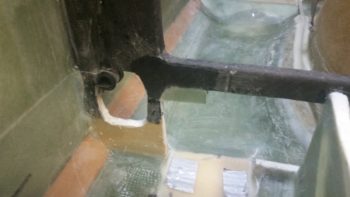
Today I started out by pulling the peel ply and cleaning up the side layups on the inside of the fuel valve pedestal base.  I was going to layup the entire rest of it, but then determined that since I had decided to use thin-walled 1/4″ aluminum tubing to make up the top rounded edge that I needed an inside wall to create the “U” shaped channel, or rounded groove, along the top edge of the pedestal base.

So I glassed the aft inside wall and just as I did with the side walls, dug the foam out of the edge of the thigh support plate below and filled with dry micro.  I then laid up 1 ply of BID overlapping slightly onto each of the previous interior sidewall layups.
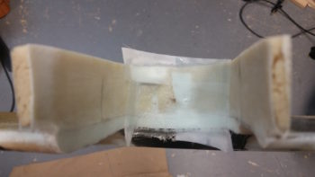
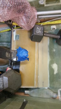
I then put the layup under a heat lamp so that it would cure even more quickly, which it did.  A little over an hour later I pulled the peel ply and cleaned up the layup.
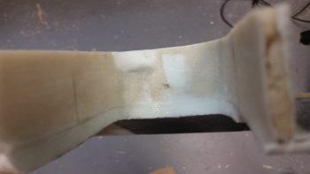
I then sanded the top of the pedestal base to ensure the top edge was even all the way around.  I then double checked the fit of the thigh support with its newly attached fuel valve pedestal in place around the fuel valve bracket.
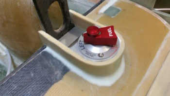
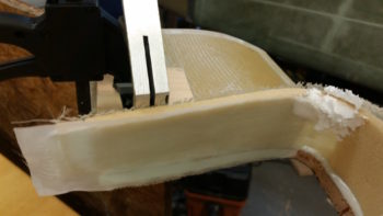
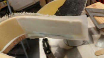
I then spent a good half hour bending and shaping a piece of 1/4″ 3003-0 Versatube to create the top edge of the fuel valve pedestal base.  I considered using Nylaflow, but it’s really hard to get it to straighten out.  I also considered just shaping the foam by hand, but I changed my mind in having a bit higher edge around the fuel valve bracket, so I figured the aluminum tubing was very light and would fit the requirement nicely.

I failed to get any pics of the my ensuing tasks, but after I ensured the fit of the 1/4″ tubing was correct I then set it in place and filled in the gaps with micro and then glassed over the entire pedestal base with 1 ply of BID.  I overlapped the BID ply onto the thigh support cover top about a half inch.  When the layup was done I then peel plied it.
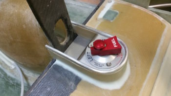
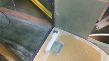
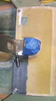
One question I had to answer was what to do on the front side of the fuel selector valve bracket, where its 6 attach screws reside.  Since this area will be the floor to my little impromptu bin –when required– I figured I would simply take some spare glass I had kept around for just such purposes, make a small insert plate, and then simply use a few dabs of RTV Silicon to keep it in place until such time as I may need to remove the fuel valve bracket.

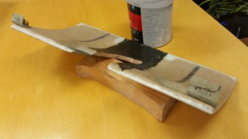
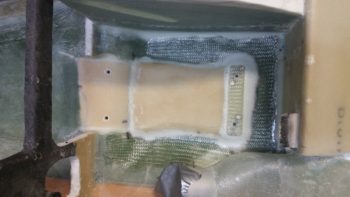
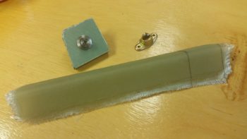
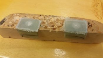
I found just such a piece of glass in my spare parts bin that looked to be about 3 plies thick.  I marked out (amazing how clear this stuff is btw!) the dimensions of the cover plate on the glass piece.
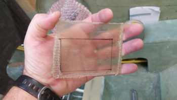
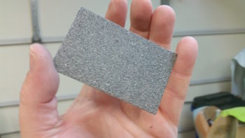
And then sanded it, painted it with 2 coats of darker granite paint, then hit it with a couple coats of clear (not all in one shot, I’m jumping ahead with the pic below).
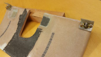
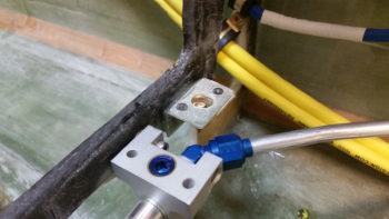
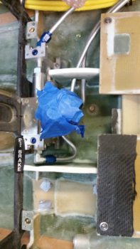
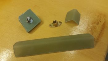
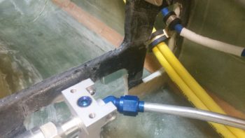
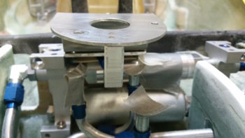
While the pedestal base layup was curing under the heat lamp, I then cut a piece of 1/16″ thick angled aluminum to create a support bracket tab that I’ll attach a nutplate to in order to allow me to secure the aft end of the cantilevered fuel valve bracket to the aft wall of the fuel valve pedestal base on the thigh support.
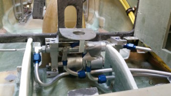
Here’s a closer up view of the fuel valve bracket screw support tab.
By this point the pedestal base layup was cured, so I pulled the peel ply and cleaned it up. I then spent a good half hour fitting the thigh support with its newly attached fuel valve pedestal in place around the fuel valve bracket.  With the extra ply or 2 of BID on the inside of the pedestal base wall, I had to do some aggressive sanding in spots and even resorted to filing a bit of the edges of the fuel valve bracket in some spots to get things to fit!  I underestimated how much clearance I would have so the fit was TIGHT!  But I eventually proved myself smarter than these inanimate objects and won! ha!
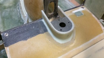
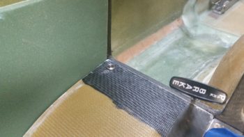
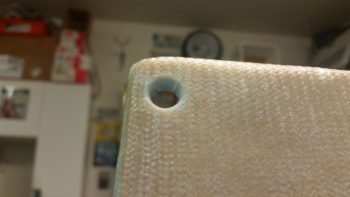
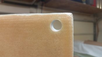
I then drilled a small pilot hole for the fuel valve bracket screw support tab.  I was off just a hair so I ended up making the hole bigger to use a #8 screw versus my originally planned #6 screw.  With my hole drilled, I then drilled and riveted the #8 nutplate into place on the front side of the fuel valve bracket screw support tab.
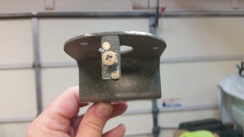
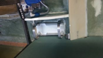
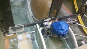
After beveling the hole with a countersink, I then tested out a screw to see how it fit.  I think this should do the trick nicely!  Also, while the pedestal base layup was curing I primed & painted the fuel valve bracket, as you can see in this pic.
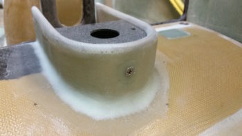
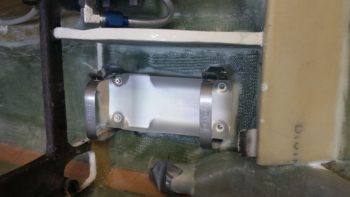
Here’s a shot of the painted fuel valve bracket in its thigh support pedestal.

I quickly mocked up the fuel valve top assemblies (no actual valve here) as well as the forward screw cover plate to see how it was all looking so far.  I’m liking it!
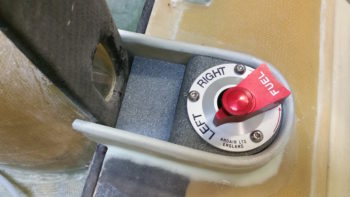
I then sanded down and prepped the thigh support cover for a couple of lighter coats of primer.  Here’s the results after the primer dried.
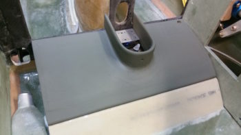
Then, for the grand finale of the evening, I hit the thigh support cover with a couple coats of the dark granite paint.  I have to say, I really like my interior paint scheme so far.
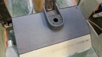
Tomorrow it’s supposed to rain, but if I can I’ll sneak in a few coats of clear on the thigh support cover.  I’ll finish getting the fuel selector valve and pedestal squared away, then move on to figuring out the left armrest console.  I will also try to sneak in finishing the wiring on the Dynon intercom on the instrument panel mockup.
 

Chapter 24 – Fuel Valve Pedestal

I started off today doing a fair amount of updates to my electrical connector pinout diagrams for a bunch of the work I did on the panel last night.

I then got down into the shop to figure out the fuel valve skirt, pedestal, base . . . whatever it is that you’d call one of things!  Since the fuel valve sits higher than the thigh support cover, then I clearly need something to keep things from falling down under the thigh support, but also I want it all to look finished as well.  Another important function of this piece is that it will keep the seat cushion in place and from sliding forward.

I started by assessing and brainstorming what I needed and what I wanted.  I had a general idea –obviously– but the particulars have been germinating in my mind since the day I decided to place the fuel selector valve in the location I did.  After taking some measurements and playing around with the top few ideas on my list, I decided to keep the top level all the way around, so it’s basically a giant “U”, just flipped forward away from you.

I measured the depth at the back at about 1.7″, although it ended up being a bit taller on the very back part. The front was about 1.3″ high.  The bottom line is that I knew that I could use some of my 2″ thick urethane foam for this task.  I then made a quick thin cardboard template to figure out the lengths and slope on the bottom of the pedestal.  I then used the actual thigh support cover turned upside down to get the interior shape and dimensions transferred to the foam.  I then measured 0.25″ from the inside edge to give my sides, with a bit thicker area on the aft end for room to shape it around the actual fuel valve.  I then used my jig saw and on VERY slow speed cut this out in a very cautious manner.

Once I got the pedestal rough top view cut out, I then marked the sides using my template.  I then cut the lines to give me a straight top and angled bottomed pedestal piece.

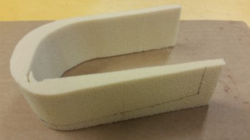
I then tried it out on the thigh support by wrapping it around the fuel selector valve.  Of course it took about 15 minutes of the trial and error fitting-sanding-fitting cycle to do this, but I fairly quickly dialed it in.  A bit ironically (or stupidly!) I had the sides reaching forward where I needed them on the rough cutout and then ended up lopping them off too short!  I then had to make a little extension piece for each side and use needles to keep them in place.

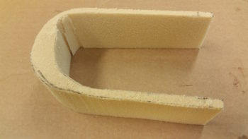
You may be wondering, looking at the pic below, why I’m extending the sides all the way forward . . . well, I want an area that is a little sort of a tray, or bin, if you will, to hold small bits either in flight or especially on the ground.

I then mixed up some epoxy with fast hardener and whipped up some micro.  When I set the fuel valve pedestal foam piece in place I did cheat a little and used a spot of 5 minute glue about mid-point on each side.  After about 5 minutes of ensuring it wasn’t moving anywhere then I finished adding the micro fillets all the way around as you see below.

I then laid up 1 ply of BID all the way up the pedestal walls overlapping down onto the seat thigh support about an inch.  After ensuring the layup was all good I peel plied it since I’m going to add another ply of BID over top of it tomorrow.

I then went for pizza & beer with a buddy of mine and we decided to go see a movie. After I returned I decided to glass the straight sections on the inside of the fuel selector pedestal so that I would have glass curing overnight.  Since I used urethane foam on this, the walls are a bit flimsy and I wanted to beefen them up a bit.  So I laid up 1 ply of BID on each inside straight wall of the fuel selector pedestal, peel plied them and called it a night.  For now I stayed clear of the aft curved wall.

As you can see I also added some micro on the inside aft curved foam edge… actually with a little bit of cheater alcohol in it to make it much easier to sand (I learned this trick from Randi of Cozy Girrrls fame).

Here’s a shot of the interior right side glassed with 1 ply of BID (and the alcohol micro).

And shot of the right side as well.

Tomorrow I plan on getting the fuel selector valve pedestal base completed and move on to figuring out and building the pilot left side arm support & console.  If I get a chance, because I didn’t today, I’ll try to work on wiring up the intercom on the instrument panel mockup as well.


Chapter 22/24 – Coming together…

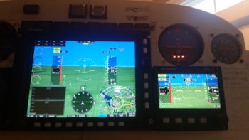
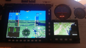
I started out today by doing a bit of electrical system administrivia until I could call GRT Avionics.  I then called them and left a voicemail detailing my tale of woe regarding the AHRS not talking to the HXr EFIS.  Within 15 minutes Mark from GRT called me back and within a minute I had the AHRS online.  It was simply a matter of setting the baud rate to 19200 (which I couldn’t find in the documentation) and it was off to the races from there.

While I had Mark on the phone we also worked through how to set & label some of the analog ports for my specific inputs such as the GIB thigh support fuel sump low fuel alarm. He had to do some digging around but he found the info that allowed me to set all my unique analog port inputs.

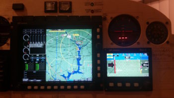
Here’s another shot with some slightly different screen views than above.

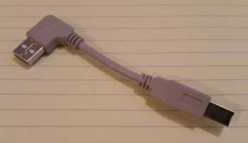
Upon checking my mail I found that I had received the 4″ USB dongle I ordered to connect the HXr EFIS display to the 4-port USB hub.  The USB hub connects items such as the Radenna SkyRadar ADS-B IN Receiver and by adding a little nub of a USB device also provides Bluetooth capability for the GRT EFIS system.  Specifically, with a small Android tablet the GIB will be able to see essentially the same info on the PFD as I do up front.

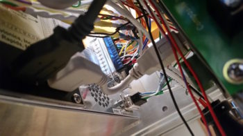
I then installed the USB dongle . . . this is the HXr EFIS side

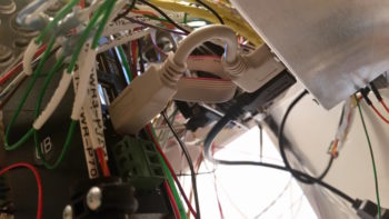
And here is the 4-port USB hub side.  You can see there is not a lot space behind (again, technically “in front of”) the EFIS display unit.

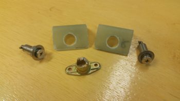
I also received the parts from ACS that I was remiss in ordering in a timely fashion.  With the #2 CAMLOC receptacle in hand I then pressed forward with the pilot thigh support cover CAMLOC locking tabs installation.  Two items worthy of note on these CAMLOC tabs is that, first, I realized I did not have countersunk rivets large enough to mount the CAMLOC receptacles to the tabs…. hmmm?  I quickly determined that a #6 countersunk screw would do the trick so I rounded up some of those (I only had the fancy SS hex drive #6 screws that would work) and some locknuts and got to work.

The second issue was that the left tab would not sit flush with the lower instrument panel cross piece and that it really required some force to get the thigh support cover to seat down in its proper position.  Of course I didn’t notice this until the receptacles were mounted in place and the CAMLOCs were installed tightly.  I fiddled around with it for a bit and realized it just wouldn’t work with the bracket at a 90° angle since it was obvious the angle must be more acute.  I don’t really like bending composite components with heat because things can go south quickly, but I bit the bullet and did just that.  I used a scrap piece of wood to mount the bracket to and then judiciously applied heat and was able to bend the bracket into a more acute angle and . . . Voila! . . . worked like a champ!

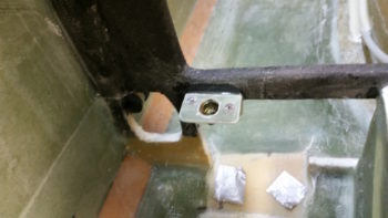
Here’s another shot with the thigh support CAMLOC brackets ready to be floxed into place into the fuselage at the base of the instrument panel bulkhead.

Ahhh, this familiar site!  What could it be??  Well, this time around of course it’s the thigh support CAMLOC brackets floxed into place and curing.

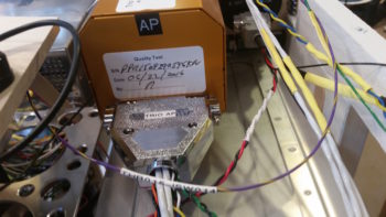
While the thigh support CAMLOC brackets cured, I prepped the Trio autopilot pitch servo for removal.  I needed to remove it for a twofold purpose: 1) I needed to repair 2 of its P3 connector pins that were NOT toning out, and 2) I needed to hook it up to the panel-mounted Trio autopilot control head for testing.

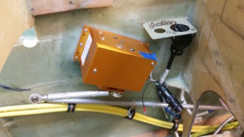
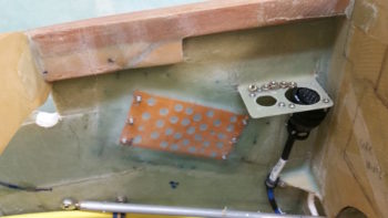
I forgot about the cool looking base floxed into place inside the right side of the nose, so I figured I would grab a currently rare shot of no pitch servo mounted on the side wall.

A bit later, after I confirmed the flox had cured, I pulled the weights off of the pilot thigh support cover and checked the fit of the now CAMLOC-secured cover.  Bottom line, as my buddy Dave B. from OZ would say, “It works a treat!”

Here are the left and right CAMLOC receptacle brackets now permanently floxed in place at the base of the instrument panel.

And here’s a shot of both thigh support CAMLOC receptacle brackets.

As I finished wiring up the Trio Pro Pilot autopilot into the instrument panel mockup, I first repaired the 2 errant connector pins on the pitch servo and then connected both servos to the Trio autopilot control head.

I also ginned up a quick little mount for a temporary autopilot disconnect switch just in front of the intercom.  I picked this spot since my actual autopilot disconnect switch is on the control stick.

BTW, the connector you see in the Adel clamp attached to the outside upright of the instrument panel mockup base is the P5 connector, which attaches to the control stick cable connector.

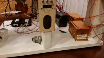
Although I temp-mounted the GNS480 GPS antenna puck last night, I thought I’d get a shot of that and the newly connected Radenna SkyRadar-DX ADS-B IN receiver sitting down low in front of the instrument panel mockup base.  You can see that I zip-tied its own GPS antenna puck to the top of it, this making GPS antenna puck number 5 that is currently connected to this panel mockup!  If you’re curios, here’s the list:

      1—GNS480 GPS Receiver
      2—HXr AHRS
      3—Mini-X EFIS
      4—TruTrak ADI
      5—Radenna SkyRadar-DX ADS-B Receiver

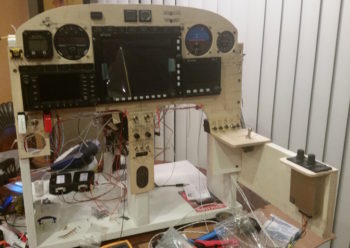
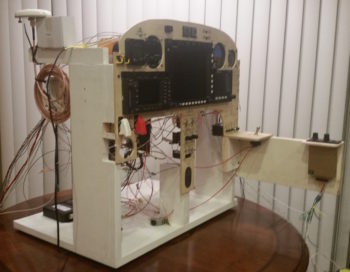
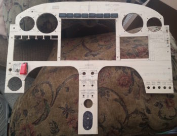
Ok, so here’s the latest shot of the mocked up instrument panel, ready for official power-on test #2 . . . which means that I am really just checking out my Trio autopilot wiring installation.

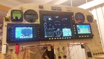
And here’s the panel with power fired up again.  A quick note that not only did I resolve my AHRS connection issue, but I was able to tweak my GNS480 external annunciator lights and rewire the OAT probe on the MGL clock, so all of my 3 issues from yesterday are resolved.

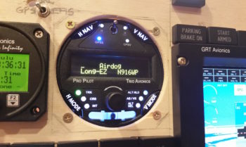
My last act of the evening, as I was doing some minor configuration inputs on the Trio autopilot, was to personalize that sucker to make it MINE!  [Note the blue GPSS LED light lit up as the Trio AP is talking to the GNS480 GPS receiver…]

Alrighty then my friends, tomorrow I plan to work on both the thigh support cover piece that will wrap around the fuel selector valve to finish off the thigh support install, and also work on finalizing the Dynon intercom wiring connections as much as possible.


Chapter 22 – Light it up!

I started off today by cutting 2 small pieces of wood and attaching them to the existing panel mockup base with wood screws.  The lower 3/4″ plywood plate, mounted vertically just below the left-side row of circuit breakers, does double duty in holding up the second horizontal plate, and at 4.5″ in depth mimics the top of the lower LHS side hole in the instrument panel bulkhead, the highest point for running wires from under the left armrest to behind the panel.  In other words, all the wires going to/from the intercom to behind the panel must be run below this plate.

I mounted the second, thinner plate on top of the arm intercom-positioning jut-out at the base of the panel just forward of the row of circuit breakers.  This plate mimics the left armrest console aft of the panel and forward of the control stick. Since I plan on mounting my master switch and both “mag” switches here, I went ahead and mounted my master switch in its approximate position.  In this setup I’m bastardizing the master switch to serve as a power ON/OFF between battery power and main buss feed.

Over 12 hours later here is the panel –with about as many of the wiring cross connections completed as possible– ready to be fired up for the first time.

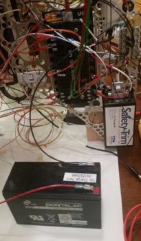
After I double checked all the connections, I set the battery in place and attached the leads.  My battery was at 13.8 volts, which gave me a good bit of time to test out the panel.

I took this shot a fair while later after I applied power to the panel.  I had left the GNS480 off for quite a while since it’s a bit of a power hog as I initially worked on configuring the GRT boxes.

Currently, I have 3 main issues I need to address, one major, 2 minor:

  1. My HXr won’t recognize the AHRS unit.  I’ve double checked all the connections, power, RS232 etc.  I’m stumped so tomorrow I’ll contact GRT.
  2. Three of my powered GNS480 external annunciator lights (Korry) lit up even before the unit was powered on.  Clearly I’ll need to figure this out.
  3. The OAT probe is inop on my nifty little MGL clock…. and has never worked.  I’ll contact MGL tomorrow as well.

Barring the usual snags, I’m super happy with the panel.  Tomorrow I’ll probably get back into the shop for at least a bit, but I do want to get the AHRS issue resolved.


Chapter 22 – Official Rabbit Hole!

Yes, panel build: Day 2.

Today I started off by updating my connector pinout diagrams, reviewing the upcoming connector pinouts and then printing up 2 batches of wiring labels.  I had to improvise with some larger yellow wires labels since —surprisingly— I’m out of wire label cartridges.

My goal today was to start on the J4A (front side) PQD (Panel Quick Disconnect) connector, but that quickly devolved into working on the prerequisite connector pinout on the Adaptive AHRS for the HXr EFIS.  The AHRS is the recipient of a number of wires from the J4A connector, so it was natural to finish this task at this point.

I swapped out a number of wires on the AHRS wiring connector for different colors since some of GRT’s pre-installed wires didn’t match my color coding.  I thought about leaving them as is, but it’s a fairly easy task to swap them and will make any future wire-hunting/tracing tasks go much easier if the wires keep the same color on each side of the connectors.  I also pulled a few pre-installed wires that I didn’t need.  Thus, with the AHRS wiring connector squared away, I installed it and then worked on hooking up the wires coming out of it to points yonder on the panel.

At the aft right corner of the Triparagon… a shot of the PQD connector trio: P6 (currently unpopulated), J3 Mini-X connector (on side, vertical) and J4 HXr (top, horizontal).  The relay in the foreground is Relay 9, which handles the COM1 ↔ COM2 swap.  I apparently ran out of wire labels after I constructed it, so it took me a good half hour to tone it out and deconstruct what in tarnation I was up to when I made it!  And with a 3PDT relay, it took a bit of head scratching.  After I got it all figured out and did some quick masking tape labeling, I sent the wires off in their required directions.

[NOTE: This exercise in near-“futility” definitely reinforced to me the importance of wire labels.  No matter how in-depth we get into a certain subtask, 6 months down the road all those details are lost –at least to me– and I need to “relearn” what I did!  Diagrams and wire labels are the only way for me to pick up where I left off months or years later on these countless wiring components and press forward quickly].

Here’s a closer shot of the PQD bracket and connectors.  The front (Triparagon) sides of the J3 (Mini-X) and J4 (HXr) connectors are for the most part complete.  There’s another 8-10 wire connections that will need to be added once it’s all actually installed into the aircraft.

I spent a few hours constructing the 3 x ARINC 429 and 1 x RS232 shielded wire cables that all route through a centralized grommet in the Triparagon from the J4 connector to the GNS480.  The pic below shows these cables from the right side of the Triparagon.

And here are the 4 ARINC 429/RS232 cables on the left side of the Triparagon, ready to be terminated into the GNS480 back plate D-Sub connectors (by the way… I installed the D-Sub connectors on the GNS480 back plate).  I only terminated the RS232 cable at this point since it had standard sockets, whereas the other ARINC 429 cables require High Density pins since they get terminated into connector P5 (high density).  I’m waiting until I get all the standard D-Sub pins & sockets crimped before I reset my D-Sub crimper for high density crimping.

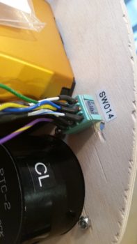
Two of the ARINC 429 and one side of the RS232 connections I highlighted above also feed the Trio Autopilot EFIS/GPS source select switch, the rather diminutive Switch #14. On the right side of the pics above & below, you can see the cross connect cables that are tied into the GNS480’s ARINC 429/RS232 cables (spliced in just before the wires enter the GNS480’s connectors) as they run up over the GNS480 to tie into Switch 14 on the panel.

Here’s a shot of Switch 14, the Trio Autopilot EFIS/GPS source select switch, after I terminated the connections by soldering 9 wires to it: 5 connections come from the ARINC 429/RS232 cable group, 3 from the Trio AP control head, and 1 connection from the GRT HXr AHRS GPS signal.

A closeup of the 9 wires connected to the Trio Autopilot EFIS/GPS source select switch (Switch 14).

To get the wire connection lengths dialed in from the Trio autopilot to Switch 14, I had to install the massive D-Sub wiring harness on the back of the Trio autopilot.

Here’s a closer shot of the installed D-Sub connectors on the GNS480 back plate.

In addition, I also mounted the air deflector on the GNS480 back plate.

Lastly, I used some of the extra terminated wires that I pulled off the GRT wiring harnesses to make up much shorter harnesses for both the HXr and Mini-X magnetometer connectors.

I suspect that my Aircraft Spruce order should be in the day after tomorrow, so that gives me one more full day to knock out as much as I can on the panel before getting back into the shop.  I think I should be close to having the panel pretty much wired after another full day of working on it.


Chapter 22 – Initial panel wiring

I started off today making a quick plan for wiring up the instrument panel.  To be clear, the instrument panel is mocked up, but the wiring I’m doing now is the real deal… always subject to some upgrades (read: changes!).

The plan was to get the TruTrak ADI and MGL clock rewired since I pulled them off the P6 PQD connector and am now running all the wires from point A to point B, as I noted in yesterday’s blog.  I did get them rewired, but not without the requisite issues along the way.  Nonetheless, in the end they are wired & labeled correctly.  So, check one!

My next task was to get the wiring harness for the HXr EFIS built, which is made up of wiring leads of the 3 HXr connectors: A, B & C being consolidated into one 37-pin D-Sub connector which makes up side B of the J4 connector.  Again, as I noted yesterday, since I’m a hair short on connector positions, I pressed a 4-pin AMP CPC connector into service to handle the HXr’s primary, secondary and tertiary power wires along with the single ground wire.

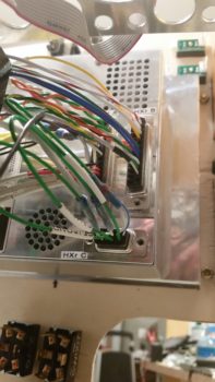
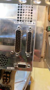
In the pic below, J4B is at the top left.  Then clockwise are HXr B, HXr A, P7B and HXr C connectors.  HXr A and HXr B have a smattering of different types of connections, while P7 –again- is only for power and HXr C is all ARINC 429.  In addition, as you can see I didn’t just get the wires cross-connected, but all labeled as well.  Finally, any wire loops you may see are the loopback grounds for the shielded wiring.

The 3 HXr EFIS connectors, in their final, populated state (l to r) HXr C, HXr A, HXr B.

I then did a test fit of the HXr wiring harness.  Below is a top-down shot.  Yes, it is REALLY tight, but it all seems to fit so far.

And a shot of the 3 HXr connectors . . . installed.

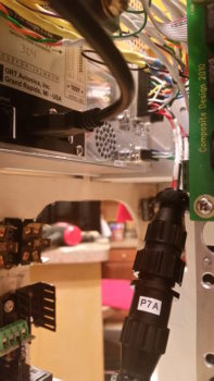
And a shot of P7 connected as well.

Tomorrow I’ll continue to work on the panel with the goal to get the front (Triparagon) sides of the J4 (HXr) & J3 (Mini-X) connectors wired up, as well as the last big bubba left: the GNS480 GPS unit [the Trio autopilot will be a big task as well, but it came with a populated D-Sub wiring harness, so labeling the wires and terminating them with connectors will be the time-consuming part on the autopilot].


Chapter 22 – Yep, the boring stuff

Over the past couple of days I’ve had a heavy social calendar with old friends wanting to get together, which is always great.  On Friday and Saturday I squeezed in maybe 45 minutes each day to work on updating my electrical system diagrams, starting with my connector pinout sheets.

Today (Sunday) I started off making a bit of noise by cutting a 19.5″ long x 6″ high arm to mount to the right side of the instrument panel mockup base to allow me to mount the intercom very close relationally to where it resides in the actual aircraft.  Although this intercom is small in size, the whole aft end is nothing but a D-Sub connector and there are a lot of cross connections required from the panel components.

With my requisite construction task out of the way, I then started in on what I’ve been trying to get to for the past couple of days: my electrical system diagrams.  One way I keep track of all my connectors is that AMP CPC connector ID codes start with “P” (“plug”) while D-Sub and mini-Molex connectors start with “J” (“jack’).  This scheme also gives me more numbers on hand for each series, since there are a fair number of distinct connectors in this airplane.

Well, besides the myriad of other updates I needed to do, including finalizing the switch out of circuits coming off the big 24-pin P6 PQD connector, I also created a new 4-pin AMP CPC plug (P7) for the GRT HXr power wires.  Concurrently, I reclaimed its previous J10 tagline for the 25-pin Audio Mixer D-Sub connector.

Finally, if a connector is merely planned and has not been fully pressed into use, I may switch them around in an effort to keep the numbering scheme so that the low numbers start at the nose and get bigger as they move towards the back of the plane (i.e. J1 towards nose, J12 in hell hole, for example).  Well, I stole the P7 moniker from the Trio roll servo that resides in the engine compartment and its new label is now P8.  This of course required physically removing labels and adding new ones.  A bit of a mundane task in doing all this, but in the end I feel wholly worth it in having a well organized, more easily maintainable, electrical system.

With the reallocation shell game complete, I then went to work updating my connector pinout diagram sheets.  After those were complete, I then did a 100% review and update of all my electrical system diagrams.  I added the 6 new GNS480 external annunciators to the panel diagram (#1) and tweaked all the other diagrams as well.

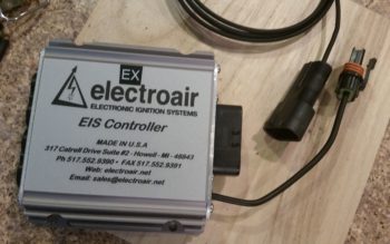
One major difference in my updates this time around, on a number of occasions I noted exactly how long a certain wire was that was included by the manufacturer on their wiring harness, and then approximated how much more I needed to add to complete the physical wire run.  For example, on ElectroAir’s EIS Controller, that will sit in the GIB headrest, the main 20 AWG yellow wire that runs forward to the EI (“mag”) switch on the console is 6 feet long coming off the EIS Controller’s wiring harness.  Not long enough to reach the front, so I annotated that on the wiring diagram.  Now I know to have or reserve some 20 AWG yellow wire to extend the EIS Controller switch wire.

Beyond that, a lot of my diagrams were simply the old versions with my chicken scratch notes annotated on them, while the electronic versions were up to date.  I took the time to verify the info was correct, updated other info as need be, and printed off a fresh copy of every electrical diagram.  I’m sure I’ll need to do this a another few times before the plane is finished, but as of now I have a really good baseline for my entire electrical system being up to date.

As for the actual build, I’m waiting for the CAMLOC receptacle that I ordered from ACS to arrive before I press forward with the pilot seat thigh support installation, and then the subsequent tasks that follow.  I also made some other minor orders for some now known USB cable lengths and avionics panel mounting hardware.  Thus, in the next few days, until the CAMLOC receptacle arrives, I will take the opportunity to focus on getting the panel wired up.


Chapter 22 – More panel stuff

Today was still all about the panel mockup.  With a number of changes I’ve made to the wiring on the back side of the panel, I needed to check those changes to ensure they would fit my design requirements.  Once I determined that I was heading in the right direction, I made the changes which required a fair amount of pulling wires out primarily out of the PQD P6 connector and then re-adding them to other connectors and/or splicing them directly into the Triparagon side wiring.
The main reason behind all this is I had a major rethink on the process of removing the panel.  I had giant brain blank earlier when I didn’t take into account that my removable panel component wiring wouldn’t be routed through one giant opening in the panel, since the current composite “shadow” panel will in most respects mirror the outer 0.063″ 2024 aluminum panel overlay.  This means as wires from each instrument traverses their respective holes to a common connector point, then if I tried to remove the panel after disconnecting that one connector (eg PQD P6), all the wires would get hung up at the connector as the panel was being removed.

Hard to follow?  Think of an octopus on the back side of the panel reaching each of his 8 tentacles through a different hole on the panel. Then think of him grabbing ahold of 8 rods larger than each hole.  You can’t pull the octopus away from the aft panel unless he releases all the rods, and you can’t pull the rods away from the front of the panel without squishing poor Mr. octopus against the back of the panel.  In this scenario though, all the rods (instruments) are attached to the front panel overlay and Mr. octopus represents the panel quick disconnect (PQD) connector, while his tentacles represent the respective wiring to each instrument… hope this analogy makes sense.

Ok, so I removed the PQD P6 connector out of the equation for my MGL Clock, TruTrak ADI, and a few other panel mounted components.  Thus, instead of A→B, B→C, I now simply have A→C with B (P6) cut out of the pic. Of course this change entailed lopping off wiring terminating pins & sockets and then re-terminating the wires by splicing them together.  It also required a fair amount of wire relabeling as well.

My new method of panel removal for these smaller components will be to simply remove the connector at the back of each component.  In the end, it should only add a few minutes to panel removal, and will also allow me a cleaner wiring harness overall since I won’t have as many convoluted wiring runs.

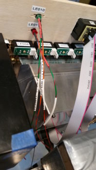
In line with all I stated above, I finished the wiring for the red & green Gear/Canopy warning system wires that I initiated yesterday.  I soldered spliced the wires together for a straight shot from LED light to warning module on one side, and LED light to E-Bus power on the other.  I of course labeled all the wires as well.

If you recall, I have 3 connectors that make up the Panel Quick Disconnect (PQD) connectors: 24-pin AMP CPC, 37-pin D-Sub, and 15-pin D-Sub.  On the PQD scheme, I switched things up a while back by claiming the 15-pin D-Sub to handle the GRT Mini-X wiring only, while the 37-pin D-Sub handles the GRT HXr wiring only.  However, since I didn’t have enough pins in the 37-pin D-Sub for all the HXr connections, I decided to separate out the 4 power/ground wires and connect them through a mini-Molex connector.

Thus, since the 24-pin PQD P6 connector is an AMP CPC connector, when I pulled the main, secondary, tertiary and ground wires from the P6 connector, I would need to cut off these connectors to re-terminate the wires for the new 4-pin mini-Molex connector. I then remembered that I possibly had a spare 4-pin AMP CPC connector, and after some searching around –Voila!– I did.  I weighed the AMP CPC vs the mini-Molex and the difference was the AMP CPC being 0.08 oz heavier.  With a much better & more robust connection, plus not wasting a couple of dollars in lopped off connectors (which I’ve already had a fair amount of!) I pressed forward with simply removing these wires out of the P6 connector and popping them into my new P7 connector.  So HXr power wires on the Triparagon side are complete.

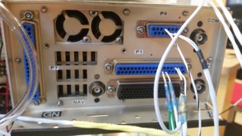
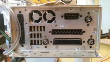
I guess my old military side came out because I then went through and labeled all the D-Sub and antenna connectors on the back panel of the GNS480 GPS unit.

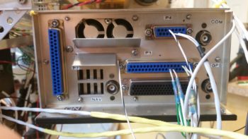
And the back panel of the GRT HXr EFIS.

The moving of wires off of one connector onto another connector, or connecting straight to a wire lead all required a ton of annotations on my connector pinout diagrams.  I have company coming in tomorrow, and a heavy social calendar this weekend, but I will try to get all these changes on my electrical system updated ASAP.  After I get the required adminstrivia updated, then I can get back to actual shop work.

Chapter 22 – Fun’s over…back to work!

I started out today by re-drilling the holes in the pilot seat thigh support CAMLOC receptacle mounting tabs where I had added 2 plies of BID (no pic).  I was ready to install the mounting tabs with CAMLOCs in place, but realized it wasn’t the best idea with only one CAMLOC receptacle on hand.  Obviously I need to order one, so I added it to the small ACS order that I’m compiling.

I then started reviewing what I had left to finish my panel mockup.  With the 2 AG6 warning annunciators, I’ve ridded my panel of all extraneous warning lights save 2 (one red, one green) that specifically are allowed on my panel for the JBWilco Gear & Canopy warning system.  Interestingly, out of all the LED panel assemblies I have in stock, I did not have a green light.  I had the nice Cadillac of LED panel lights that my friend Eric at Perihelion Designs peddles, of which I have a Red & Amber version of, but I don’t have a green.  I went to Eric’s site, but alas I didn’t see them on there (I’m sure even if I missed it he would sell me one).  Interestingly I found Eric’s nice LED assembly on Stein’s site… ok, I had an identified source of supply for my green light!  Check.
So I marked up the panel using the sexy red LED panel light assembly I had on hand … Uh, Houston we have a problem, and it’s space…. not outer space, but space for the fancy robust flange included with Eric’s LED light assemblies.  They could easily fit, but at almost 0.45″ in diameter, they do take up some real estate!

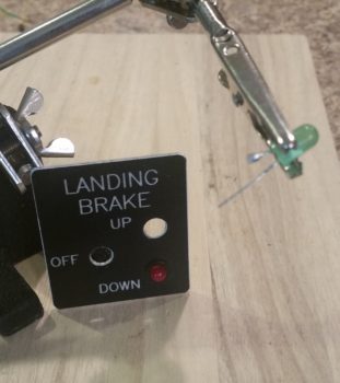
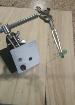
In my quest for a green LED, I did run across Jack Wilhelmson’s Landing Brake switch plate that included a red and green LED… bingo!  Of course I had to rid the LEDs of their soldered component webbed matrix bondage stuff, but after I whittled them all down I ended up with a green and red LED light, albeit with short, solder-encrusted stubby leads. Knowing how these lights look in a panel, plus the diminutive plastic “grommets” used to hold them in the panel, I decided to go with these.  Plus, I really like repurposing stuff that might otherwise just end up in an old parts bin!

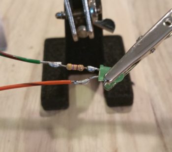
I checked Jack’s included landing brake wiring schematic (I’m too lazy to attempt deciphering the resistor color band codes) to determine that he did in fact use a 470 ohm resistor . . . perfect!  Thus, I reused that as well in my evil plan here.  I soldered Jack’s repurposed resistor to Jack’s repurposed green LED.  I then added the appropriate color-coded 22 AWG wire leads by soldering those into place as well.

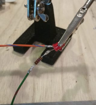
I then soldered one of my benchstock 470 ohm resistors to the red LED, and also soldered on the appropriate color 22 AWG leads.

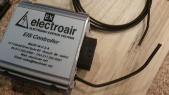
While I had the soldering iron fired up & soldering kit ready to go, I knocked out a quick soldering task that I had open on the books: I ridded myself of a big, bulky, heavy and unnecessary deutsch connector that resided on the ground wire to my ElectroAir EIS Controller.   To be clear, in my latest phone call with the ElectroAir bubbas, I specifically asked if this would present any issue: obviously they stated no, the connector was simply in place for ease of installation.  In my case, it would not make installation easier . . .

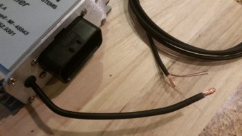
So, I unceremoniously lopped off each side of the deutsch connector.

I stripped the wires and prepped them for splicing (notice the longer 3-strand “tail” on the top wire).

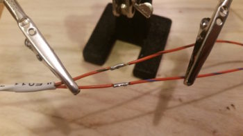
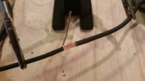
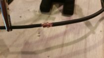
I then joined the wire together, wrapped the lead (“tail”) around the joined wire bundles to secure the wires together tightly, and then soldered the whole affair.

I then added a piece of heat shrink to finish out my ElectroAir EIS Controller ground wire streamlining . . . Voila!  Aaah, much better.

Unlike my cleaned up ground wire above, my next task was to add complexity to the instrument panel mockup base by creating a mounting frame for the Triparagon, since it’s such an integral part (read: epicenter) to the electrical and avionics systems.

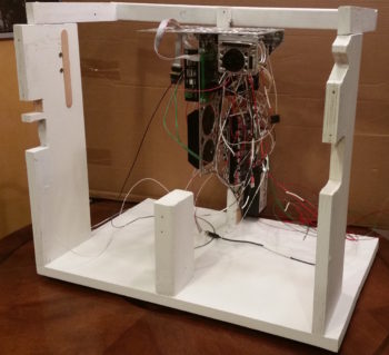
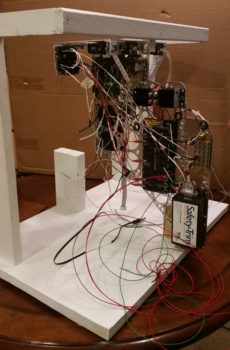
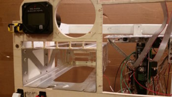
I added a top frame assembly that mimics the F28 bulkhead, including a mounting tab for the Triparagon.  On the forward bottom side I simply screwed a small block of wood in place.  I then slathered on a couple quick coats of white primer to make it all match and let it cure while I was drilling and cutting out mounting holes in the panel mockup.
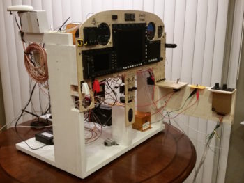
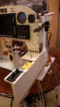
Quite a few hours later, I brought the dry instrument panel mockup base upstairs, since it was ready to be pressed into service.

I then mounted the Triparagon in place.

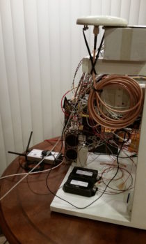
Here’s an aft/side shot of the Triparagon.

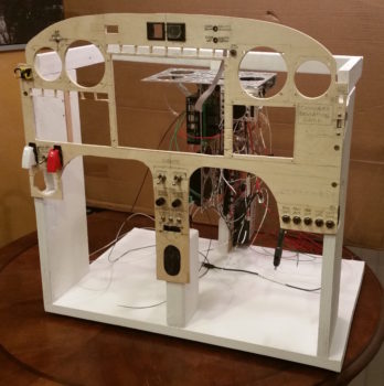
I then mounted the ELT control head (bottom component on center strut), switches and circuit breakers into the panel mockup.  Right as I was getting ready to mount the panel into the base, I realized I had left out the diminutive Push-to-Test button for the top row Korry lights [I haven’t even address the actual wiring for the GNS480 external Korry light annunciators yet].  So after figuring out it’s exact location, I hauled the panel down to the shop and quickly drilled the mounting hole (with some requisite panel-thinning immediately behind it so it would fit depth-wise).  I then mounted the panel onto the base front uprights.
I then mounted the compass card, GRT Mini-X EFIS, TruTrak ADI, and MGL clock.

I didn’t realize it until much later, but for some reason I inexplicably mounted the MGL clock on the front (outside) of panel vs from the back.  After looking at it for a bit, I realized that I really like it this way.  I will try mounting in the traditional manner and assess, but I am really liking how it looks mounted on the front side of the panel.

I then went offline for a bit panel-wise and had to dig into the Garmin GNS480 unit manual for the details on installing the backplate onto the mounting tube (bracket).  My GNS480 came with the tube and an entire new mounting kit replete with a myriad of tiny screws, washers, etc. to assemble the backplate, D-Sub connectors and antenna connectors.

Once I got the backplate installed onto the mounting tube, I then mounted the tube into the panel mockup.
I then spent the next 2+ hours installing the remaining panel components: GNS480, GRT HXr EFIS, and Korry indicator lights.

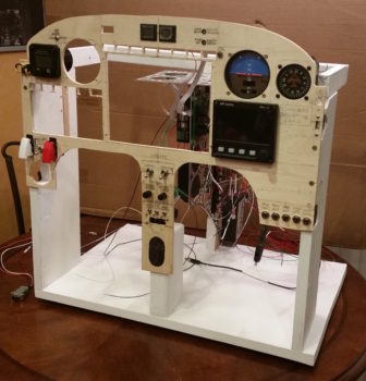
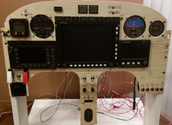
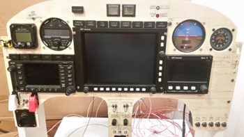
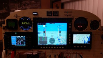
I also mounted the 2 LED warning lights that I soldered up previously.  Here’s a shot of just the instrument panel . . . closer to what you would actually see in the plane.

And an even closer shot of the panel components.

Over the next few weeks/months I’ll do all the wiring and cross connects for the panel & Triparagon.  I would like to get it wired to the point that in the next 7-10 days I can fire it up and check out the HXr to ensure all is good with it.  As for now, I’m done with my major digression and will get back to working on the pilot seat area & left pilot armrest console in my continuing quest to finish off the lion’s share of interior cockpit component installs and configuration.  This will of course facilitate closing up the top of the nose and getting the canopy installed.


Chapter 22/24 – ELT bracket installed

I started out today pulling the peel ply from the ELT mounting bracket base layup.  I then cleaned up the layup and drilled access holes for my 4 embedded K1000-6 nutplate assemblies.  Finally, I pulled the plastic wrap out of the mounting holes to reveal nice, ready to go screw mount holes.
I then did a test install of the ELT mounting bracket.  All was good except at the front, where the existing floor of the fuselage slanting forward up to, and including, the bottom panel bulkhead lip (the stuff that I cut out to make the ELT sit flat) was physically too close to the mounting bracket and was keeping the mounting clip from getting inserted onto the latch hook.

It took me 3 rounds of cutting, grinding and sanding to finally get it dialed in just enough where I could get the upper latch ring down over the lower latch hook.  With that action, my ELT mounting base is officially installed!

I took a quick shot showing the clearance to the left of the ELT mounting base with the left armrest console sidewall.

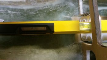
I then grabbed my digital level and tested the angle of the ELT mounting base: only 2.9° nose high… I’ll take it!

With ELT mounting bracket “sideline project” out of the way, I started on the final task #3 of my 1-2-3 task list that I ginned up early last week for getting the pilot seat thigh support finished.  In my mind this 3 item list was going to take 2 days . . . and here we are almost a week later!

Anyway, task item #3 is getting a CAMLOC installed in each forward corner of the thigh support top/cover plate (or “floor” as it’s called in the plans).  I rounded up a 3/8″ thick piece of foam that was glassed both sides to mimic my thigh support cover.  I also rounded up the 7-ply glass bracket stock I had made up this past weekend.

I marked the bracket stock to cut out a bracket for the CAMLOC receptacle, which I only have one for testing purposes at this point [NOTE: All my other “CAMLOC” receptacles for the engine cowlings are the SkyBolt variable adjustable type].

I then trimmed the bracket stock and lopped me off a nice bracket from it.

A bit later, here’s my 2 CAMLOC brackets for the pilot seat thigh support, with holes drilled for the receptacles.  As you can see I also grabbed another stud and grommet, which I’m also testing to determine my preference.

I then drilled the stud/grommet thru-holes both left & right in the forward corners of the thigh support cover plate.

Here’s a shot with both stud/grommets in place on the thigh support cover.

I then did some multi-faceted layups.  I started by slathering flocro in the thigh support corner stud/grommet thru-holes (after I prepped the holes by digging out the foam around each hole).  I worked the flocro in nice and good so that it was set inside & past the edges of each hole.

A few hours later I redrilled the thigh support corner stud/grommet thru-holes for nice strong holes with very clean edges.

I needed some more surface area for my thigh support CAMLOC receptacle brackets to mount to, so as part of my multi-faceted layups I used some flocro to mount a couple ~5/16″ thick foam pieces (that I previously shaped) into the upper outboard corners of each of the panel bulkhead’s “map pockets”.  I then glassed patches of BID –2 plies front, 1 ply aft– over these newly inserted corner pieces.

I then peel plied the layups and left them to cure.

A number of hours later I pulled the peel ply and razor trimmed the freshly glassed CAMLOC receptacle brackets’ backplate mounting extensions.

The last bit of glassing I did on the days’ big layup-palooza was to added 2 plies of BID to the top of each thigh support CAMLOC receptacle bracket.  I noted when the CAMLOCs where in the closed/fastened/locked position, that the stud was just slightly proud of the grommet.  I figured 2 plies would get me acceptably closer to a flush stud inside the grommet.  Plus I’ll have paint on the thigh support cover, so I should be able to dial in the depth of the stud to match the grommet on each side.

With my shop work complete for this evening, I then spent over 2 hours working on my mockup/test instrument panel.  I drilled out & jig sawed the 8 holes above the HXr EFIS (PFD) for the Korry status lights, and then another 6 holes above the GNS480 GPS unit for the external GPS annunciator lights (also Korry).

I then spent a good amount of time figuring out where the remaining panel components, mainly switches, will go.

Tomorrow I hope to finish up the pilot seat thigh support CAMLOC install and the instrument panel mockup configuration.  For the panel I’ll probably construct a behind-the-panel cross bracket to mimic the F28 bulkhead so that I can install the Triparagon on the panel mounting base.