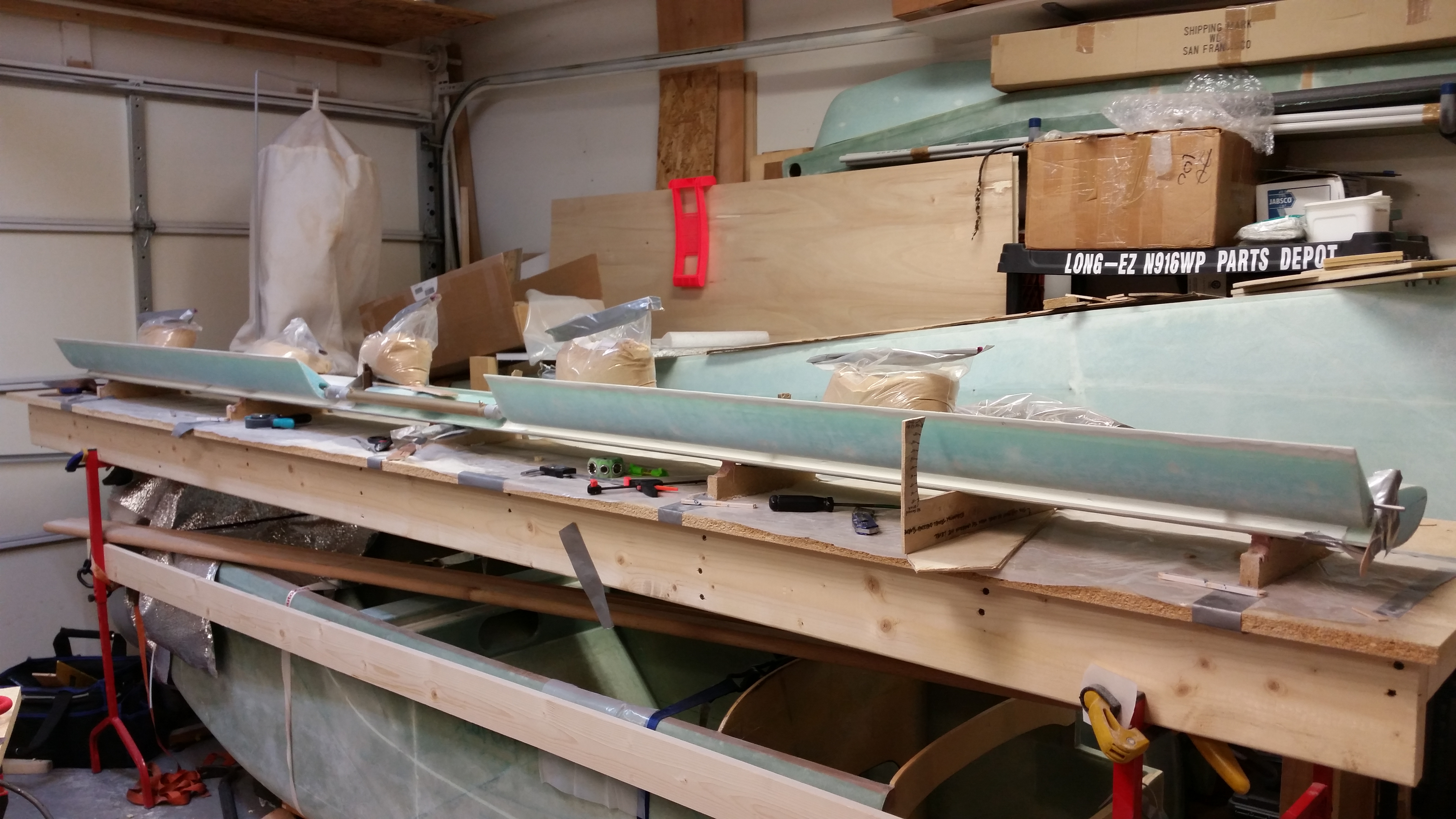
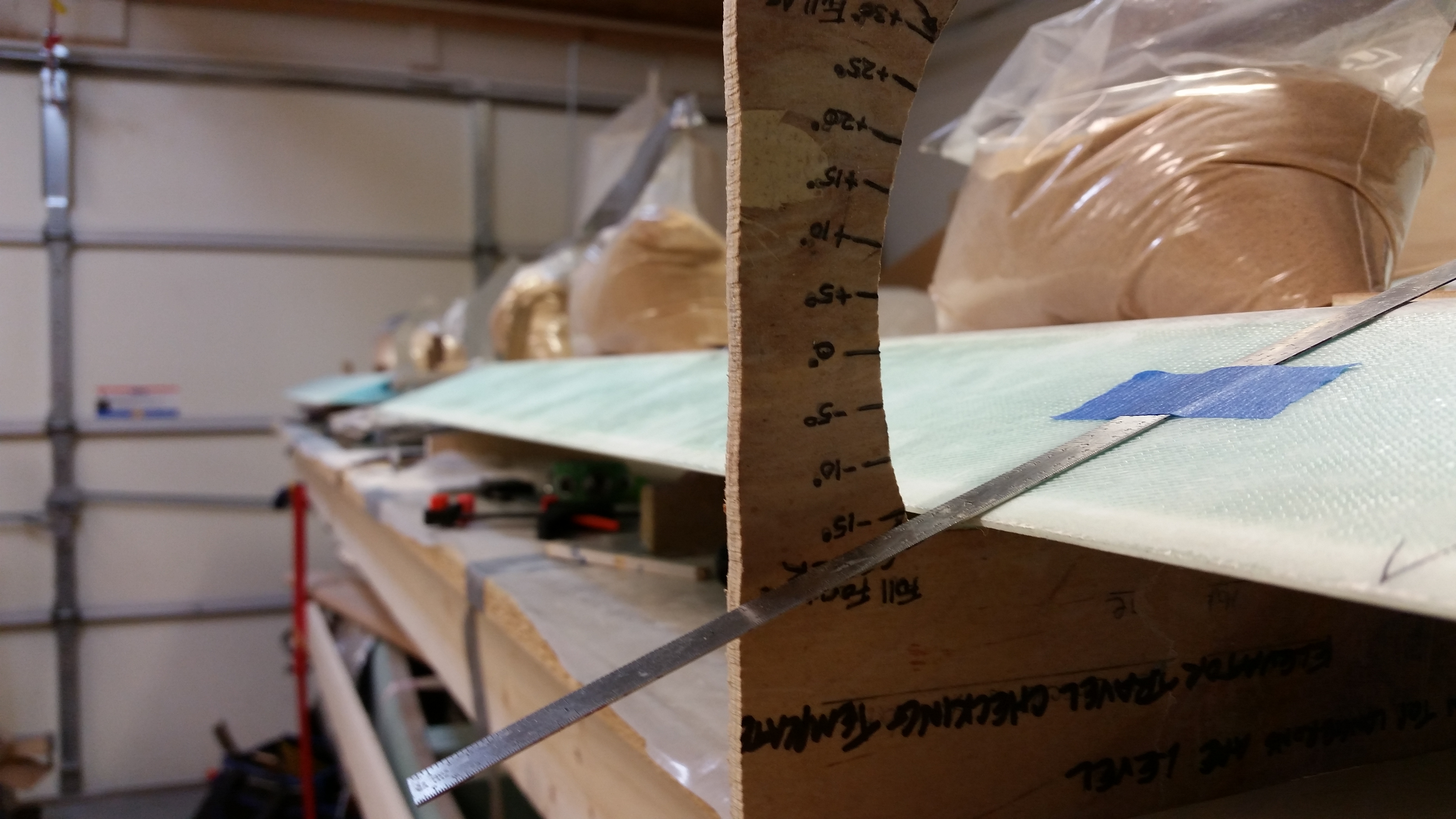
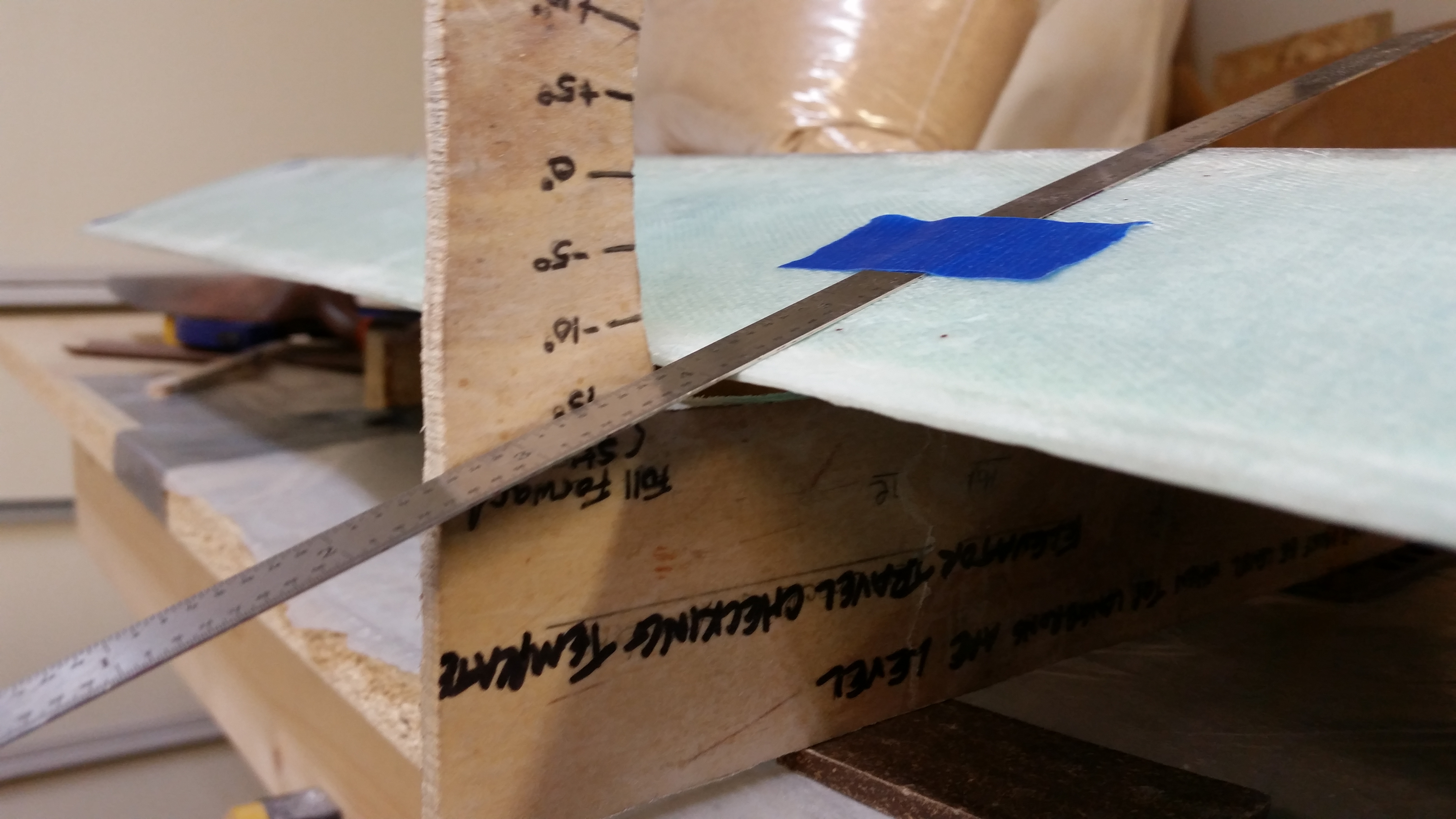
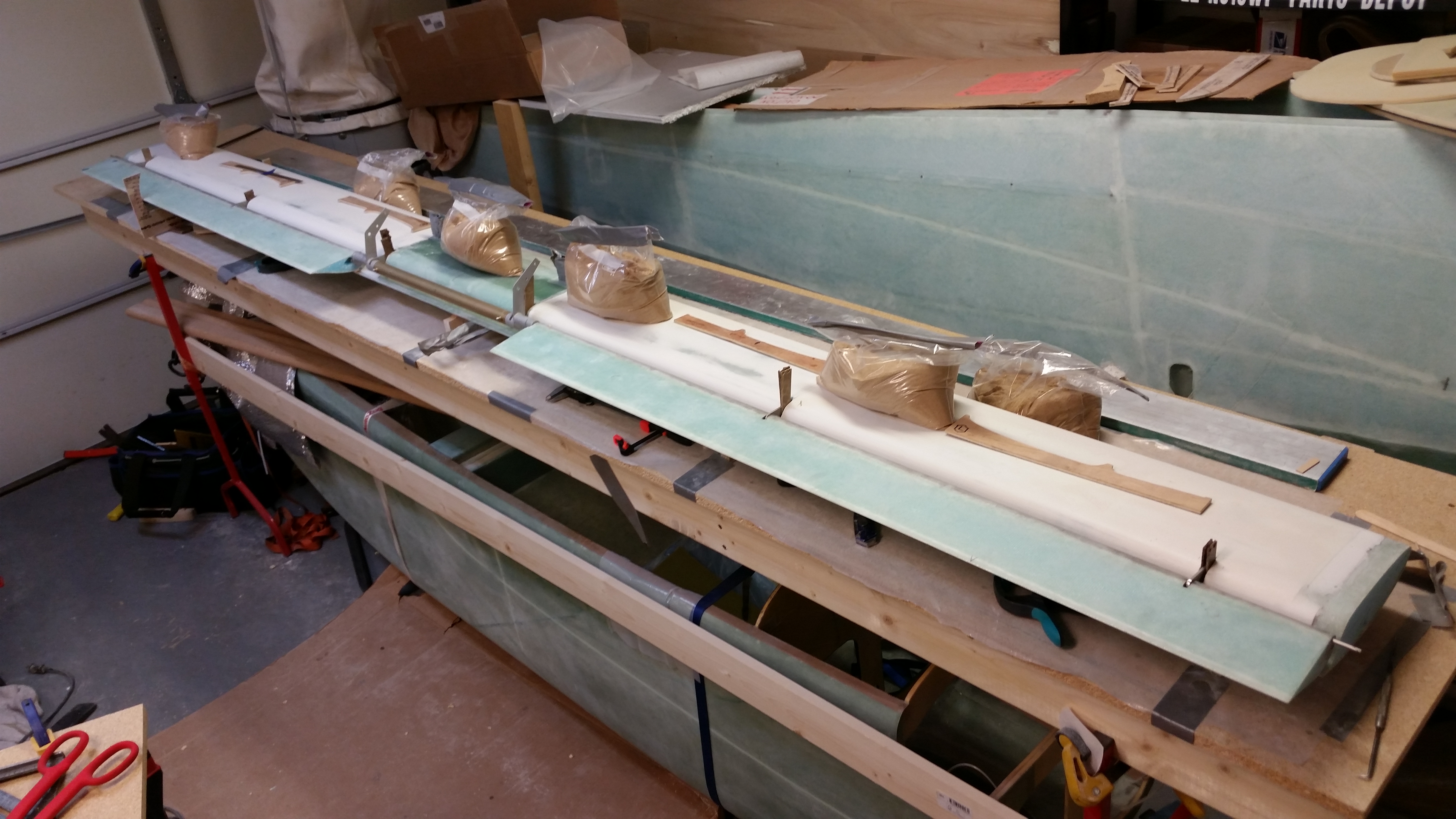
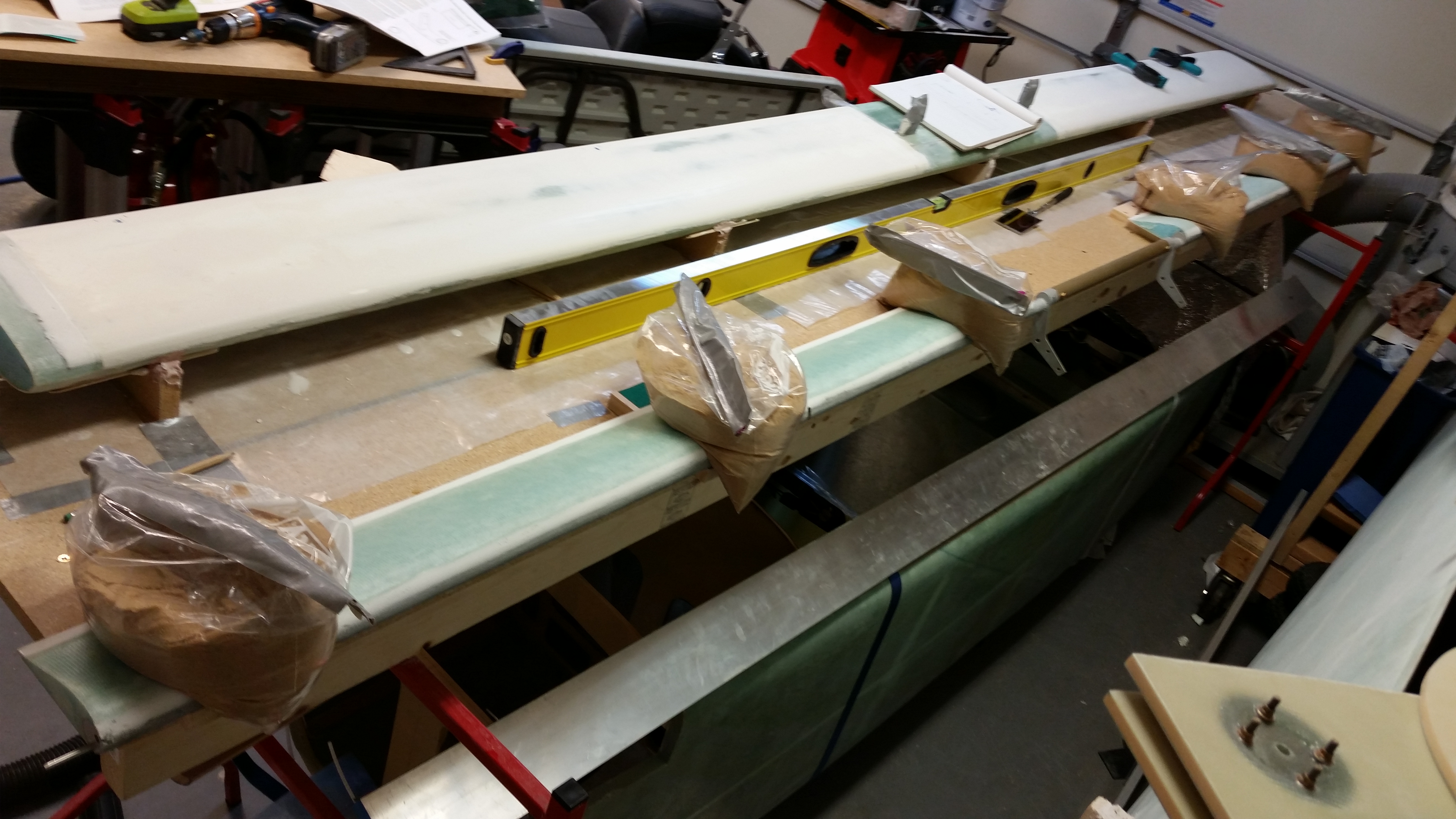
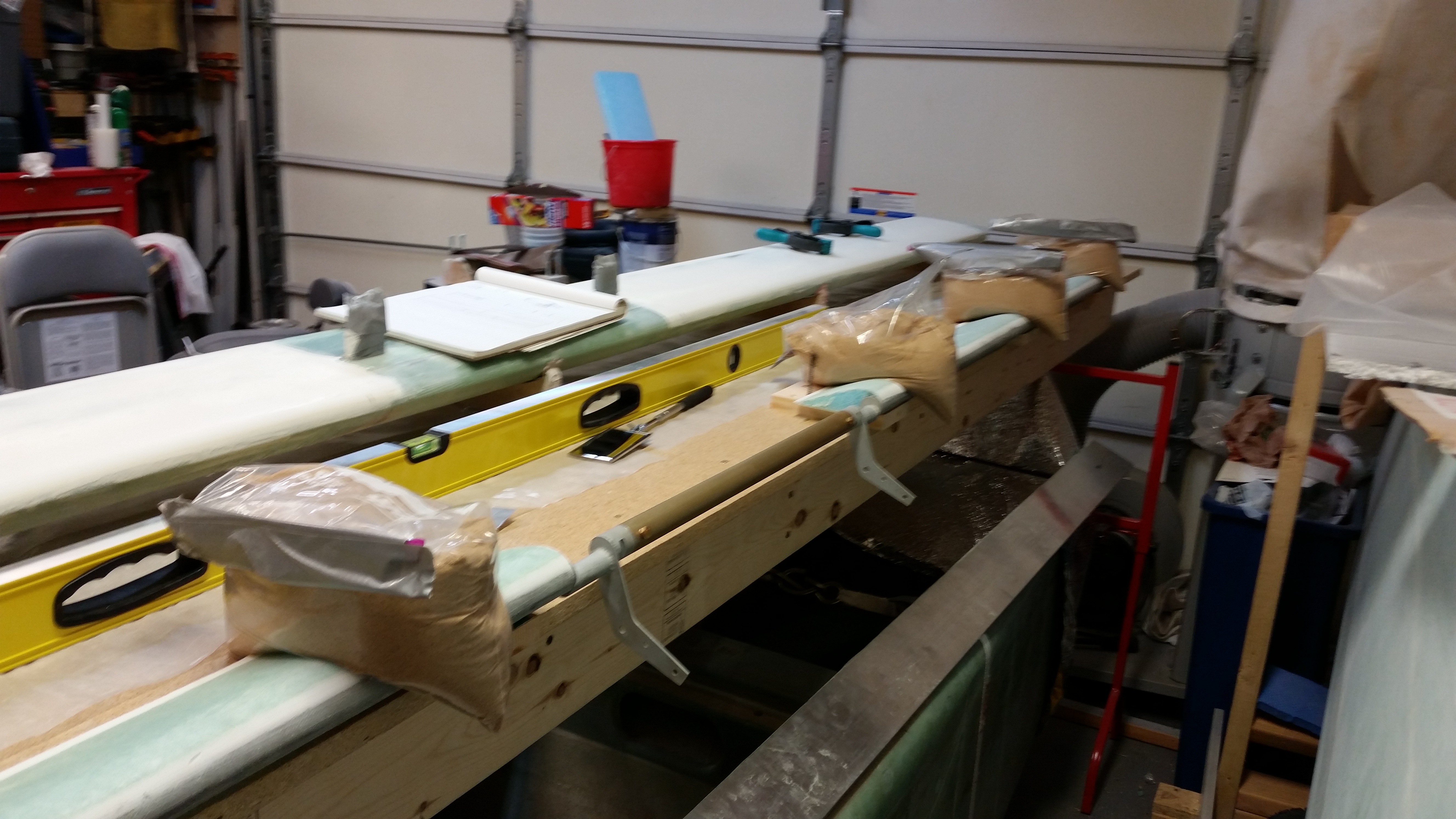
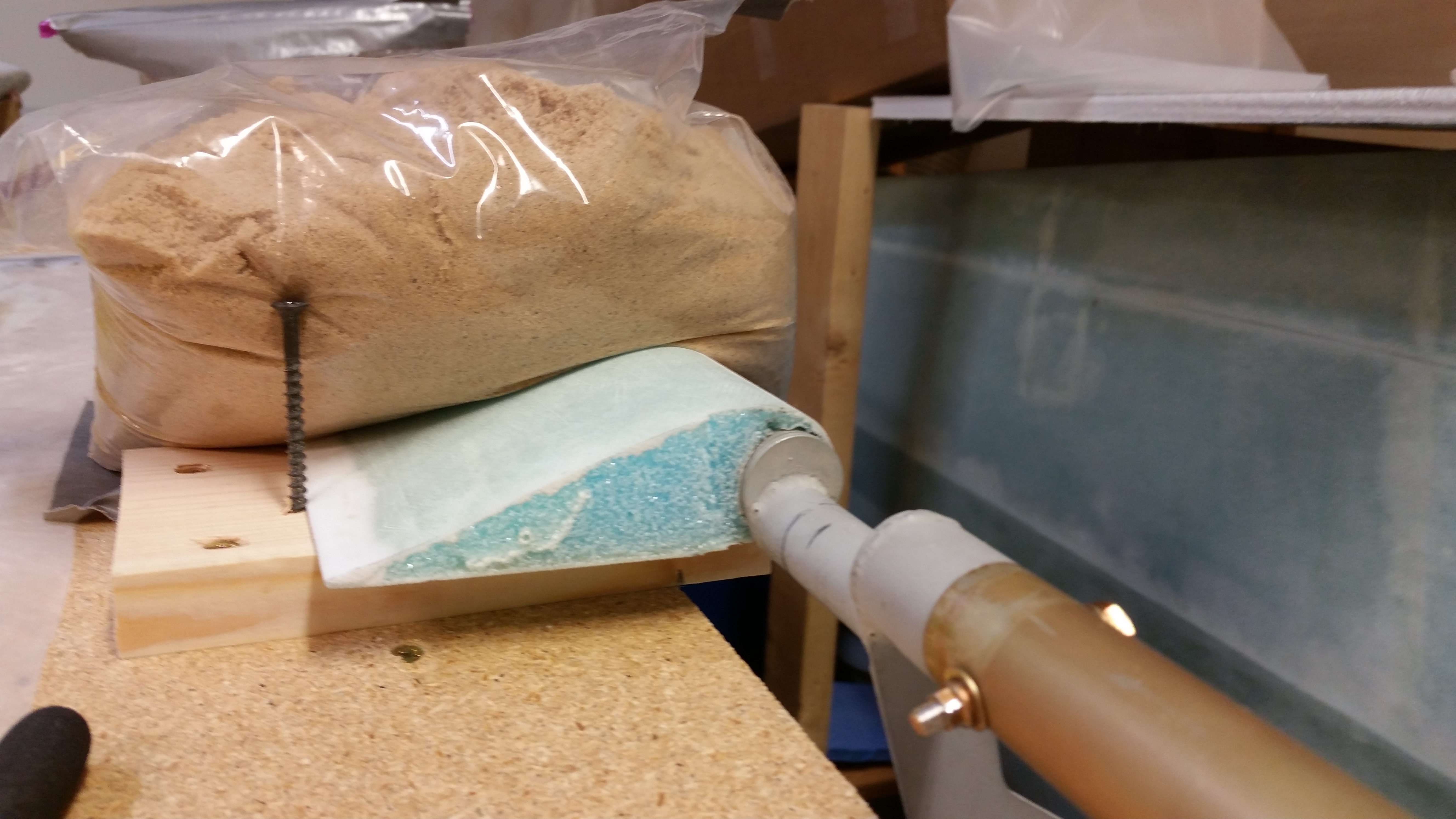
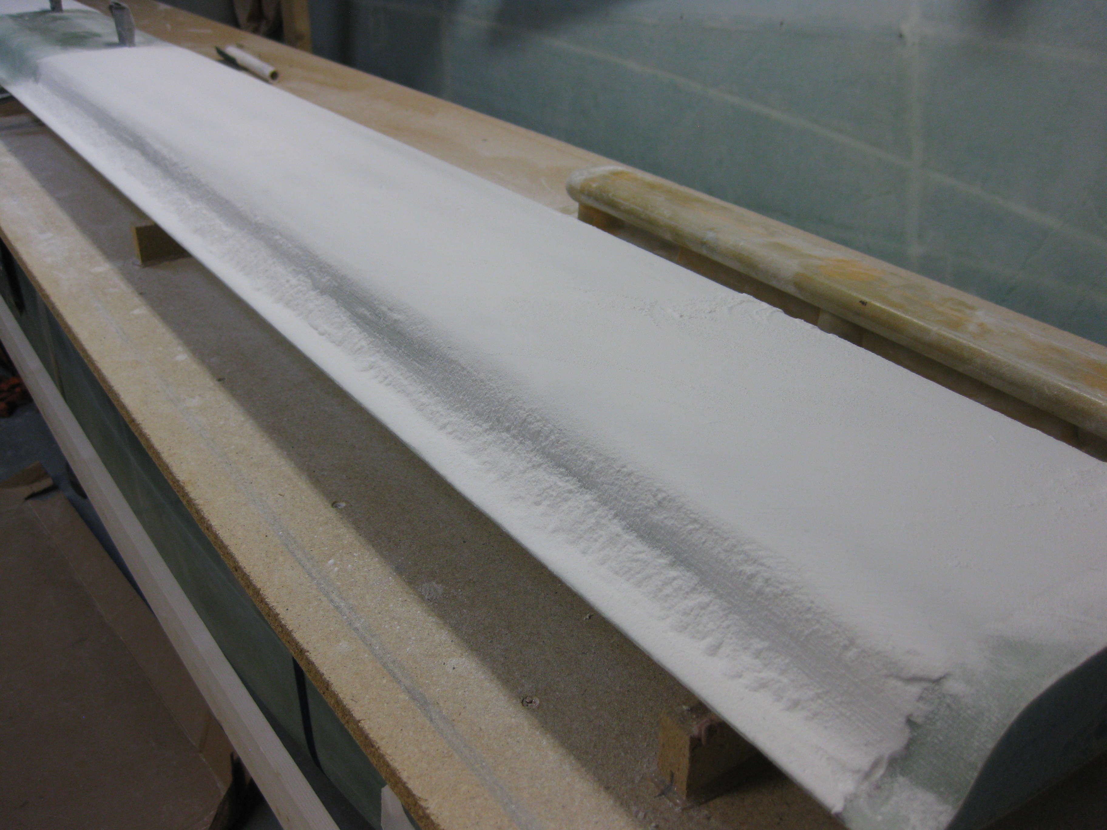
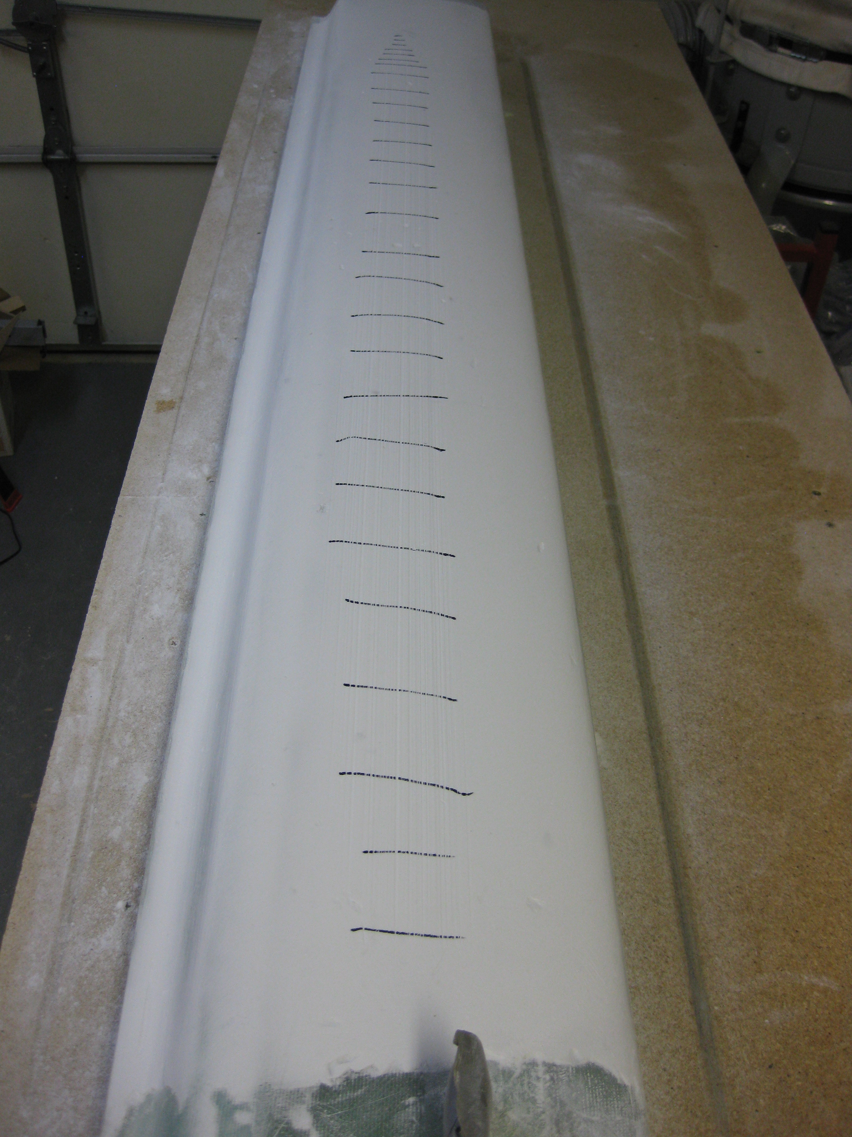
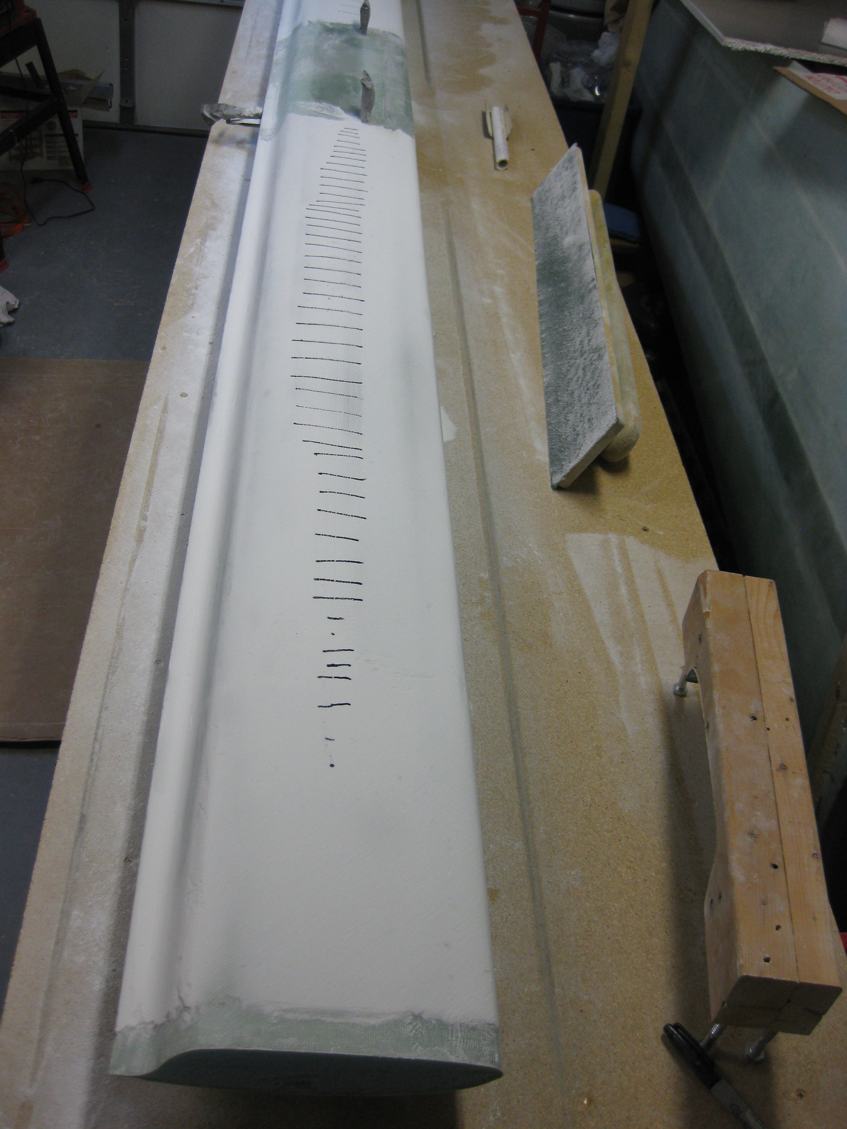
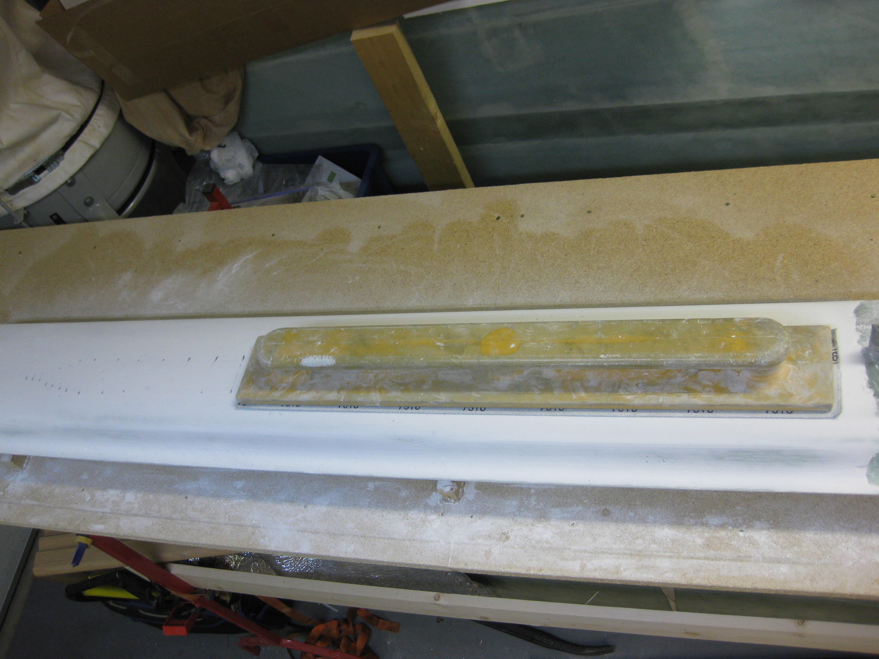
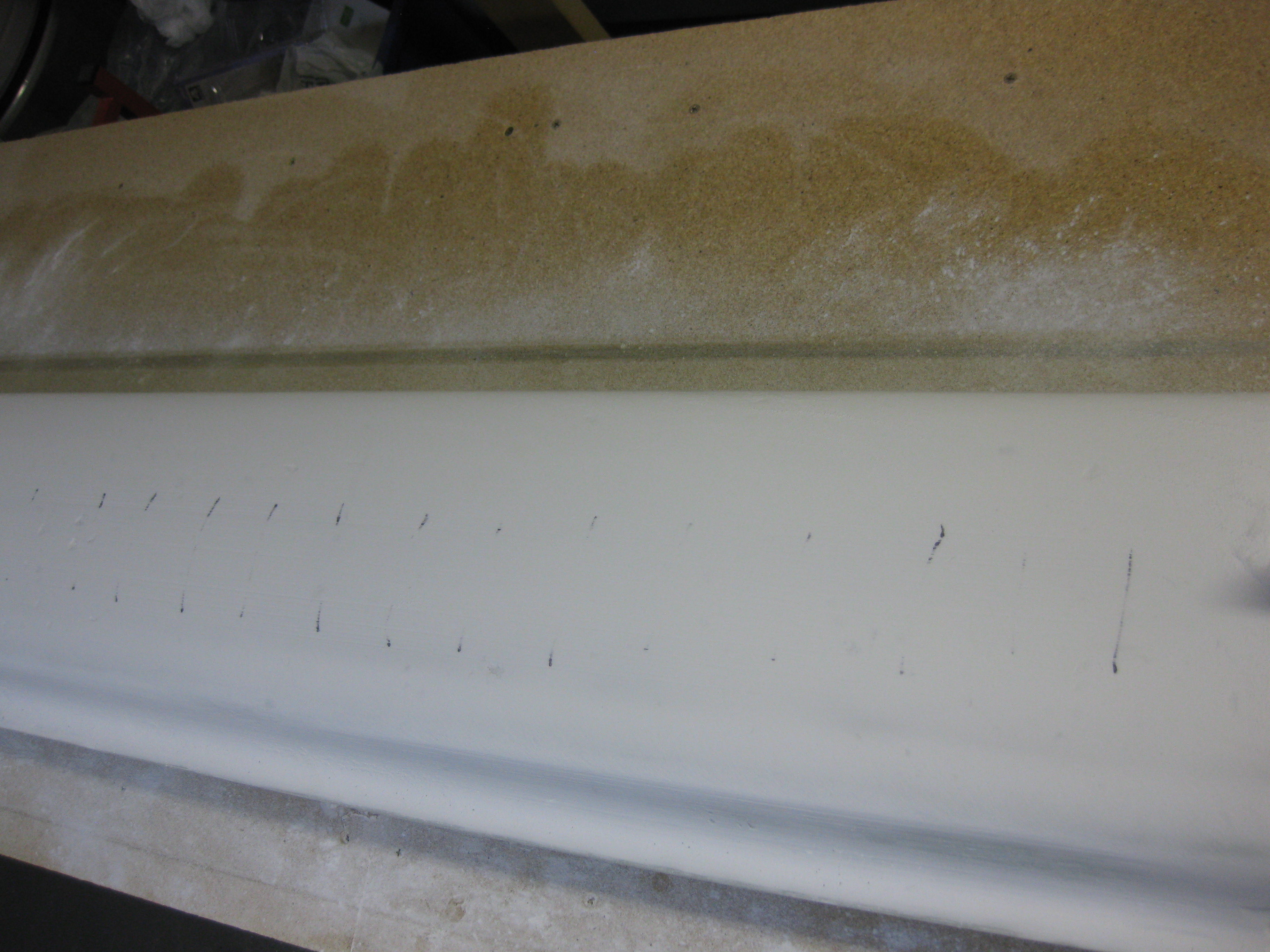
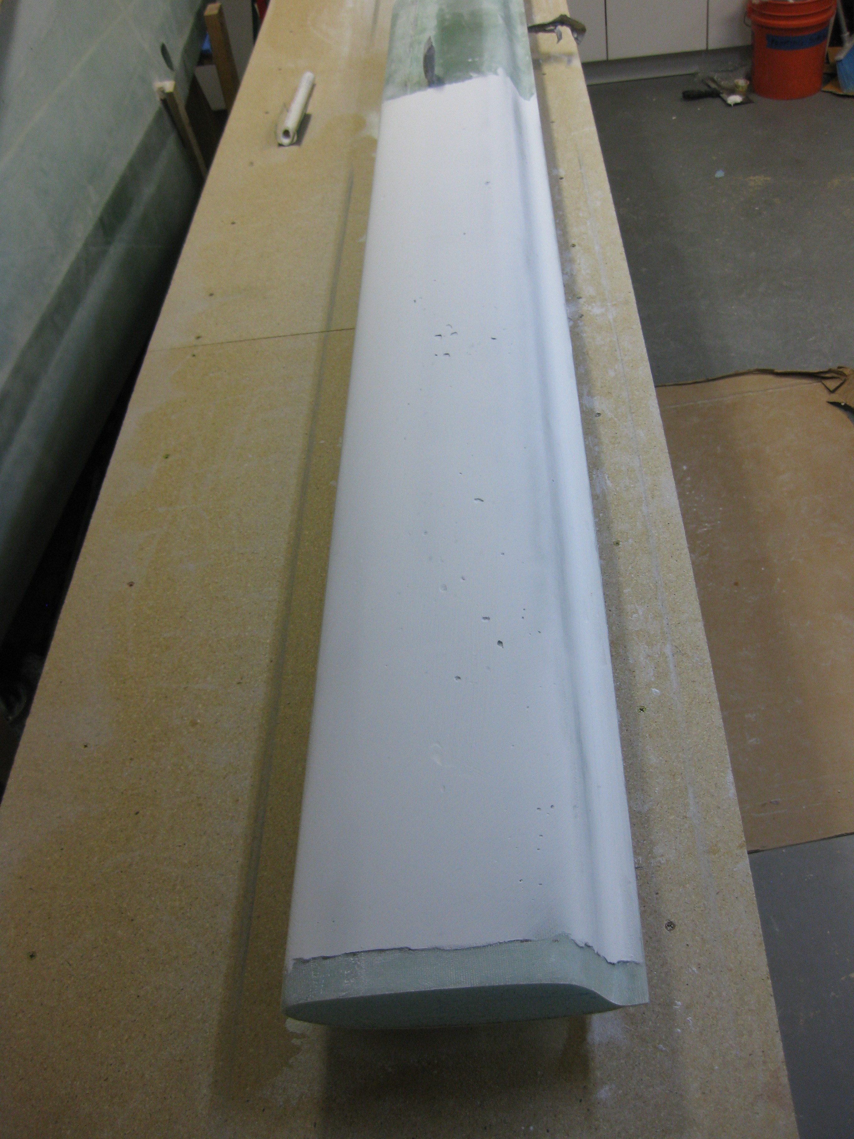
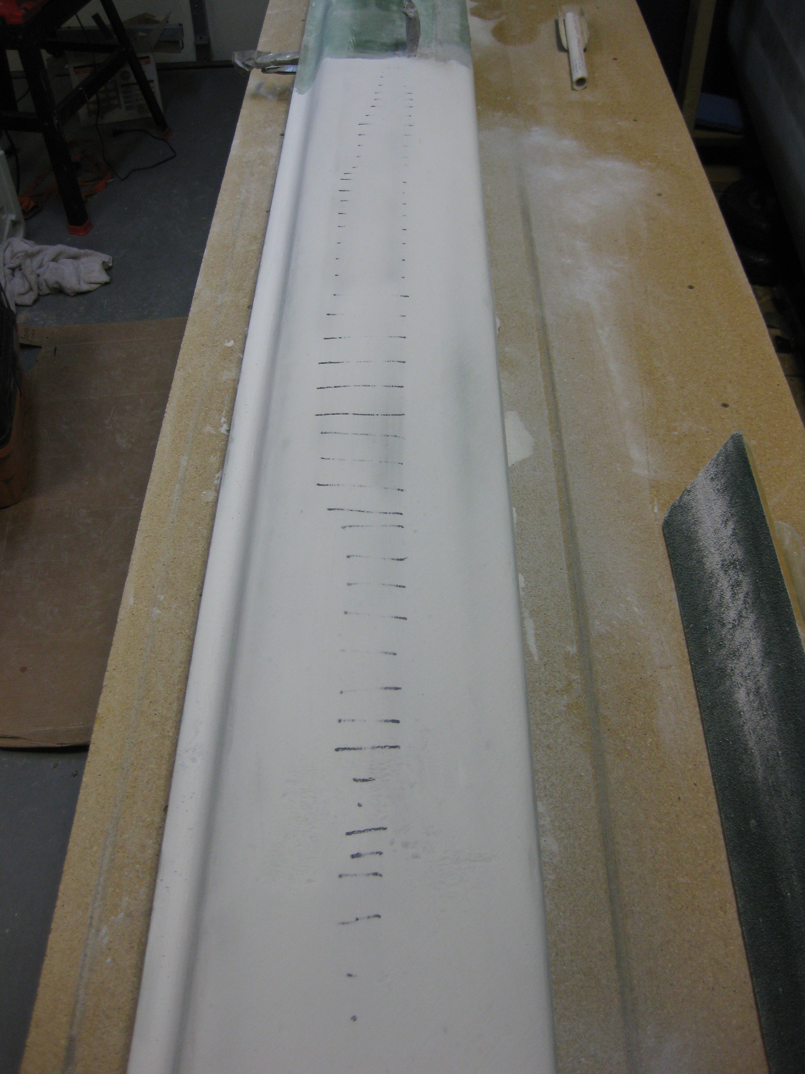
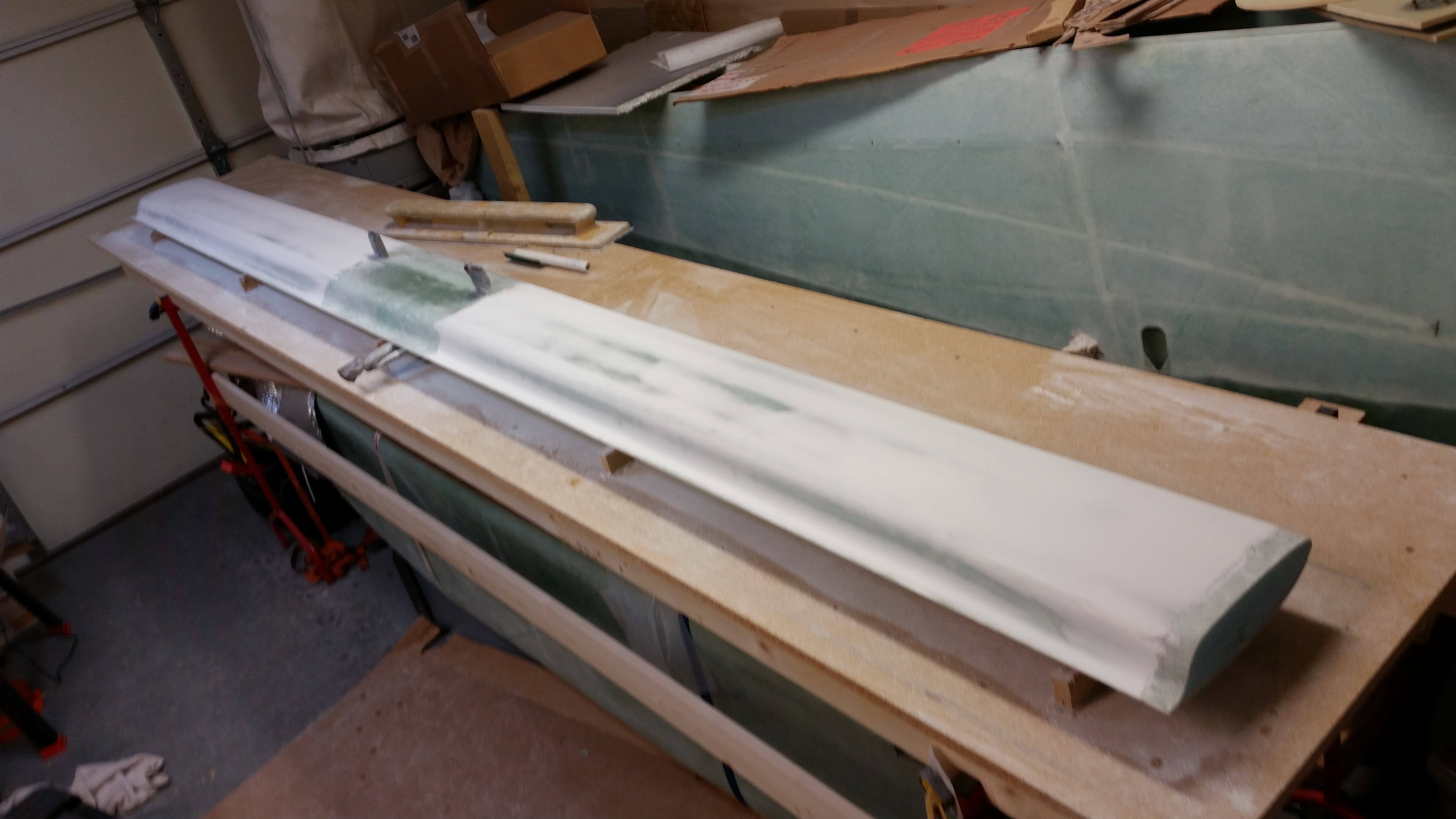
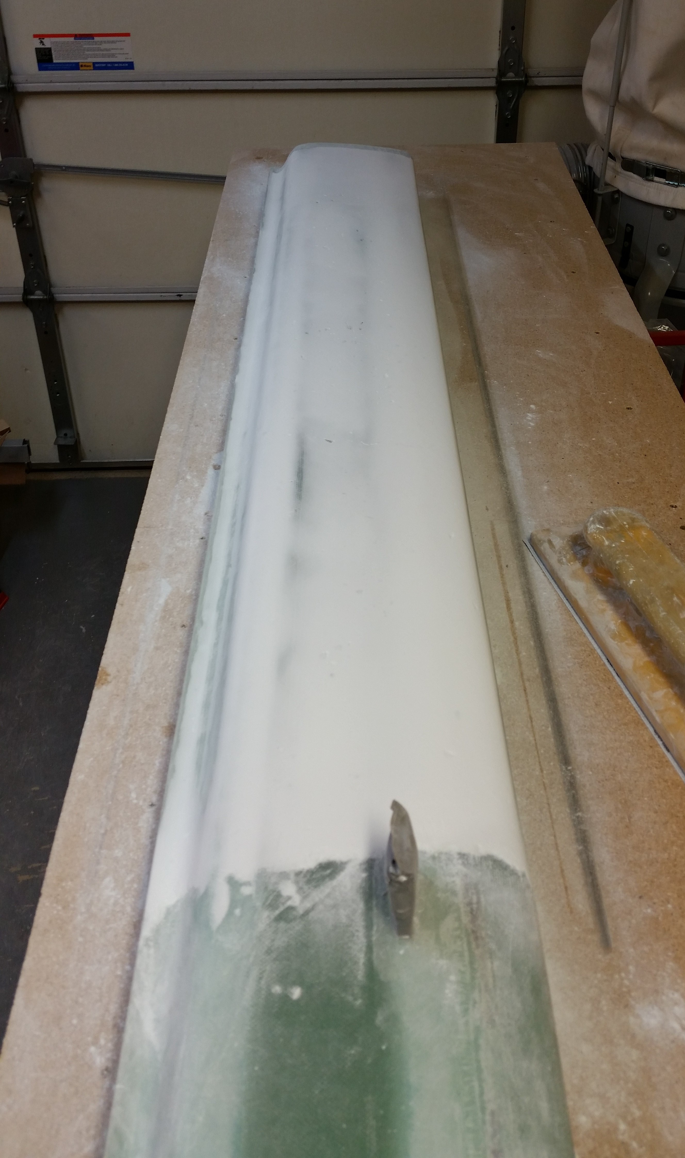
Chapters 10 & 11 – Elevators & Canard Tips

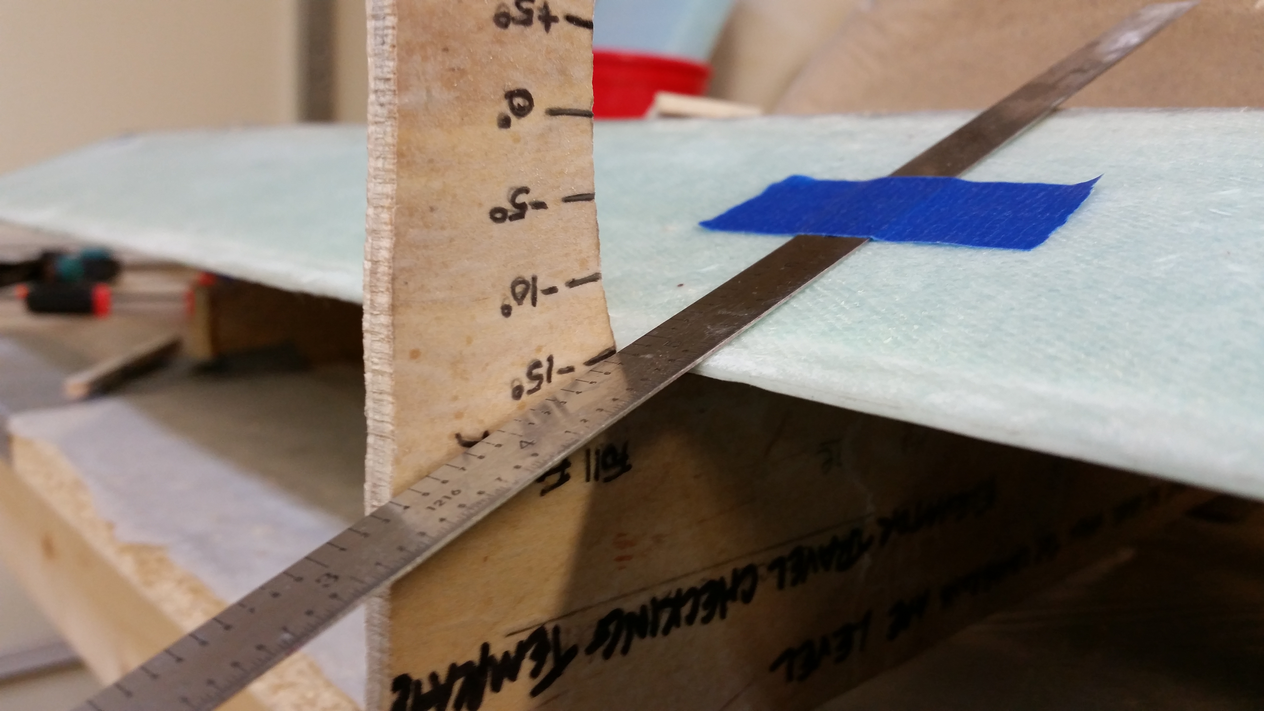
I started today off by checking the elevator travel to ensure it had maintained the 15° up travel that I had before floxing the remaining 4 hinges.  I’m happy to report that not only am I still getting the 15° elevator up travel, but it’s better than when I started installing the elevators.  Success!

Final read: L up elevator - 15+ degreesFinal read: R up elevator - 15+ degrees

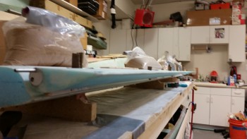
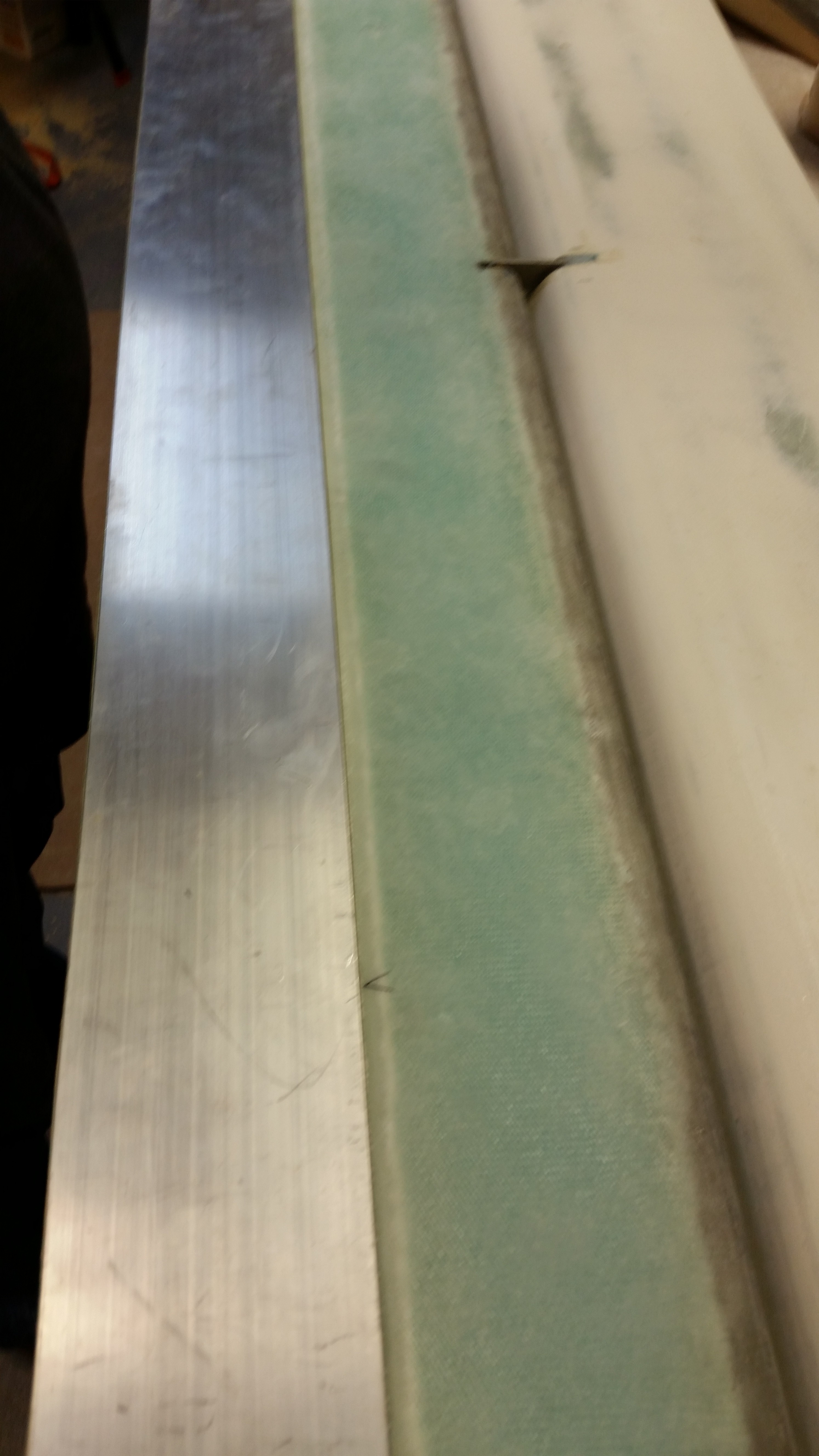
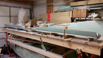
I then double checked the TE of the elevators to ensure that they are even across the entire span of both elevators.  They are… so success again!  (It was difficult to get a full shot of this, but I tried).

Aligning elevators' TE

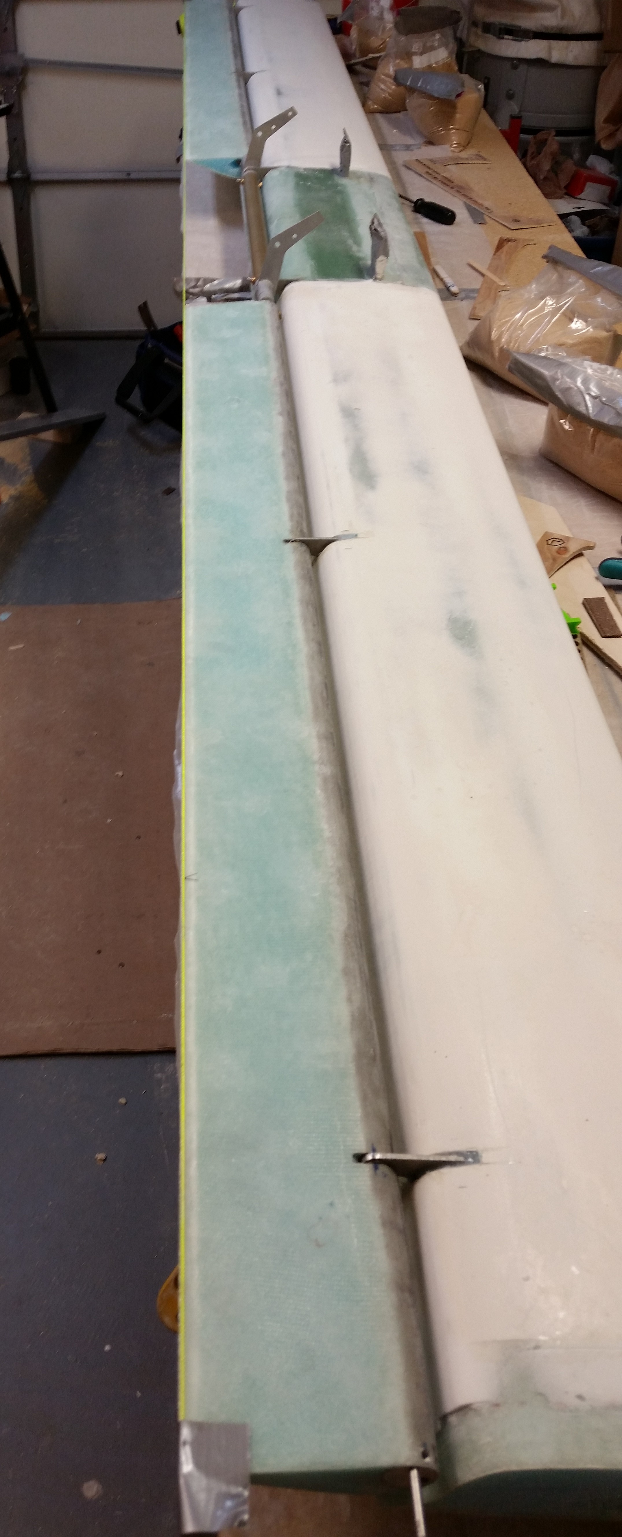
To better show the TE alignment and to check the difference in elevation (this would be viewing the TE at eye level immediately behind it, looking that both left & right elevators align in the height and are straight across… versus above which is assessing the TE alignment from straight above) I ran a yellow string.  It all looked good.

String on TE

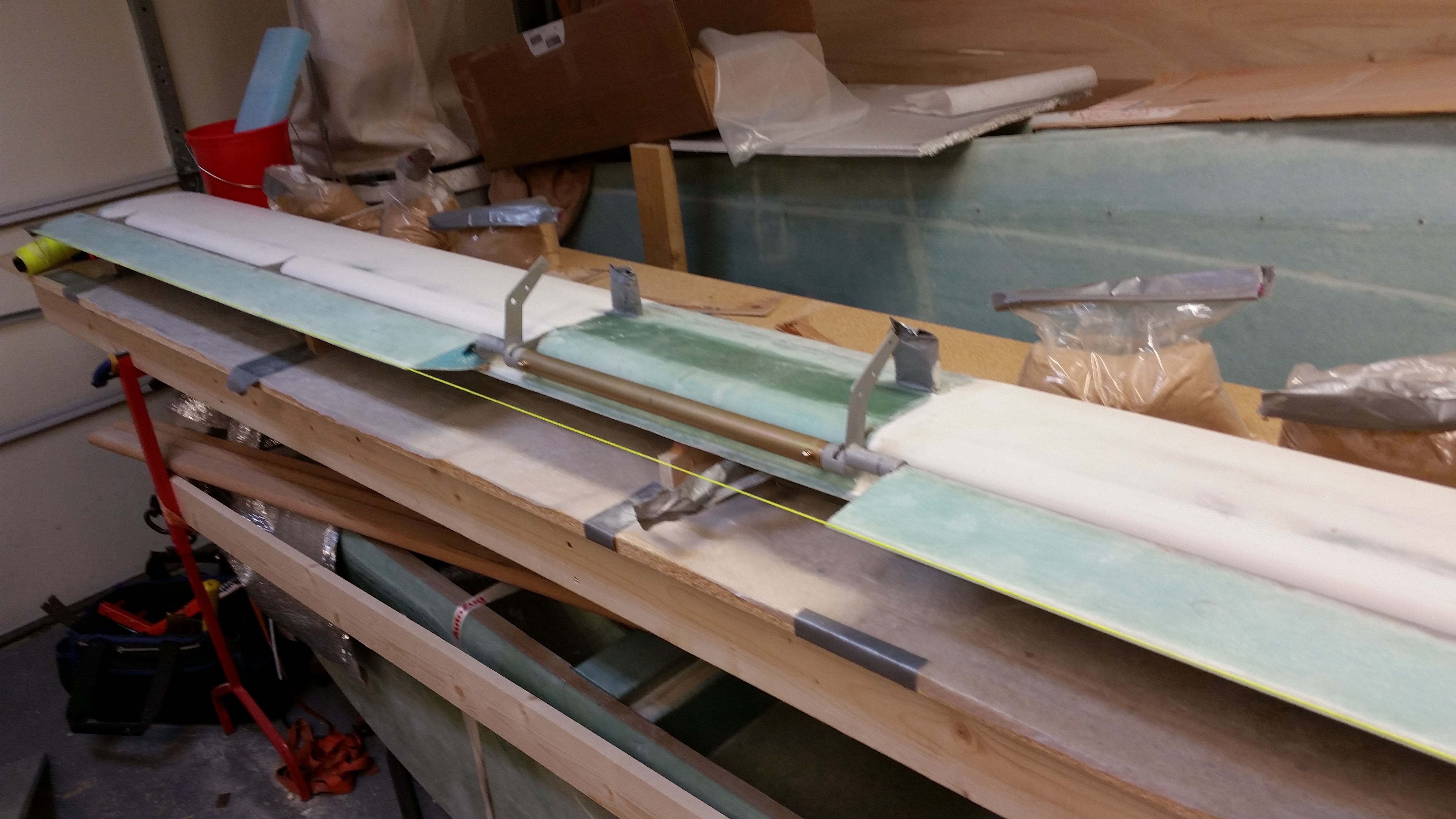
Here’s another shot of my “stringing” the elevators’ TE.

"Stringing" TE

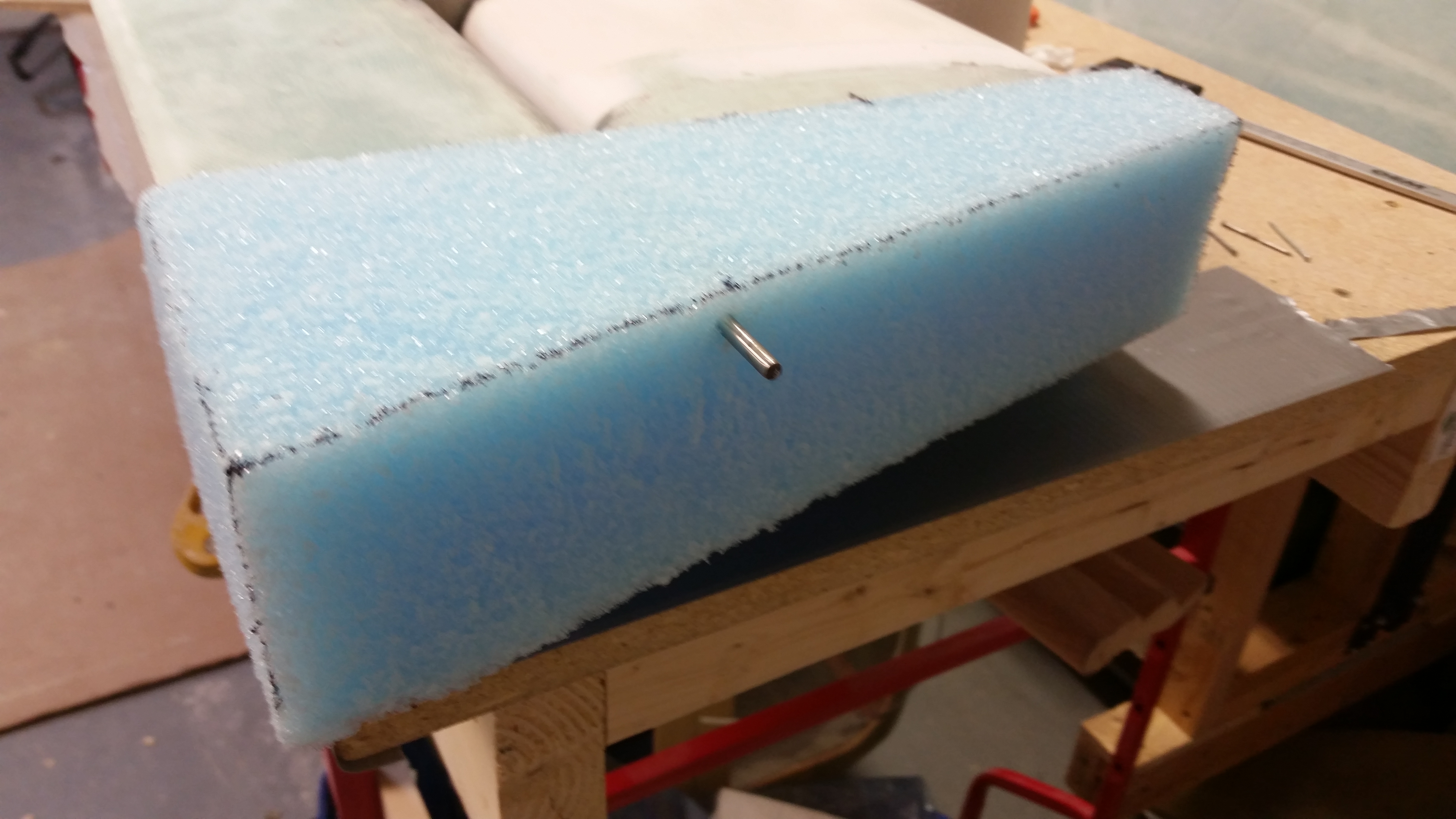
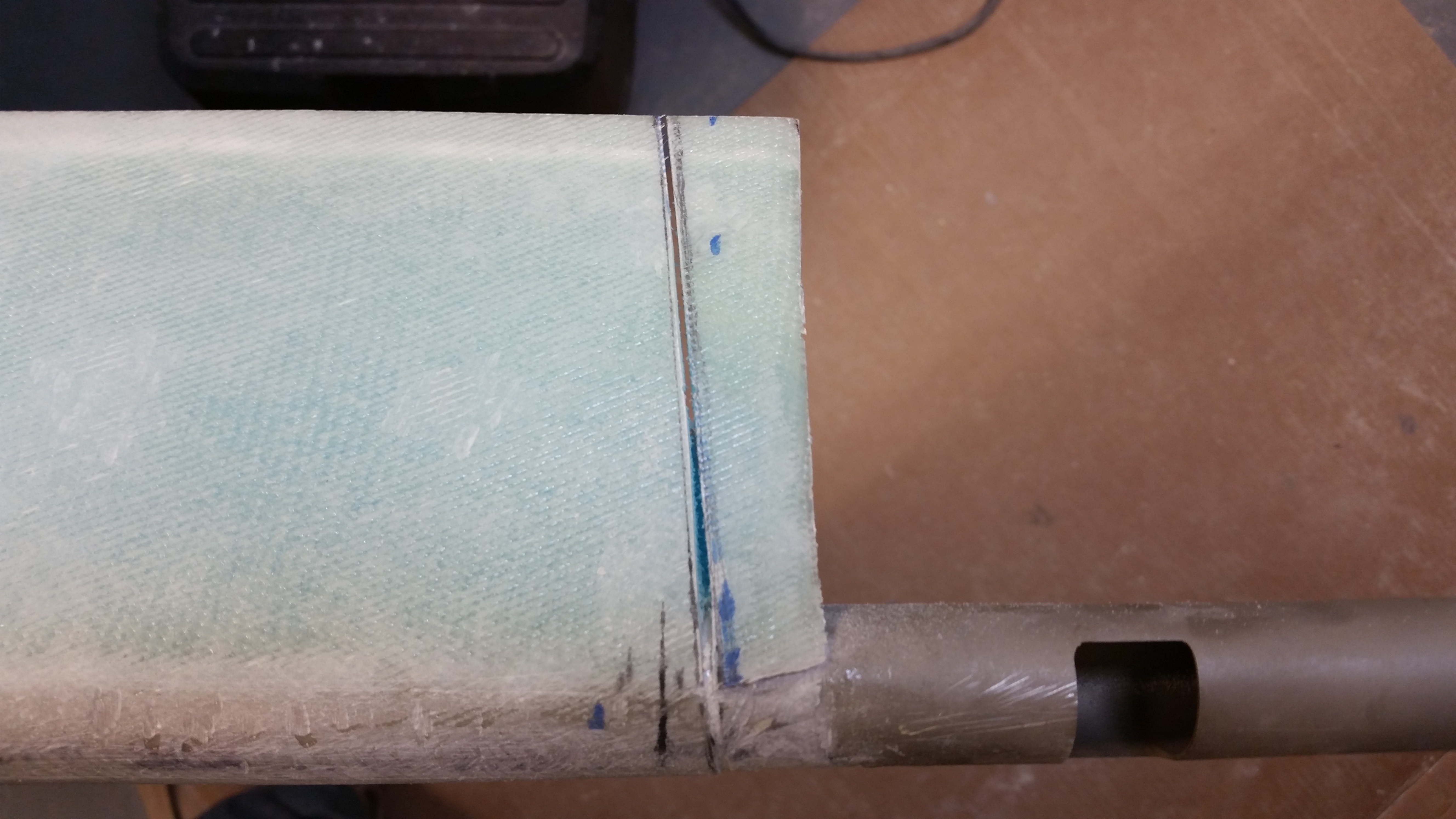
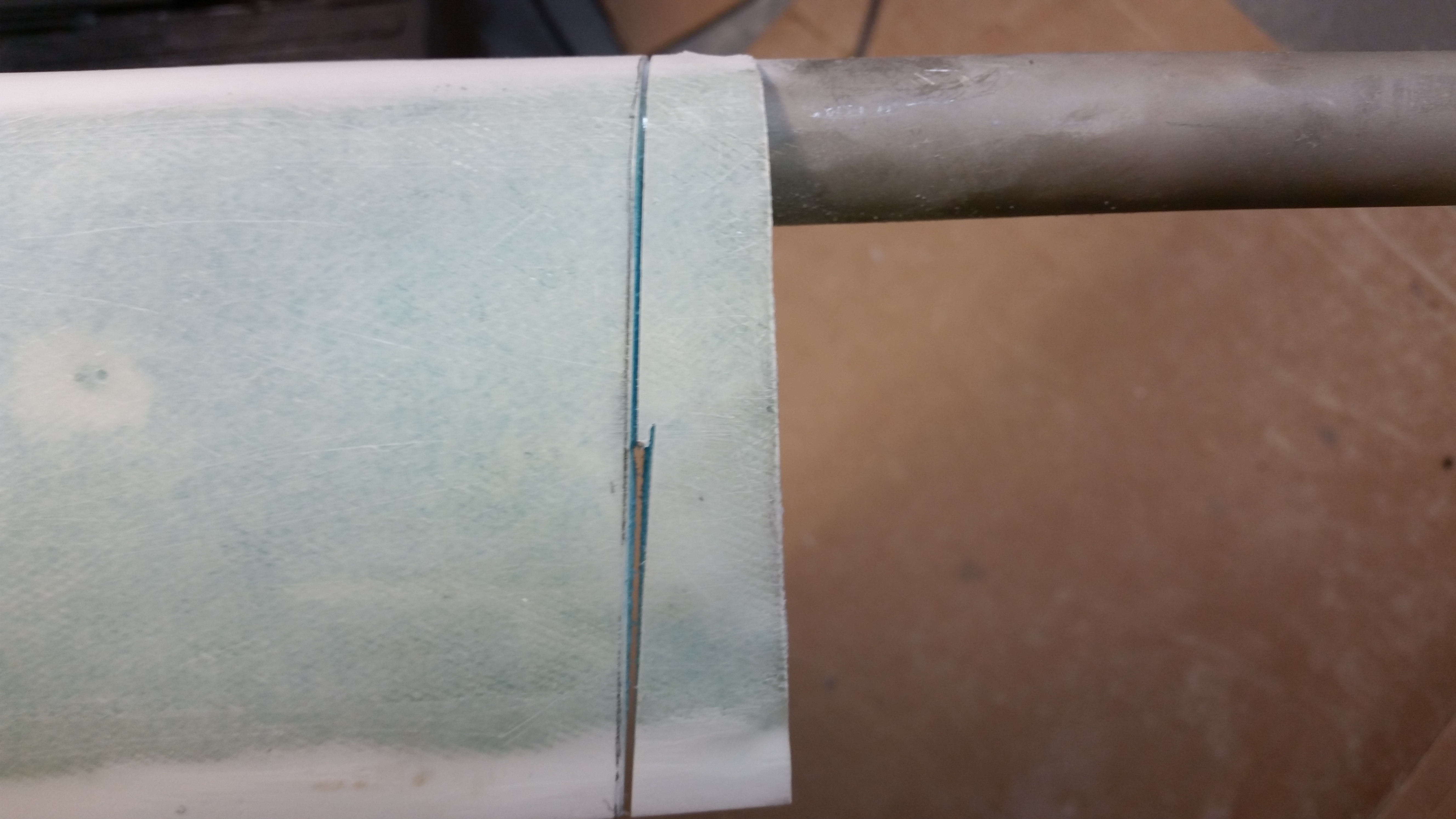
With the elevators good I started the process of attaching the blue foam canard tips.  Now, when I hot wired the foam tips one came out a little narrow than the other.  With my canard TE just a bit straighter (read: higher), it messed with the 1″ dimension that gets measured up from the TE to the upper side of the foam.  On the narrower blue foam wedge I couldn’t squeak out this 1″, so I ended up grabbing a wood handsaw and cutting another blue foam canard end piece.

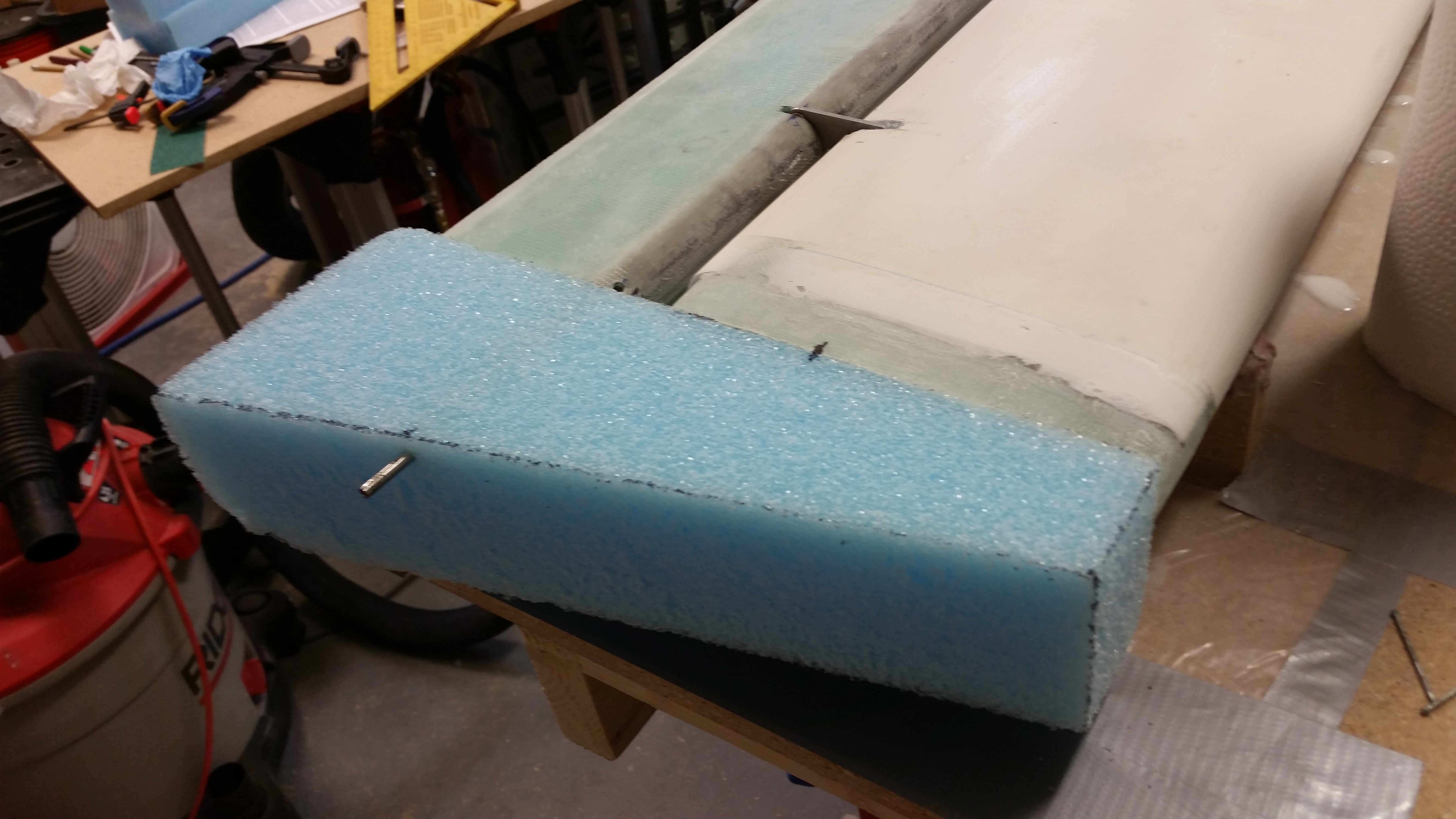
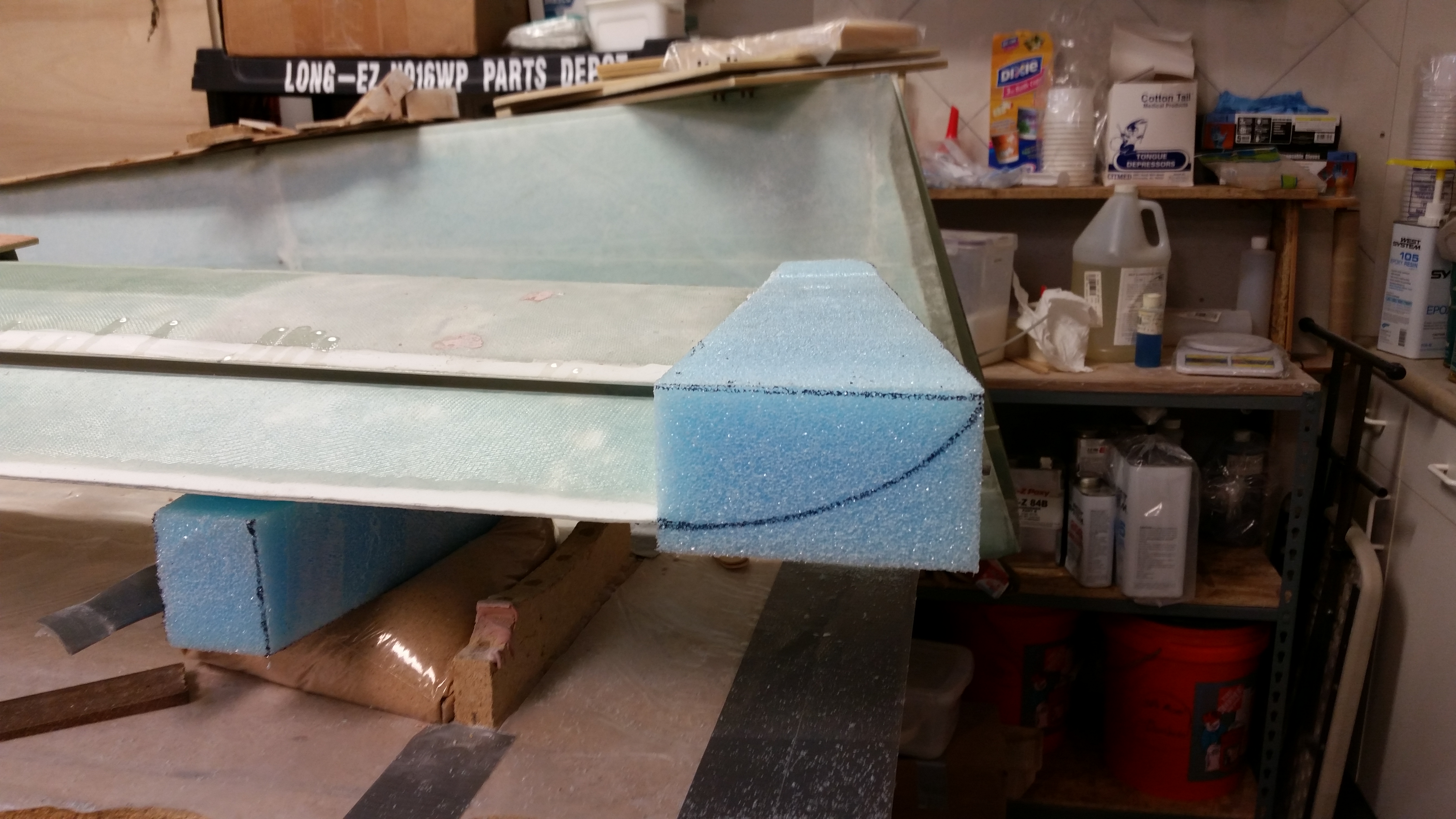
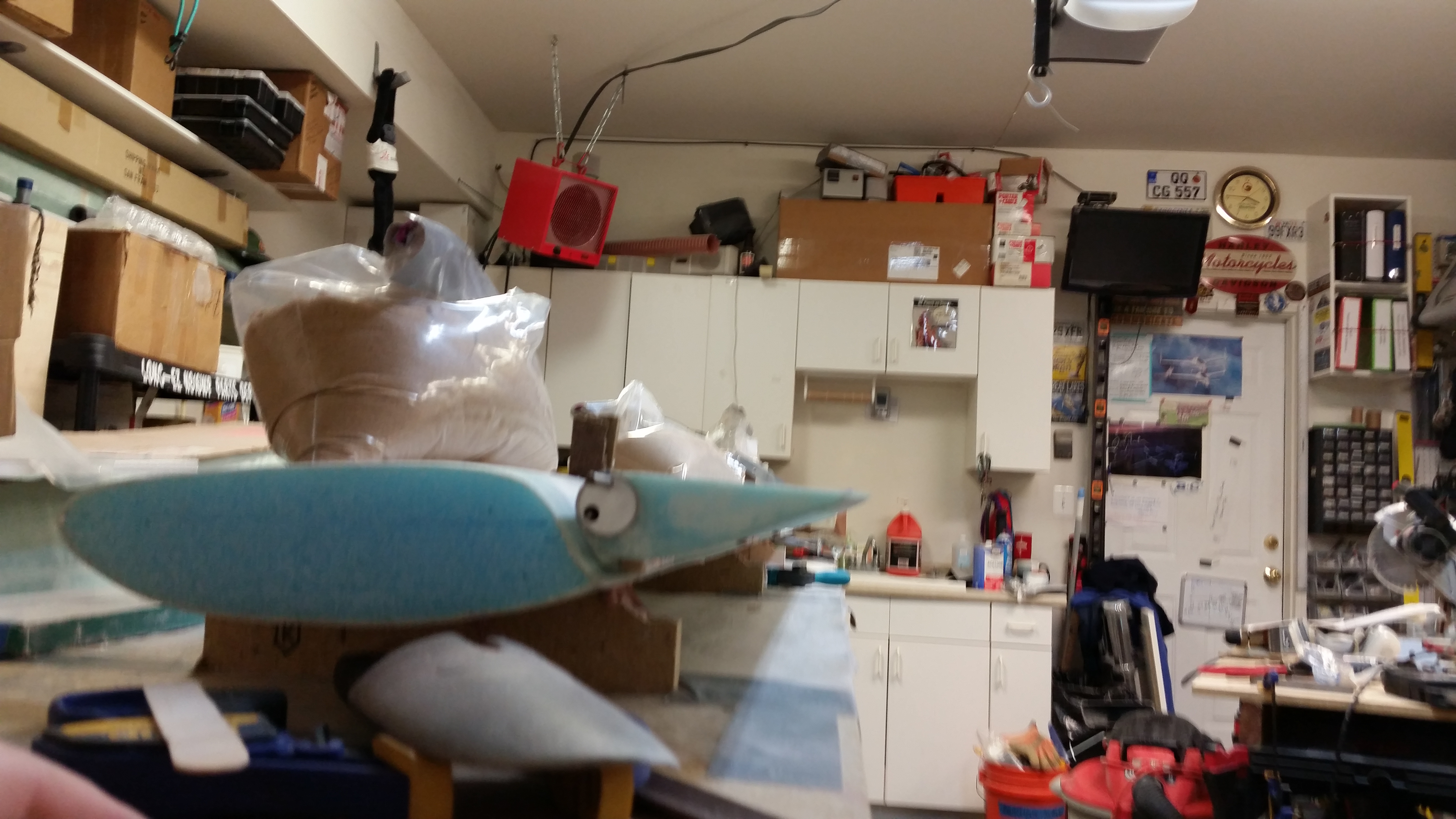
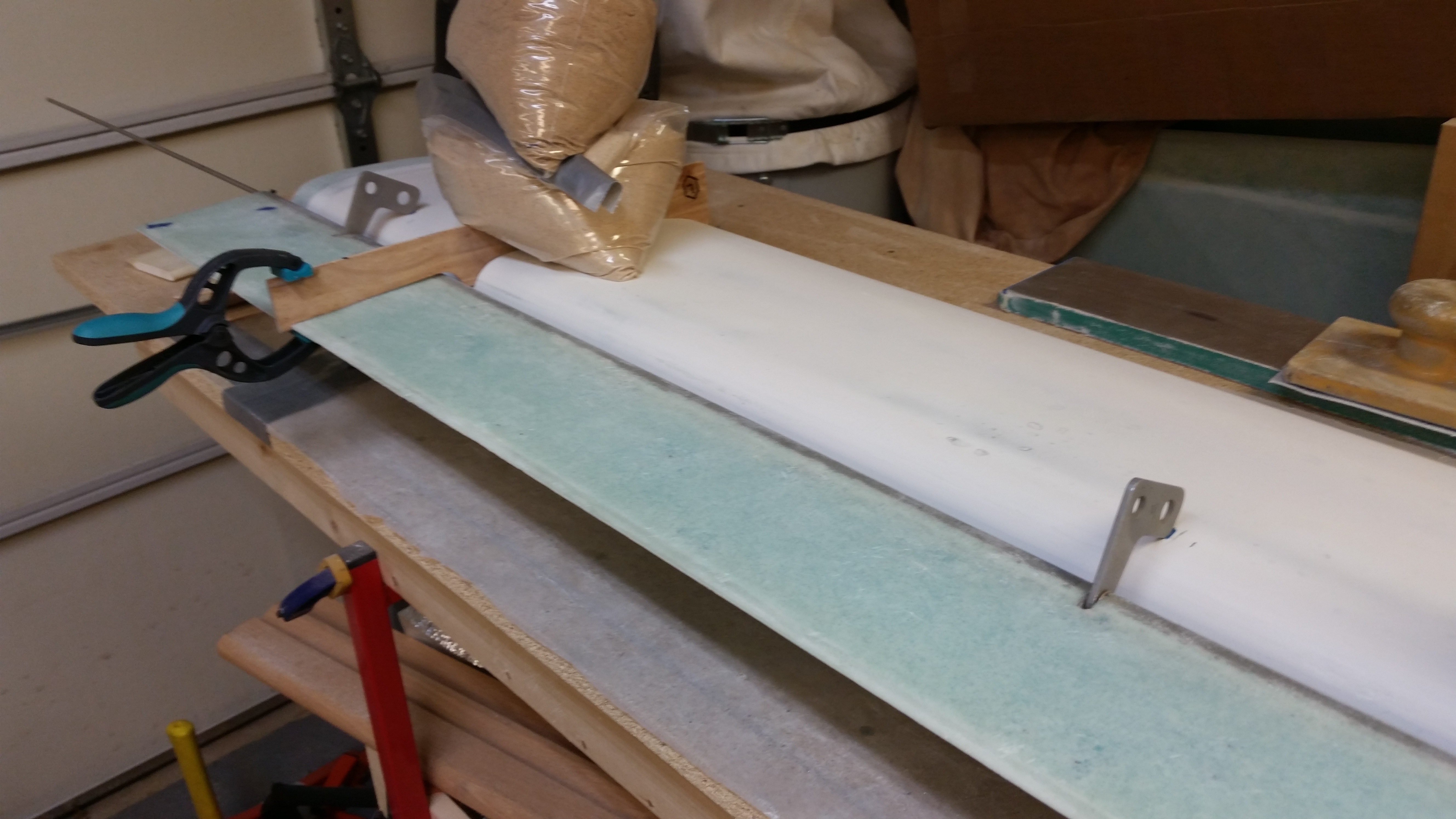
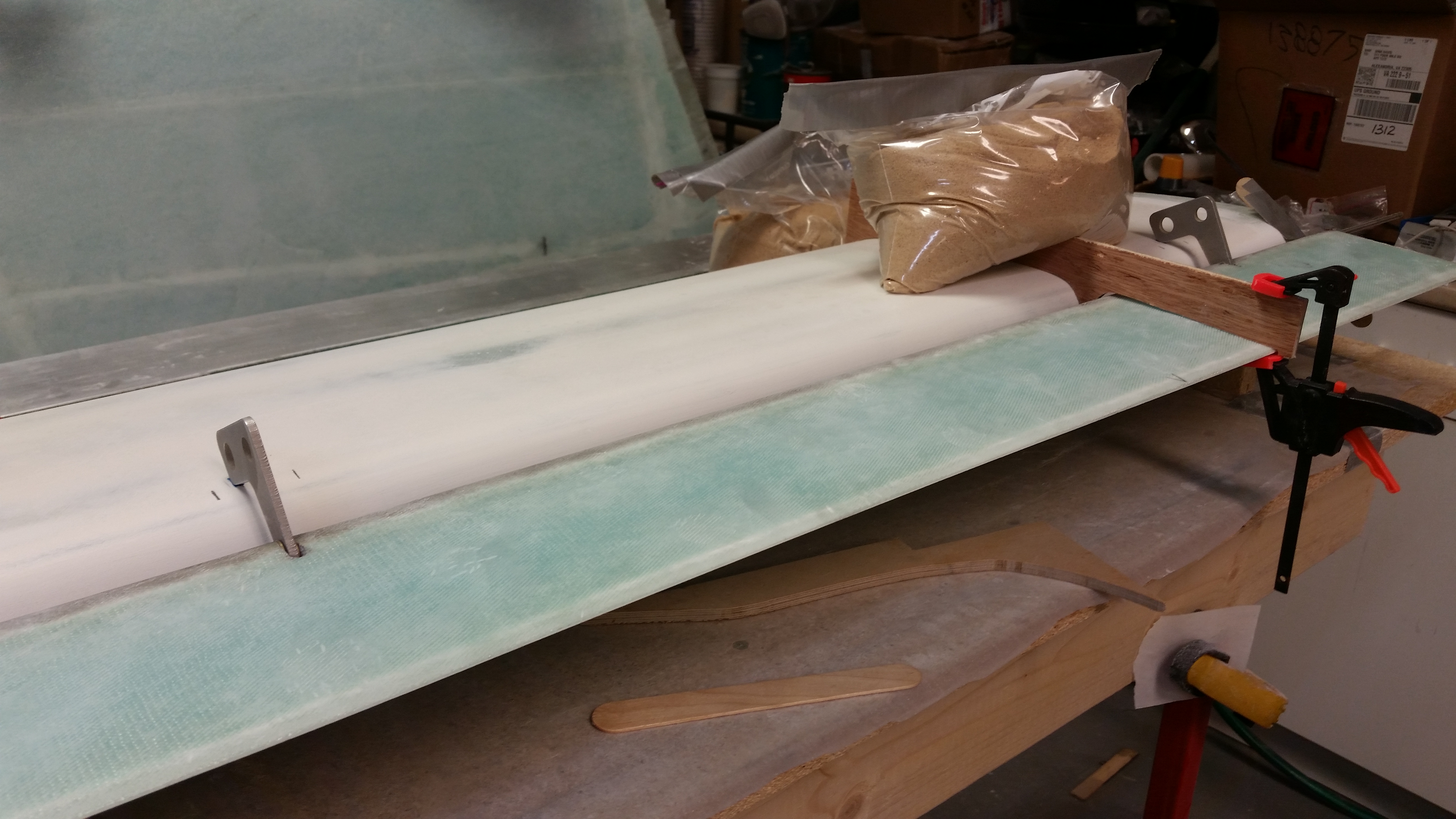
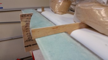
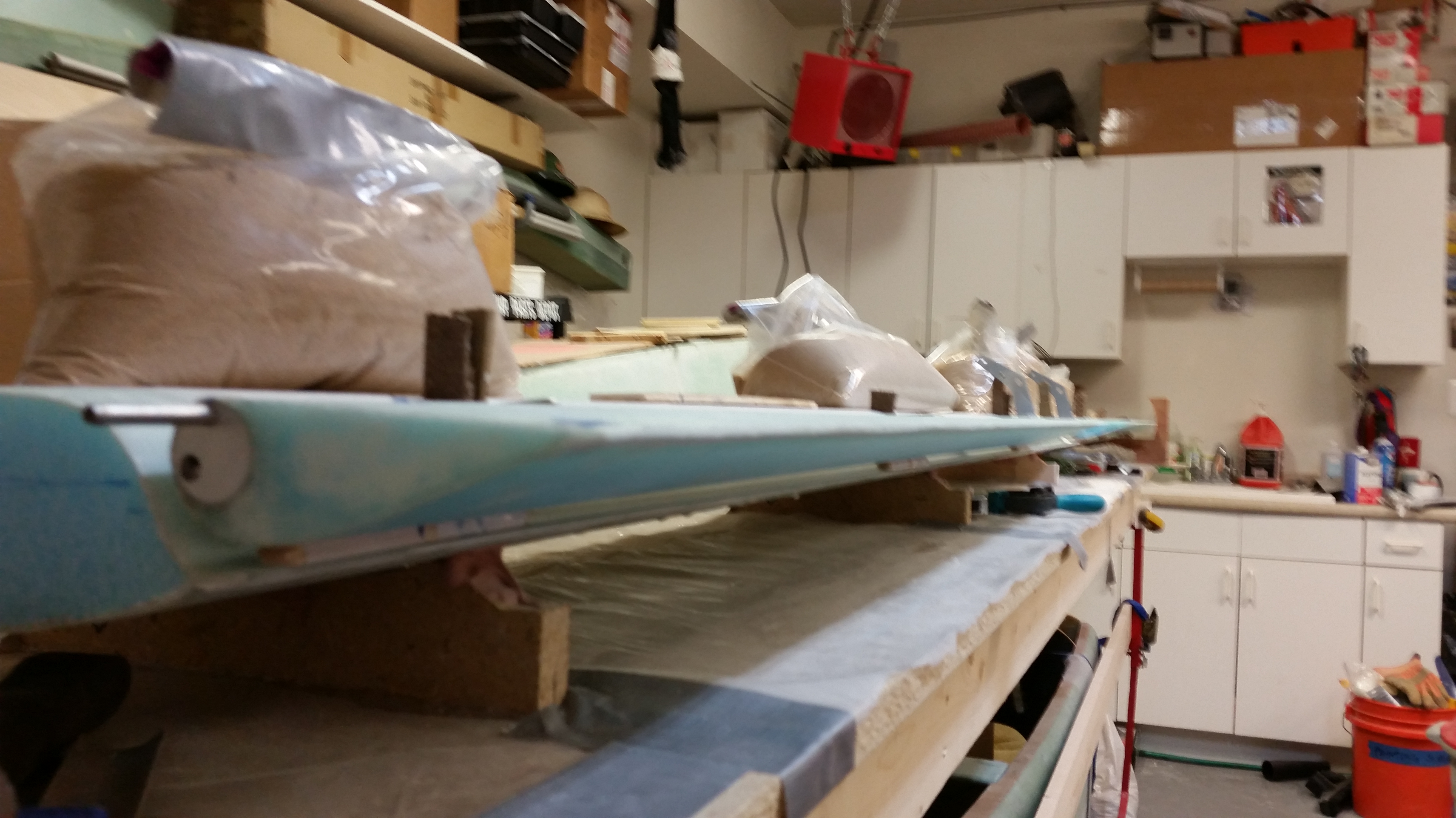
I then temporarily attached a blue foam swoosh tip blank on the left side of the canard with the elevator hinge pin sticking out a couple of inches.  I noted that I had over 1″ to work with above the canard TE and ensured that my spacing was good.

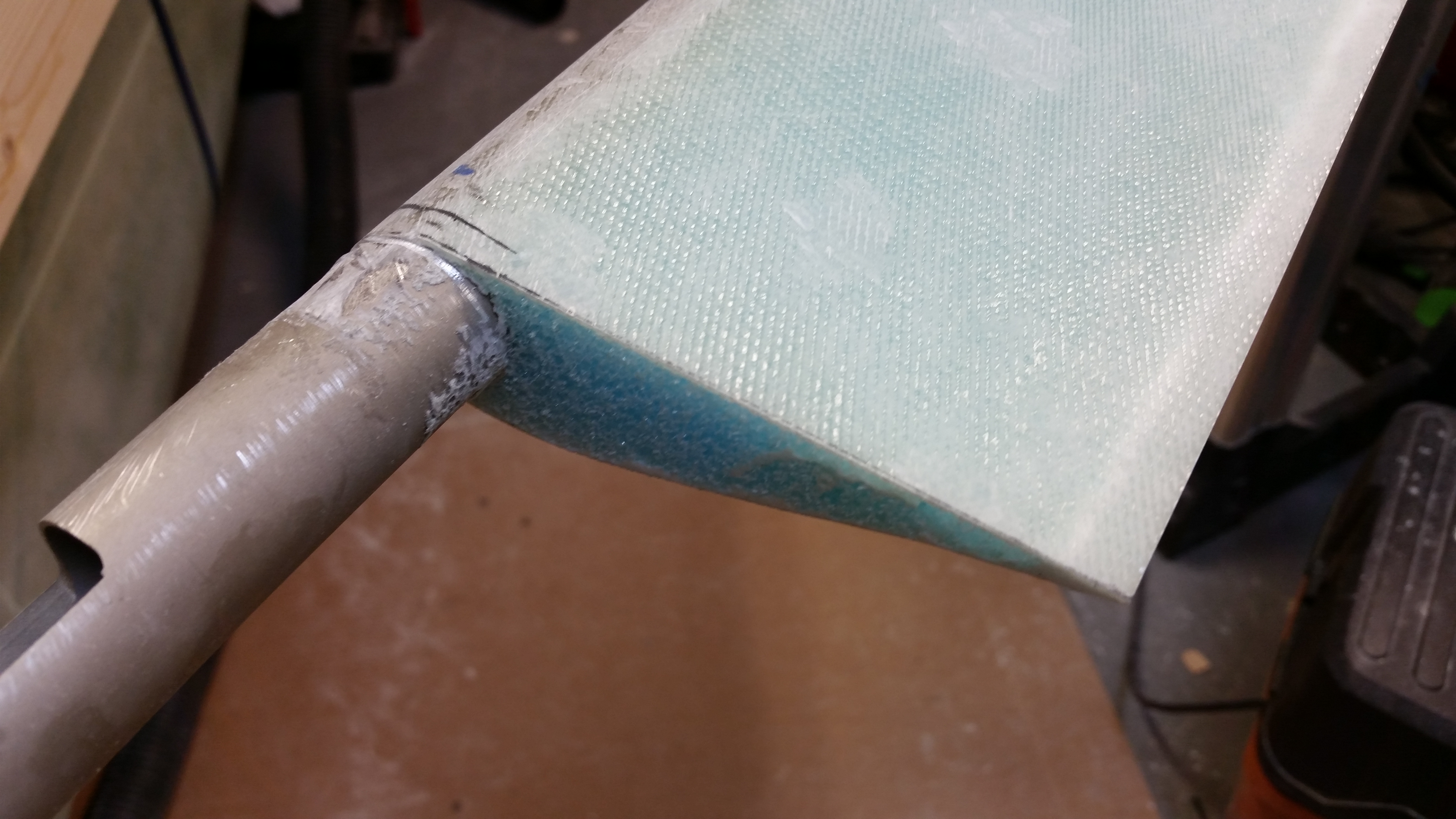
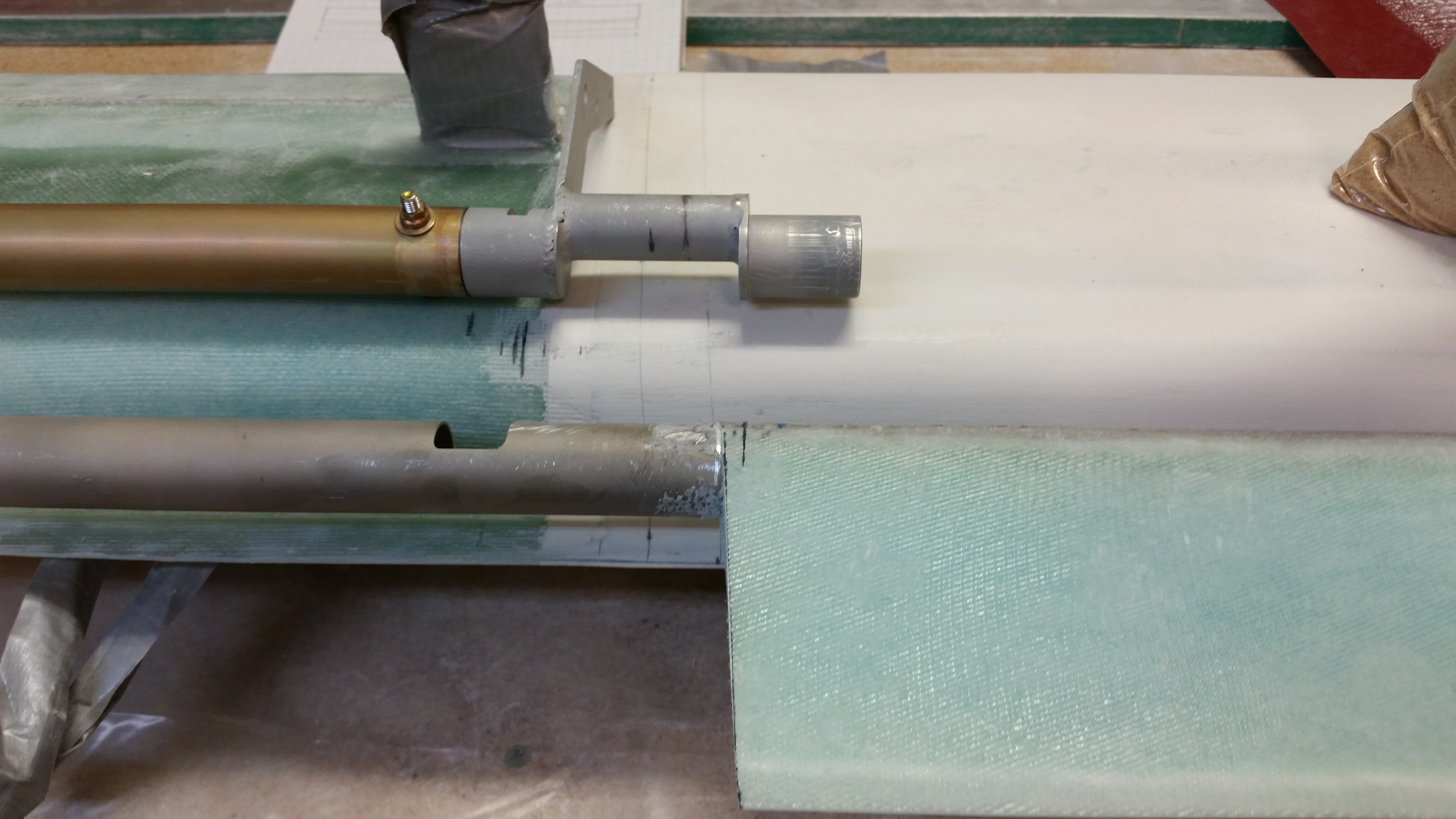
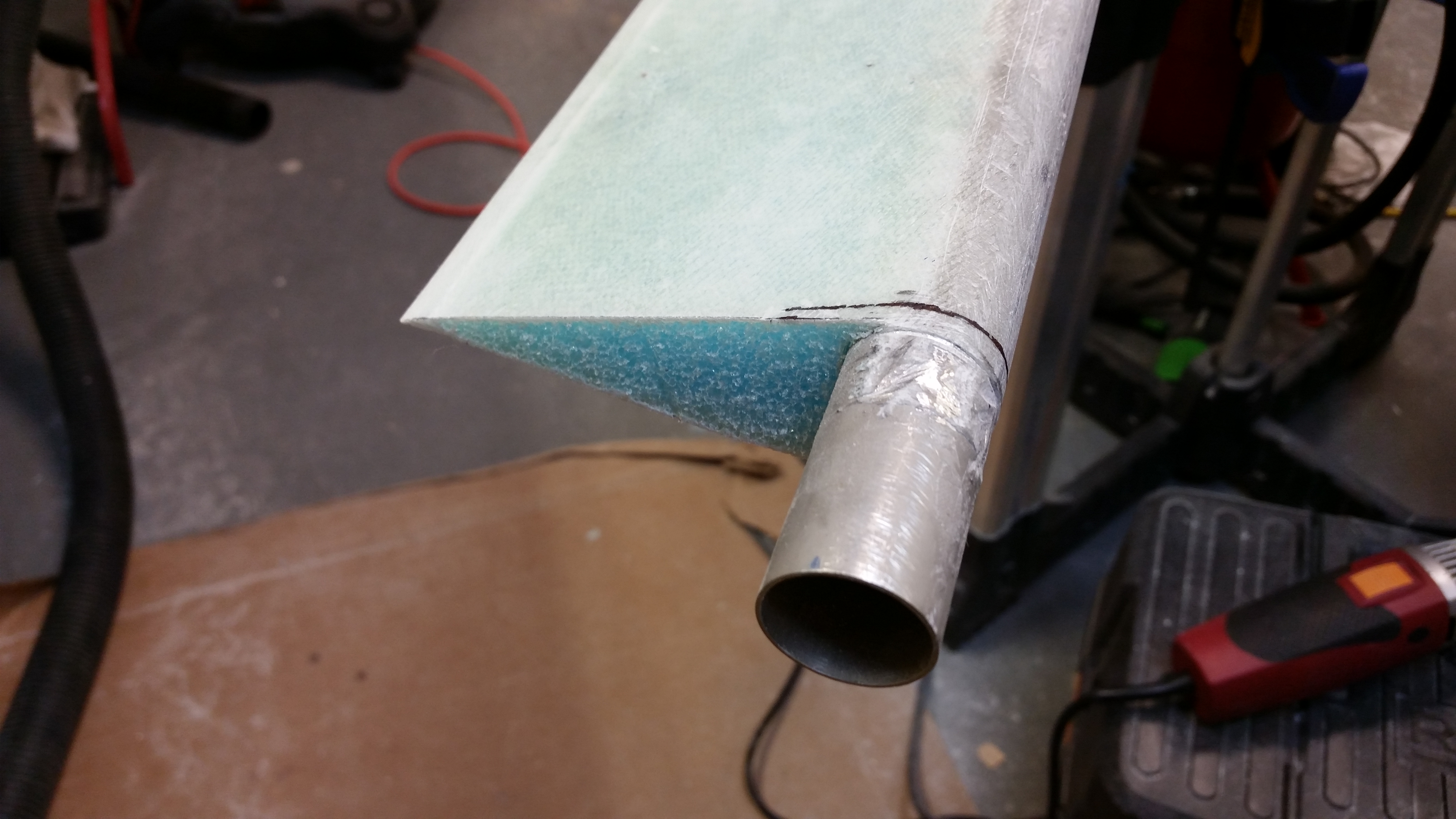
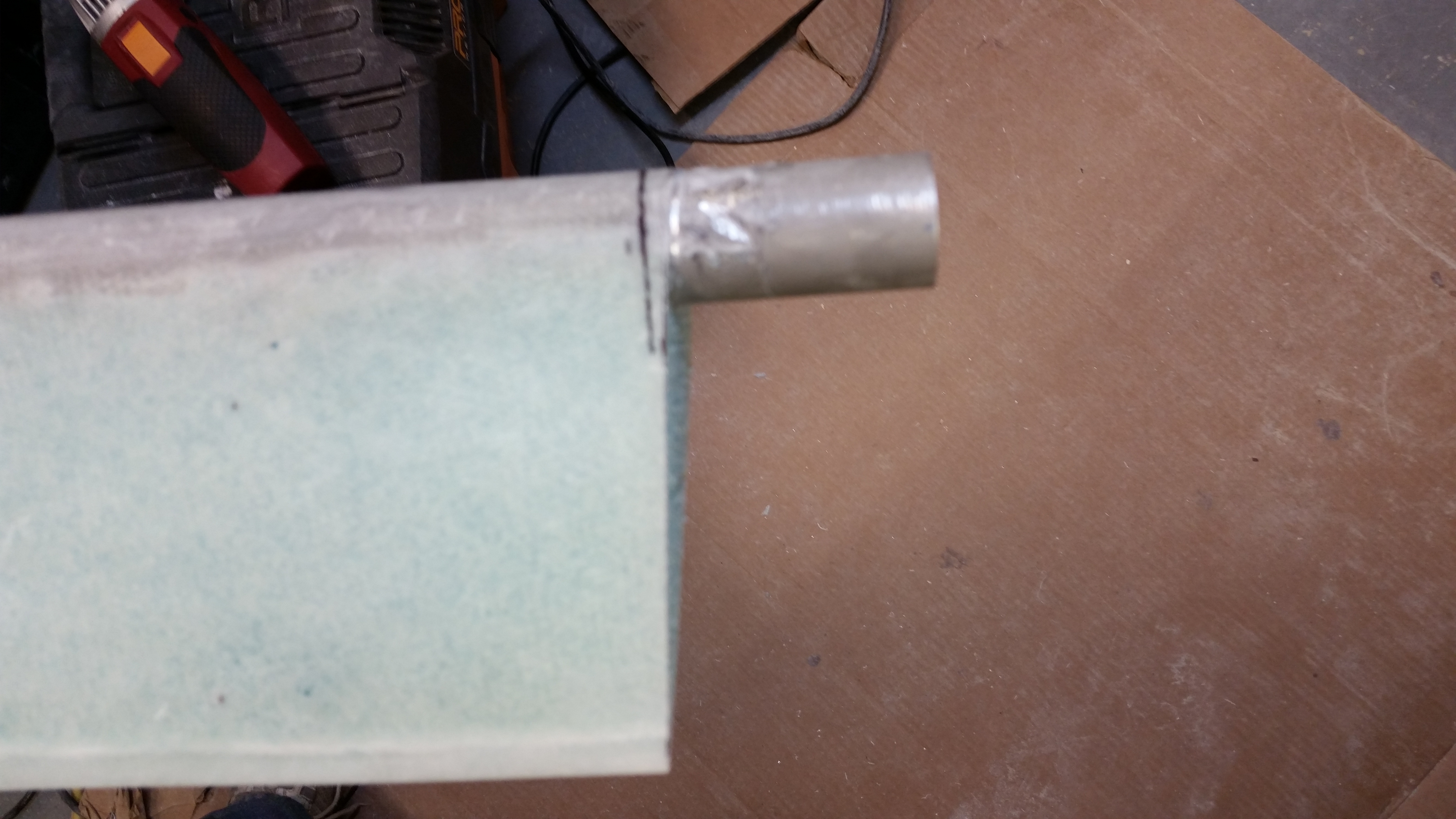
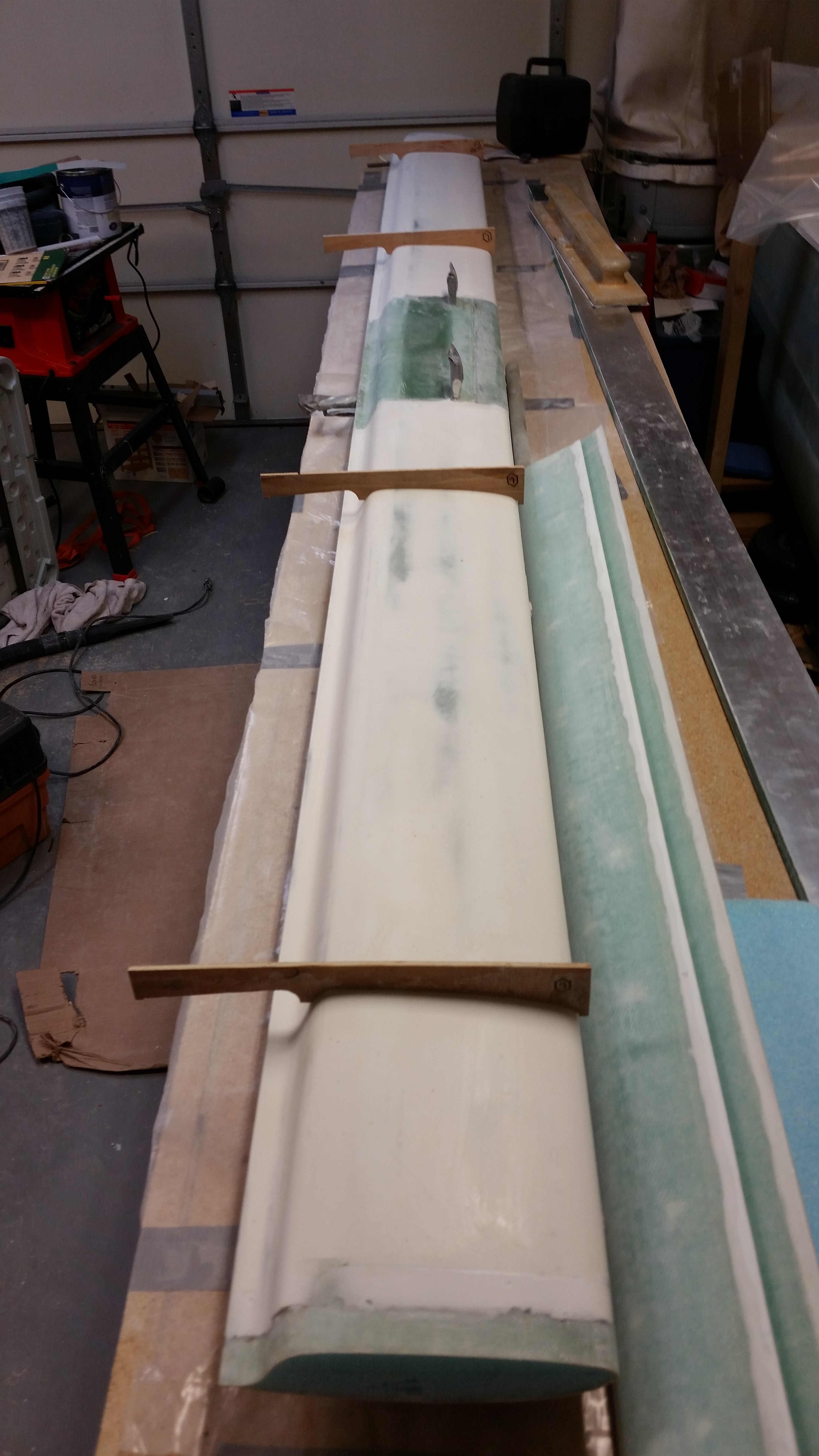
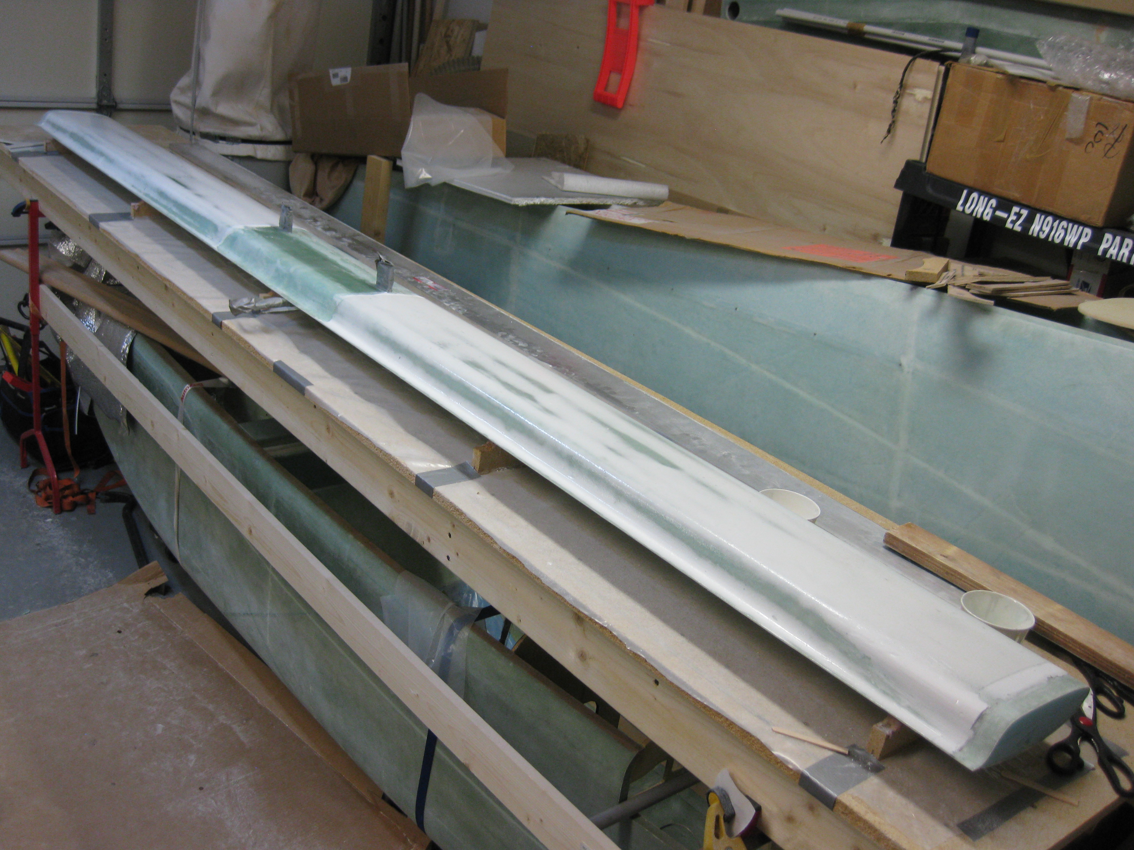
Canard Swoosh Tips

One thing that you may notice that is not per plans is that I started my canard swoosh tip attachment endeavor with the canard mounted upside down.  Per plans this step starts by flipping the canard right side up, but since my canard is “bolted” to the table via Bondo, I decided to start with it upside down and then flip after I had micro’d the tips on. This would allow me to see both sides of the micro bond and ensure all is good.

Canard Swoosh Tips

Here’s the right side of the canard where I repeated the same process as the left.

Canard Swoosh Tip "Blank"

I then confirmed that the dimensions of the blue foam tips would work by marking it up as per plans, only in the upside down configuration.  I also outlined the end profile of the canard to know where to micro the blue foam tip when attaching it to the canard end.

Canard Swoosh Tips

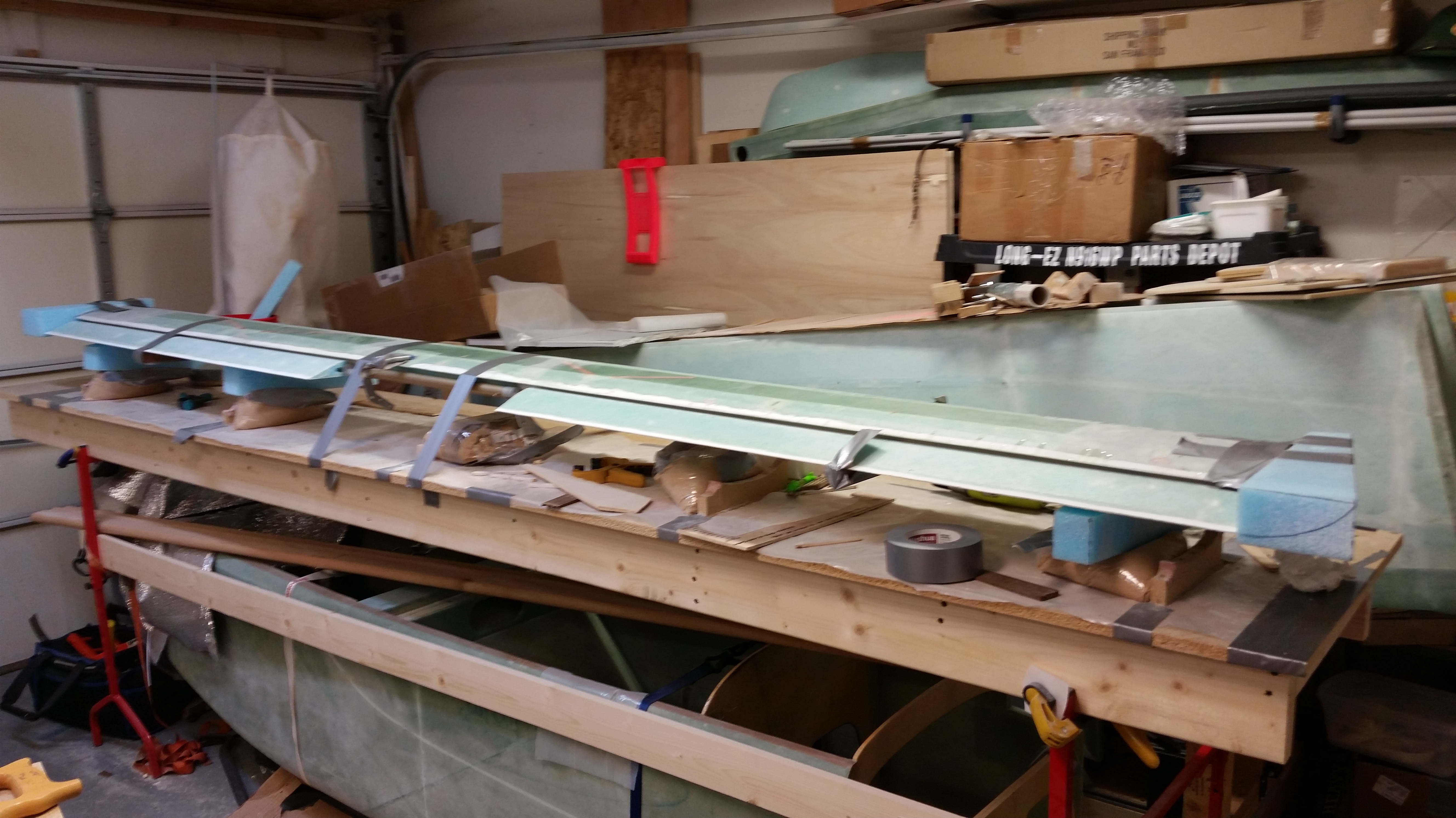
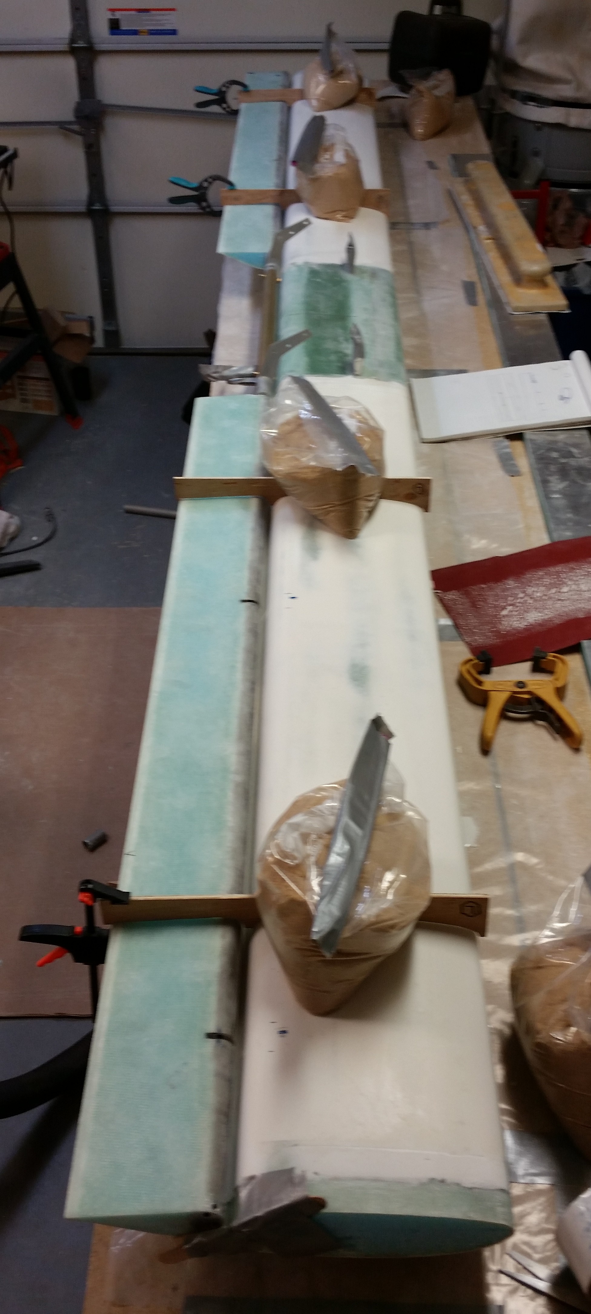
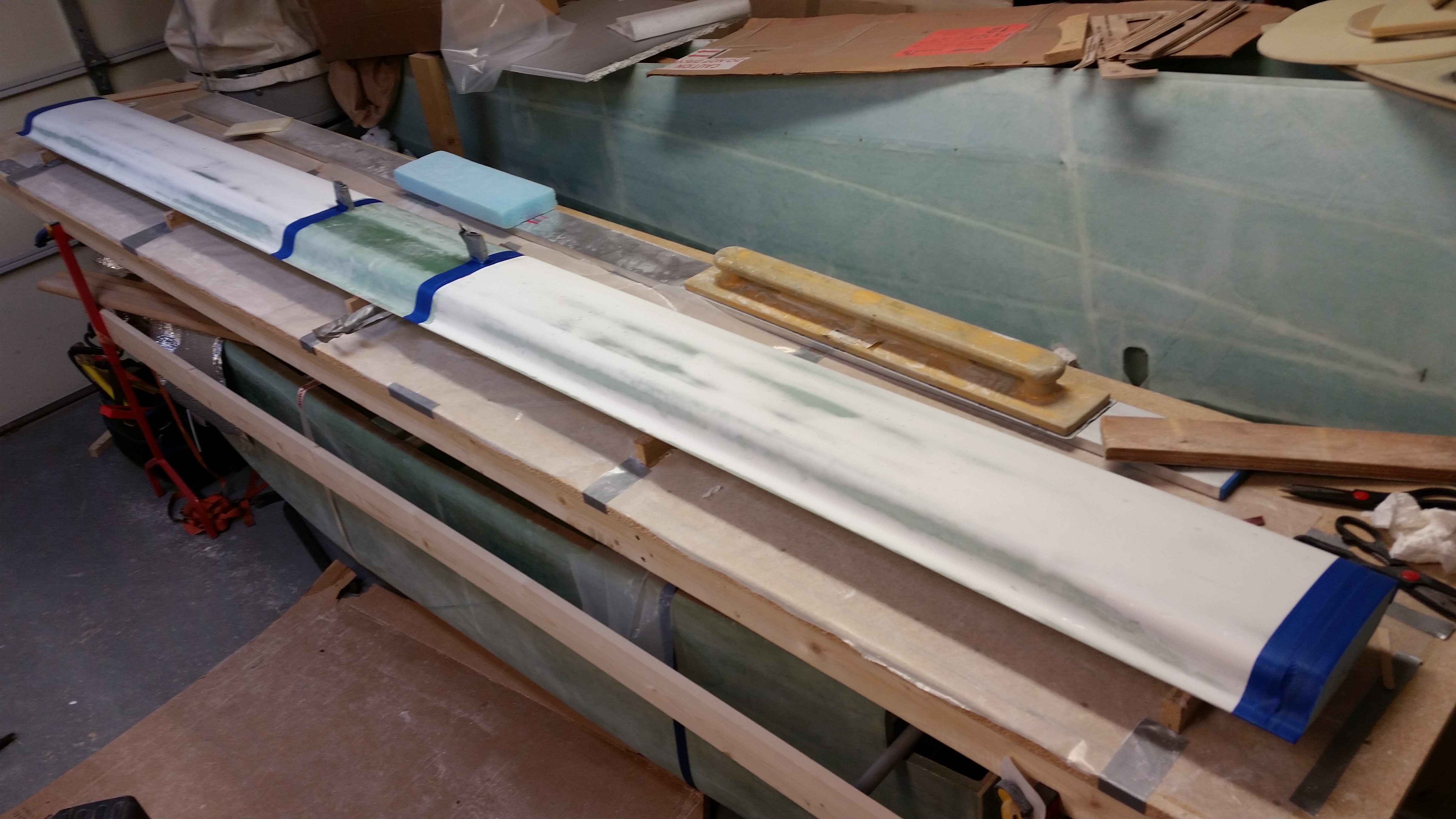
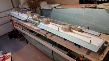
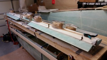
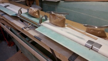
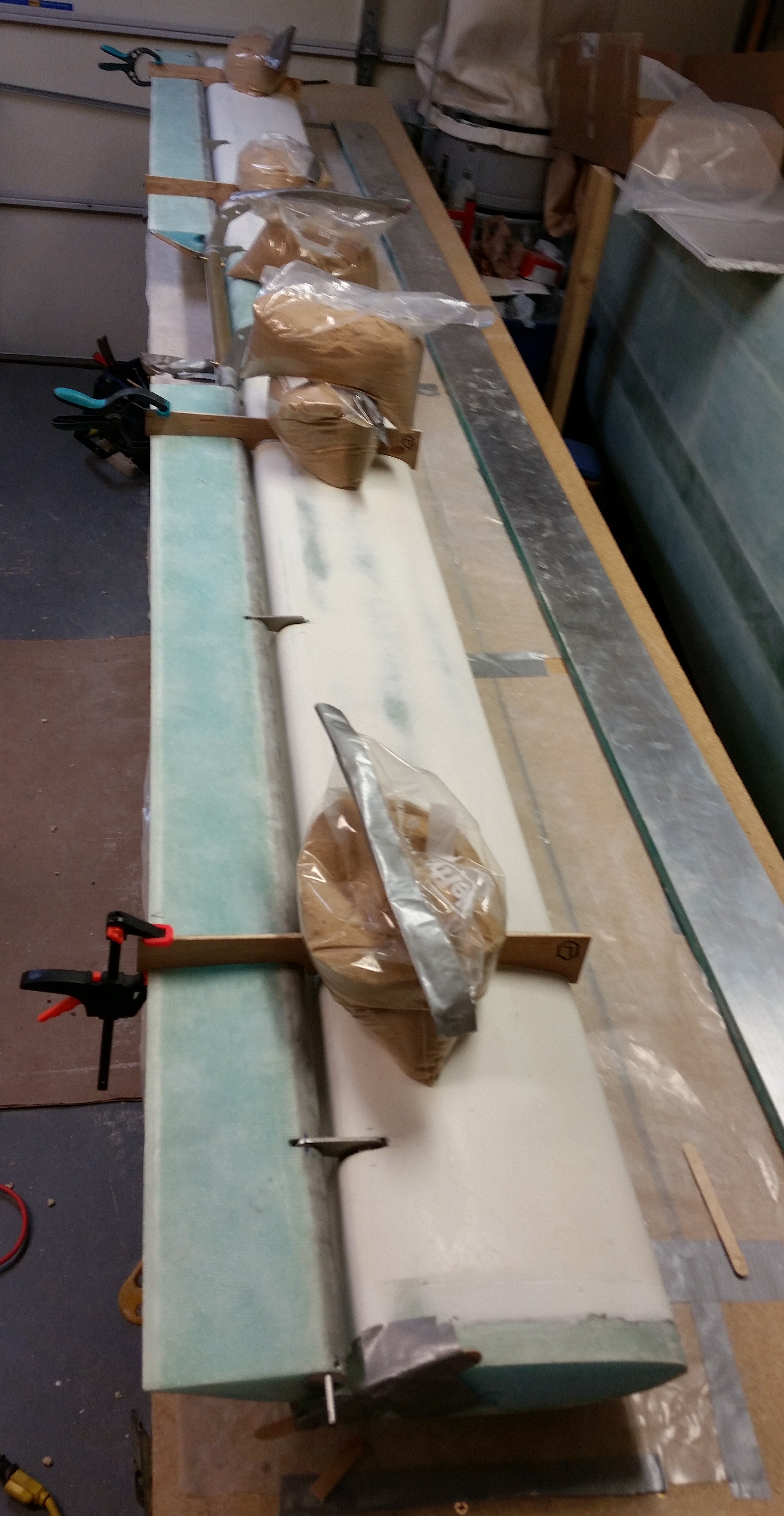
Below are a couple wide angle shots of the canard with the blue foam tips attached.  The first one is the with the canard upside down, and the second pic shows the canard right side up.  I guess you could say the main reason I attached the foam tips to the canard while it was upside down is time.  I wanted to the tips mounted and the micro curing before taking the time to carefully detach the canard from its perch… which I obviously did after the tips were micro’d on.

Micro'ing on swoosh tips

Swoosh tips micro'd/Canard flipped

A long view . . .

Swoosh tips micro'd/Canard flipped

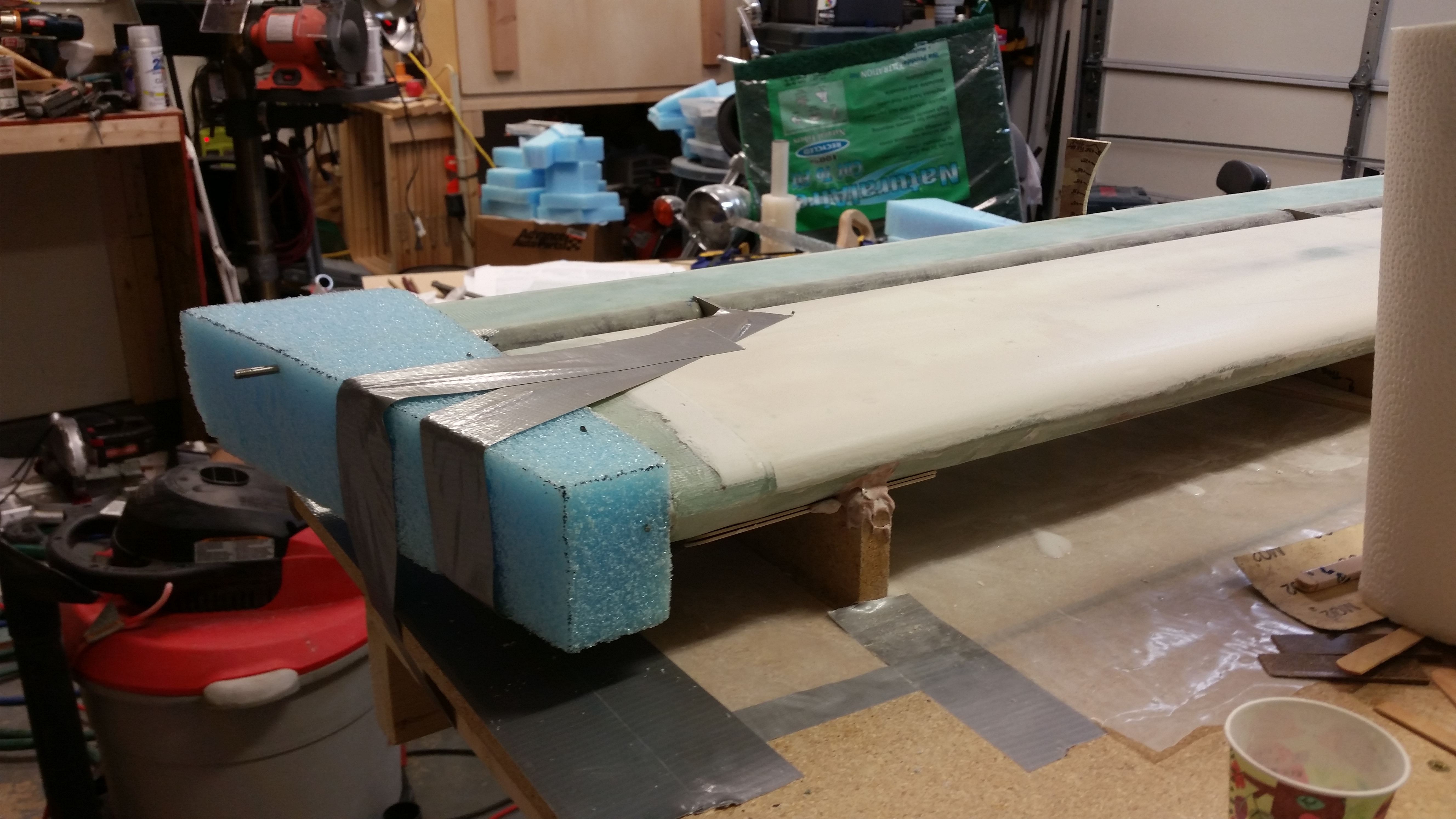
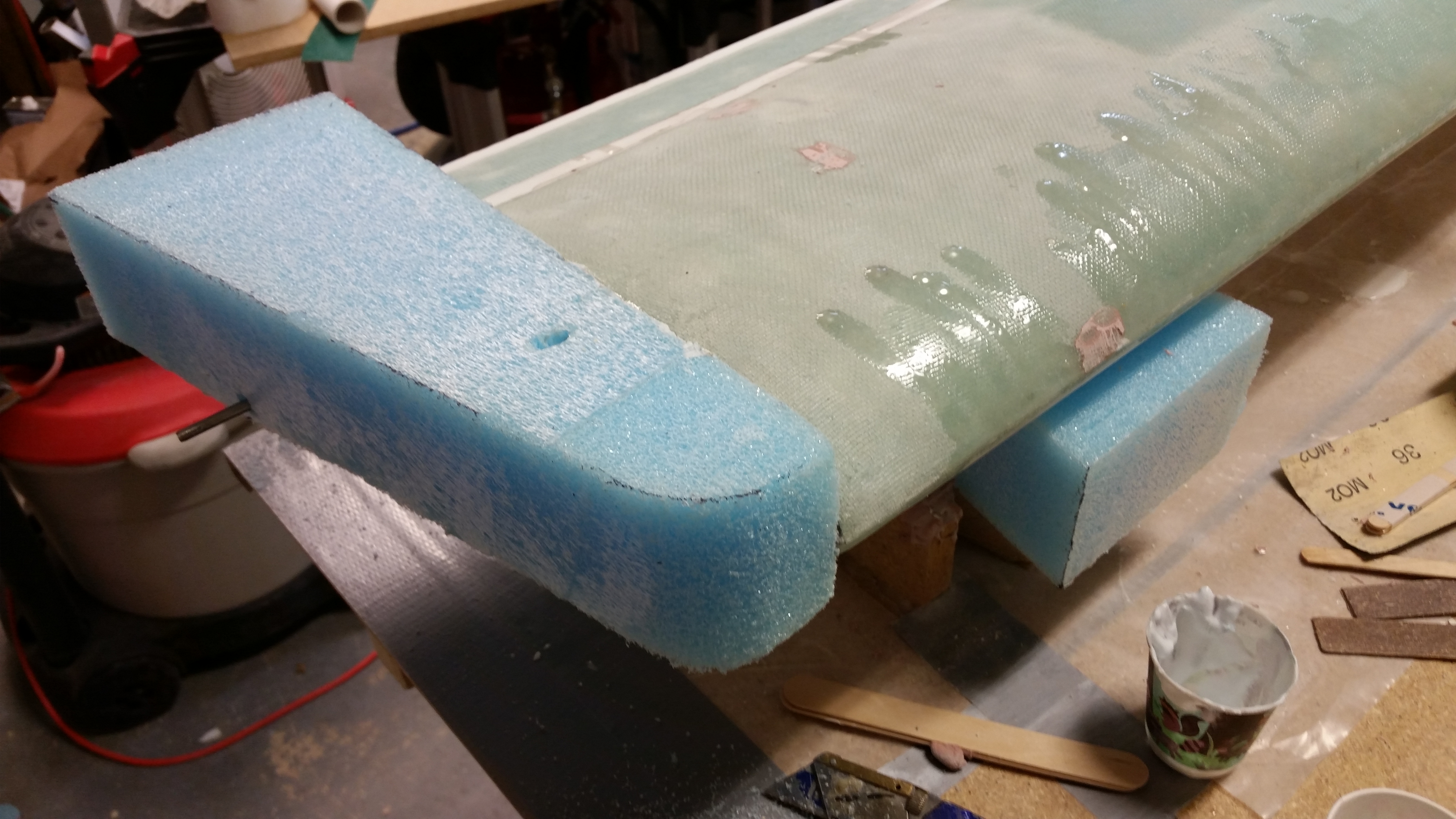
Here’s a more close up shot of the tip micro’d in place while the canard was still upside down.

Left swoosh tip micro'd on

After the micro cured I removed the tape securing the blocks.

Swoosh tip micro'd on

Swoosh tip micro'd on

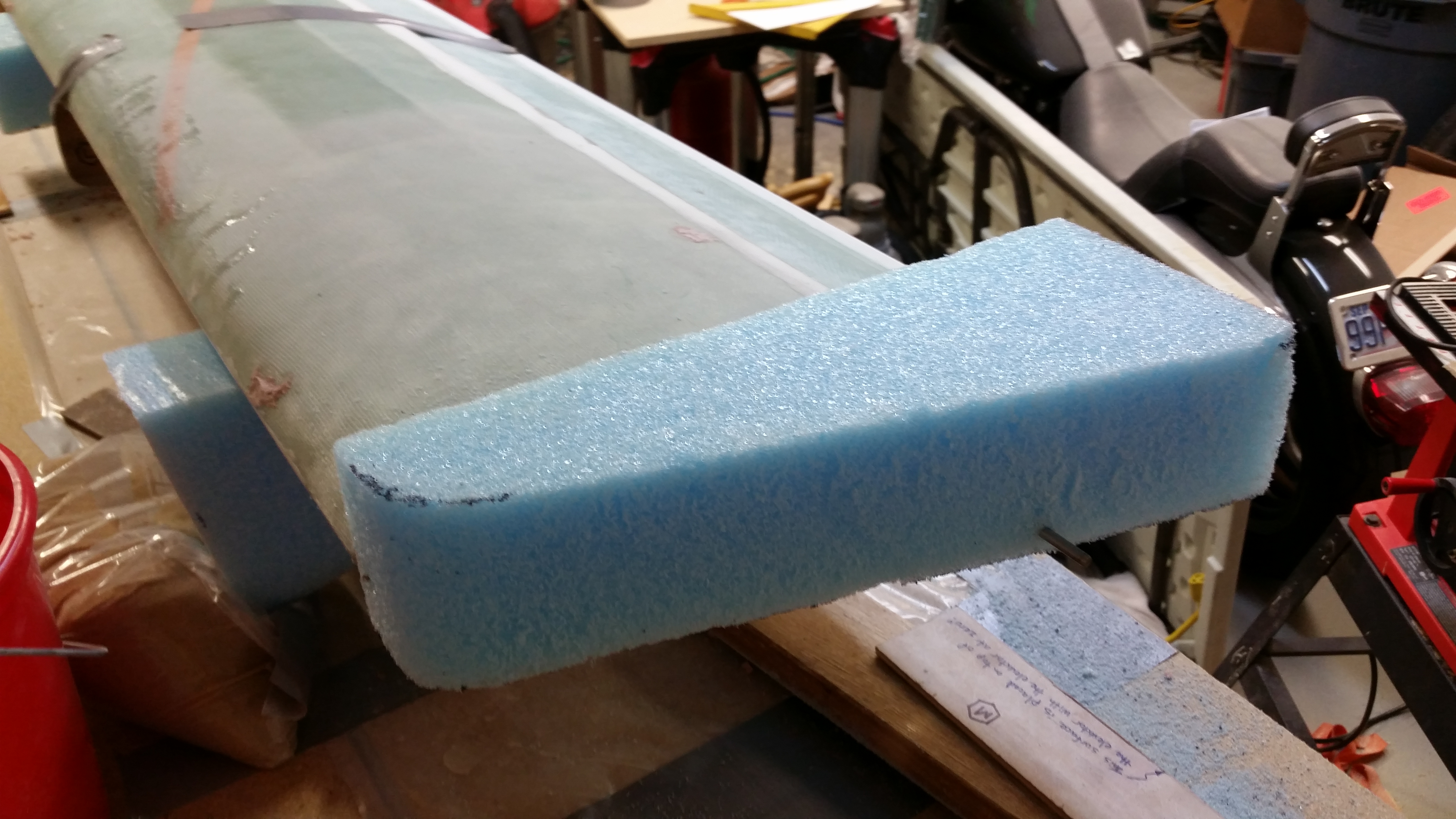
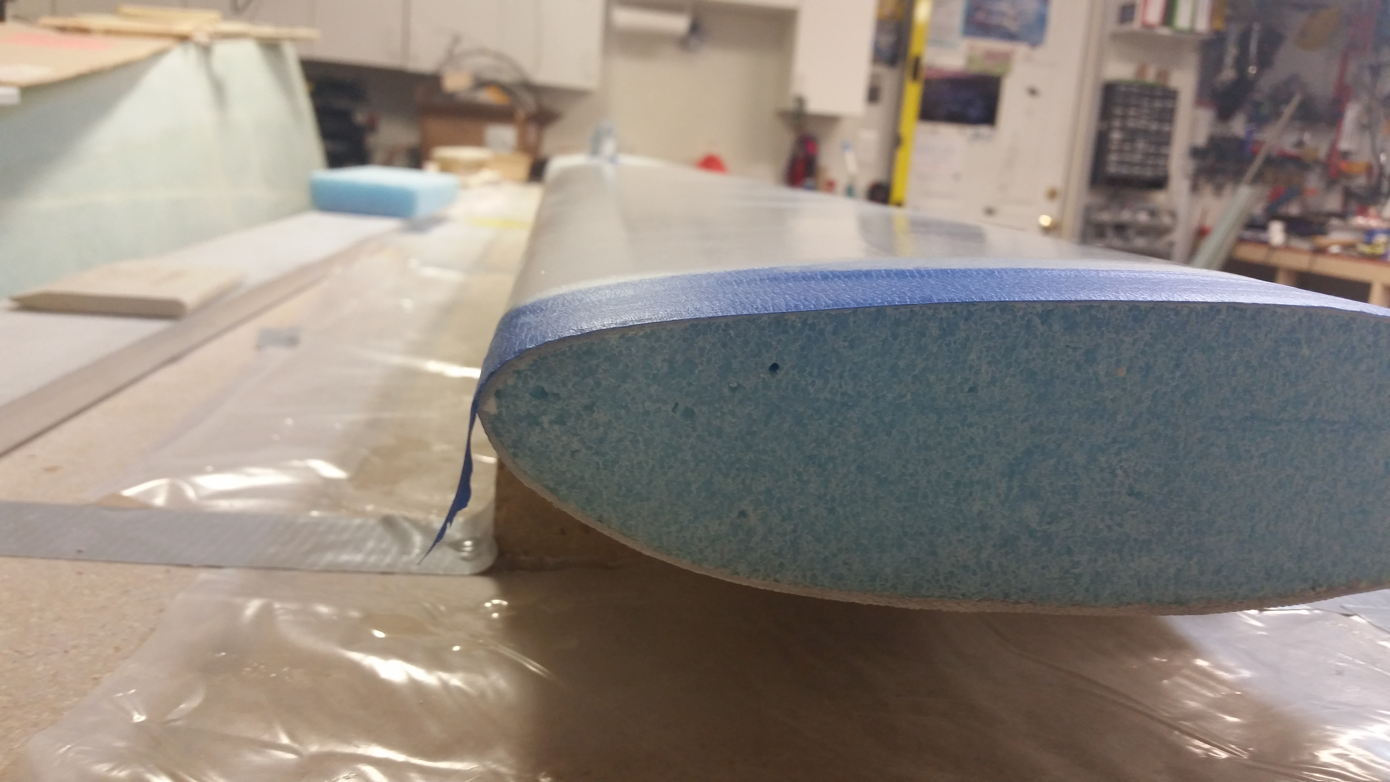
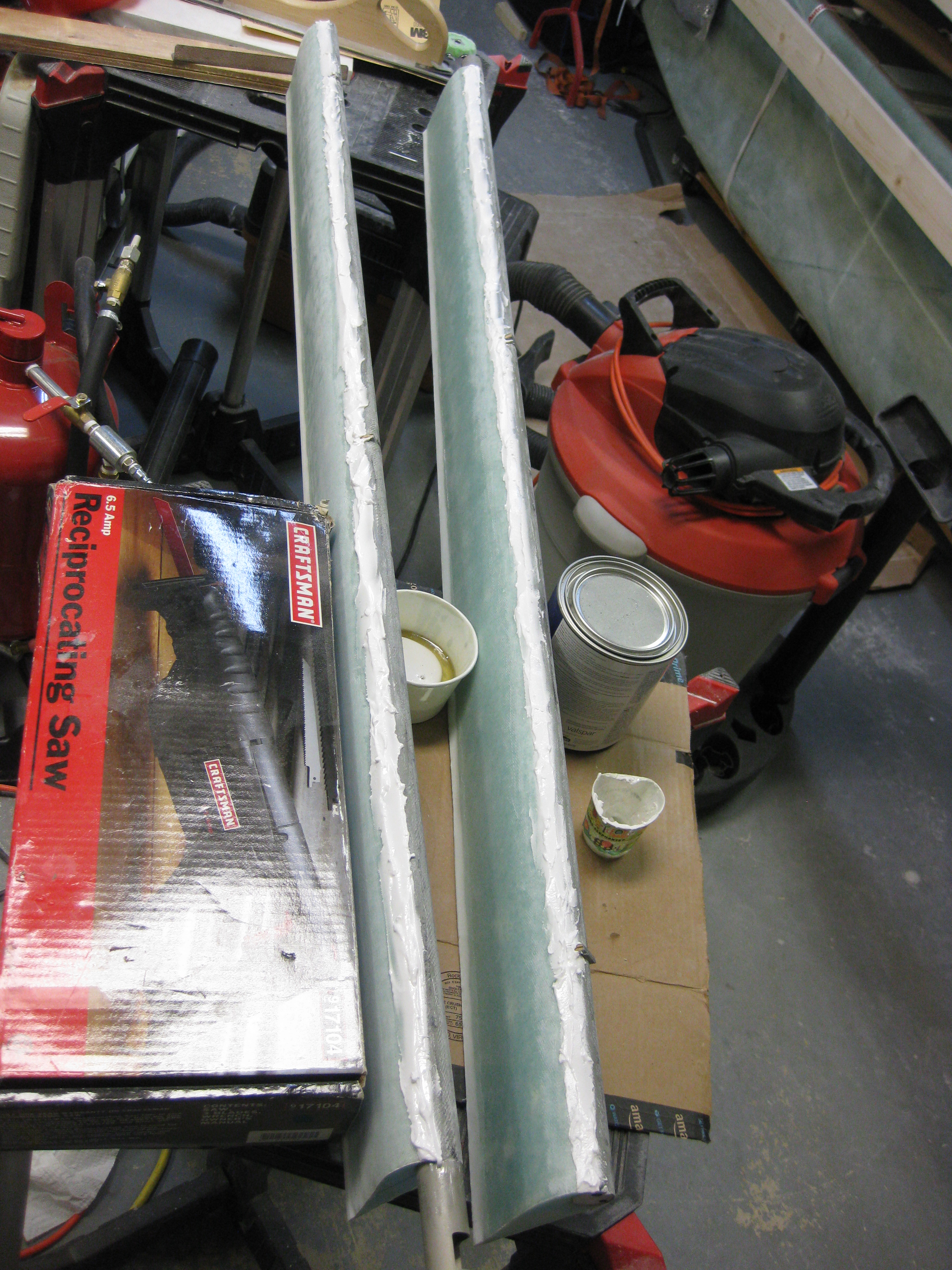
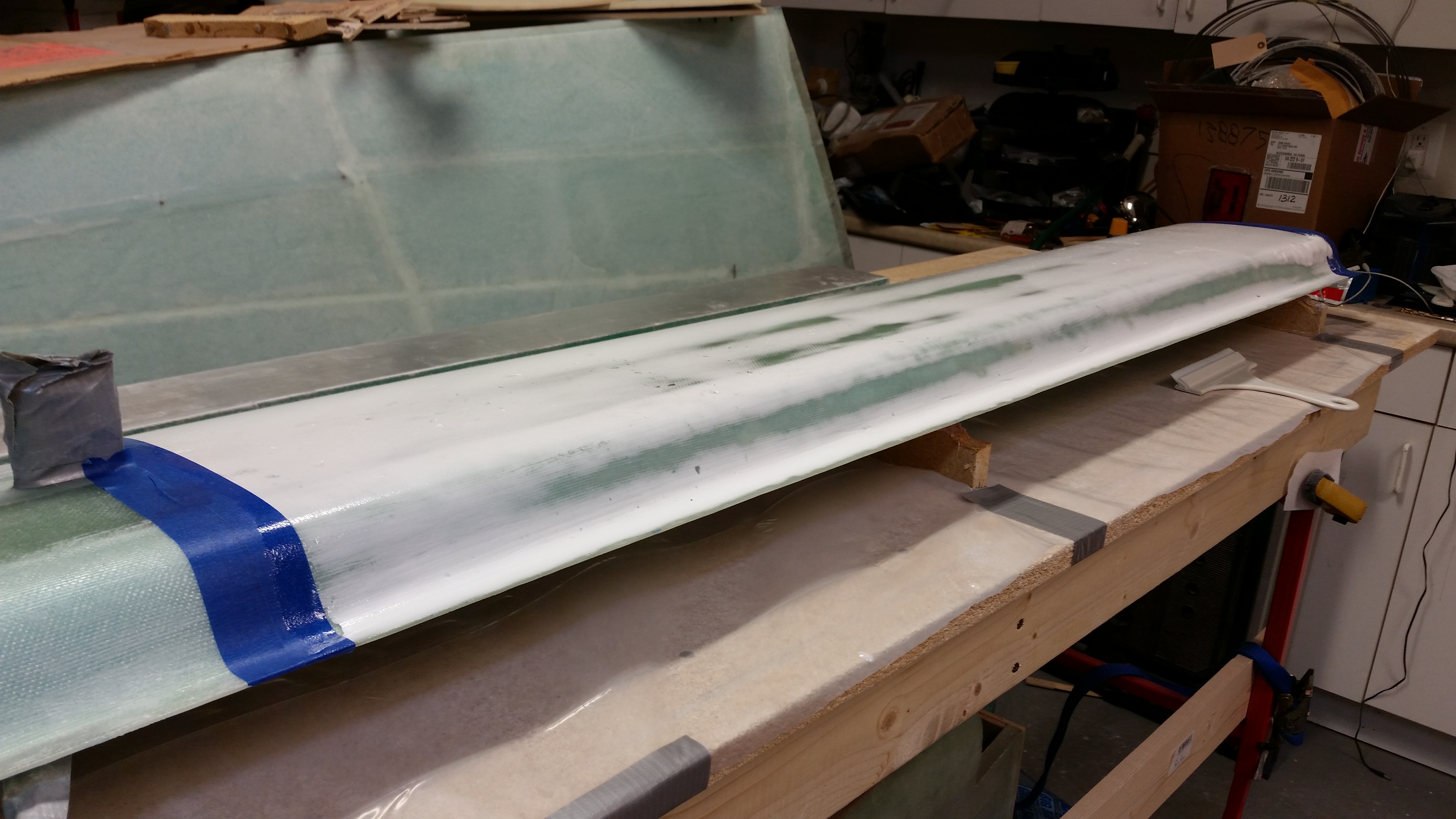
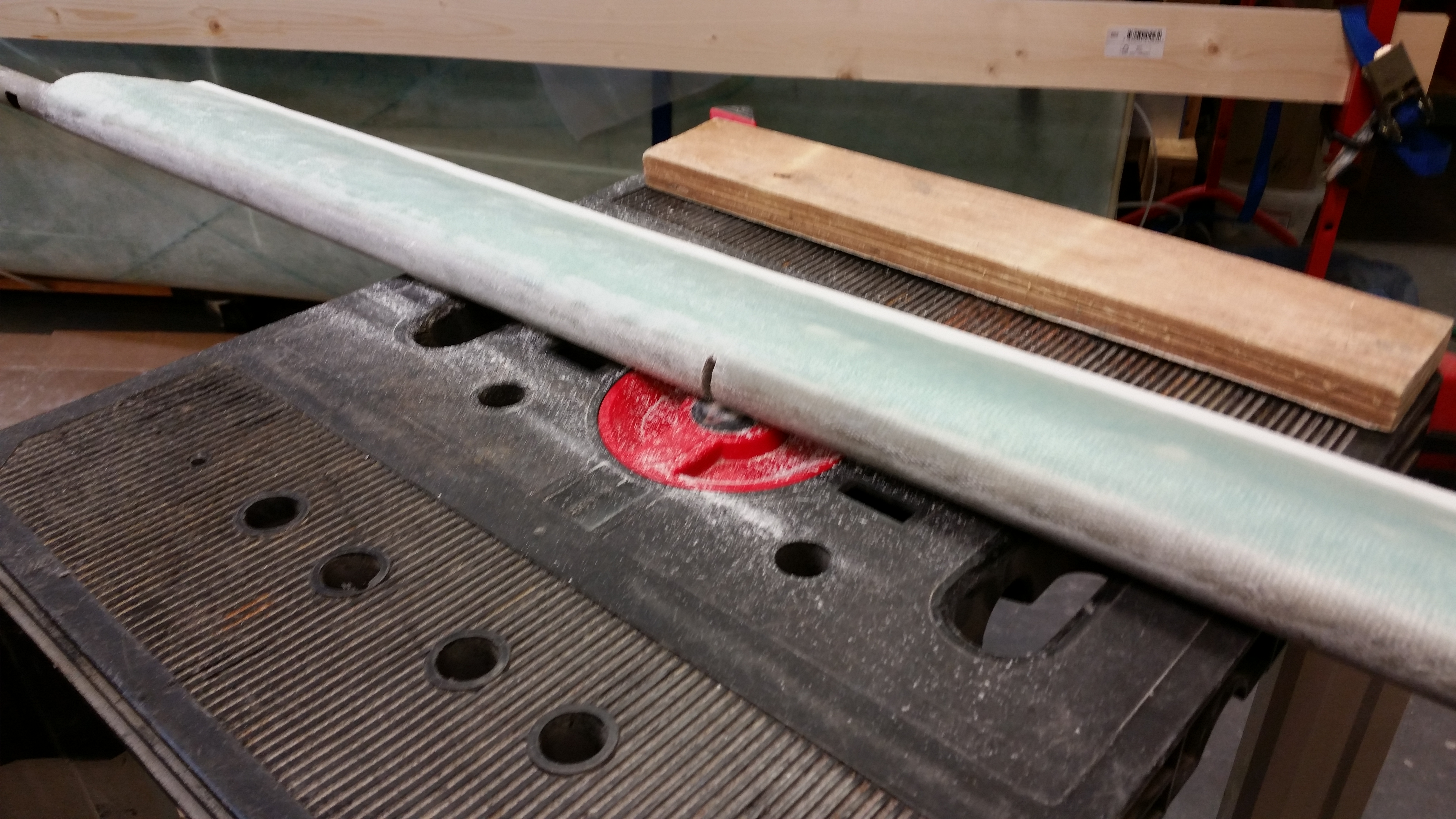
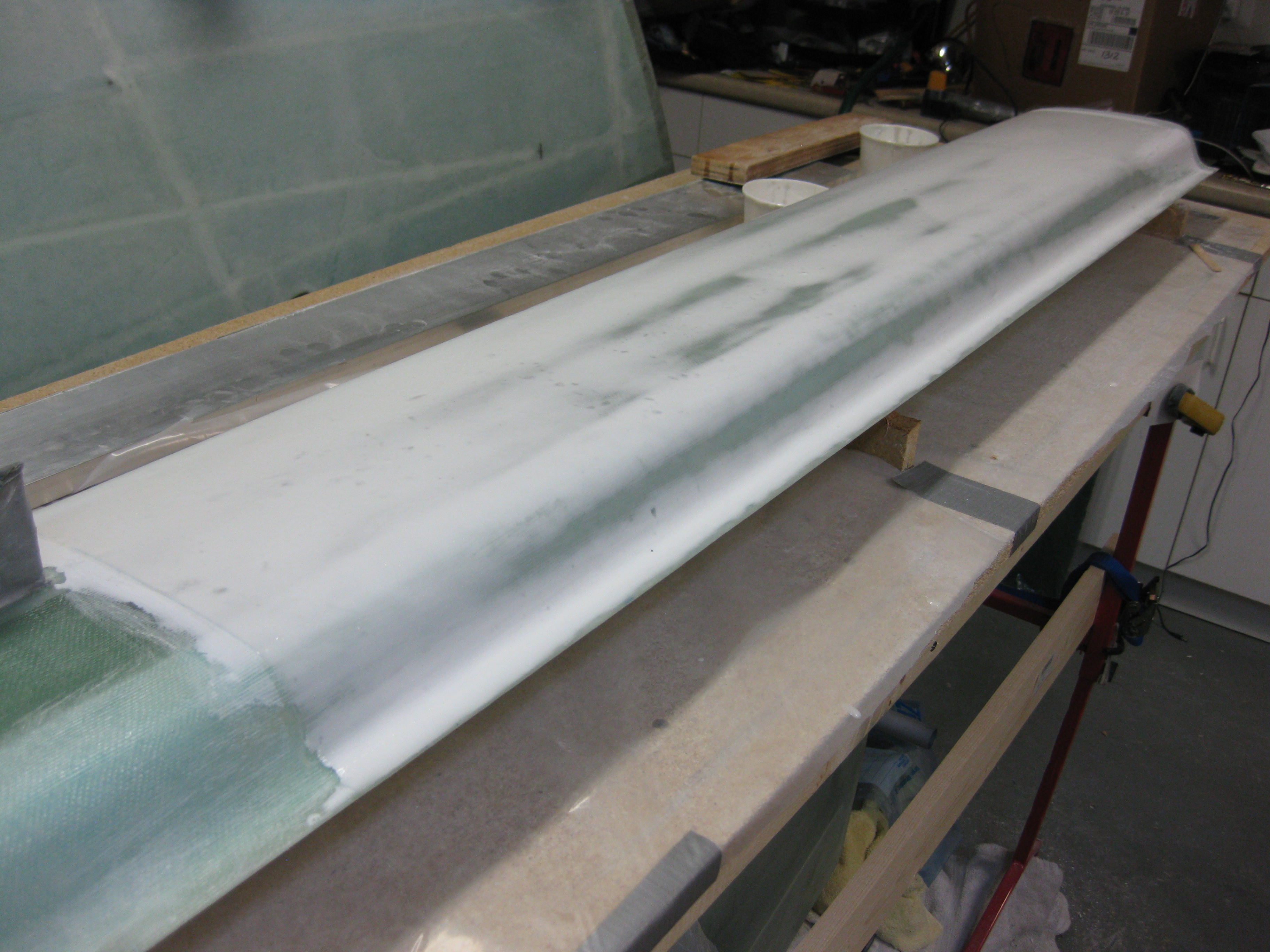
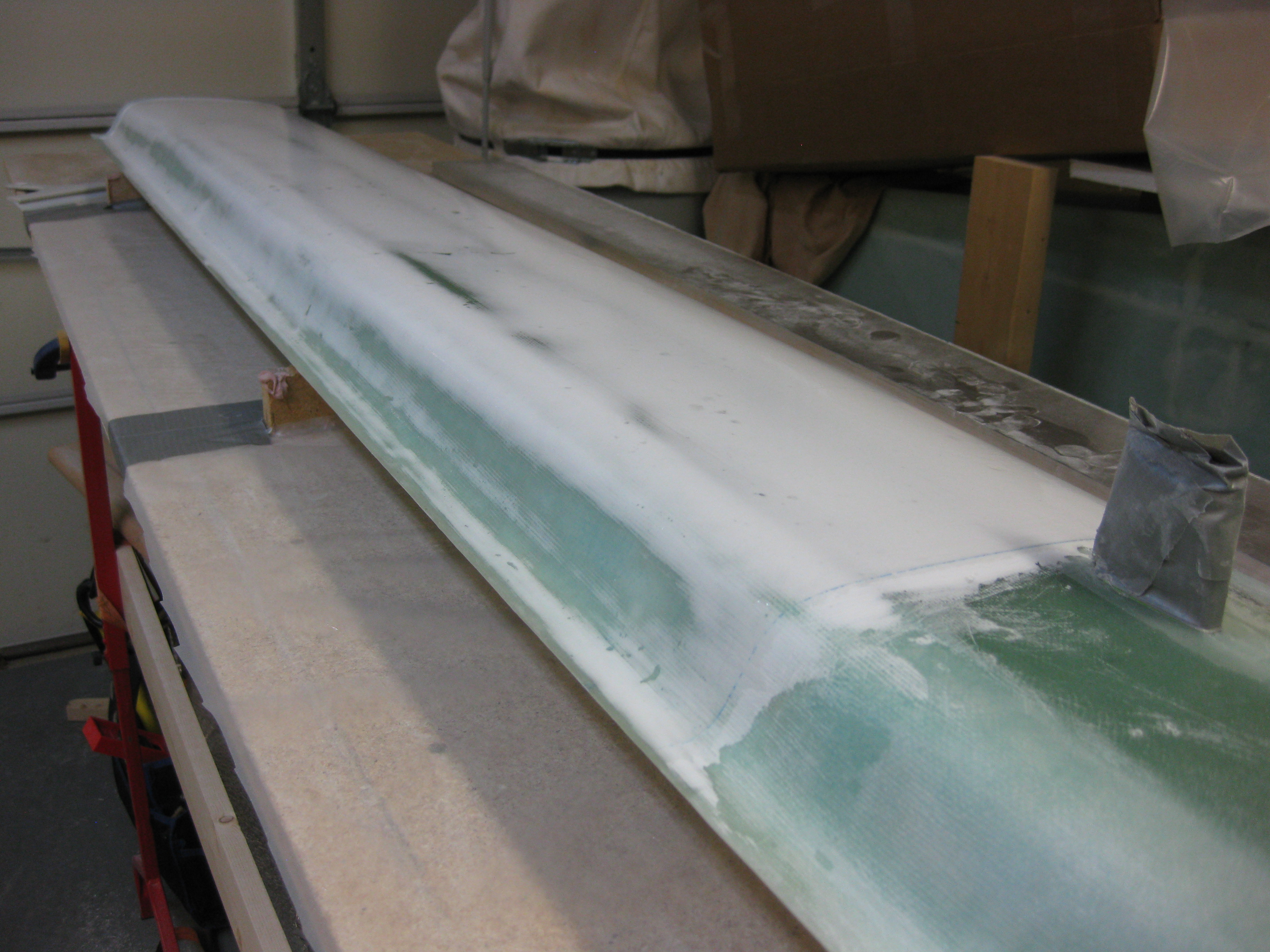
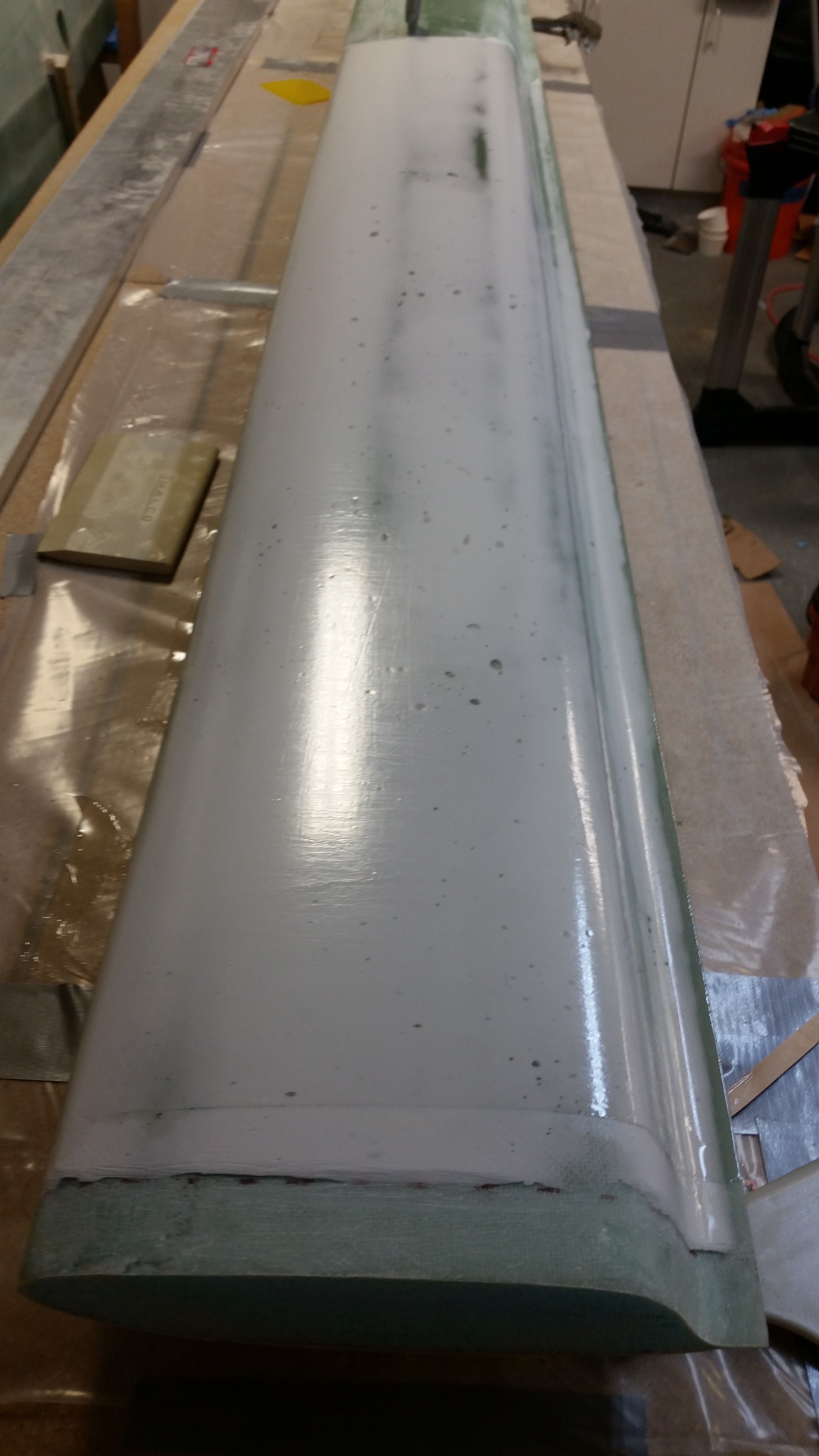
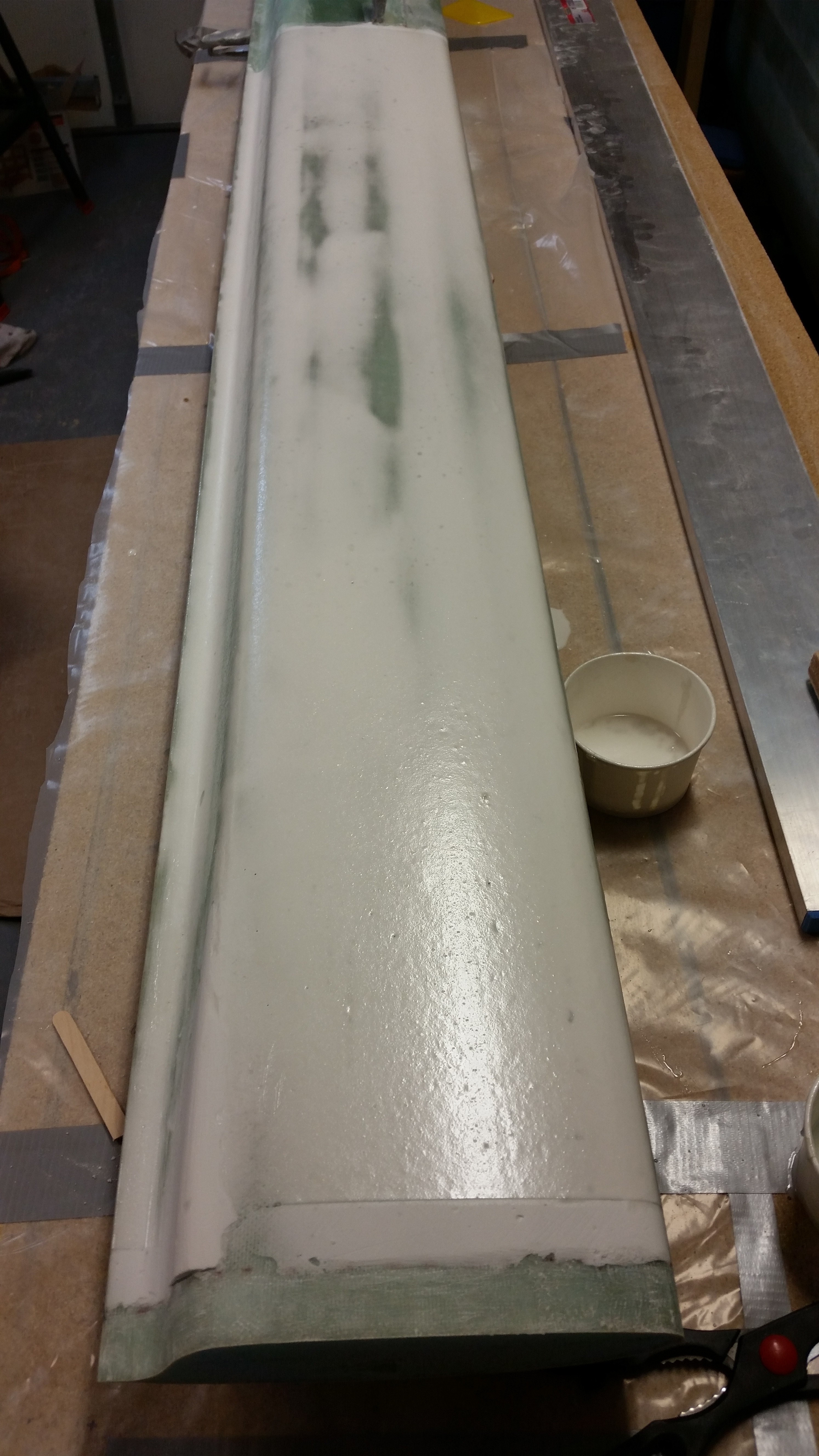
I then rounded the front of each blue foam tip in line with my initial plan for the shape of the  swoosh tip.

Swoosh tip curve

Swoosh tip curve

Tomorrow I plan to get the canard swoosh tips shaped and glassed, at least the top sides.


Chapter 11 – Elevators Installed, etc.

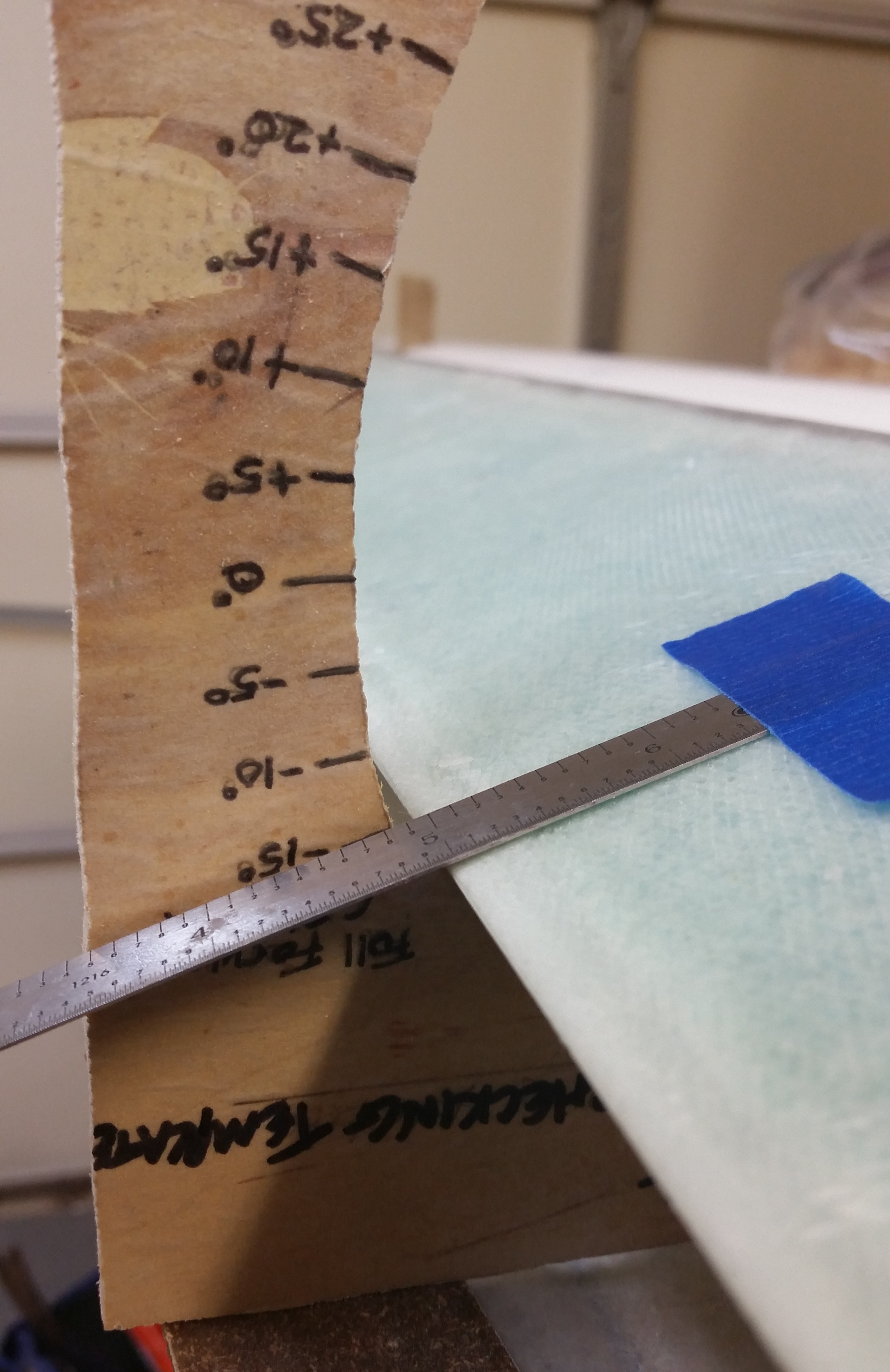
First thing this morning I checked the elevator up travel to ensure that my floxing in the middle hinge on each side didn’t gum up my good numbers thus far.  The right elevator was now sitting right at 15° . . .

Right elevator up travel

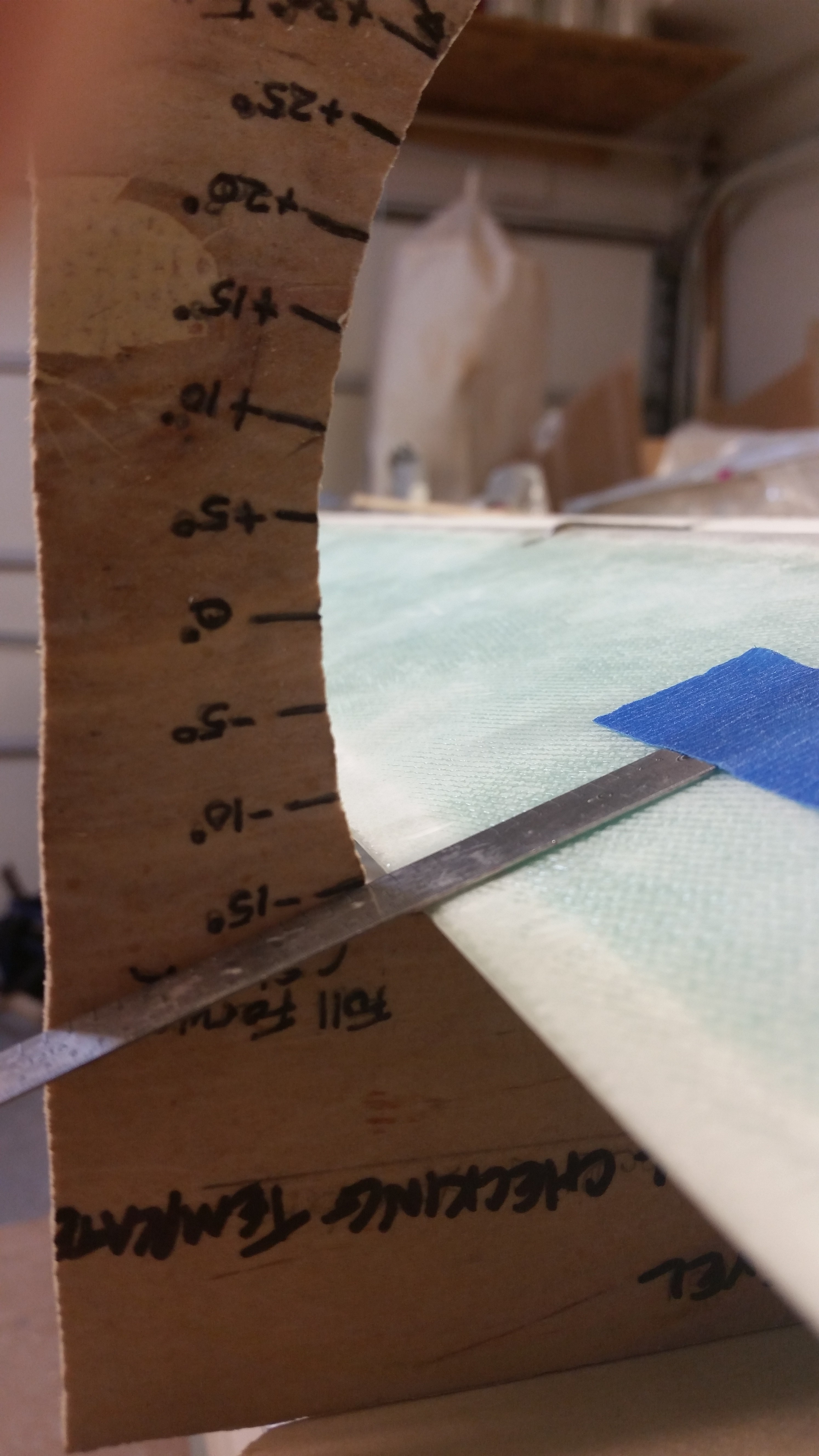
. . . while the left elevator was just a hair over 15°.  So the pattern continues that the left elevator is seeing about a .5 to maybe 1° higher swing than the right.  However, this could be the contour of the canard top where I have the “G” template mounted, or something else entirely.  The bottom line is that the elevators are matched, travel in unison, and the most limiting point in up travel allows a full 15° up, so I’m happy.

Left elevator up travel

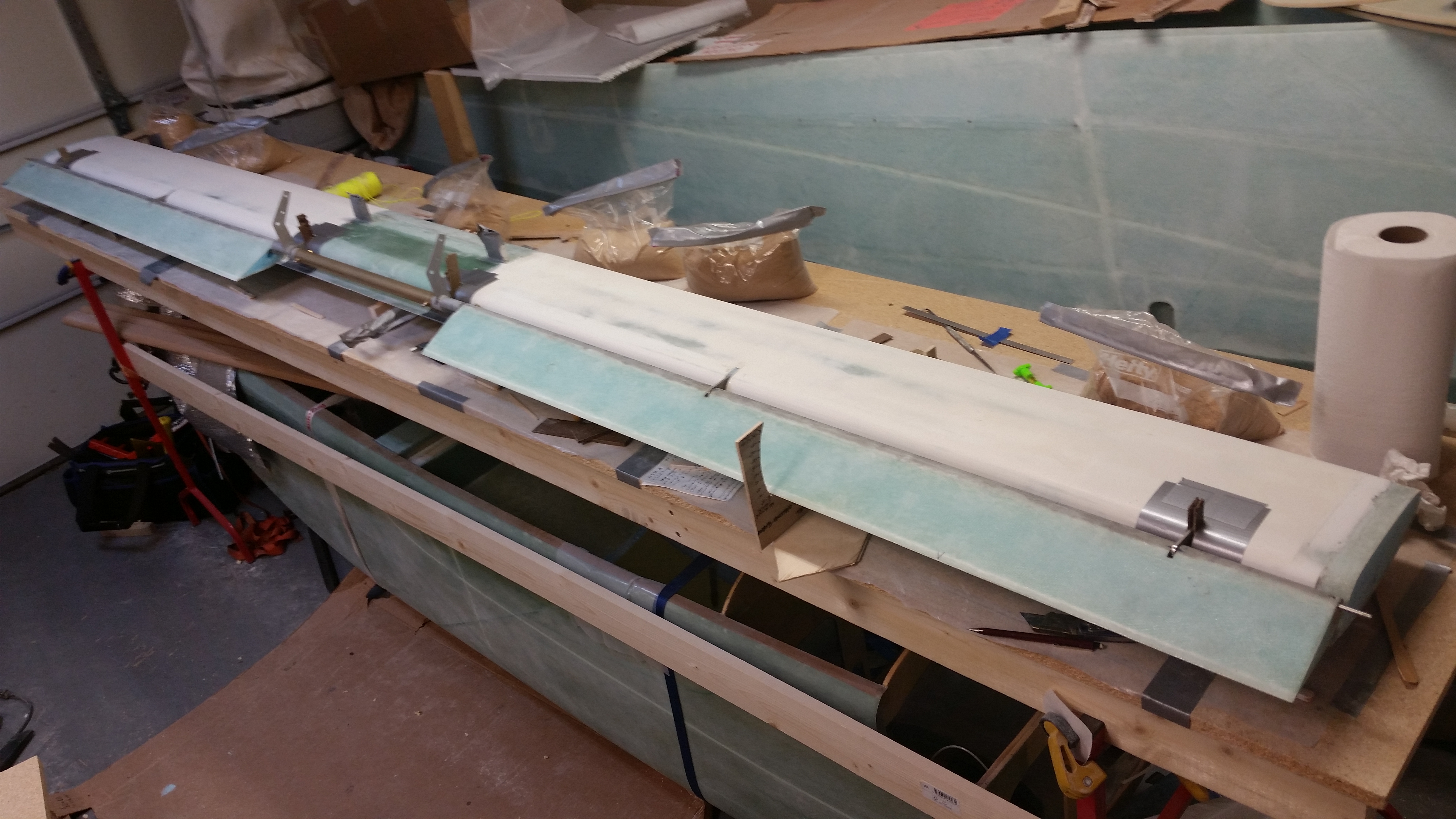
Below is a wide-angle shot after I taped up the other 4 hinge slots in prep for flox.

Floxing 3 more hinges!

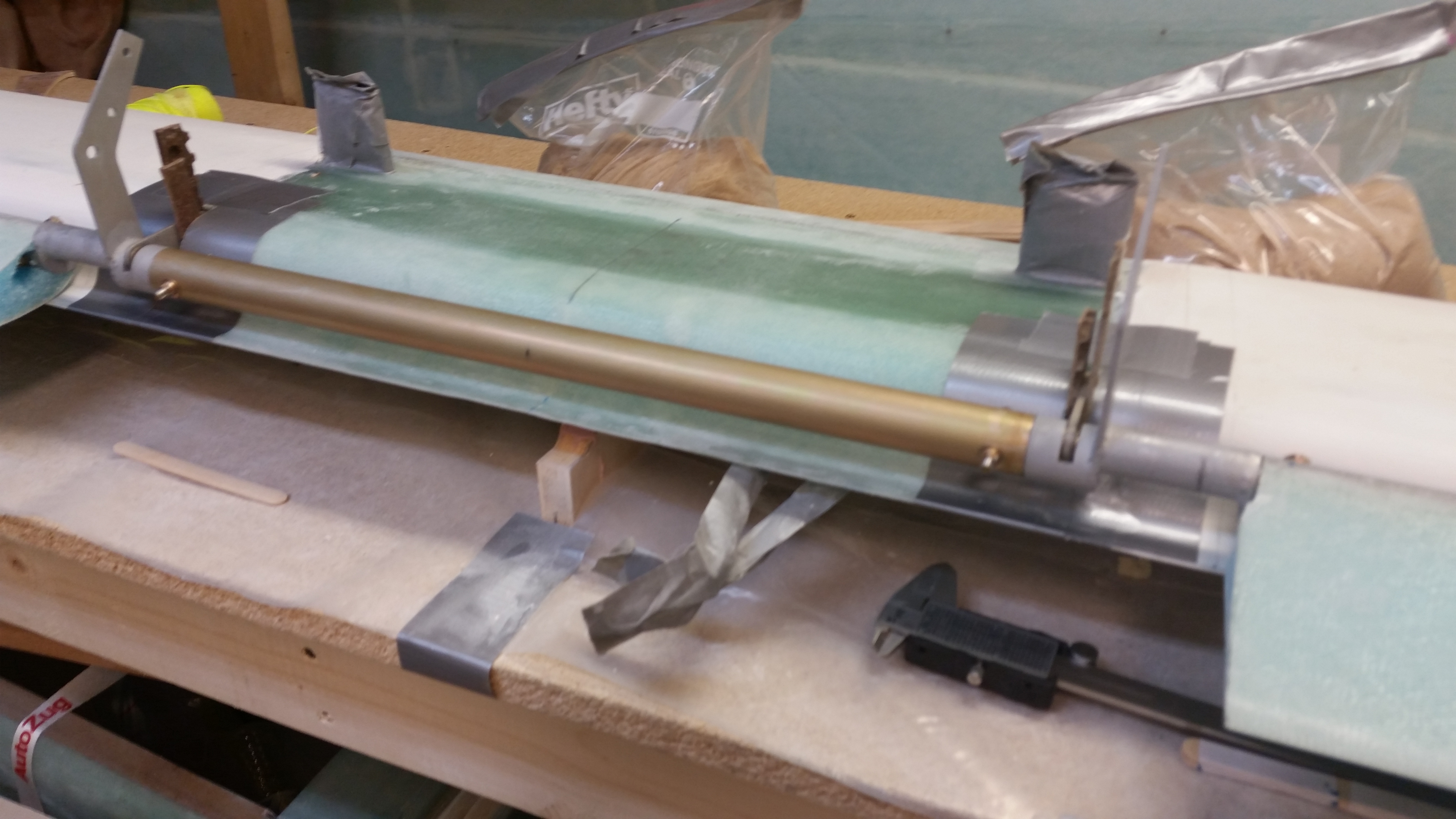
And here’s the busier mid-canard area with the two hinges that connect the respective torque offsets to the elevators and spool tube — taped and ready for flox.

Middle hinges prepped

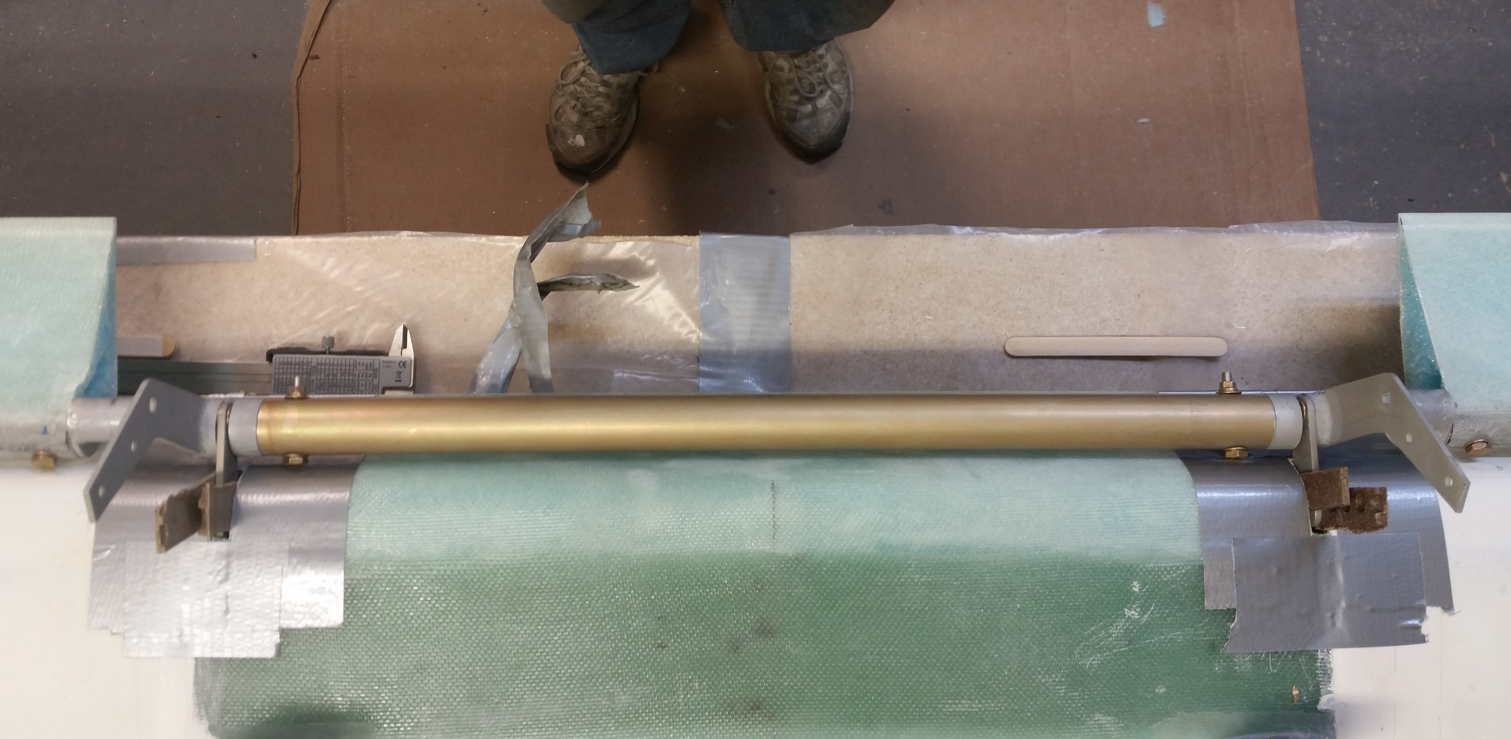
I realized that I hadn’t yet taken a good (or passible in this case) shot of the bolts attaching the elevators to the torque offsets from the front side of the elevator.  Here you can make out the bolt heads at the root of each elevator at each side of the pic.

Spool tube assembly

Next, I floxed in 3 more hinge tabs.  The left Inboard hinge needed just a slight bit of coercive pressure to get it to line up correctly (we’re talking around 20 thou in movement), so I decided to get it set, leave it alone, and work on the other 3 hinges to limit my variables on this round of floxing.

Left outboard hingeRight inboard hingeRight outboard hinge

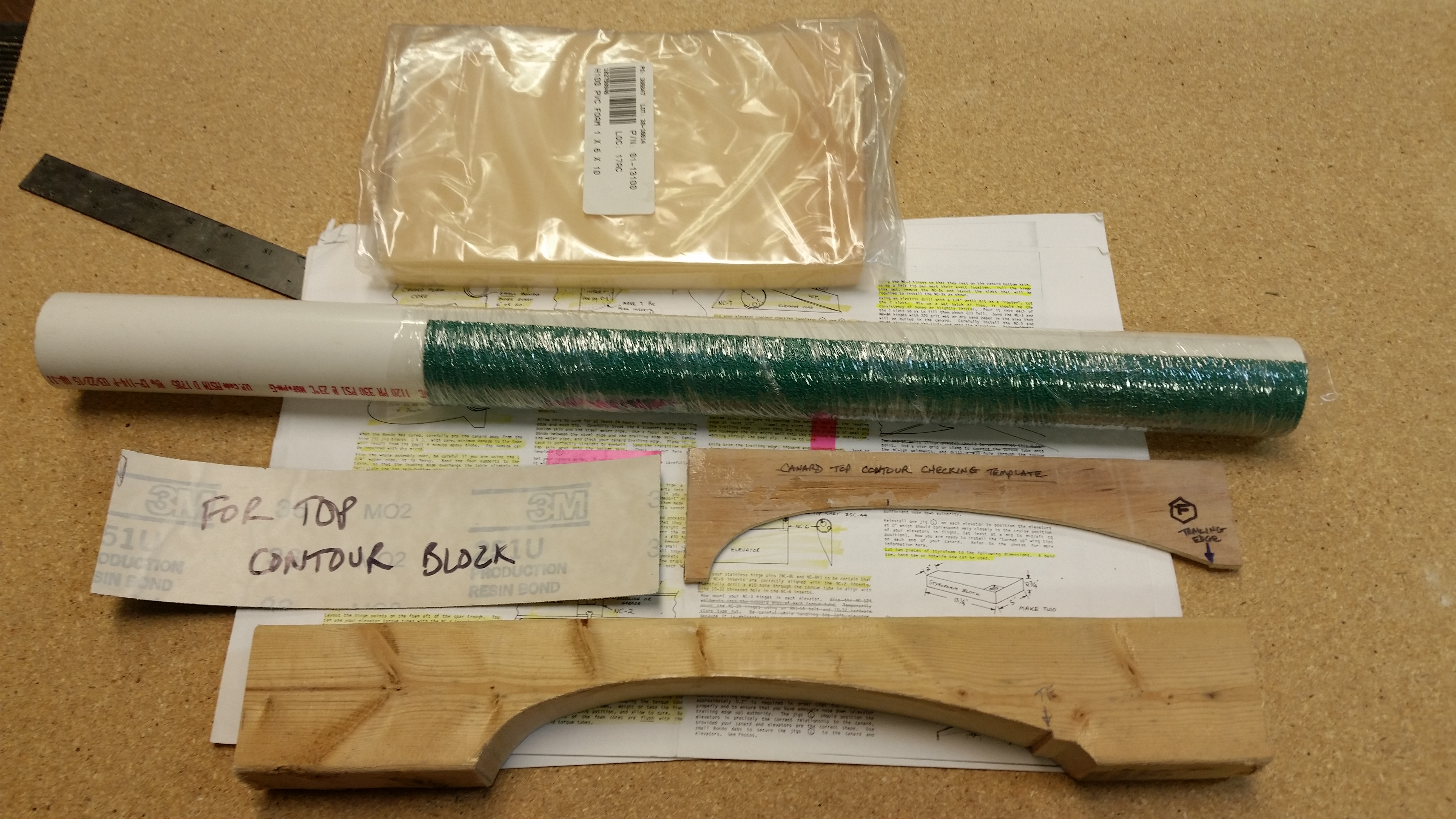
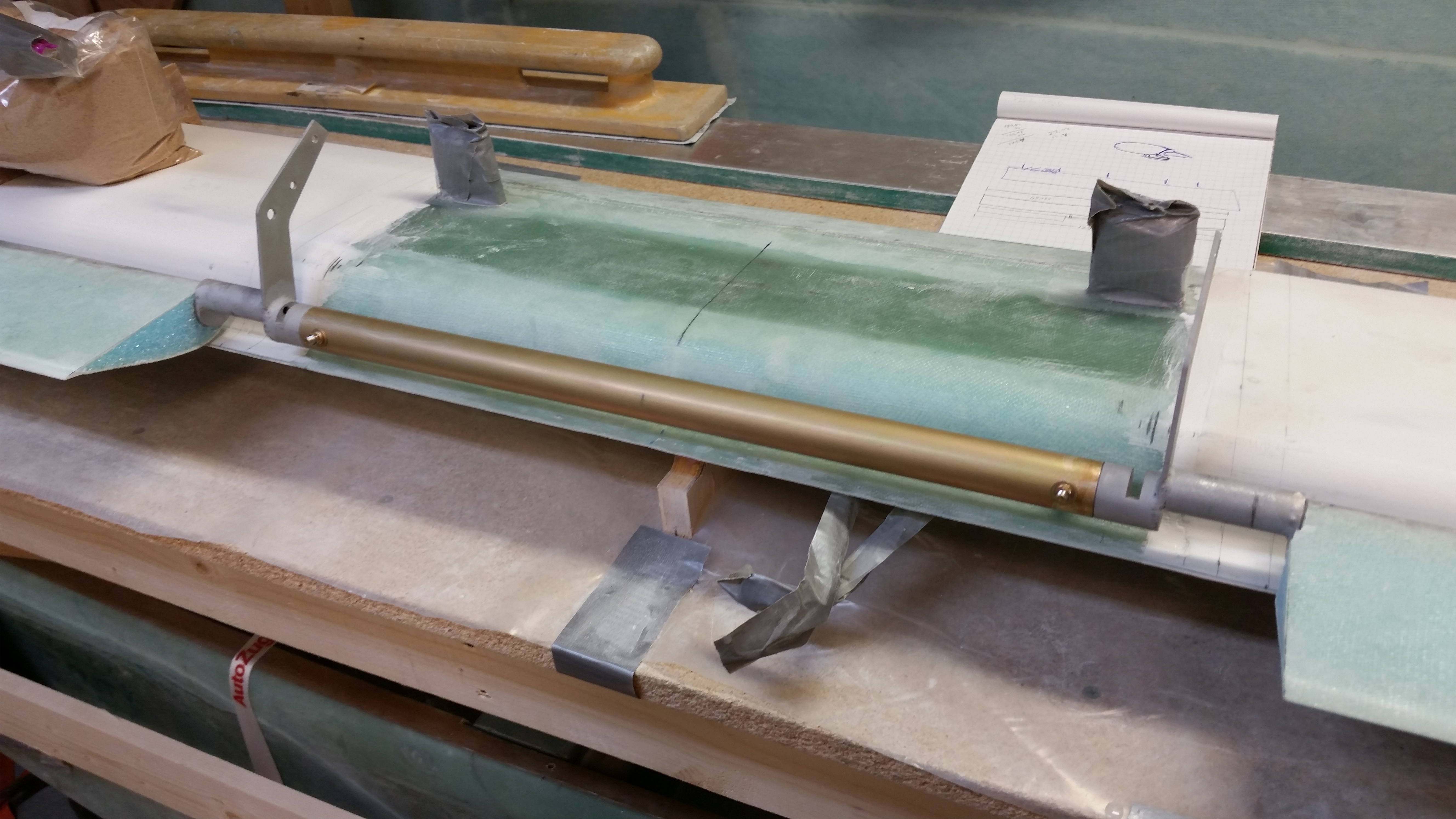
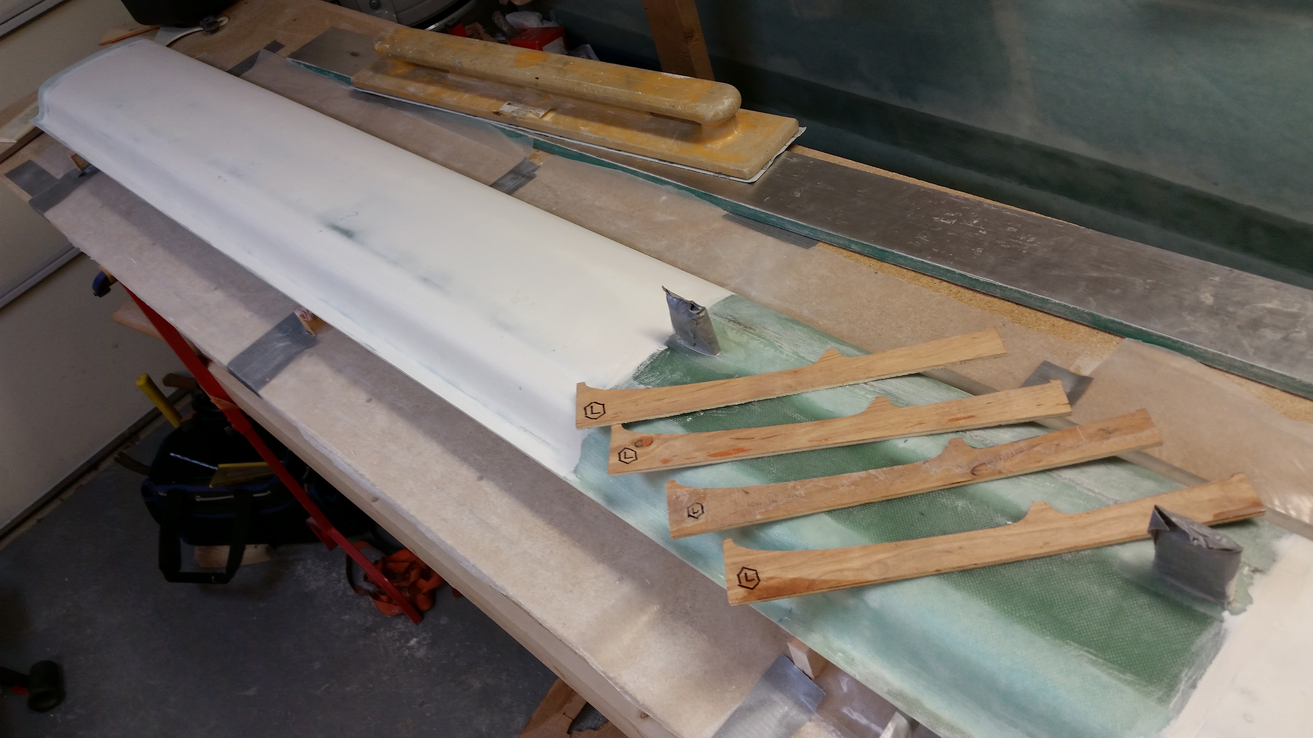
While the 3 floxed hinges were curing I started on some prep for the upcoming steps. First, I gathered up my outboard elevator weight positioning jig (“J” template), sanded the very rough edges smooth and ensured they matched the Roncz canard plans.

Verifying "J" templates

Thinking I was finished with the H100 6 lb foam after I build the canard, I sent it off to an EZ building buddy of mine before realizing this past week that I needed it to attach the outboard elevator weights.  Doh!  So I ordered some more from ACS a couple of days ago and it arrived today.

In addition, I traced out the Top Canard Contour Template “E” onto one of the 2×3’s I used for cutting the blue foam swoosh tips and made the first half of the top canard contour sanding block.

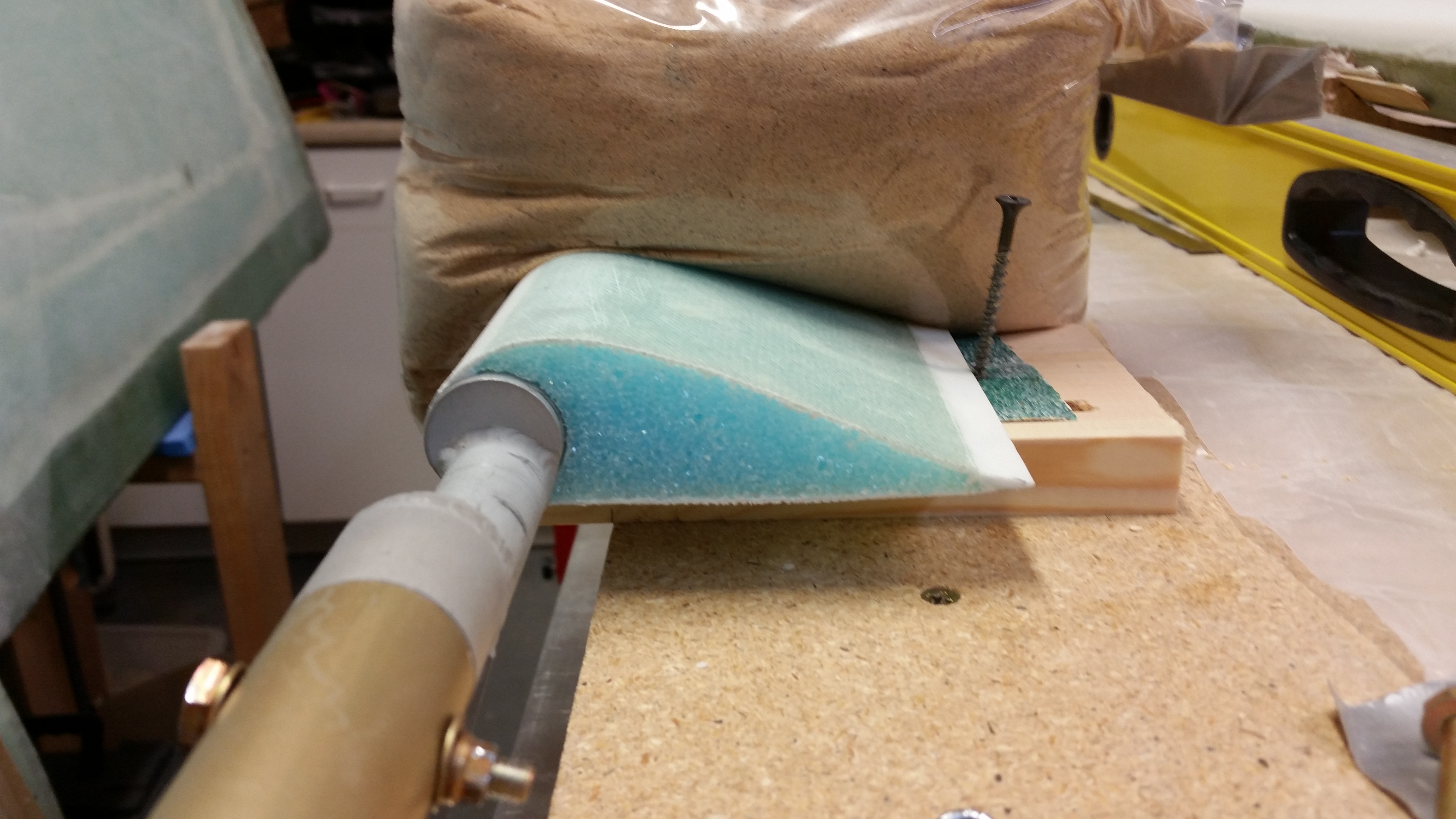
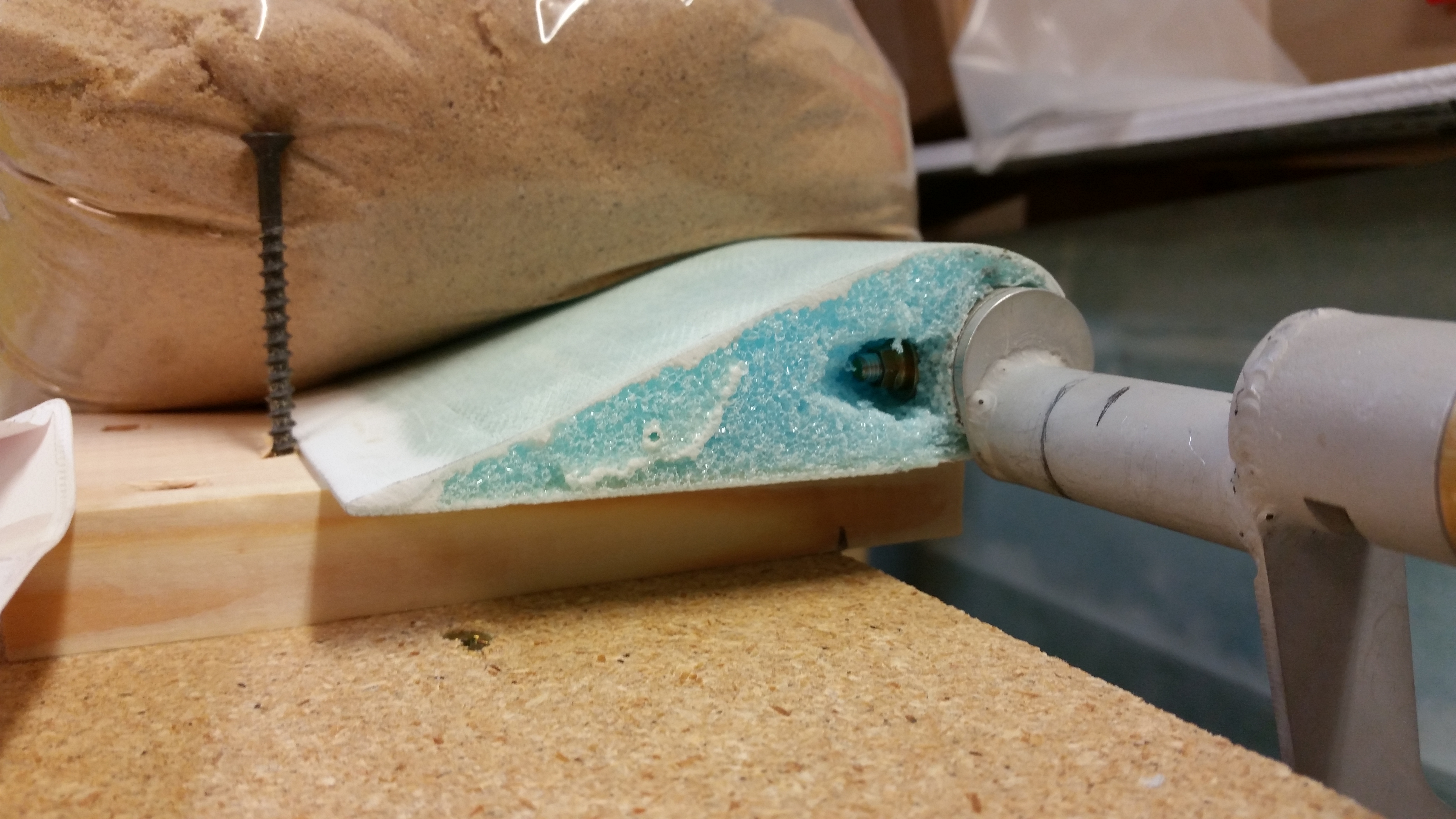
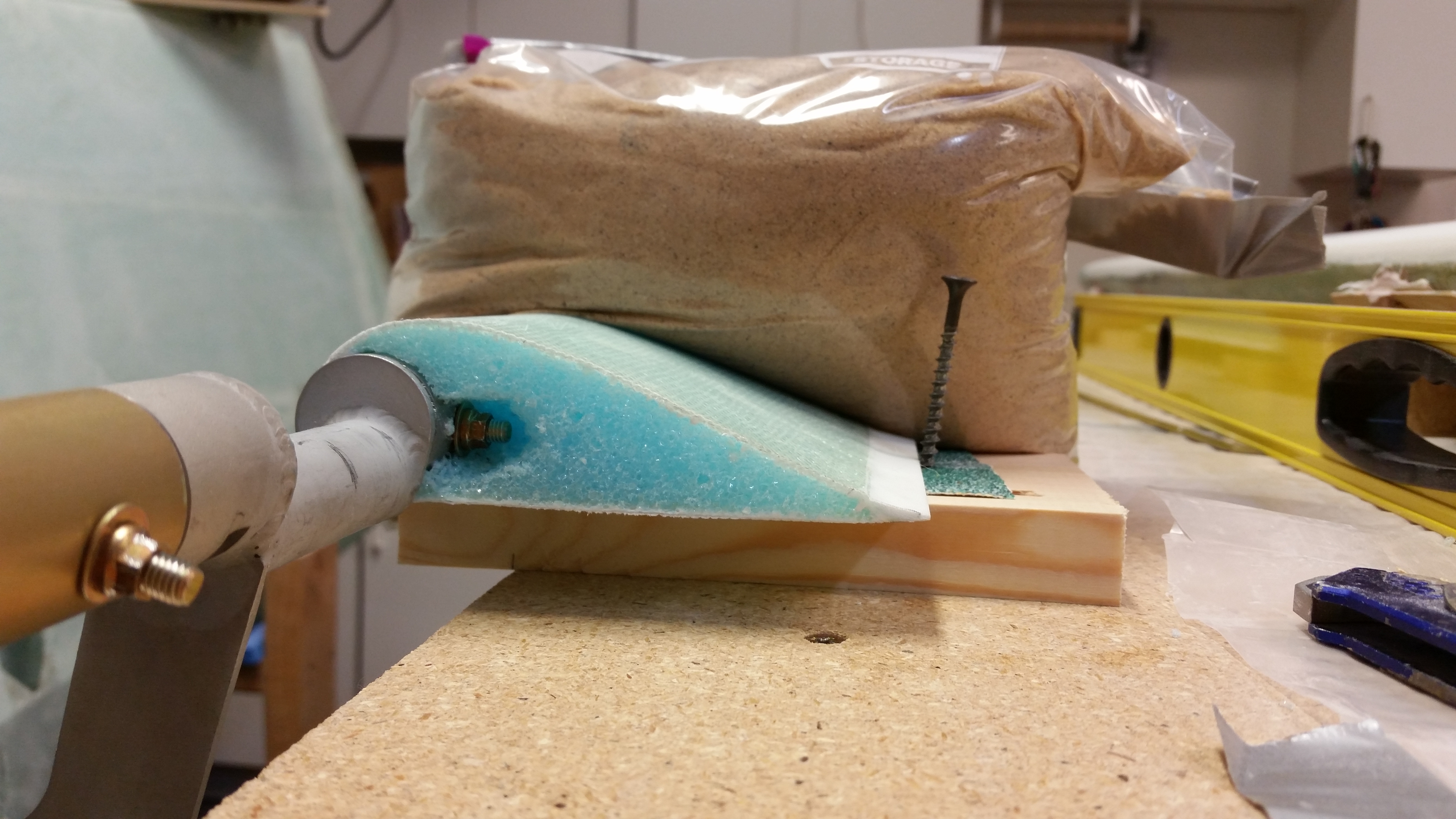
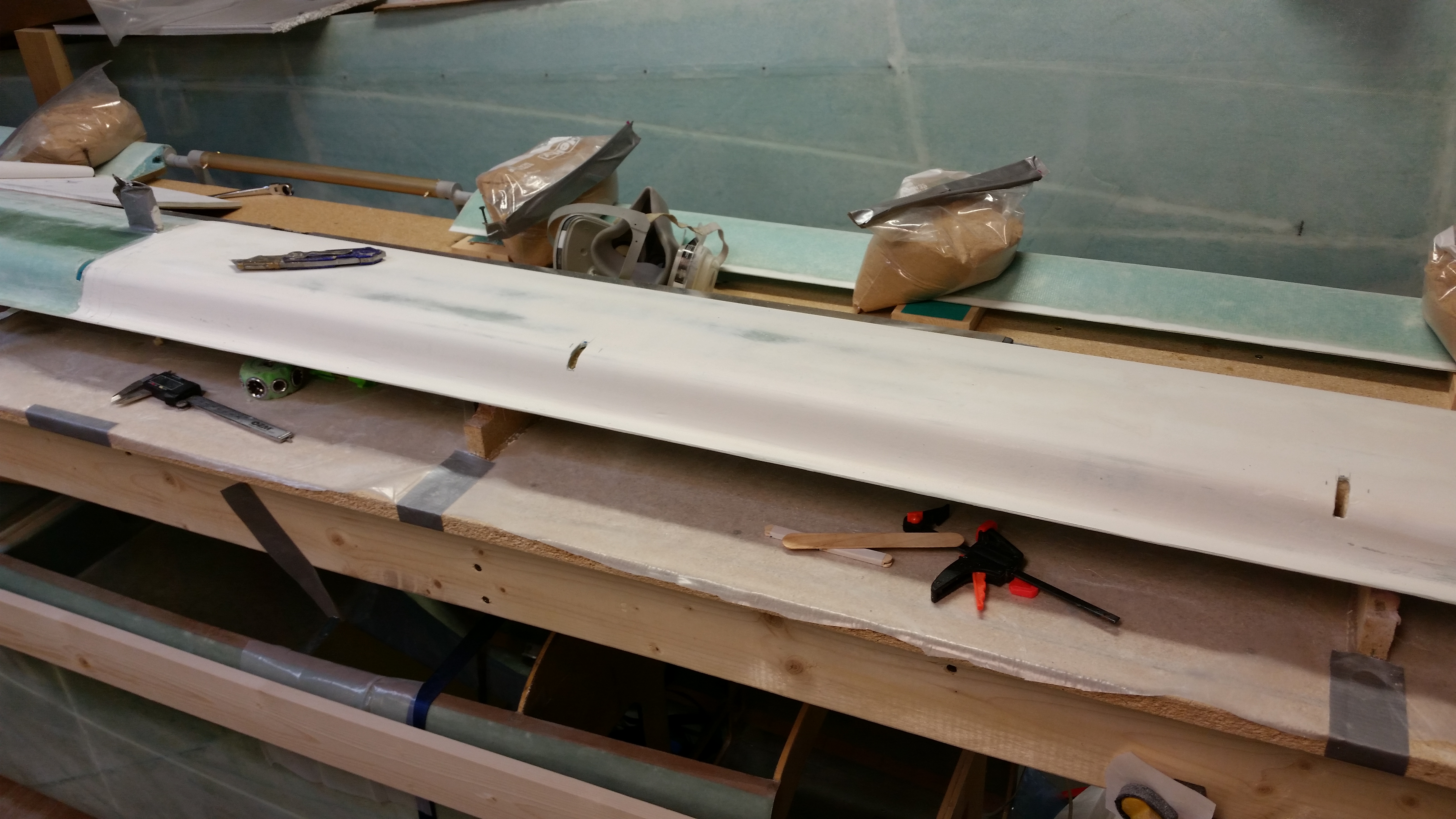
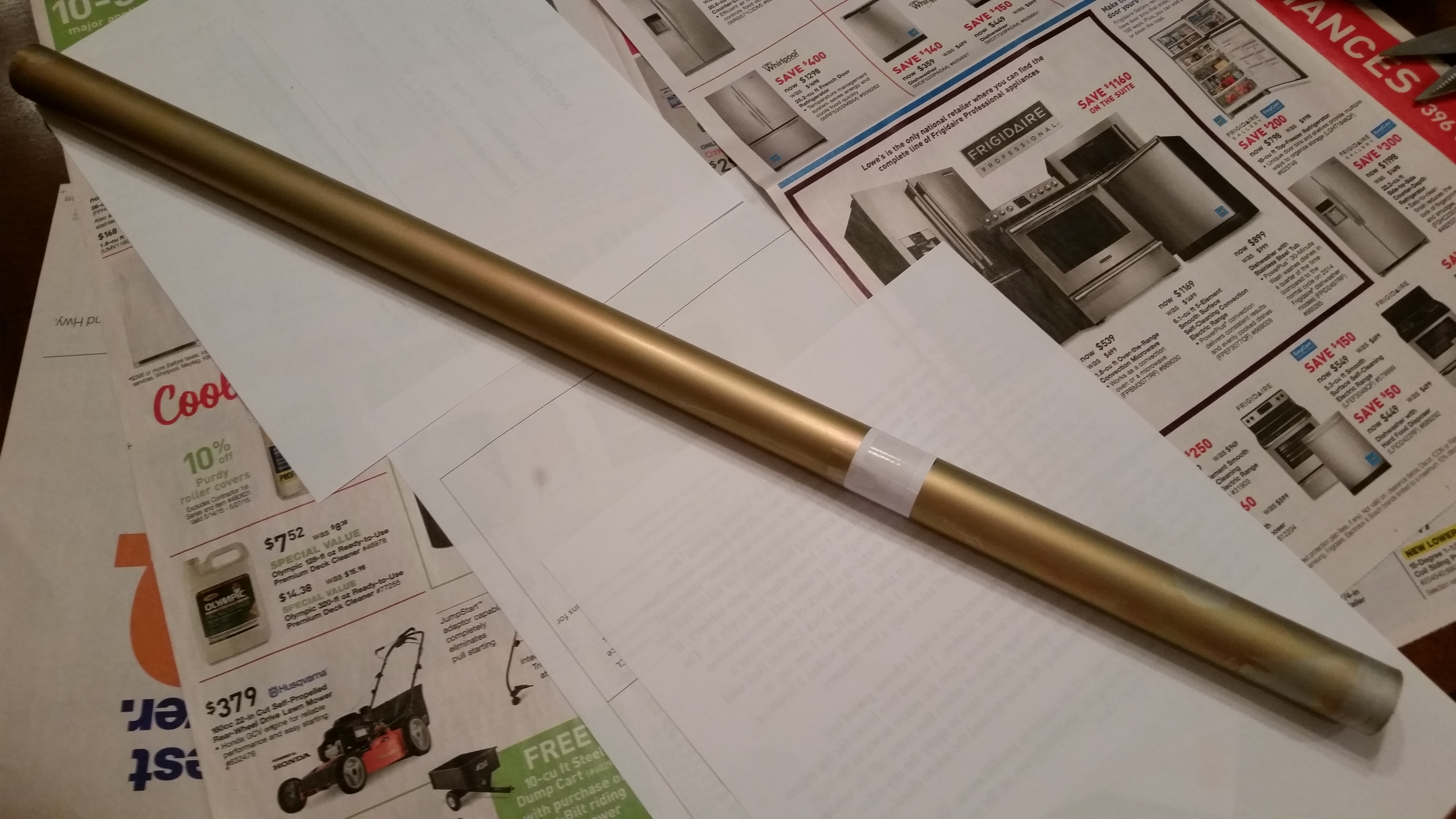
Finally, when I was at Home Depot yesterday I looked at buying a 24″ long piece of 4″ PVC pipe to sand the swoosh tip foam.  They wanted $8 for it and I wasn’t in the mood to spend that much on a one time use thing, so I simply recycled my 2″ OD PVC pipe that I used to Alodine the Spool Tube.  I attached a piece of 36 grit PSA sandpaper to it and plastic wrapped to allow the paper to fully stick to the PVC tube.

Bits 'n pieces

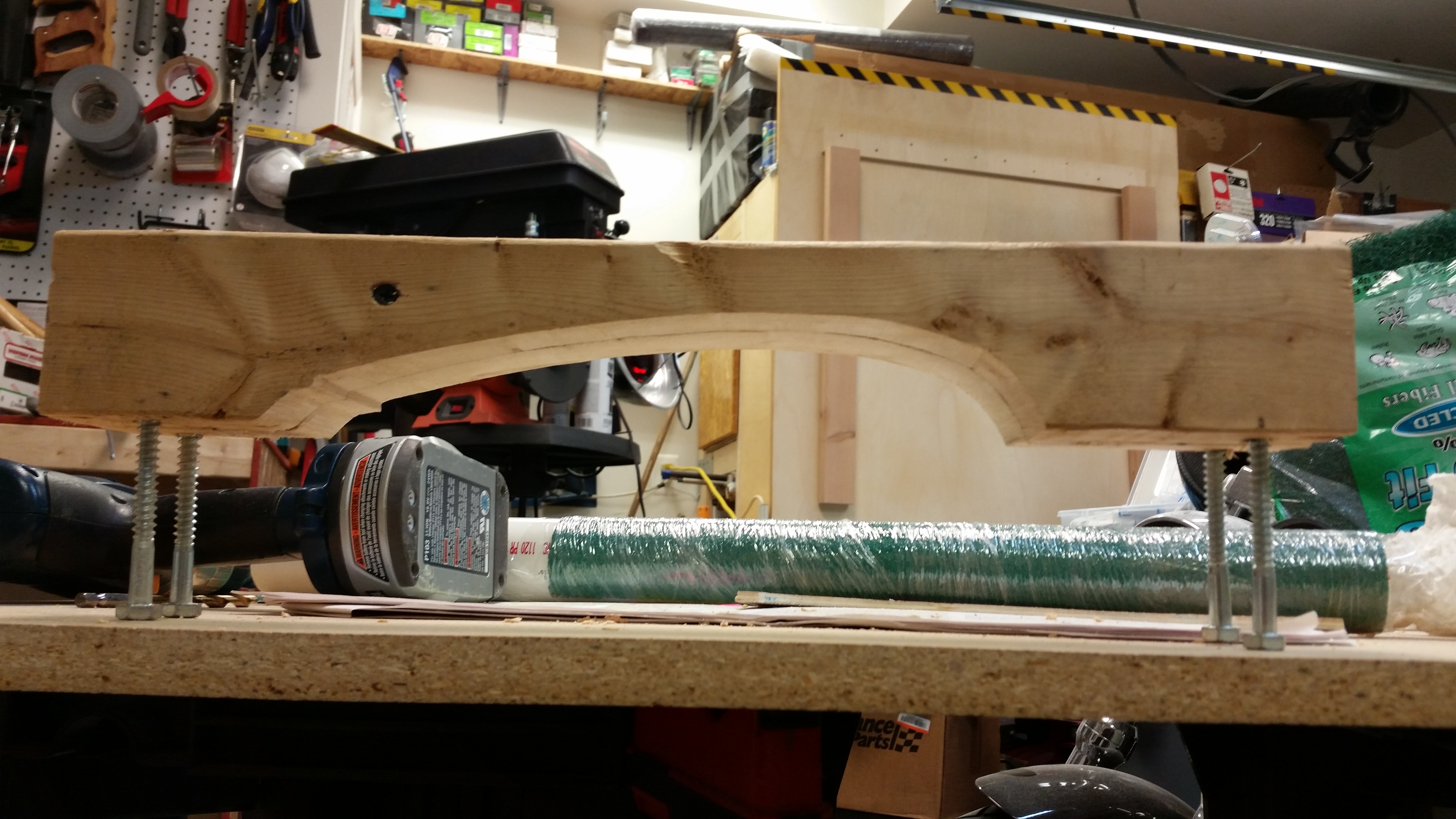
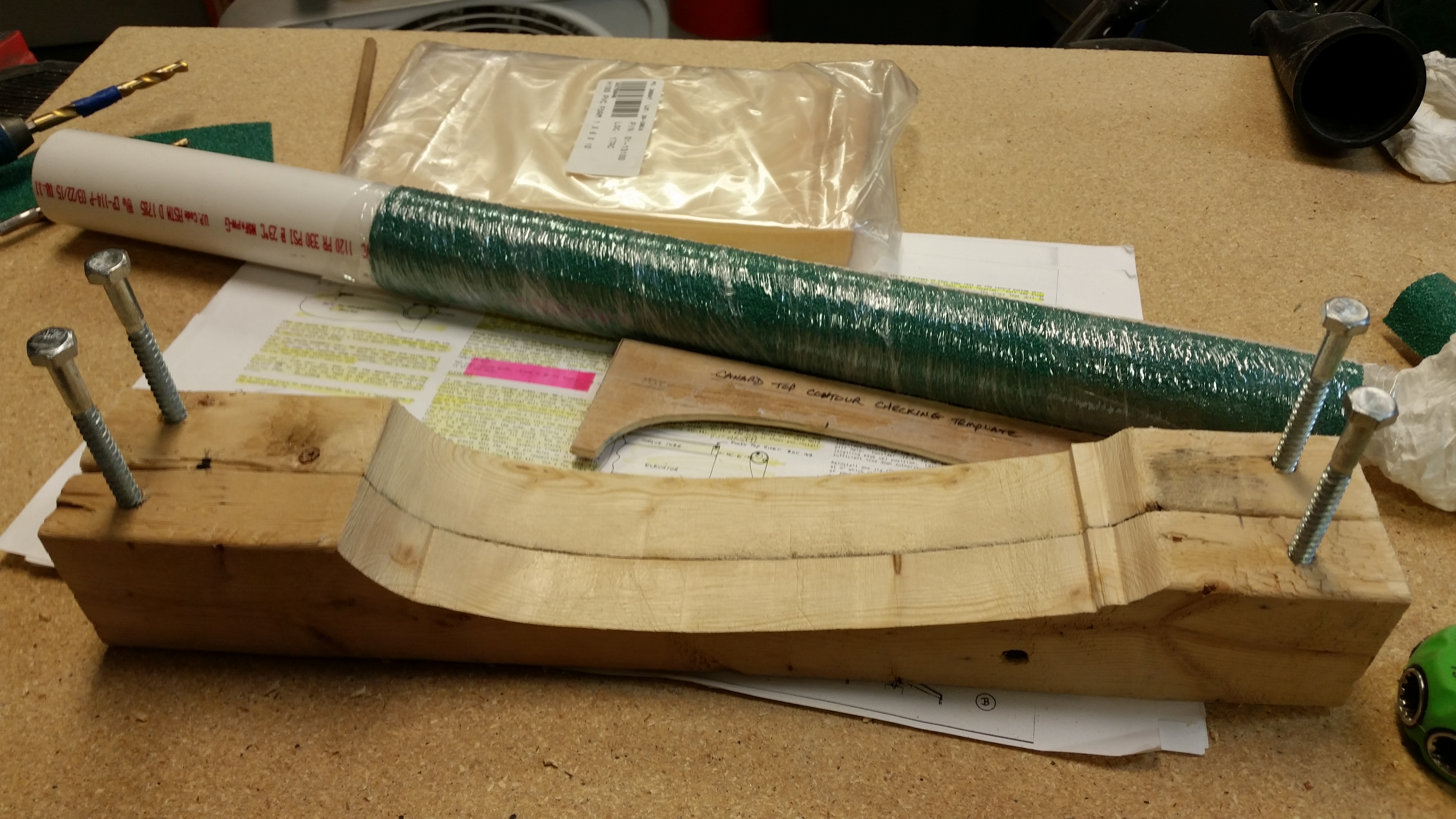
I then ripped the other 2×3 to 1.1″ wide, attached the two halves, gave the interior working edge a good sanding to get the surface evenly matched, drilled the lag screw pilot holes and then mounted the lag screw support legs.  As you can see below, the canard top contour sanding block is complete.

Top canard contour sanding block

Top canard contour sanding block

I did tweak the TE of the top canard sanding block just a hair so that my sanding of the canard top wouldn’t end up being a “let’s destroy the TE” party.  Last week I traced out the actual-sized profile of the canard from the Roncz plans to double check my progress. And as per my discussion with Mike at Feather Light, you may be able to make out that my TE on the canard is definitely just a tad higher than the Roncz plans outline.

Canard outline from Roncz plans

After a few hours of flox cure-time for the 3 hinges, I double checked the positioning and alignment of the elevators, pulled off the protective tape and cleaned up the dead flox goobers around the hinges.

Left outboard cured hinge tabRight inboard cured hinge tabRight outboard cured hinge tab

Last hinge… I double checked all the elevators’ positioning and alignment again, and everything looked great.  Since my prep tasks for the immediate upcoming steps were complete, and after floxing the last hinge into place all there was really left to do was let the hinge flox cure completely, I called my buddy Rob and made plans to meet for dinner, have a few beers and watch a movie.  I did one final alignment check and then whipped up some flox, using fast hardener like I had done for the other 5 hinges.  After I finished floxing in the last hinge (the left inboard hinge that attaches to the torque offset) I cleaned up the work area and then took the pic below.  I was just getting ready to turn out the lights and leave the shop when I decide to do one more check on the hinge.

And boy I’m glad I did!

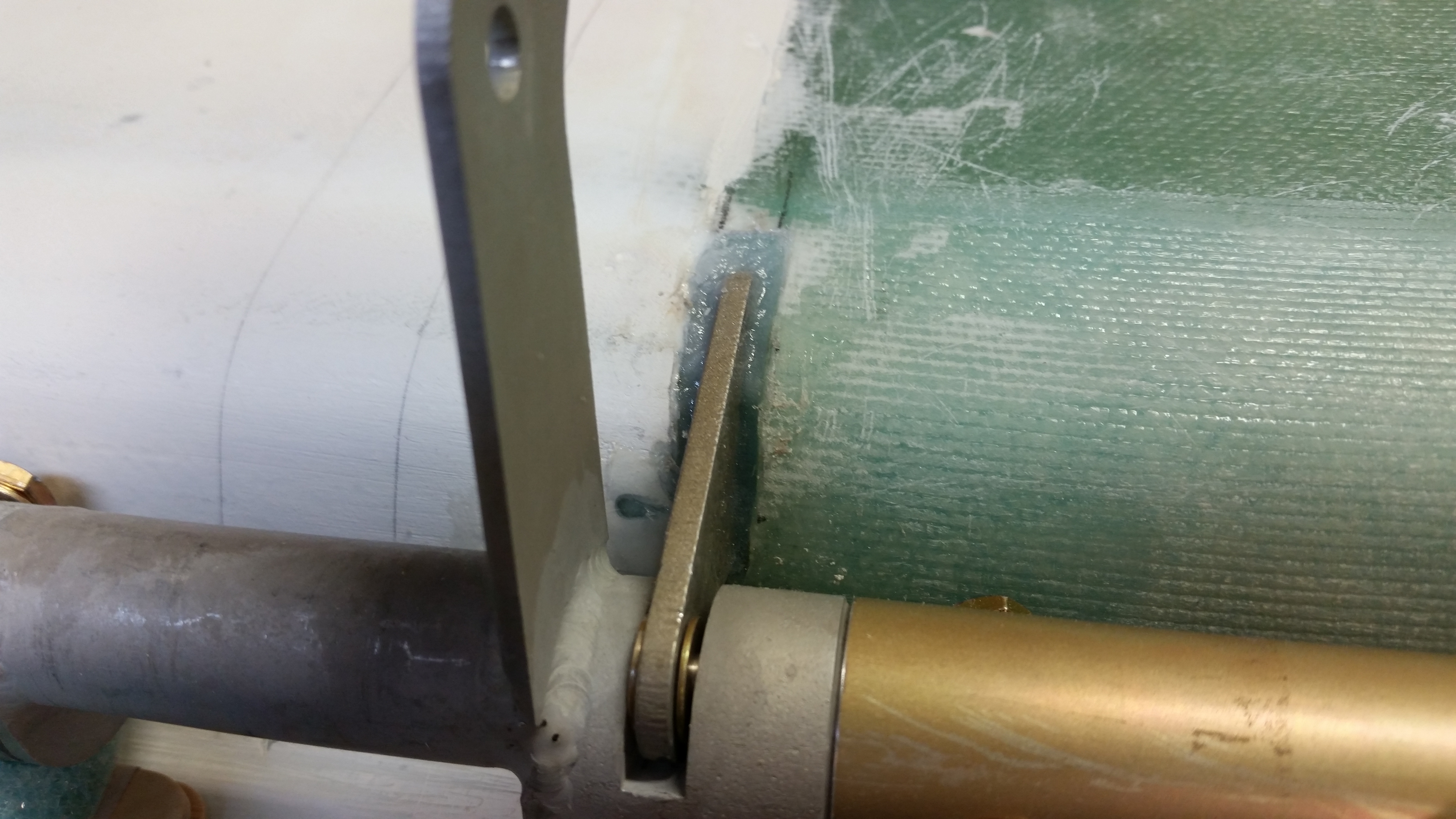
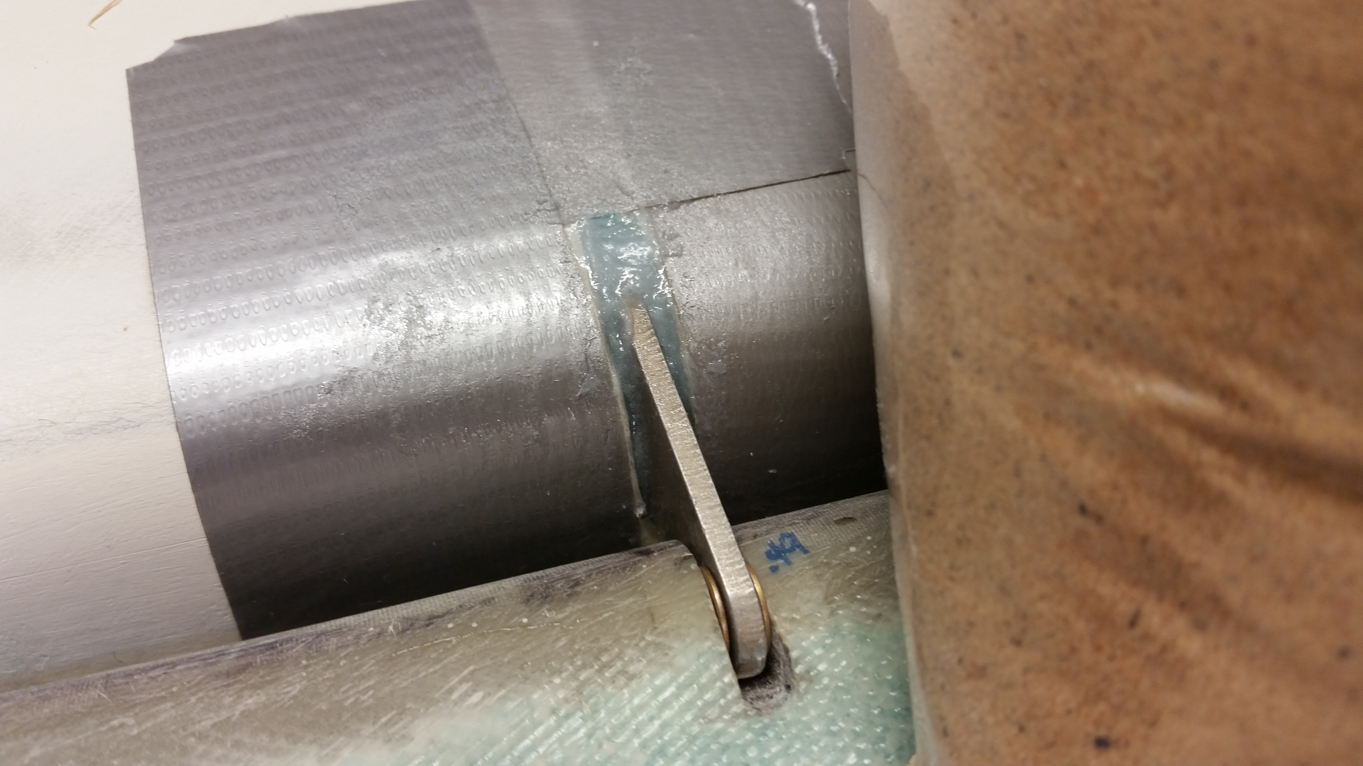
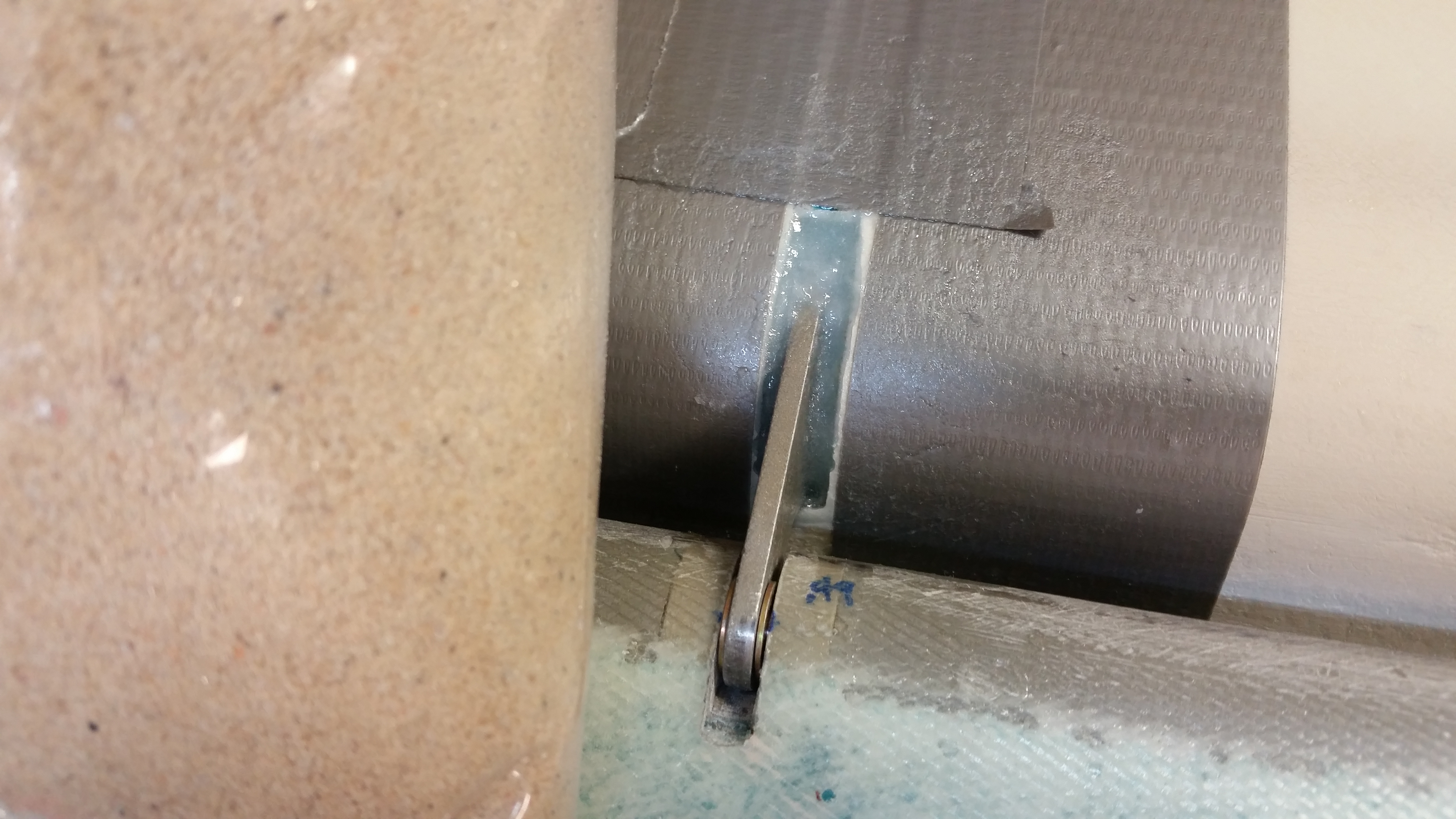
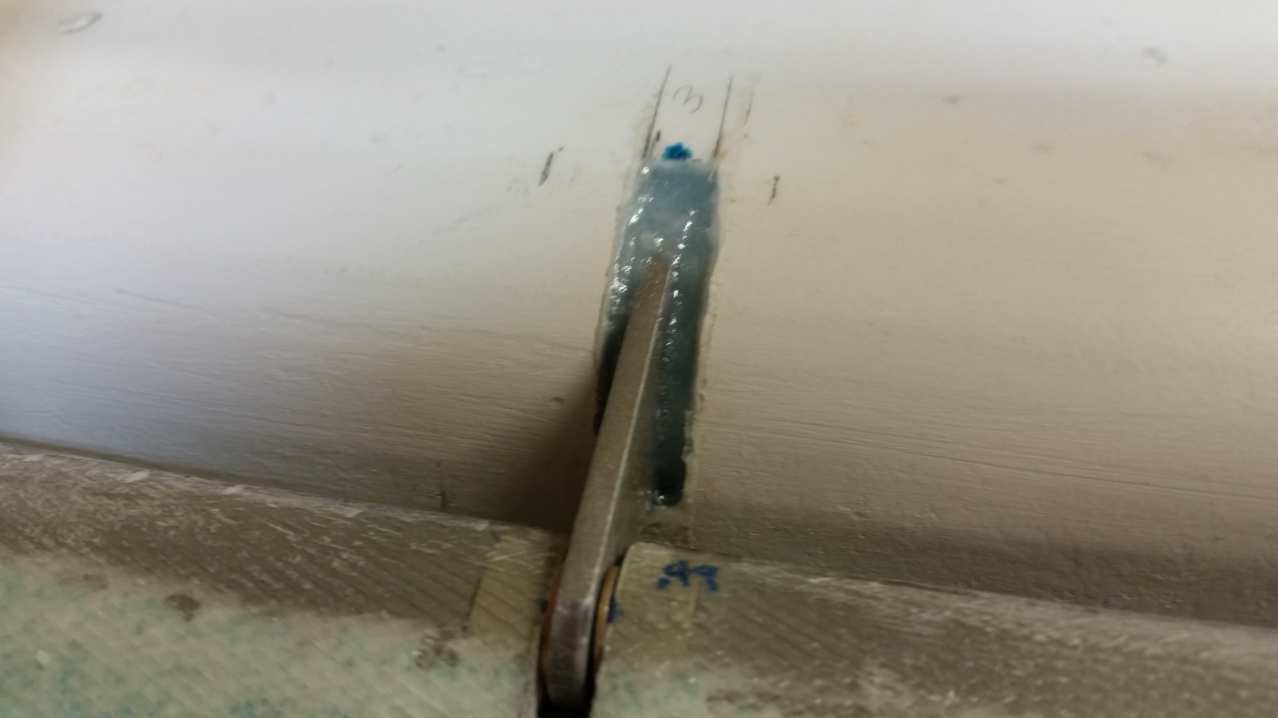
Since I moved the inboard hinges in about .2″ to .3″ from where I originally had planned for them to be installed, I was closer to the edge of the dense foam hard points that I installed before skinning the canard.  Being closer to the inboard edge of the hard point, I gouged an area out into the blue foam to make a small pocket of flox to increase the mass and strength of the hard point to make up for being so off-center in the dense foam insert.

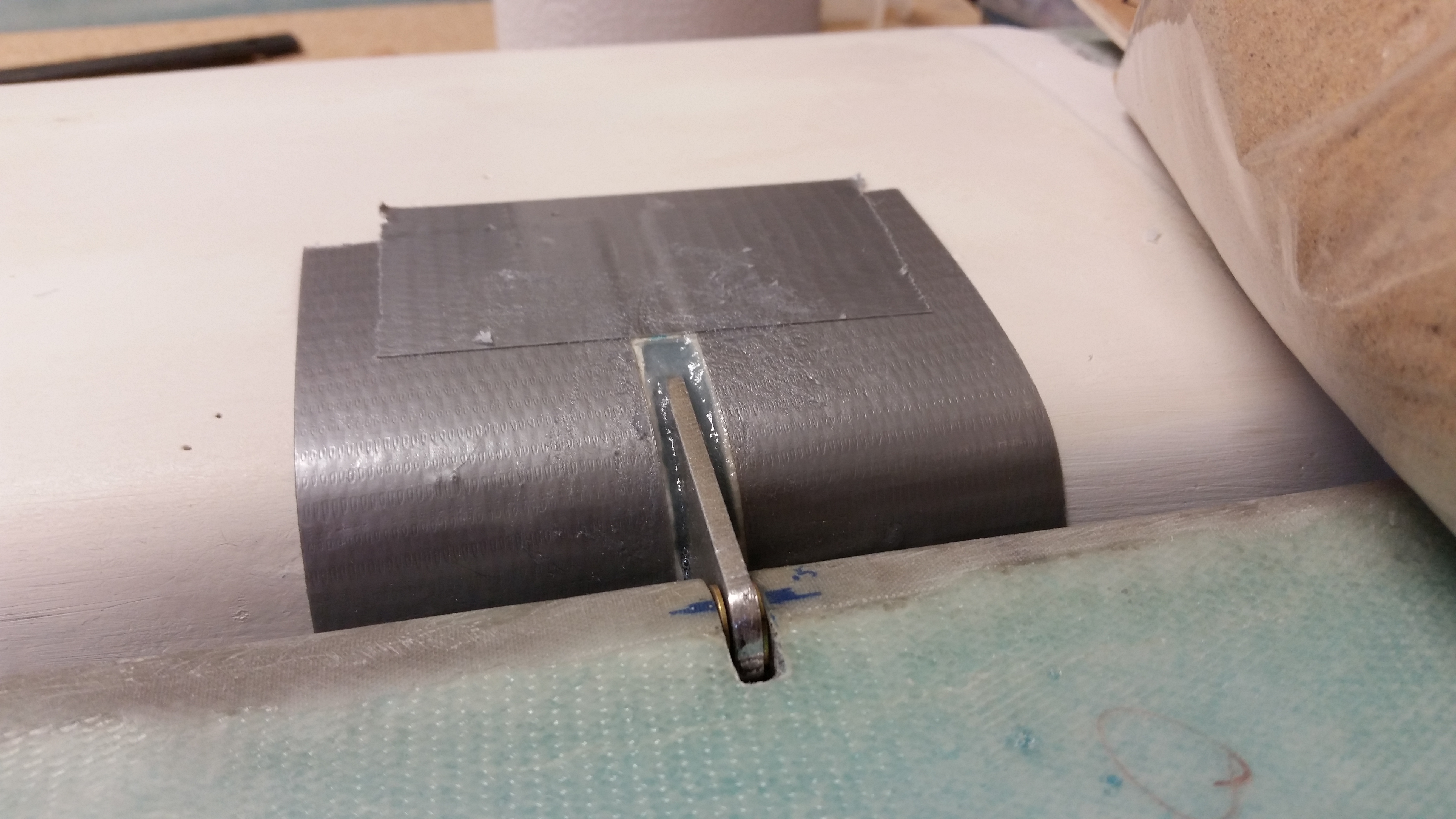
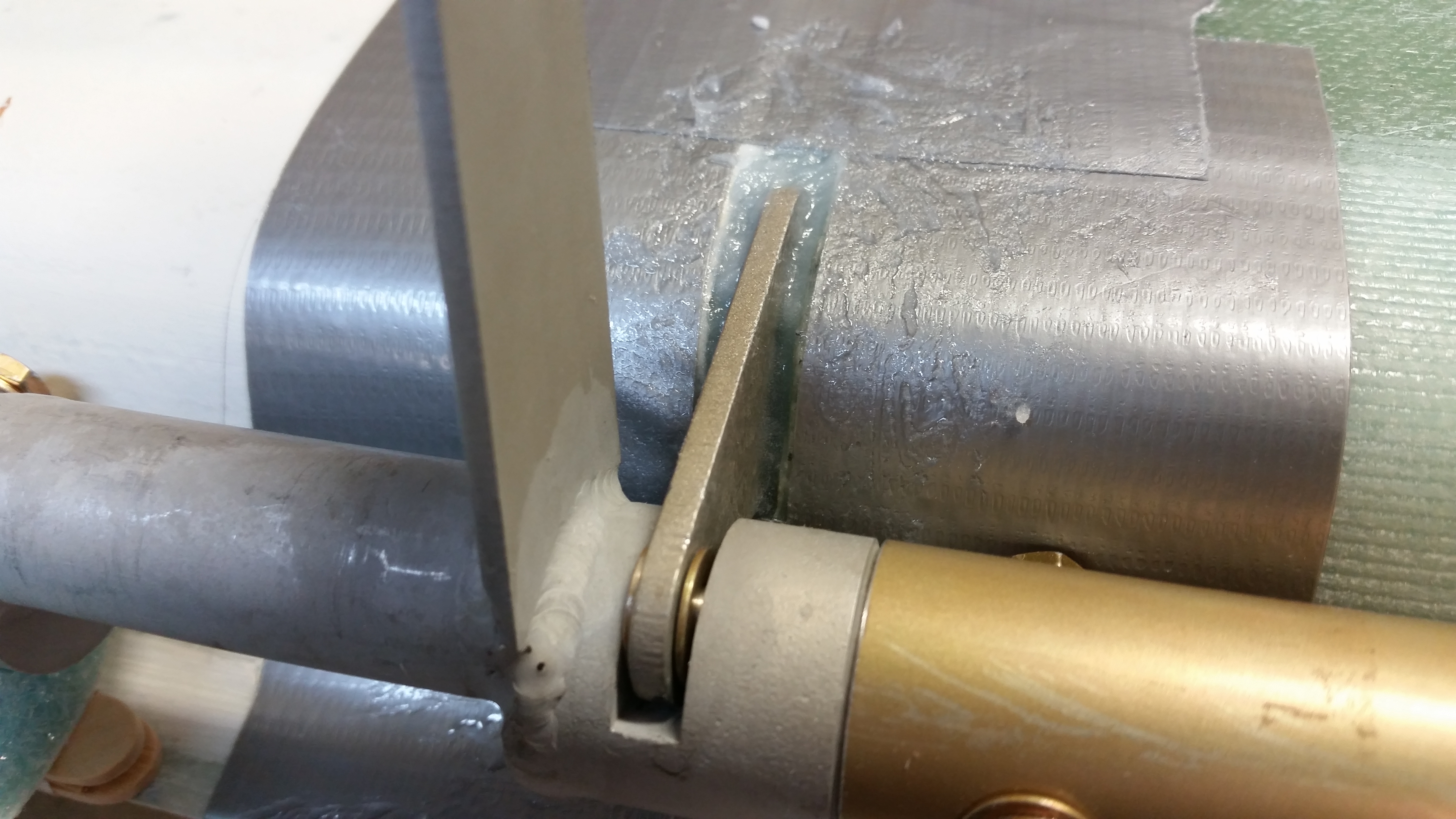
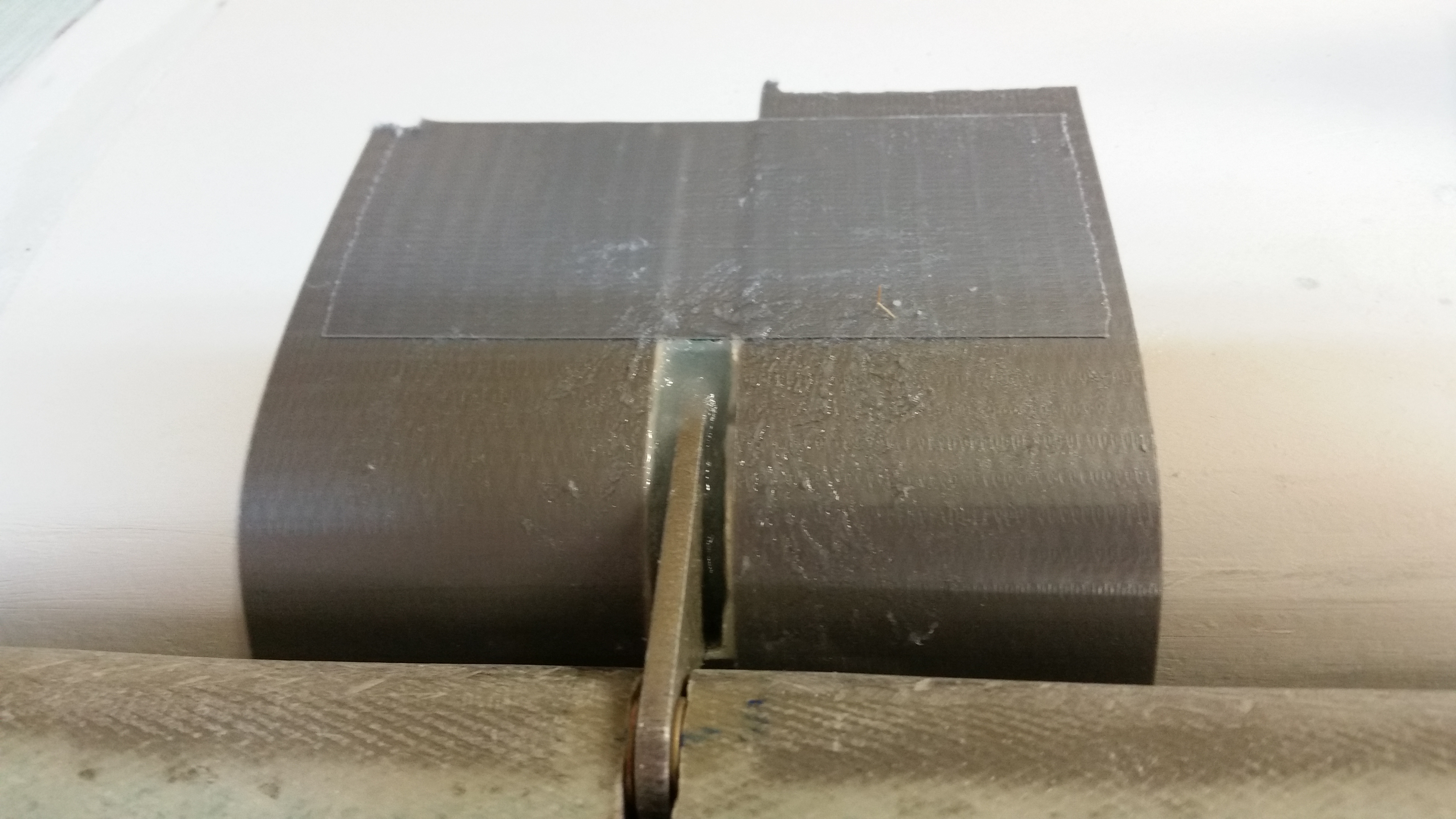
Well, with the right side inboard hinge there was no issue.  But on the left side, the only hinge I did this with, I started off by filling up the hinge slot with wet flox right up to the lower line of the hinge slot opening in the canard.  I then added some some more duct tape to make a tape “dam” about a 1/4″ higher than the bottom of the hinge slot bottom edge.  I then thickened the flox just a tad and then poured it in, filling up the rest of the hinge slot.

Due to my using fast hardener, at some point the extra mass of epoxy in that blue foam pocket, or perhaps there was an air bubble, or whatever it was . . . resulted in the a volcanic eruption of the flox back out of the hinge slot!  This occurred as I was cleaning up and I had no idea that it had happened.  There was enough flox that came out of that hinge slot (think baby spitting up!) that it enveloped the gap between the spool tube & canard, the connecting bolt & canard, and even some of the actual hinge & canard.  If I had walked out without cleaning that up I would have had an absolute catastrophe on my hands upon returning a few hours later!

At first I thought it was merely an air pocket that had burped for some weird reason, but as I was scooping all the flox back into place, I could feel that there was definitely some heat being generated.  Somewhere in the bowels of my hinge slot there was a exotherm event taking place.  I quickly grabbed my IR thermometer and checked the surface temp around the hinge slot.  The hottest reading I could find was just over 120° F, so I doubt if any foam damage occurred since at the moment it happened, while my back was turned, it puked out at least 50% of the flox that was in the hole and certainly allowed for a lot of heat to vent out at that point.  Moreover, the timeframe between it being good to then going spastic, to me scooping up flox puke was 2 minutes at most.

After getting the majority of the flox back into the hinge slot, I went upstairs to grab a very quick shower and change.  When I came back down to the shop less than 10 minutes later I was getting a temp reading around 88° and no more signs of disruption.  I cleaned up a little more around the hinge and took off.

Elevators installed

When I returned, all still looked good and no issues.  It definitely made for an exciting time on that final hinge floxing.  I looked all around the hinge area & underneath on the top of the canard for any discoloration or burn marks from the heat but thankfully couldn’t find any.  Thus, I’m closing the case of the volcanic hinge slot.

Once the hinges are fully cured I’ll double check the elevator alignment, gap and travel to ensure it’s all still good.  Then I’ll flip the canard and start working on the attaching, shaping and glassing the canard swoosh tips.


Chapter 11 – Eating an elephant!

There are a number of major tasks in building a Long-EZ that remind me of that aged old question: “How do you eat an elephant?”  And of course the answer is: “One bite at a time!”  Ahhh, true words in the realm of airplane building.  Thus it is so with mounting the elevators onto the canard.

My first task today was to review the plans and my notes.  I then went out to the garage and assessed how the elevators were looking in their mocked-upped state on the canard. It was immediately clear to me that the bottom edge of each of the elevator hinge bracket slots would have to be lowered.  These are the slots that I cut into the foam hard points on the canard last night.

After dropping the aft edge of each hinge slot, ensuring that I had a glass surface in the bottom of each slot, cleaning up the foam bits, and vacuuming the holes out, I remounted the elevator assembly to take a look.  Ah, much better!  The elevators were aligning much better and the gap between the elevators and the canard looked good, at least initially.  I stole a page from my good friend Dave Berenholtz’s build book by using shims to lock the hinges in place so I was free to play with the elevator movement and really get a good idea of my elevator travel situation.

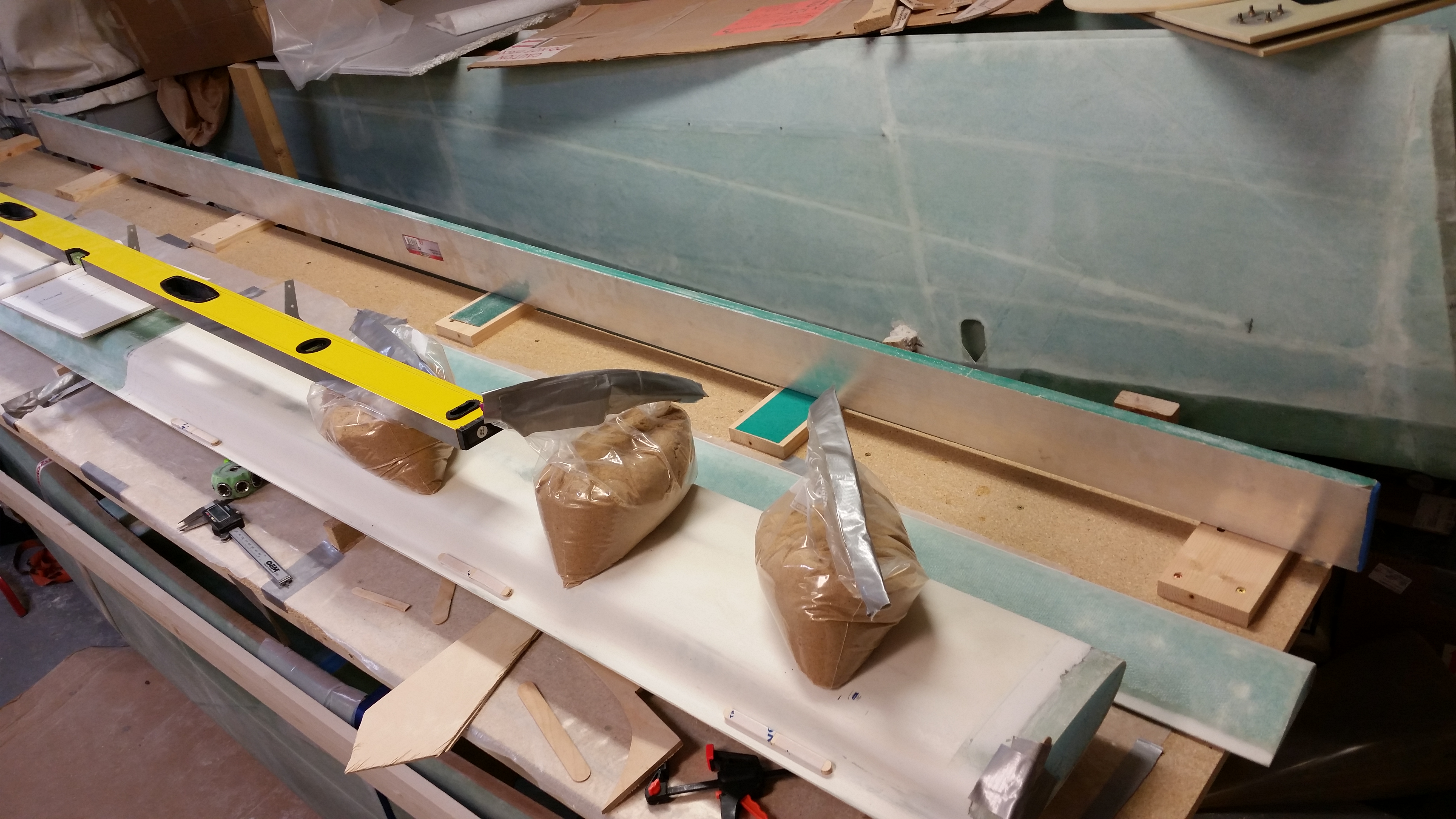
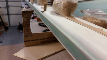
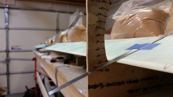
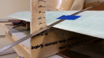
I checked the alignment between the two elevators to see if I had any issues.  Sighting down the TE of the elevators I was quite pleased that it looked like the TE was on rails as far as the alignment between the left & right elevator.  I tried to get a shot of it as best I could, thus the 2 pics below:
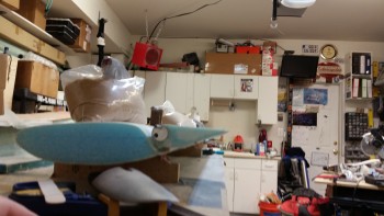
Elevator alignment

Elevator alignment

Before I went any further I gave Mike at Feather Light a call about the Canard TE and the interface gap between the canard and elevators.  Since Feather Light cut my canard & elevator cores, I wanted to discuss my slightly high TE as compared to the template in the Roncz canard plans.  My TE is just angled slightly less downward as it slopes aft, which makes the ENTIRE TE measure about 0.07″ higher than the diagram in the Roncz canard plans.  Since the fishtail on any aerodynamic surface is glassed first, this wouldn’t be an issue of my doing since I merely glassed the bottom of the canard first, which included the already shaped TE fishtail.  After a good talk with Mike I felt comfortable in keeping my gap wedges at 0.23″ thick, since this would: A) put the bottom of the elevators ever so slightly toward their original position as per plans, and more importantly B) still give me an appropriate gap, especially once the finish and paint is complete.  So, I pulled the trigger & moved on!

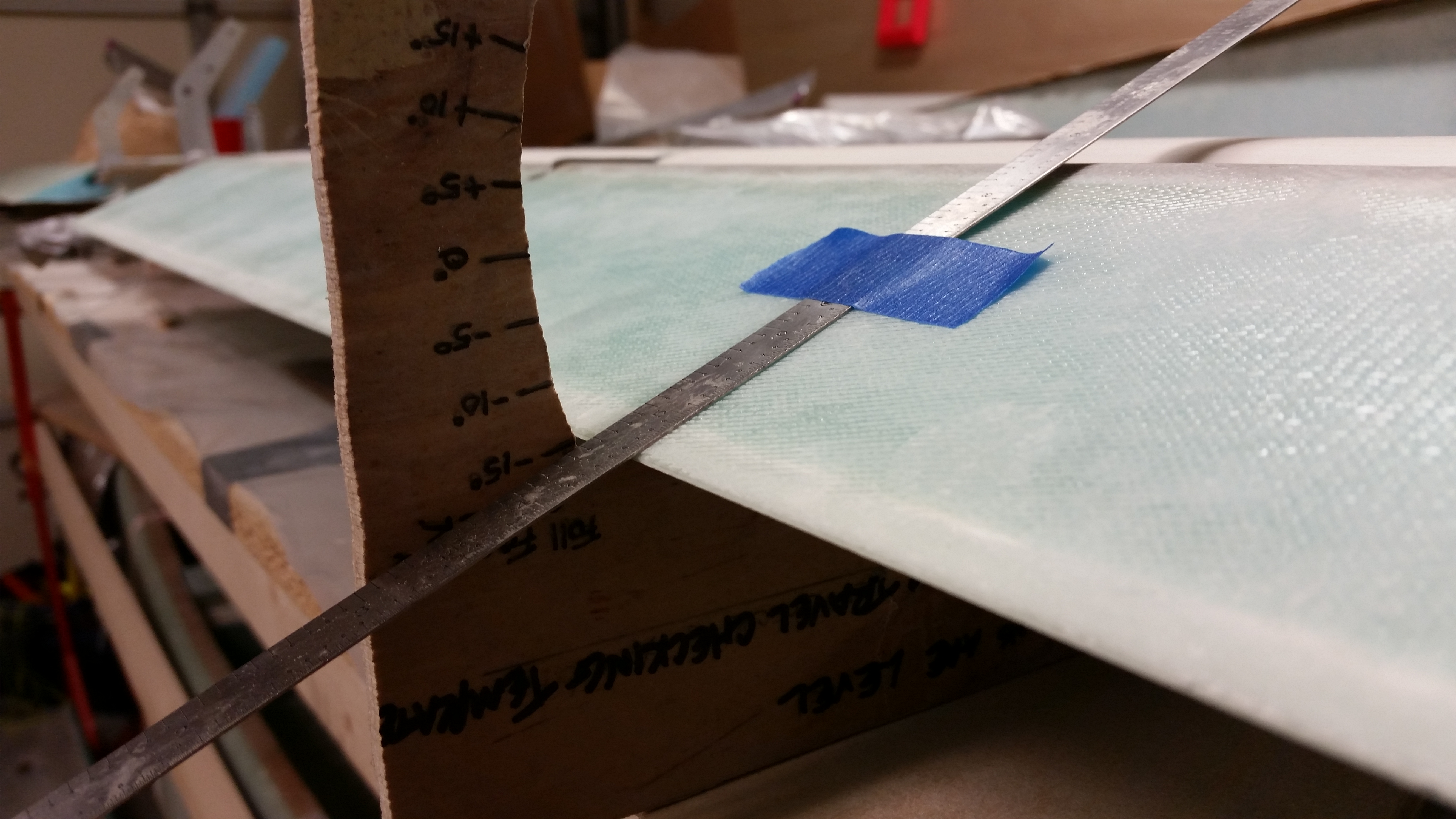
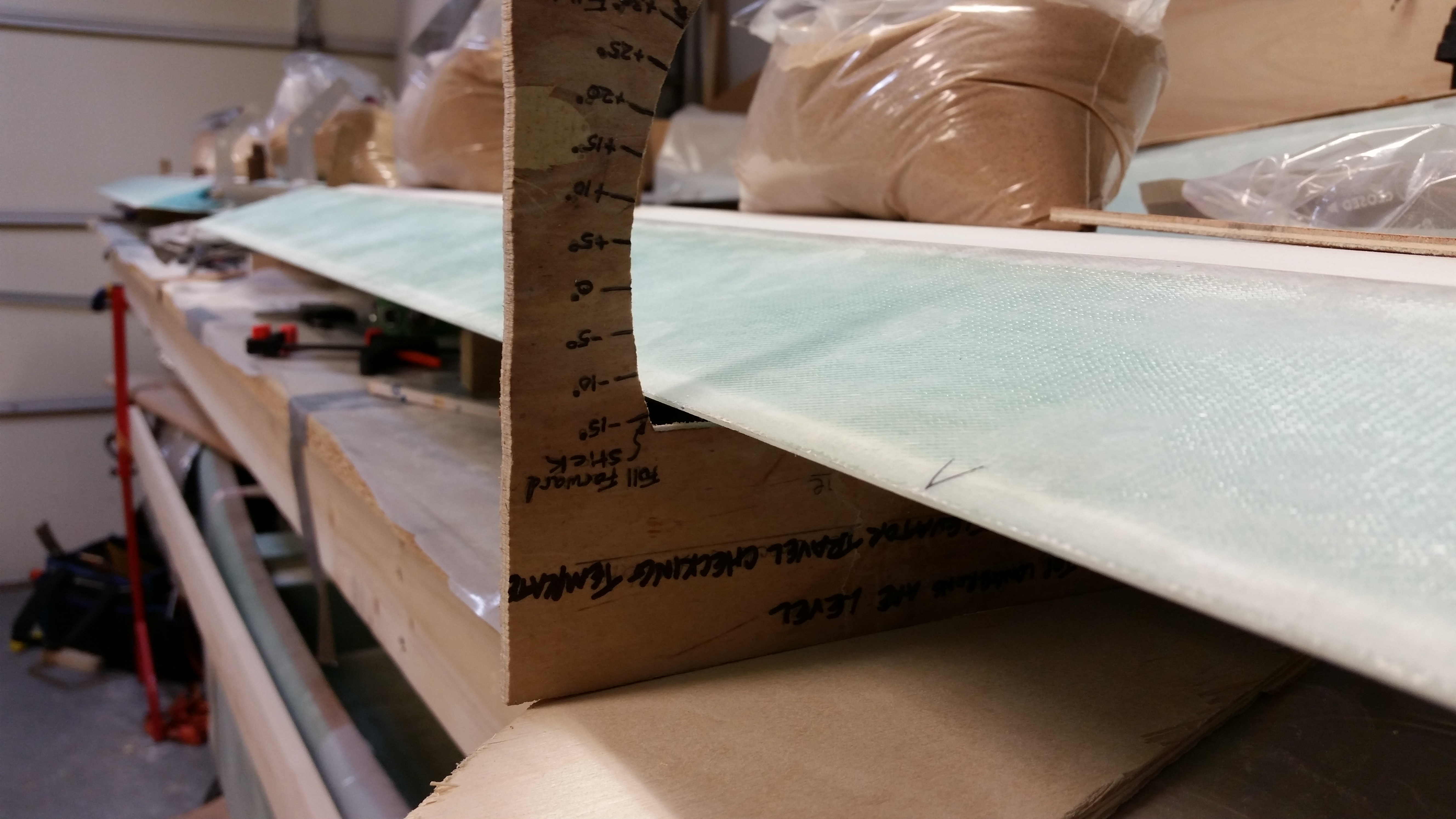
I then mounted the elevator angle template to see how I was doing on the elevator travel angles.  Of course the long pole in the tent when mounting the elevators is to ensure there’s enough up-elevator travel… otherwise known as the “ever-elusive 15° up travel,” or something clever like that!

As you can see from the pics below I was getting somewhere around a 13.5°± up travel. Of course this is already within specs as 12.5° up travel is the bare minimum, but since I was just starting out, I figured I could easily squeeze another degree from somewhere & get this thing close to 15°!
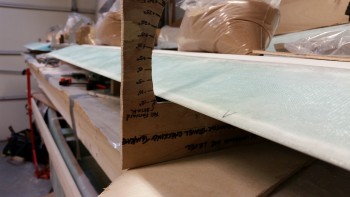
Elevator up travel

And to be clear, getting the max 15° travel really isn’t a pride issue.  I’m seriously just trying to be proactive since once the finish & paint go on, as well as the 2 plies of UNI for the outboard elevator weight, who knows how much that will reduce my up elevator travel.  So I want all I can get from the start.
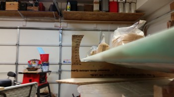
Elevator up travel

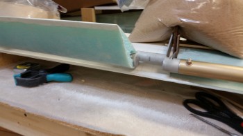
I found the culprit at the very inboard edge of the right elevator.  I locked the elevators in the up position by placing a sandbag on the torque offset arm (you can see it in the pic below) and then started sanding away with some 36 grit.
TE problem area

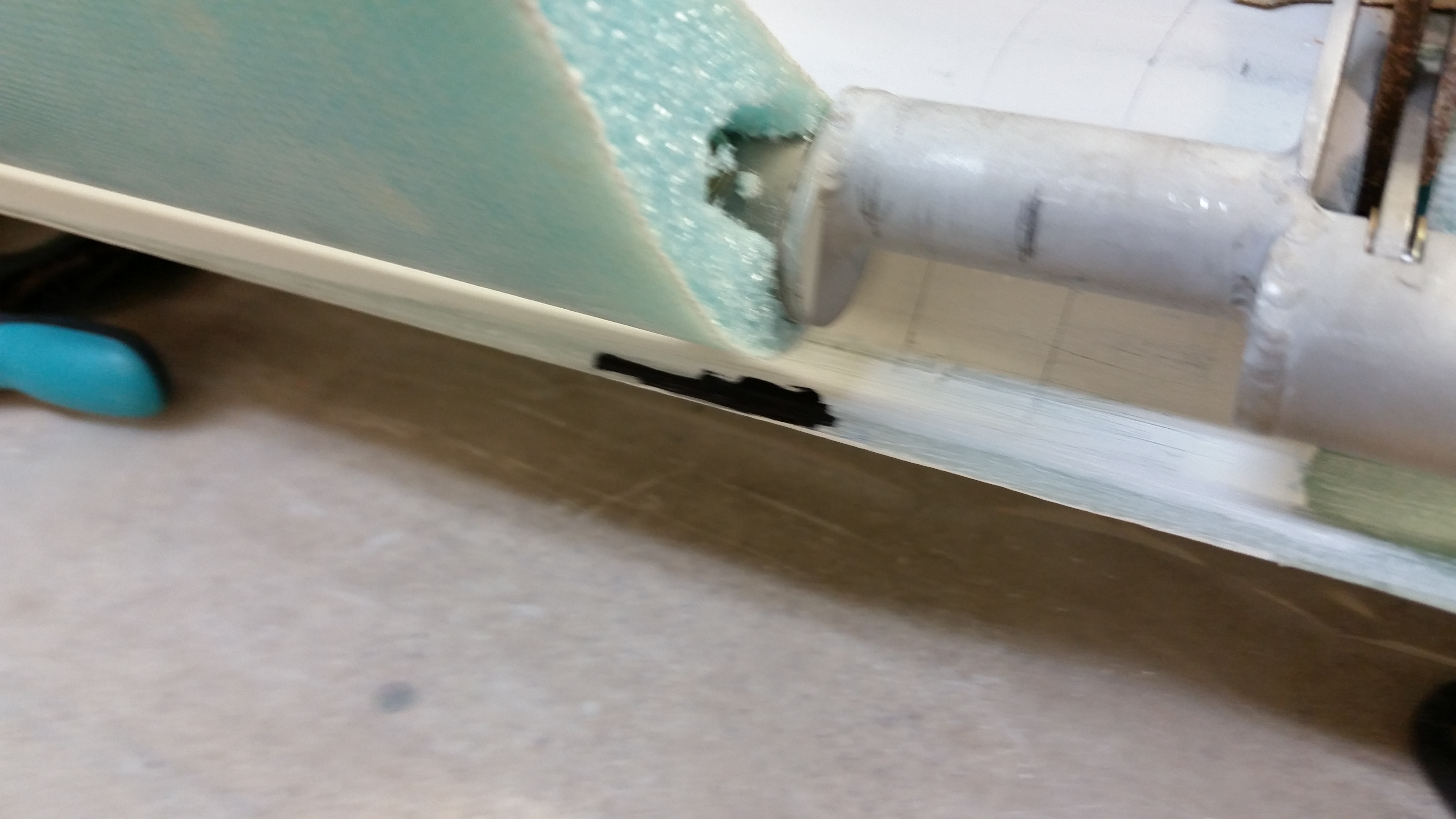
After a bit of sanding I tried the up travel again and only saw a slight improvement.  So I checked the gaps and position of the elevator assemblies, and then pinpointed the exact spot that was causing the issue.  I took a Sharpie and marked the offending area and hit it with another round of 36 grit, as you can see in the second pic below.
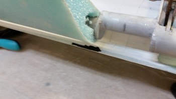
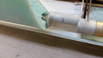
TE problem area

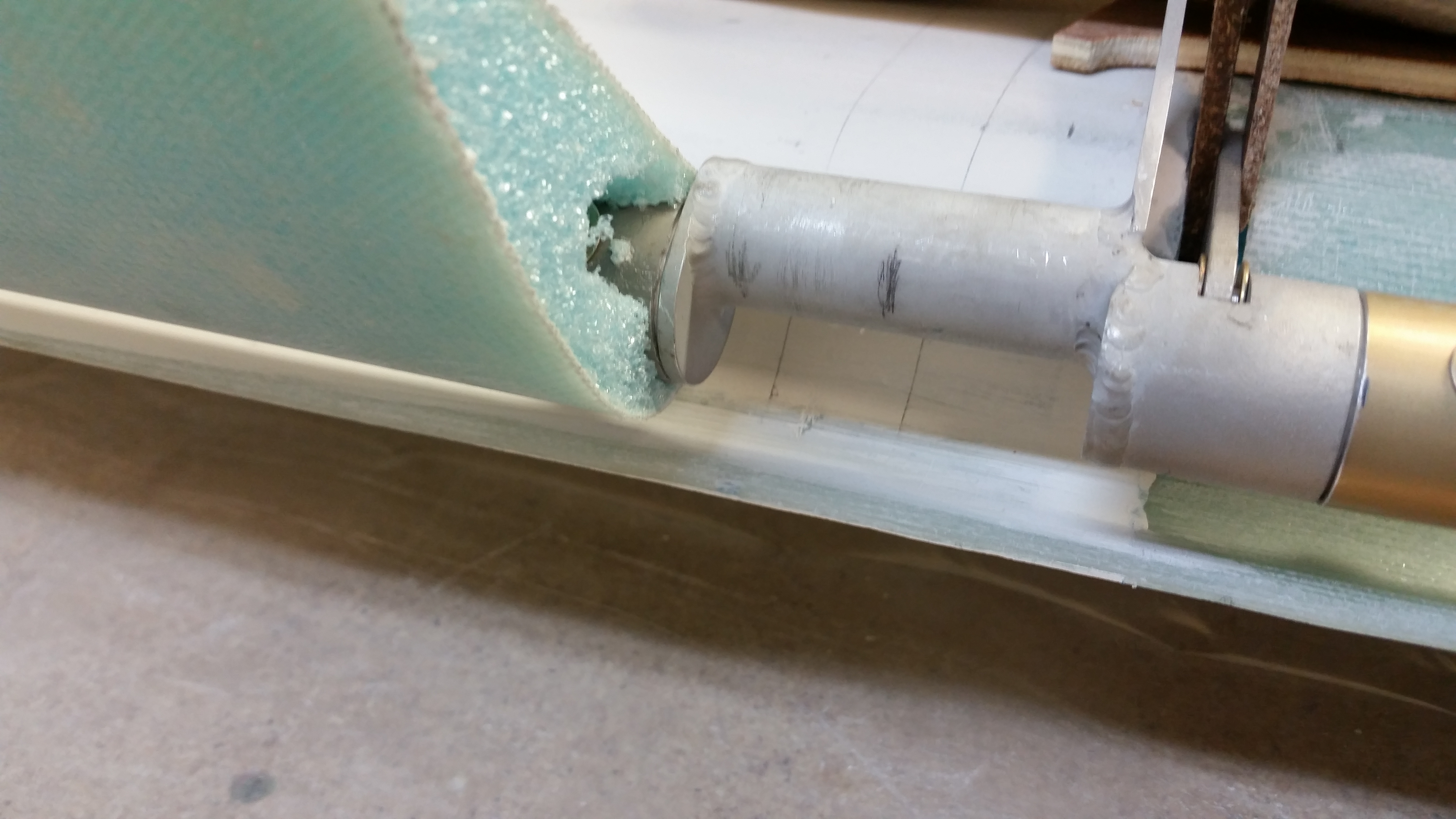
TE problem area sanded

I figured while I had the elevator locked in the “up” position (of course it’s really in the down position) I would grab a couple shots.
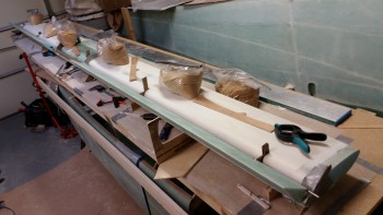
Elevator down travel

Elevator down travel

Clearly I have no issue with my down elevator travel!
Elevator down travel

And now I’m good on my up elevator travel!  I always say that there’s no problem in this world that can’t be fixed with 36-grit sandpaper . . .  ha!
Elevator up travel

I moved the elevator degree template over to the other side and am still getting about 14.7° up travel.  Not sure why the difference since I rechecked my gaps, my “L” template spacings, and left/right elevator TE alignment.  Could just be a combination of factors, but since everything else is lining up well, I’m calling this good.

A thought I had on the inboard problem area causing the limit in up elevator travel is that if I go with a decent fairing at the elevator root then I could simply eliminate the problem area. I’ll keep that in my back pocket in case I need it later on.
Right side elevator up travel

Here I’m simply comparing the “Zero” elevator in trail on the degree template vs. the zero trail on the “L” template.  I already knew there was a very slight gap on the “L” templates towards the TE of the elevators when I checked them against the Roncz canard plans diagrams, but I was curious how these matched up.  They’re only slightly different, but close enough to get the kinks worked out when I rig the elevator control system later on.
0 degrees trail

Elevator "0" position

And here’s a wide-angle shot of the elevators in the up position.
Elevator "up" position

I spent about 45 minutes checking the elevators and spool tube assembly for alignment.  I took out my über gut German aluminum straight board to check the TE alignment.  My right elevator was just a tad off with the inboard more aft than the outboard end.  When I checked my “L” template alignments, I realized that perhaps working the elevator up & down had caused the right inboard hinge point to be off.  So I went back and rechecked every gap spacer and “L” template for elevator vs canard spacing, and then did a TE check again.  I checked my elevator travel again and it all looked great.

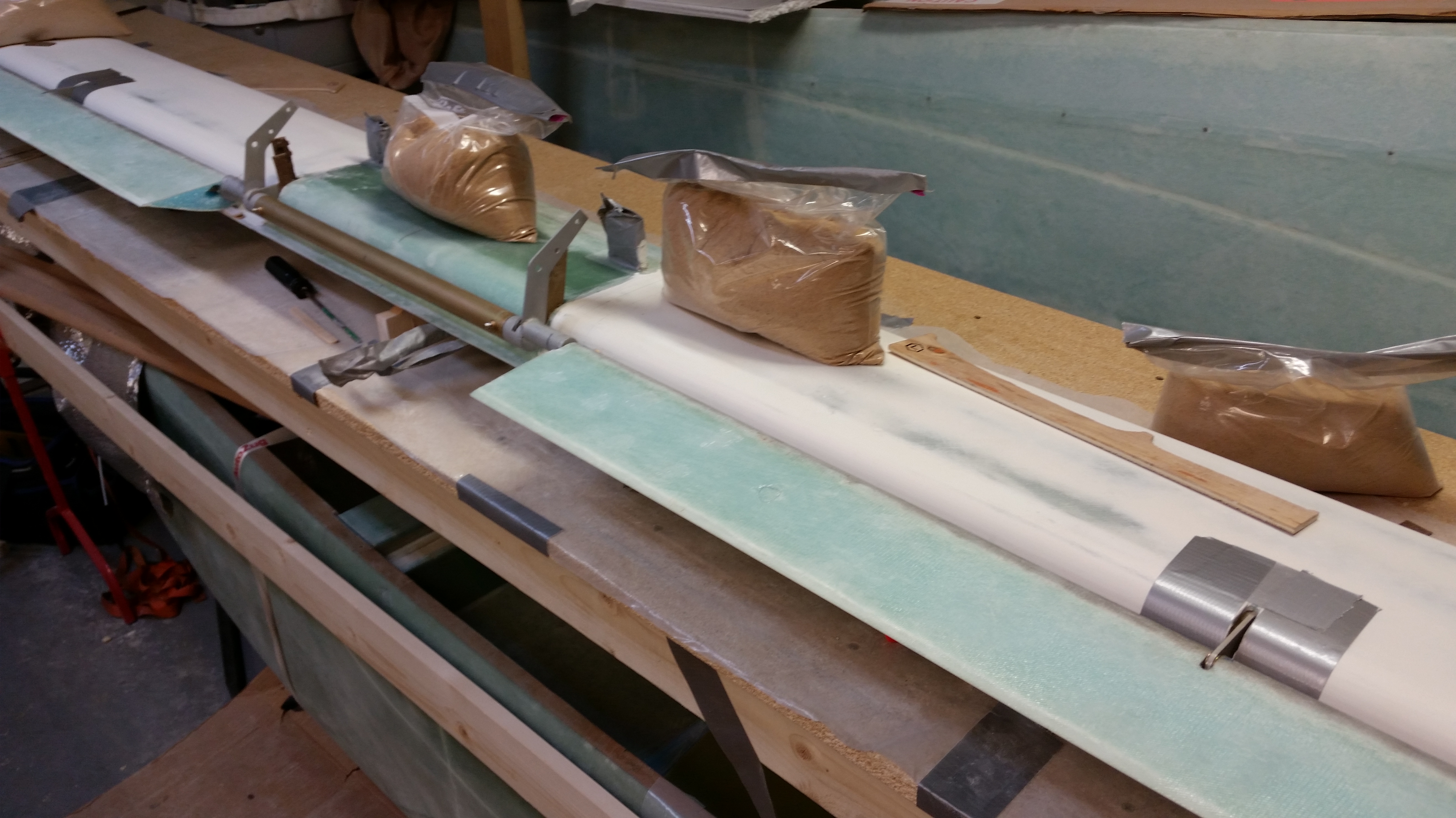
I stole yet another play out of Dave Berenholtz’s playbook and instead of floxing all the hinges at the same time, I wanted to ensure that I install the elevators in one calculated step at a time.  Thus, I taped the areas around each of the two middle hinges of the left and right elevators, respectively as you can see below.  This gives me a midpoint fulcrum, if you will, to ensure that the the outboard and inboard hinge areas are perfectly set when I flox them into place.
Prepping middle hinges for flox

Also, I noticed that the gap between elevator and canard TE in the middle of each elevator is about 30 thou greater than each end of the elevator.  After looking at this for a bit, I concluded that it’s most likely hot wire drag when they cut the foam cores.  I point this out because I also noticed that if I just added the slightest bit of pressure on top of the elevator (as it sits now) that the gap almost completely closes.  I then tried adding a little weight to the midpoint areas of each elevator and sighting the TE from end to end: no discernible negative affect on TE alignment.  Thus, in each pic below you’ll note that there’s a sandbag next to each middle hinge point as the hinge is getting floxed into the slots on the canard.  And again, we’re talking maybe a total movement of 15-20 thou when all is said and done, so I don’t see the hinge swing geometry getting all wonky either.
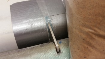
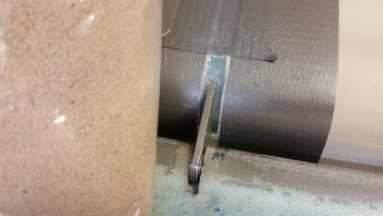
Floxing middle hingesFloxing middle hinges

Fast forward 5 hours later and here are the two midpoint elevator hinges mounted in the canard, after I cleaned them up.
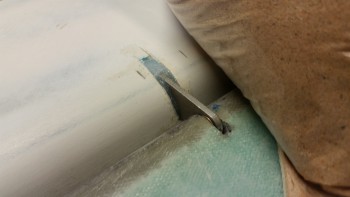
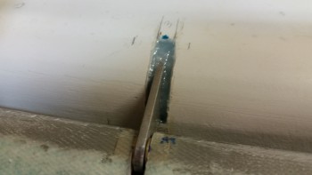
Floxing middle hingesFloxing middle hinges

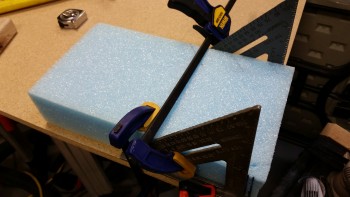
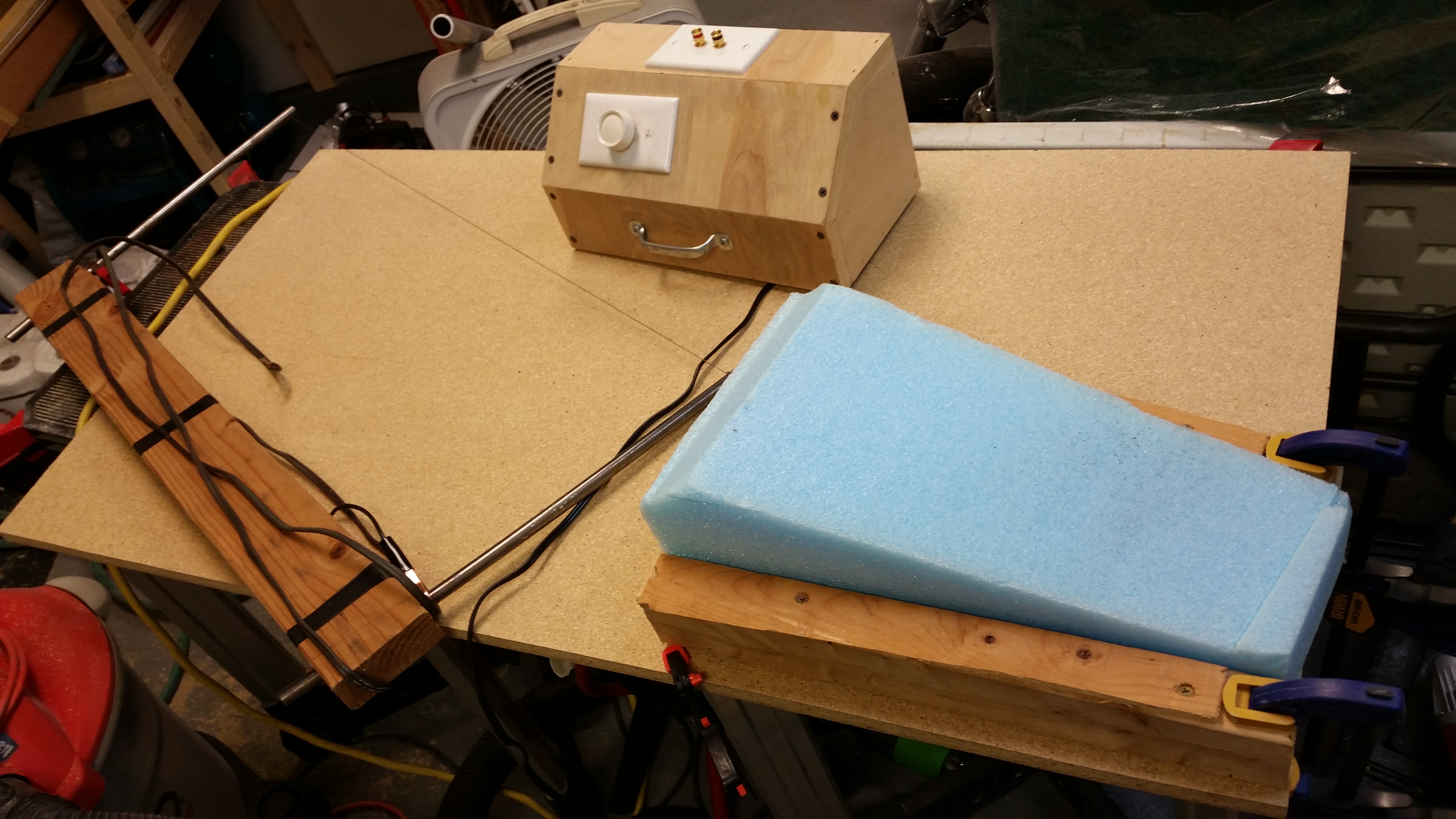
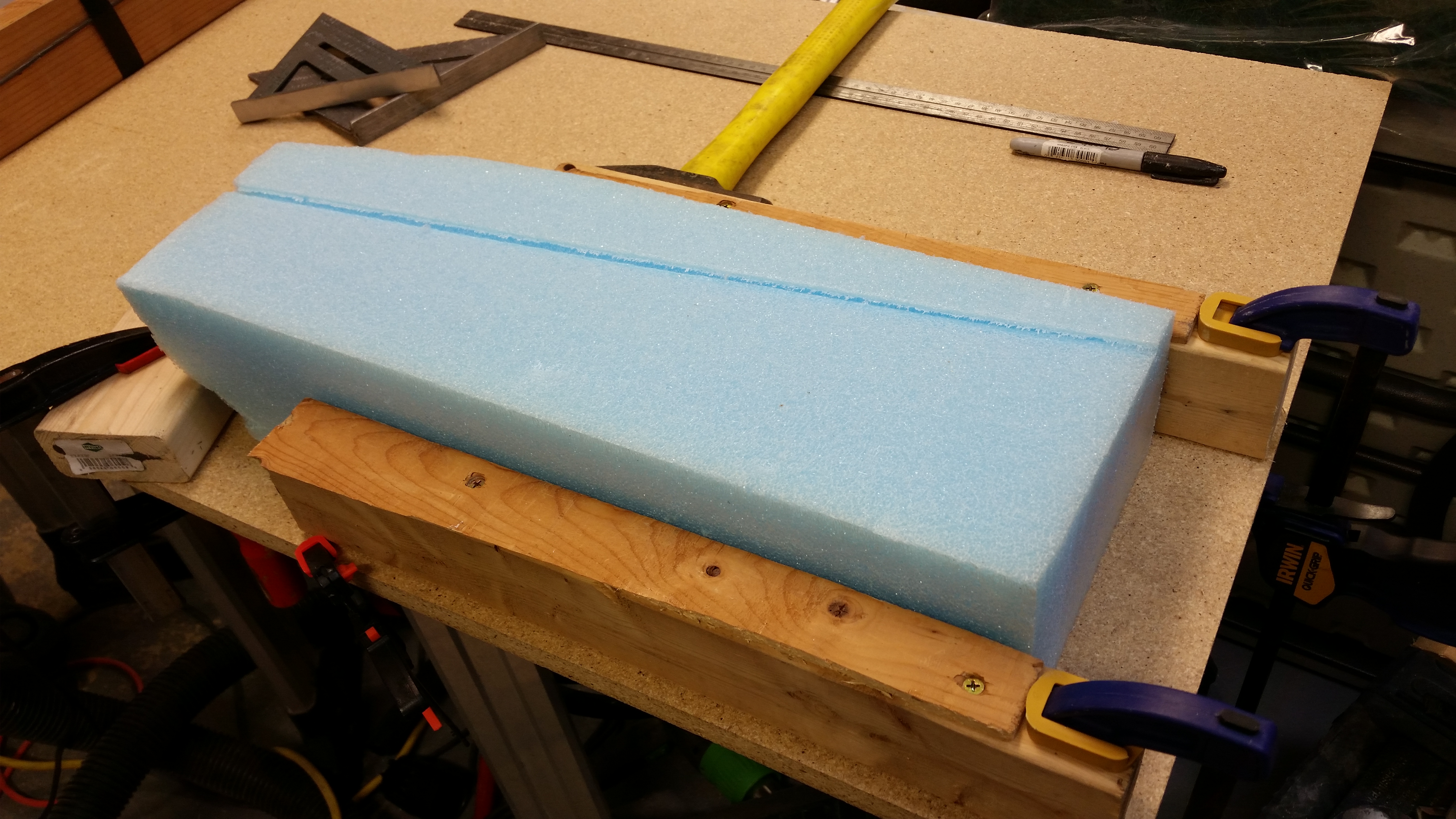
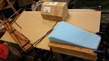
While the midpoint hinges’ flox cures I attempted to remain productive the rest of the evening by cutting the blue foam wedges for the Roncz canard swoosh tips.  I figured the easiest, cleanest way to cut the blue foam was using the hot wire cutter.

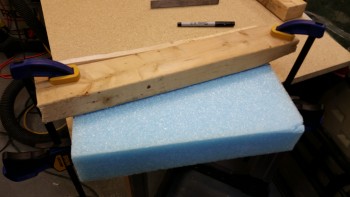
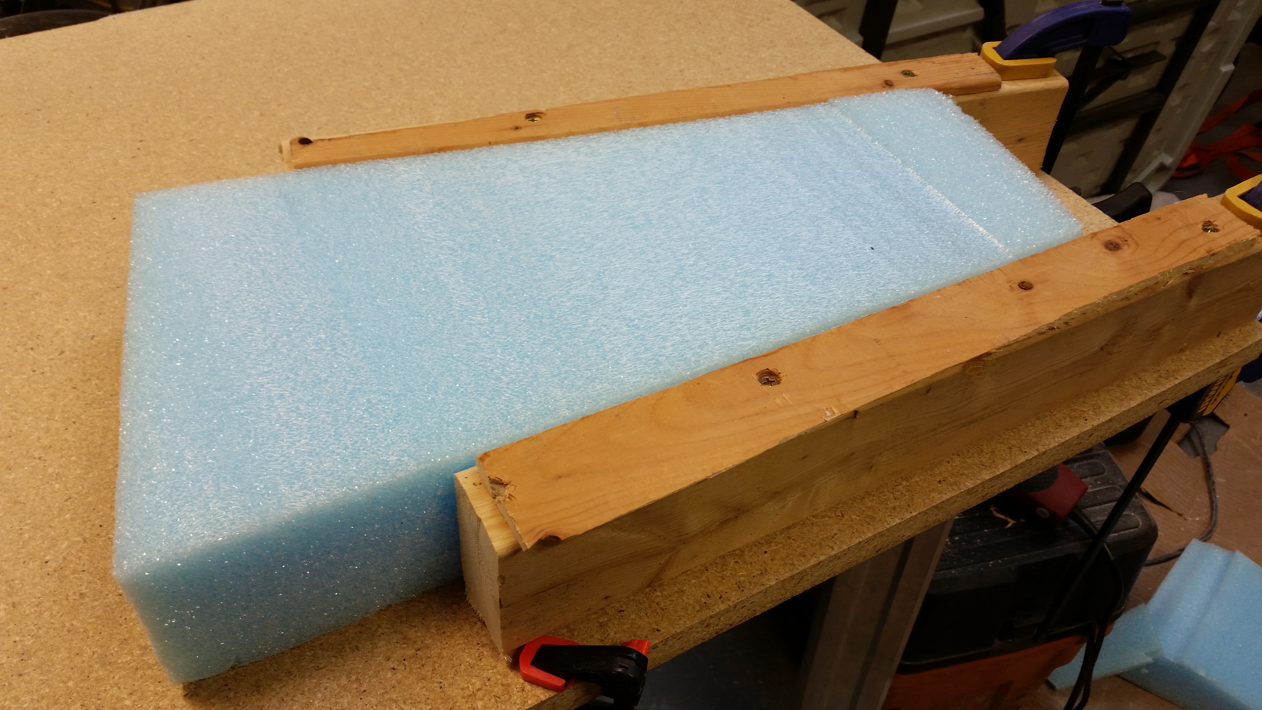
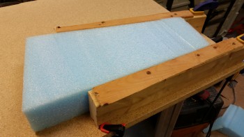
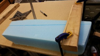
I added a 1/4″ scrap runner to the top of two 17″ long 2×3’s that I cut.  Of course the 2×3’s are, interestingly enough, 2-1/2″ wide.  I then clamped the 2×3’s on each side of the first piece of blue foam and tested it out.
Hot Wire cutting "swoosh" tips

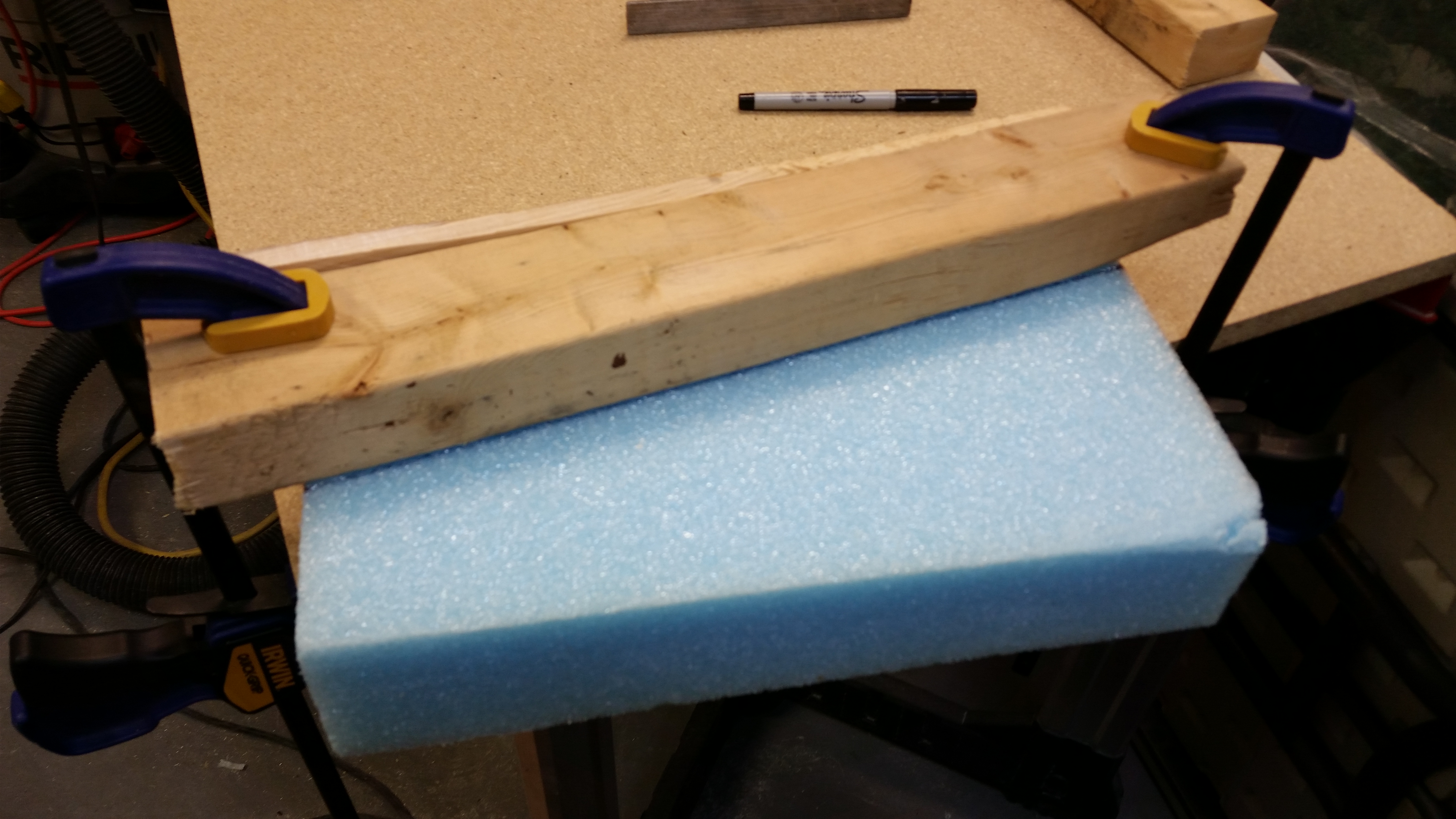
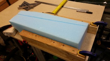
And here’s the result.  Not bad, but the hot wire cutter definitely felt “dull.”
Hot Wire cutting "swoosh" tips

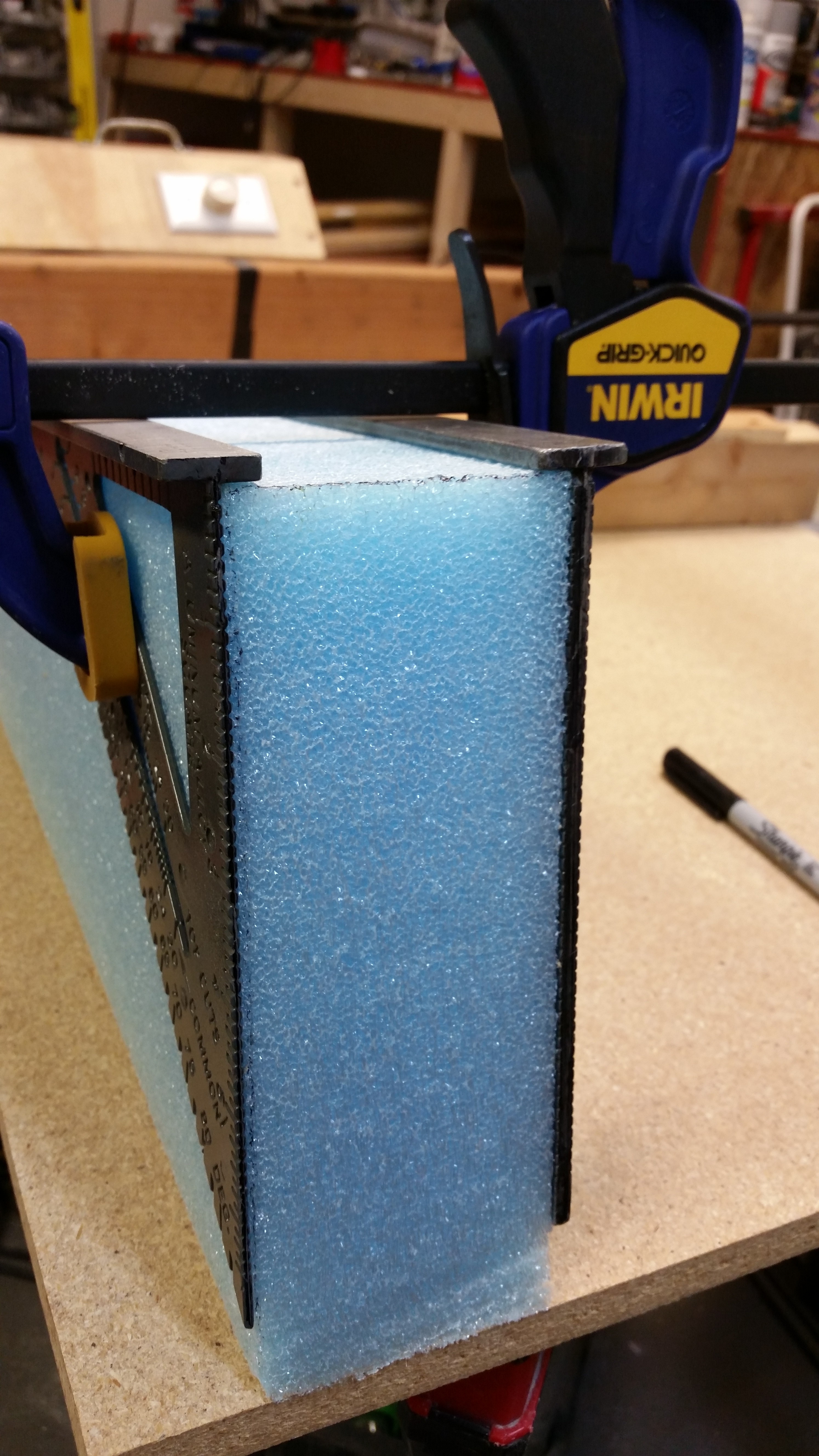
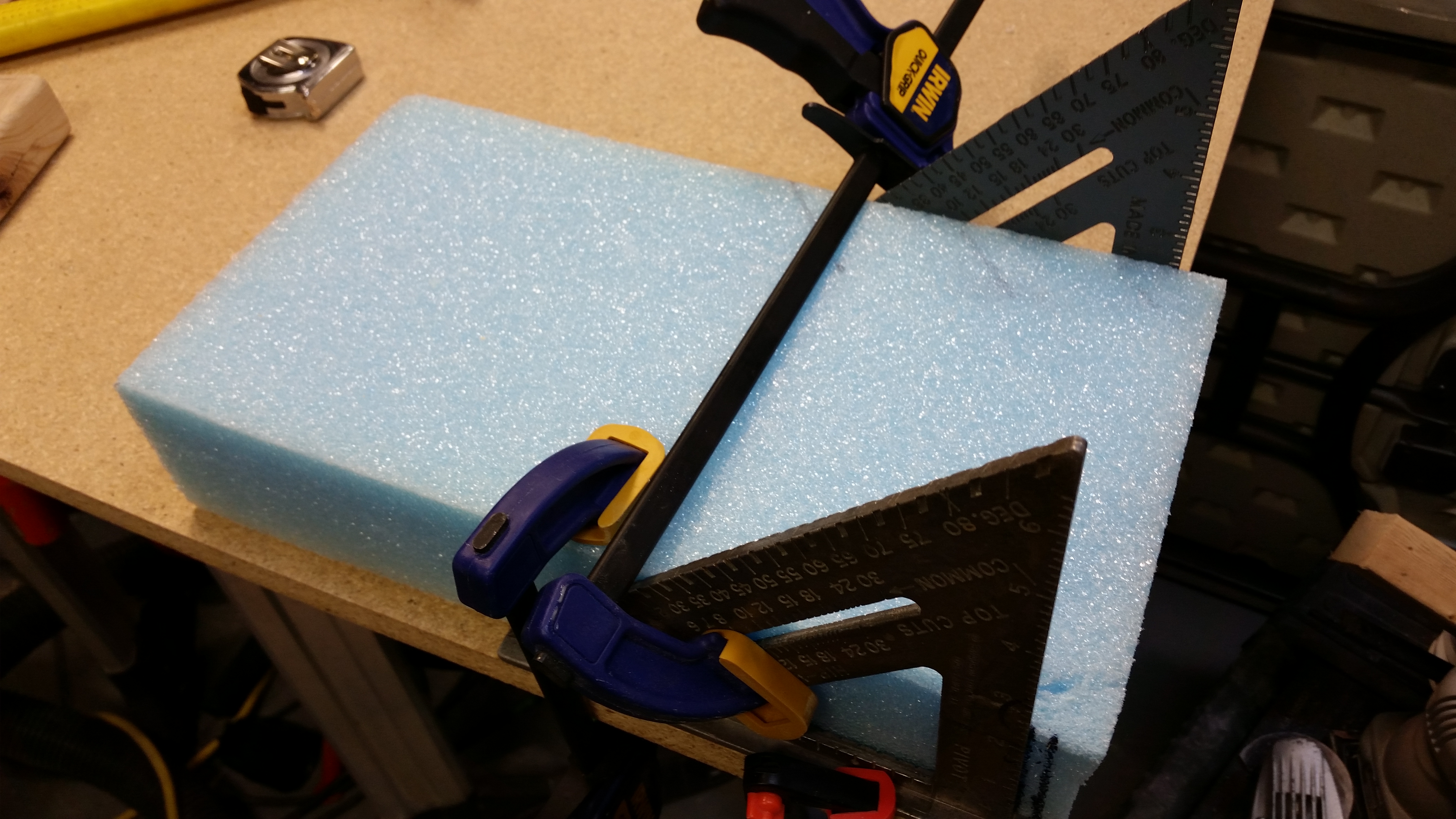
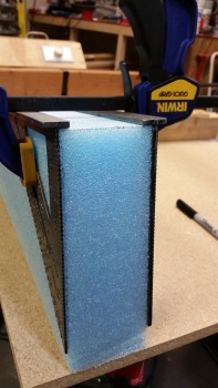
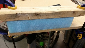
I continued cutting the first blue foam piece to get the swoosh tip piece as per the plans dimensions.
Hot Wire cutting "swoosh" tipsHot Wire cutting "swoosh" tips

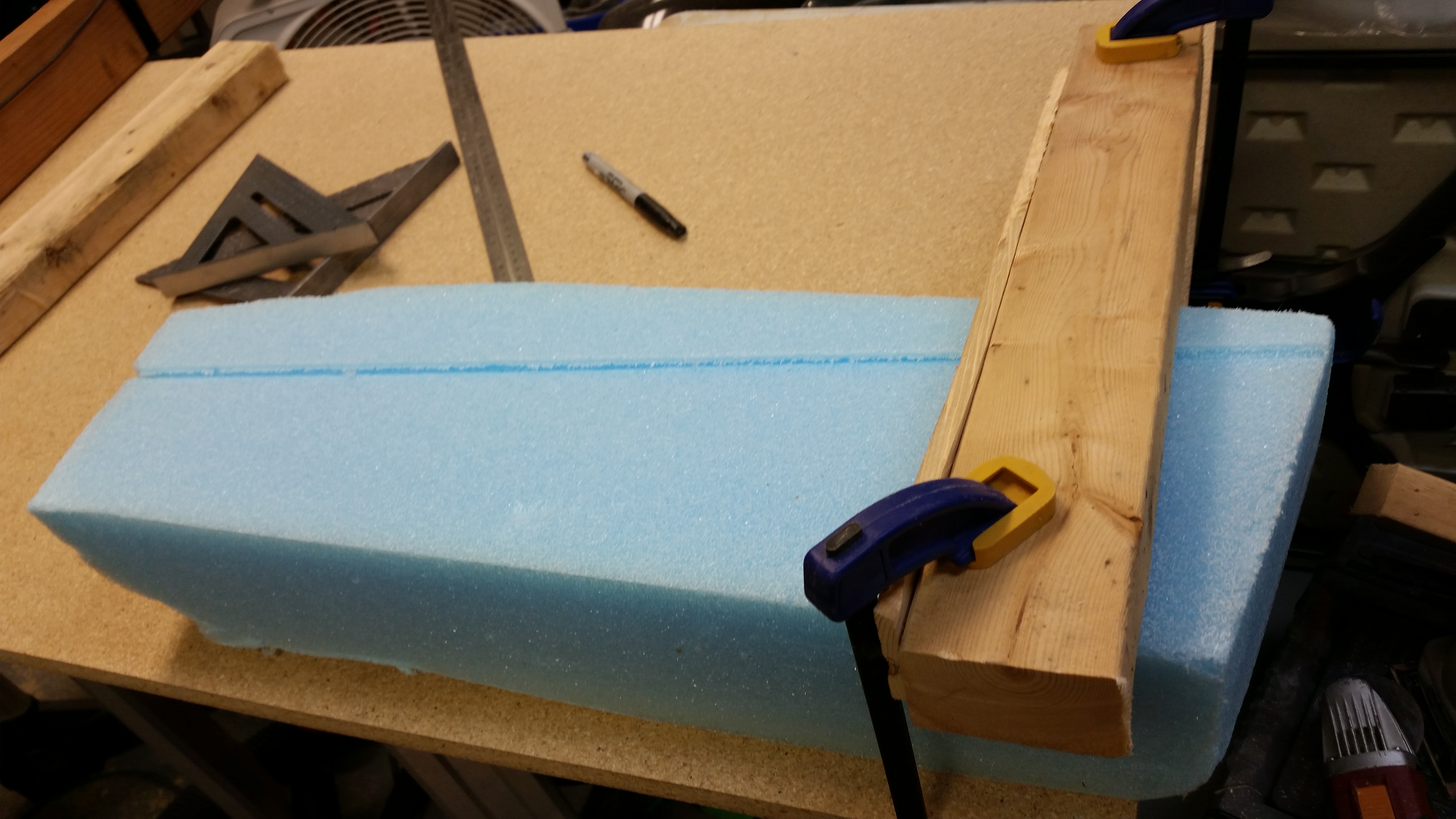
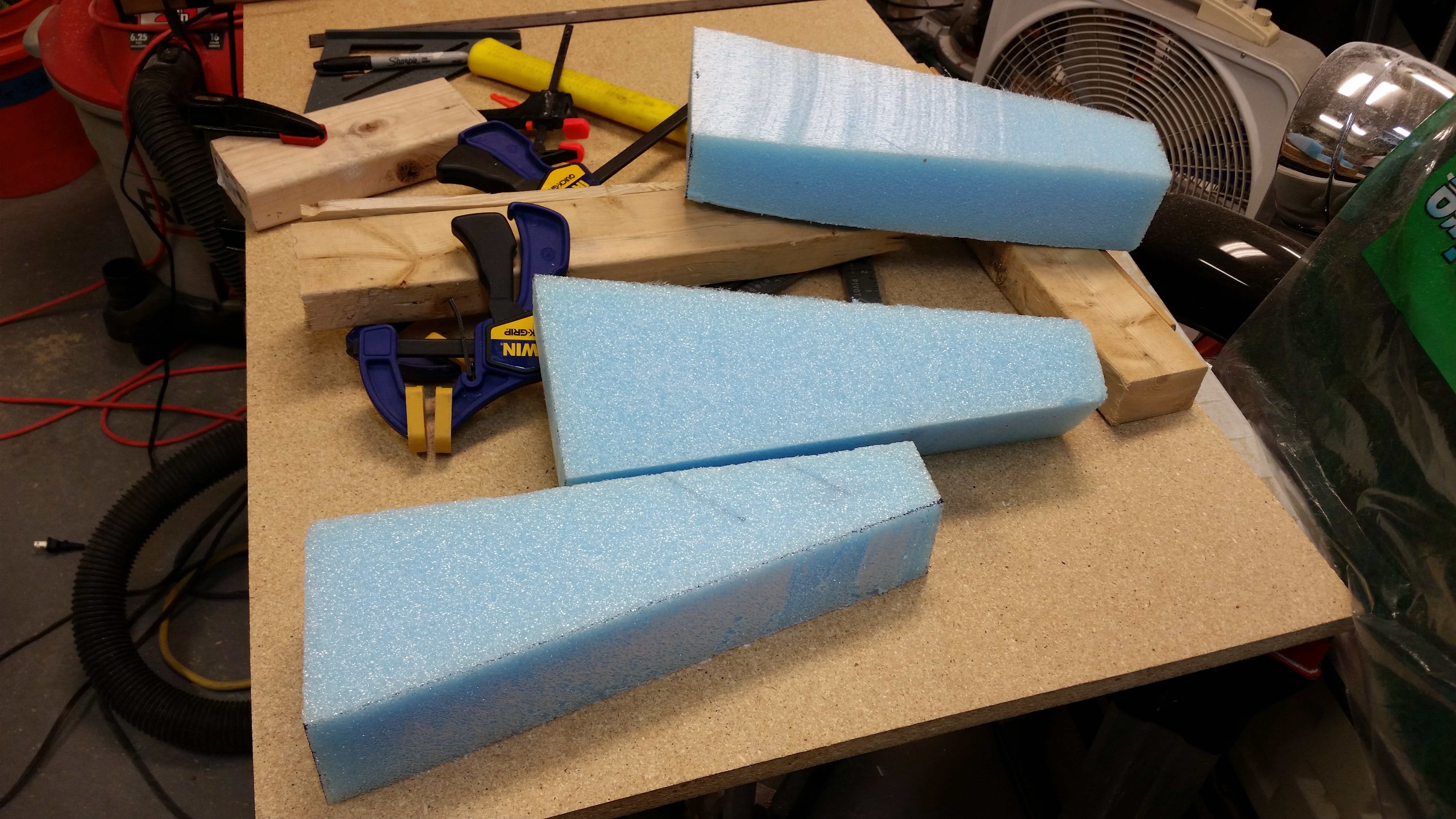
And then I grabbed another piece of foam to make the second blue foam canard swoosh tip wedge piece.
Hot Wire cutting "swoosh" tipsHot Wire cutting "swoosh" tipsHot Wire cutting "swoosh" tipsHot Wire cutting "swoosh" tips

Funny, but if I had started with the first piece of foam, I would have ended up with the two swoosh tips that I needed.  Oh well, now I have a spare!
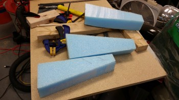
Roncz Canard "swoosh" tips

The next step will be to finalize the floxing in of the elevator hinges into the canard hinge slots.  Since I won’t mess with the elevators or canard for a full 24 hours after I set the hinges, I’ll be working on getting the top canard contour “E” template traced and made into a canard top contour sanding block just as I did for the bottom.  I’ll also find the pieces of UNI for the canard tips, locate and/or procure the plastic tubing for the canard tip elevator hinge pin bracket, etc.

Bottom line is that there is plenty of prep stuff to keep me busy while the elevator hinges flox cures.

 

Chapter 11 – Prepping elevators

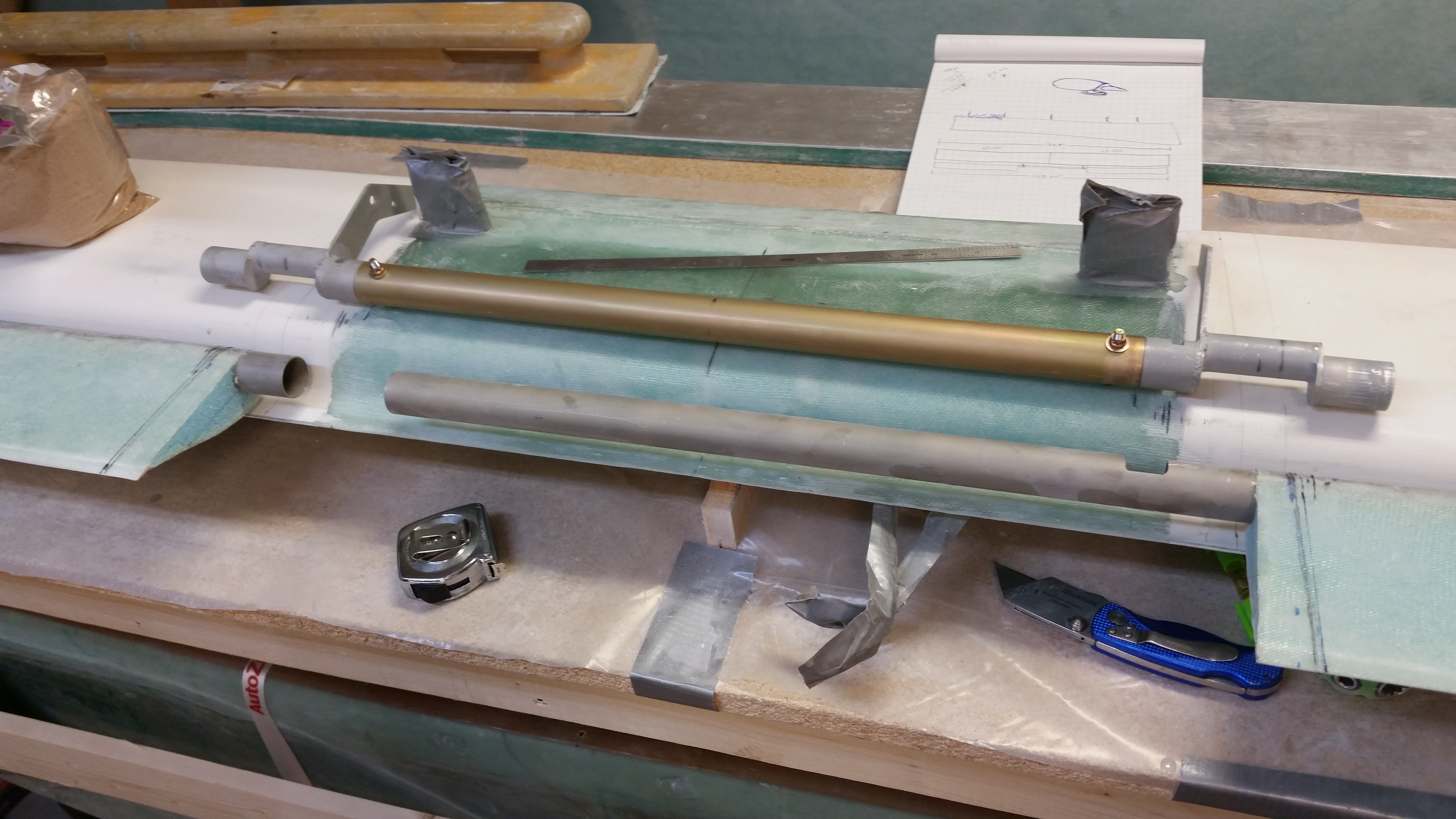
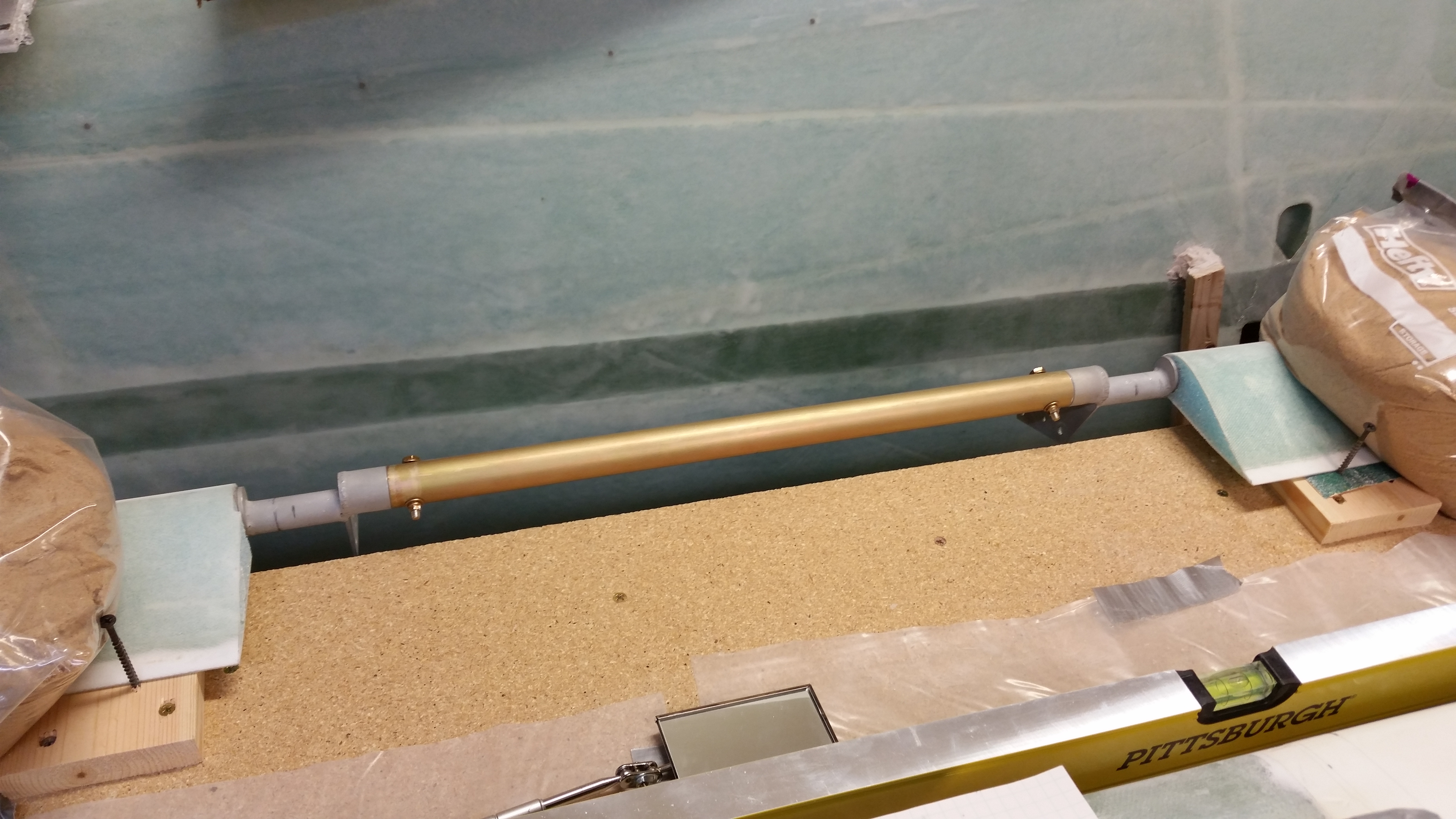
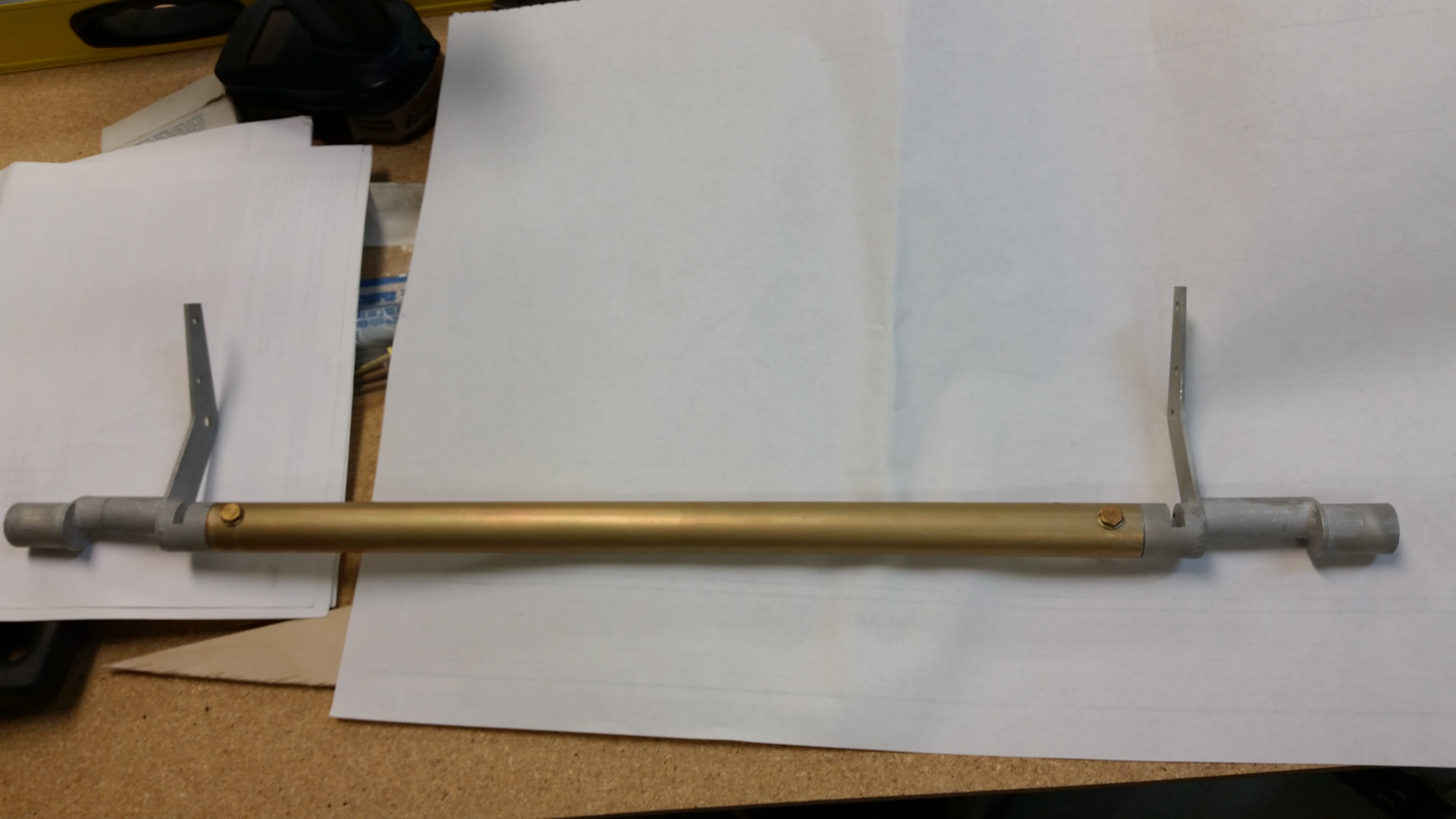
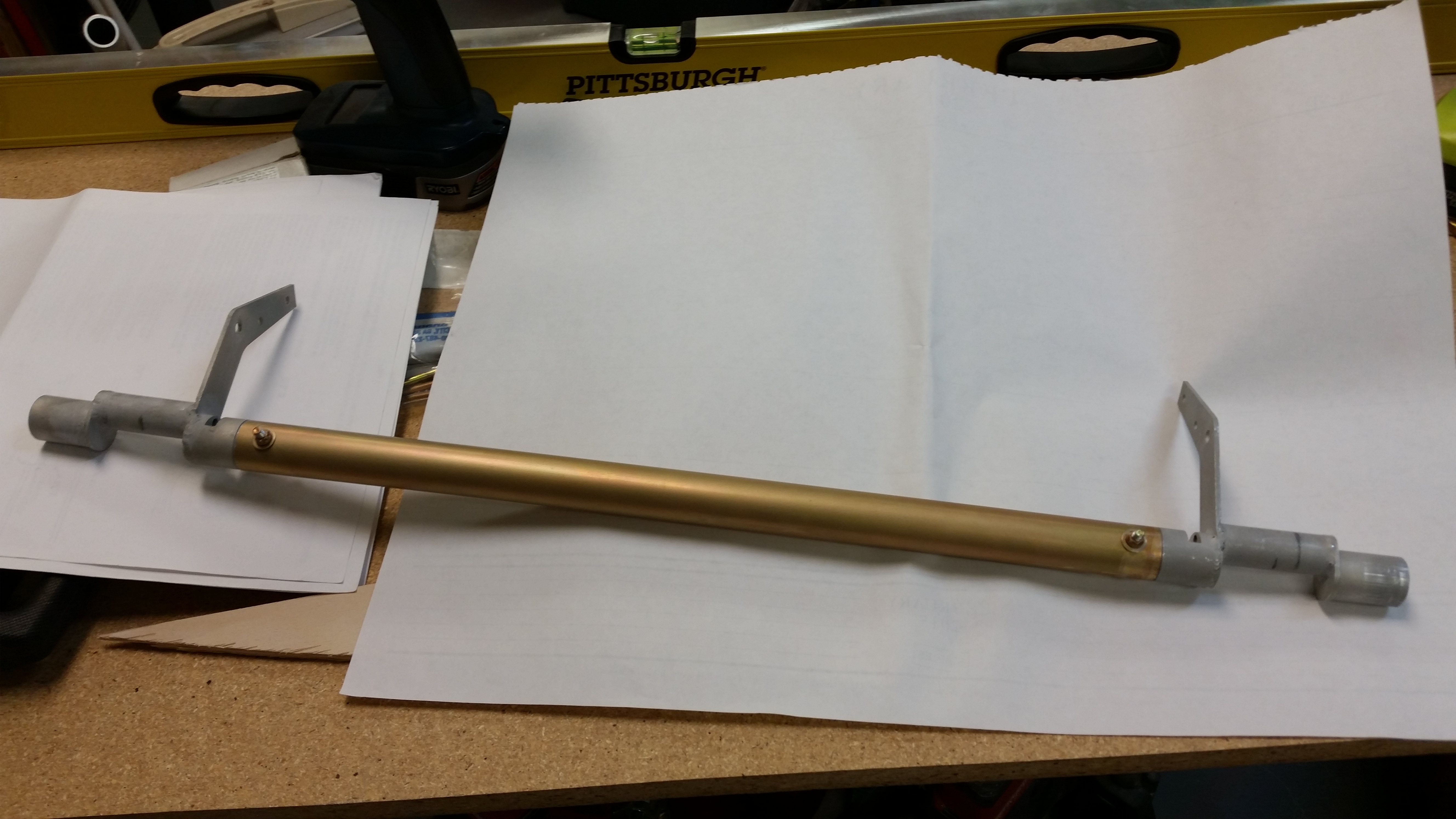
I started off today by nailing down the required length of the elevators in order to get the spool tube & offset assembly mounted to the elevators.  In the picture below, the torque offset at each end of the center spool tube assembly needs to be inserted into the inboard elevator tube, drilled and secured with an AN3 bolt on the respective elevators.

To get the two elevators and center spool tube assemble bolted together, I first needed to know what the required length for these individual pieces are when they’re attached as one.  Obviously if it’s all too long then it won’t fit inside the swoosh tip end caps (and the hinge & hinge hard points won’t align), and clearly being too short in length causes problems as well.

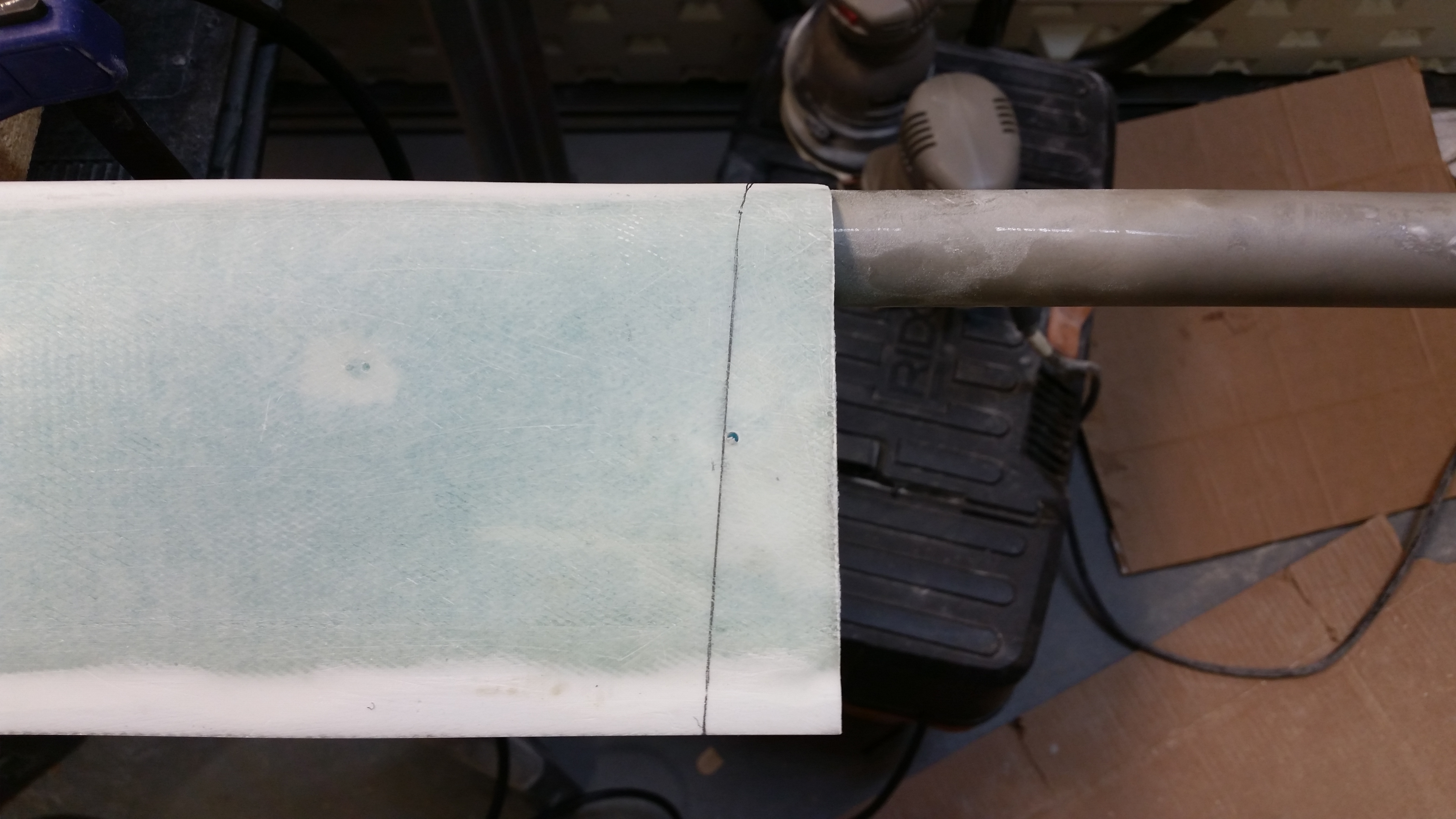
I needed to keep account of the 1/16″ minimum clearance between the outboard elevator edge and the not yet glassed swoosh tips.  The Cozy elevator plans say 0.1″ and I’ve also heard a 1/8″ gap bantered around as well.  I started with 1/16″ inch, but then using a popsicle stick ended up with about a .083″ gap (or around 5/64″ of an inch).  With the outboard elevator edges good, I moved inboard to figure out where I needed to cut the actual elevator, and its shape, and then where I would need to cut the actual elevator tube on each side to ensure all these dimensions would synch up.

Determining elevator lengths

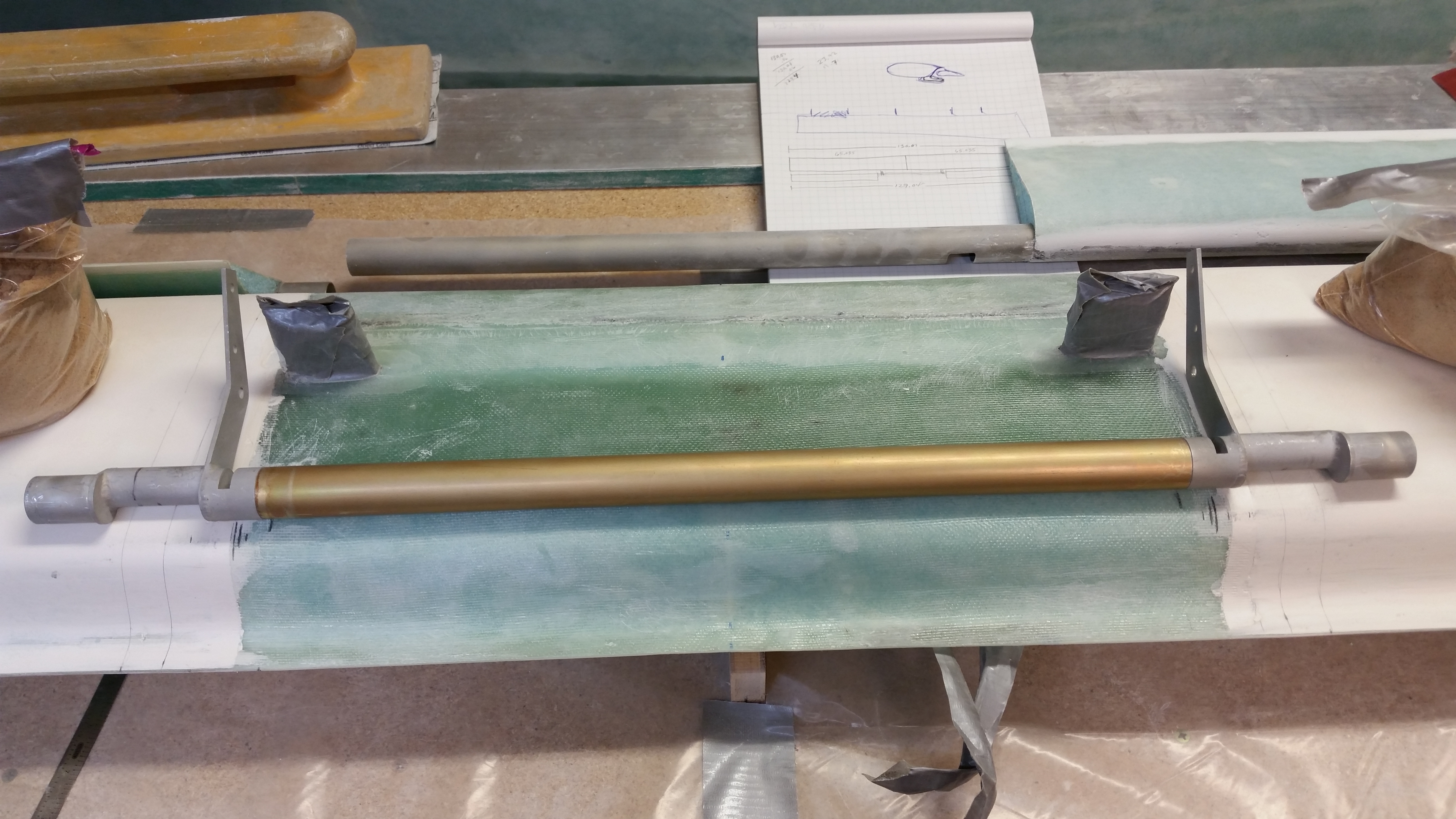
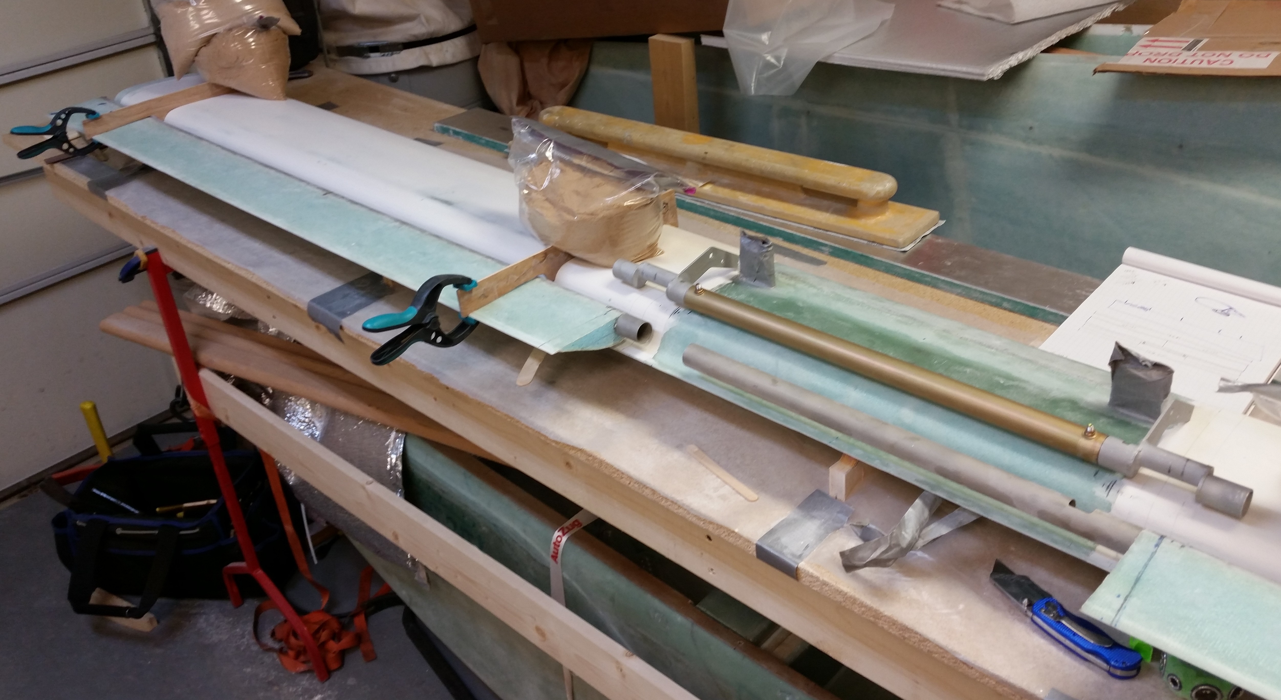
I’d like to point out, for those that may still be slightly confused as to what I’m doing here with this whole “Spool Tube Assembly” thing that the Long-EZ clearly doesn’t have per plans.  The pic above is perfect for showing the “old” Long-EZ way of installing the elevators, with the longer left elevator tube crossing the fuselage and then both torque offsets getting mounted together within an inch or so of each other on the right side of the fuselage.  Sitting atop the canard in the above pic is the “new” way, or simply installing torque offsets from the Cozy.  Since the Cozy has a control stick on the fuselage (cockpit) sidewall both left and right, then it stands to reason there’s a  torque offset on each side of the fuselage to connect to the control stick linkage.  The “spool tube” merely connects the two torque offsets, and thus the elevators, from one side to the other.  Again, to explain WHY I’m dong this, I’ll quote the part description from the CG Products web site (In short, it turns the banana-shaped hole into a small round hole so you don’t freeze your tootsies off in flight!):

While not a “per plans” part in the Long-EZ, these parts solve the serious draft problem in the Long-EZ where the eccentric moving elevator torque tubes come through the fuselage walls. This is accomplished by shifting a portion of the mechanism to be concentric with the hinge axis.


Once I got the outboard elevator ends figured out, I installed the hinges and marked the locations of the hinge slots on the canard on both sides.
Marking up elevator hinge slots

Marking up elevator hinge slots

I then removed the elevator, removed the hinges so as not to cut the 3/16″ stainless steel hinge pin by accident.  I transposed the marking on the bottom of the elevator to the top, and checked the accuracy of my marks by drilling a 1/16″ hole straight through the elevator from the bottom to the top . . . right on the line each side!

Trimming inboard elevator

I then used the Fein saw to cut through the elevator skin & foam.

Trimming inboard elevatorTrimming inboard elevatorTrimming inboard elevator

Here’s the final product:

Inboard elevator trimmed

Trimming inboard elevatorTrimming inboard elevatorDetermining elevator tube cutoff point

After trimming the inboard elevator on the other side, I marked up the actual aluminum tube to be trimmed down.

Determining elevator tube cutoff point

Determining elevator tube cutoff point

I ended up cutting one elevator tube with the chop saw, and the other side–in trying to conserve more of the elevator’s inboard edge shape–with the Dremel tool, then sanded it to length.

Here are the elevators, each cut to length, mocked up & temporarily attached to center spool tube assembly.  I double checked all the lengths & dimensions, and it all looked good.

Elevator tubes cut to length

A long view . . .

Elevator tubes cut to length

I then hunted around for a decent sized board–moreover, one that was straight!– to cut for the jig mounting bases for the elevators to sit on while they are bolted to the torque offsets on the end of the center spool tube.  I cut a pine board I had into 6″ lengths and then screwed them to the work bench, all with a 1″ overhang.

L&R elevator & spool tube connect jigs

I then checked the entire length for straight & level with my German aluminum straight board.  My second and third jig was a little low, so after hunting around a bit for something to fill the gap, I got the idea to recycle a piece of 80-grit PSA sandpaper (sticky backed) to use on the second jig, and on the third jig a piece of 36 grit.  Those did the trick and the mounting jigs were all straight and level!

L&R elevator & spool tube connect jigs

I then mounted the elevators to the center spool tube assembly & torque offsets.  Since there is a hinge that goes into each torque offset assembly, then the 3/16″ stainless steel hinge pin goes all the way into the torque offset.  This really makes it easy to figure out the angle of torque offset arms because the hinge pin must be installed.  In other words, if I’m off, it won’t be by much at all!

L&R elevator & spool tube connect

I marked up a popsicle stick with a line at 1.6″ to set the distance between the back edge of each jig to the TE of the elevators.  As I measured each TE gap on the jigs, I weighed down the elevator at that jig.  I then installed the 3/16″ stainless steel hinge pin into each side [NOTE: If I had been thinking more proactively, at this point I would have installed the hinges to avoid having to install them later and thus keep from having to manipulate the entire assembly as one complete unit].

L&R elevator & spool tube mounting

L&R elevator & spool tube mounting

Pardon the fuzzy pic below, but if you look closely at the root of each elevator you’ll see that  I’ve drilled the #12 hole on each side.

Holes drilled

Here’s a shot of each side of both the inboard foam edge of the elevator, and the screw I placed right behind the trailing edge of each elevator to keep the elevator from shifting away from the drill bit as I drilled the holes.
Screw to secure during drilling

Screw to secure during drilling

And here’s pretty much the same views only this time the bolt holding the elevator to the torque tube end is visible inside the foam.

Elevator bolt installedElevator bolt installed

The next step was to get the elevator hinge slots marked up for cutting.

Elevator hinge slots marked up

I then cut the slots for the hinges and dug out the foam down to the top side glass.
Elevator hinge slots

Elevator hinge slots

After vacuuming out the hinge slots in the foam hard points embedded inside the canard, I pulled off the sandbags.
Single elevator unit

I then installed all 6 hinges with their associated washers.

Elevator hinges installed

Elevator hinges installed

I then reset the “L” brackets, secured them in place with sandbags, and remounted the elevator-spool tube-torque tube assembly to the canard.  I slid the hinges into the hinge slots to check their fit, which will definitely need some tweaking.

Mocking up elevator unit & hingesMocking up elevator unit & hingesNext I’ll be working–probably all day long–to get the elevators situated correctly on the canard and then the hinges floxed into place inside the hinge slots.


Chapter 11 – Elevator Mounting

After attending a work meeting this morning, I started out today by spending a couple of hours finalizing my plan for installing the elevators on the canard after reviewing the Long-EZ plans, the Roncz canard plans, the Cozy elevator install plans, and my notes.

The first task I needed to complete was to mount the two CZNC-12A Torque Tube Offsets to the each end of the Spool Tube.  Of course, to do this I had to know exactly how long the Spool Tube needed to be.  I spent a good hour and a half mocking up the Torque Tube Offsets, the Spool Tube, and canard dimensions.  I really needed to lock down the dimensions of the fuselage in the F22 & F28 area to ensure that the elevators are mounted correctly.

After essentially transcribing the outline of the fuselage onto the canard surface, I checked and double checked the dimensions a few times over.  After confirming the numbers, I came up with a spool tube width of 17.6″.  This is 0.9″ less than I had originally estimated when I worked up the numbers in Germany back in 2013.

Before I started cutting anything I checked a couple more details in the plans & online.  I also gave Chrissi from the Cozy Girrrls a call to verify some of my install steps.  After chatting with Chrissi for about an hour on the elevators install (and a few other things), I was ready to pull the trigger.

I measured the spool tube & marked it with a piece of paper to ensure I would have a square cut (pic below).  I then cut the spool tube on the chop saw just a hair off the line (middle pic).   I then removed the paper and cleaned up the cut with sandpaper (bottom pic).

Spool tube marked for cutting

Spool tube cut to length

Spool tube ready for install

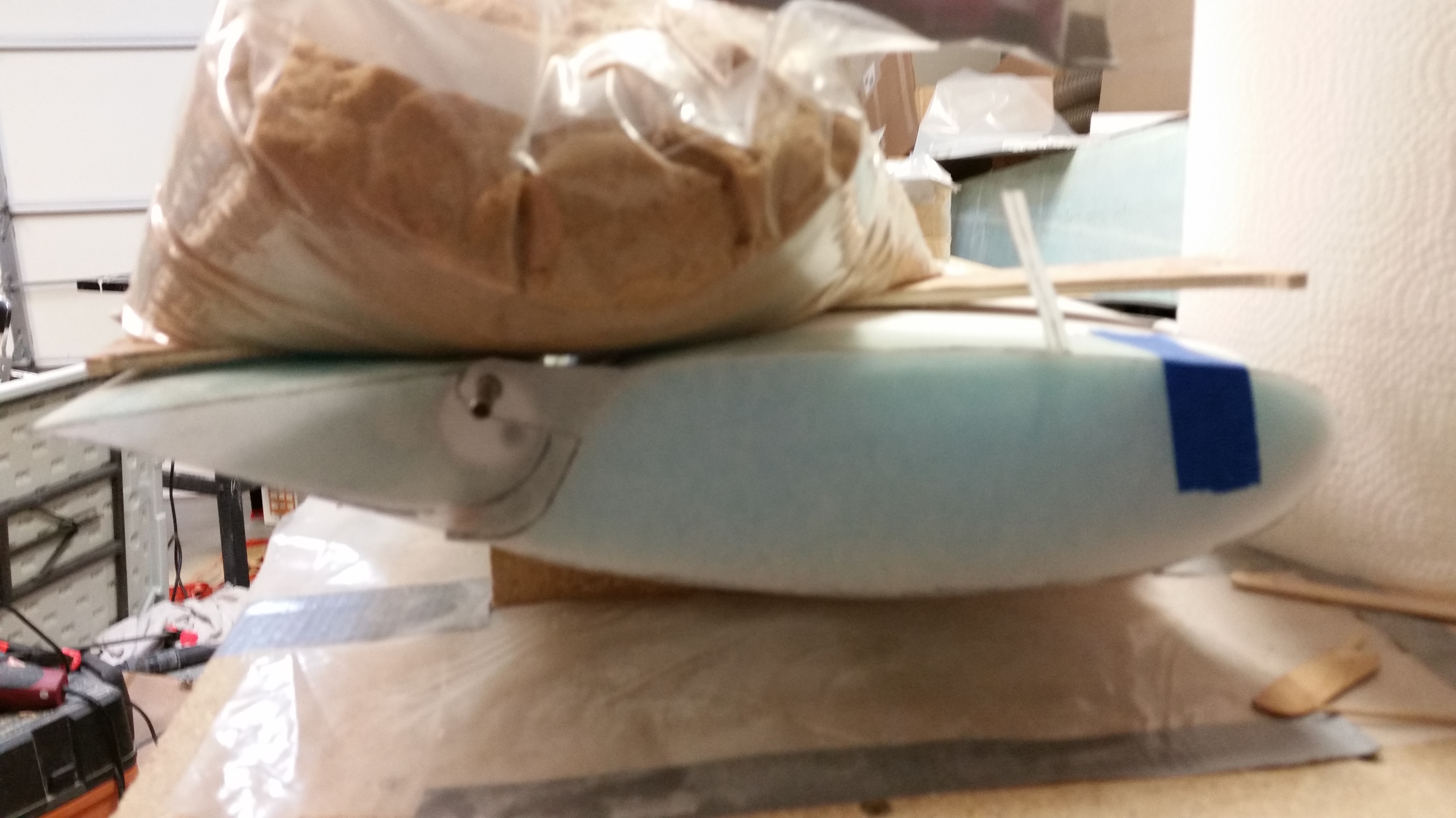
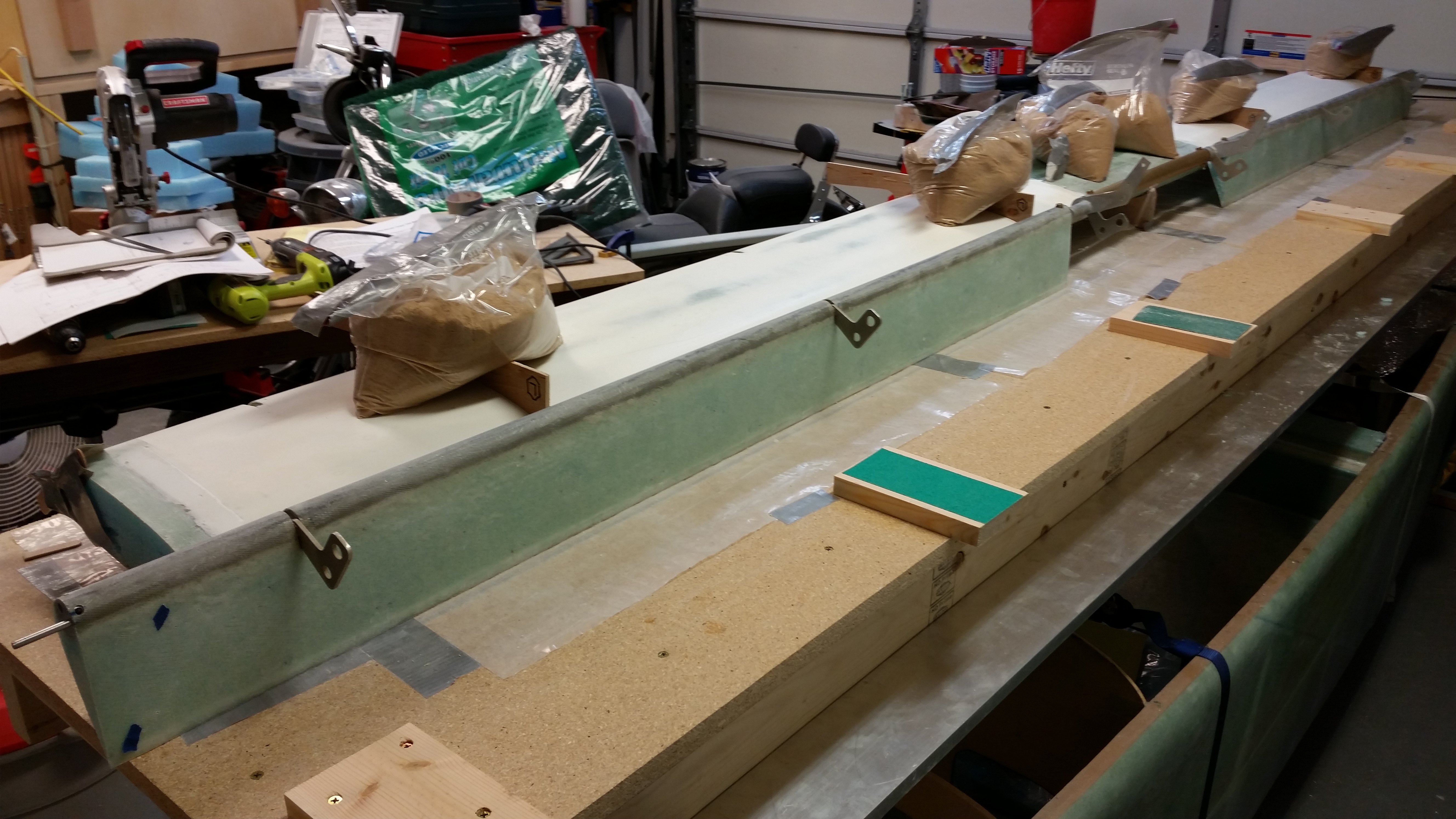
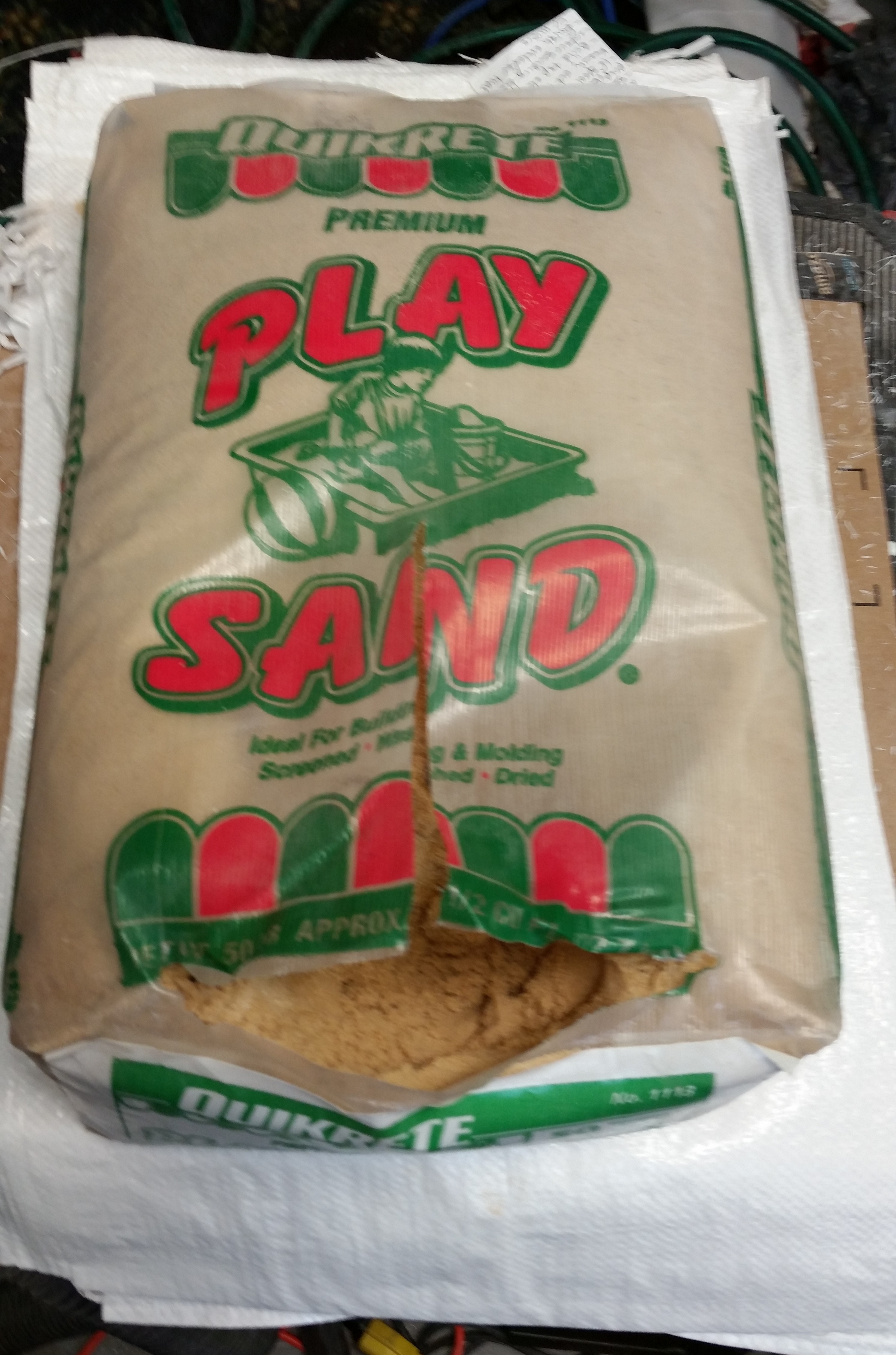
Now, in real time I showed the pics above out of order.  To cut the spool tube I needed to get the 50-pound bag of play sand off my cutting table.  So, I simply made up six 5-pound sandbags.  I took the leftover sand and dumped it into one of the sandbags I bought along with the bag of sand (the sandbags are the white plastic bags under the sand).

Sand for sand bags

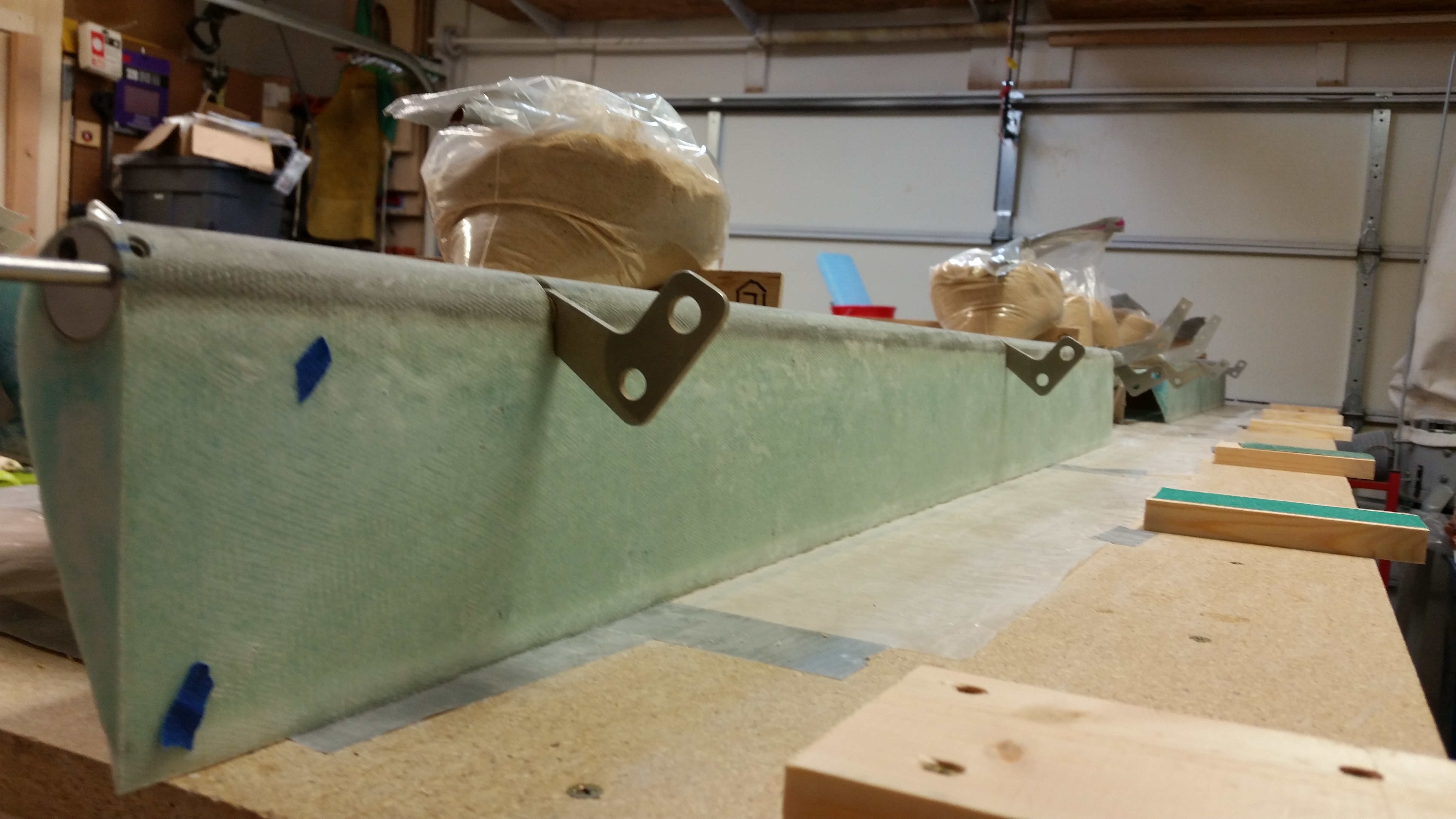
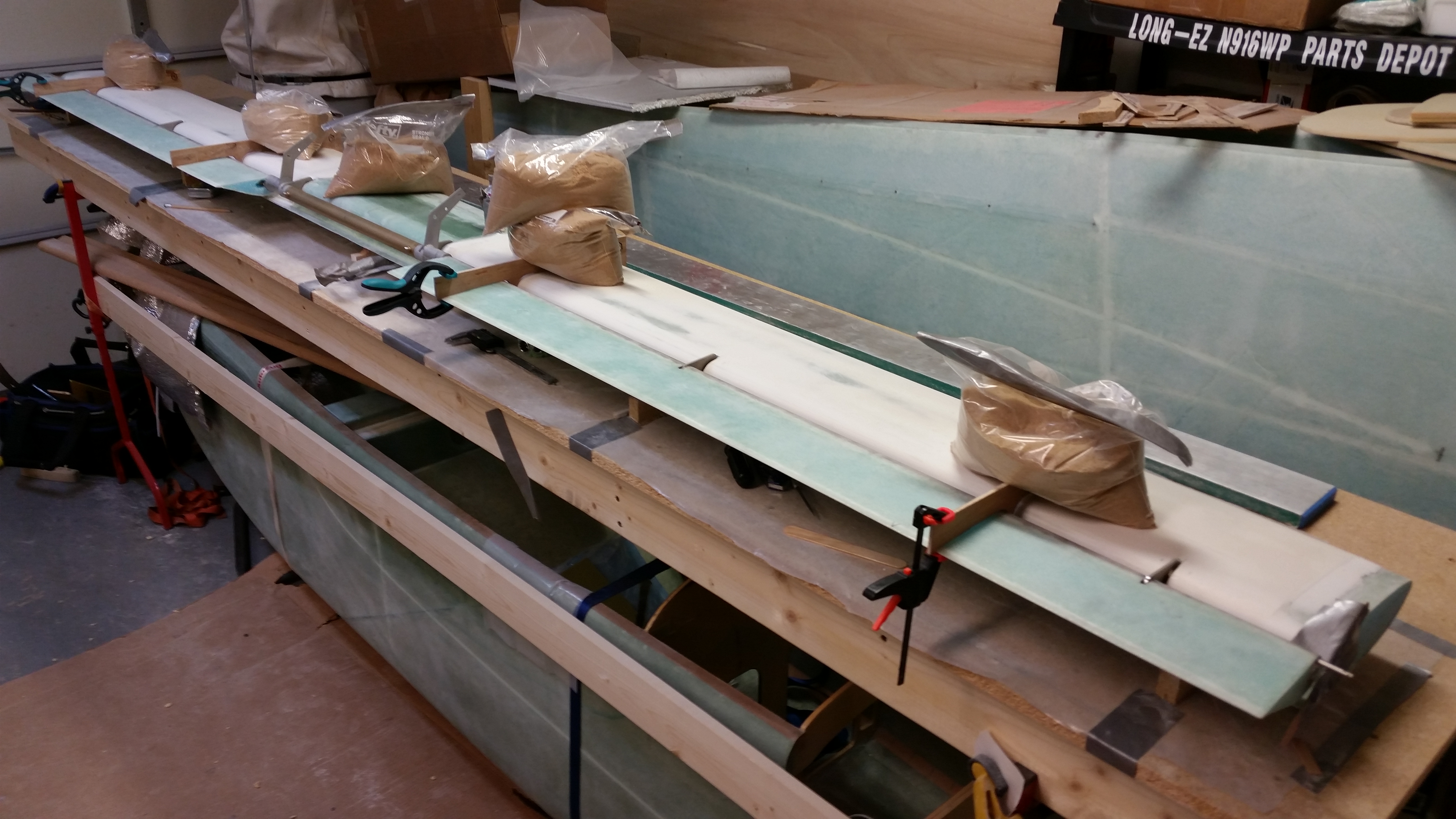
The sandbags I made are shown below placed over each “L” template.

Sandbags in place on "L" templates

Back on the spool tube: I mocked it up with the torque tube offsets in place & ensured it matched the marks I made up earlier (it did).

Spool tube mocked up with bell horns

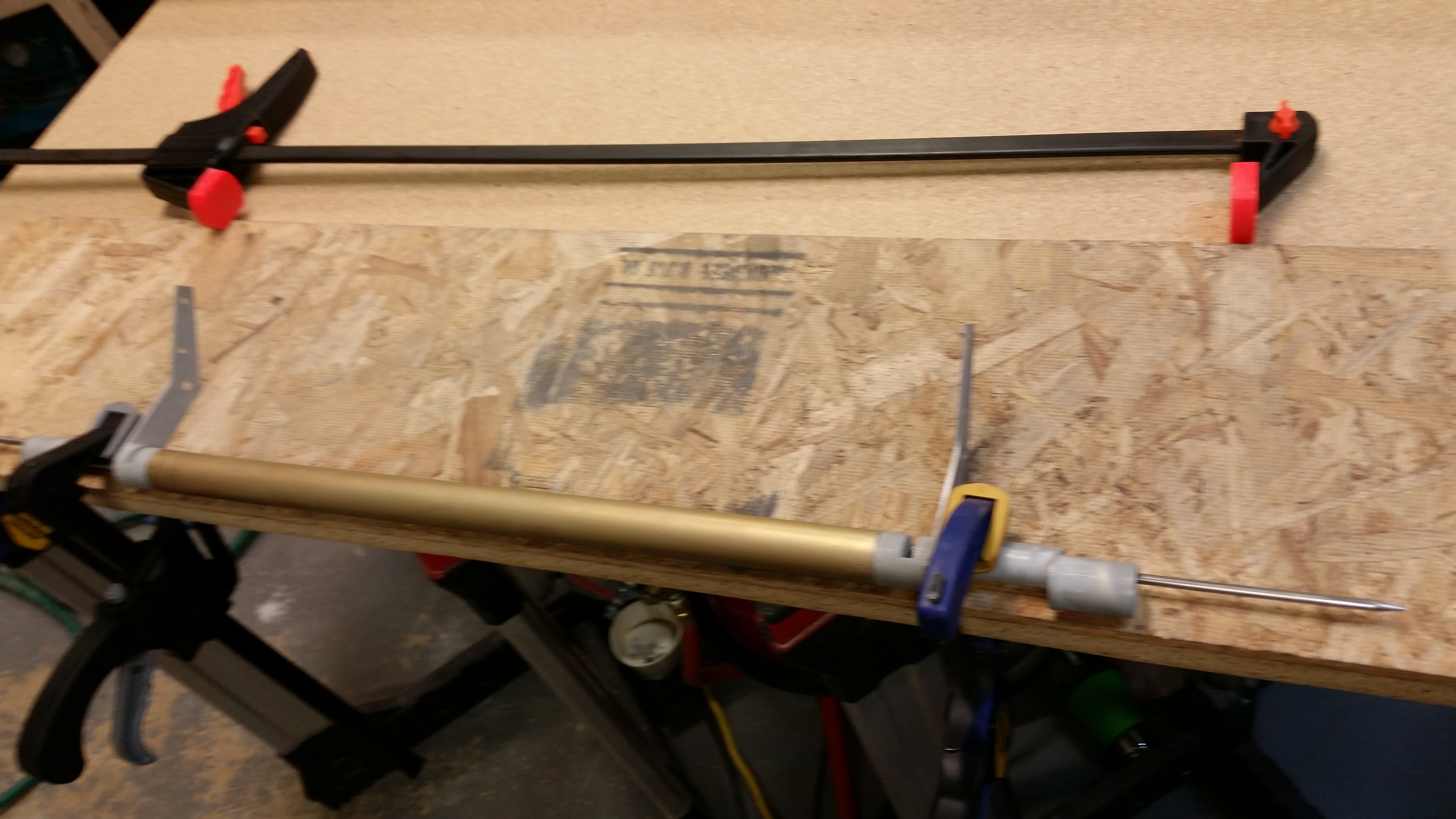
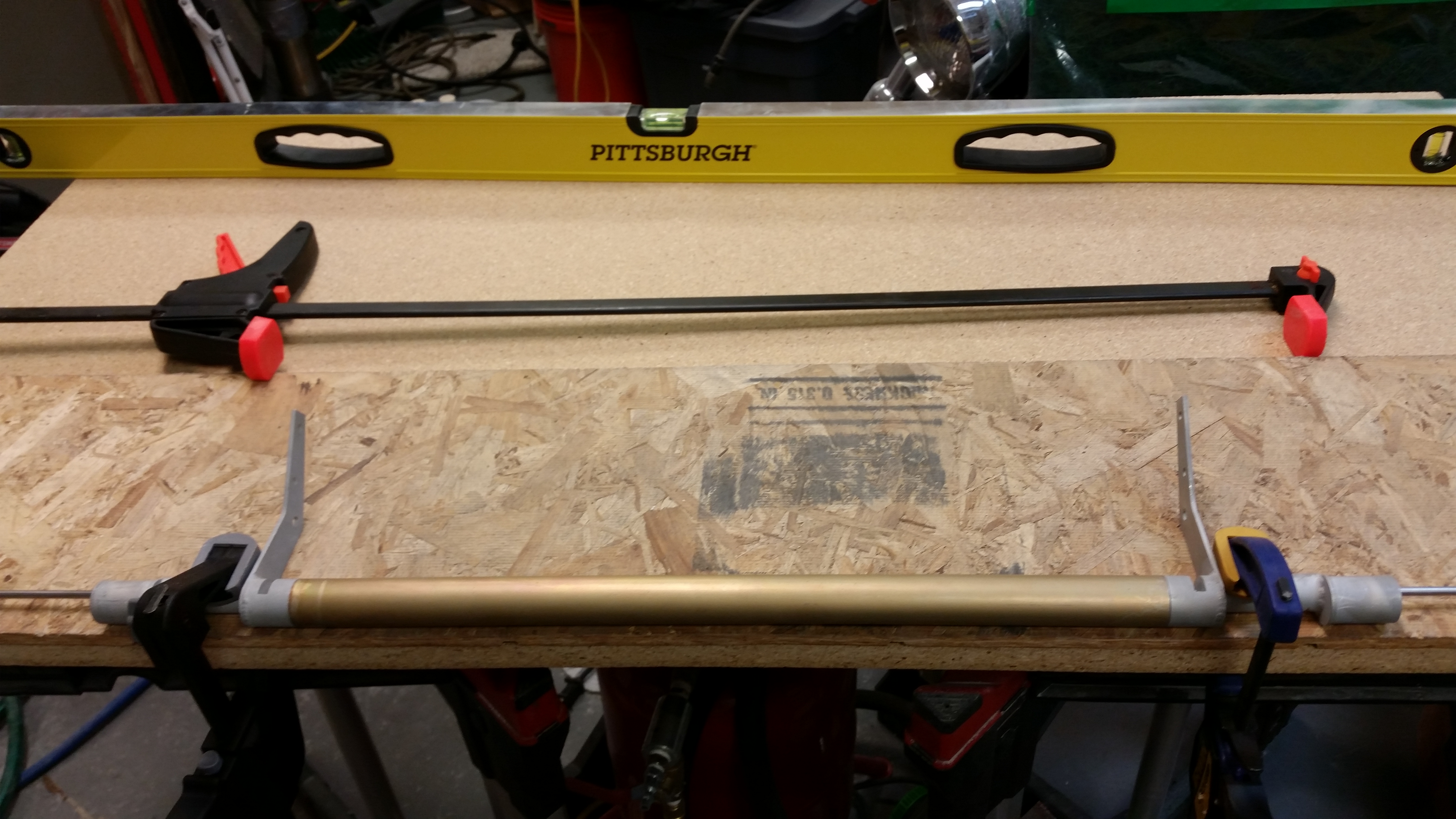
I set up a table to mount the torque tube actuators to the spool tube.  I clamped the whole assembly down to the table after ensuring it was all aligned.  To help ensure that all the pieces stayed aligned, I installed the 3/16″ stainless steel hinge pin all the way through from one end to the other.

Spool tube ready for bell horns install

Spool tube ready for bell horns install

Spool tube ready for bell horns install

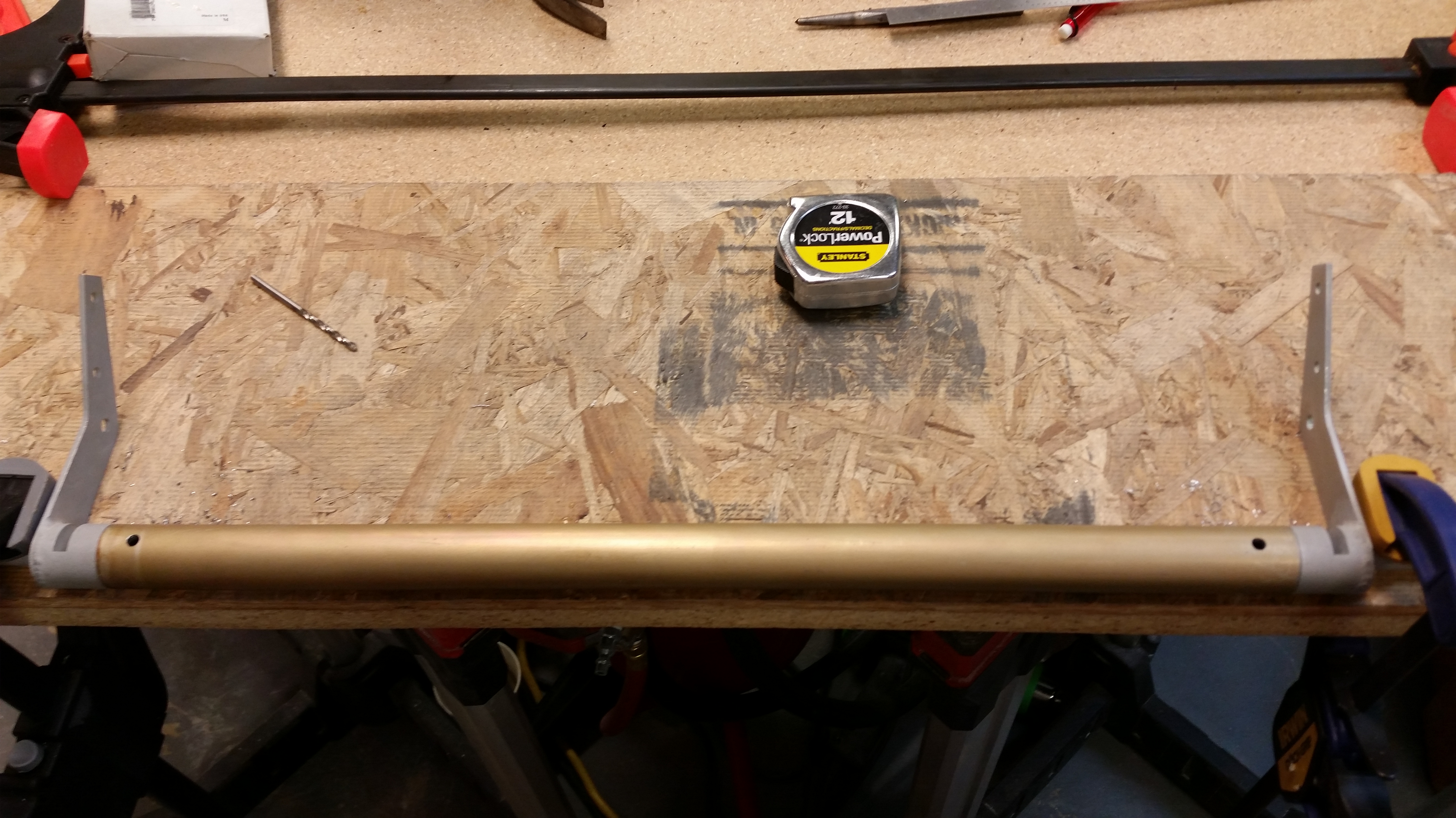
Below are a couple of shots after I drilled the two holes for the AN3 mounting bolts.

Bolt holes drilled

Bolt holes drilled

And here’s a couple of shots with the bolts installed (after I deburred all the holes) and the torque tube offsets mounted to the spool tube.

Spool tube & bell horns bolts installed

Spool tube & bell horns bolts installed

I then spent about another hour making the 0.2″ (actually 0.23″) gap spacers and mocking up the elevators.  Here’s a shot of the Left elevator with 3 gap spacers installed.

Elevator mount mock up

And here’s a couple of shots of the elevators loosely mocked up into place.

Elevator mount mock up

Elevator mount mock up

Tomorrow I’ll work on tweaking the elevators into their final positions, get the inboard ends of the elevators cut to length and mounted to the torque tube offsets.  I’ll also be installing the stainless steel hinge pins and hinge tabs to allow for marking the hinge locations on the canard.  In addition, I plan to cut the 6 slots for the hinge tabs into the bottom surface of the canard.  Finally, if all goes according to plan, I’ll be floxing the hinge tabs into place.


Chapters 10/11/25 – Primer on, Primer off!

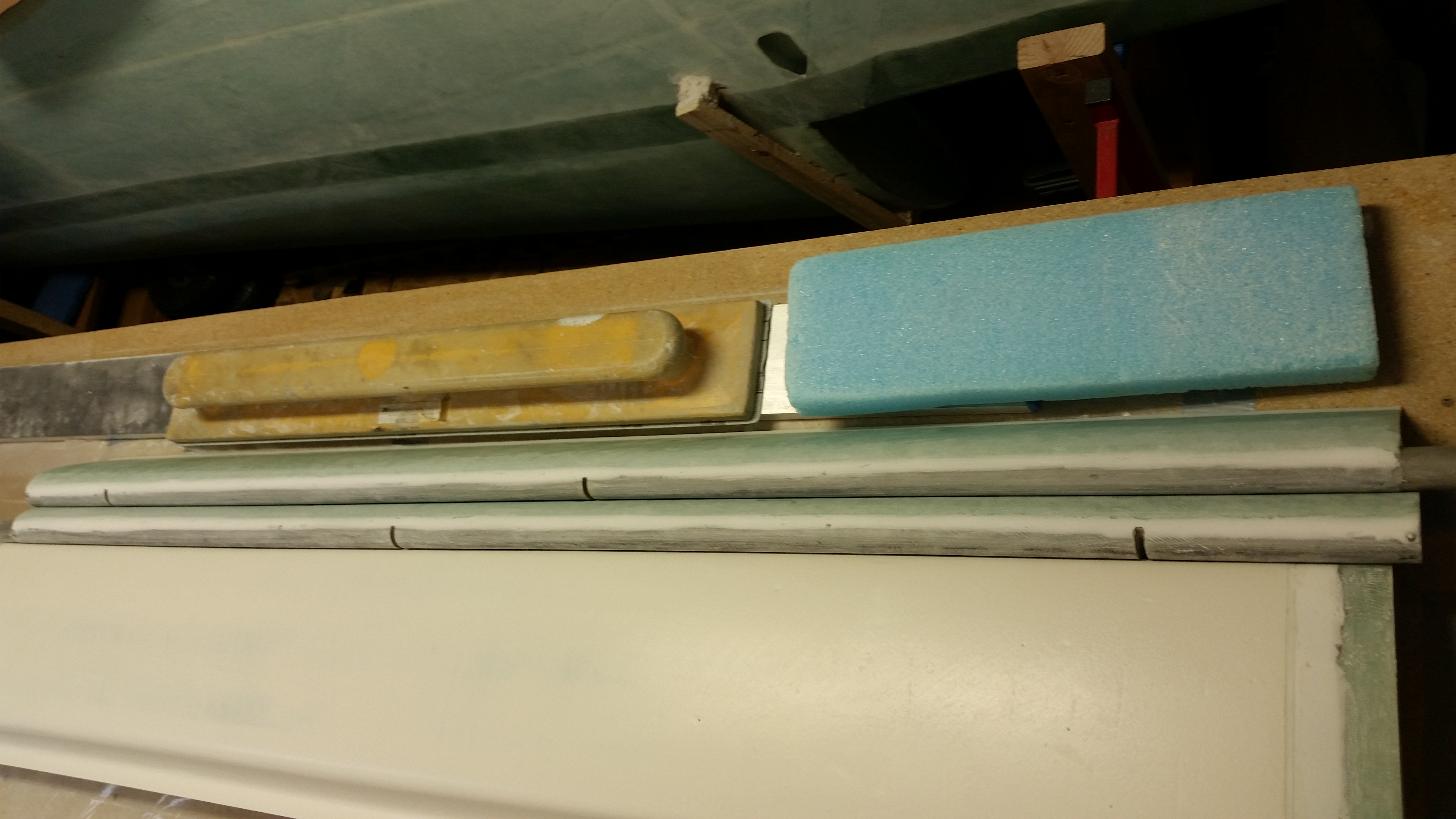
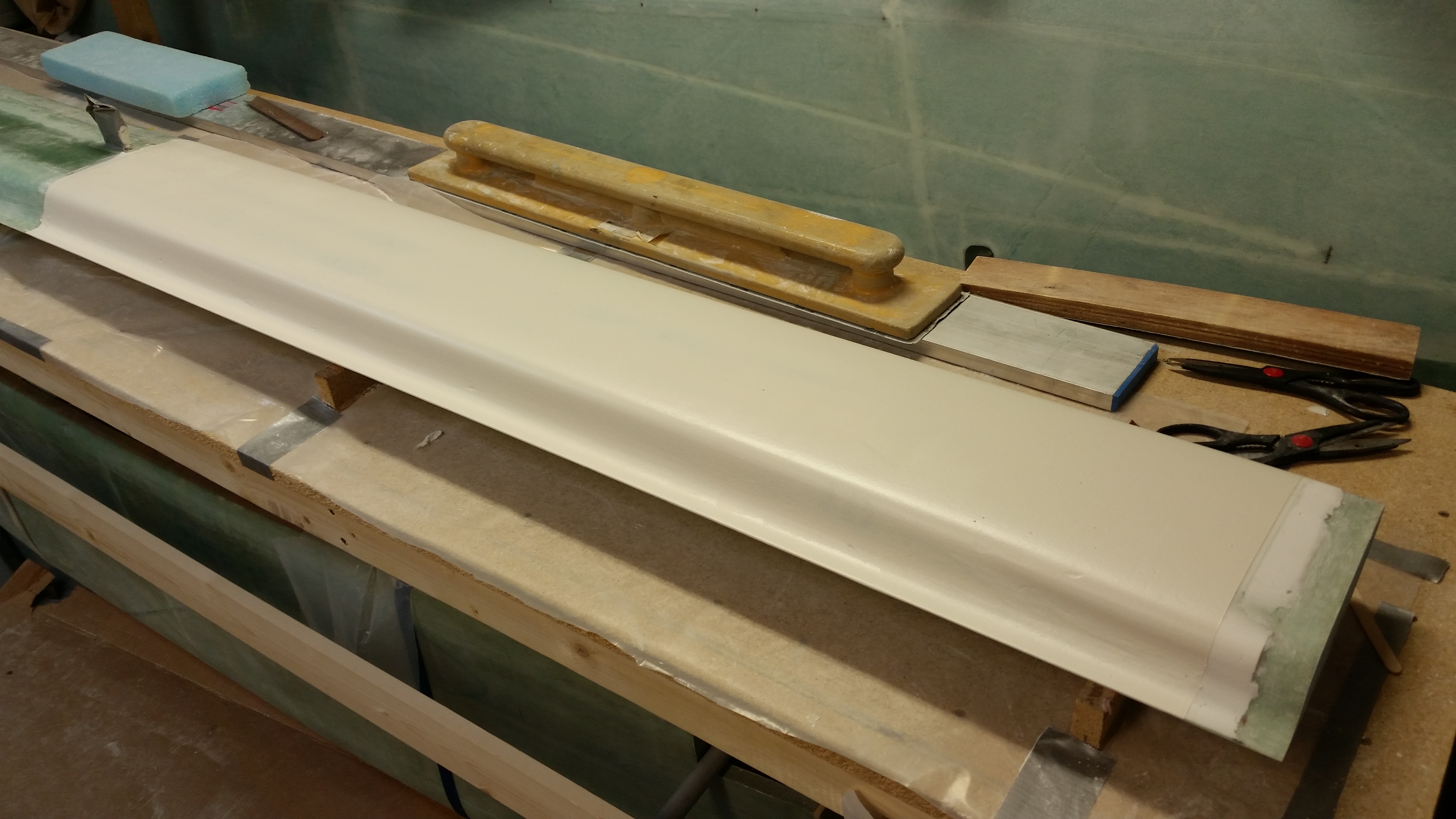
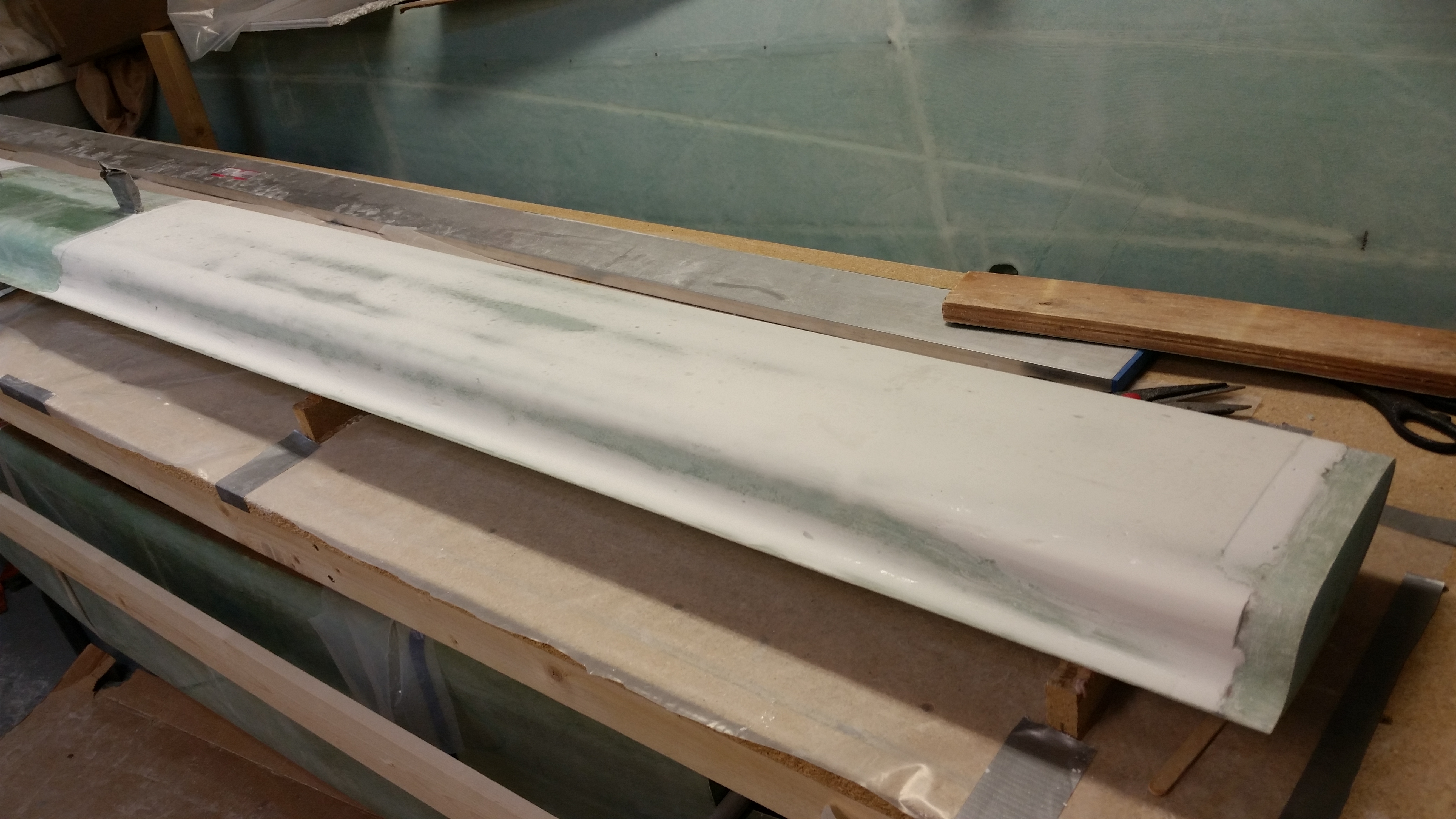
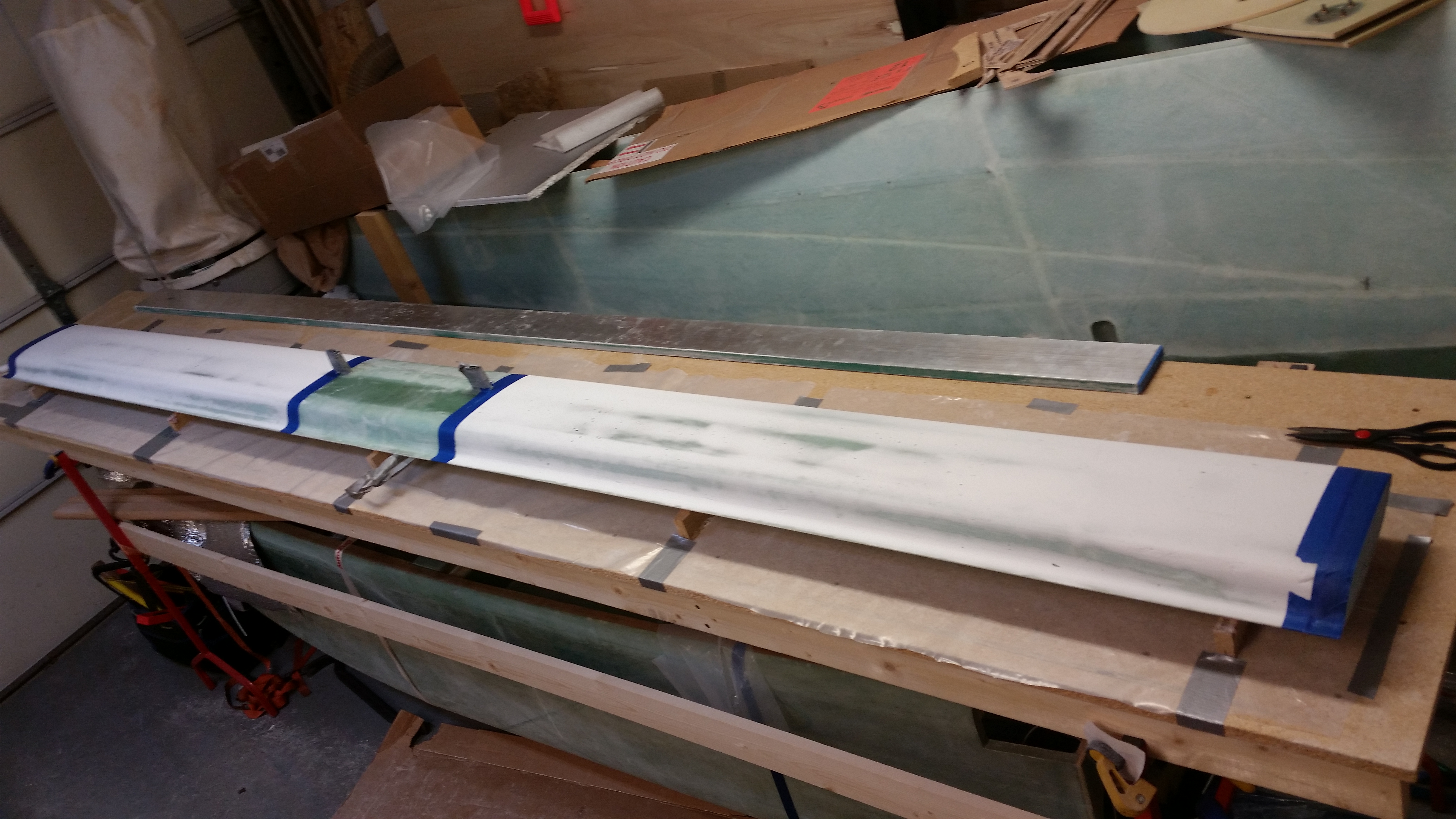
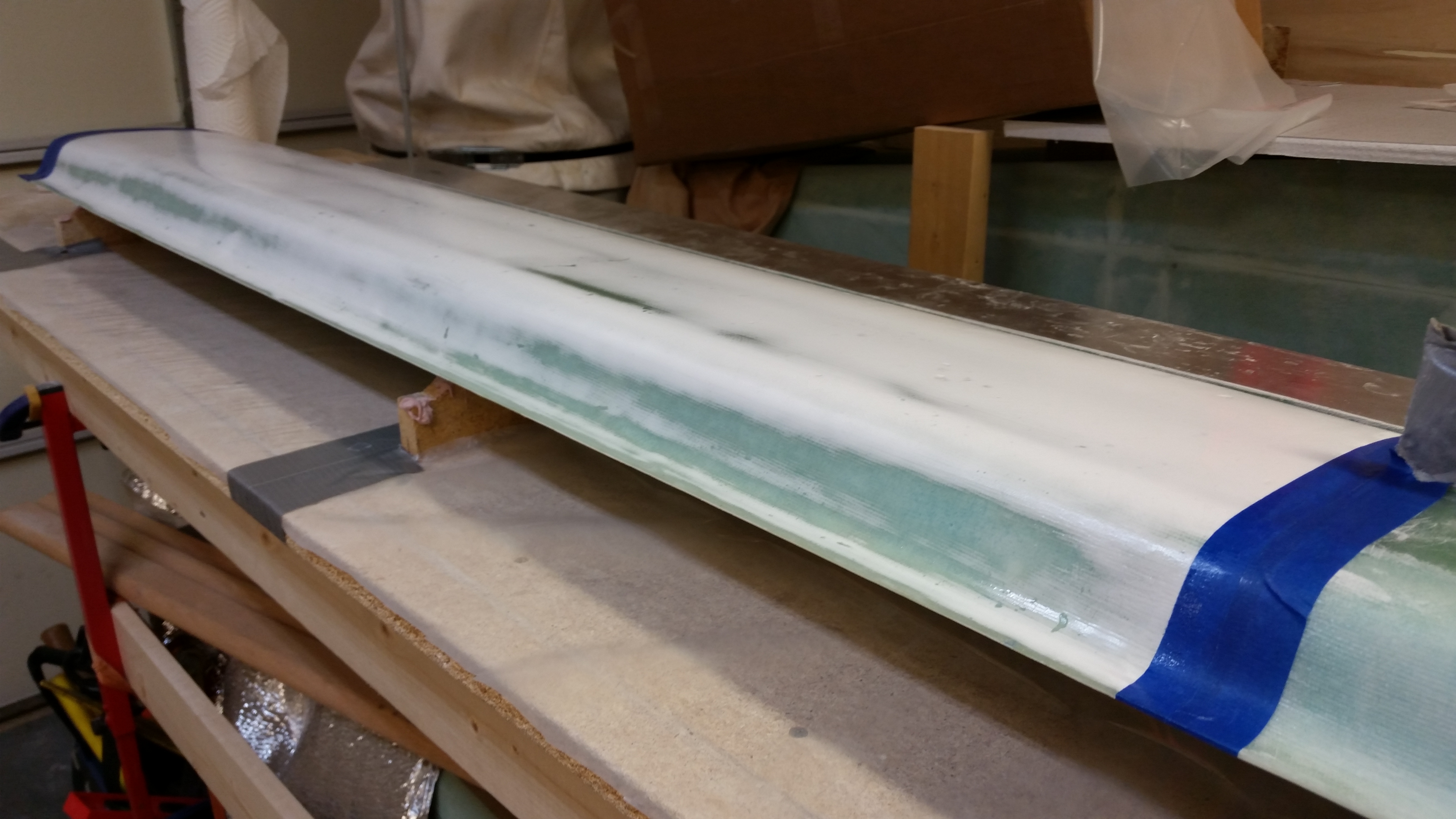
I started off today by hitting the cured micro on the elevators with my 36-grit sanding board.  After I got the edges somewhat feathered out & the ridges removed, I switched to a piece of 36-grit sandpaper that I simply wrapped around the curve of the front part of the elevators.  I then finished up with a few quick passes of 80 grit.  Below is a pic showing the comparison of the sanded elevator (top) to the other one still needing sanding.  Below that is a shot of both elevators’ sanded top leading edge micro strips.

Elevator front edge micro finish

Sanded elevator front edge micro

After sanding the front sides of the elevators, I checked the TE of the Right elevator.  Actually, I was checking the width from front to back along the entire span of the elevator just like I had done with the Left elevator.  Each end of the elevator was a tad thicker at just over 4.6″ wide, while the center of the elevator was 4.583″ wide.  I sanded the elevator on the edge of my long aluminum straight board that has 80 grit sandpaper tacked to it ( I bought this in Germany, and yes, still thinking it’s awesome!).  After a few minutes of some very careful sanding, I had the ends narrowed to 4.589″ on one end and 4.587″ on the other.  I figured that I would stop while I was close and not muck it up by going too far.  Now both my elevator widths are confirmed in specs.

After sanding the elevators, I took a break from sanding to Alodine the elevator spool tube. Although I would have preferred to wait until I cut this spool tube to length before Alodining it, the weather here in northern Virginia is getting cooler by the day.  So, while it was an absolutely warm gorgeous day I figured I would Alodine the tube and get it out of the way.

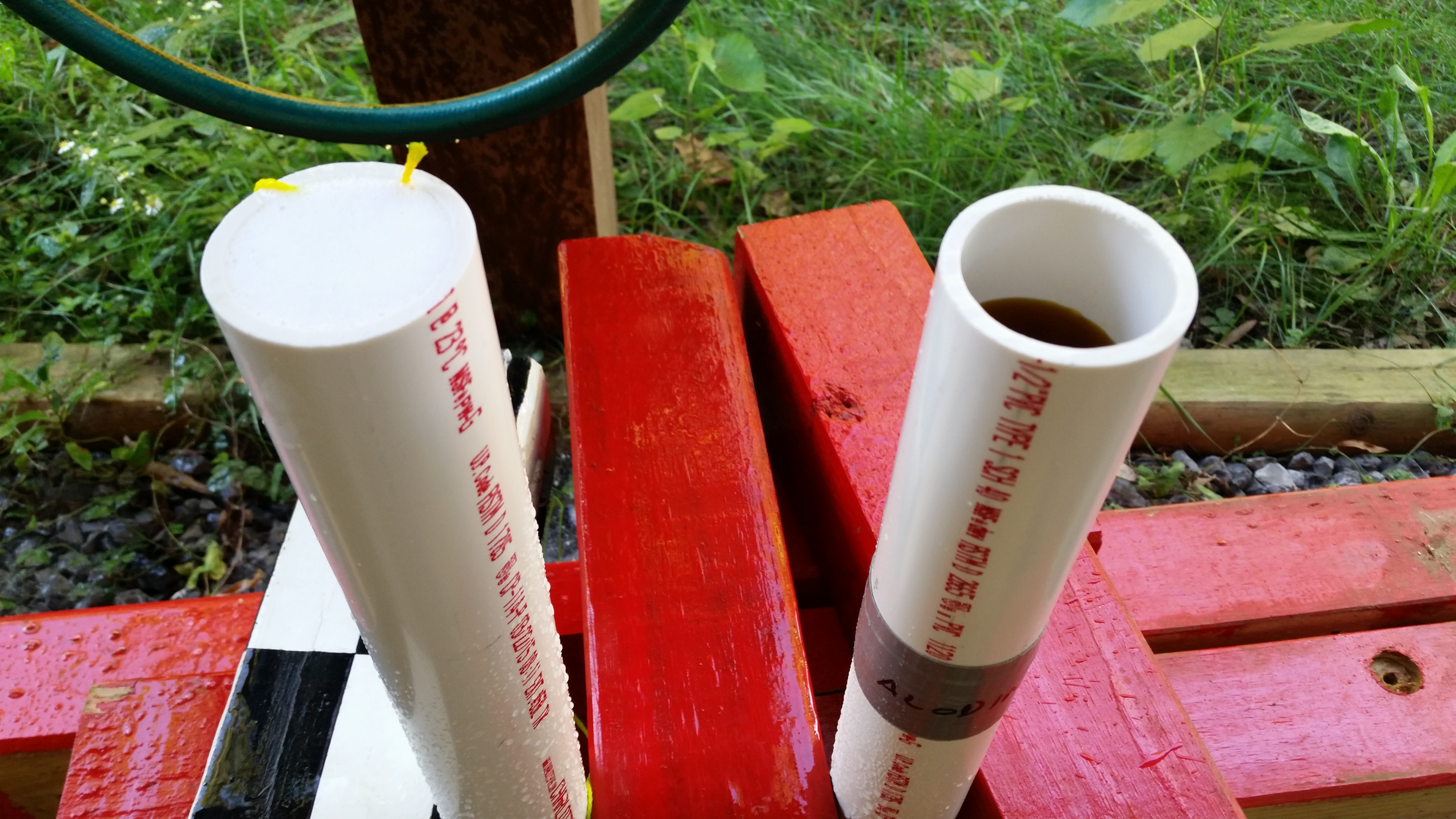
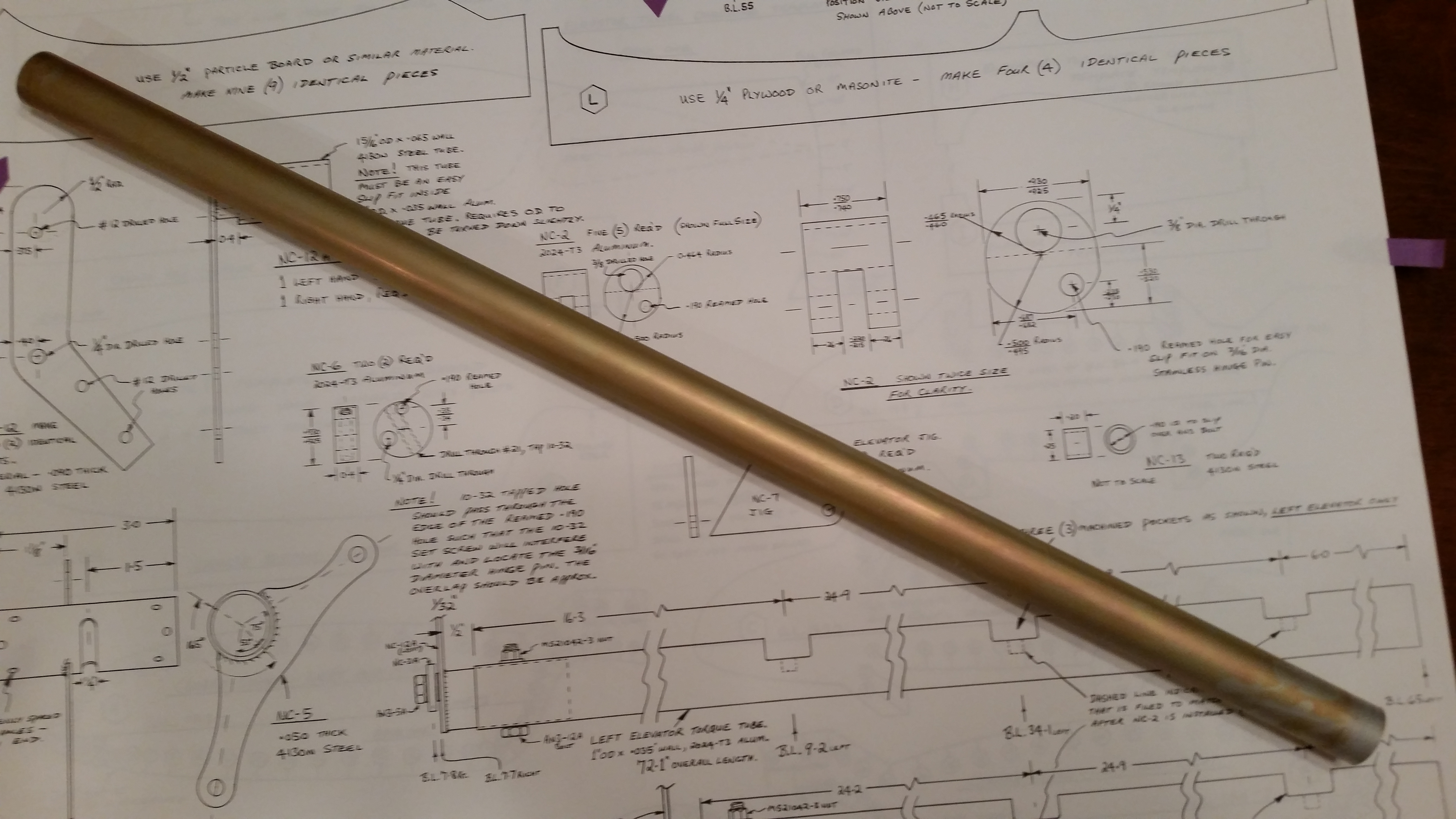
I had some 1-1/2″ PVC on hand, so the other day I bought two end caps.  I cut the PVC into two 24″ lengths, wrapped an end on each tube with some sealant tape and secured the end caps.  I then deburred one end of the spool tube, gave it a quick wipe down with acetone, and then cleaned it thoroughly with Simple Green.

I grabbed the tube, along with my Alodine & Alumaprep, some thick rubber gloves, the rest of my gear and headed to the back yard.  I will tell you that although I’ve stored my chemicals in a cool dark place it’s very noticeable that my Alodine & Alumaprep are really getting stale.  Instead of the stated 2 minute soak time (personally, I’ve seen 3-4 min ranges normally) in the Alumaprep & Alodine, it took almost 10 minutes each to get a decent clean & color on this spool tube.  No worries, I guess the stuff is still doing it’s job, it just takes a little longer. Kind of like me as I get a little older!  Ha!

Alodining elevator spool tube

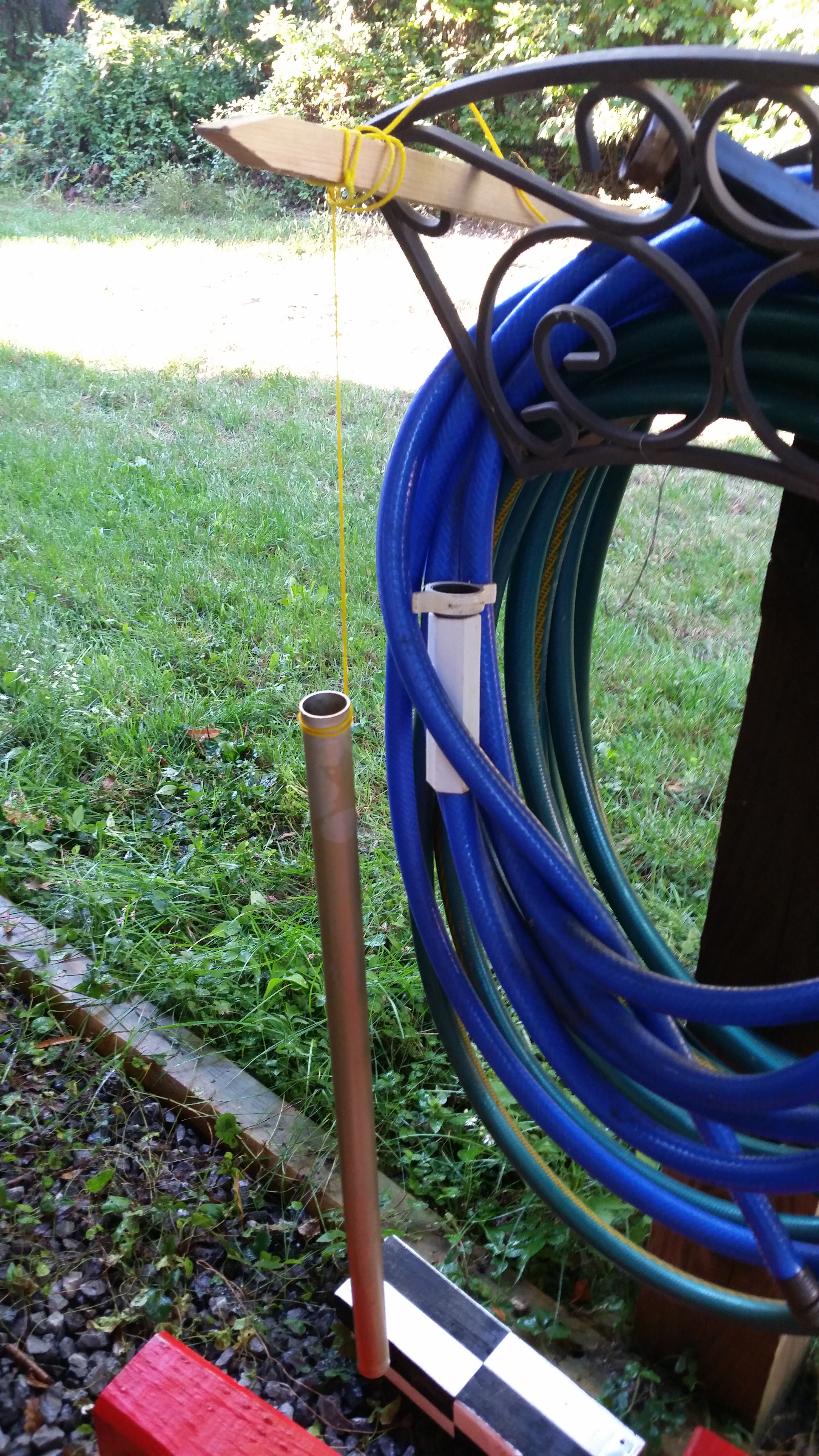
Since about 5-6″ of one end of the spool tube will be getting cut off (the side I didn’t deburr), I used this end to handle the tube & tie string to for dunking it into the solutions, and for suspending the tube as it dried.

Alodined elevator spool tube drying

With the spool tube Alodined, and after a quick project update and Airdog Aircraft Factory tour for my neighbor, my next task was to give the canard’s primer coat a thorough sanding.  When I last sanded it Saturday evening by hand, I could tell the primer was pretty tough stuff.  This time around I wasn’t going to mess around with the time consuming, more exhausting process of hand sanding, so I pulled out the big gun: my DA sander.

I started with 100 grit on the DA sander and hit both L & R sides.  It worked like a charm and took no more than 10 minutes per side.  I then followed that up with 150 grit paper on a pad sander, which I was able to use more effectively on the fishtail TE area.  I realize when looking at the pics that there seems to be a fair amount of coated material in the TE trough area, but I would rather start from a normal application of finish material and have to remove more of it during the elevator mounting process (to meet the .2″ gap requirement) than to assume it shouldn’t be there in the first place and not finish the TE area, as I have seen some other builders do it.  Not calling it right or wrong, just a personally preference.

Canard primer finish sanded

I vacuumed the canard surface and the surrounding area, and then pulled out the “L” templates for mounting the elevators to the canard.

Prepping to mount elevators

A shot of the “L” templates mocked up in place.

Mocking up elevator "L" templates

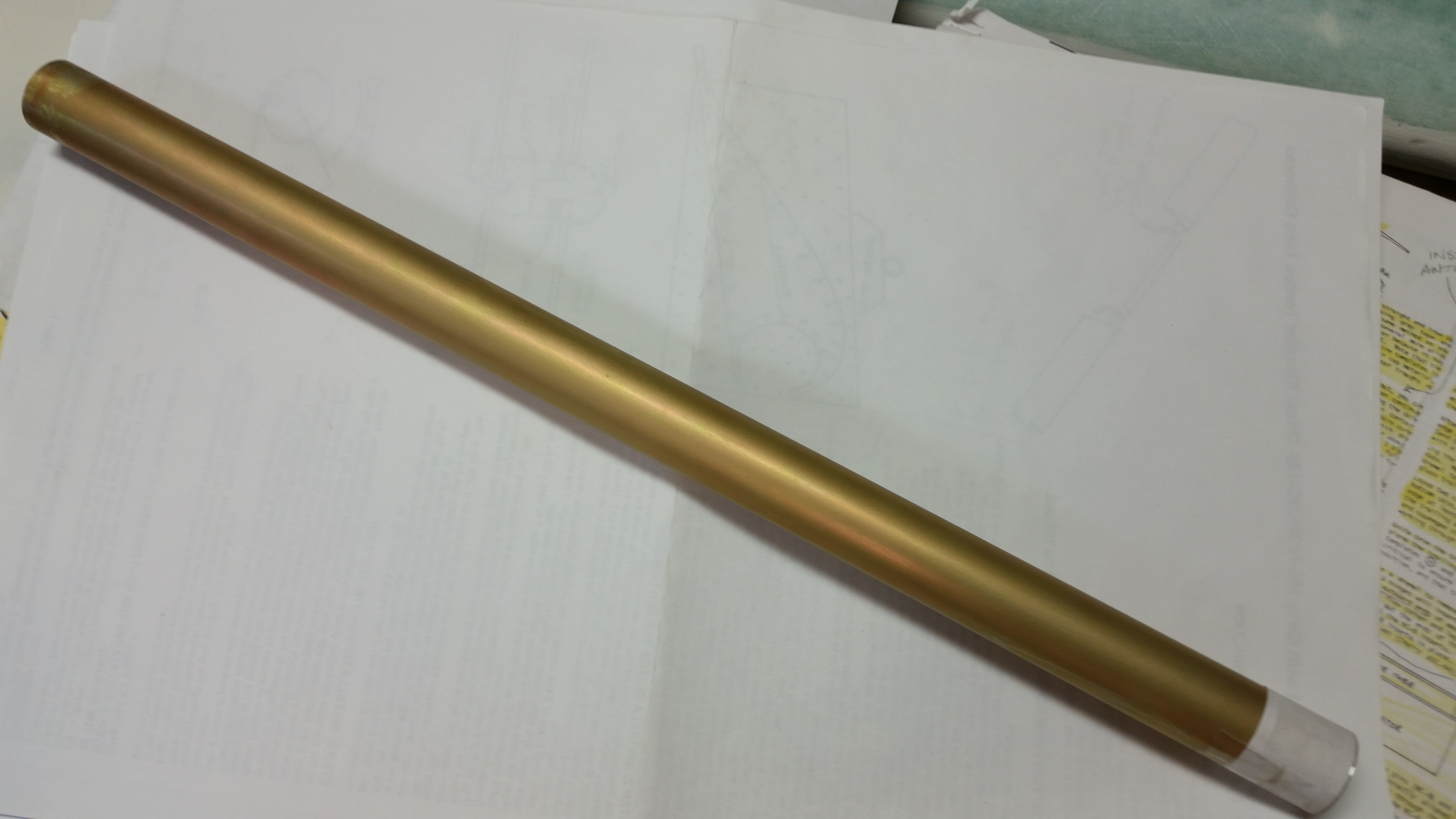
And a shot of the Alodined spool tube.  [NOTE: As a reminder, this spool tube is not per Long-EZ plans.  This is a cross tube used between the elevator offsets in the Cozy.  These offsets are manufactured by the Cozy Girrrls and provide two distinct advantages over the plans’ Long-EZ offsets:  1) The big advantage is that the configuration of these offsets is one that requires a much, much smaller hole in the sides of the fuselage to manipulate the elevators. Meaning less cold air!  2) With an offset on each side of the fuselage (versus just the right side on the Long-EZ) there are more options to mount direct drive control arms such as pitch trim, autopilot servos, etc.  Lastly, although not necessarily an advantage, I do like that the entire elevator configuration is symmetrical.]

Alodined elevator spool tube

With the bottom surface of the canard now finished to primer, I don’t want to bondo anything (i.e. “L” templates) to the surface of the canard just to have to clean it up later & risk messing up the finish.  For this reason, ala my friend Dave Berenholtz’s method I will simply keep the “L” templates in place by weighing them down.

So as I was out & about tonight I stopped off and got the materials & supplies required to make some sandbags.  When I get those made tomorrow I’ll start on the journey of installing the elevators to the canard!


Chapter 10 & 25 – Le Primed “Duck”

Or, as they say in France, “Le canard, oui?”

I started out today by giving the epoxy skimmed canard a thorough sanding.  First off, I was checking out the surface in the light and realized it was still just a tad too lumpy across the board to my liking.  So I backed up one step and grabbed the marine long board with 80 grit paper to knock off some of those surface irregularities.  I did a pass 45° to the right and then 45° to left on each side.  After knocking down the surface significantly with the 80 grit paper, I hit the canard with 100 grit sandpaper two complete passes on each side and then I finished up with a couple of passes using 150 grit paper.

After the final sanding down of the epoxy skim coat & Micro Skim I vacuumed the canard and the surrounding area, cleaned the canard and let it dry before taping it in preparation to prime it.

Prepped to Prime!

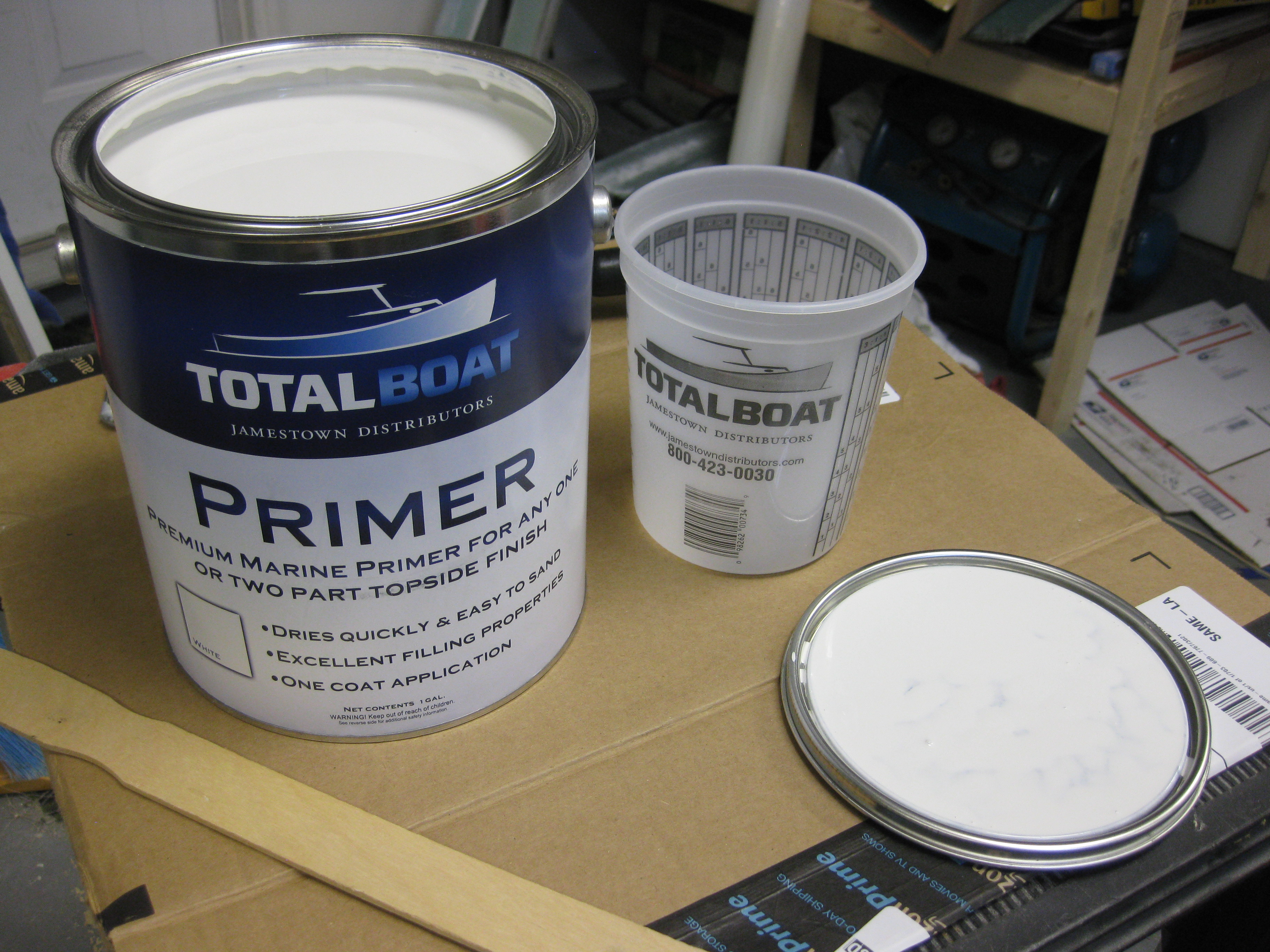
As I posted earlier this year, I made a decision to use boat paint for the final finish on this Long-EZ.  Unless it proves unsatisfactory I’m keeping with that decision due to low cost & ease of application.  Here’s a shot of the opened can right before I started priming the canard.

Total Boat Primer

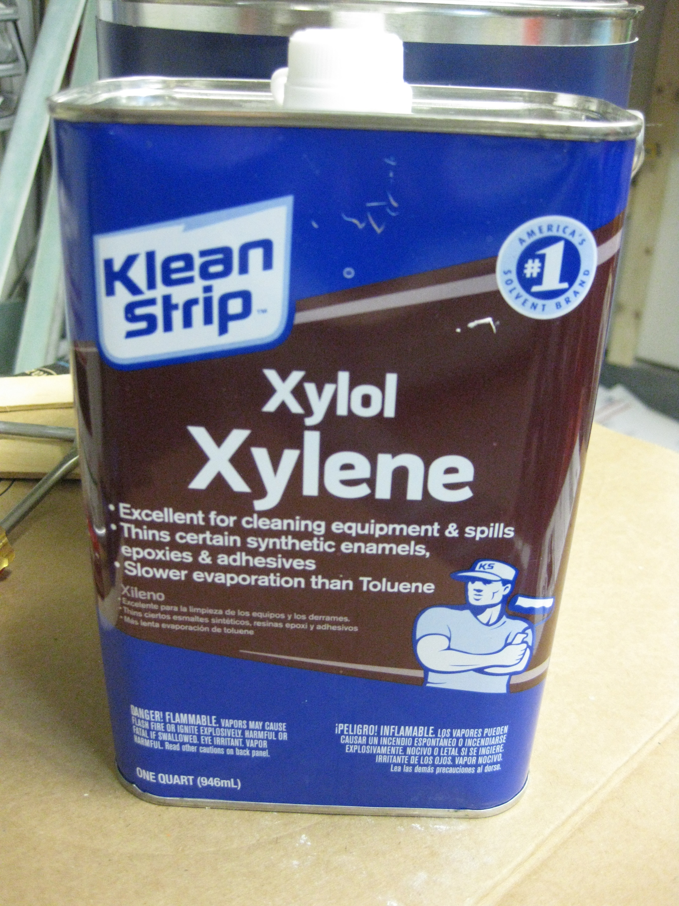
Jamestown Distributors, the company who sells Total Boat paint products, recommends using Xylol/Xylene to thin the primer.  Since I didn’t have any Xylene on hand, and only just learned about it by watching the how-to video on Jamestown Distributor’s website, I decided to make a lunch/Home Depot run.  I carted the above pictured gallon of boat primer down to Home Depot and as I was shopping for various paint supplies had them shake up the can for me in their Über-duber mixing machine.

Used to thin primer

After grabbing a quick lunch & returning back to the shop, I thoroughly stirred the primer, mixed it with 10% Xylene and applied the primer to the canard with a foam roller.

Some of you may wonder why I’m priming the canard at this stage.  Well, it seems there is a common difficulty in getting the gap between the elevators and the canard just right. Thus, I want the gap to be a known quantity before I start.  I don’t want to declare that a 0.2″ gap is in hand only to find that when I finish the canard and elevators that it’s only a 0.18″ gap, just as an example.  Also, as I mentioned before, I believe Randi from the Cozy Girrrls when she says it’s infinitely easier to sand & finish the canard bottom when there are not 6 protruding elevator hinge tabs sticking out of the bottom of the canard.  And since I want to get the canard as smooth and as prepped as possible for paint, then the primer needs to go on before the elevators get mounted.

Below are two shots of the canard after the primer was applied.

Primed Canard

Primed Canard

I took this pic of the trailing edge just to provide a general idea of the straightness of the canard.

Primed Canard

As well as this shot of the LE.

Primed Canard

Here’s a shot of the canard after I pulled the tape and sanded it with 100 grit sandpaper. The specs sheet said it should be ready to fully sand after 90 minutes, but even about 2.5 hours later I could tell it was just a tad bit gummy.  Since it wasn’t fully cured, I only focused on sanding the very bottom surface and left the fishtail TE area until tomorrow after it cures more fully.

Primed & sanded Canard

Here’s a shot of the other side after having been sanded with 100 grit.

Primed & sanded Canard - tape peeled

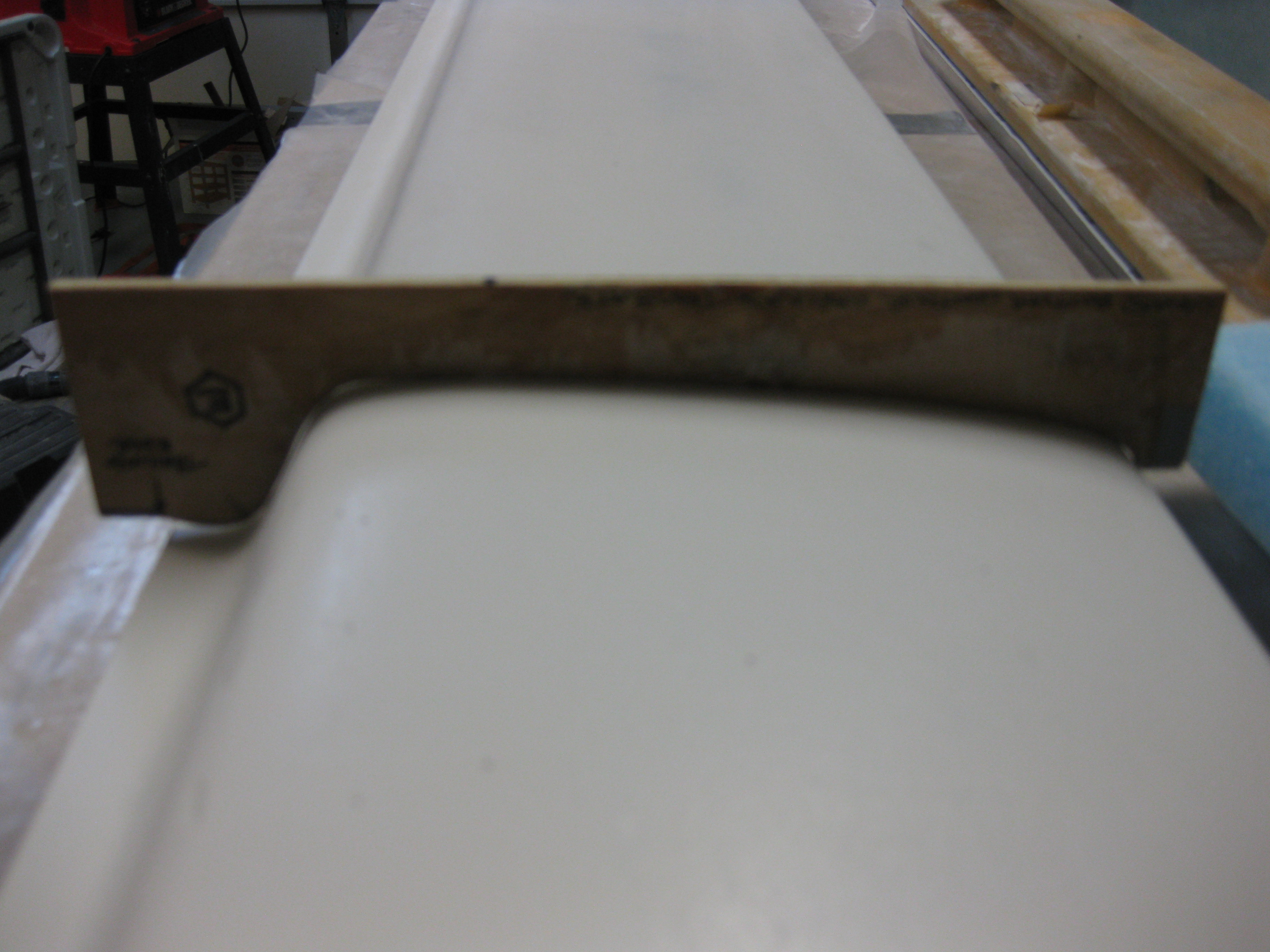
And a quick double check with the lower canard contour template showed that my lower canard is pretty darn close to specs.  The TE is a just a bit high on the back end, but I confirmed with Feather Light years ago that this is within tolerance.

Bottom canard contour template check

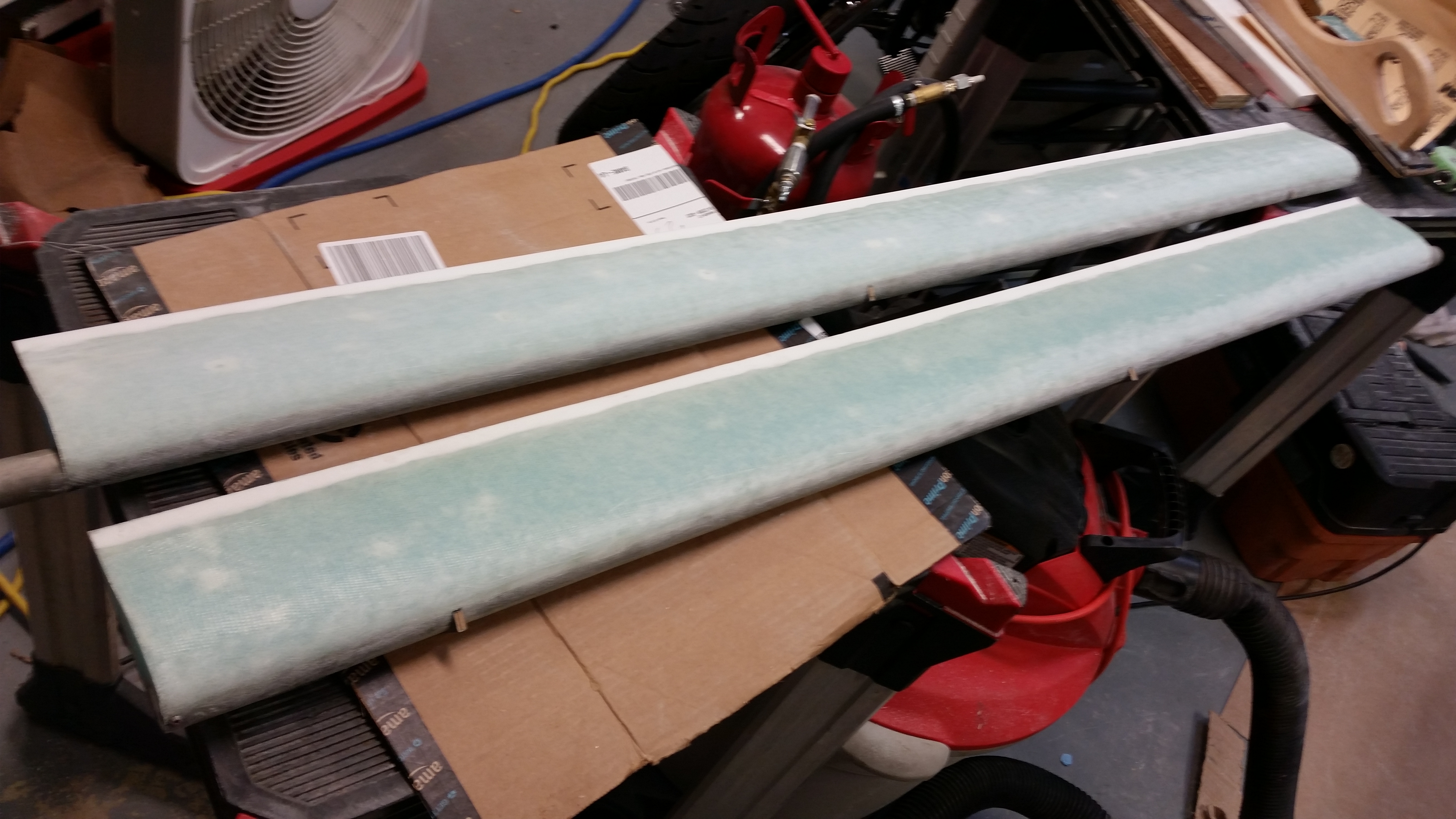
After I sanded the canard with 100 grit sandpaper, I finished sanding the slight span-wise trough in the right-side elevator in preparation for applying micro along the trough on each elevator.

Elevators sanded

Below is a pic of the applied micro in those troughs.  Once the micro is sanded, the elevators will be ready to mounted to the canard.

Fixing my "dented" elevators

I waited about 2-1/2 hours and then sanded the micro in the trough while it was in it’s “green” stage.  Unfortunately, it was only at the very beginning of the “green” stage and was still a bit more gooey than rubbery.  But, since it was late, I sacrificed the already well-used piece of 36-grit sandpaper on my sanding board to plow through the gooeyness and knock down the ridges and lumps on the elevator rounded leading edge.

Elevators sanded while "Green"

The next step is to re-sand the primer on the canard until it’s smooth.  Once that is complete, I’ll sand the micro I just added to the elevators.  After those two tasks are complete, I’ll be working on mounting the elevators onto the canard.

Chapter 10 & 25 – Sanding my life away…

Last night I had a couple of buddies come over to watch Thursday night football.  In between the beers, war stories and game, I snuck down to the garage every couple of hours to skim coat the canard.  Well, a late night socializing with good friends that I haven’t seen in a while meant a slow start this morning.

To add to my slow start, I had a business teleconference today and when I finalized yesterday’s post by adding another menu item to this web site, the main menu went bonkers.  My “new” main menu contained every menu & submenu item listed where the main menu bar is normally located.  I don’t know if you saw it, but it was a hot mess.

After messing around some with WordPress to see if I had checked some weird block or initiated some obscure setting, and then doing some Google research, I got on the phone with my service provider to have them increase some site server settings to allow for more menu entries.  Well, that call took 40 minutes the first time around and I was on hold after being transferred to technician #2 when my work teleconference started.  So I got off the phone and an hour later called back to resume my website troubleshooting.  I finally got the menu bar back to normal, but not without some collateral damage.  My video/pics and contact menu tabs were both missing and re-adding them was not without issue.  Thus, I will slowly try to get the website ship righted while continuing to add content.  Thankfully, most of the remaining issues are minor.

After a little bit more information crosschecking on finishing steps & techniques, I headed for the shop to block sand the cured skimmed epoxy.  Since I don’t have any specialized sticky back (PSA) or velcro (HookIt) 100 grit sanding sheets, I had to resort to the old style sandpaper sheets.  This actually worked out pretty good since I grabbed a scrap block of blue wing foam about 6″ wide, 12″ long and 2″ thick to use as a sanding block.  The 100 grit sandpaper wrapped around the foam so I could firmly grip the paper around the foam and still keep control of the foam block while sanding.

I started on the pure epoxy skim coated side and started sanding away in the 45° left and 45° right pattern.  I’m learning that all the sanding during these finishing steps seem to start off with not much happening, but as you just keep working the sanding block you really start to see some results.  Of course the most time spent on the underside of the canard is in the TE area.  The multiple curves and angles make it a bit more challenging to get the fishtail area sanded thoroughly.  But after I was finished, and just as Mike Beasley mentioned the other night, I couldn’t stop running my hand over the incredibly smooth canard surface.  What a feeling to turn a raw glass surface into something that you know that once painted, will turn into a something stunningly beautiful.

All in all I was extremely pleased with the outcome.  Although my initial failings in applying bubble free micro led to having a dozen or so craters on each side of the canard (this was due to applying too dry of micro after aggressively whipping a ton of air into the mix), it was a good learning lesson since I know now how well both skim coating and Micro Skim fill in some major surface defects in the micro.

Epoxy coat sanded - 100 grit

After sanding the pure epoxy skim coat, I was eager to see how the Micro Skim was going to sand out.  Well, just like the other side it started a little slow, but then starting sanding out a little more quickly than the epoxy skim coat.  To be fair, I don’t think there was any clear winner here between the pure epoxy skim coating and the Micro Skim, since they both produced very acceptably nice results.  I’ll still continue to experiment with these two methods, and I’m thinking as my finishing skills improve I’ll be better able to both tweak the process and ascertain the results.

Micro Skim sanded - 100 grit

My plan for tomorrow is to finish round 2 of sanding the canard with 120 grit sandpaper, and then finish sanding, prepping and micro-finishing the front top “corner” of the elevators to get them ready for mounting to the canard.

Chapter 10 & 25 – Canard Wipe-out!

Last night I had a fairly lengthy discussion with my buddy Mike Beasley on the finer points of finishing the composite surfaces on Long-EZs.  In fact, at Christmas-time last year, Joe Caraggio went down to Georgia (does that make Joe the devi . . . hmmmm? Interesting, but I digress) to assist in Mike in finishing (as in micro) his bird.  So, during my discussion with Mike I got both his take and a lot of what he picked up from Joe on finishing techniques.

In addition, after having met the venerable Terry Schubert (Editor of Central States Association newsletter) at Rough River, I’ve been leaning on his guru-ship as well to ensure I don’t muck anything up!  Terry has been very generous in offering me advice & info that has greatly facilitated my build progress.

Let me reiterate: this is the first round of finishing that I’ve done (ever!) and obviously the finish is the one HUGE thing that people see right off the bat when they look at your airplane.  It doesn’t matter if the underlying construction of your airplane is strong or weak, or that it’s a thing of beauty or crying out to be covered in gobs of paint to hide its hideousness . . . none of that is truly judged when your bird is sitting on the flight line somewhere.  Again, what is judged is how the surface & lines of your airplane flow, and how smooth & glossy the finish is on your paint job.

Thus, I want to get this finishing thing right from jump street.

So let me get off my soapbox and on to the build!  Today I started out by taping up the outboard and inboard edges of each side of the canard.  The outboard edges need to be epoxy free so that I can of course glass on the Roncz canard swoosh tips after I’m finished installing the elevators.  Once the canard swoosh tips get glassed in place, then I’ll finish them as well and blend them into the existing finish on the bottom of the canard, and the top of the canard too for that matter.

The inboard areas will get smoothed out and feathered into the non-finished interior of the canard.  This middle area doesn’t get finished to save weight, since once the canard is mounted it remains ‘buried’ & hidden inside the confines of the fuselage.

Skim coating micro finish surface

Now, I performed a little experiment on the bottom of the canard with the next step of finishing.  On the Left surface in the photo below (which is the Right-side bottom of the canard), I used the now standard traditional Cory Bird method of wiping on 5 separate applications of pure fresh West epoxy, with an approximate 2-hour cure time in-between. Just as you might cheese grate the micro finish on the surface of the component after it has cured for around 2 hours so that it’s in the “green” stage, so too we let the pure epoxy cure to a “green” state before adding the next round of epoxy.

Thus, the picture below is the first application of pure epoxy onto the finished & cured micro finish.

Skim coating (aka epoxy wipe)

If the Cory Bird method is test subject A, then Nate Mullins’ Micro Skim method is test subject B.  Nate claims on his site that Micro Skim really cuts down on the post-sanding effort after the skim coat is applied.  After talking with Nate about this method shortly after he developed it, I figured I would try it out on my first skim coat endeavor to see if it really is easier, and if so, perhaps save a fair amount of time & effort in finishing my bird.  The essence of Nate’s Micro Skim coating method is simply adding a little bit of micro to the pure epoxy.  The amount of micro is way less than what you add even for a micro-slurry, but just enough to give the epoxy a little bit of thickness when applied to the surface of the finished part.  Application is a little easier since you simply roll on Micro Skim with a foam roller, whereas with the pure epoxy skim coating you are using a squeegee to apply the epoxy onto the surface (to be clear, some builders like Wayne Hicks have used a foam roller to apply to the epoxy skim coat and then used a squeegee to skim the excess epoxy off the surface).

Thus I used Nate’s Micro Skim on the Right side of the canard in the pictures (which is technically the L-side bottom of the canard when mounted).

BTW, the resulting finish of the Micro Skim, not surprisingly, is much more grainy and opaque than is the pure epoxy skim coat.  Again, the proof will be in the actual sanding & quality of surface finish after these two sides have cured and are block sanded.

Nate Mullins' Micro Skim

Here’s a shot after 3 coats:

Third coat of fresh epoxy applied!

After I applied the third coat on each side, I started work on the Left elevator to get it ready for finishing.  I double checked the width of the elevator and ended up sanding the trailing edge to get it to a uniform width along the whole length of the elevator.  The outboard width of the elevator was 4.578″ inches wide while the inboard was 4.624″ wide.  After some very minor sanding, focusing on the inner 2/3rds of the elevator, I got the very inboard edge right at 4.6″.  With just a tad bit more sanding, while ensuring my TE was straight, I ended up with the inboard edge at right about 4.597″ …. less than 20 thou along that span is golden for me.  Any more sanding was just asking for a “chasing of the numbers” with the result being an elevator that’s too narrow.

I then started sanding then entire front nose area & top of the elevator.  Since I got the elevator foam cores from Feather Light, and since Feather Light uses the original Roncz elevator templates, a decent amount of foam along the razor-thin top front edge of the “C” shaped cutout (where the elevator tube is embedded) was broken off or torn away when I micro’d the foam to the elevator tube.  I think this is fairly common since using the original template results in that “C” channel just being ever so slightly too narrow for the elevator tube to fit into.  In other words, besides either cutting them myself and slightly modifying the channel before hot-wiring the foam, or using Steve’s Eureka CNC elevator cores, the bottom line is that minor carnage on each leading edge of the “C” channel was bound to ensue as the elevator foam is micro’d to the elevator tube.

Why am detailing all of this?  Because after glassing the elevator skins, there remains a very slight depression (trough, if you will) along the length of my elevator right at the top junction between elevator tube and foam core.  In the picture below, it is the line that is even with the top of the elevator hinge slot, and again, runs the full length of the elevator along the “nose”.  Also note in the pic below that the area to the left of the elevator hinge slot is sanded while the area to the right is not.

Prepping elevator for finishing

Back to the canard.  After applying 5 coats to each side (and also filling in the very outboard left aft “corner” of the canard with dry micro – see pic below) I waited for about an hour before pulling up the blue edge tape.  Below is the Micro Skim side about an hour after the final coat was applied.

Finished (5 layers) Micro Skim

And here is the pure epoxy skim coat side about an hour after the final coat was applied.

5 coats pure epoxy wipe (ala Corey Bird)

Here is the entire bottom of the canard after being skim coated & micro skimmed.

Candard bottom skim coated & micro skimmed

Although these are technically the next day, I added these two pics after the surface was pretty much cured.  Pure epoxy skim coat is on the left, micro skim method is on the right.

Five coats of pure epoxy appliedFive coats of Micro Skim applied

Now, on to the elevators!

Chapter 10 & 25 – Finishing Canard

I wasn’t able to get around to sanding the canard yesterday… but I was today!  I started out by reinforcing the workbench by adding a 1×4 cross support between the two table supports.

Workbench Stabilization

I then started back sanding the canard with the marine long block with 36 grit paper.

Marine long sanding block 36 grit

After I used the long sanding board, I used the contour sanding block with 36 grit paper.  I could tell by the sandpaper cut patterns in the micro that there was entirely too much micro build along and above the spar cap area, both on the left and right side of the canard.  I marked across the width of these prominent gouge line areas with a Sharpie so that I could use the long board to remove the excess micro above the spar caps.

R-side high ridge identified

L-side high ridge identified & marked

Here’s an “action shot” with the long board!

Marine long sanding block 36 grit

About 80% done here . . .

Marine long sanding block 36 grit

And voila.  I repeated this process –alternating between contour sanding block and long sanding board– a couple more times to remove micro from above the spar cap area on both sides of the canard.  This process did essentially two things:  1) It changed the profile of the lower canard to more closely match the “E” contour template by flattening the bottom of the canard and greatly decreasing the existing curve of the lower canard profile.  2) It optimized the TE shaping.  The flatter the canard bottom became and more in line to the “E” contour template, the more effective the TE edge portion of the contour sanding block became since it was able to contact that aft area of the canard more fully.

R-side ridge sanded down - Marine long board

And here’s a shot of the process on the other side of the canard.

Removing L-side micro ridge - Marine Long board

The canard after the second full round of sanding:

Round 2 Sanding Finished

And a closer shot of the lower right side of the canard after tonight’s sanding.

Round 2 Sanding Finished

I’m hoping to get a couple of epoxy coats on the bottom canard micro finish tomorrow… schedule allowing.