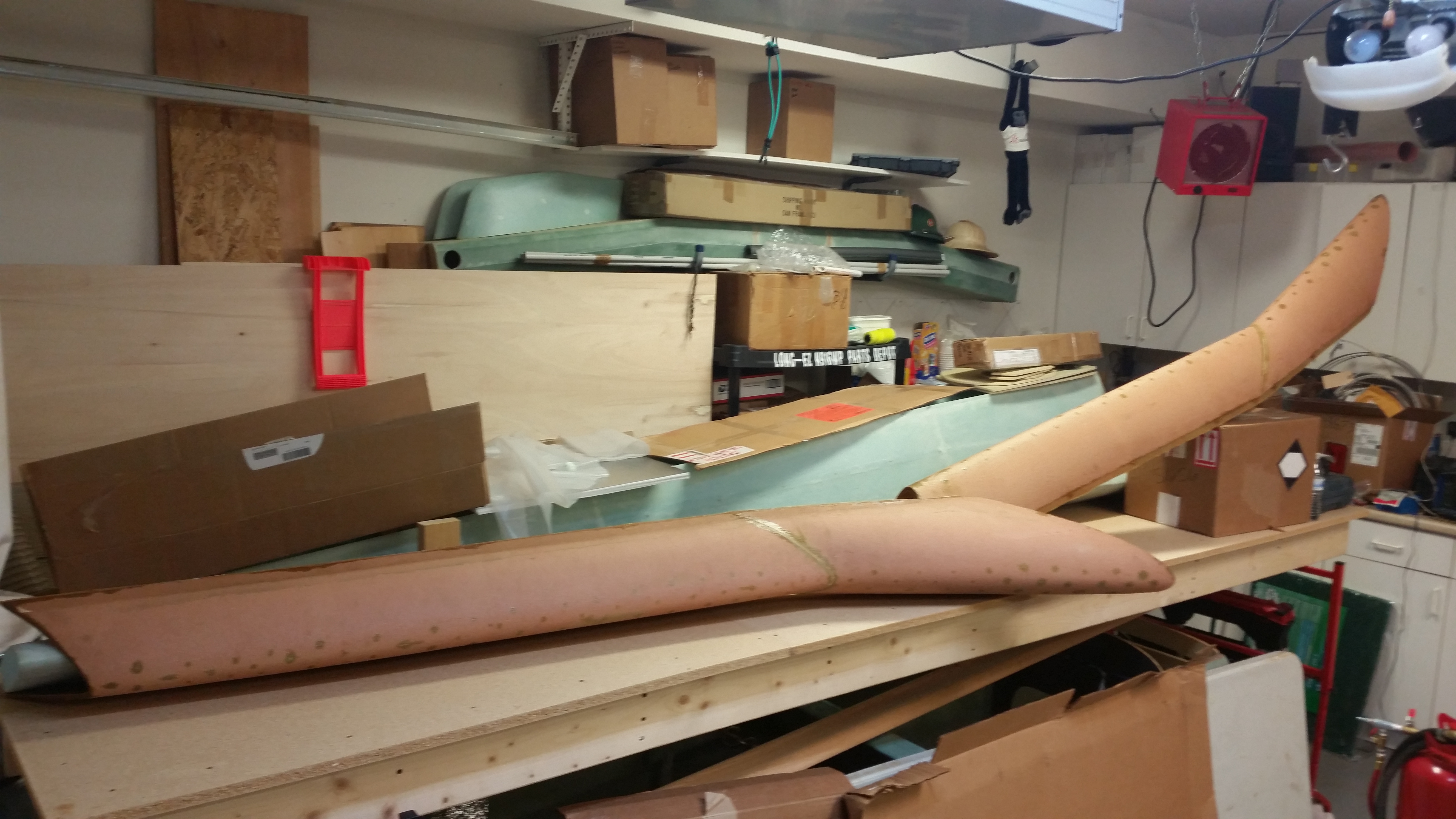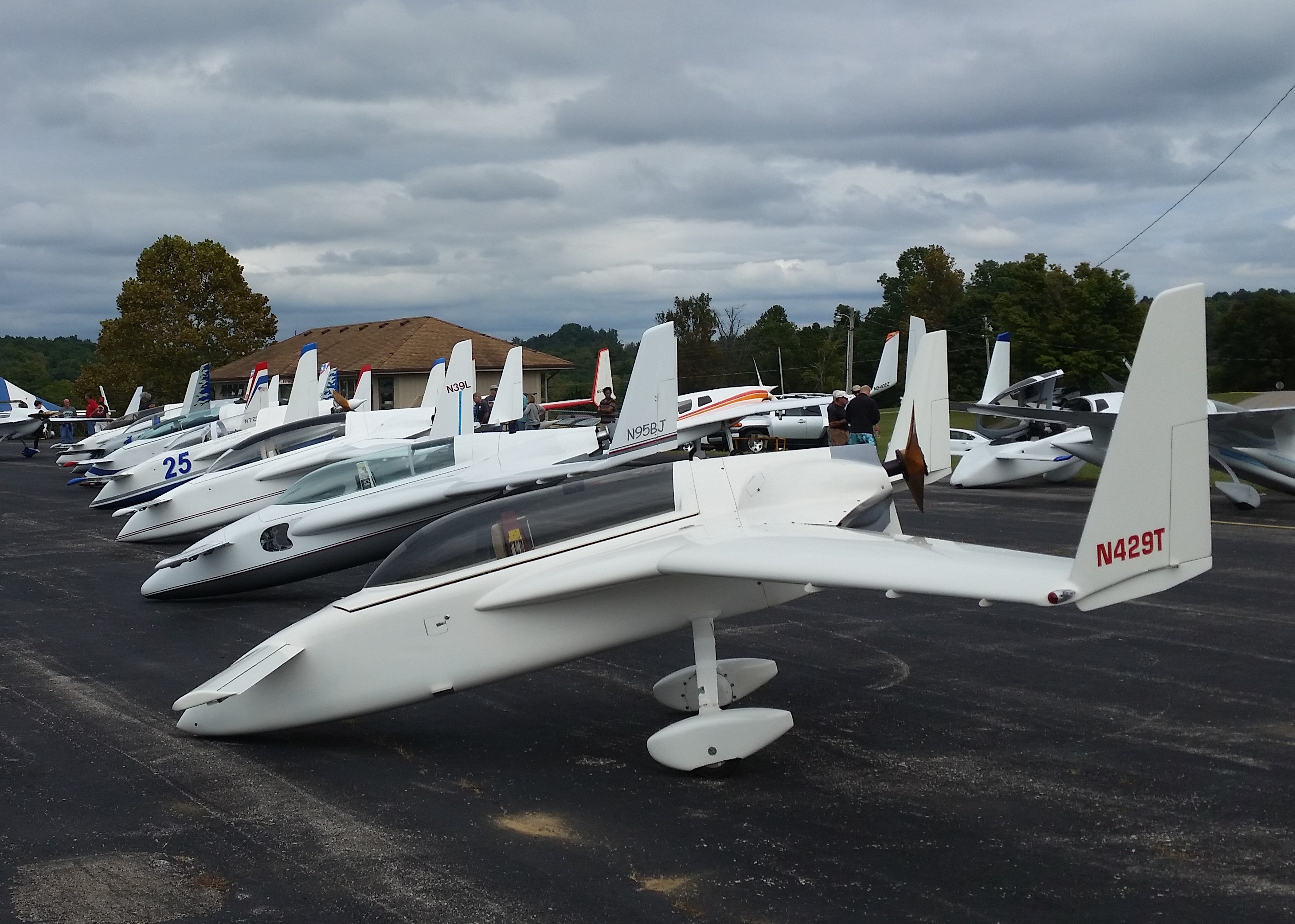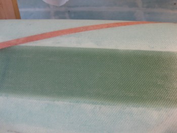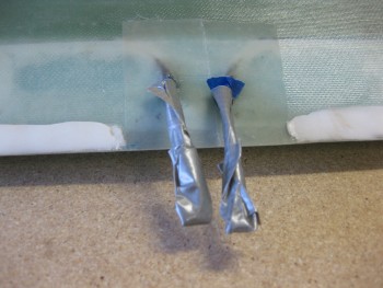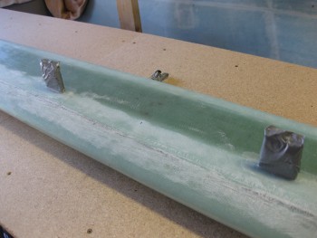
Chapters 10 & 25 – Finishing Canard

Today, before I changed into my full grunge sanding clothes I ran out to Harbor Freight to pick up some finishing supplies.  Instead of using the construction-type wall mud compound taping knife for applying the micro finish, I wanted an applicator with a low profile handle vs. the one long center handle.  I found exactly what I was looking for in the automotive section with the Bondo applicators.
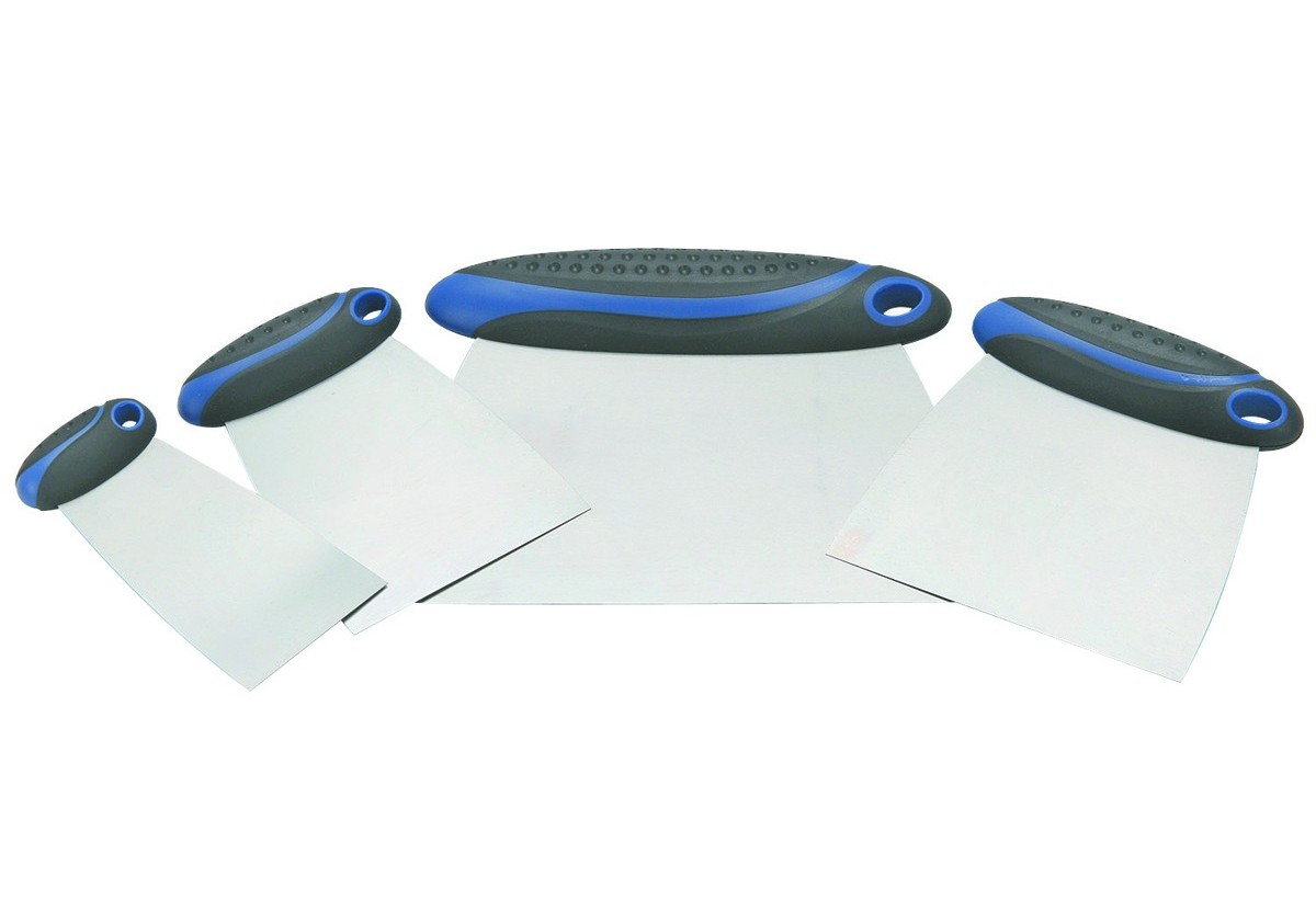
Harbor Freight Bondo Applicators

Upon returning home, I got to work on sanding the micro’d bottom of the canard.  I quickly realized that I have plenty of micro on the surface.  I’m fairly certain that I’ve definitely met the “it’s better to have too much micro than not enough” criteria for finishing Long-EZ surfaces.  The micro build is fairly thick, and although it may take an extra hour or two to get the surface sanded down to the right depth, in the long run it will be worth it since it will minimize rework & refilling.

The contour sanding block worked well.  I can see where another inch in width would make it just a hair more stable in tracking the surface, but the advantage of the slightly narrower sanding block (as compared to Wayne Hicks’ 3-3/4″ wide block) is that I would think that the effort is much less to work it since there’s less sanding surface area.  I can see where it would be nice to have a wider sanding block towards the end of the sanding cycle when the finer, higher grades of sandpaper are used.

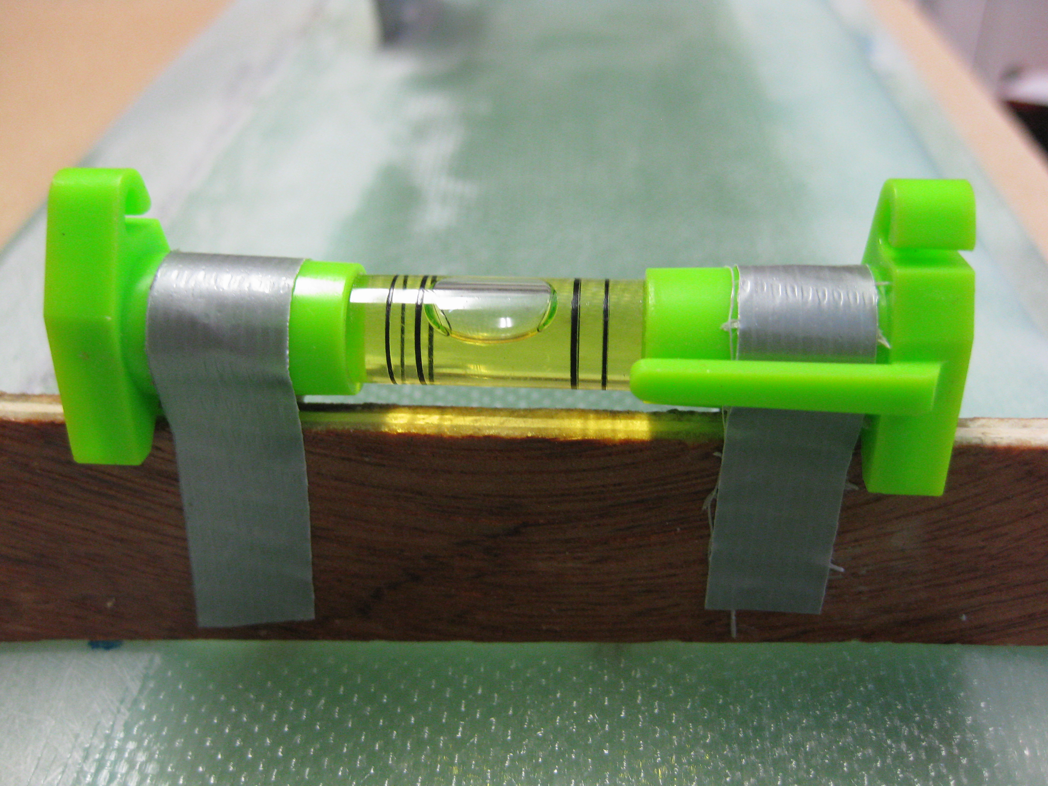
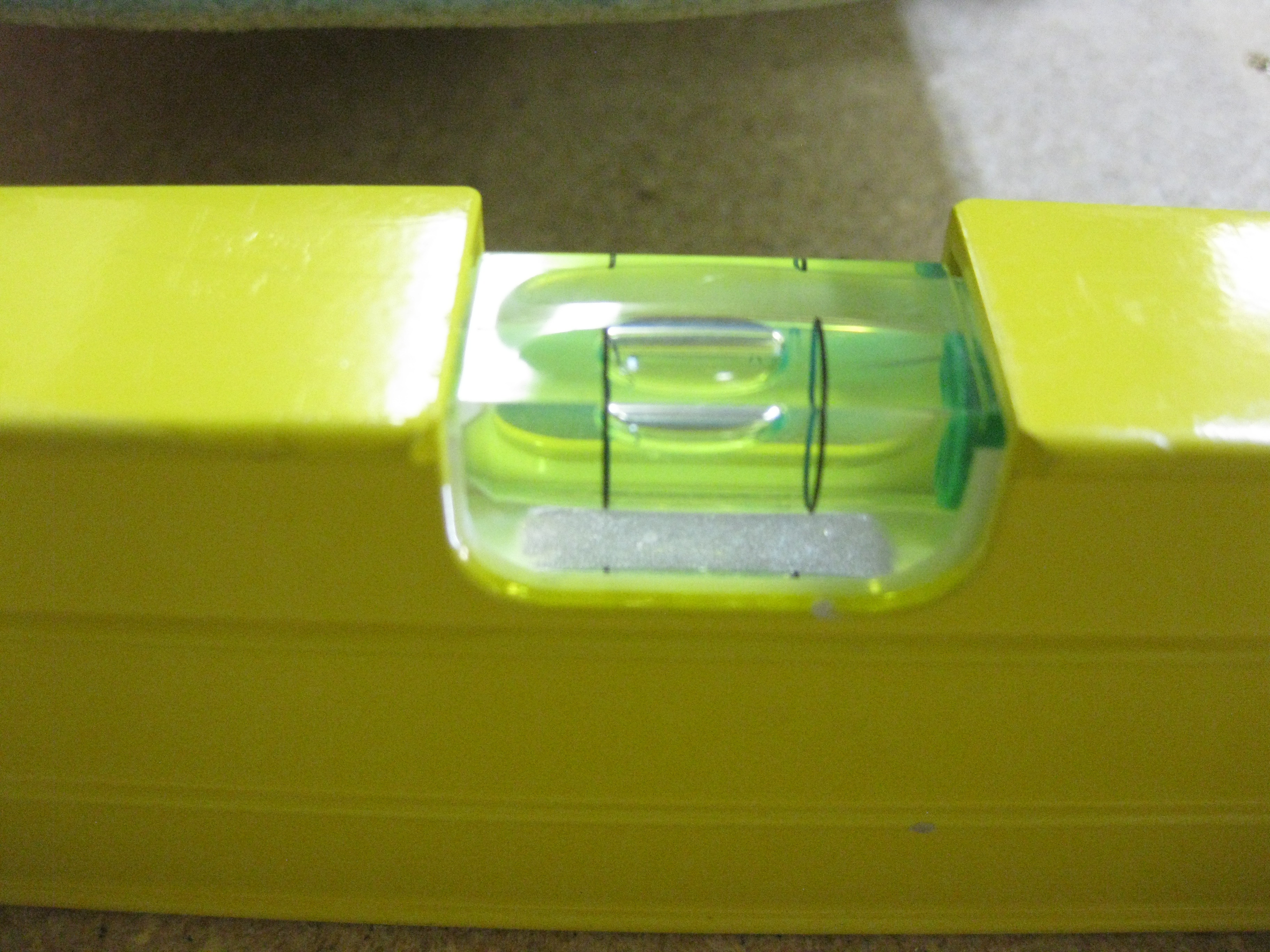
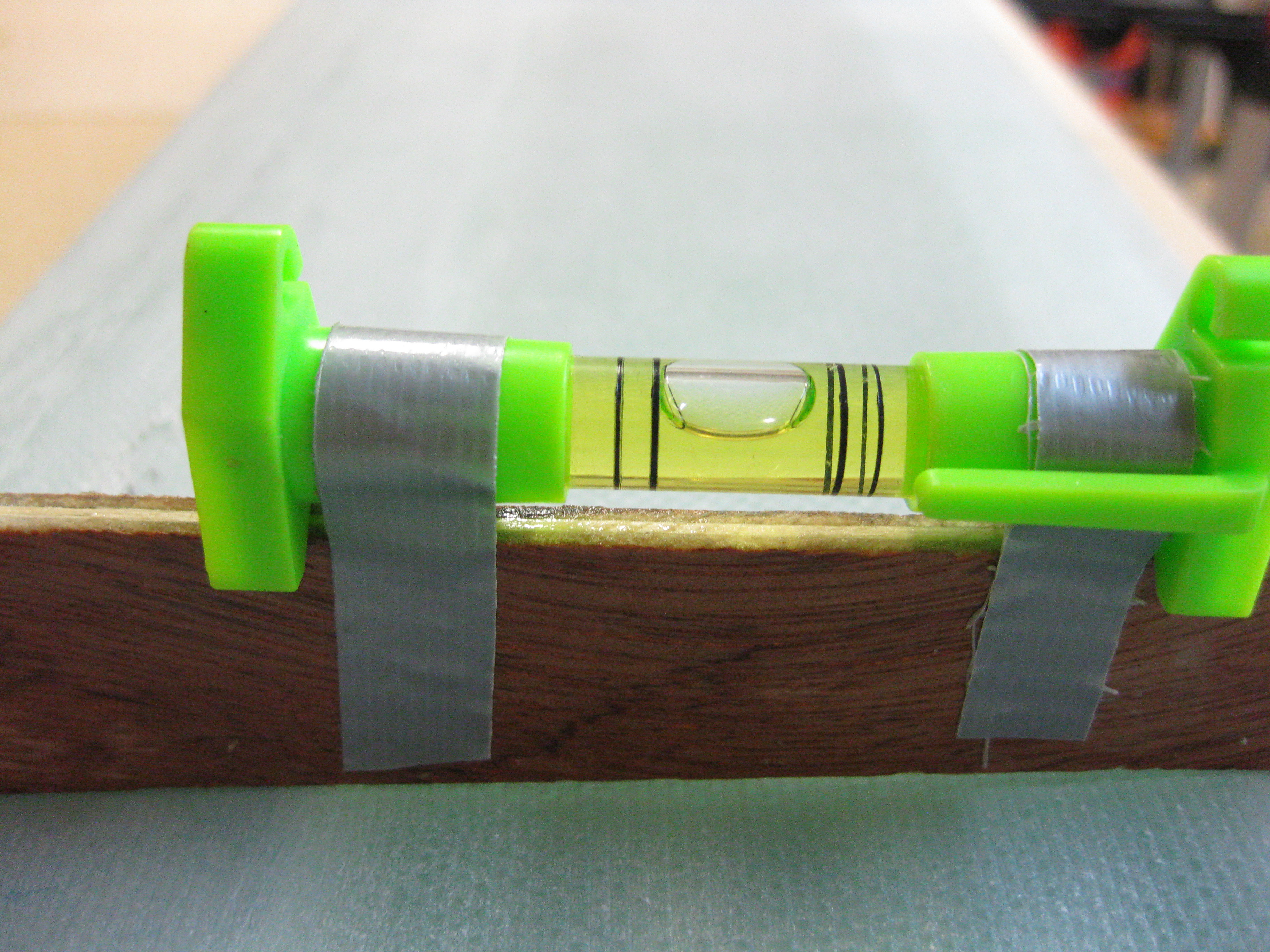
I taped the small level to the top of the sanding block to give me a general idea at all times how the block is angled compared to the table, and in turn the bottom surface of the canard.

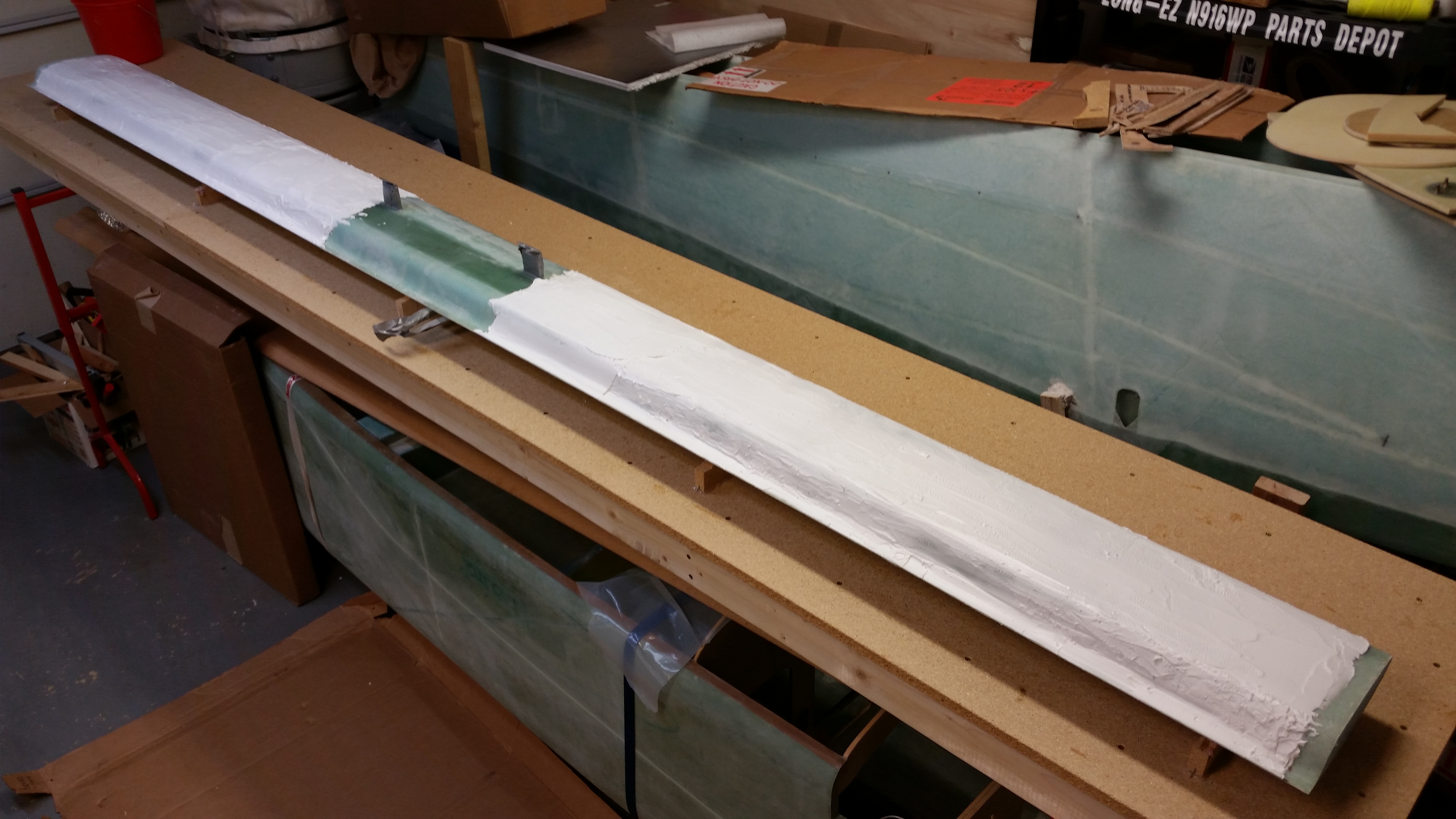
Below is a shot after the first few passes on the lower Left side surface of the canard.
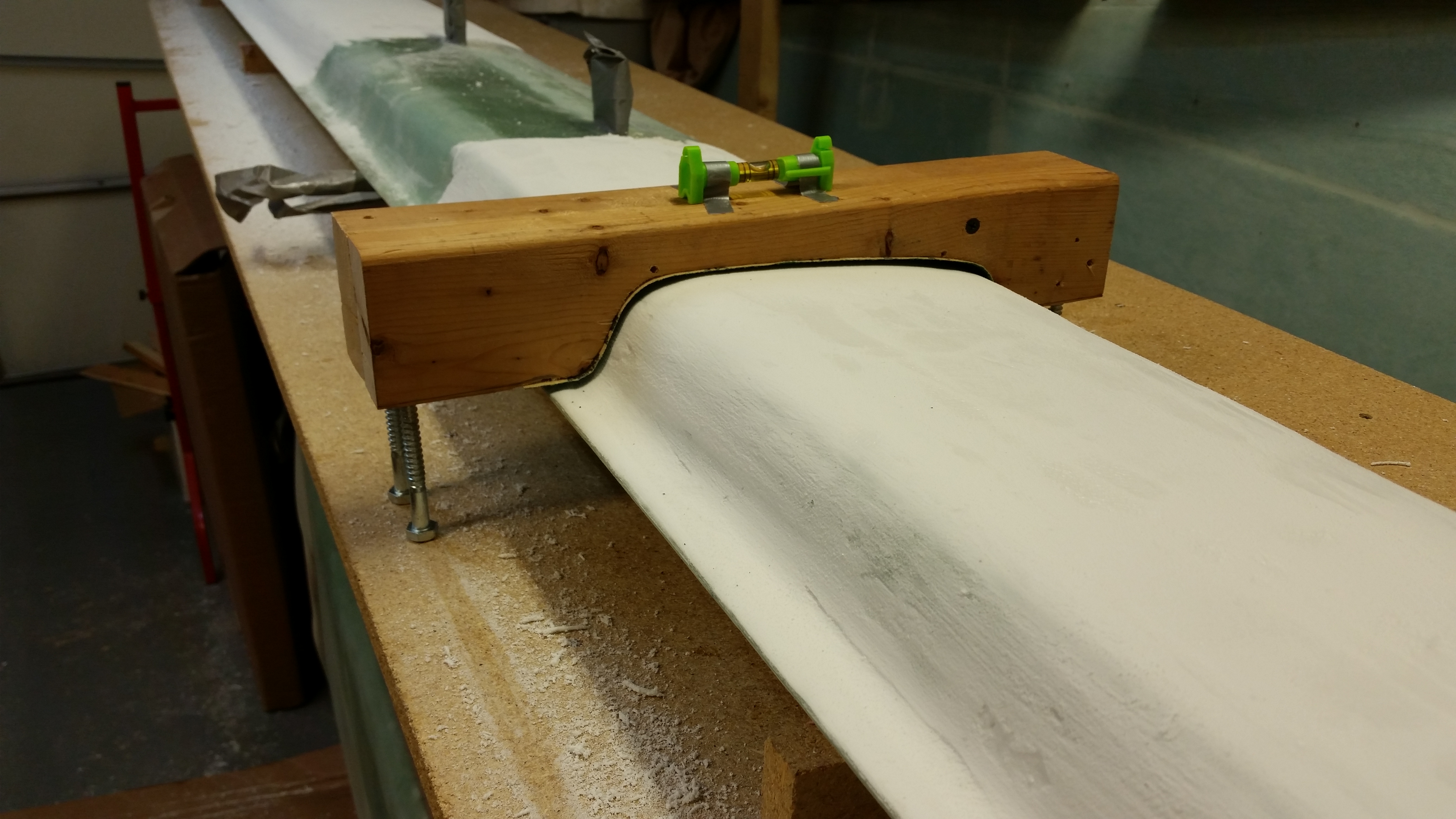
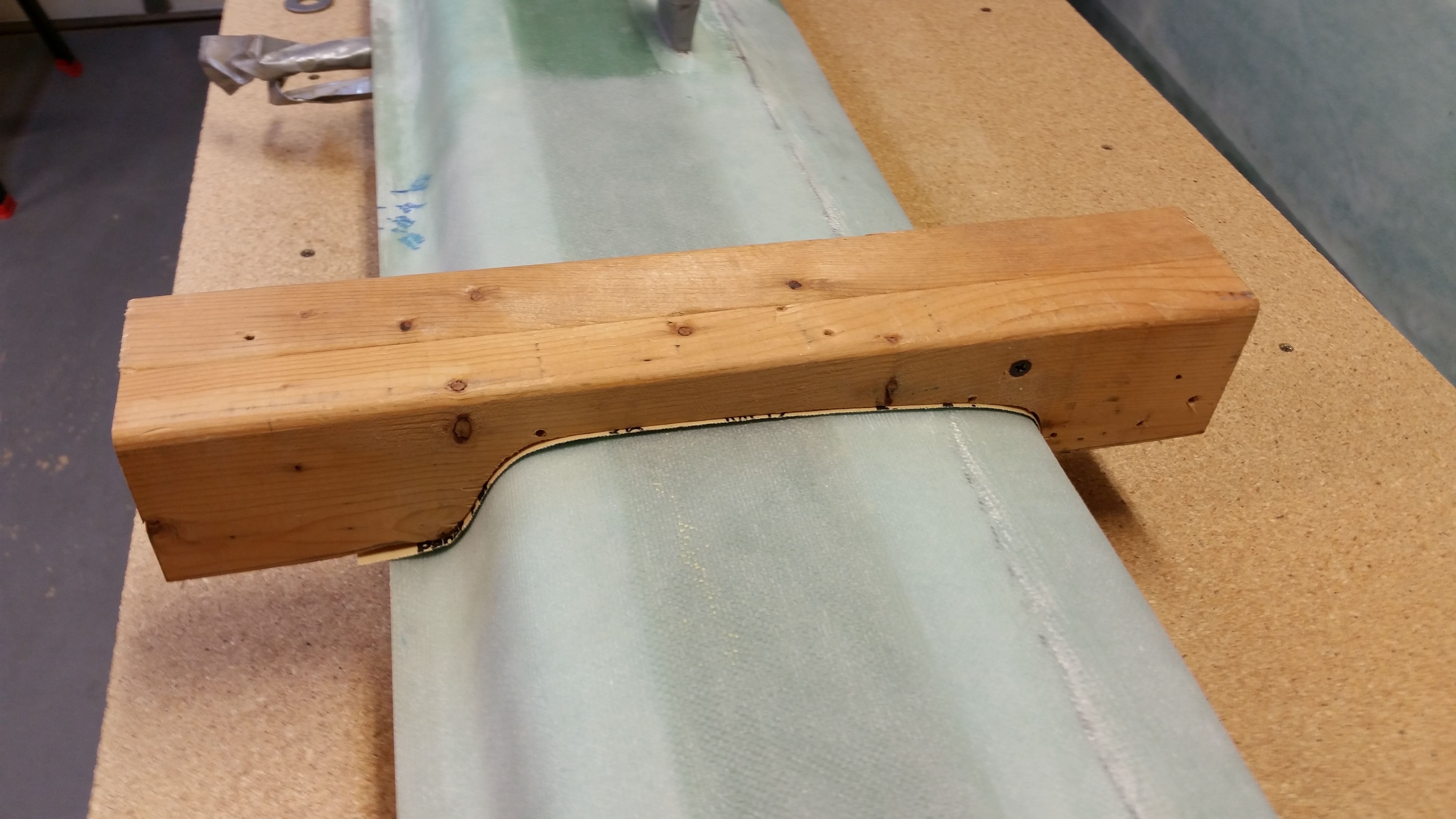
Lower Canard Contour Sanding Block

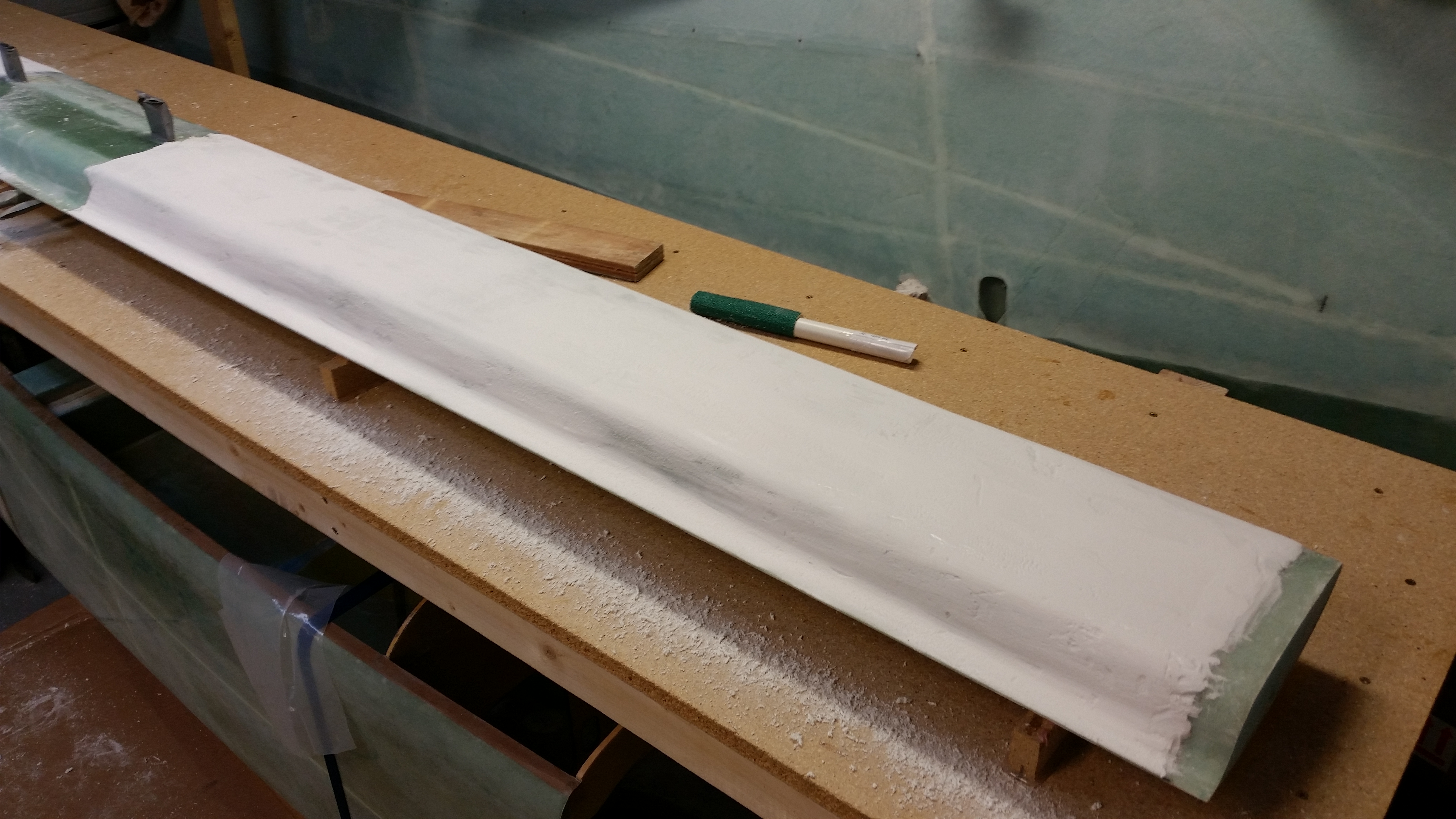
And another shot after multiple, multiple passes and about 4 lowerings of the sanding surface.

Sanding micro - Round 1

I was happy with the progress, but one minor issue I found is with the relatively high build in the fishtail area of the TE as compared to the lower build of micro on the front LE area. This difference in micro thickness resulted in an affect where the natural flow of the contour sanding was resulting in the LE getting more abrasive action initially than the TE.  In other words, I was either fairly close or already down to LE glass up front with still a relatively decent amount of micro to remove in the TE area.  Part of this issue was the good amount of micro build I had on the entire bottom surface of the canard.  I simply have to get through both the bottom surface buildup of micro before the contour sanding block really starts cutting into the micro on the TE’s fishtail trough, thus, alleviating the current unbalanced cutting action of the contour sanding block.
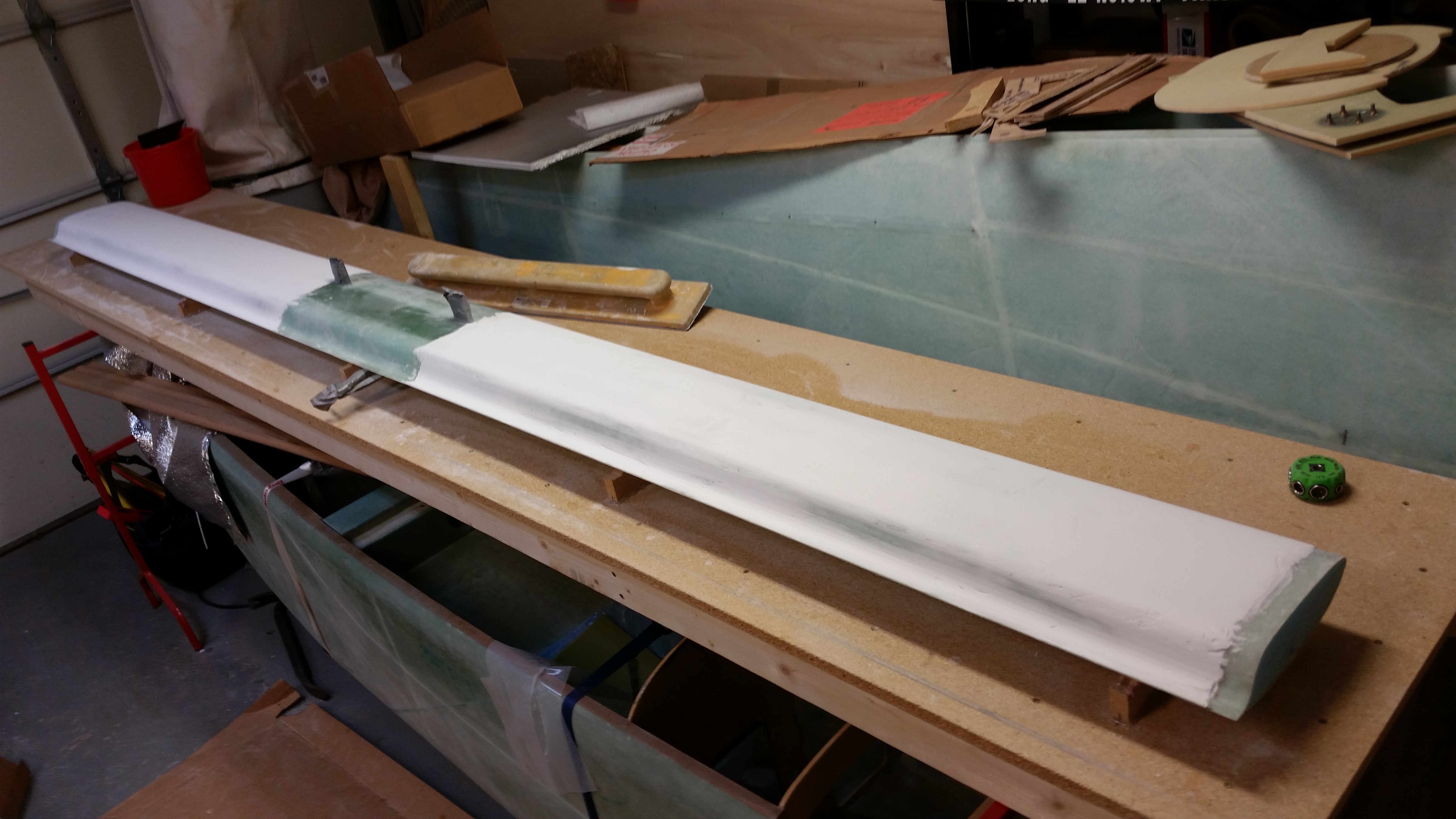
Finishing Lower Canard

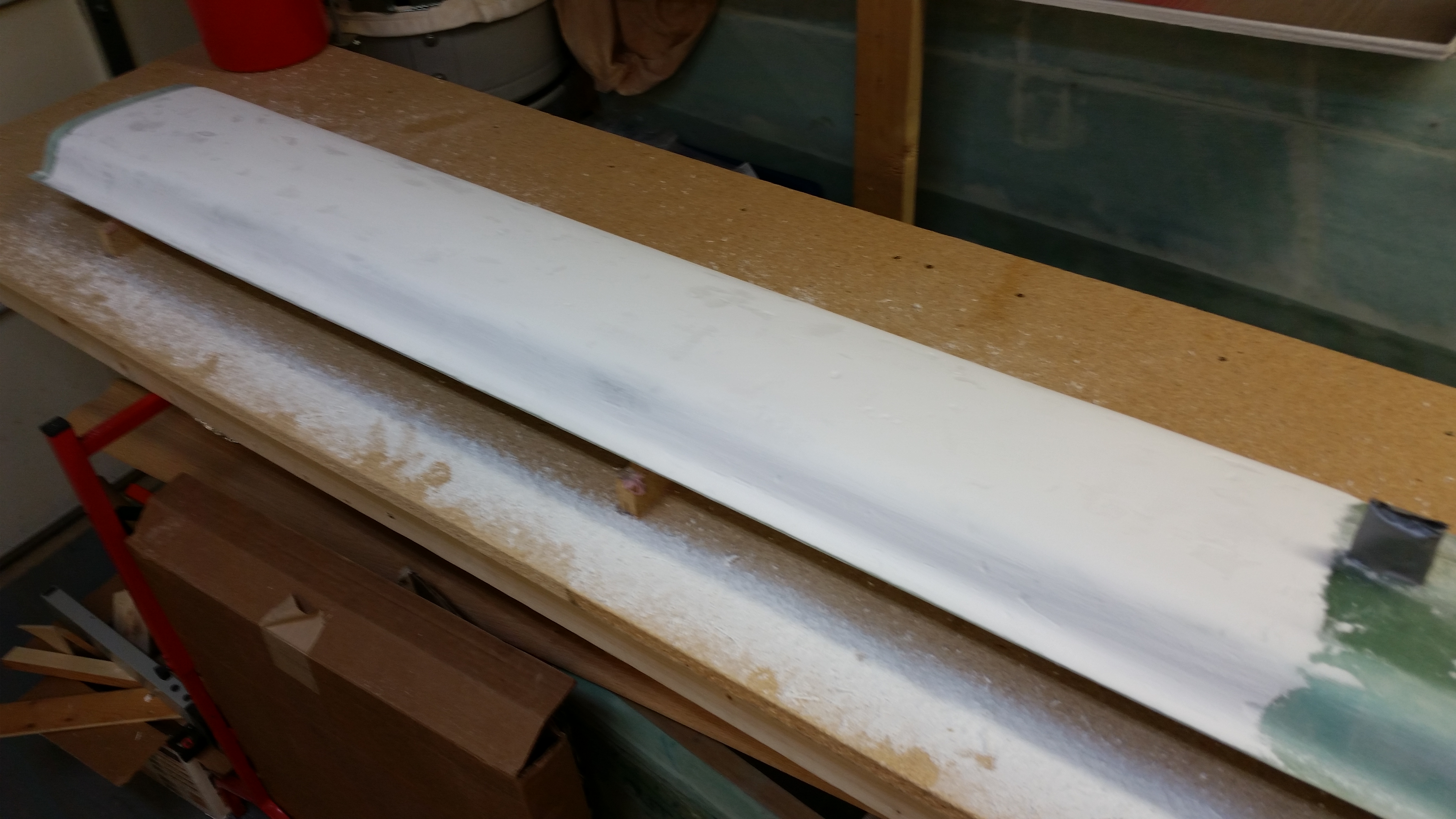
Since I had pretty much killed the first piece of 36 grit sandpaper on my contour sanding block (I should say 3 distinct areas of the paper), I set aside the contour sanding block and decided to call in backup.  I pulled out the mo-jamma rigid 30″ x 4.5″ 3M marine sanding block (also recommended by Wayne Hicks) with 36 grit sandpaper.   I worked each side for about 15 minutes each in the standard 45° to the left, then 45° to the right pattern.

I used some fairly hard pressure and was amazed at how tough that micro is after its cured.  But I could tell by the significant amount of micro powder that I was producing that the long block was doing its job.
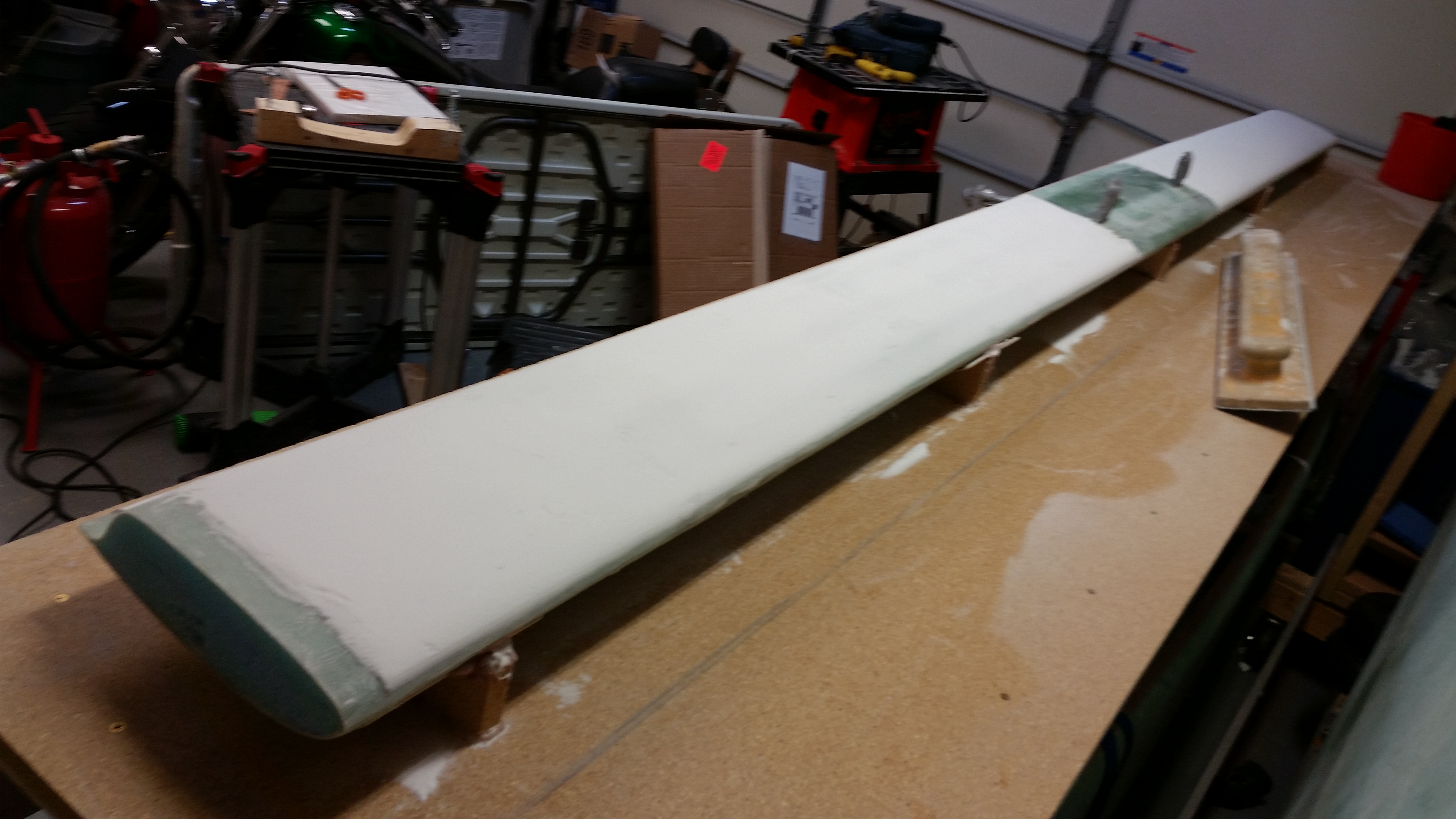
Finishing Lower Canard

All in all I spent about 2.5 hours sanding yesterday, and have at least that much more to do tomorrow to get this thing into the shape I need.  I’ll start with the long block again tomorrow to knock down a fair amount more of the micro build and then switch back to the contour sanding block.
 

Chapter 10 & 25 – Finishing Canard

Today I undertook my first official act of finishing a surface on this Long-EZ.  As I mentioned before, I re-read the notes & material I had on finishing to brush up on this endeavor that apparently seems to be half science and half art.

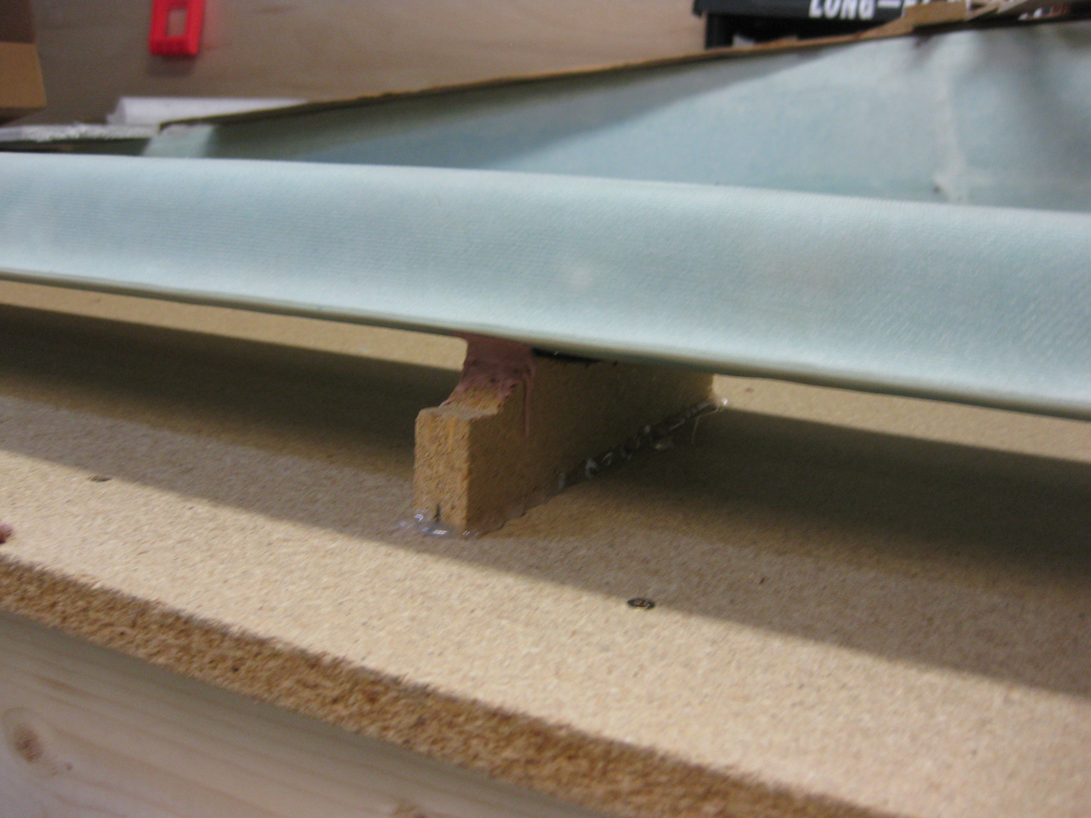
I started out the morning by confirming the side-to-side slant of my workbench so I would know how to position the canard to match the workbench surface.  My first thought was to simply use cargo straps in the center area of the canard, but after playing around with the whole setup I realized that the “K” mounts weren’t entirely even (how I had placed them, and they were now glued to the table… I believe this is in concert with slight differences with the top surface of the canard as well).  This meant that the contacts between the underside (actually the top) of the canard as it lay here was not in perfect contact with the “K” mounts.  When I tightened the tie-down straps on each side of the mounting tabs, I was getting all kinds of weird angles due to the force down on the center of the canard, making the outboard areas seat differently on the “K” mounts.

After playing around with the straps for about 30 minutes, I realized that I had to call “no joy” on this method and resort to something I really didn’t want to use: Bondo.

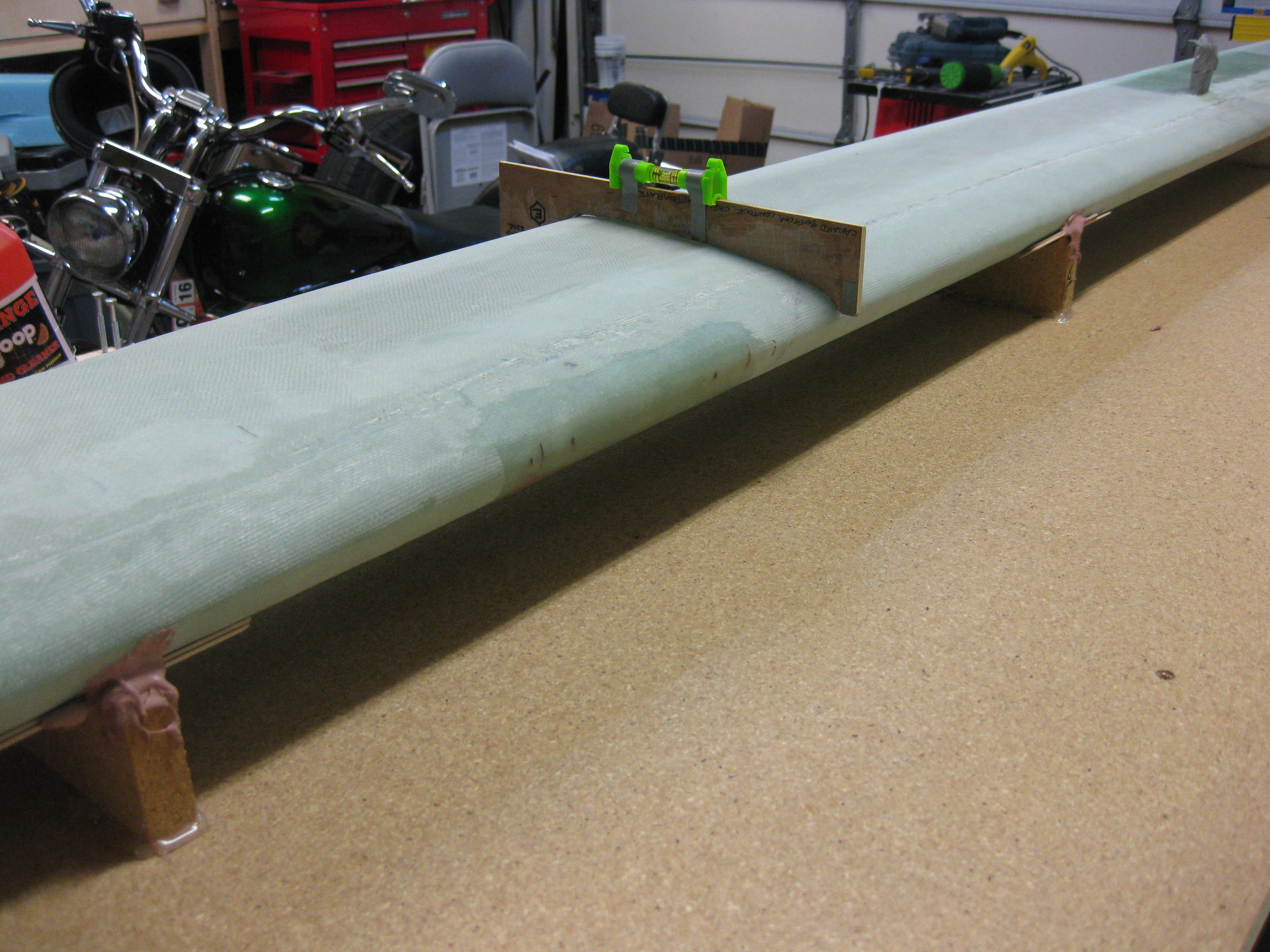
I spent about another 45 minutes working to get the canard to lie naturally on the supports without any stress from the top (technically bottom canard surface) of the canard in this position.  Since the spar cap may be higher on the aft side in one area of the canard and then higher on the forward side 2 feet down the canard, there are a myriad of tiny surface variances that affect how the level attached to the “E” template will read.  I spent a lot of time figuring out where my “normal” areas were that I was getting good readings, then I found the locations that had weird readings for any surface anomalies rearing their ugly head.

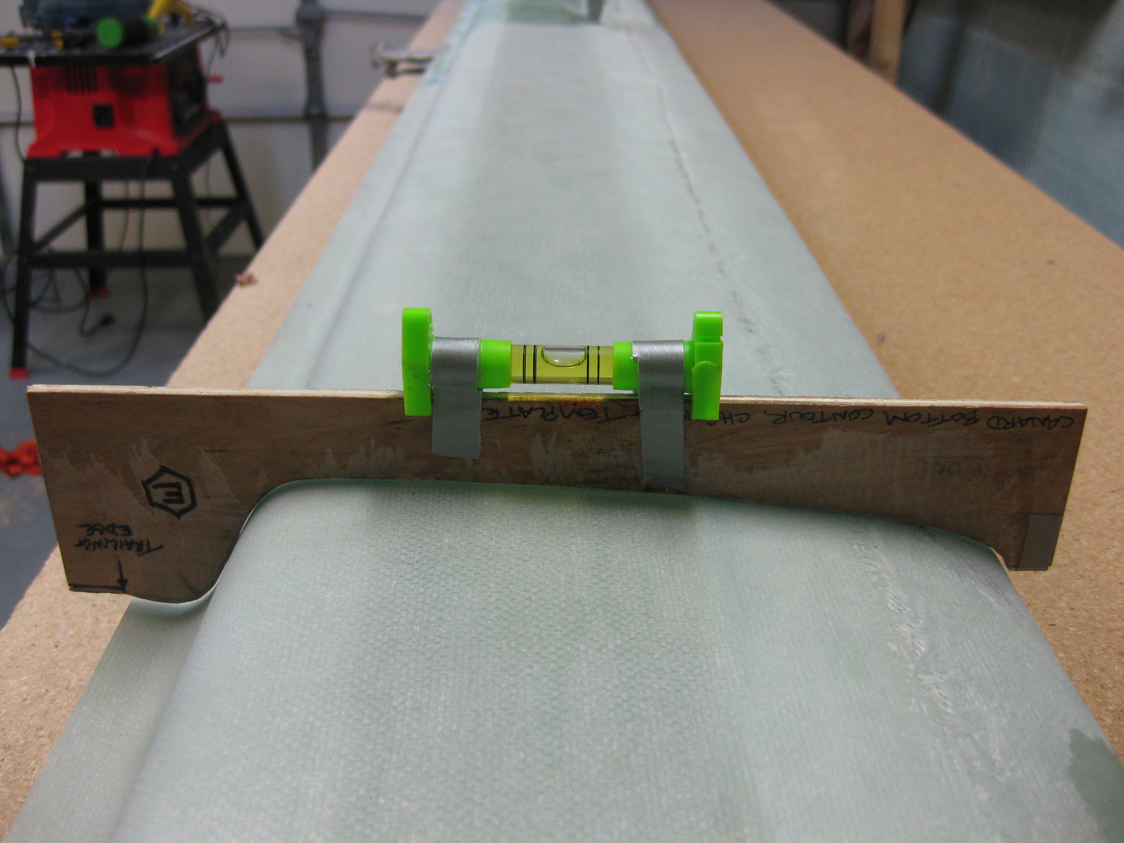
Again, I started with my digital level crossways on the table, as well testing my little bubble level that I taped to the top of the “E” template.

Matching canard incidence with table

Below is the “E” template at the far Right side of the canard, the middle of the canard, and on the Left side of the canard (of course all underside), respectively.   As you can see, the bubble is situated in pretty much the same spot on all of these.

Matching canard incidence with table

Matching canard incidence with table

Matching canard incidence with table

Happy with the position of the canard, I went about the nasty task of Bondo’ing the canard to the “K” mounts.

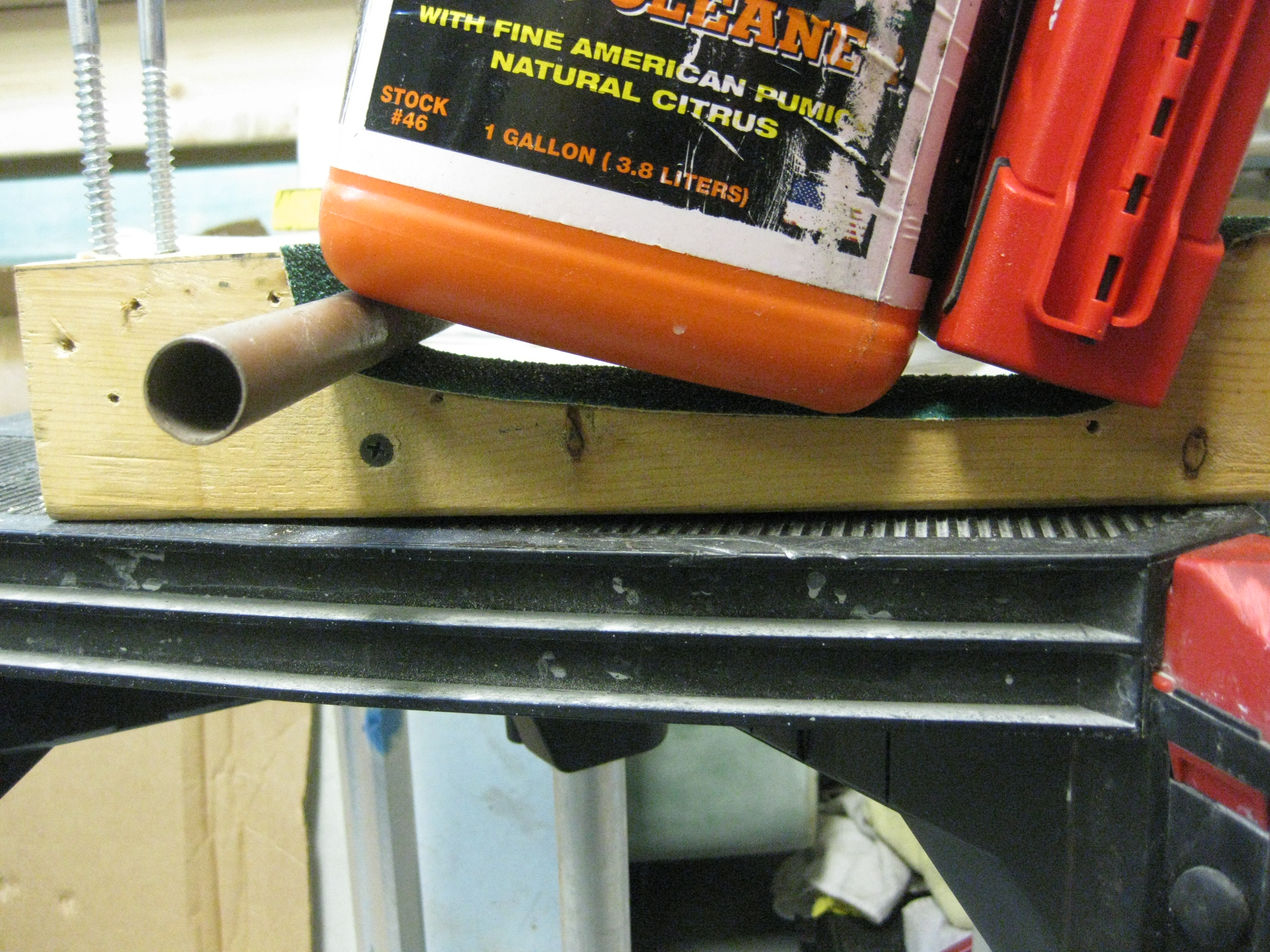
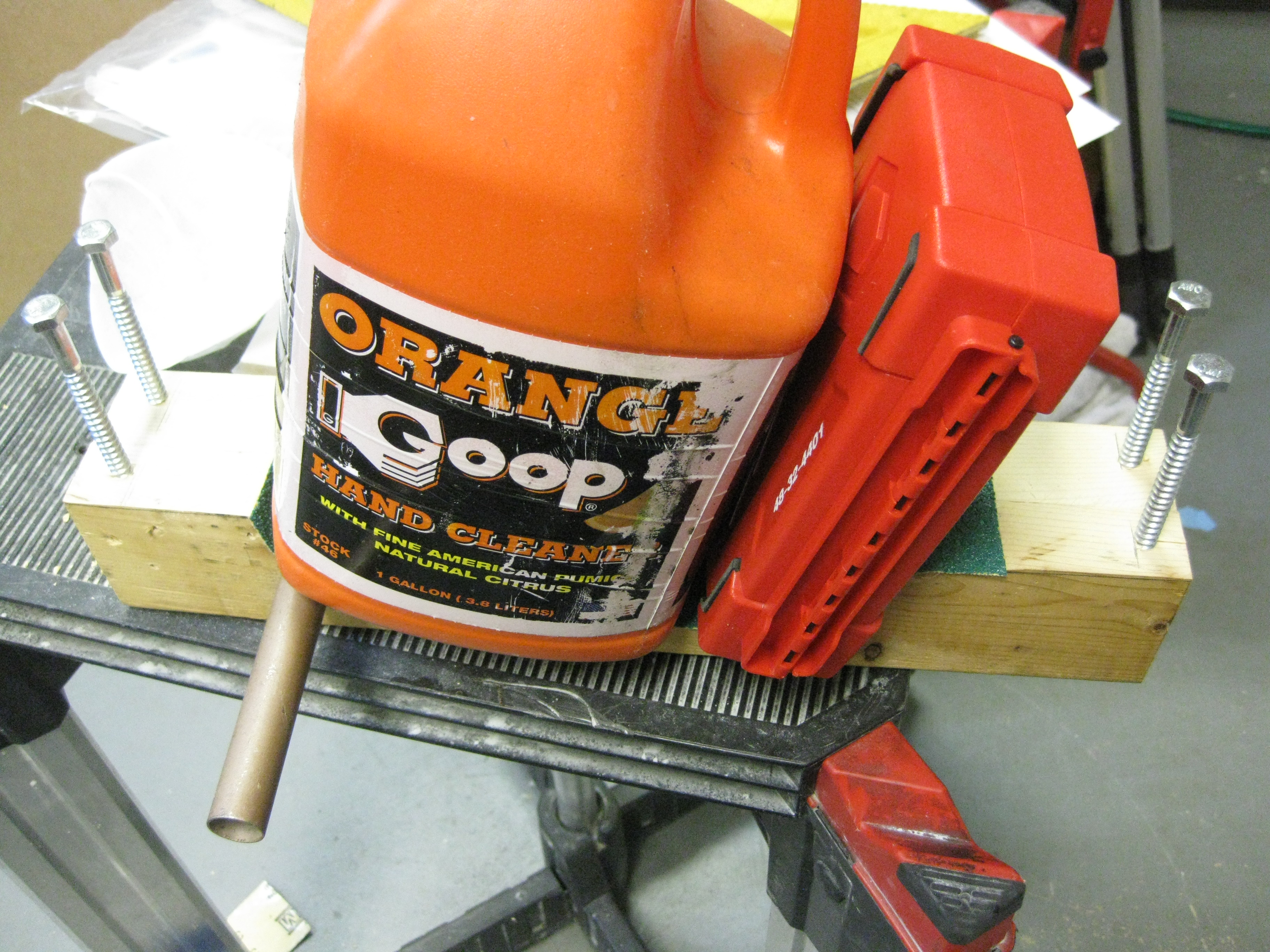
After I was finished with the Bondo and as it cured, I took my Bottom-side Canard Contour Sanding Block outside and shot it with 3M Super 77 spray glue, along with the actual backing of the sticky sandpaper.  Since it takes a bit of time for the spray glue to set up, I went ahead and weighed the sandpaper down to get it to lay correctly in the contoured area.

Weighing down sandpaper while glue dries

Weighing down sandpaper while glue dries

After messing around with getting the sandpaper weighed down, I went back to the canard and spent about 5 minutes double checking that its angle & elevation were correct in relation to the workbench.  Thankfully, it was.

Matching canard incidence with table

And below are some shots of the Bondo holding the canard in its correct position.

Ugh! More Bondo to clean off!

Canard secured to work bench

With the canard nice, snug & secure, I took one last opportunity to sand the LE overlap glass seam and any other overly bright & shiny spots.  After my sanding spree, I vacuumed up the mess and then cleaned the canard surface with an incredible effective cleaning solution: water!

Finishing Underside of Canard

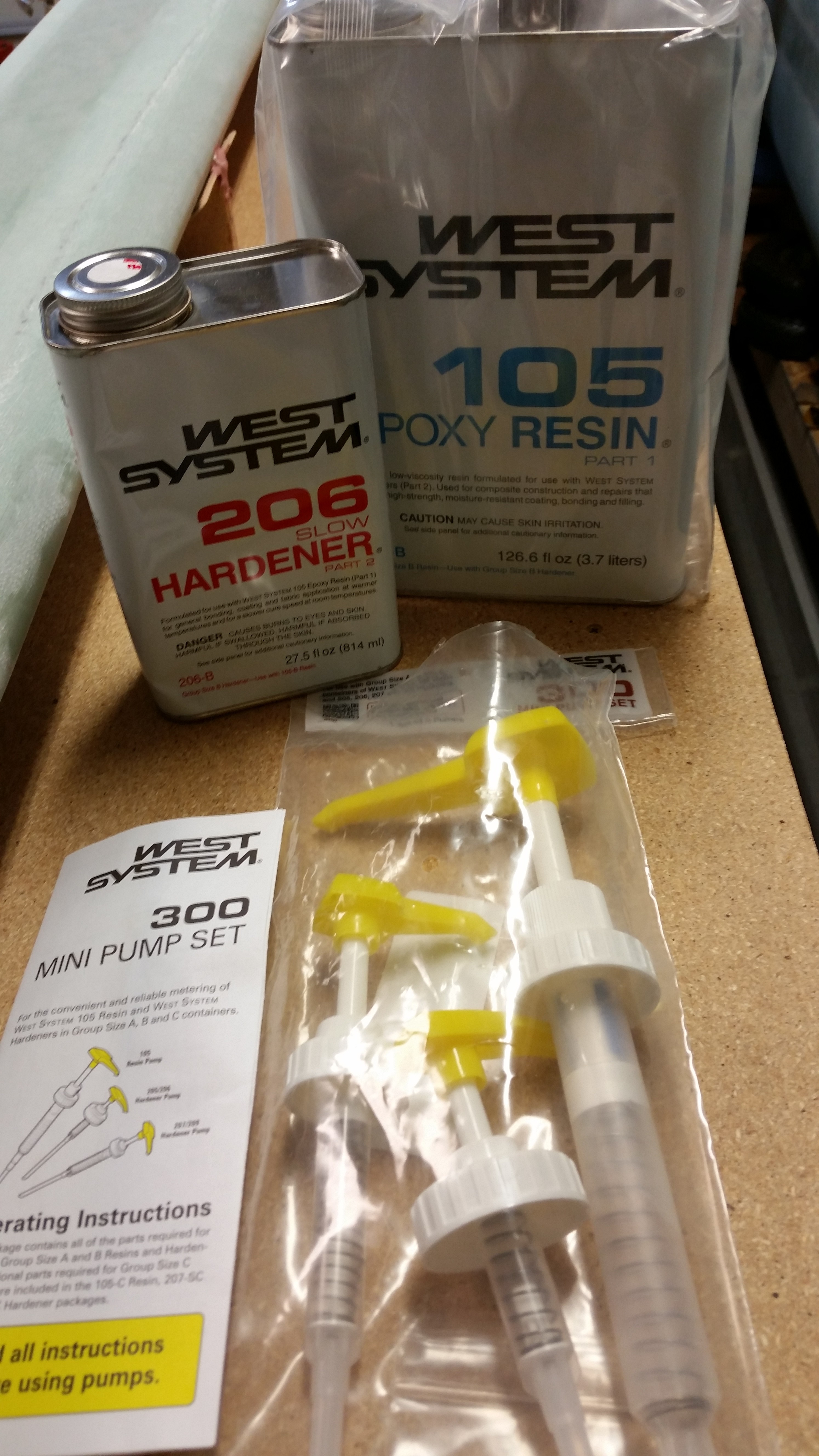
With the canard set to go, I then pulled the West epoxy out of the hot box and gathered up my West epoxy system pump set.  This was going to be pretty fun to use this since the last time I messed around with these pumps was when I took the EAA Composites Course in January 2011.

West Epoxy System

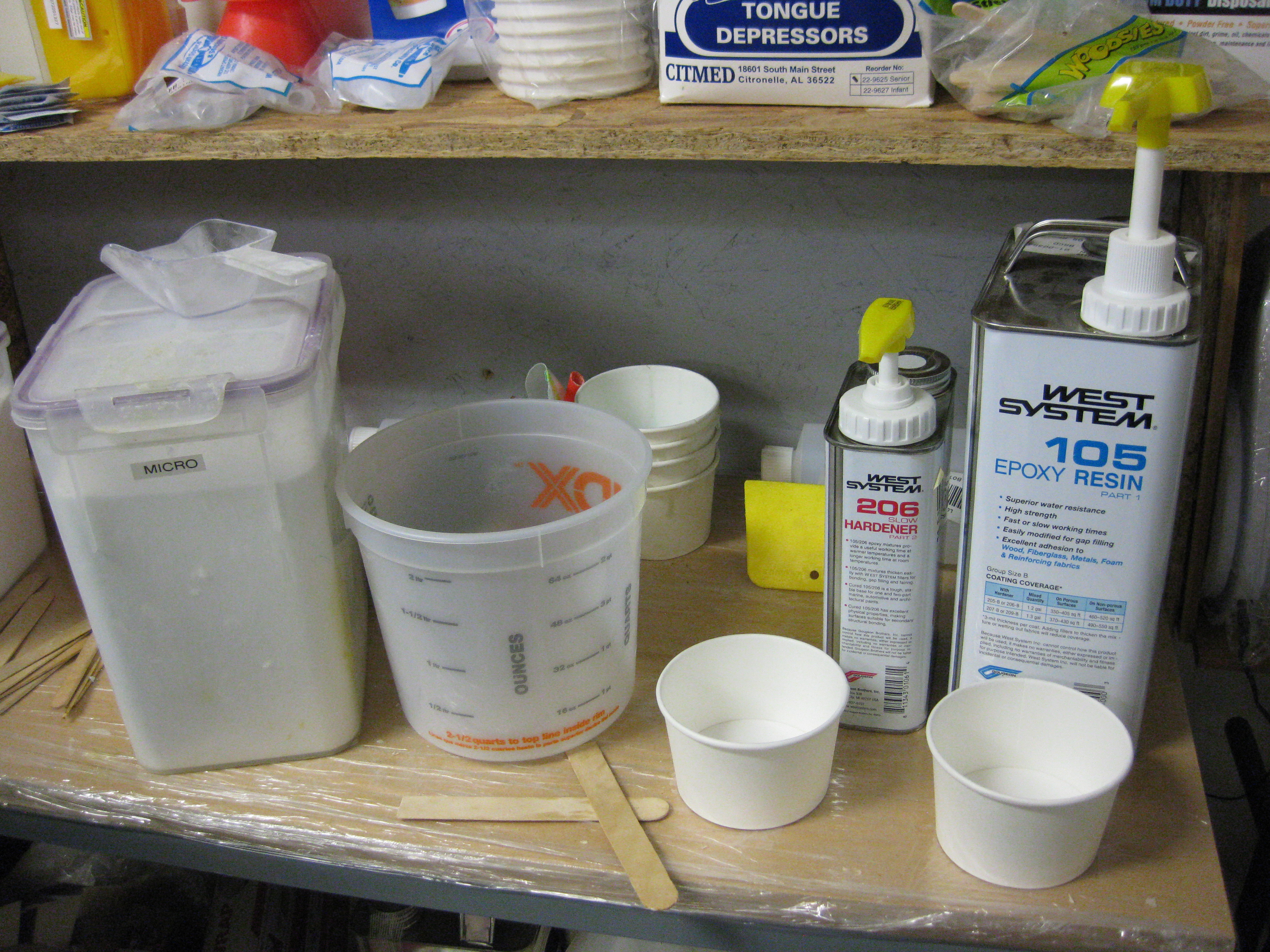
I got my epoxy workstation situated and primed both the epoxy and hardener pumps so that when I pressed on the pump handles I actually got the correct amount of epoxy or hardener per every stroke.

West Finishing Epoxy Setup

Now, I am grateful that my first time out using micro for finishing was on the BOTTOM of the canard, since clearly it’s not as uber critical in shape as the top.  Of course that’s not to say I’m allowing shoddy workmanship, since, yes, I realize that the canard bottom surface & elevators are essentially Fowler Flaps, and clearly the bottom surface shape is important too.

I’ll also admit that in attempting to follow the letter of the micro-finishing law that states that thou shalt use the driest micro possible, after spending 10-15 minutes trying to lay down really dry micro I realized that it was just not working.  I scraped off micro set #1 and it went into the trash.

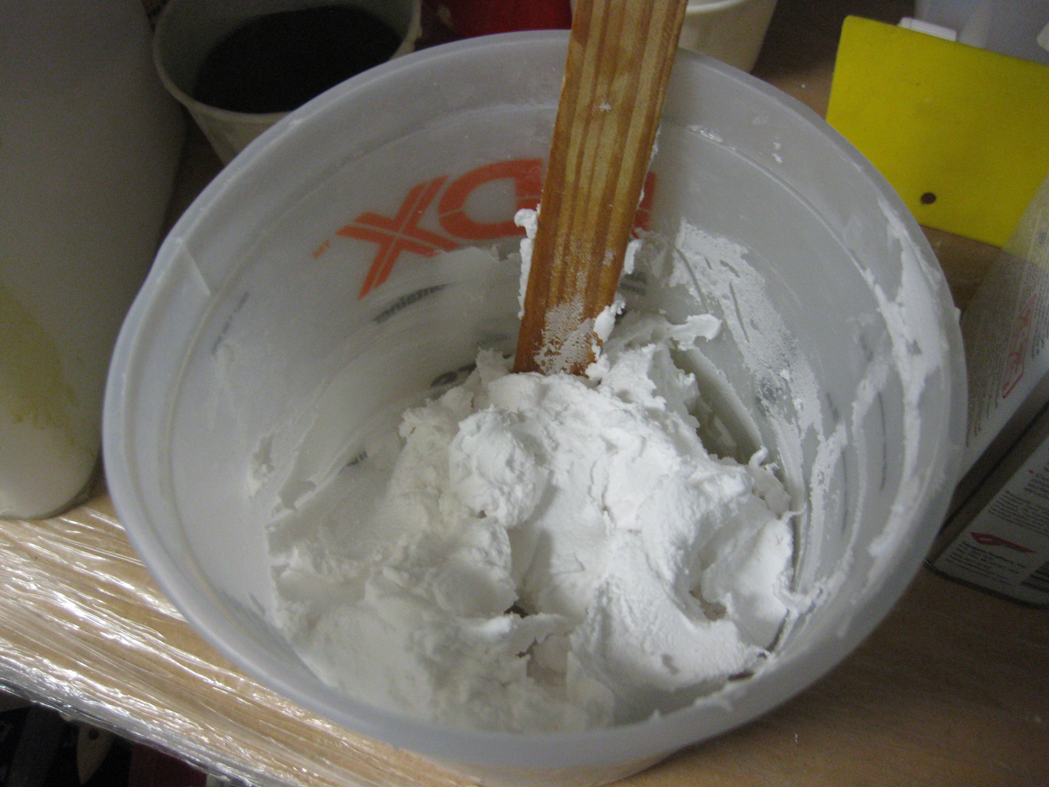
After my on-the-job micro lesson in round one, I simply wimped out and went with only dry micro for the next round.  Amazing what half a cup less of micro in the mix allows one to do!  I may have cheated a hair, but let me tell you, the ability to actually get the stuff to stay on the surface was an awesome feeling . . . and trust me, that doesn’t mean I’m saying it instantly turned easy.  It just went from being an impossible task to an actual possible task, albeit still really challenging (read: PITA!).  I will say though, that with each batch of micro that I laid down I could tell I was getting a better feel for it and my micro-finishing kung fu skills were definitely improving.  Here’s the round 2 stuff:

Micro for finish

And with all that, Voila!  Here is the micro finished underside of the canard, in all it’s glory! (Do you hear something? . . . Are those horns sounding?!)

Initial Micro Finish

After the micro cured for a couple of hours, I followed Wayne Hicks’ advice, who in turn was following Nick Ugolini’s advice, and I started sanding the canard to knock down the high, ugly stuff while the micro was in the “green” stage.  This meant that having only cured for a couple of hours, the West epoxy was still a little rubbery, and thus much more easily sandable than fully cured micro.

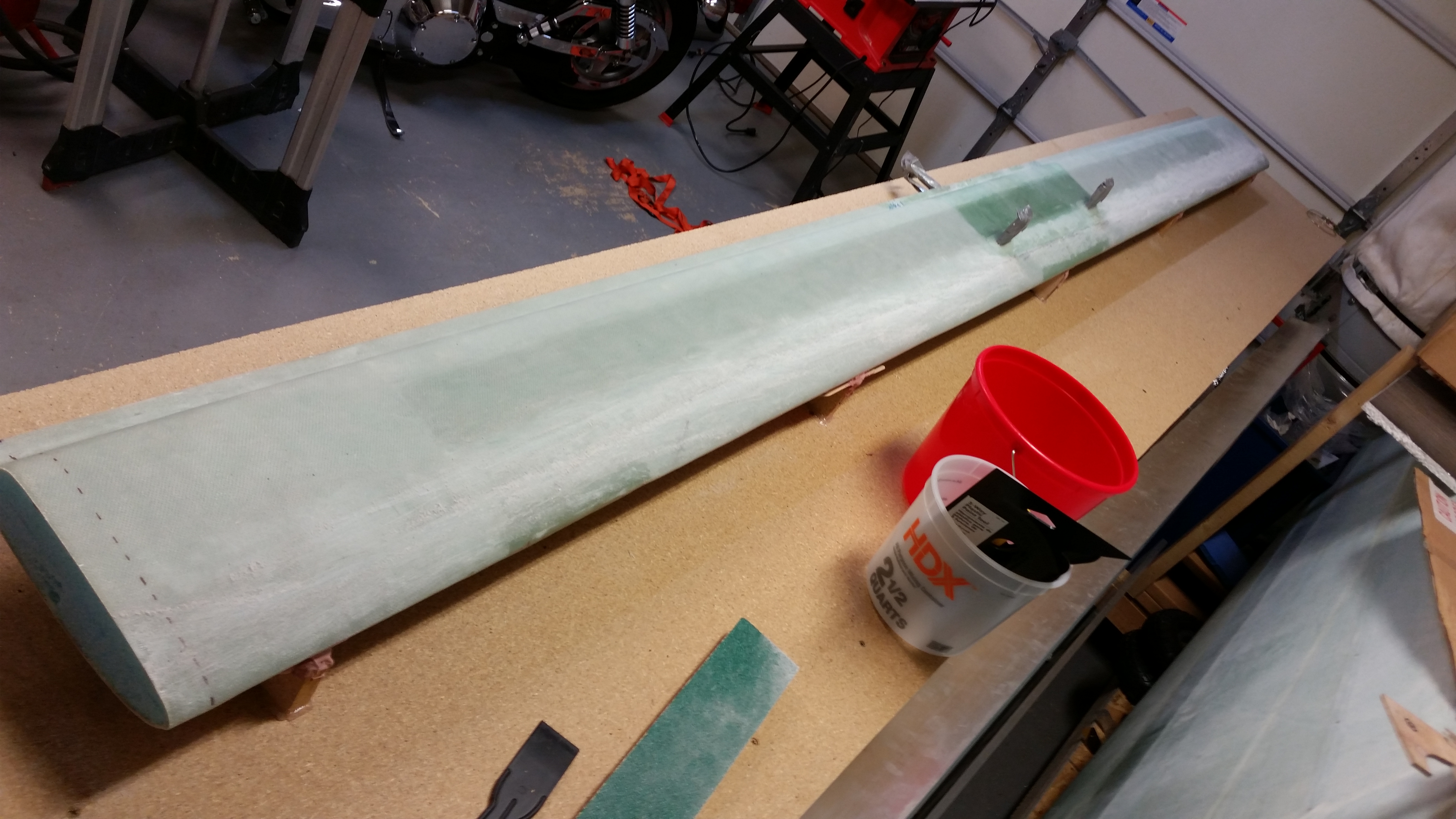
Below is a shot of the underside of the Left side of the canard after I tackled sanding the micro in its “green” stage.

Initial "green" micro sanding (L)

And here’s a shot of the underside of the Right side of the canard after I sanded the micro in its “green” stage.

Initial "green" micro sanding (R)

Tomorrow I’ll sand the micro after its cured completely, using the contour sanding block (of course!).


Chapter 10 – Securing Canard

Early afternoon I went to Home Depot to pick up some supplies to start the micro finish on the bottom of the canard.

Shortly after I returned home, I met future Long-EZ builder, Sohail, and showed him around my shop, and all the various pieces parts of my Long-EZ project.  Of course what ensued was a long conversation on building Long-EZ’s, canards, and airplanes in general.

After Sohail left, I worked on getting the canard mounted upside down on the workbench. Thus, my first order of business was to secure the “K” mounts to the workbench surface.

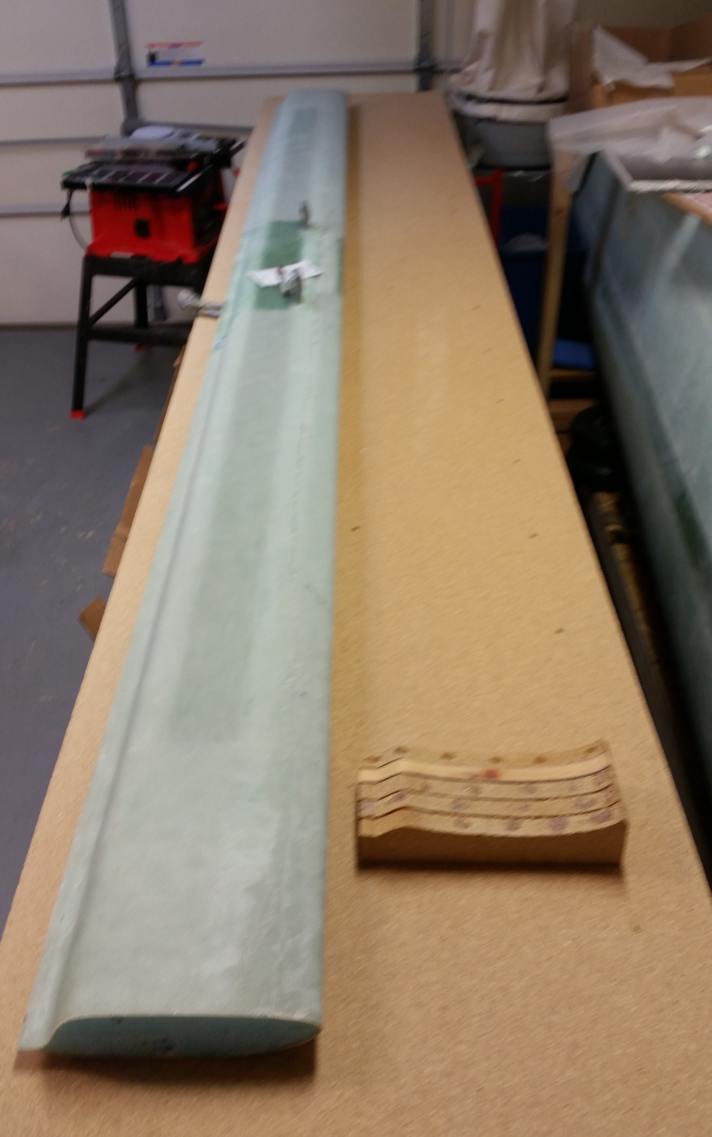
Securing "K" Mounts with Hot Glue

I had thought about either hard-mounting the “K” mounts with screws & maybe some brackets, but I really wanted to minimize the holes in the workbench top.  Plus, all but one of the “K” mounts are made of particle board and I didn’t want to add any stress to them by drilling holes, etc.

Another option was of course bondo, but I didn’t want the mess, the smell or the pain of sanding it off the workbench surface after removing the “K” mounts.  As you can see by the pics, I went the hot glue route.  Hot glue has plenty of strength for the job and it cleans up fairly easily.

After ensuring the “K” mounts were aligned & spaced properly, I hot glued them to the workbench top.

Securing "K" Mounts with Hot Glue

Hopefully tomorrow I’ll get to some micro-finishing!

Chapter 10 – Canard Sanding Block

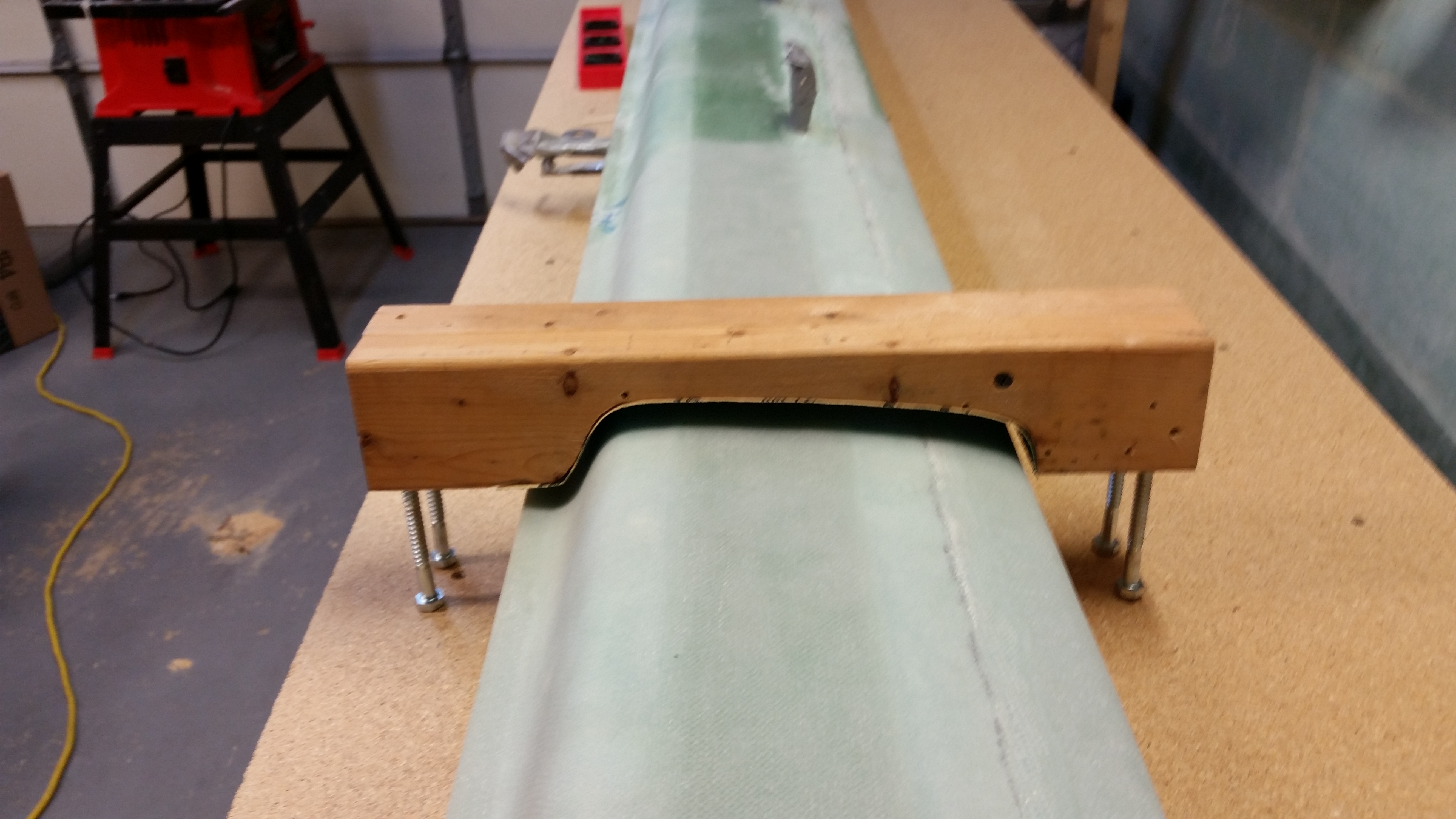
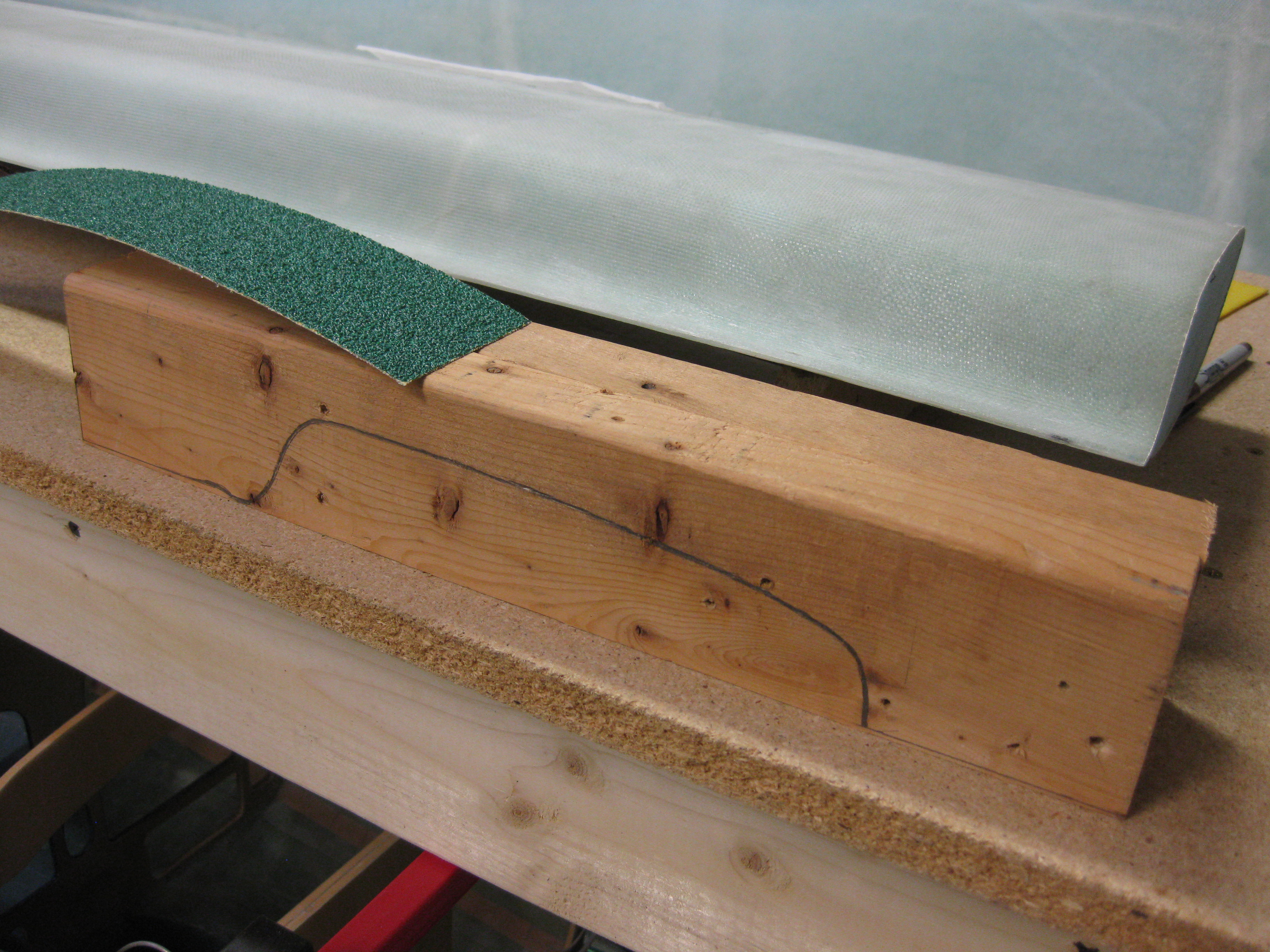
This afternoon was all about making the sanding block for finishing the underside of the canard.  As I described before, this sanding block is nothing more than a 2-3/4″ thick version of the “E” contour template for the Roncz canard.

Yesterday I showed a quick pic of the results of my grabbing a 2×4 out of my scrap pile and tracing the “E” contour template on it.  Once the outline was traced, I used a dull pencil to retrace the line to allow for the actual thickness of the sandpaper once attached to the contour sanding block.  BTW, Wayne Hicks used wider sandpaper than I will be using, but since all my 4″ wide sandpaper is attached via velcro, and my narrower 2-3/4″ sandpaper strips are attached via peel ‘n stick, I figured I would go with the cheaper/narrower peel ‘n stick to start out.  If need be, I’ll change this later on.
Again, yesterday I cut two pieces of a scrap 2×4 to length, and then ripped one of them lengthwise to get the correct width, once the two 2×4’s are joined, to match the sandpaper width.

Today I clamped the 2×4 pieces to my “new” table saw as a work bench and used my jig saw to cut the contour profile.  [SIDE NOTE: A friend of mine called me up & asked me if I wanted this table saw as she was getting rid of it because sadly her dad passed away.  I was wanting a cheaper table saw to use to rip the metal engine mount extrusions since I was really not comfortable doing this on my nicer table saw.  I tested this table saw on these 2×4’s, and so far it works like a champ.]

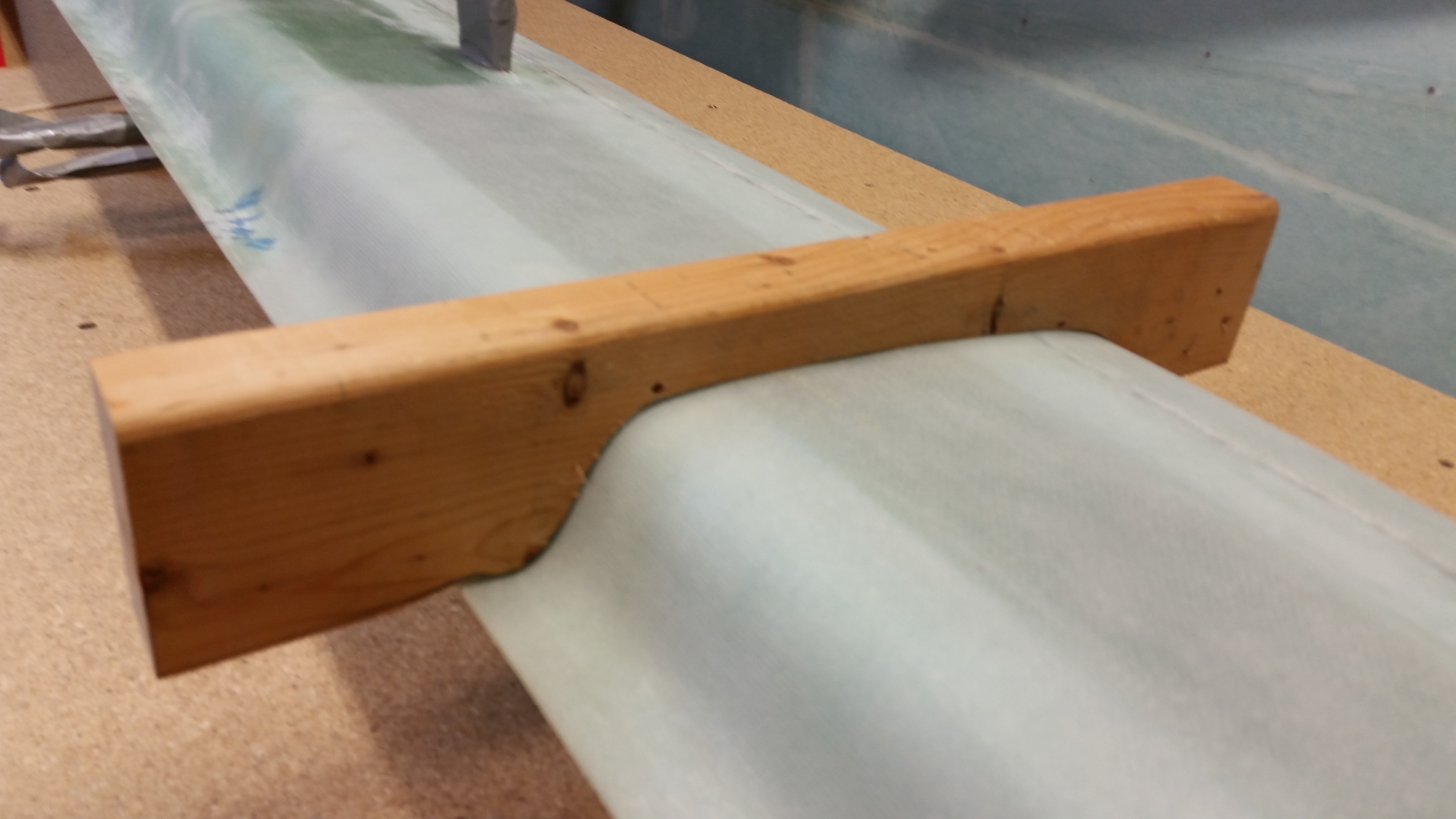
Canard Bottom Contour Sanding Block

Canard Bottom Contour Sanding Block

Here’s the result on 2×4 piece #1:

Canard Bottom Contour Sanding Block

I then transferred the outline of the first (narrower) 2×4 piece to the second 2×4.

Canard Bottom Contour Sanding Block

After the profile shape was cut into 2×4 #2 I then clamped the two sides and screwed them together.  I then cut and attached a piece of sandpaper to the contour of the sanding block.  With the shop at about 70 deg F, I noted the sandpaper was having trouble sticking to the more curvy parts of the contour.  I used the heat gun to warm up the sandpaper’s adhesive backing a little, but even after that I’ve come to the conclusion that I will probably have to use 3M 77 adhesive spray to really get it to stick.

Hmm, maybe a good argument for using the velcro-backed sandpaper?

Canard Bottom Contour Sanding Block

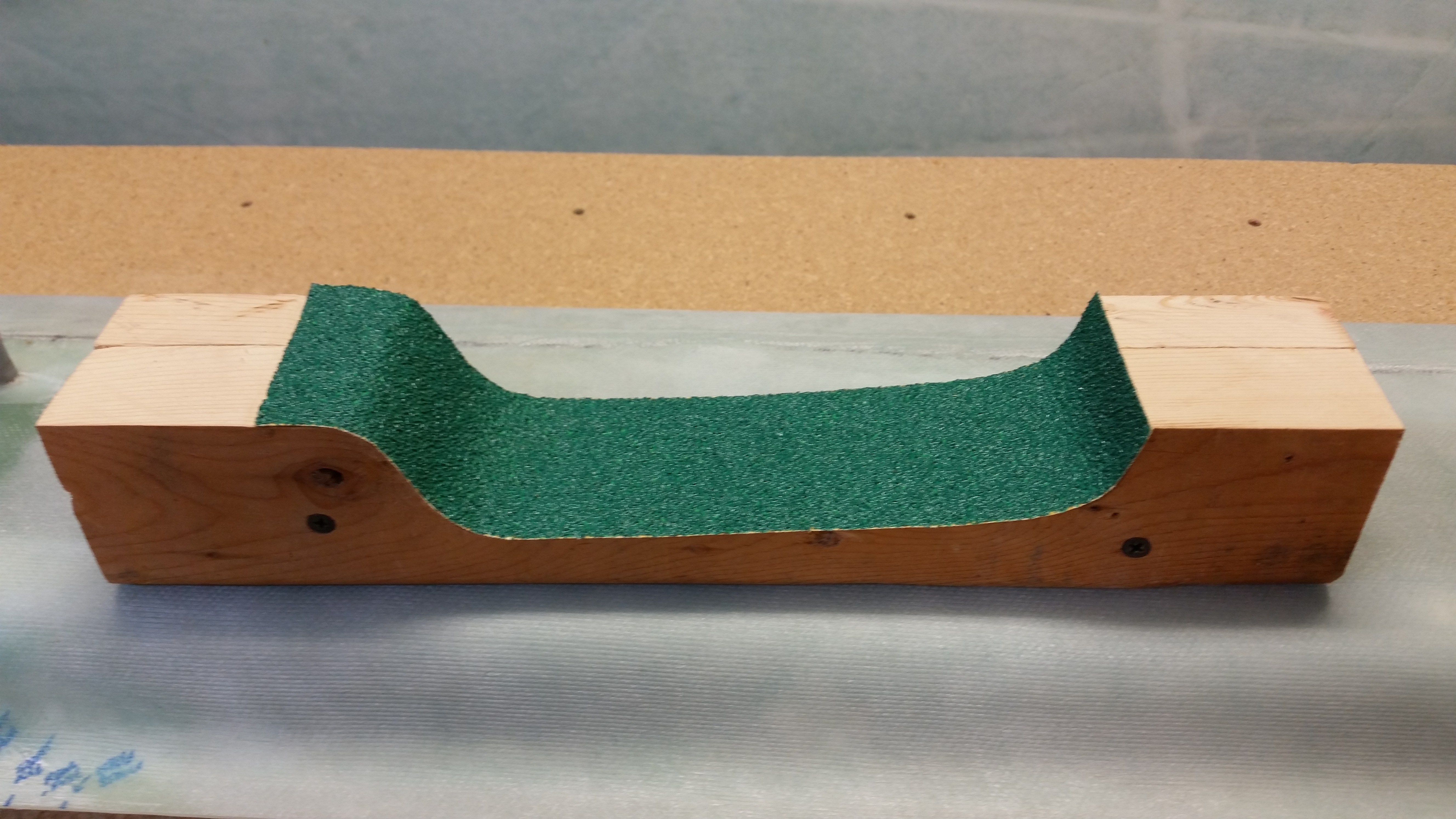
Here’s a shot of the finished product sans “legs”.

Canard Bottom Contour Sanding Block

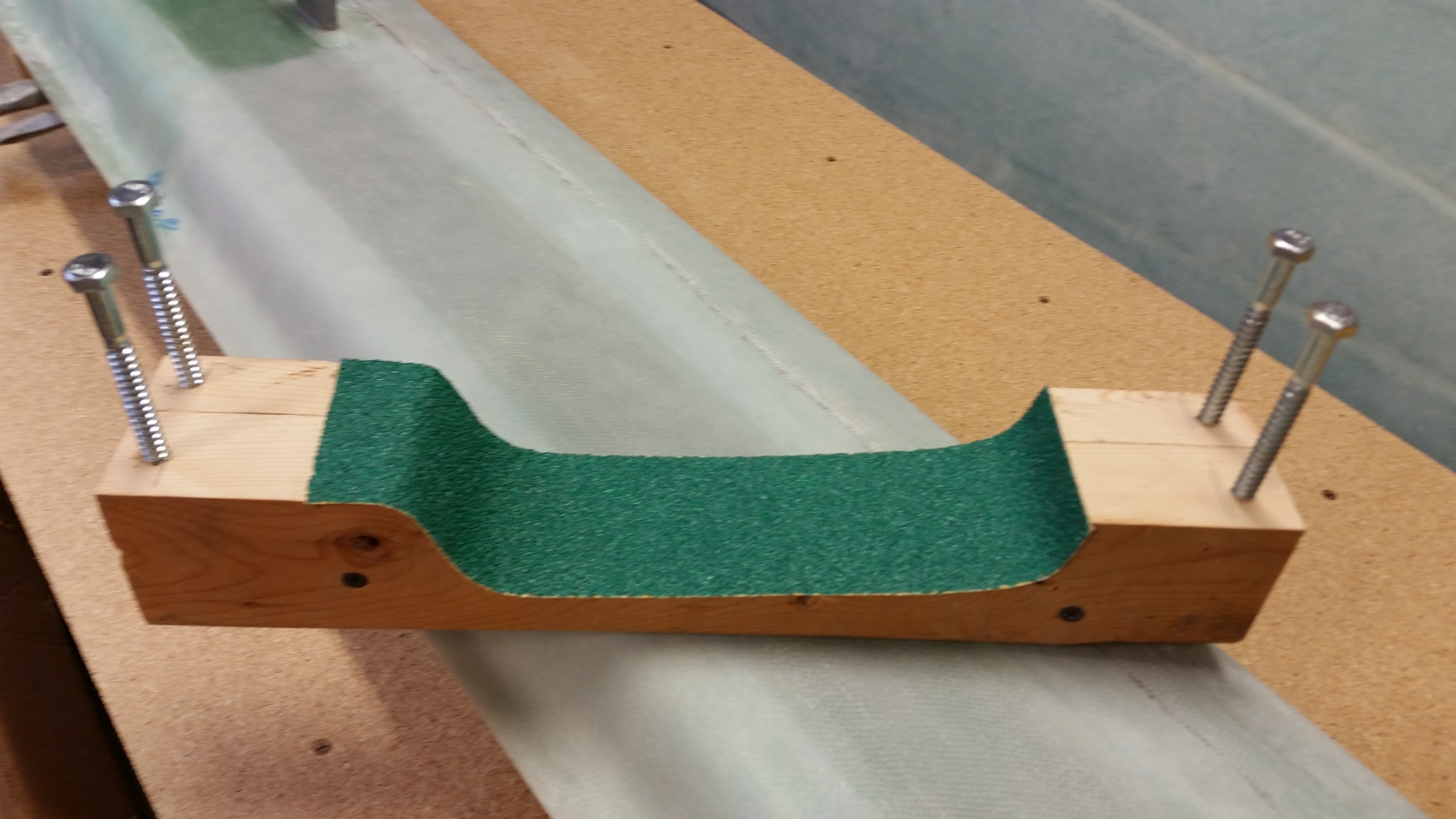
To give this project some legs (yuk, yuk), I drilled a pilot hole in each corner and screwed in a 5/16″ lag screw (I think… don’t quote me on actual size since they were merely sitting there conveniently in my tool bin).  Each lag screw is 3-1/2″ long which will be good for the starting height I’ll need once the canard is mounted.

Canard Bottom Contour Sanding Block

And here’s a quick shot of the finished contour profile sanding block for the underside of the Roncz canard.  Tomorrow, I plan on hard mounting the canard to the table and “K” mounting blocks and then getting to work on finishing the bottom of the canard.

Canard Bottom Contour Sanding Block

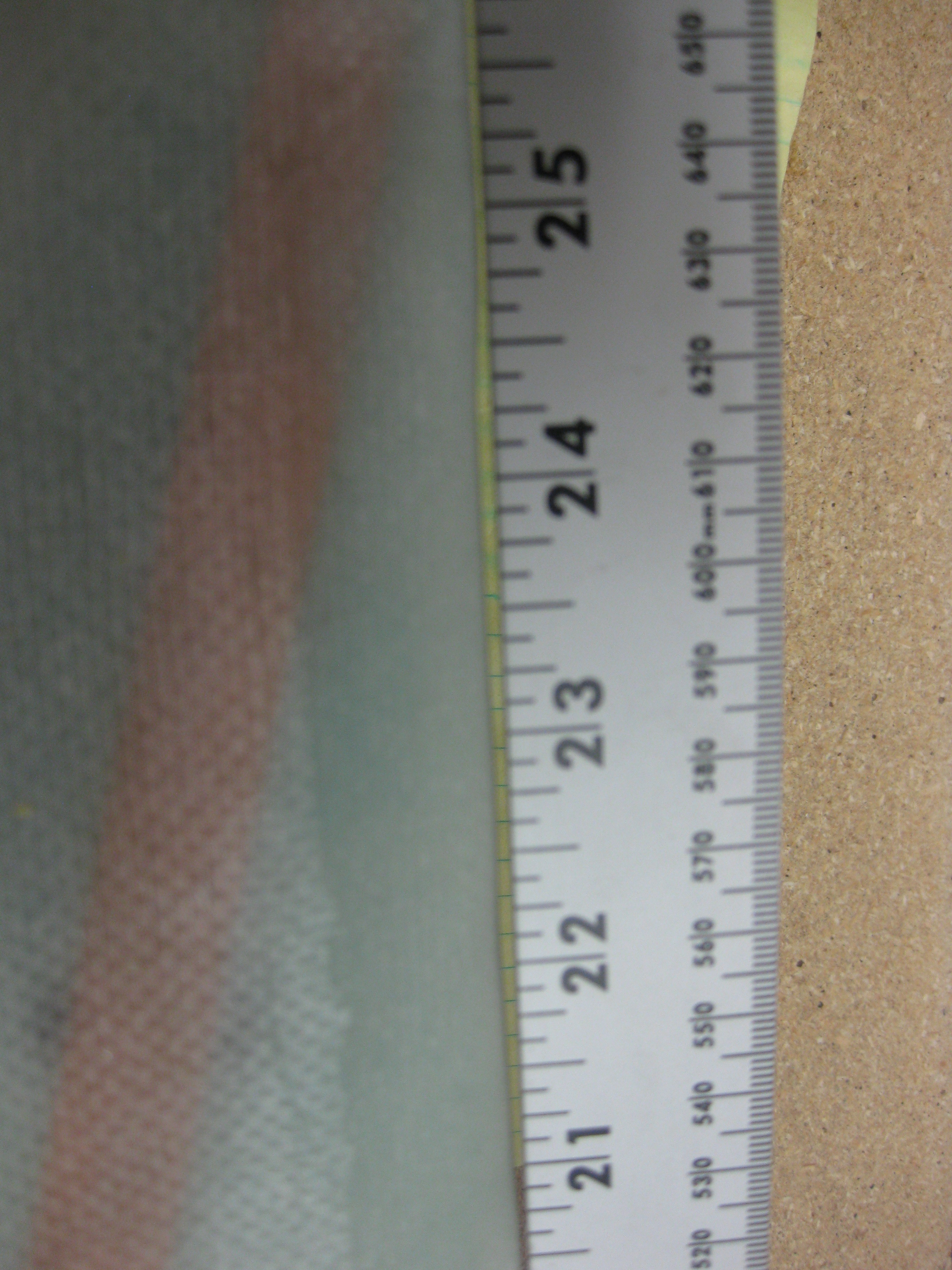
In prep for finishing the bottom of the canard, I marked the canard about 1.2″ inboard of each end to show me the point where I need to stop the micro finish on the lower canard surface.  The reason for this of course is that the Roncz canard swoosh tips require 1″ of glass overlap onto the canard ensure that they’re solidly attached.

Finish-to line on canard end

Ahhh, so tomorrow the games begin in earnest!


Chapter 10 – Canard finishing

Yesterday and today I’ve been pouring over my project to-do lists, plans and tasks in order to get back on track with the build.  After spending hours re-covering specific steps in the Long-EZ Plans Chapter 10, the Roncz canard plans, and the Cozy Girrrls instructions on their elevator actuators, I then went back over my notes on finishing the canard with micro, sanding techniques (mainly Wayne Hicks’ methods), etc.

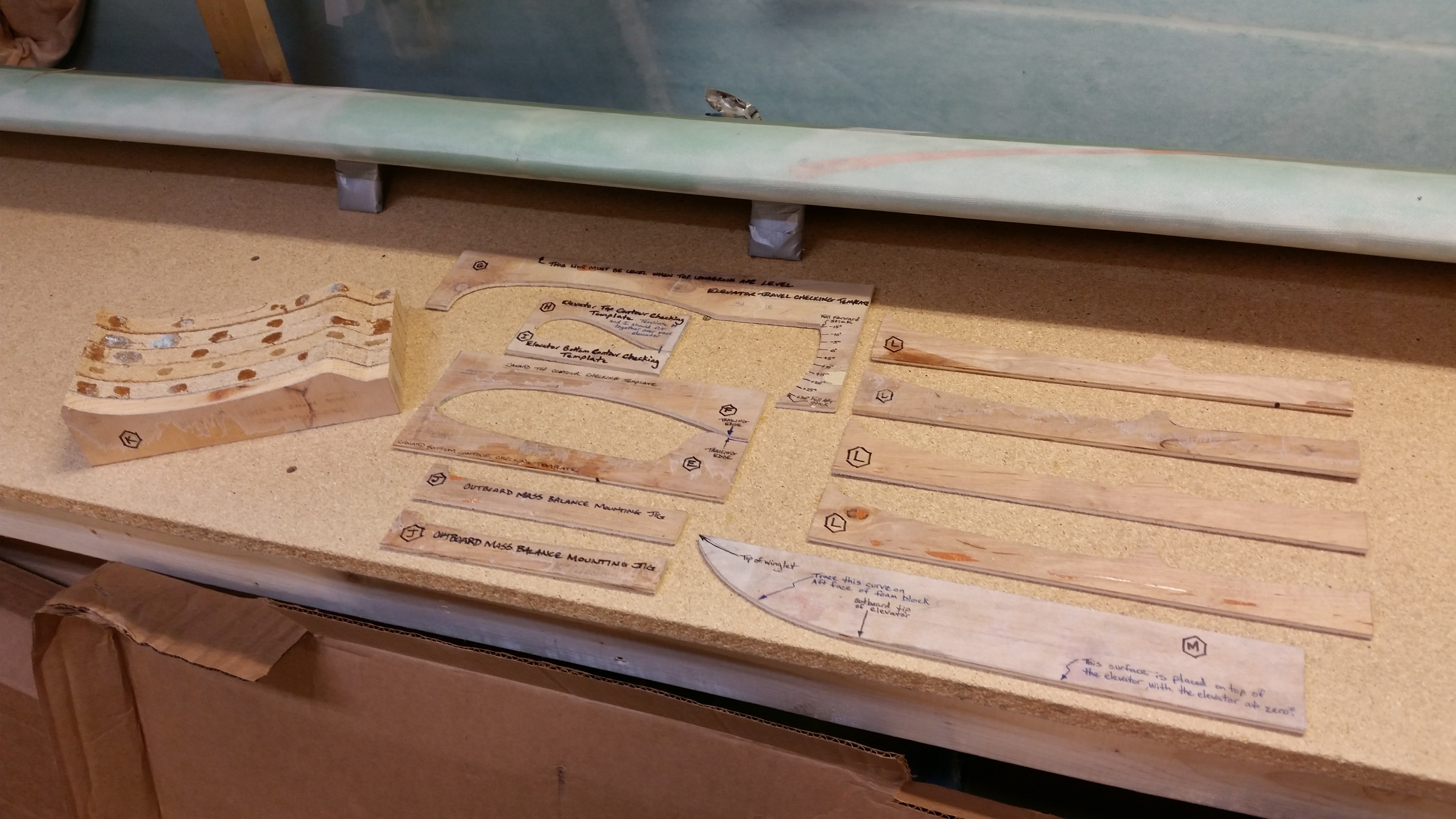
My first order of business, after cleaning & organizing the workshop a bit, was to find all the templates related to the canard and elevators.  That took maybe 5 min since luckily I had the box in which they resided in sitting on the work bench.  Hey, sometimes I guess I am a little proactive!

Chap 10 & 11 Templates

My next task was to clean all the goop off the “K” canard mounts to allow them to be reused while finishing both sides of the canard.  I spent about 15 with a razor knife cleaning up the crud to allow for a fresh clean canard mounting.

Prepping Canard

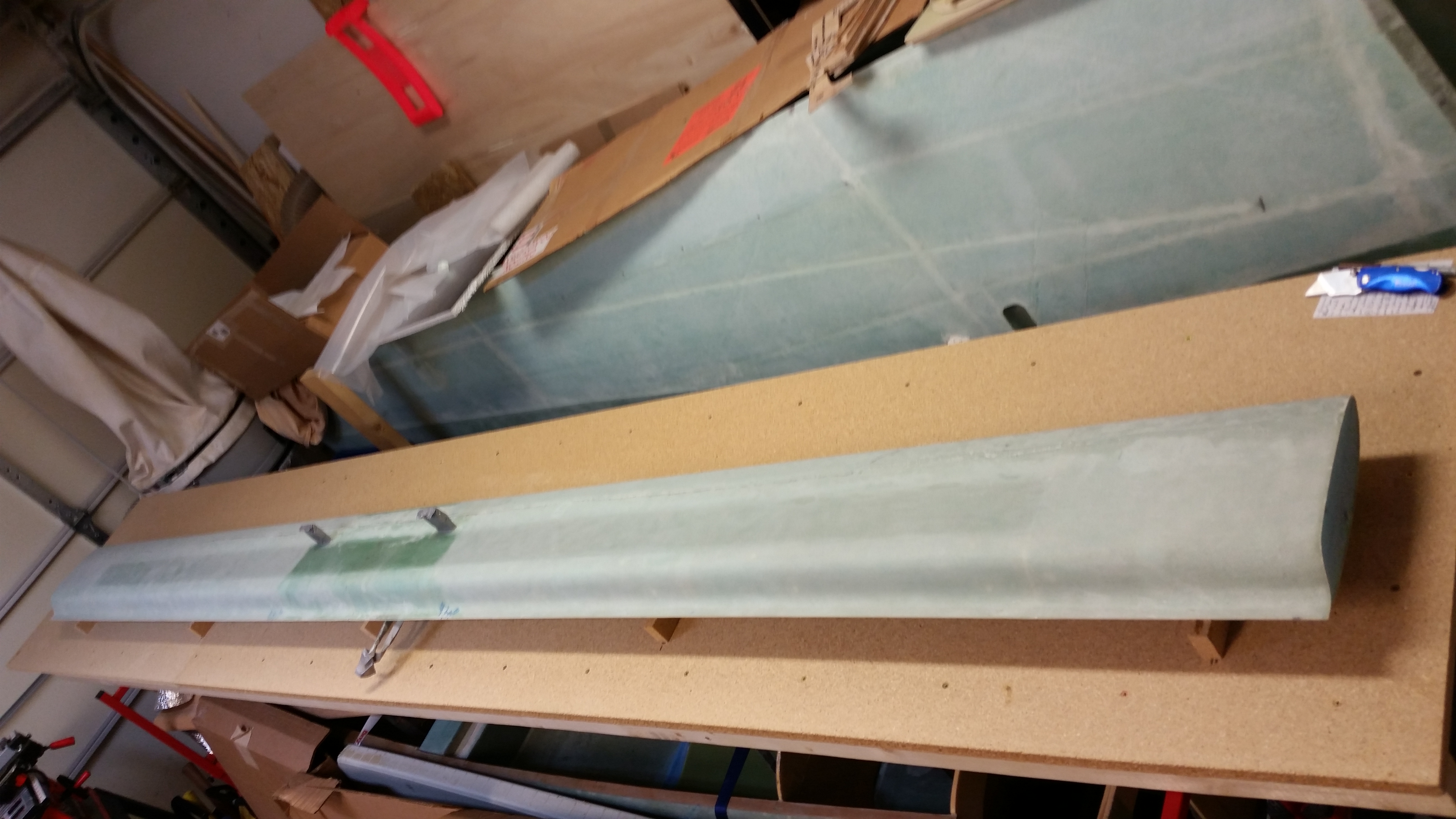
After calculating the distances between the 5 “K” mounts I’m going to use, I then mocked up the canard upside down on the “K” mounts to ensure a study platform on which to finish the bottom side of the canard.

Now, if you’ve seen Wayne Hicks’ webpage on how to finish the canard, then you’ll know that he uses a 3-4″ wide sanding block which is essentially nothing more than a widened contour template that is adjustable in height and which a wide piece of sandpaper can be attached on the inside of the contoured area.  Well, on his site Wayne explains that you can’t finish the bottom of the canard using the contoured sanding block setup because of the multiple installed elevator hinge mounts that get in the way.

So, a few years ago when I was talking to Randi (aka “Cozy Girrrl”) she gave me a ninja tip to finish the underside of the canard first, then not only would I have a more concise measured gap between the aft tail of the canard and the front of the elevators, but I would also have eliminated a lot of pain & strife trying to finish that bottom of the canard with those darn elevator hinge tabs in the way!  Plus, not only would the finish look much cleaner & nicer, but it would be more aerodynamically correct.  A win-win if you will.

One last thought on finishing the bottom of the canard now, is that as simplistic as it sounds, it will be finished.  And since I plan on finishing the entire canard & elevators before storing it away until later, it will be one less thing I have to finish when I “hit the wall” that is Chapter 25 (aka “Finishing”).

Test mounting Canard

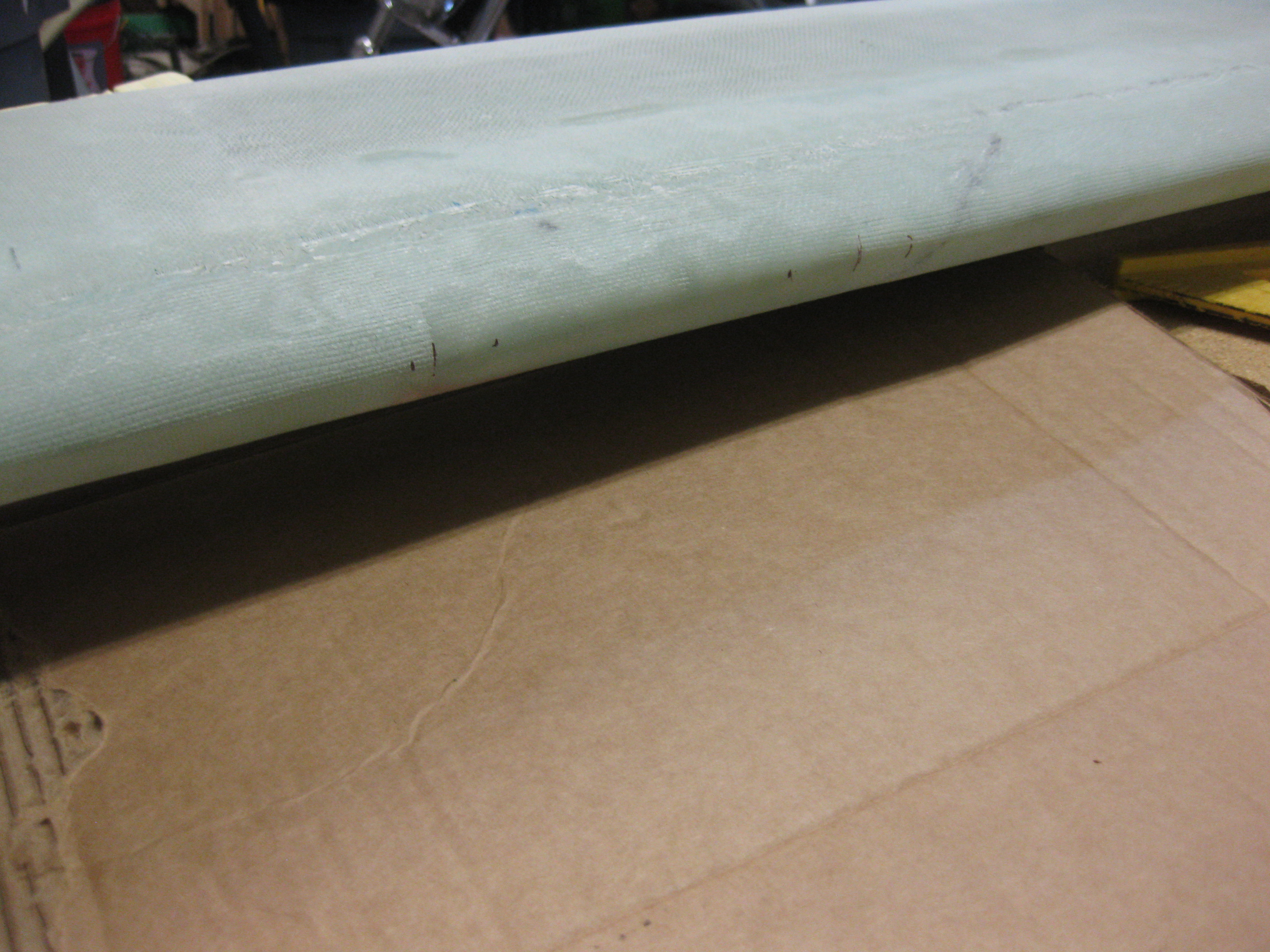
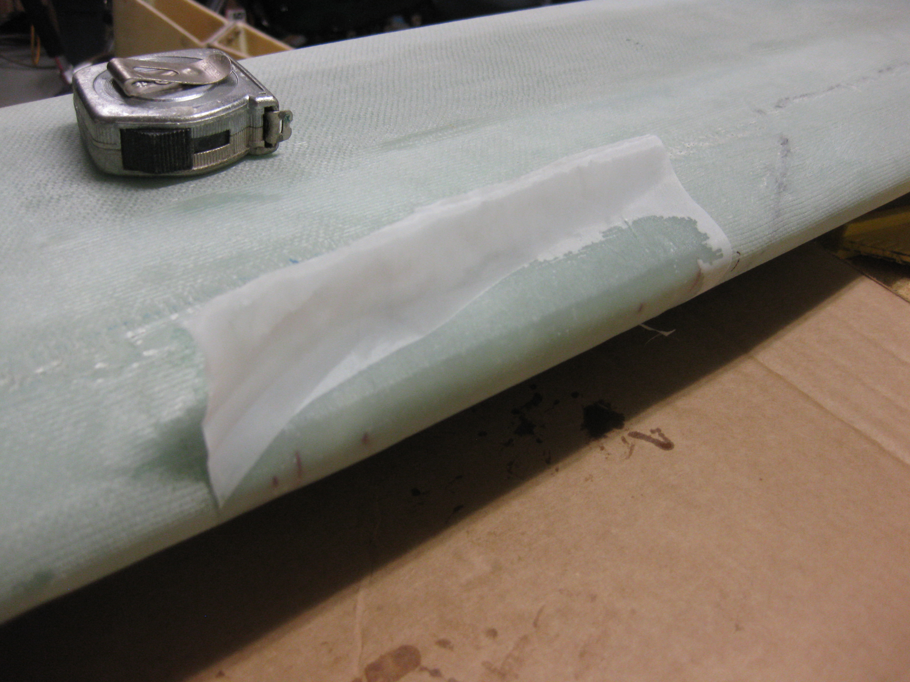
The first actual step that I needed to complete was repairing the Leading Edge of the canard.  You see, back when I glassed the canard as I was pulling the duct tape off the leading edge after the bottom skin had cured, it pulled out a pretty big chunk of the leading edge blue foam underneath.  With the canard being upside down, and with some foam missing under that 4″ leading span, the bottom skin glass naturally depressed a little right in that area as it cured.  When I flipped the canard to glass the top, I had to back fill micro behind that 4″ deformed area on the LE to account for the missing foam.

Canard LE distortion during glassing

When I did the glass layup on the top of the canard, I could tell that I was going to have to repair that damaged LE area later on by adding a few plies of glass.  To “mark” the LE area that would required repair, I simply peel plied it.  The peel plied area on the LE was thus my marker for the future on the exact area that needed further work.

Canard LE distortion

Well, the time to repair the canard LE has finally come . . . after about 2-1/2 years since I finished the canard. (Wow, time flies!)

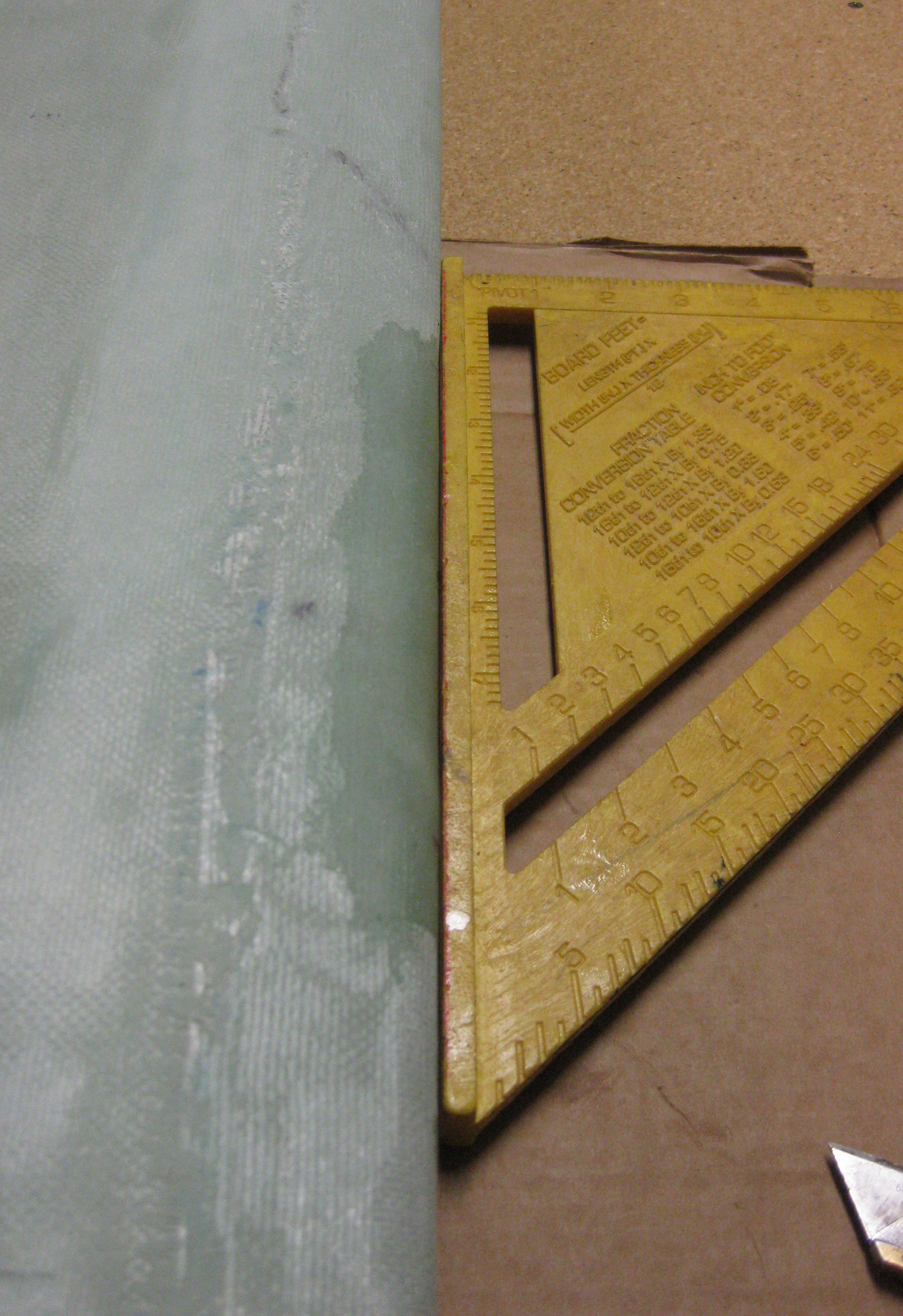
I took a straight edge to the front of the canard to get an idea of how much glass to add.  I determined I would only add two plies of BID: a) 3/4″ x 4″ and, b) 1-1/2″ x 5.2″.  These would give me just enough glass fill that, after sanding, the remaining surface irregularities would easily be filled by the finishing micro.

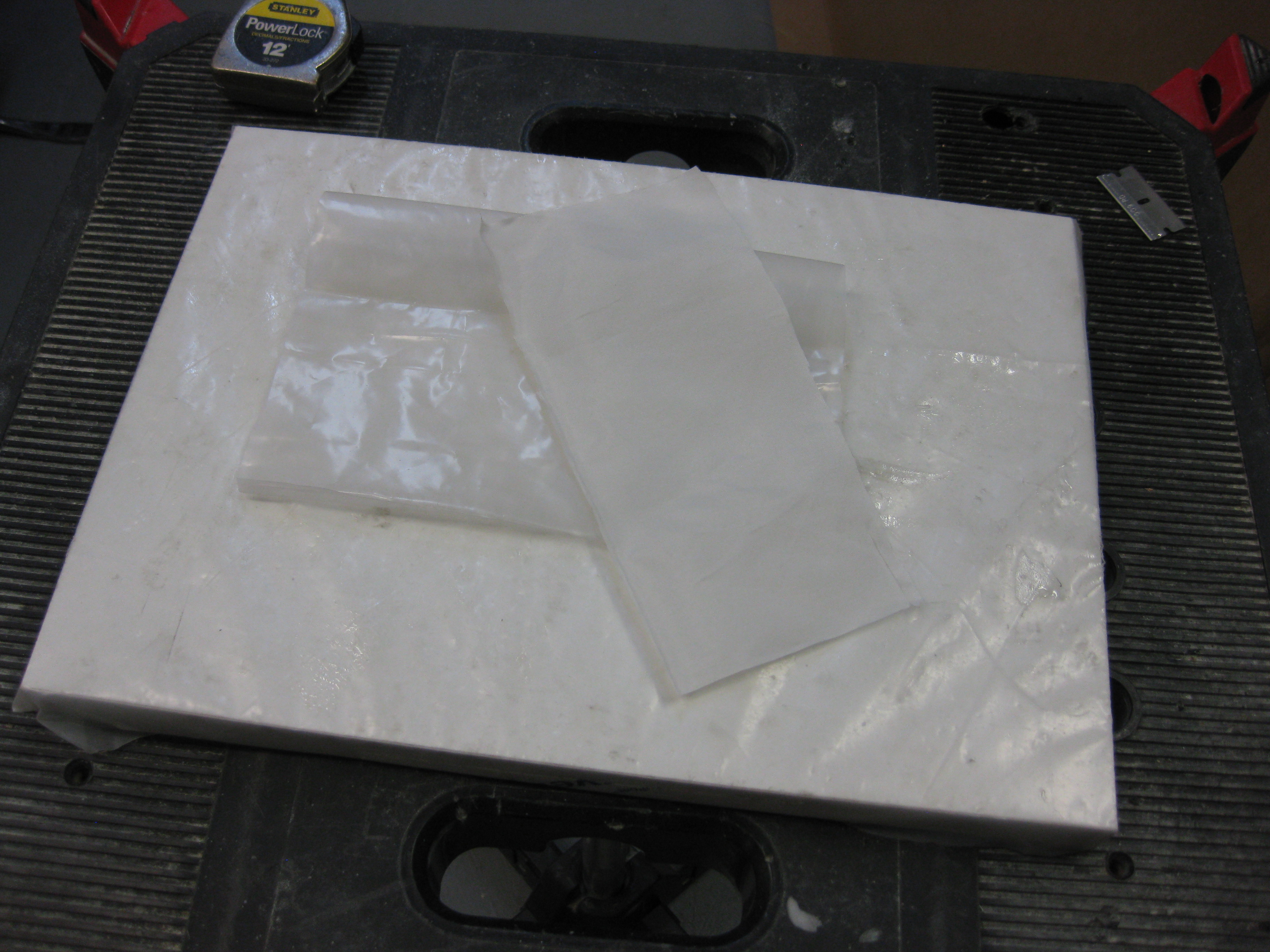
As per my usual, I will pre-preg this layup so I cut out a small piece of plastic and prepped my peel ply.

Prepping for canard LE patch

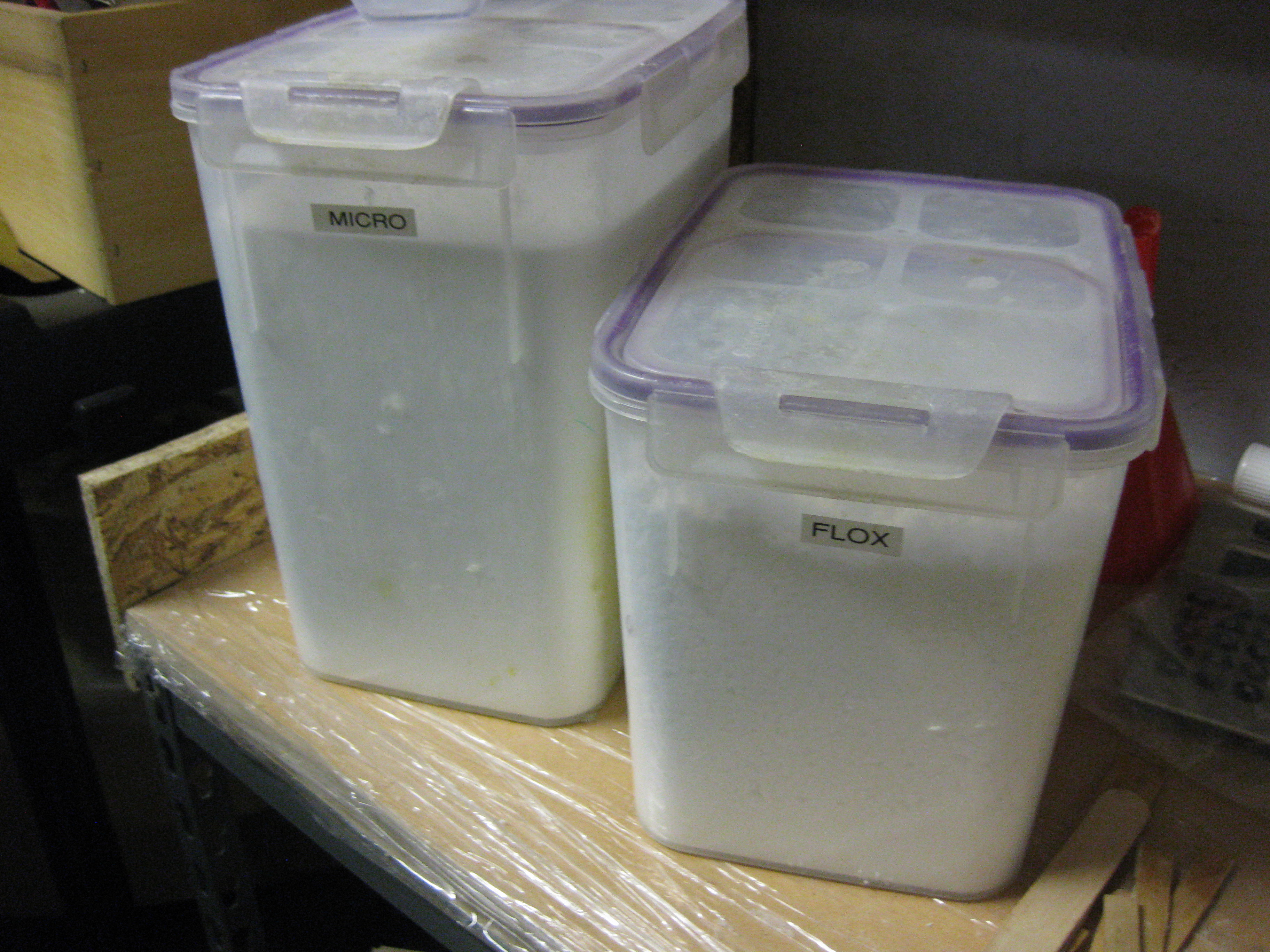
Before getting started on my new build quest, I had to reload both my stock of micro and flox, each container being almost completely empty!

Reloaded for upcoming build operations!

Below is the freshly laid up 2 plies of BID.

Canard LE 2-ply BID patch laid upBelow are a couple shots of the finished layup peel plied.

Canard LE BID patch peel-pliedCanard LE BID patch peel-plied


As the LE patch cured, I started working on the canard lower contour sanding block.
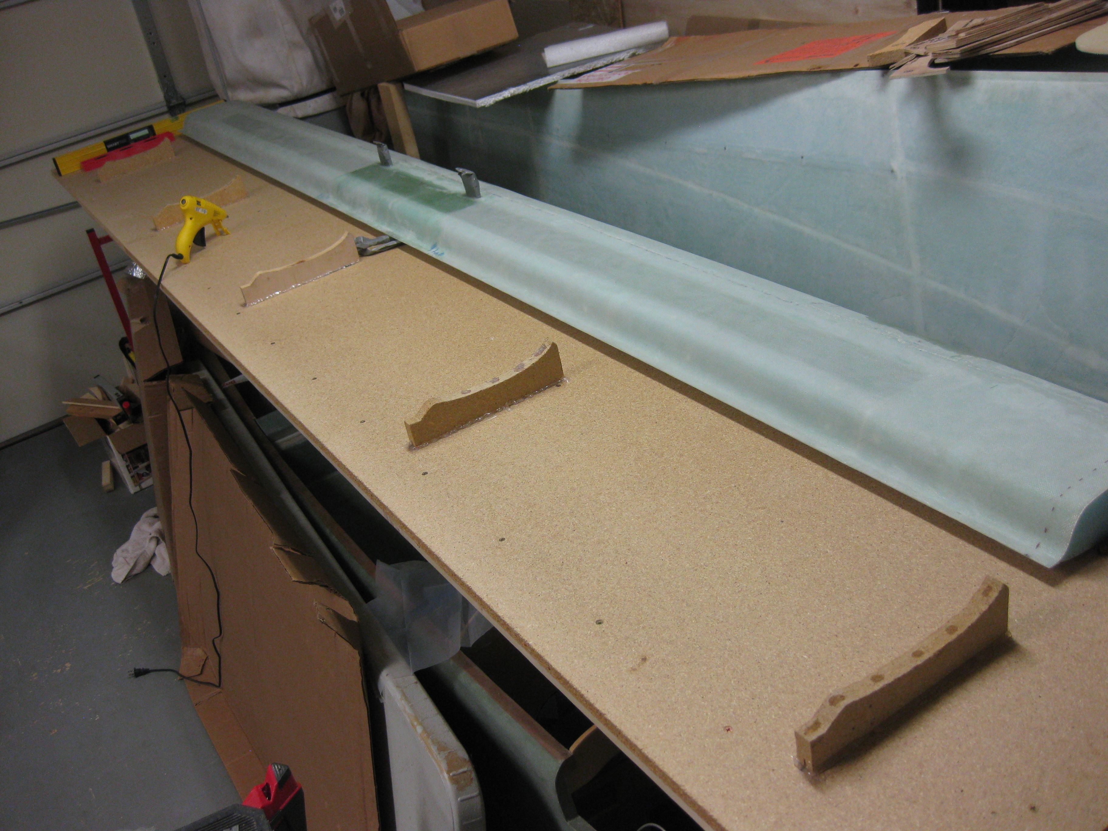
Building a Wayne Hicks canard finisher

A few hours later I pulled the peel ply off the 2-ply BID patch.
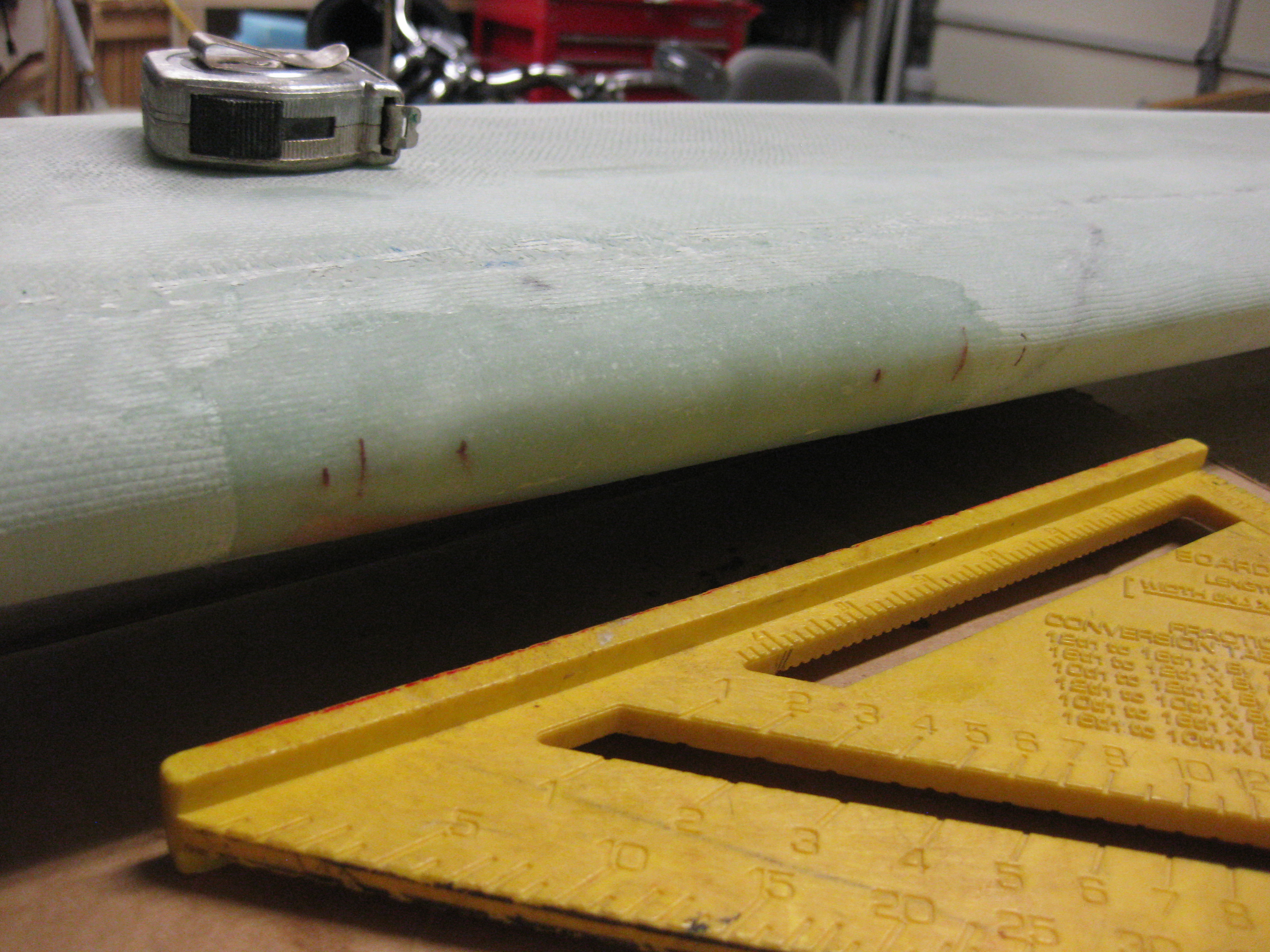
Cured LE BID patch

And then tested the patched LE area against a straight edge.  There are still a few minor  irregularities, but nothing that can’t be handled with a little bit of sanding and some micro during the finishing process.

Canard LE patch improved lines immensely


Chapter 21 – Strake Leading Edge Kit

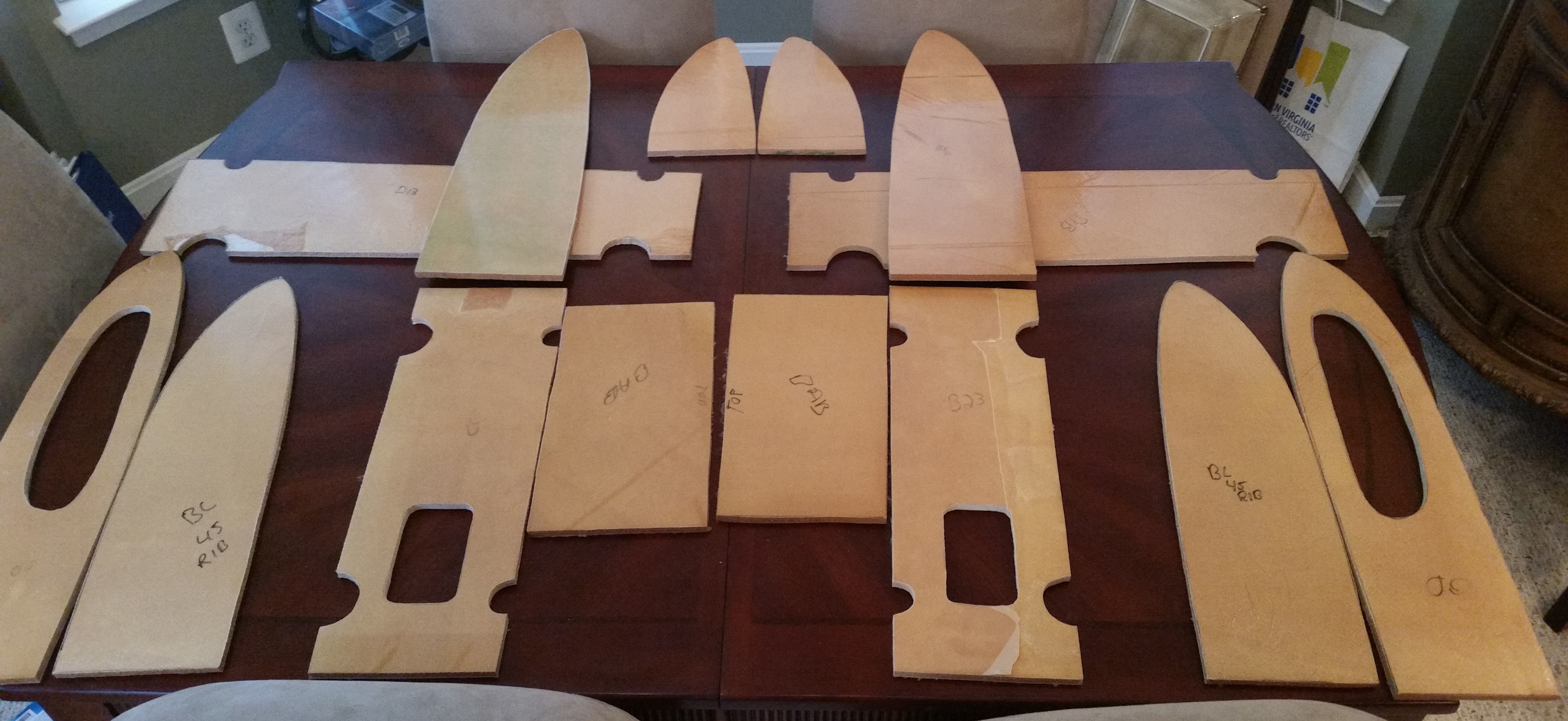
After getting settled back in from being at Rough River this past weekend, I set about to do a proper inventory of all the strake ribs and fuel tank baffles from the Feather Light Strake Leading Edge Kit that I bought off Nate Mullins back in late 2013 and finally just picked up.

Here’s a shot of them below back AT MY HOUSE! The pieces all have a shiny covering on them which is just an extra layer over the peel ply.  All the parts will need a final trim before final installation, but having these parts pre-glassed and pre-cut should save me days on the strake build.

Feather Light Strake Kit

I cleaned up the inside glass of the leading edge pieces, and then set up for a pic before they were  stored away once again.

Feather Light Strake Leading Edges


Rough River 2015 – My First!

Well, after years of attempting to make it to the annual Canard Gathering at Rough River, Kentucky I was finally able to make it!  I arrived Friday early evening and met a bunch of my building buddies and hung out for a couple of hours before heading off on another hour+ track to Madisonville, KY to meet my buddy Richard who has been storing my Feather Light Strake Leading Edge Kit since late 2013.  (I’ll show pics of the kit in the next post).

Rough River 2015

Rough River 2015

After spending the night at Richard’s place, I packed up the Feather Light Strake Leading Edge Kit Saturday morning, went out to breakfast with Richard and then took off back to RR to spend the day with fellow Canardians!

Rough River 2015

I met a bunch of the Old Guard while walking around checking out the planes: Terry Schubert, Nick Ugolini, Vance Atkinson, Bill James, Jack Wilhelmson, just to name a few.  And of course Chrissi and Randi (the “Cozy Girrrls”) were there scooting around on Segues.

There was a home builder with a Turbine Legend that gave a few people some incredible rides, and he showed off his incredible airplane a bit too.  In the pic below he’s doing an amazingly fast fly-by:

High Speed Flyby RR 2015

One point of note that could not go without notice is the number of VariEzes that were at Rough River this year.  Now, since this is my first RR I obviously don’t know how many normally show up, but according to a bunch of folks there, this was apparently the most VEs that have shown up in a long, long time.  To commemorate the 8 VariEzes that were present, they had the owners line them all up to get some good pics of the lot:

VariEze's at RR 2015VariEze's at RR 2015

Finally, what would be a canard gathering be without a salute to canards by a formation of EZs:

EZ's in Formation RR 2015

I had a blast and it was both wonderful and highly motivating to see all those canards there (although apparently there was just a little over half the number of planes that normally show up).

Probably even more motivating to get me back to work was the sheer amount of driving it took to get there!  That in and of itself is reason enough for me to knock out this bird so I never have to DRIVE to Rough River again!  Cheers.

Chapter 10 & 25 – Sandblasting Canard

I put this post under both chapters 10 & 25 because prepping the surface of the canard is a prerequisite for not only finishing the canard, but to glassing the canard “swoosh” tips to the canard & in optimizing the elevator install process.

How?  Well, in yet another discussion with Randi from the infamous Cozy Girrrls, she highly recommended finishing the bottom side of the canard BEFORE mounting the elevators to exponentially decrease the time & effort it takes to finish the bottom of the canard with all the elevator mounting tabs in place.  In addition, it helps knowing what the bottom contour of the canard will actually be when determining the spacing between the elevators & the aft edge of the canard.

As per Wayne Hicks, and so many other Canardians, I decided that the easiest, less-destructive route for prepping the surface of this plane for finishing would be sand blasting. It’s faster and clearly it can prep the fibers that lie slightly below the surface as compared to the “taller” fibers without having to destroy the strength & integrity of the outer fibers–as one would have to do if sanding the surface in preparation for finishing.

Un-sandblasted SurfaceUn-sandblasted Surface

I personally find the texture, gleam & appearance of well laid-up glass (above) wonderful, as I’m sure a lot of other folks that work with fiberglass do as well.  But of course this surface can’t remain for the final finish, so we must often cover up some of our best work (and thankfully our not-so-best!) under micro!

Un-sandblasted Surface

I wanted to add this shot below for my fellow builders who don’t use MGS.  I still am impressed by how a line drawn on the shear web can still be seen after ~10 plies of 3″ UNI tape have been laid up over it.  As a user of MGS, it will be especially interesting to finish the surfaces of these “transparent skinned” components into a solid-colored airplane.

The miracle of MGS-285!

As I’m sure most of you are aware, I had some definite sandblasting woes when trying to sandblast the rollbar before priming it.  I have since done a lot of research and am hoping that I can get this sandblaster to work well enough to finish at least the canard, then I can reassess.

I started by taping up the antenna leads to protect them from any errant sandblasting.

Antenna leads protected

I then did the same for the canard mounting tabs.

Mounting tabs protected

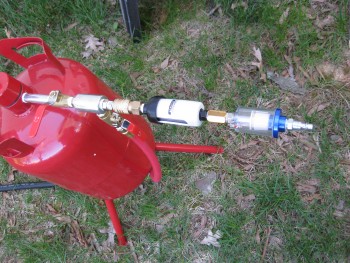
One issue that I wanted to avoid that was a possible contributor to my sandblasting woes was ensuring that the air I was using was CLEAN & DRY.  I bought & employed a couple of inline filters & combined them with the appropriate air connectors into an assembly that I jokingly called, “the Kraken.”  I then mounted the Kraken to the air inlet on the sandblaster.

The Kraken!

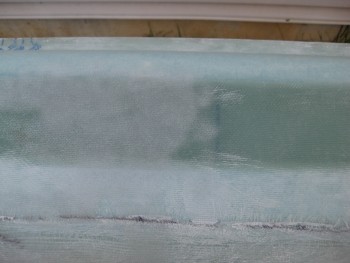
I then employed all the tips, tricks & processes that I had learned about this somewhat cheap sandblaster, and although it’s still not a pleasure to use, it at least gets the job done now.  You can definitely tell the areas that were sandblasted & those that weren’t.

Sand blasted vs non-sand blasted

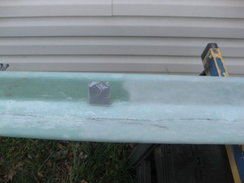
Just as Wayne Hicks described his sandblasting experience on his Cozy IV build site, the sandblasting textured the canard surface perfectly and didn’t damage it in any perceptable way.

Sand blasted vs non-sand blasted

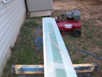
Thus, stopping every few minutes for both the compressor to re-build up pressure, and clearing out the subsequent plugged-up nozzle from the decrease in pressure, I was able to knock out the bottom right side of the canard in about 40 minutes.  With a bigger, higher quality sandblaster I’m sure I could have cut that time in half, but I’m more than happy with the time, effort & cost required to attain the results that I did.

Right-side bottom sand blasted

Another technique I employed in optimizing the sandblaster’s ability to simply work was to bring my compressor out to the job site.  Instead of running 2 lengths of air hose, I simply used one.  The first time around I used 2 hoses, with one of them being rubber. Apparently rubber hoses allow much more moisture buildup, as does longer lengths of hose.

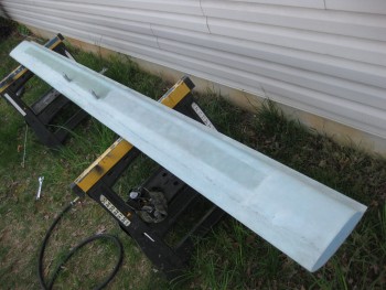
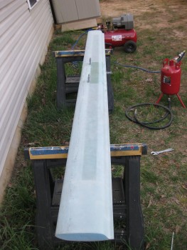
So somewhere in both using the correct sequence in the opening of the 4 valves on the sandblaster, and the corrective measures I took to ensure clean, dry air, I was able to sandblast the entire bottom side of the canard.

Bottom-side canard sand blasted

At one point fairly early on, I did have to empty the sandblaster of all the media and fill the sandblaster hopper with smaller amounts to keep it from clogging up.  But again, that was a minor annoyance in comparison to being able to sandblast this thing on the cheap.

Since it started getting dark, on the topside of the canard I simply sandblasted the edges at the inboard areas where I will need to finish the canard, and the glass covering the outboard extensions which need surface prep for the upcoming glassing of the “swoosh” tip extensions.

Topside canard

All the sandblasting I accomplished today on the canard actually meets all my requirements for completing chapters 10 & 11.  However, I will finish sandblasting the top of the canard since as I mentioned before, my plan is to actually finish the entire canard & elevators to paint.


Chapter 25 – Finishing

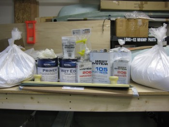
Just a quick post to show that over the past few months I’ve been stockpiling various stuff I’ll need for finishing the canard & other parts of this bird.  I know a fair number of builders don’t care for using West for the final finishing, but I don’t have any issue with it & so when it goes on sale I’ll pick up a gallon of it to add to the inventory.

Finishing Stuff

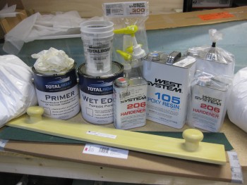
And as you can see by the pics, my initial plan is to use boat paint for the primary finish.  In addition, as per Wayne Hicks’ recommendation I picked up some 3M Hookit Long Boards & sandpaper for the wings and other large areas.

Finishing Stuff

If all goes according to plan, I’ll be putting this stuff to good use when I finish the canard.


Chapter 16 – Dissecting the throttle handle

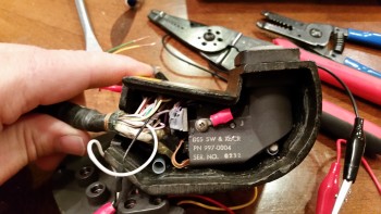
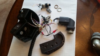
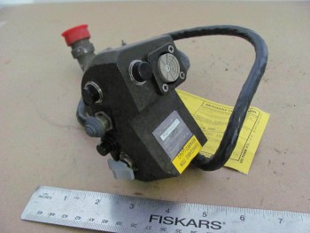
My original thought when I acquired my new F-15 throttle handle was to simply test all the individual pins & create a wire map of all the switch circuits.  Well, with a 37-pin cannon plug, that was a little easier in thought than in practice.  After hunting & pecking for a while, I decided that it was time to dissect the throttle handle and see what exactly I was dealing with . . . and I’m glad I did.

I had already made up a pin-out diagram for the cannon plug & numbered each pin.  Since I wasn’t able to figure out the circuits for the switches or visually see them, I clearly wouldn’t know their functioning until I cracked this thing open.

F-15 throttle handle disection

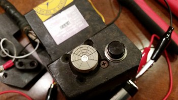
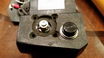
The first thing I saw when I opened the throttle handle up was the flat joystick-style switch that sits on the outboard, front side of the throttle handle.  It took me a while to carefully dig out the potting material & get the wires situated to the point that I could finagle this thing out of there.  It was a very tight fit!

F-15 throttle handle disection

F-15 throttle handle disection

I then began digging out the other top switch from its potting goop.  I identified the wires & listed them by color on another sheet of paper.  I set about confirming their connections by performing a continuity check by placing one side of my test lead on a switch terminal, then at the cannon plug side I would simply swirl the test lead around until the voltmeter rang out.  Then I would annotate it on my diagram.

Dissecting F-15 throttle handle

After I finished the top switch & had all its info documented, I would then spend another 20 minutes or so excavating the next switch from its potting material prison.  Once its leads were exposed, I again performed a continuity check to figure out the cannon plug pins.

Dissecting F-15 throttle handle

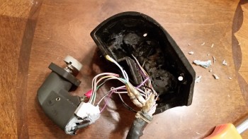
After determining the wiring schema for all the switches on the throttle handle, I discovered some key pieces of information:

a.  I am going to completely rewire the switches in this throttle handle.  Clearly these switches are configured for specific discreet electrical components on the F-15, as evident by the myriad of capacitors, resistors, etc. hanging all over each switch.  Plus, there is far more extra capacity with a 37-pin cannon plug than I am going to need to drive my components with the switches on hand.  My initial thought is that even a 23-pin plug will give me plenty of future scalability.

b.  I’ll be removing the pistol-shaped switch that engulfs the entire interior left side of the throttle handle.  It may provide more capability when linked to specific F-15 systems, but in my case it only offers me a single-position momentary on.  It takes up a lot of real estate and it’s heavy, accounting for almost 20% of the current weight of this handle.  If I get rid of this switch by replacing it with a nearly externally identical Otto switch (with much smaller internal guts), reduce my throttle handle wiring harness by nearly half the wires, and use a smaller plastic AMP connector, I think I could reduce the weight of this handle by about half (about 0.65 lbs).

For those of you that are curious about the current throttle handle switch functions, they are listed below this pic in order starting at the top right-hand switch (flat grey) moving CCW.

F-15 Throttle Handle

1.  Grey flat joystick style: single momentary on (TBD).
2.  Black push button: PTT – single momentary on.
3.  Black push button: single momentary on (GTN650 remote or Trio AP fuel data)
4.  Metal china-hat toggle: ON-OFF-ON (possibly air brake)
5.  Black push button: DPDT dual momentary on (TBD).
6.  Grey-capped toggle:  3-position (broken lead/functioning TBD… ON-OFF-ON?)
_________________________________________________________________________

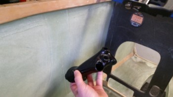
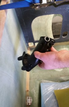
Also, as I mentioned in my last post, for those of you that are curious about the size & fit of the F-16 throttle handle, I shot a couple pics to show what I was talking about.

F-16 Throttle Handle Comparison

Not terrible at all, but definitely takes up more space than I’d like it to inside the Long-EZ cockpit.

F-16 Throttle Handle Comparison