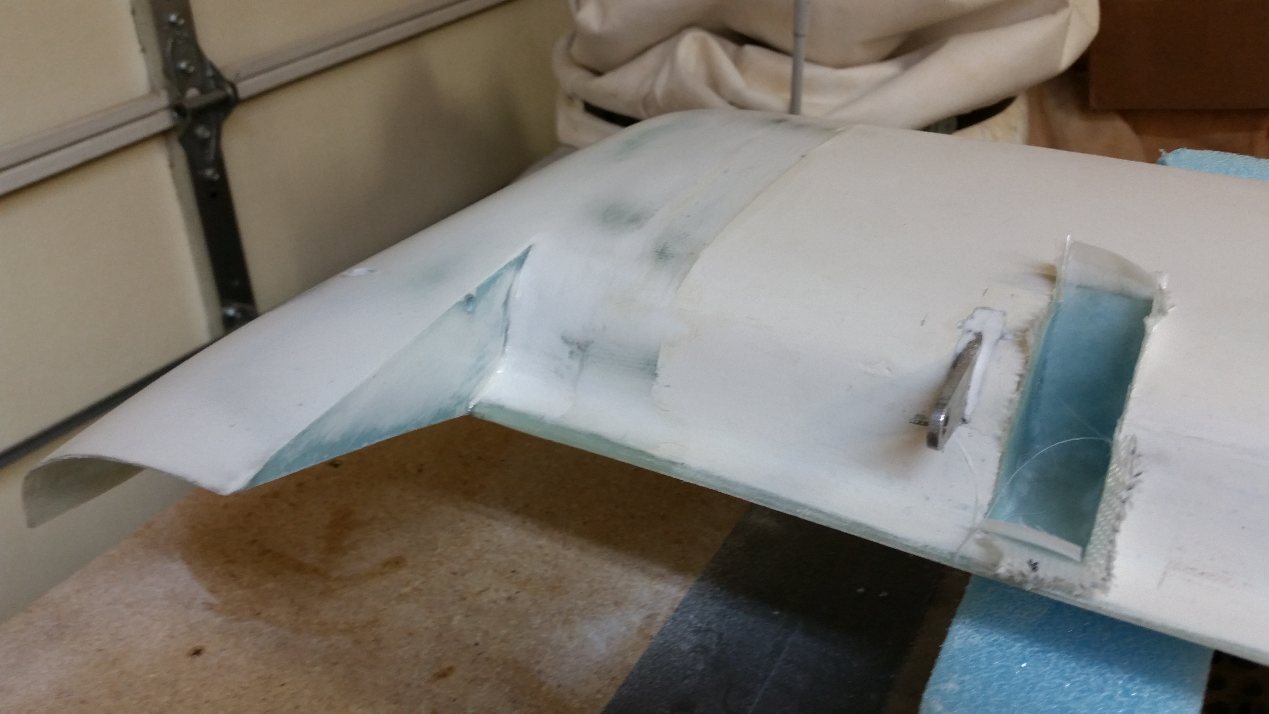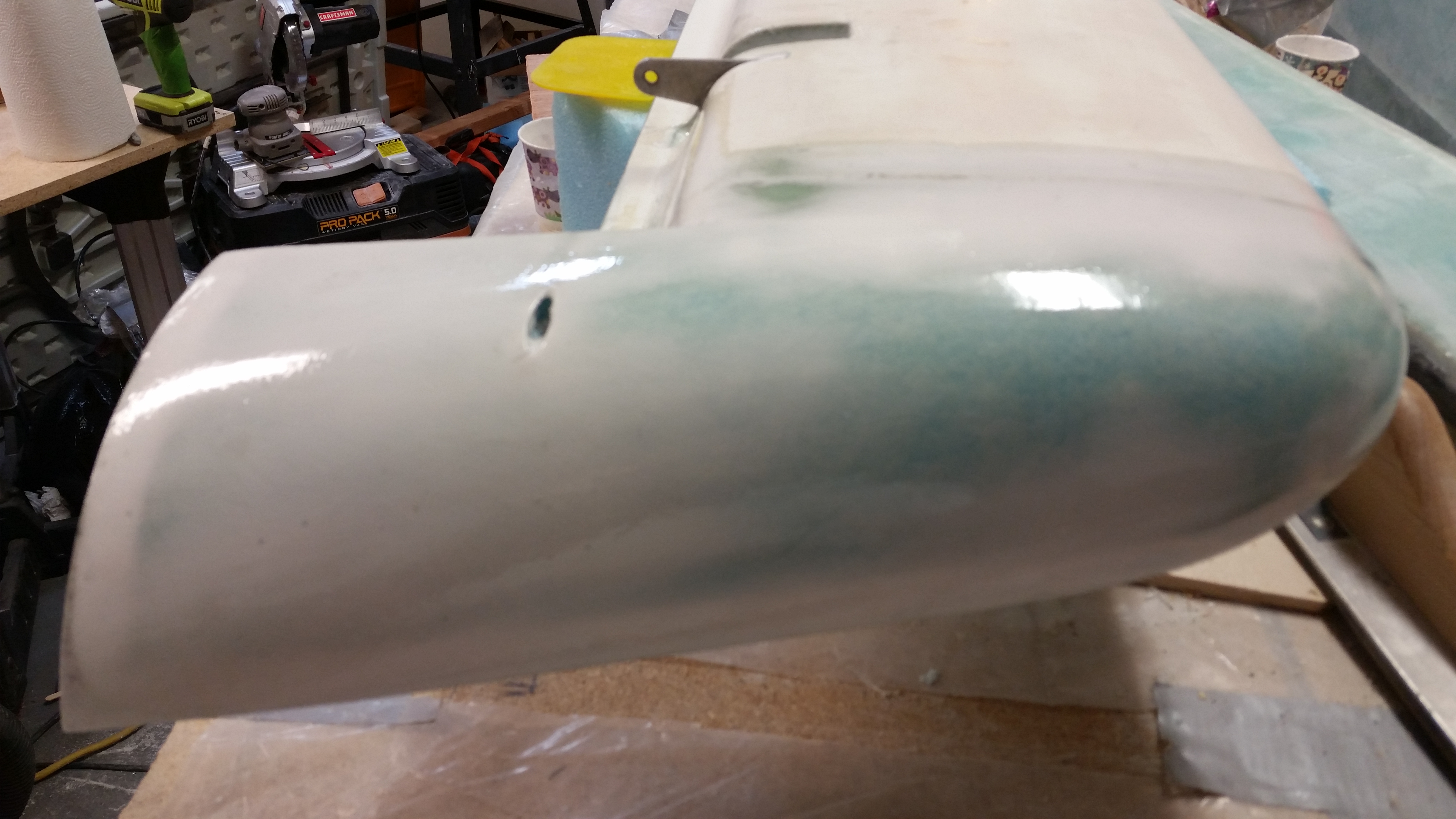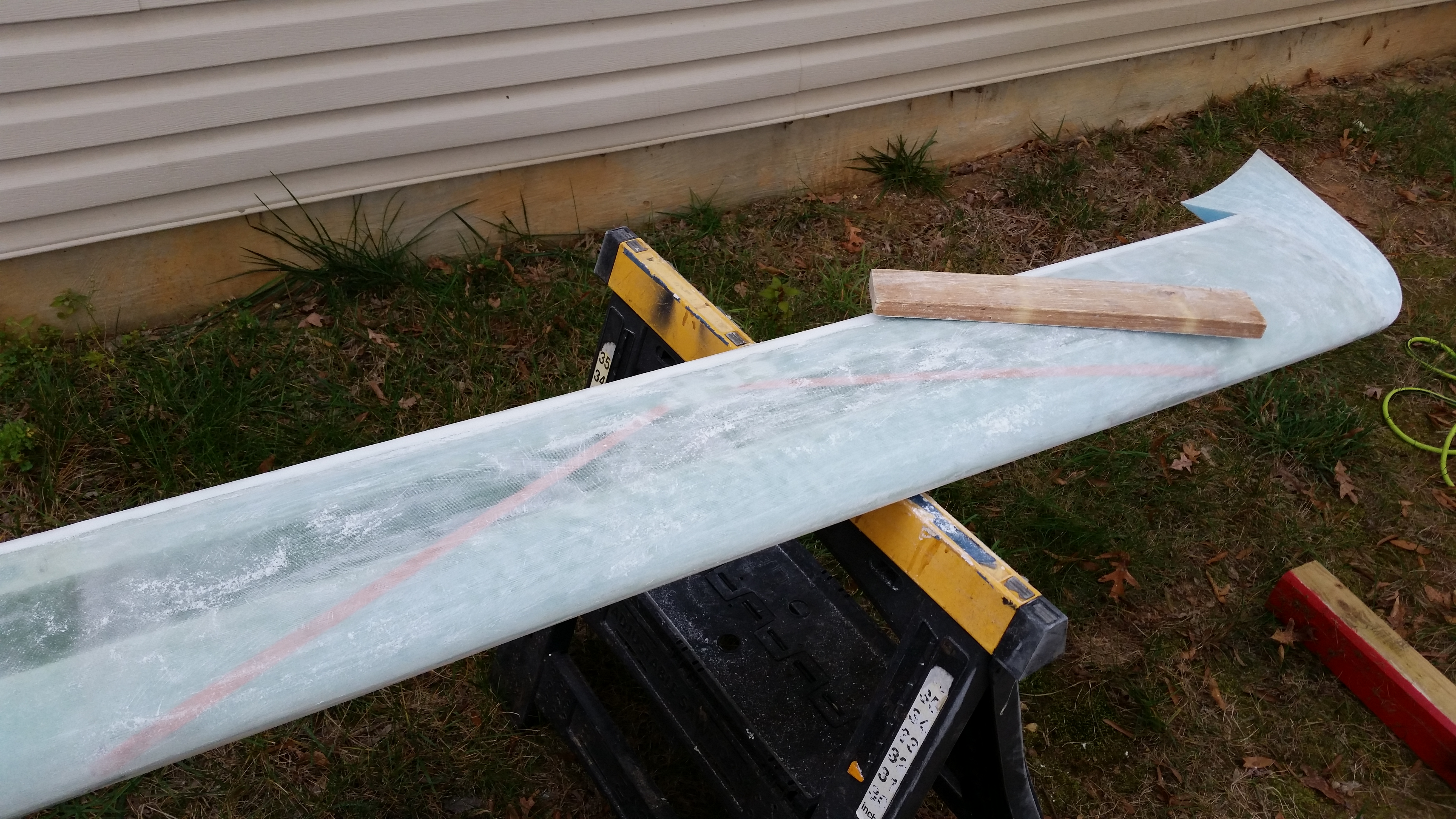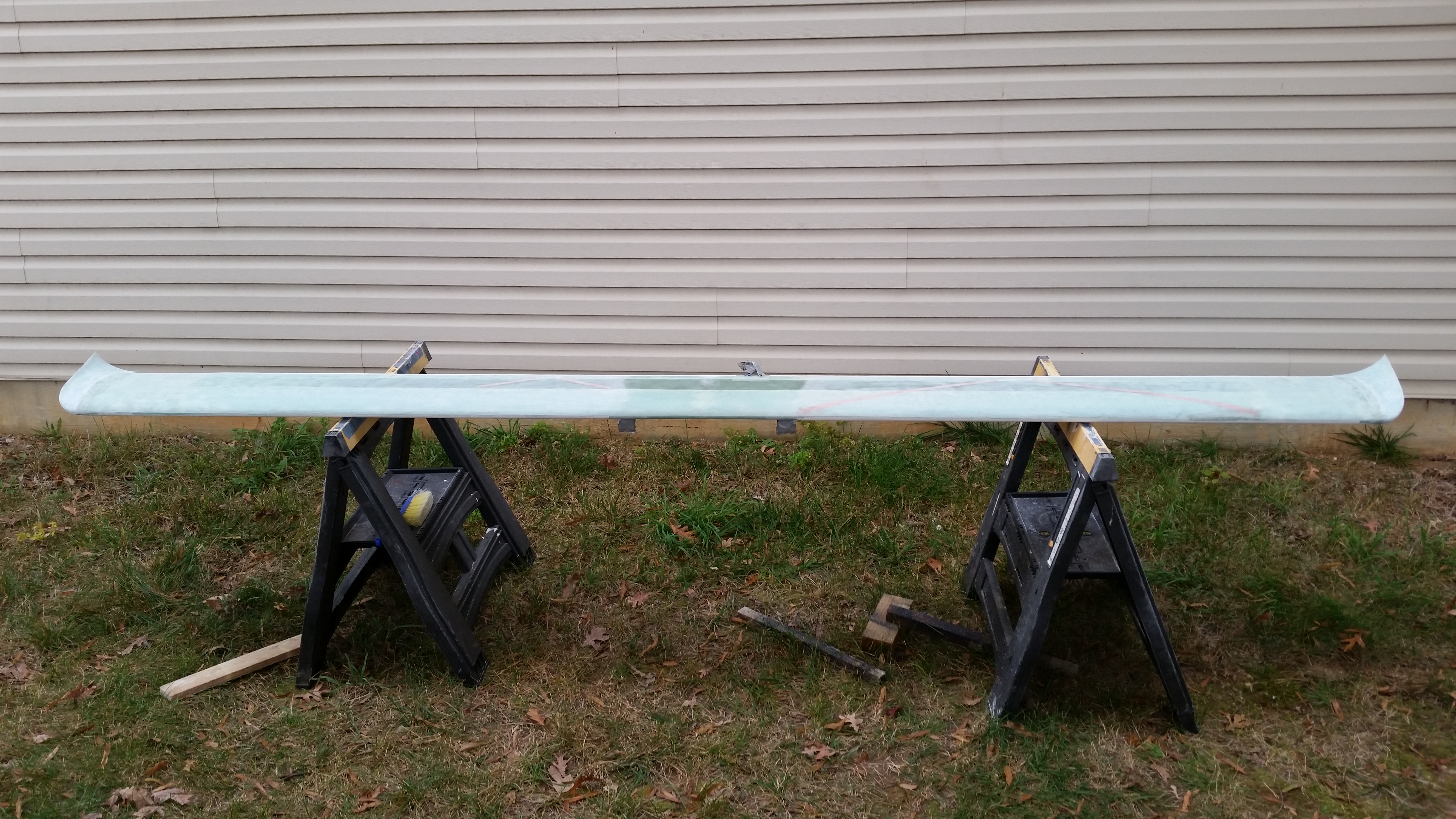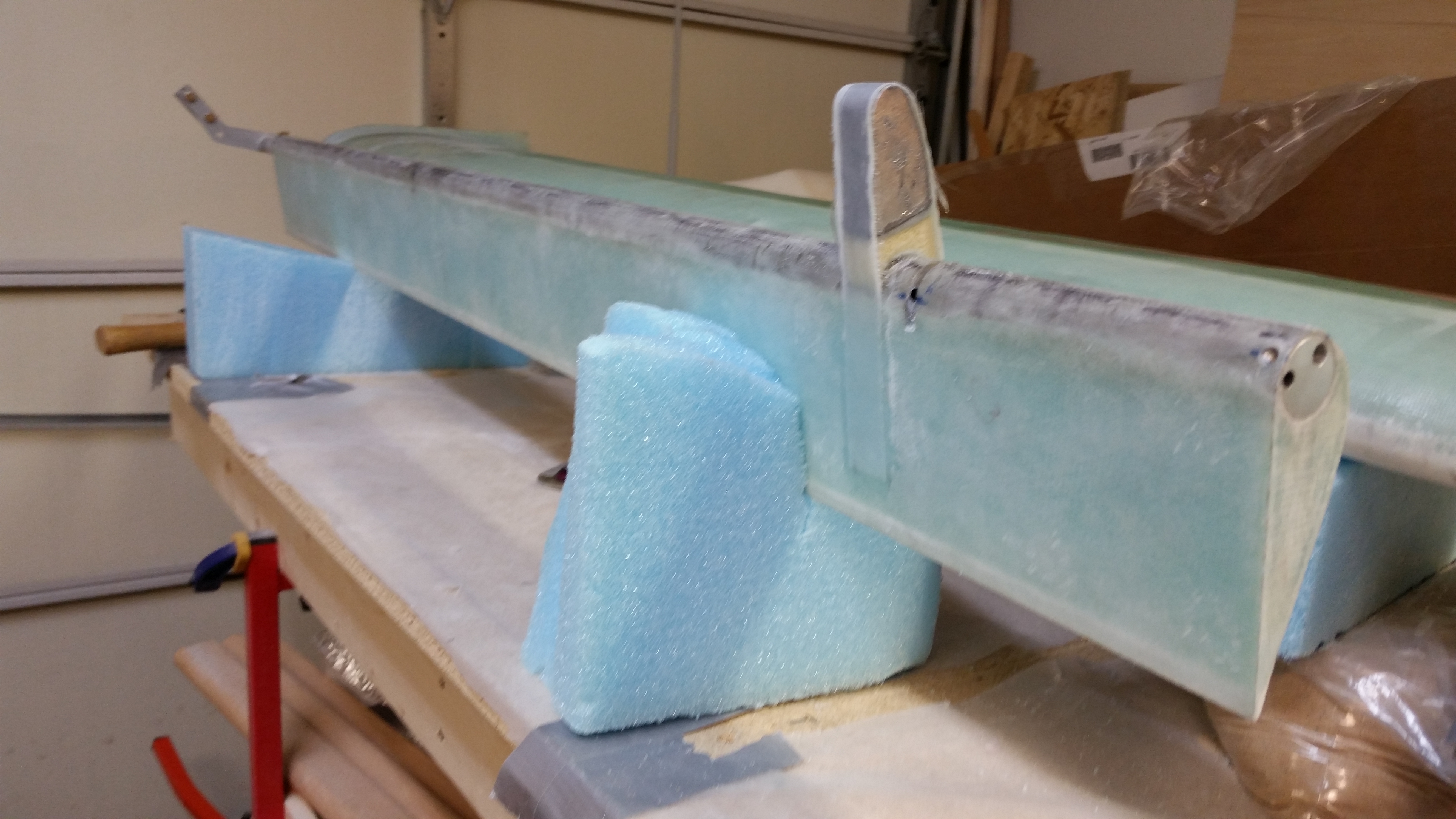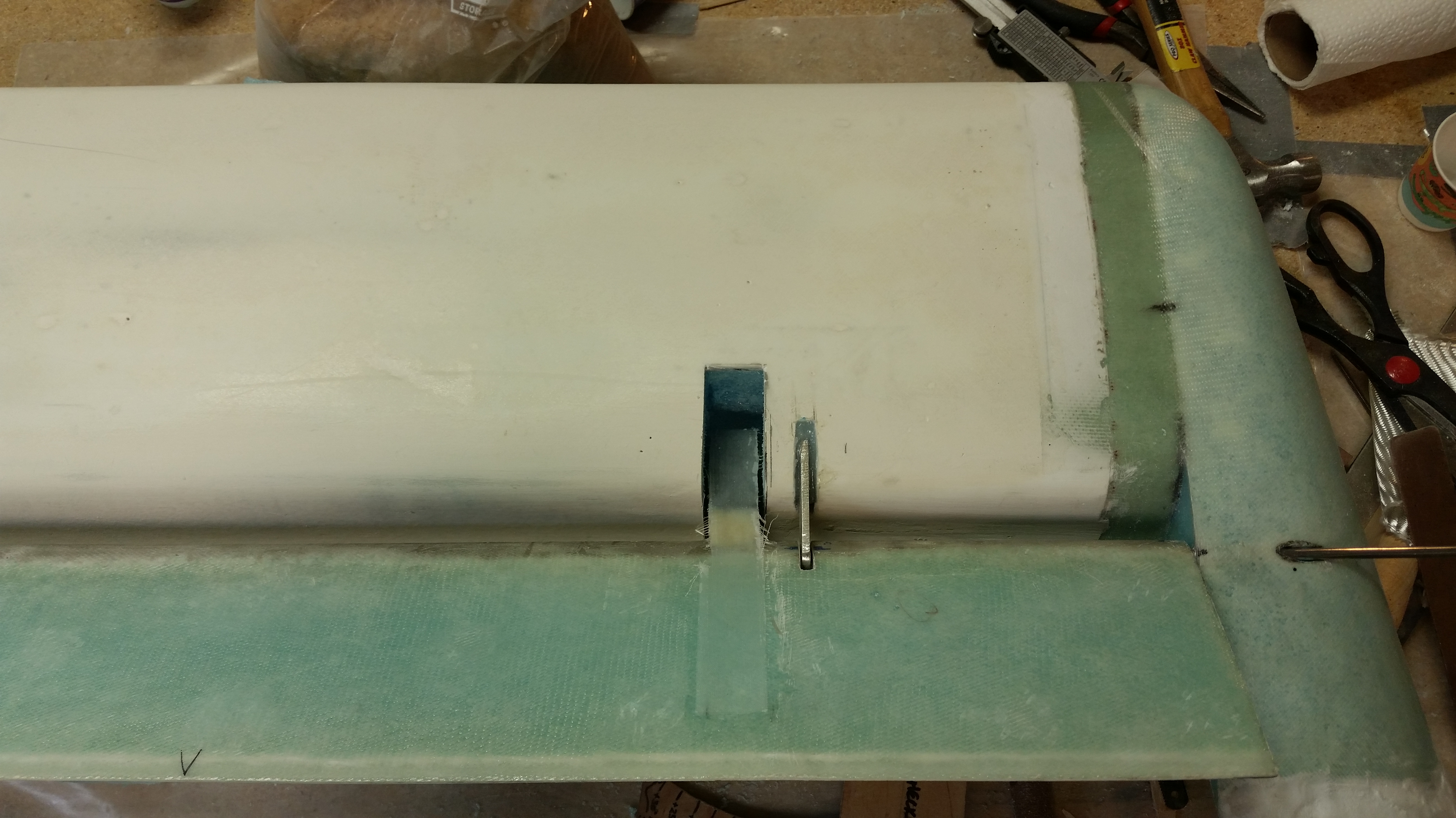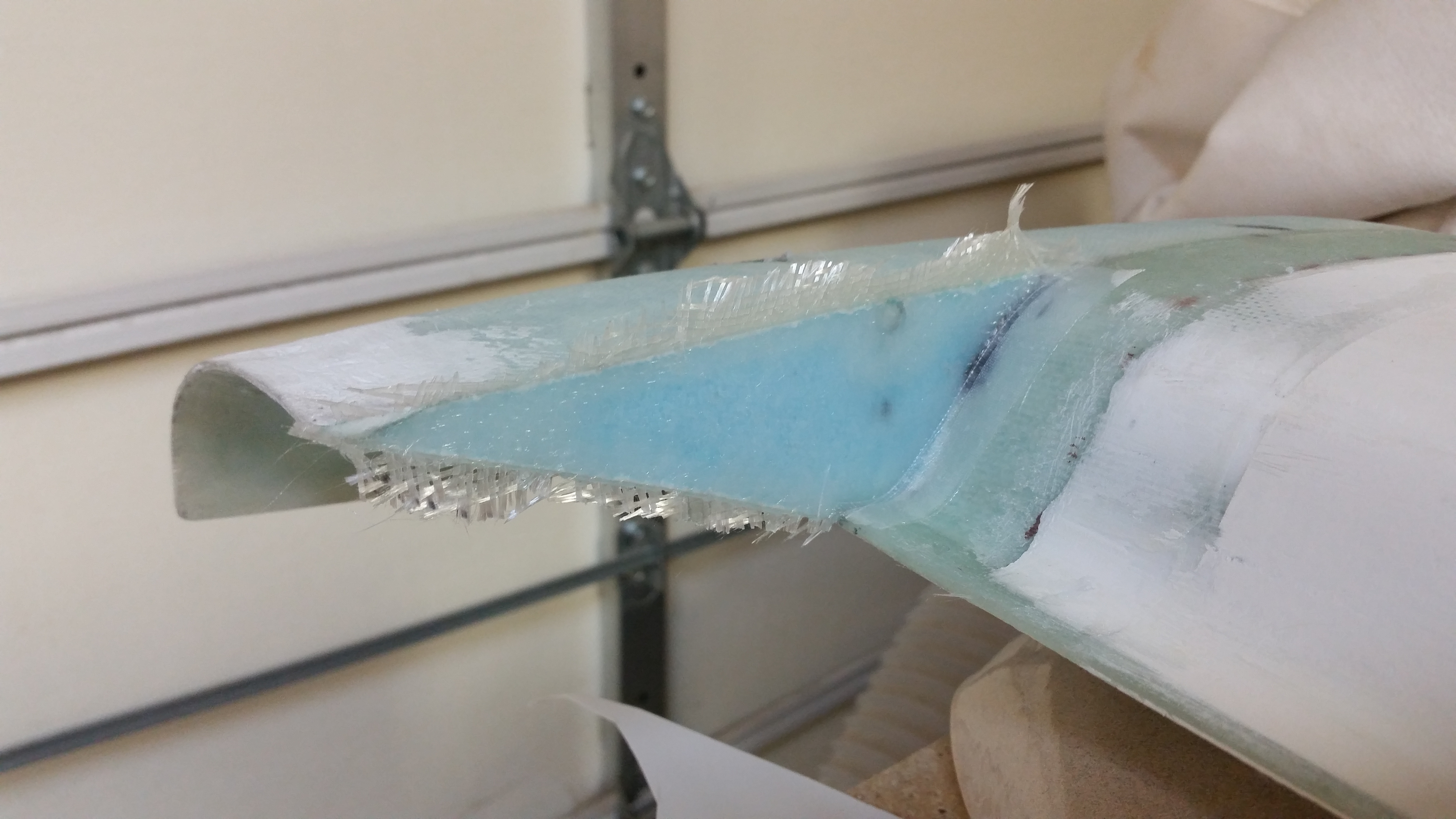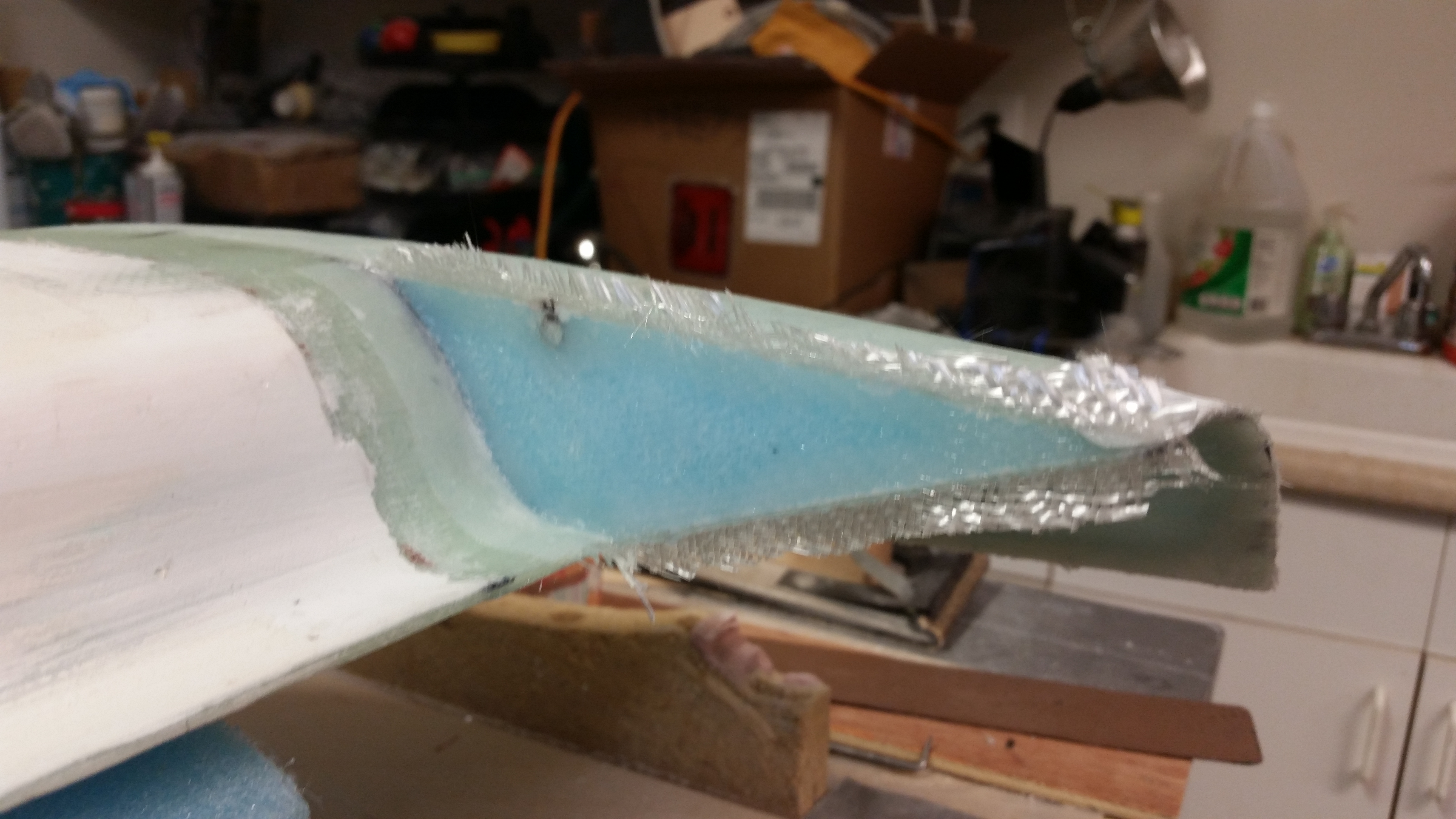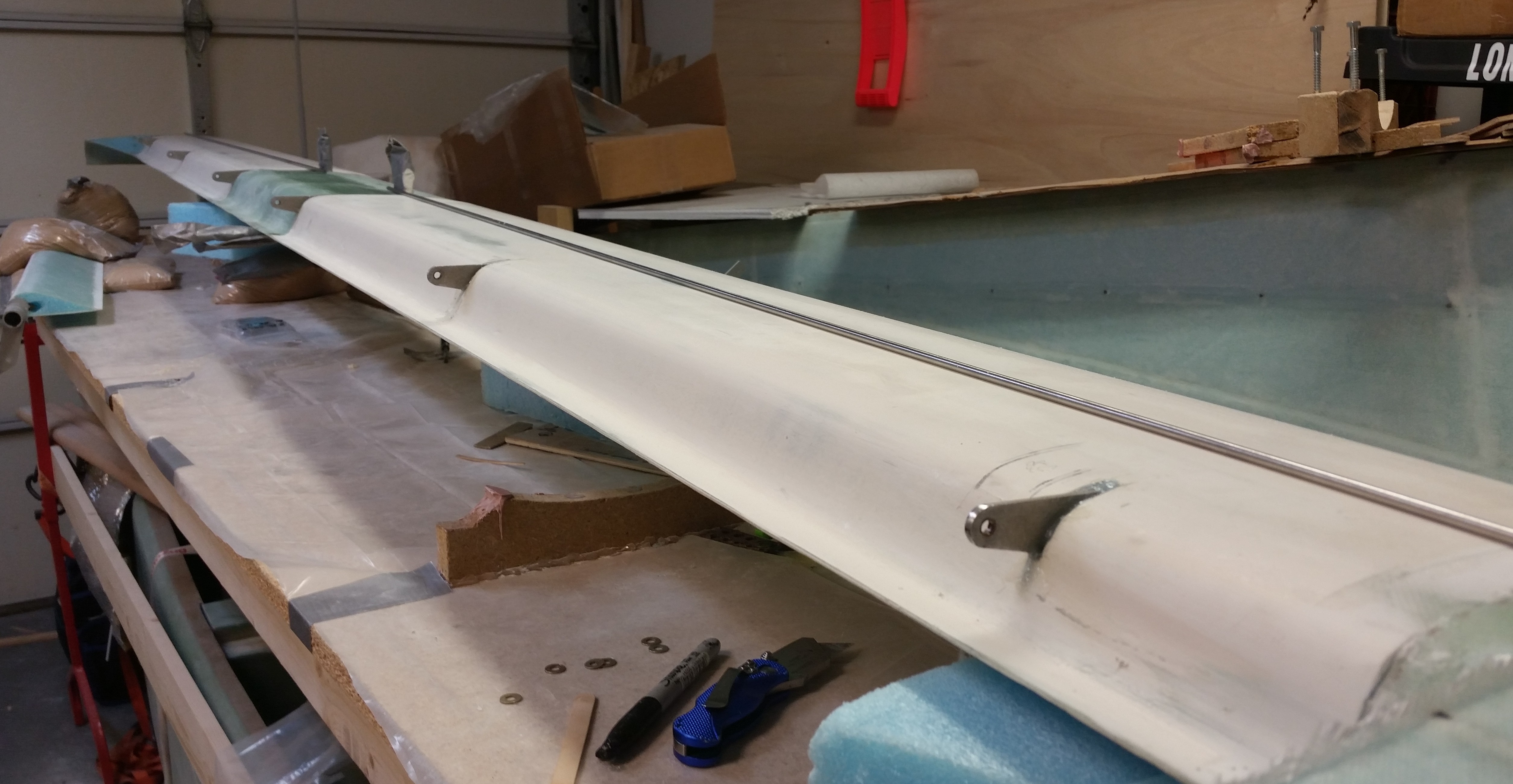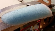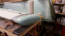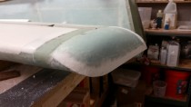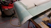
No sanding today . . . sluffing off!

After my meeting at work today, I grabbed lunch on the way home and went over my plans for the dolly I will be building for the fuselage, ala my buddy Mike Beasley.  Since I was close to the final design, I knew that I would actually need to build the base to get enough data to finish this sucker.

First off, why am I doing this now?  (Instead of planting my butt in front of the canard and sanding away . . . ???).  Well, the reasons are: A) To take a break from sanding while still being incredibly productive!, and [more importantly] B) I don’t want to get to a point where I am so frustrated with positioning, repositioning & flipping the ever-weight-increasing fuselage that I work in a less optimized state until then, and then have to take time out to build this thing.  Also, with my buddy’s fuselage incident where it fell off the saw horses & smashed his rear longerons, I figured I would pay the piper up front and get this fuselage dolly knocked out early so I can enjoy its functionality.

Here are the key features and requirements for this thing:

  • Had to be mobile (i.e. on wheels)
  • Had to be low enough when working IN the fuselage & high enough when working ON the external fuselage (adjustable height . . .  more to follow!)
  • Had be able to be leveled as a surface–not shimming the actual item, but leveling the platform itself. (Leveling screws . . . aka, poor man’s outriggers)
  • Secure canopy storage (since I would have the length and width, I might as well make the underneath area useful and store the canopy in a wood box)
  • Optimized stabilization of the fuselage (when the fuselage gets its nose, etc. more weight will be added and more awkwardness in controlling it will ensue, thus multiple tie down points are a must)

So, while sitting having lunch 2 blocks from Lowe’s, I realized that I had met all my critical design goals and I could begin construction immediately.  I bought a couple of sheets of flooring material (OSB) and a few 2x4s to get me started.  While checking out the cashier asked me if it started raining yet!  So with that info in hand I rushed to get to the house and get some wood cut.  It did sprinkle on me quite a bit, but never got into an actual downpour, thank goodness.

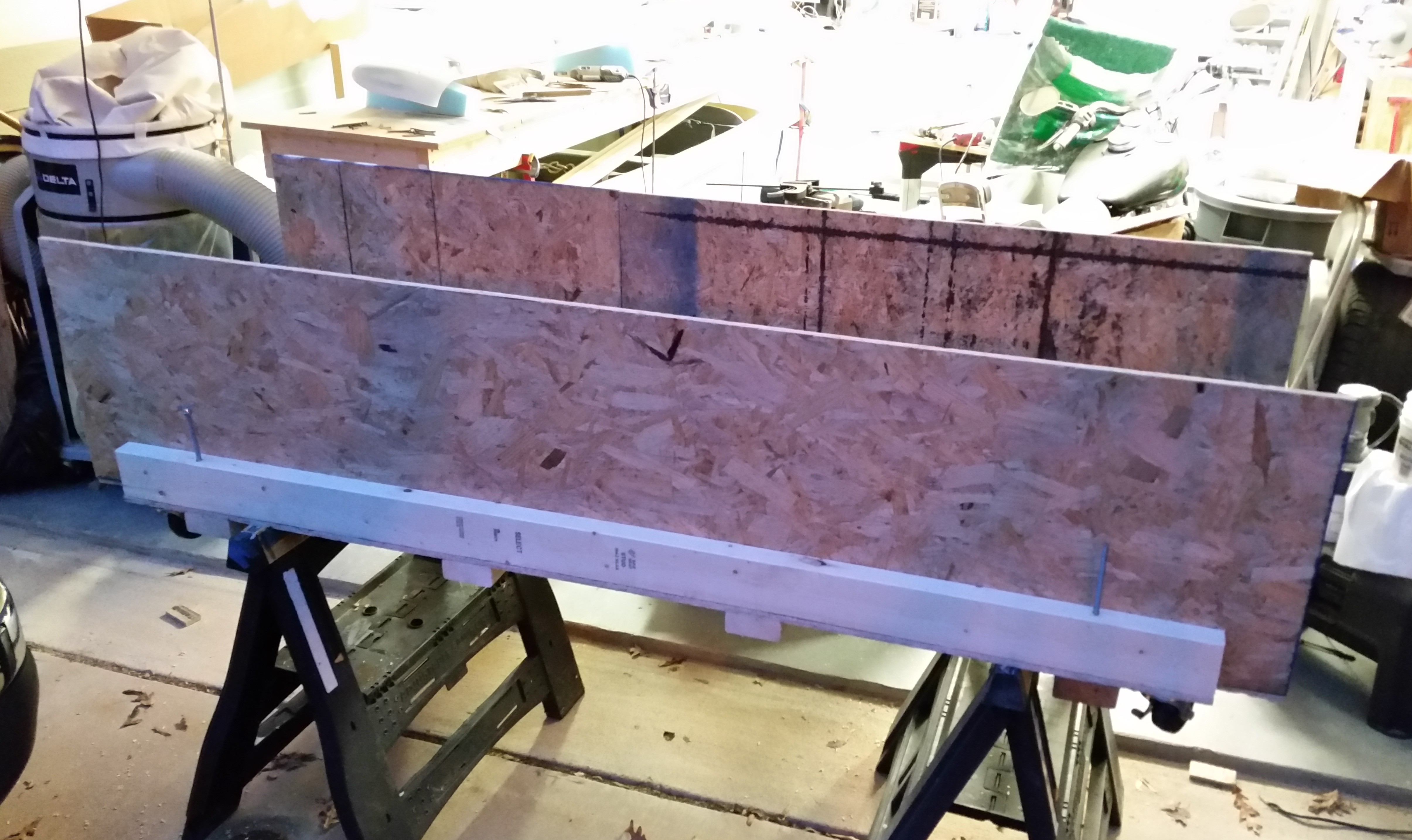
After cutting the wood, I started constructing the base of the fuselage dolly.  Here’s the very bottom of the dolly.  I’m about to attach 4 each 2×4 cross beams & the wheels to the bottom of this thing.
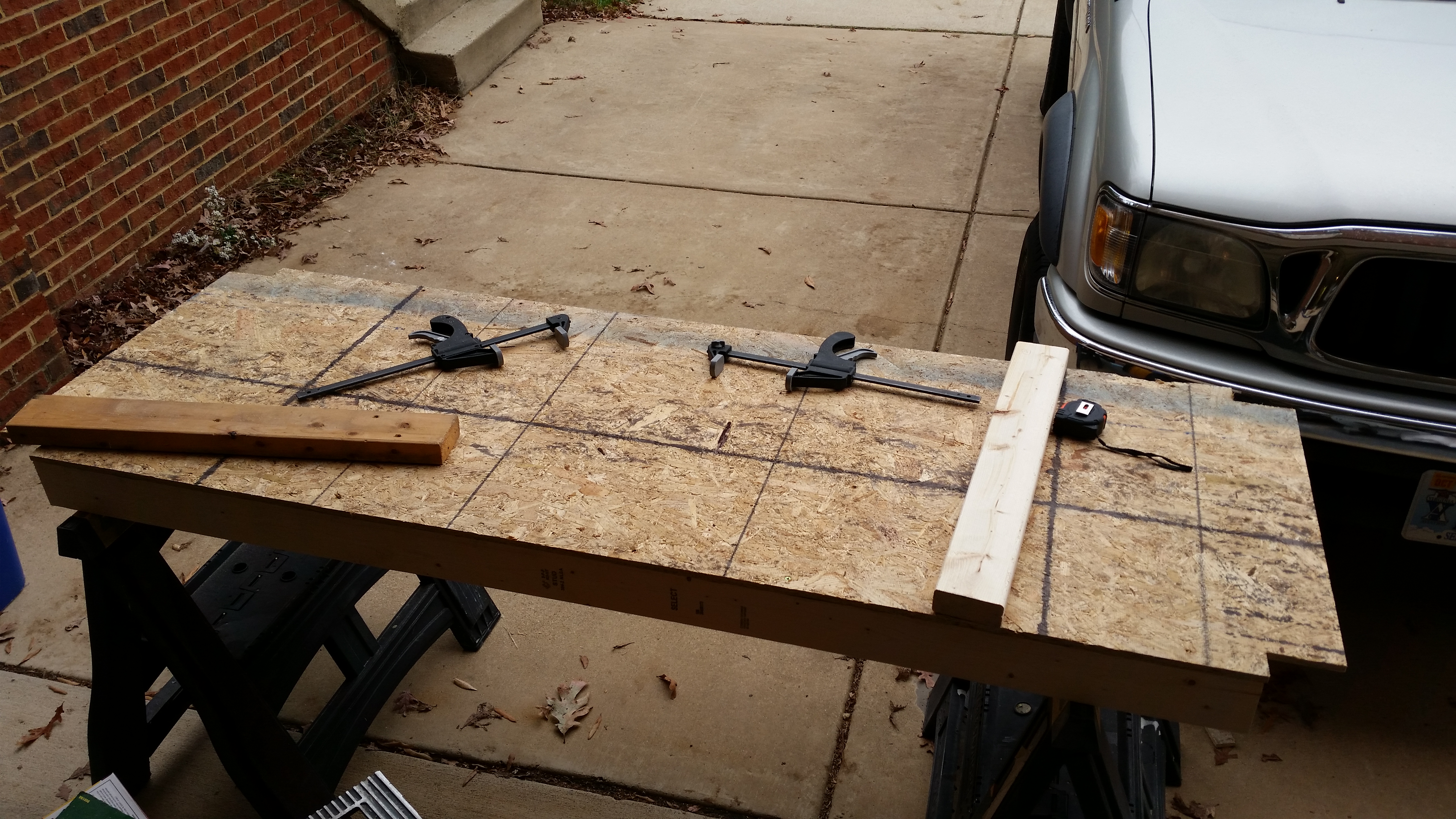
Bottom of fuselage dolly base

Here’s the base turned upright.  If you look closely you can see the wheels near the corners (mobile) and the four threaded leveling screws just inboard of each corner as well.
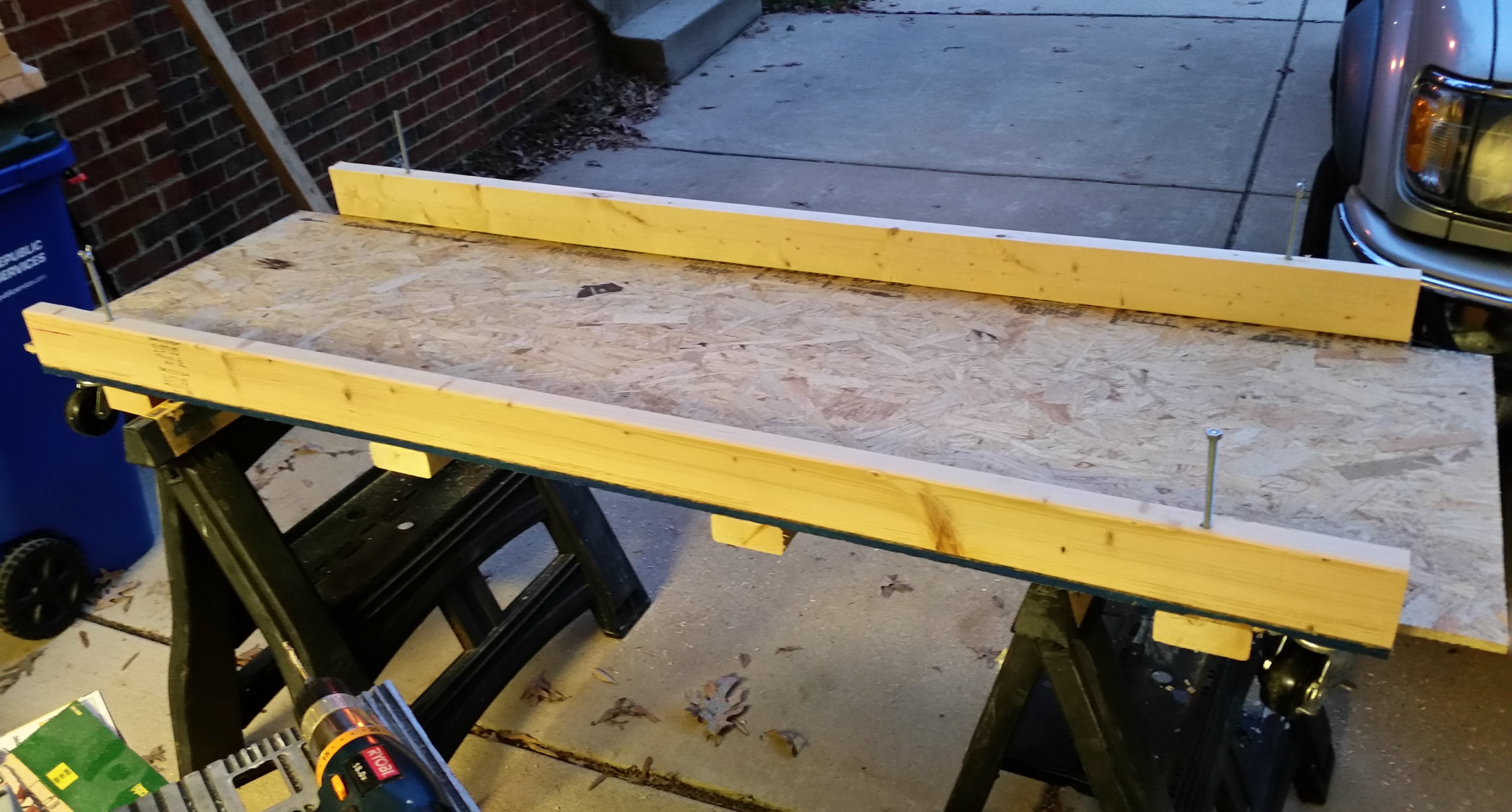
Top of fuselage dolly base

Here are the OSB sides attached.

Side walls added to fuselage dolly

And the future temporary home of the canopy.
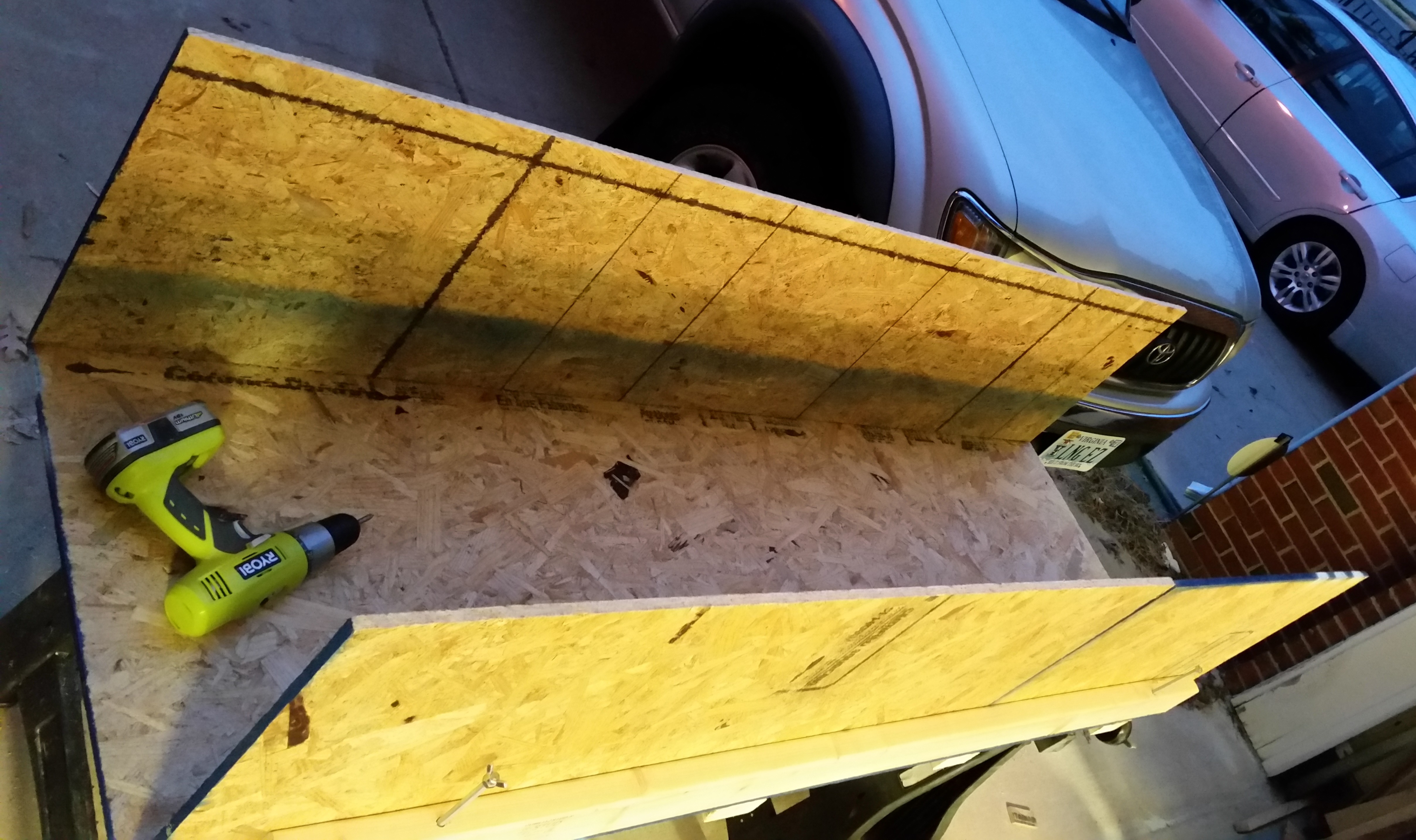
Canopy storage area

I added the top cross joists that sit on a 2×3 stringer that runs the whole length of the dolly on each side.
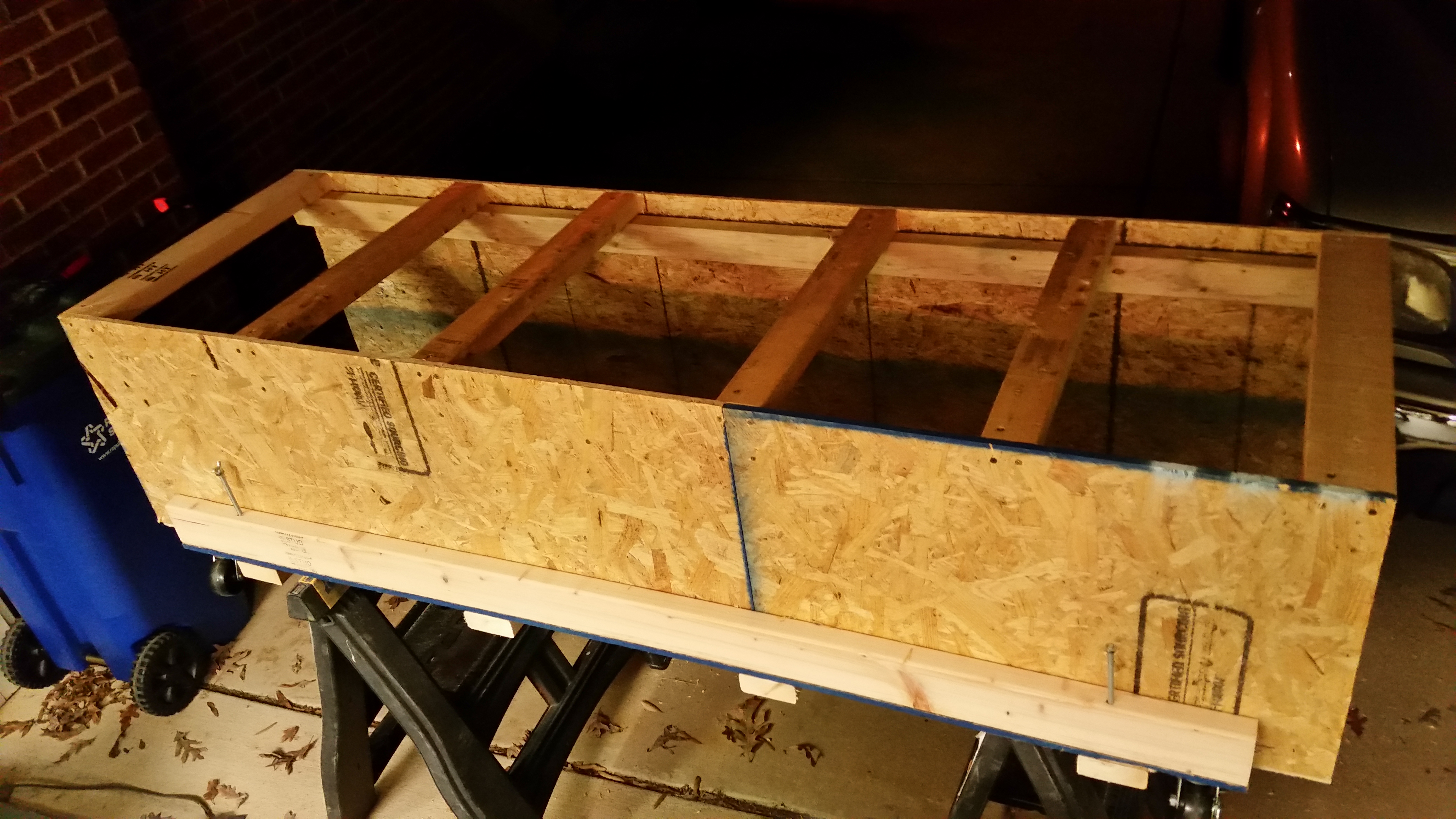
Top cross beams - fuselage dolly

After getting to the point where I needed to cut more wood, and for some parts buy the wood to cut it, and get some more hardware, I cleaned up my work area and stowed my new creation up on end.
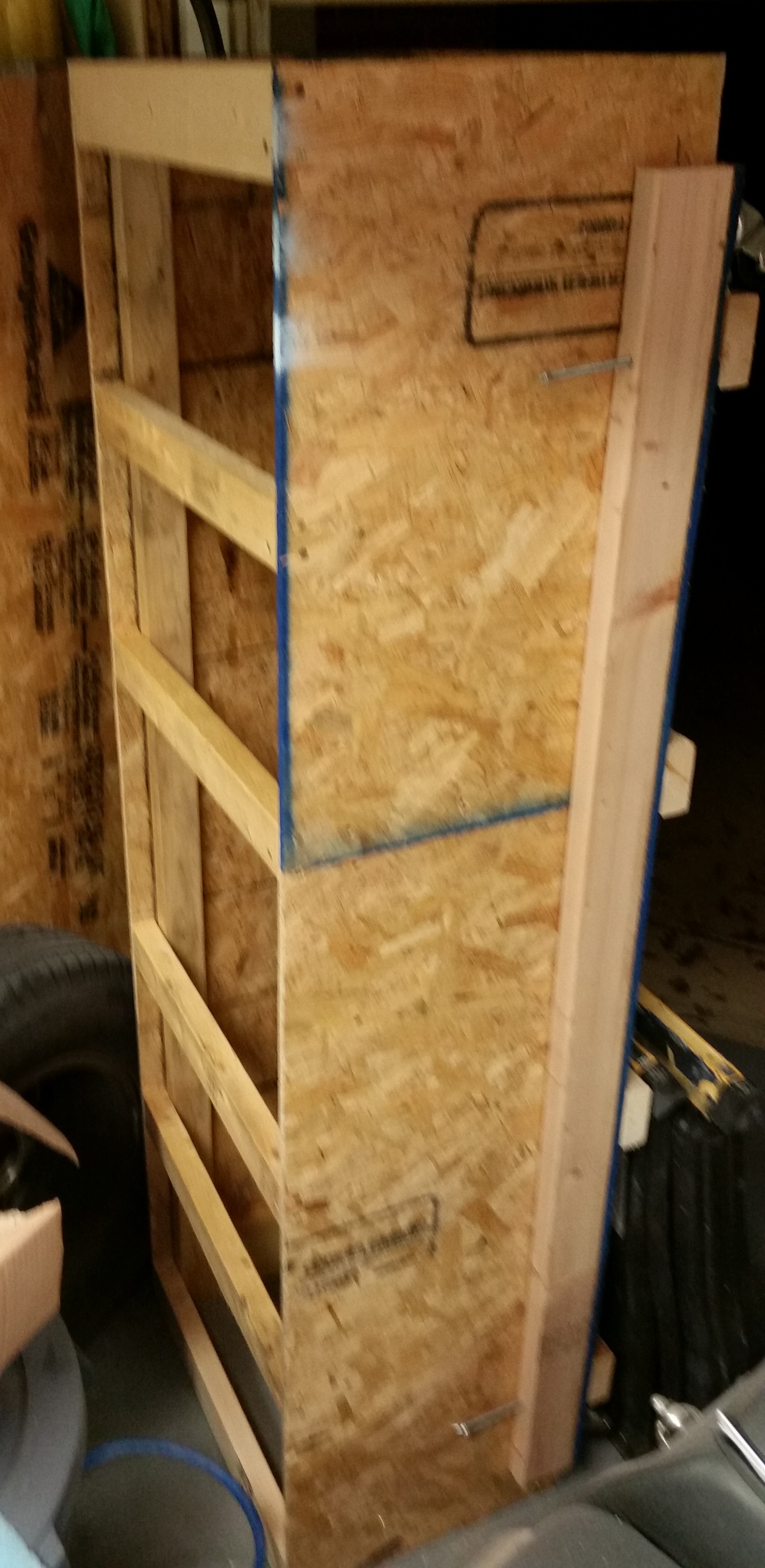
Temp storage of fuselage dolly

I then ran off to Harbor Freight to pick up some “supplies” . . . mission operational security does not allow me to divulge any information until later, after it’s been implemented and tested.  ha!

Upon returning home I sat down to fix a design flaw in the Nose Gear Actuator wiring before it became a problem.  There is a small electrical component (diode? capacitor?) that was soldered in the wiring line with one of its two tiny legs soldered to a wire on each side.  If you look at the second pic you can see daylight between the component and the wiring bundle.

Now, my Long-EZ building buddy, Capt Meatballs, pointed this out to me after his broke and he had to find it via troubleshooting.  The connection legs were so fine, that when the one side broke he had to buy an entire new component & solder back into place to fix it.
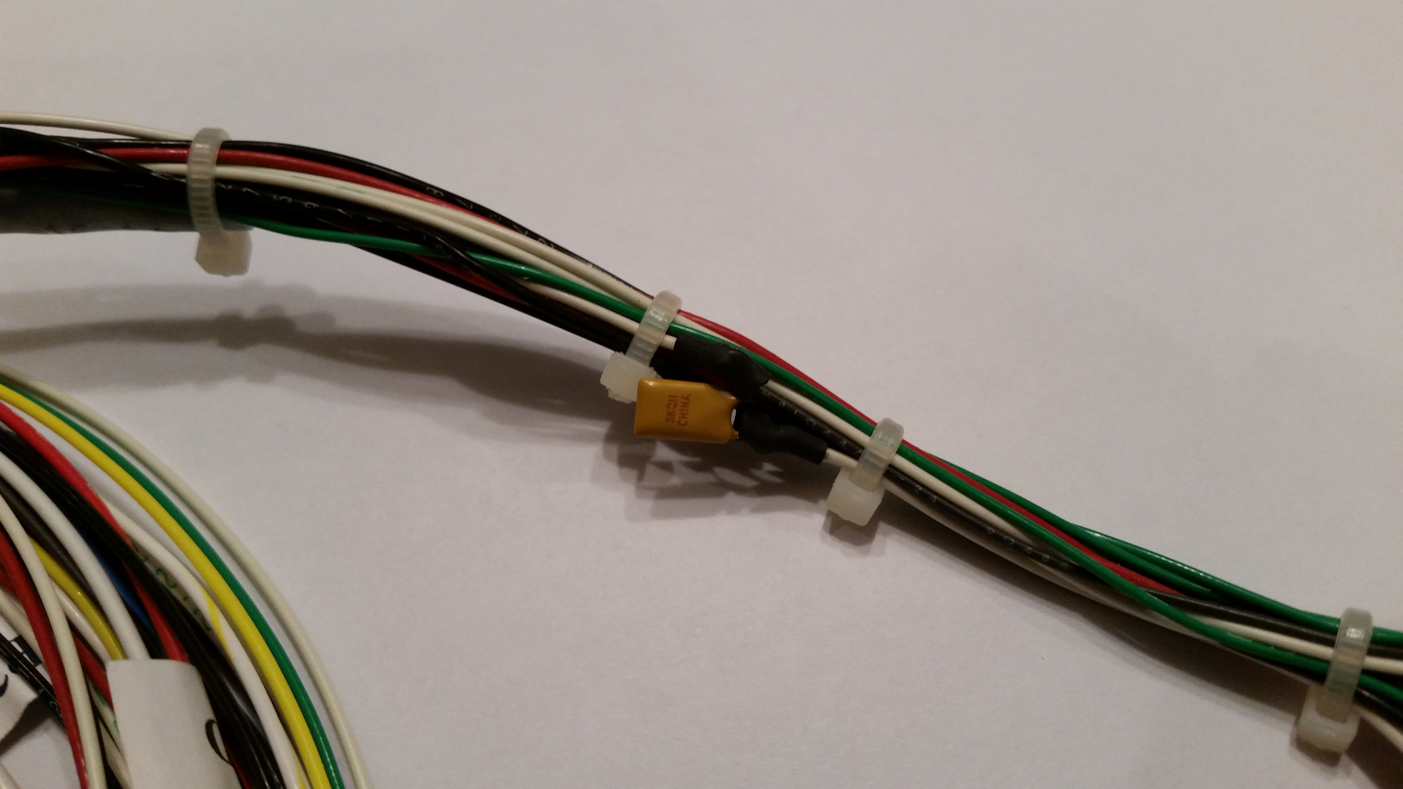
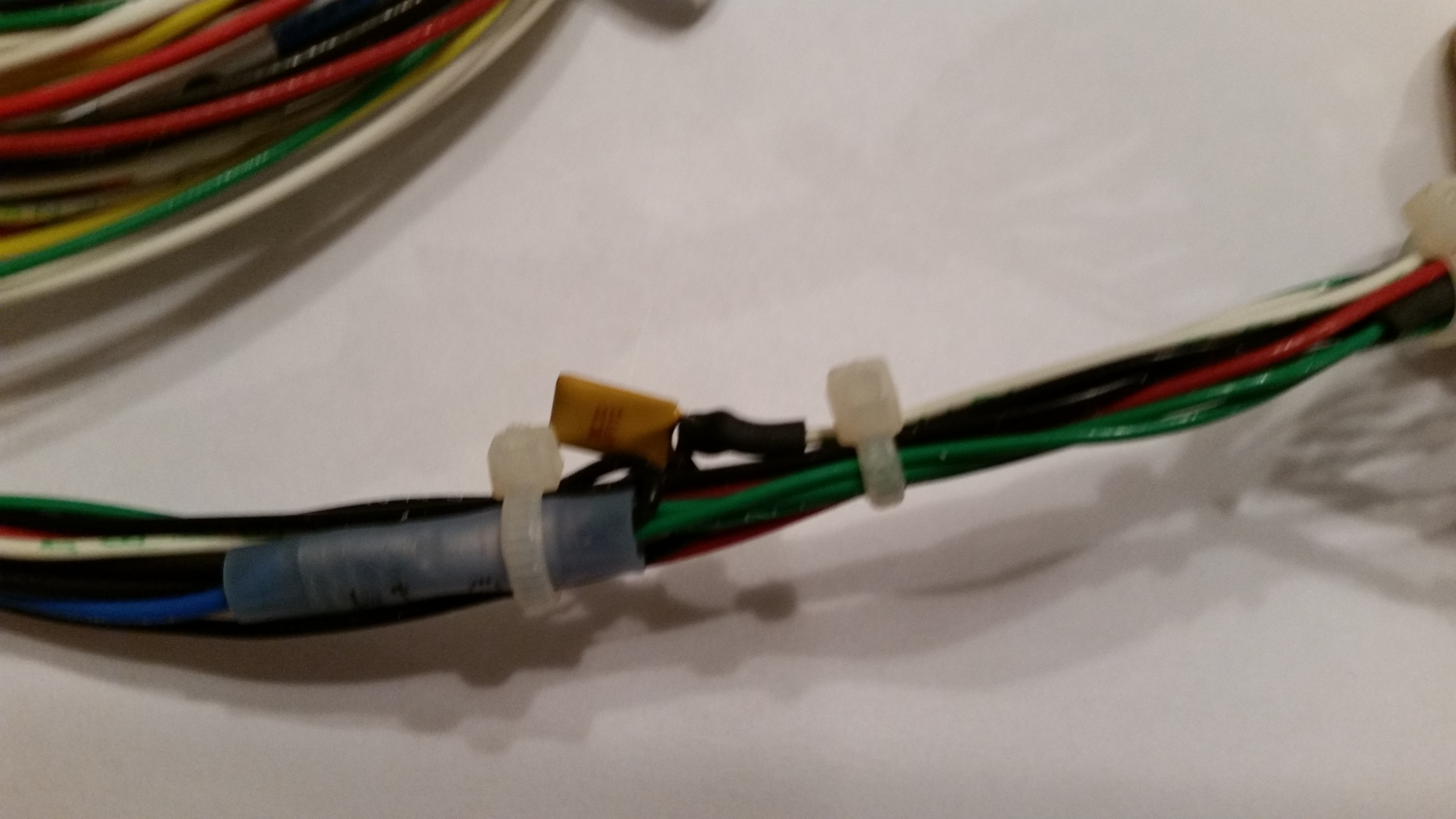
Electric gear actuator preventive maintenance

Potential for mechanical failure

To avoid this issue I employed the “poor man’s electrical potting material” solution to this situation.  I took electrical tape that I had folded over a couple of times and wedged it underneath the suspended wire legs on each side to secure them from any pressure coming through the tape and still snapping off one or both of the legs.  I then wrapped the whole assembly in electrical tape.  May not be the prettiest fix, but with a big clump of relays just down the line I wasn’t able to get some tubing shrink wrap over it.  So this fix will have to suffice!
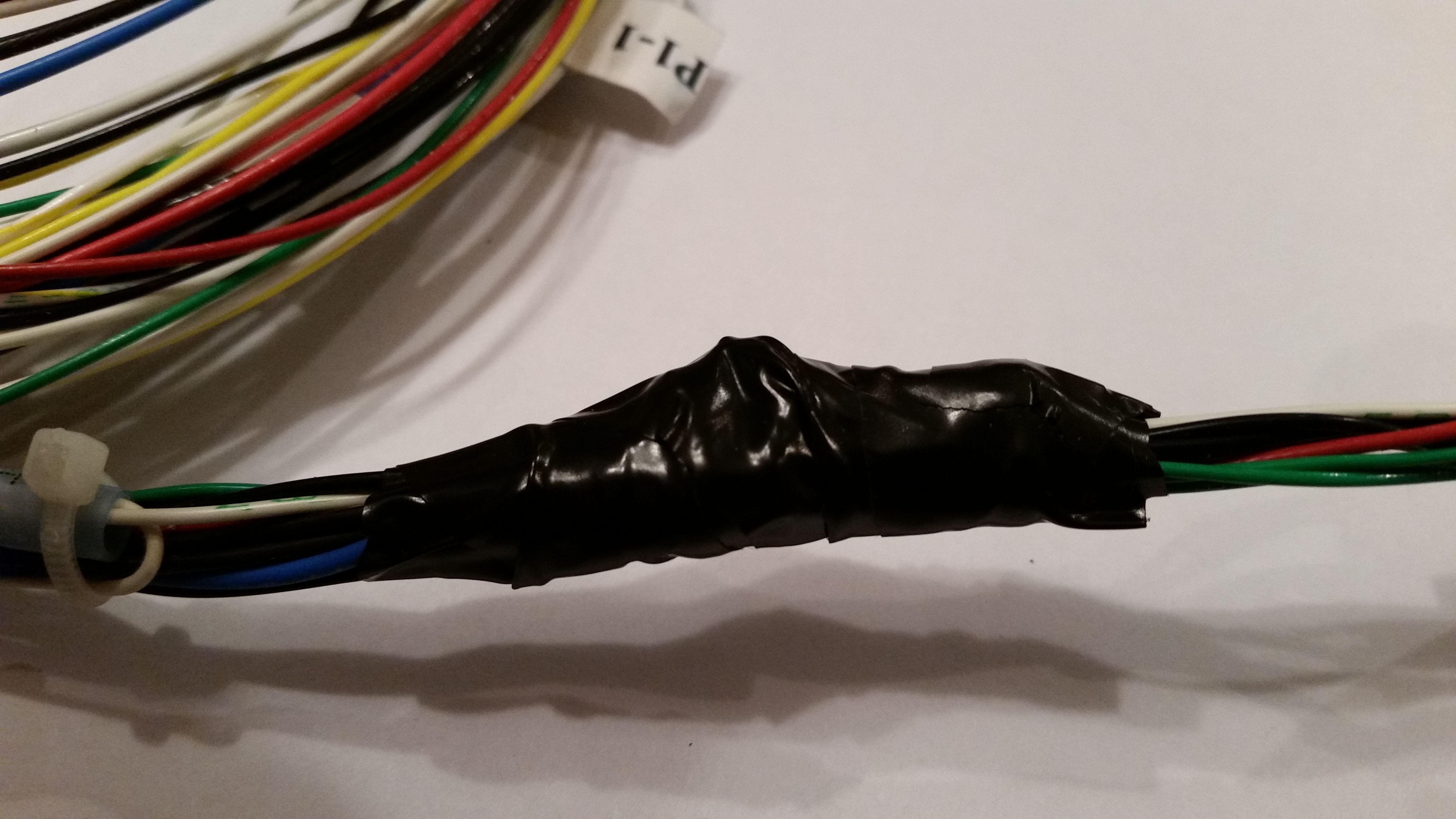
Poor man's potting material!Poor man's potting material!

Now that I have the base of the fuselage dolly built, I’ll start incorporating it into the build schedule.  Thus, while any part, epoxy, or primer is curing I’ll take a few moments to get this dolly built.  My plan is that when I start in seriously on the nose & nose gear that I’ll have this fuselage dolly underneath the fuselage and ready to go.


Chapter 10 is Complete!

Yes, my dear friends, I’m calling the canard complete!

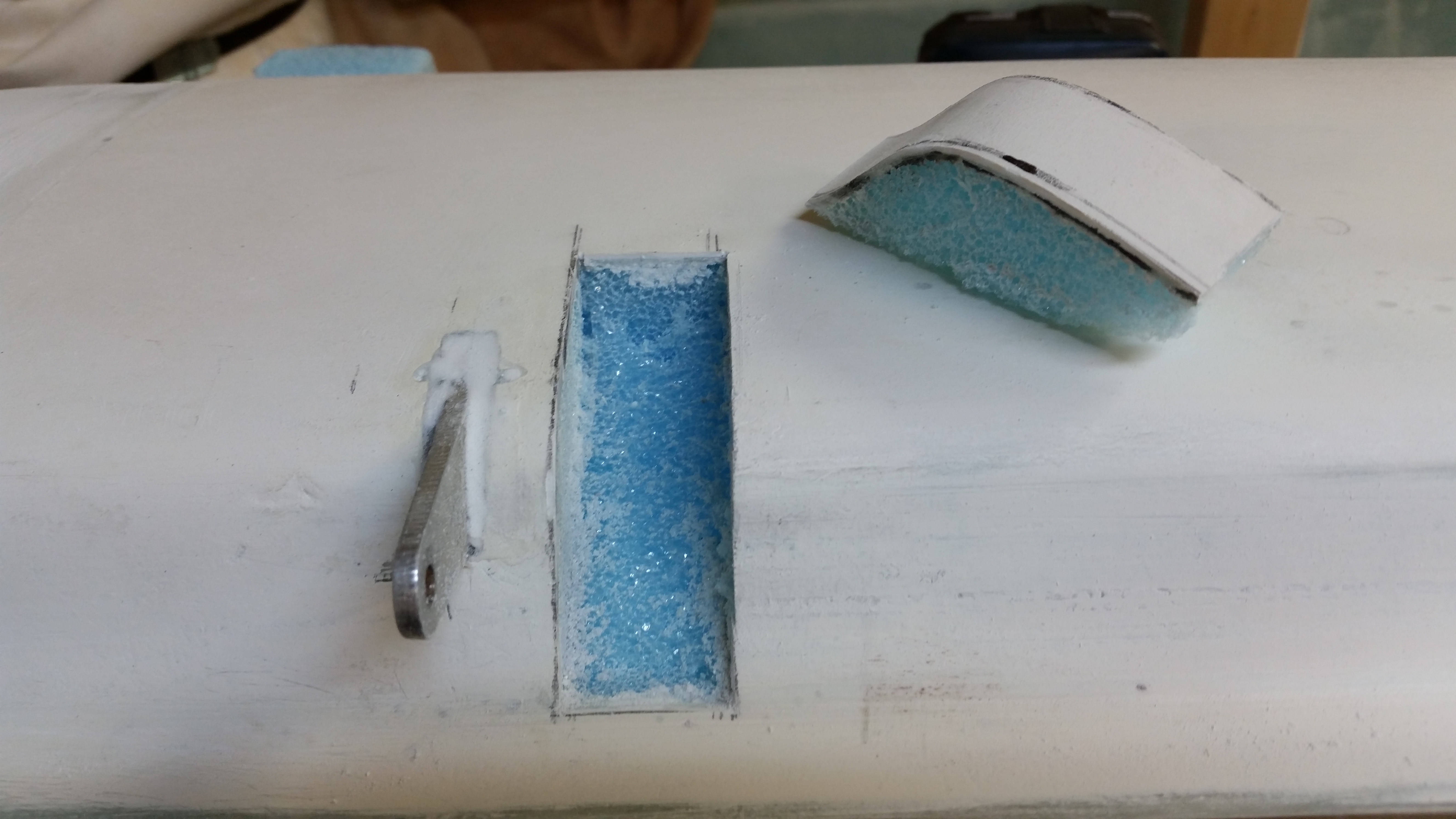
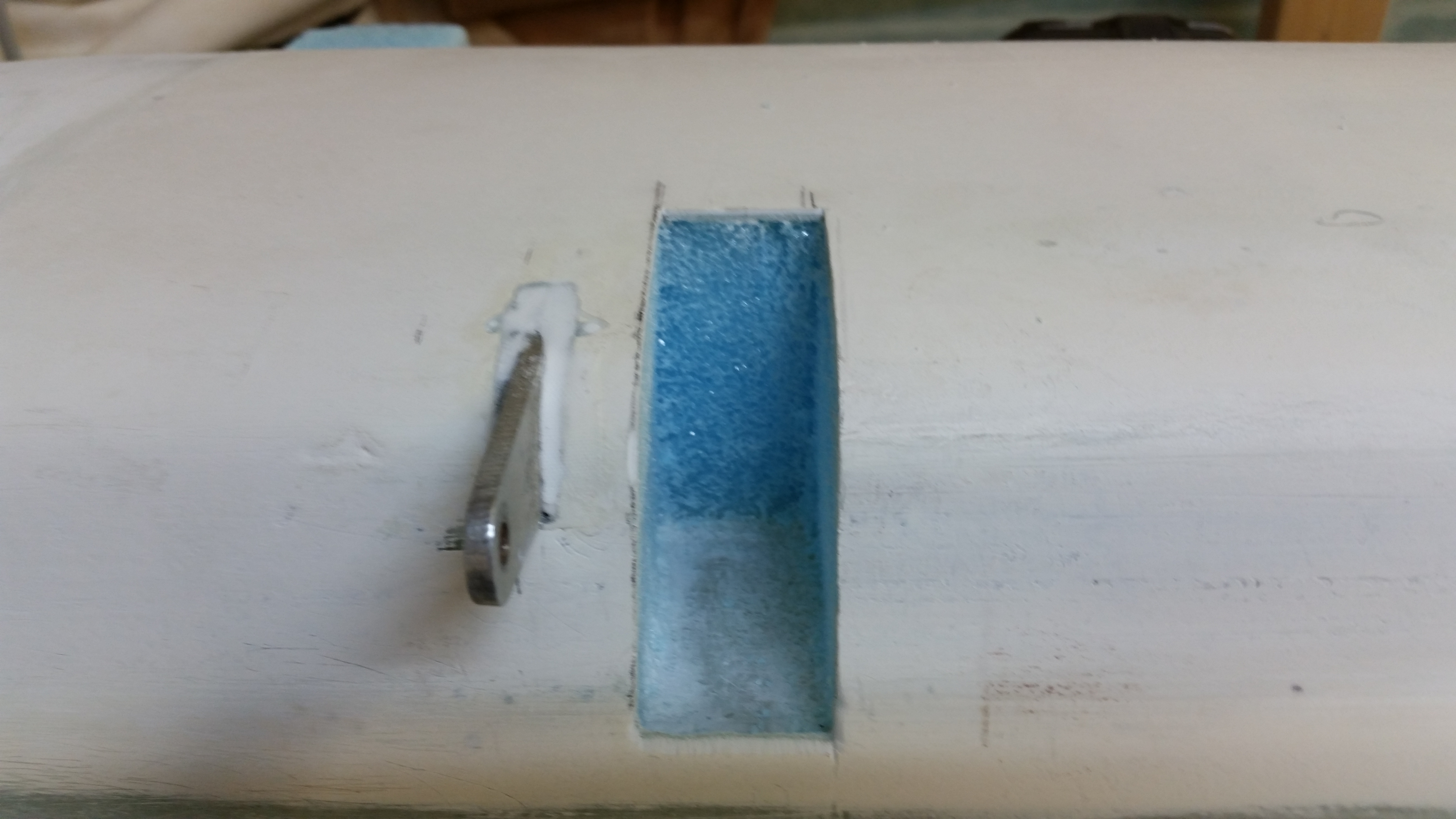
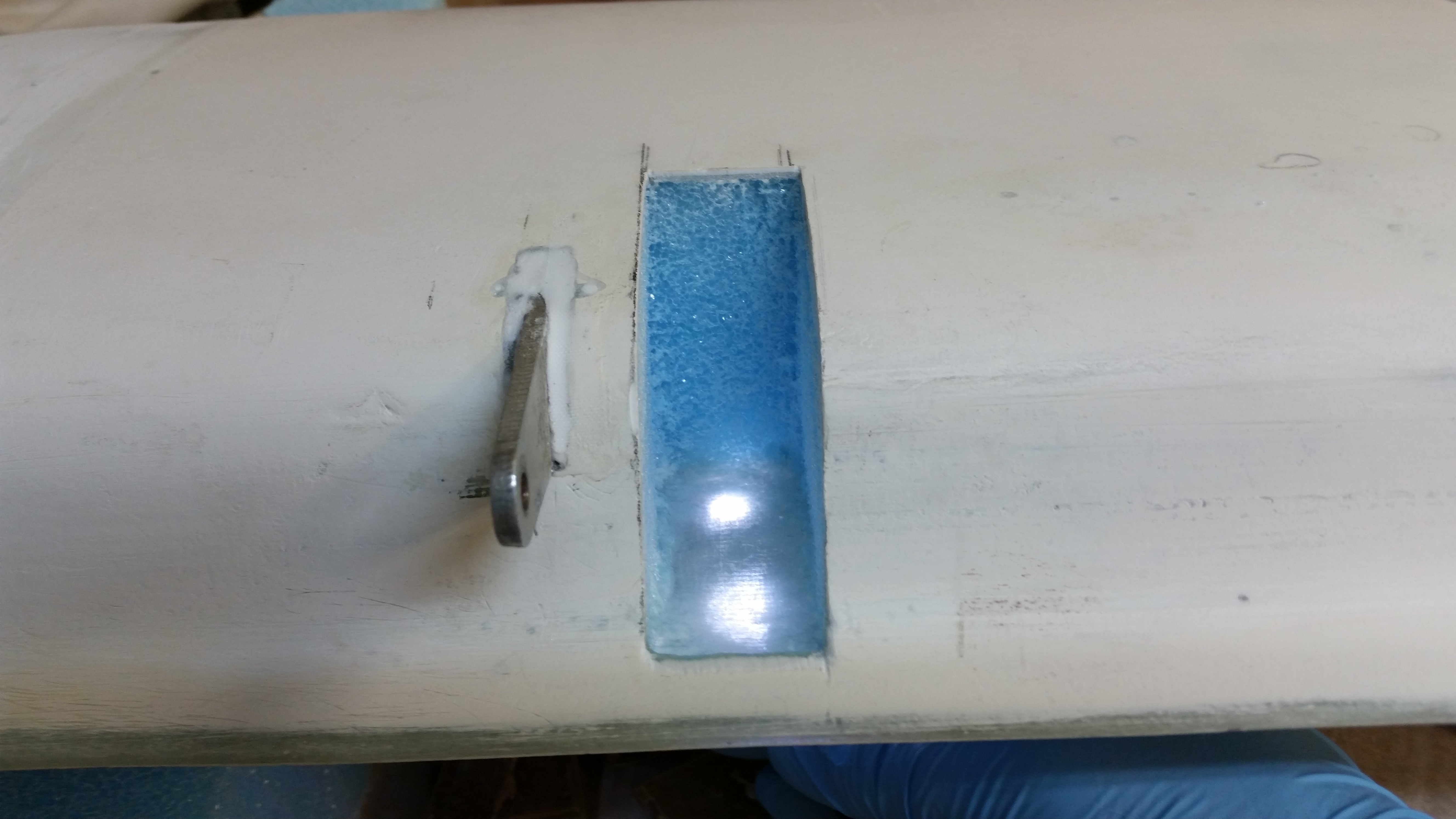
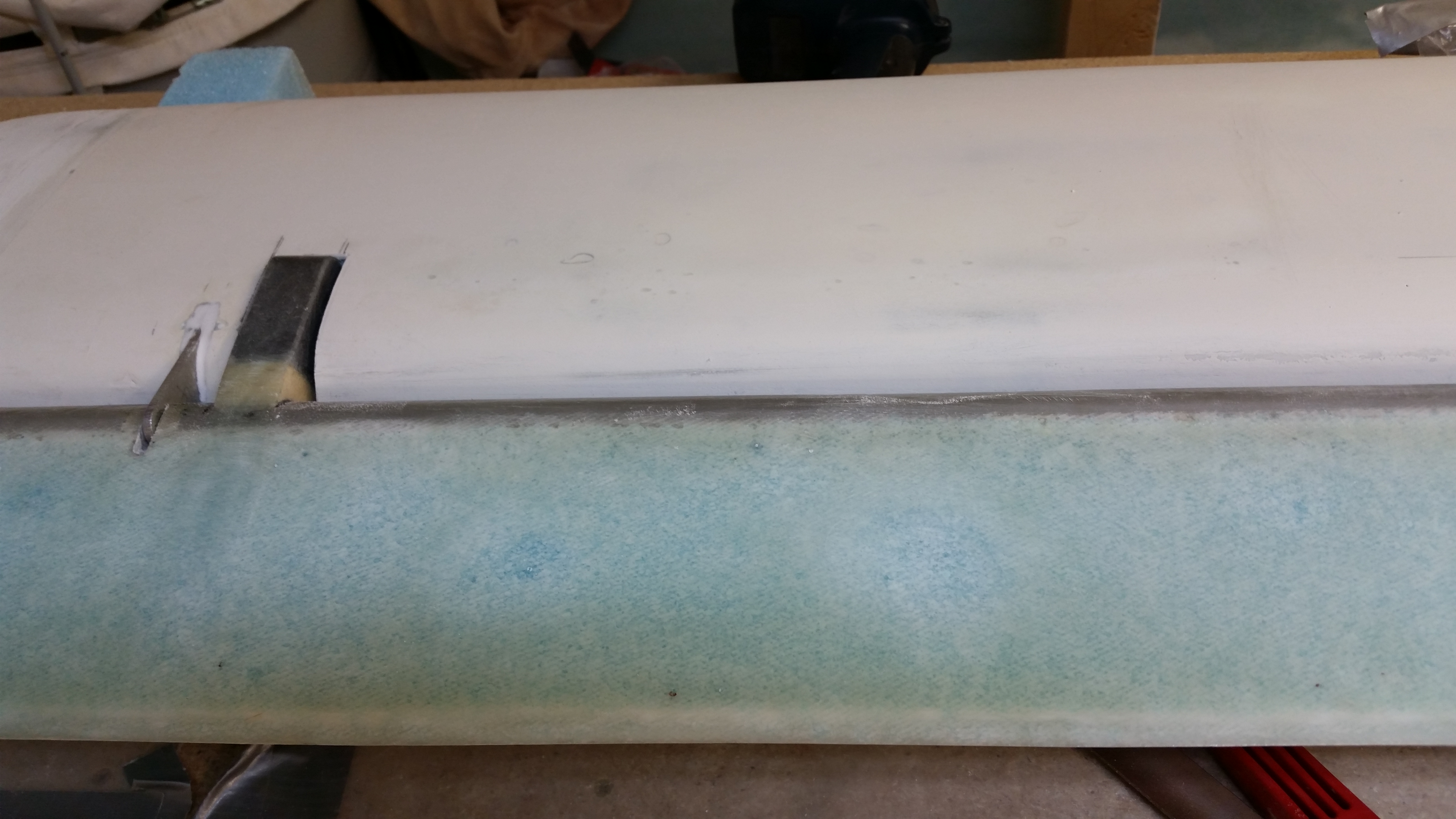
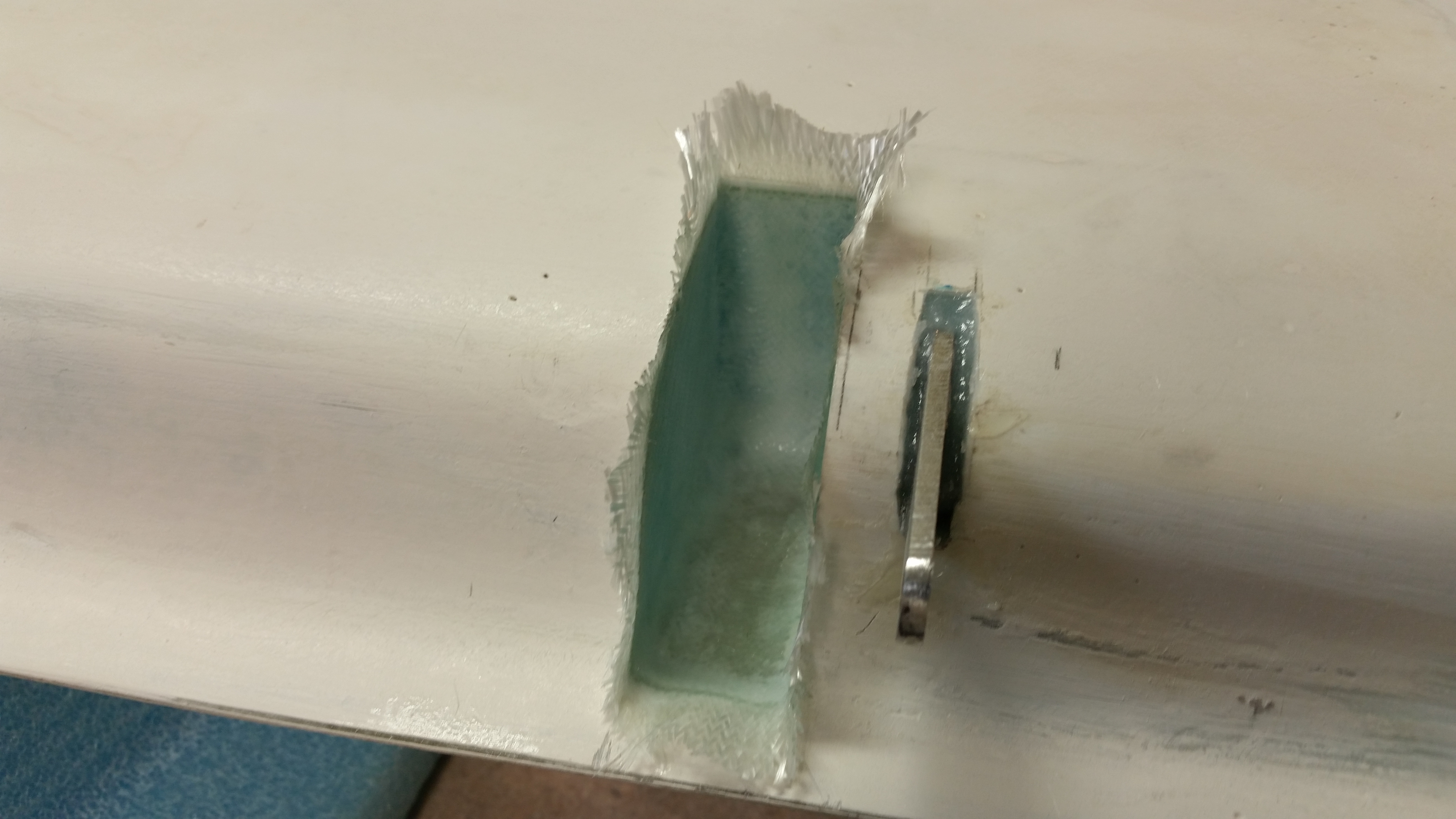
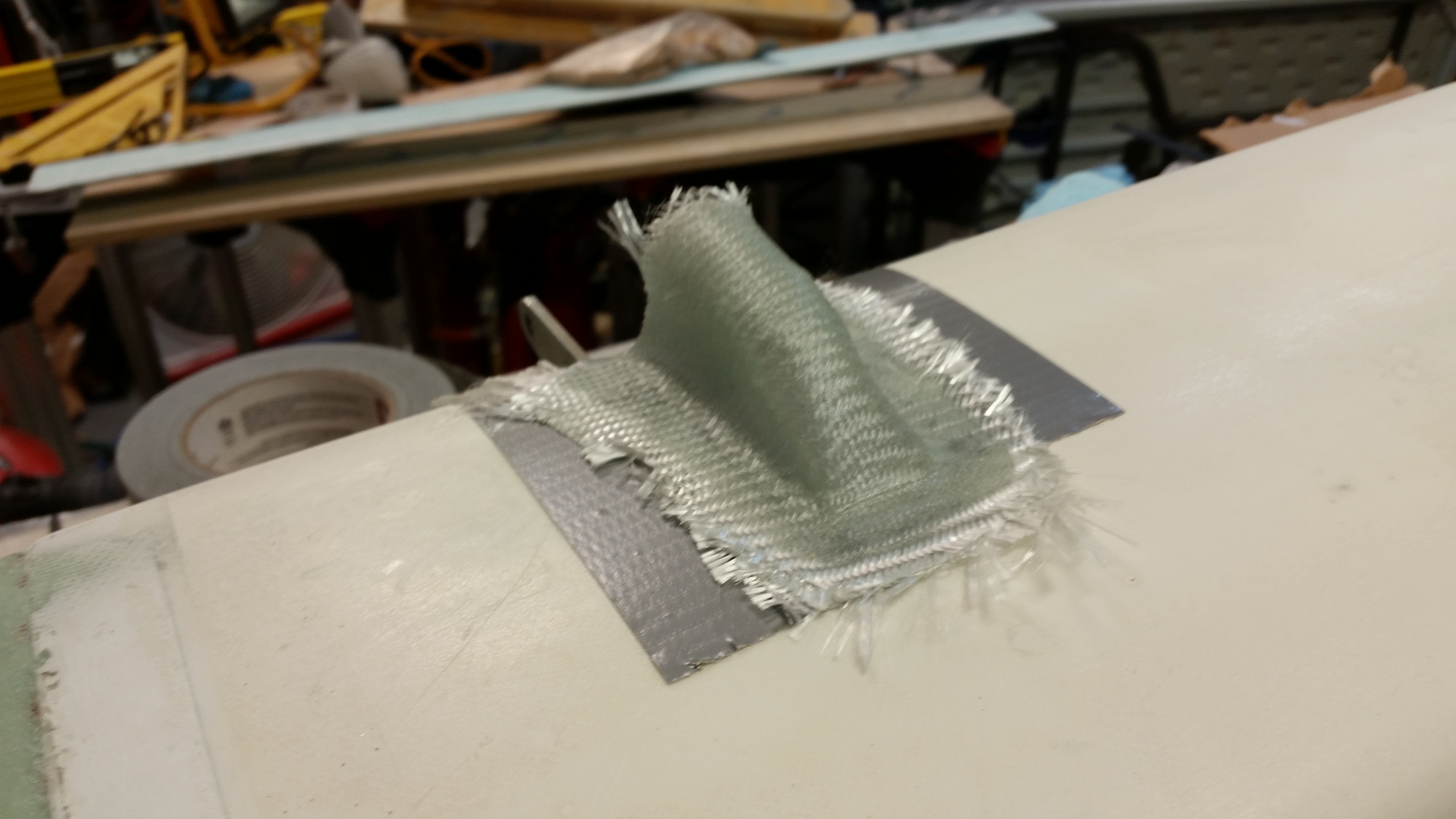
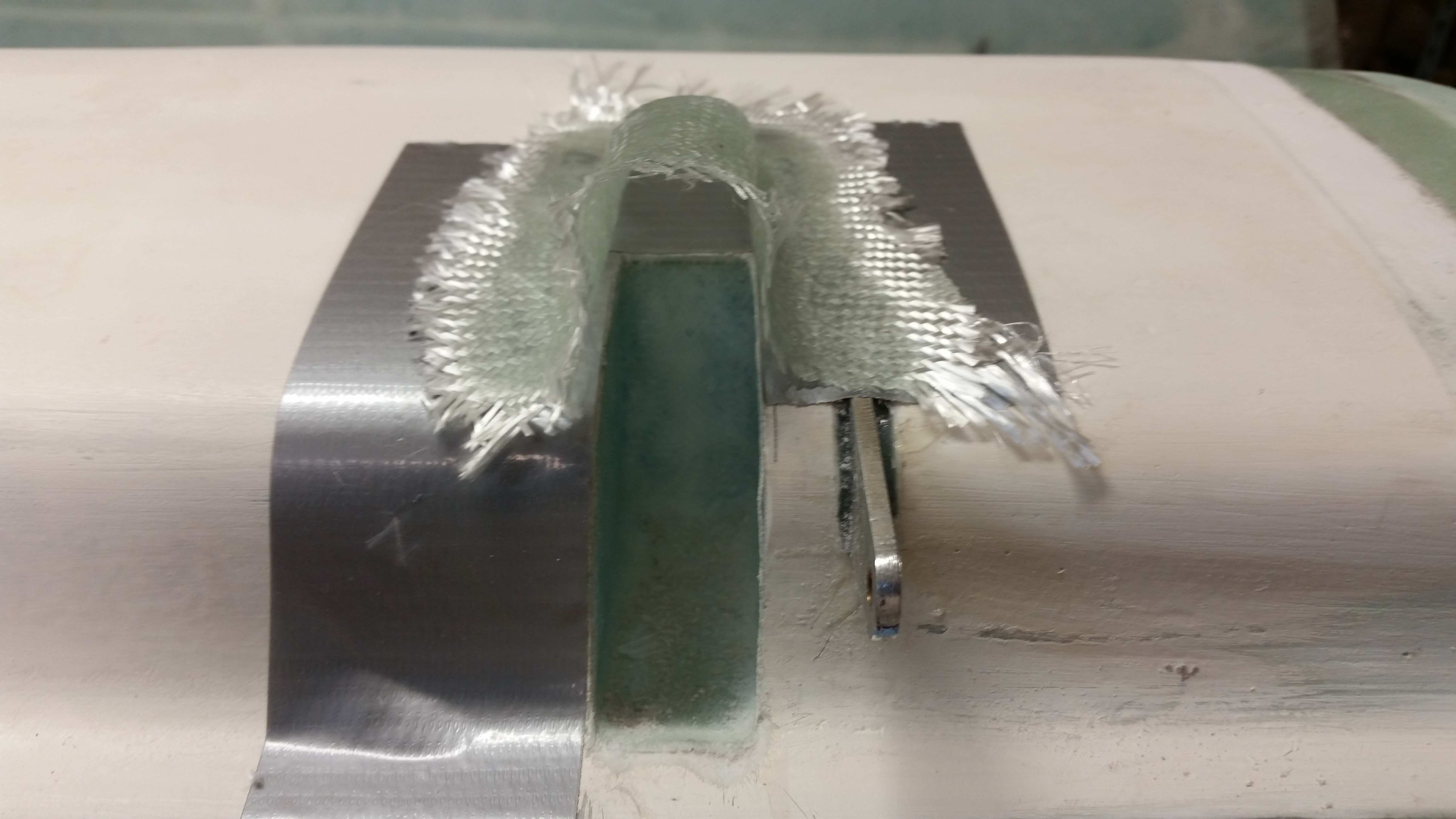
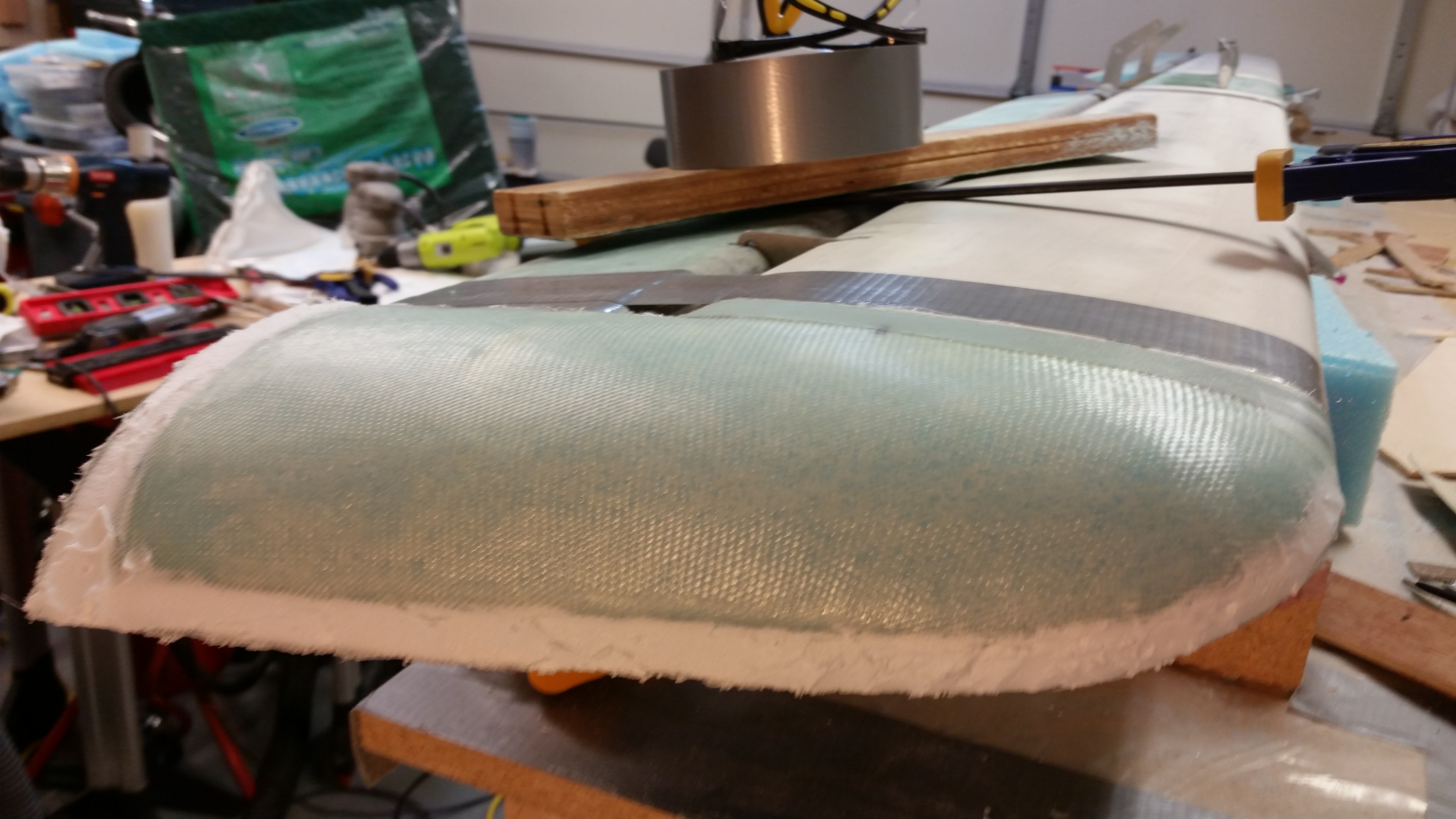
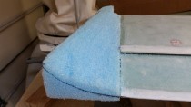
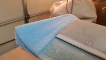
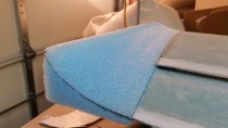
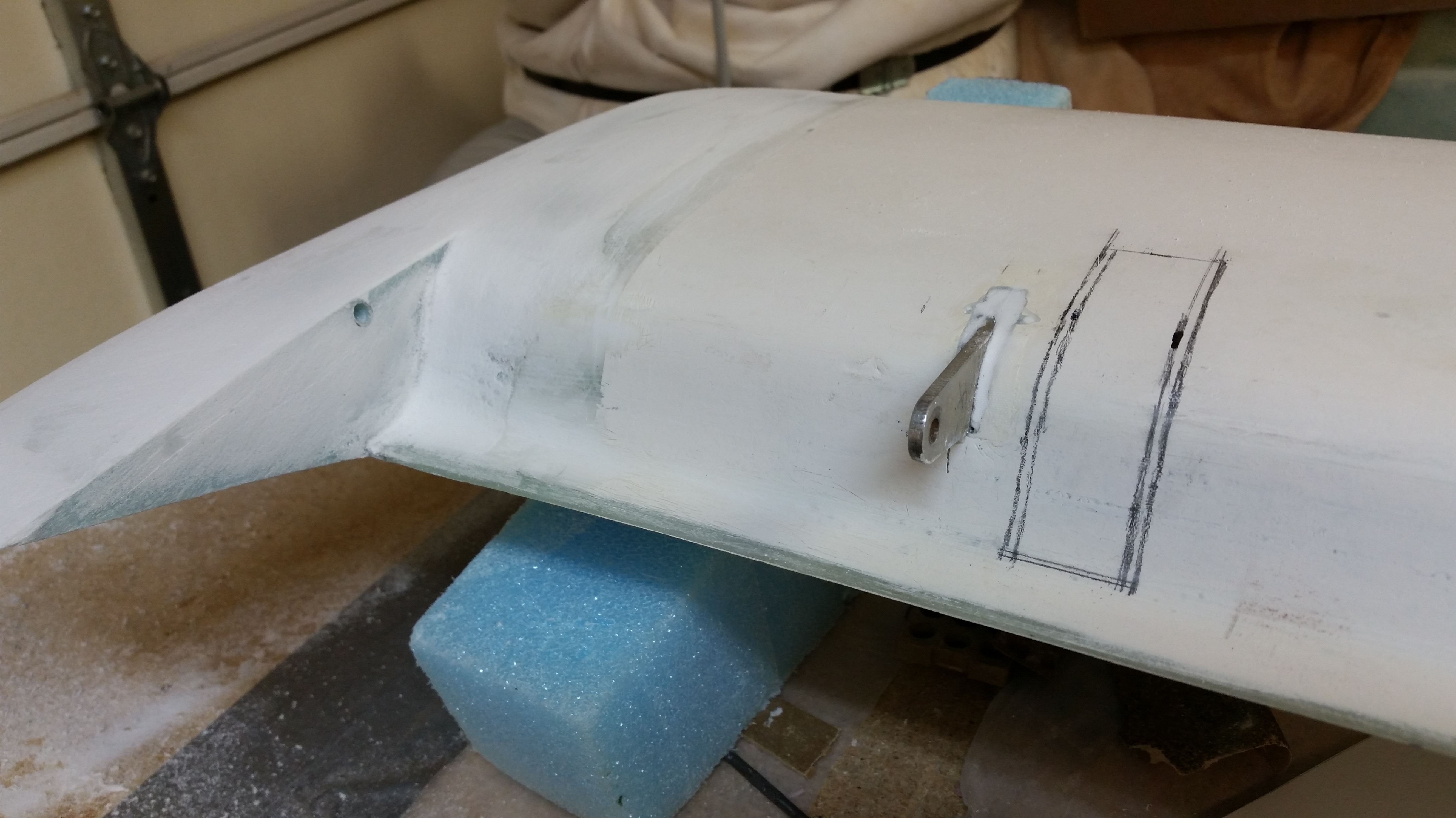
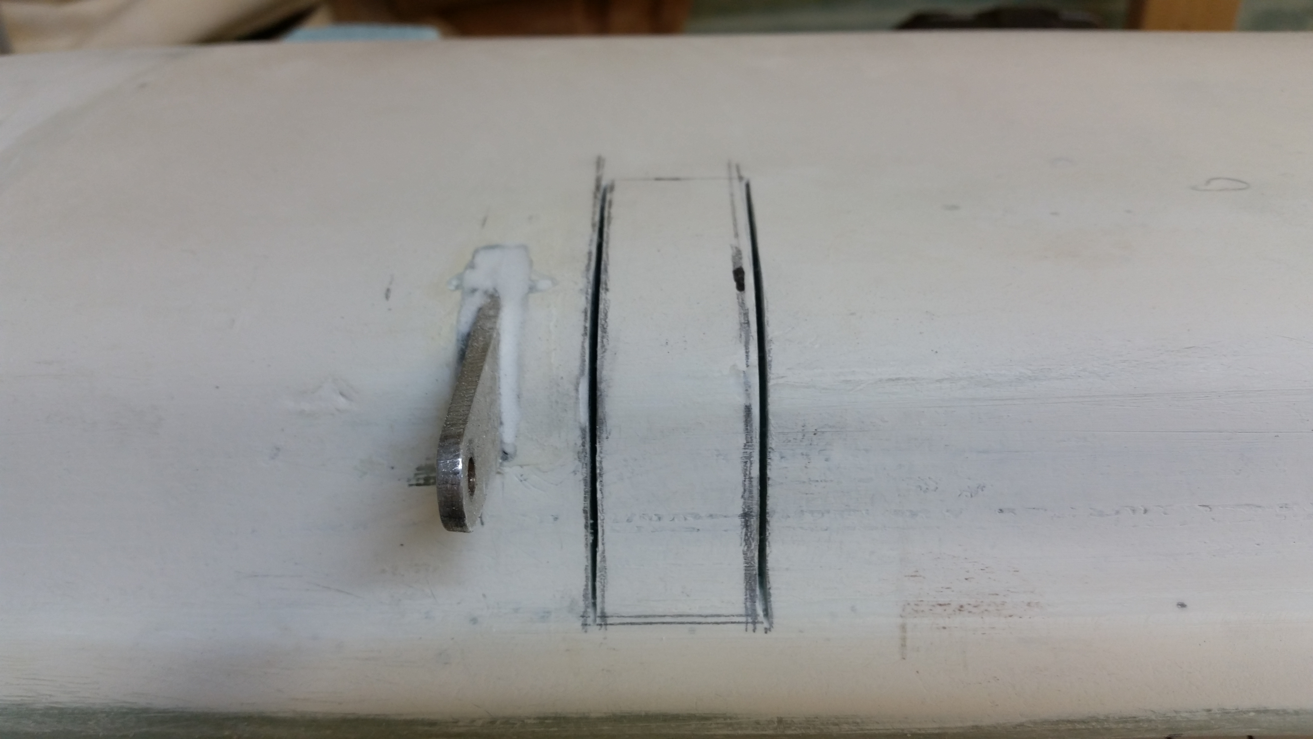
I started off today by cutting out the right elevator weight notch in the canard.

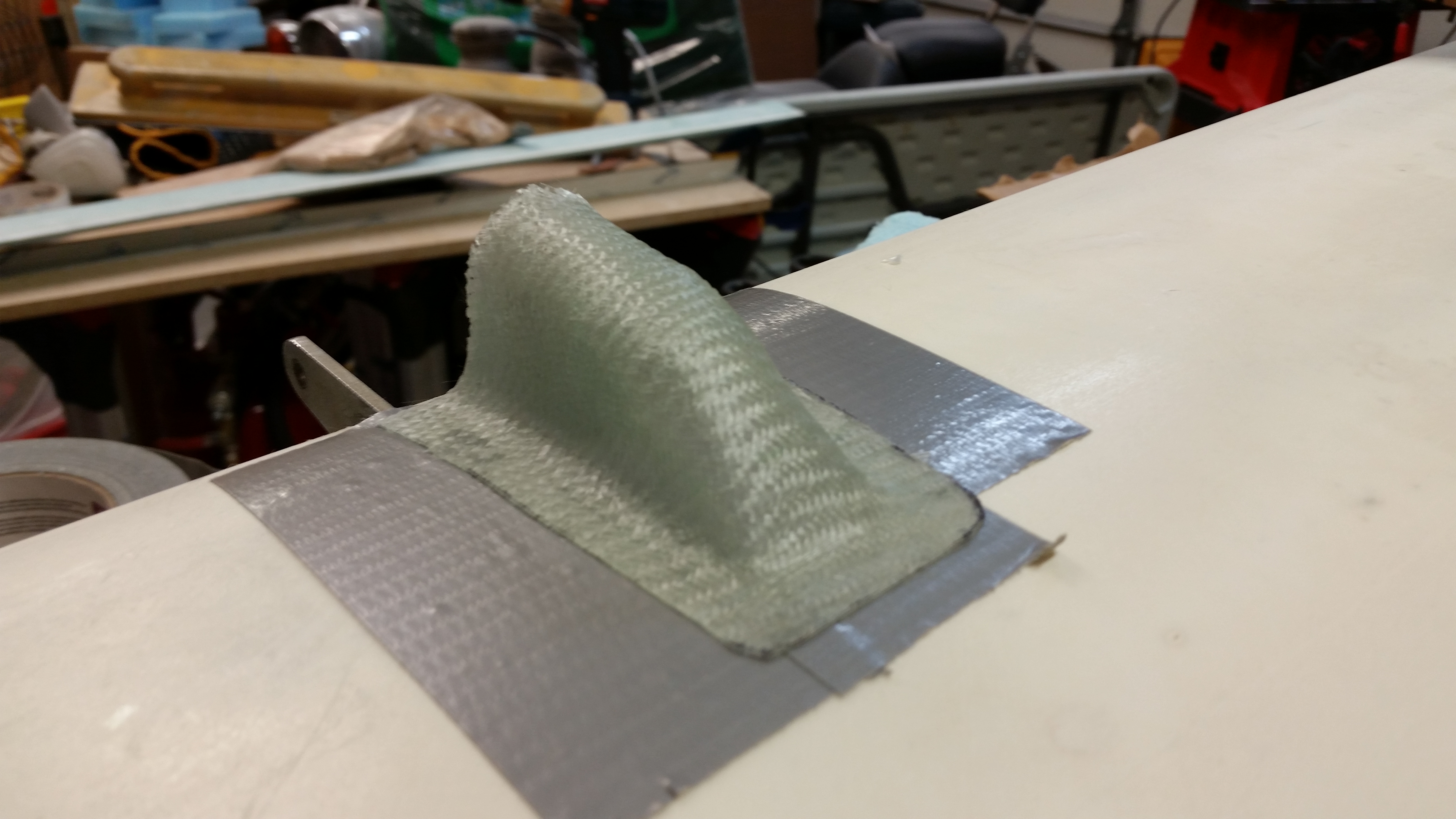
Elevator weight notchElevator weight notchElevator weight notchElevator weight notch

Here I’m checking the opacity of the glass beneath  . . . ha!

Checking glass opacity . . . ha!

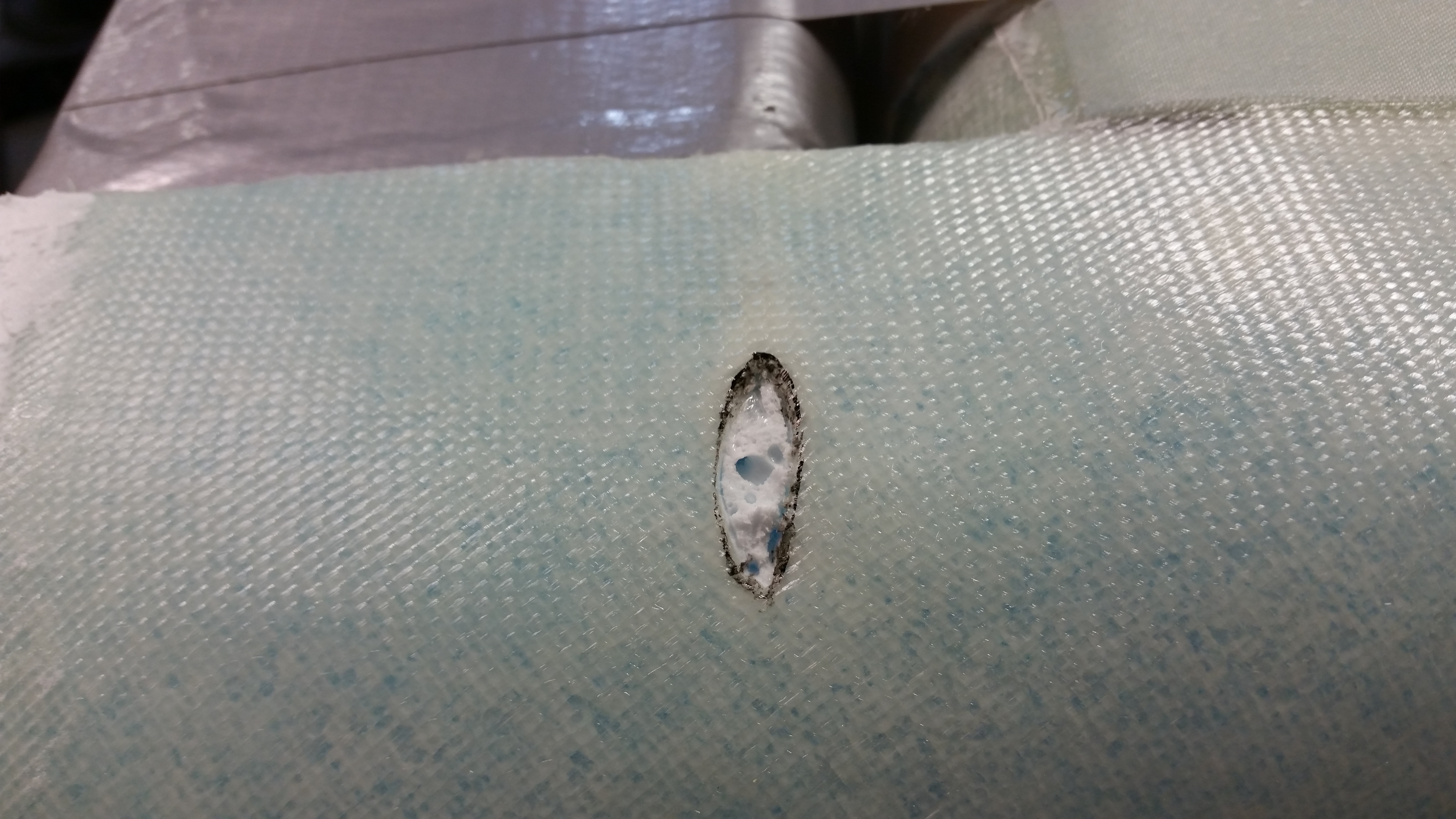
I measured everything out using the right elevator as a template and then got to work on micro’ing the sides and laying up 1-ply of BID to protect the foam.

Using "bad"elevator for template

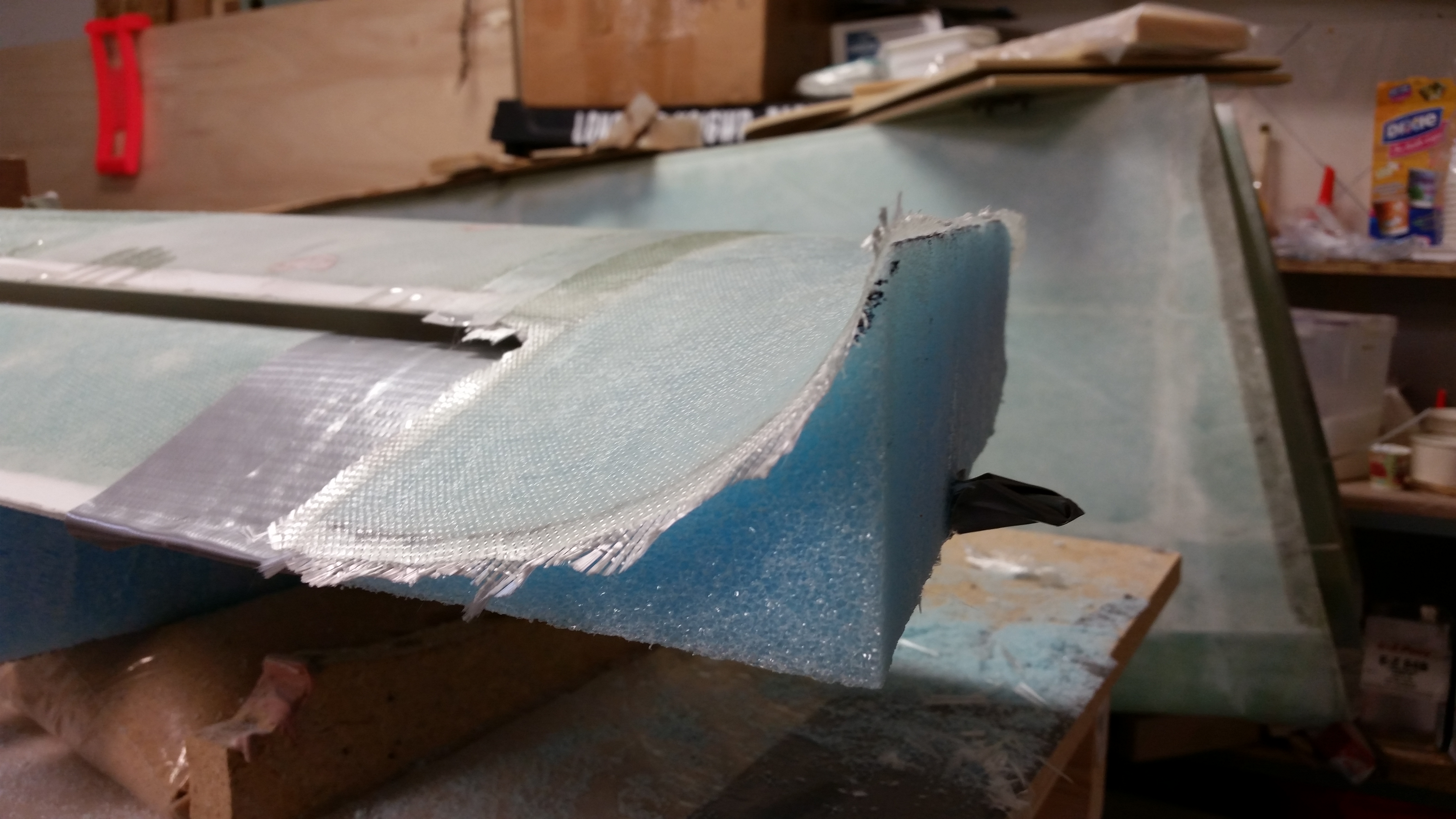
BTW, here’s the left side still in the same state I left it in after last night’s cheese grating.

Elevator weight notch cheese grated

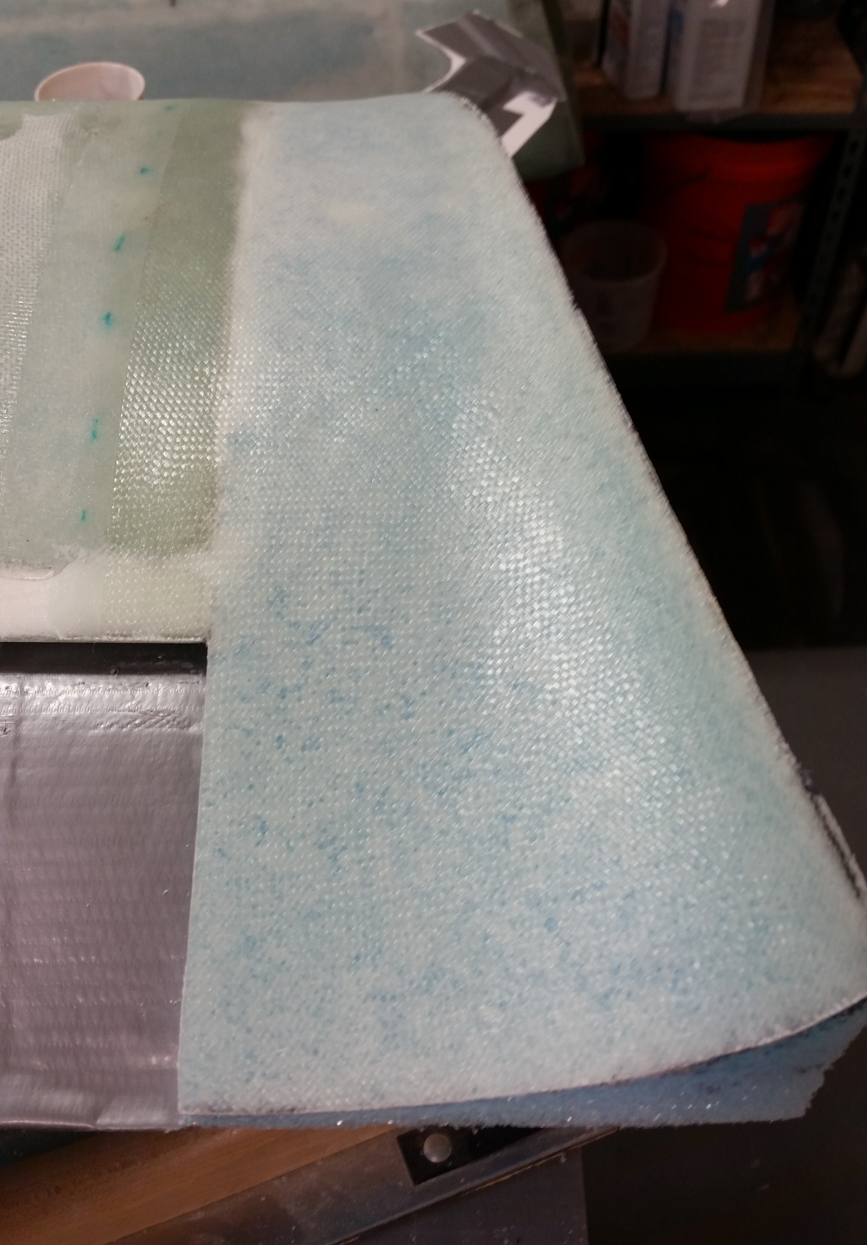
And here are the smaller bits ‘n pieces after I hit them with some 80 grit.

Fine sanded stuff!

After I got the weight notch sorted out, I mixed up some West epoxy and started applying epoxy swipes to the remaining parts of the bottom of the canard that weren’t finished (swoosh tips, swoosh tip inboard rib, weight notches, etc.).

Pure epoxy wipes

Here’s a shot of the right inboard swoosh tip area after a couple of coats of epoxy.  And a shot of the glassed right elevator notch with 1-ply BID.

Right weight notch glassed

Below is a shot about 9 hours after the one above, and the tips are covered with 5 coats of epoxy.  I’lll let it cure overnight and sand it tomorrow.

5 coats of epoxy!

On with the nose gear!

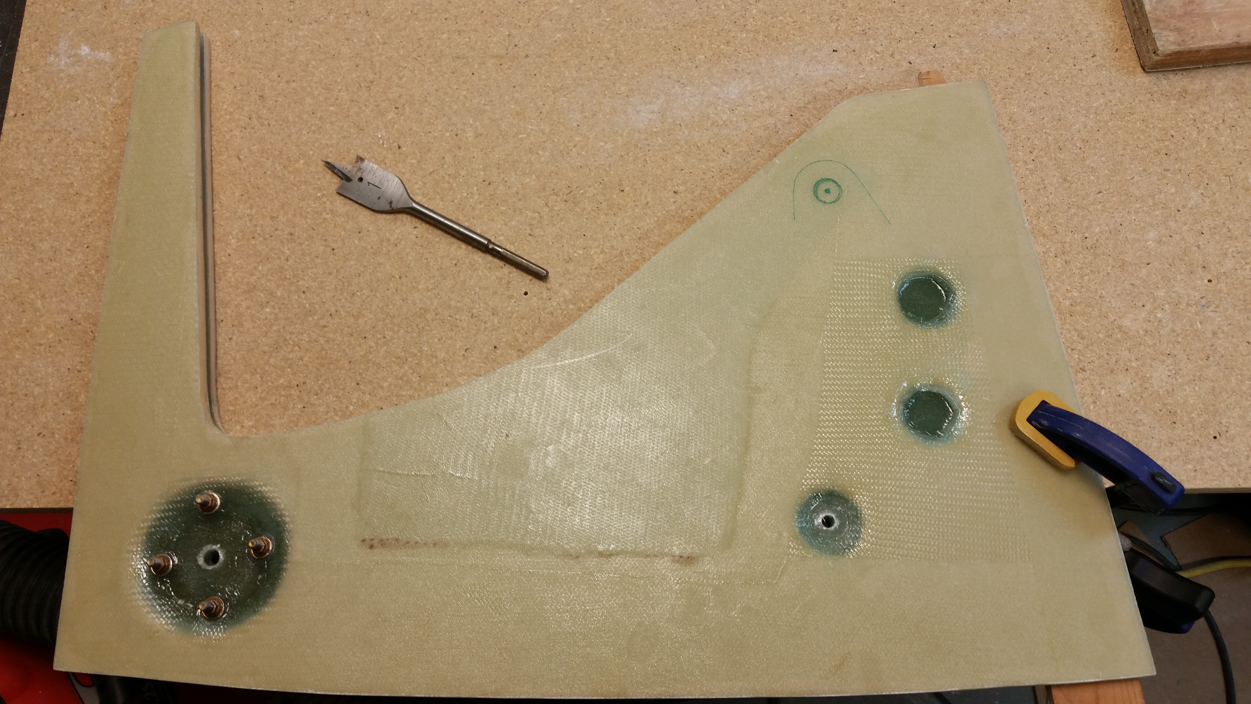
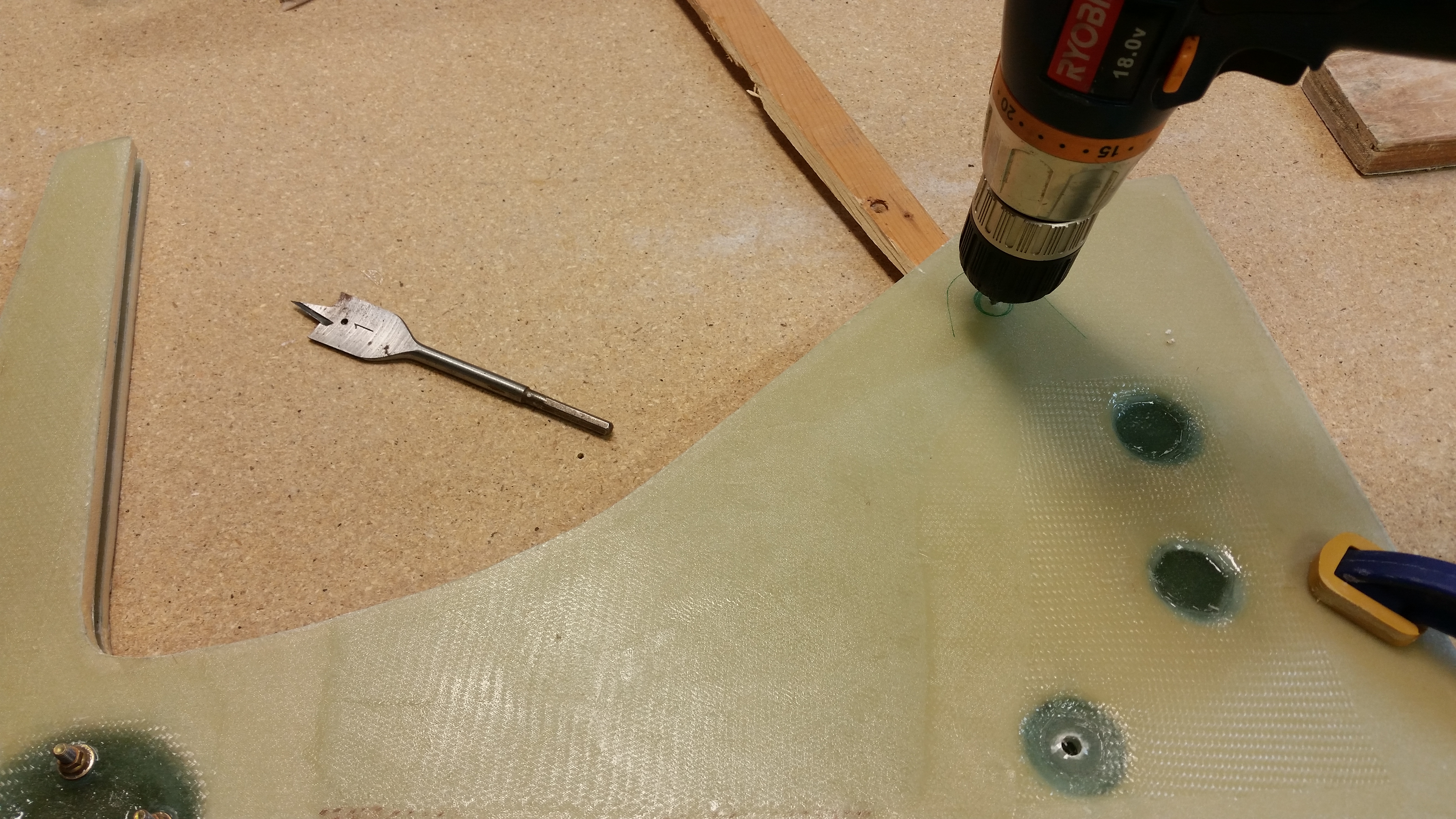
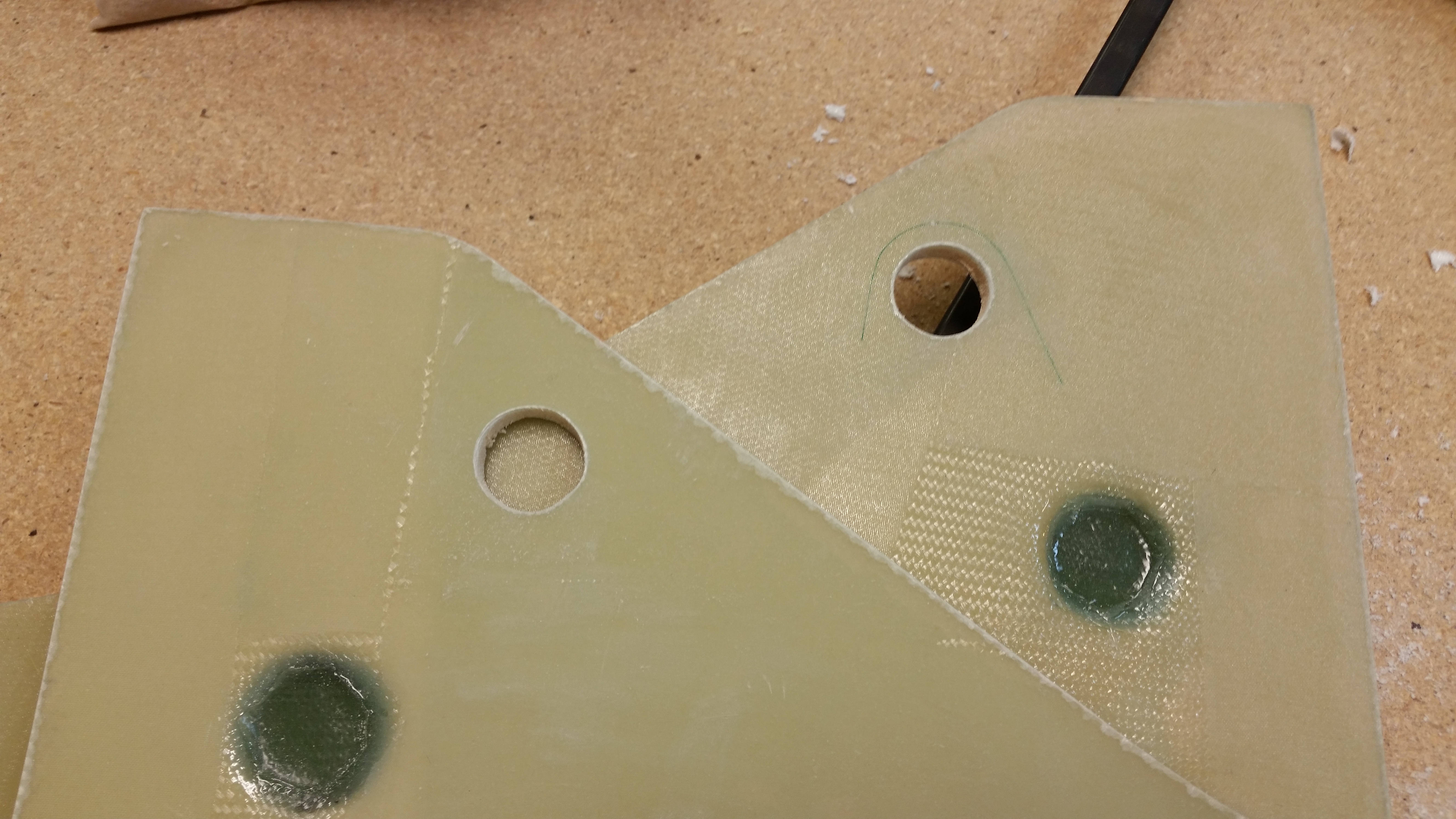
I measured everything out with the sidewall brackets that sit internal to the NG30 plates and hold up the electric gear actuator.

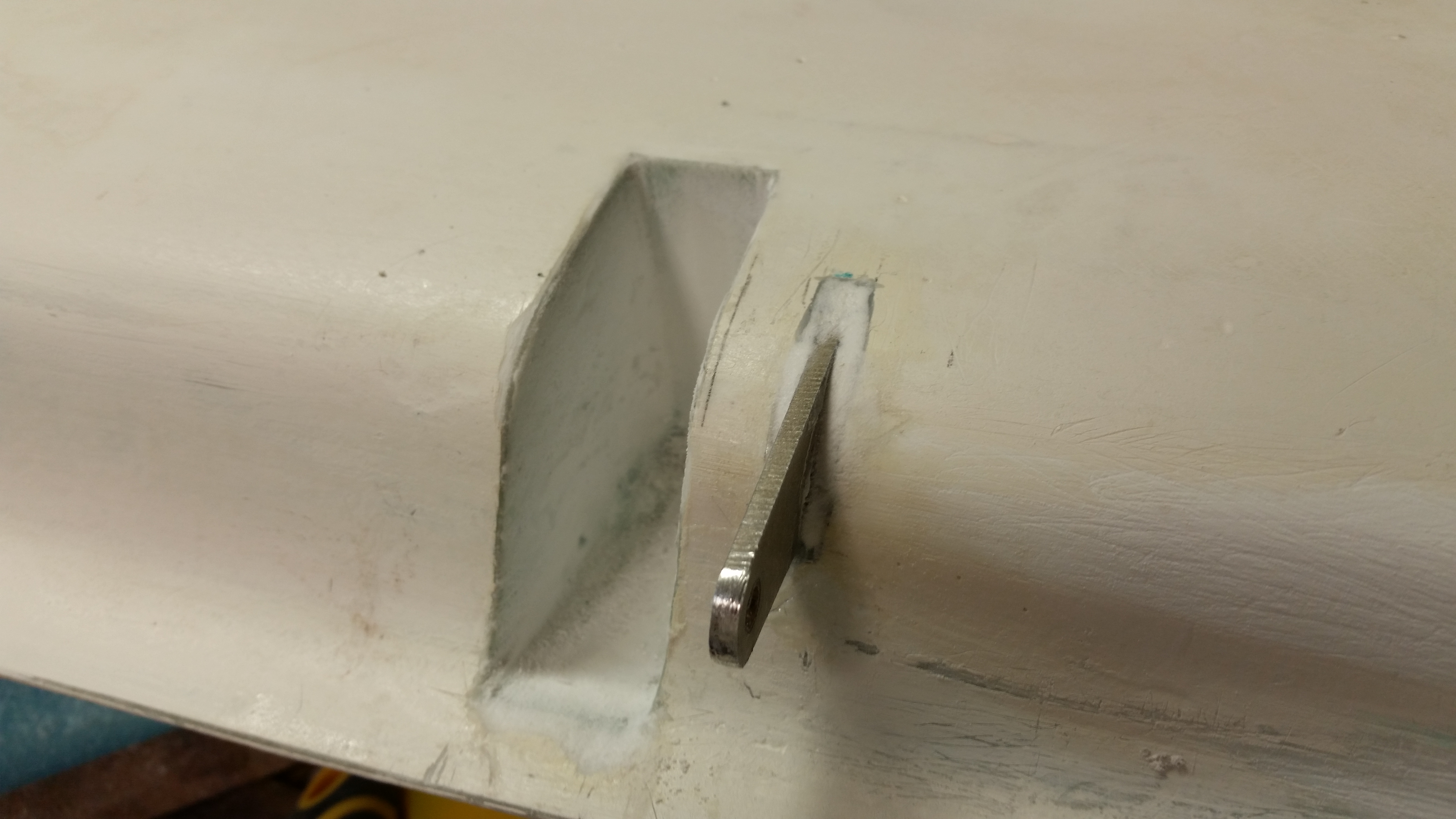
Drilling top NG30 holeDrilling top NG30 hole

Unfortunately my zeal got the best of me.  After checking something in the gear actuator install instructions I ran across a statement where the holes in the brackets (not shown) need to be 3/8″ away from the side of the bracket at the center of each hole.  Mine were set at a 1/4″ away from edge to hole’s center.  This changed the angle required to get the holes drilled correctly for the brackets.  Not a huge a deal, I’ll just have to widen that top hole a bit aft.

Drilling top NG30 holeTop NG30 holes drilled

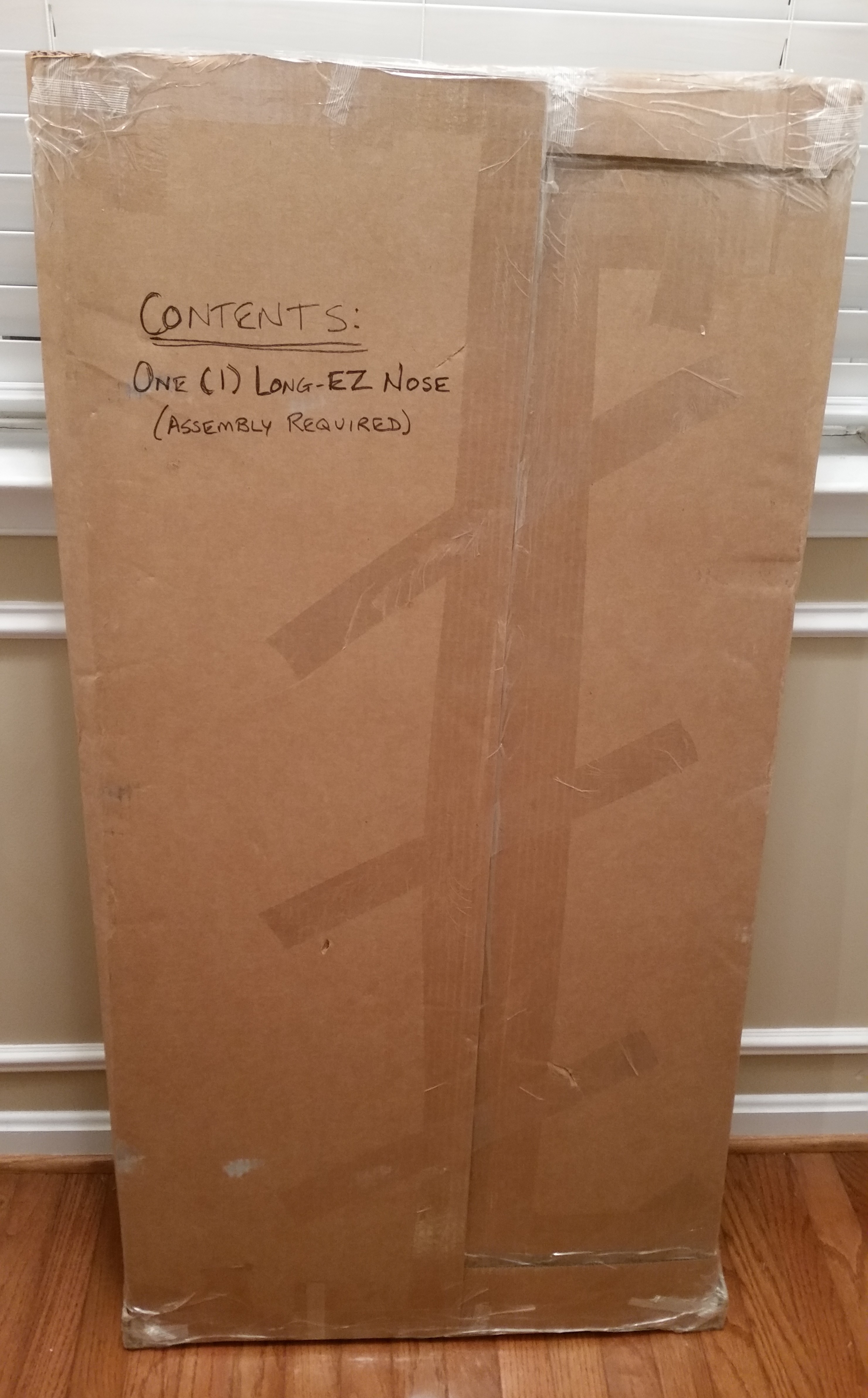
Oh, and speaking of NG30’s and stuff, look what just came in the mail:  my nose!  Says on the box that some assembly is required!  Haha!

Yeah! The nose came! Ha!

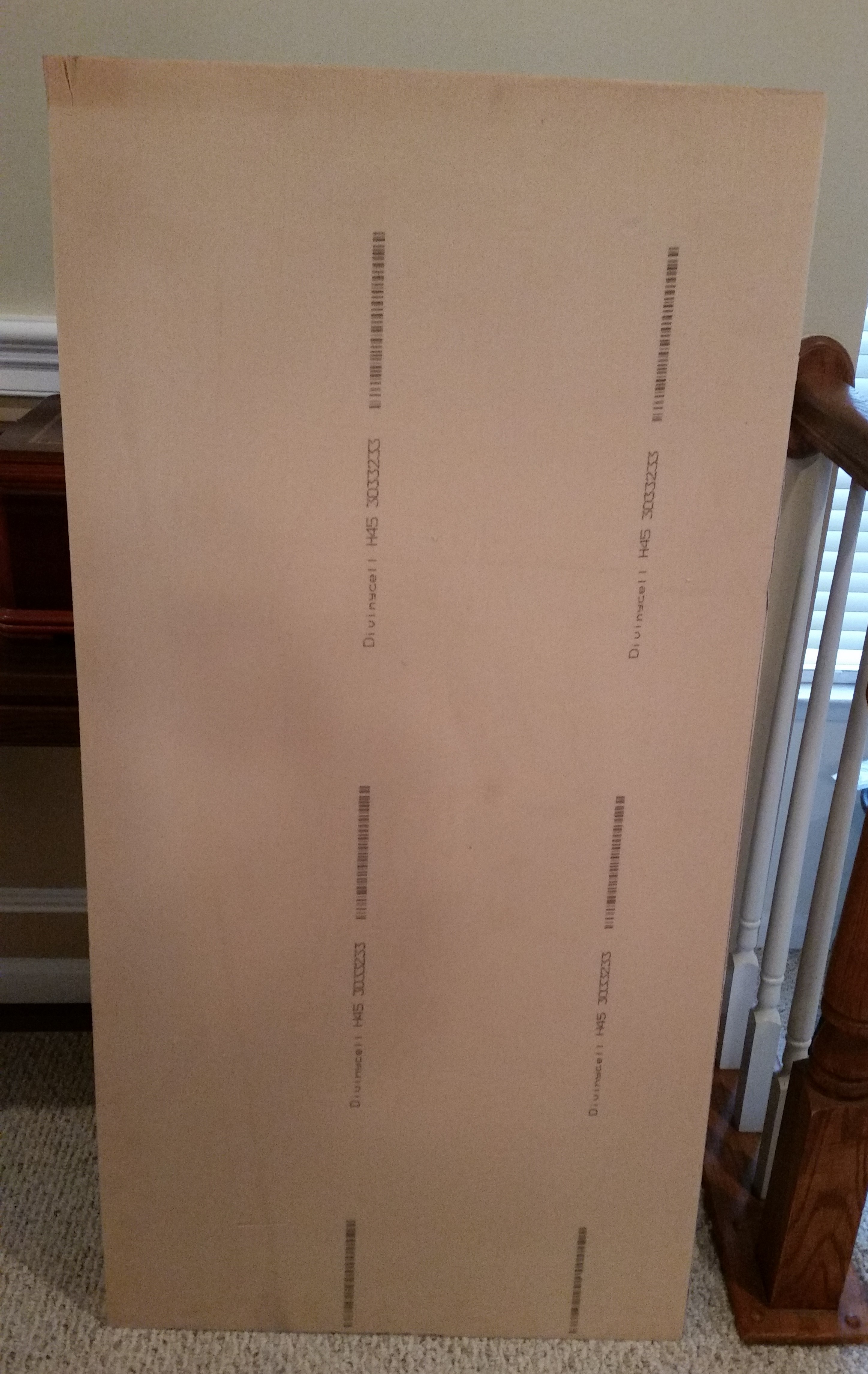
Interestingly, I was just having a conversation the other day with a good builder buddy of mine talking about how some builders have yellow foam in their build that isn’t polyurethane, but actually Divinycell (H45).  Well, guess what?  My “blue” Divinycell foam showed up yellow.  I mean, I asked ACS if they could send me the lightest Divinycell possible . . . but I was talking WEIGHT, not COLOR!  ha!

Yellow Divinycell? Who knew?!

Chapter 10 & 25 – A New Itch!

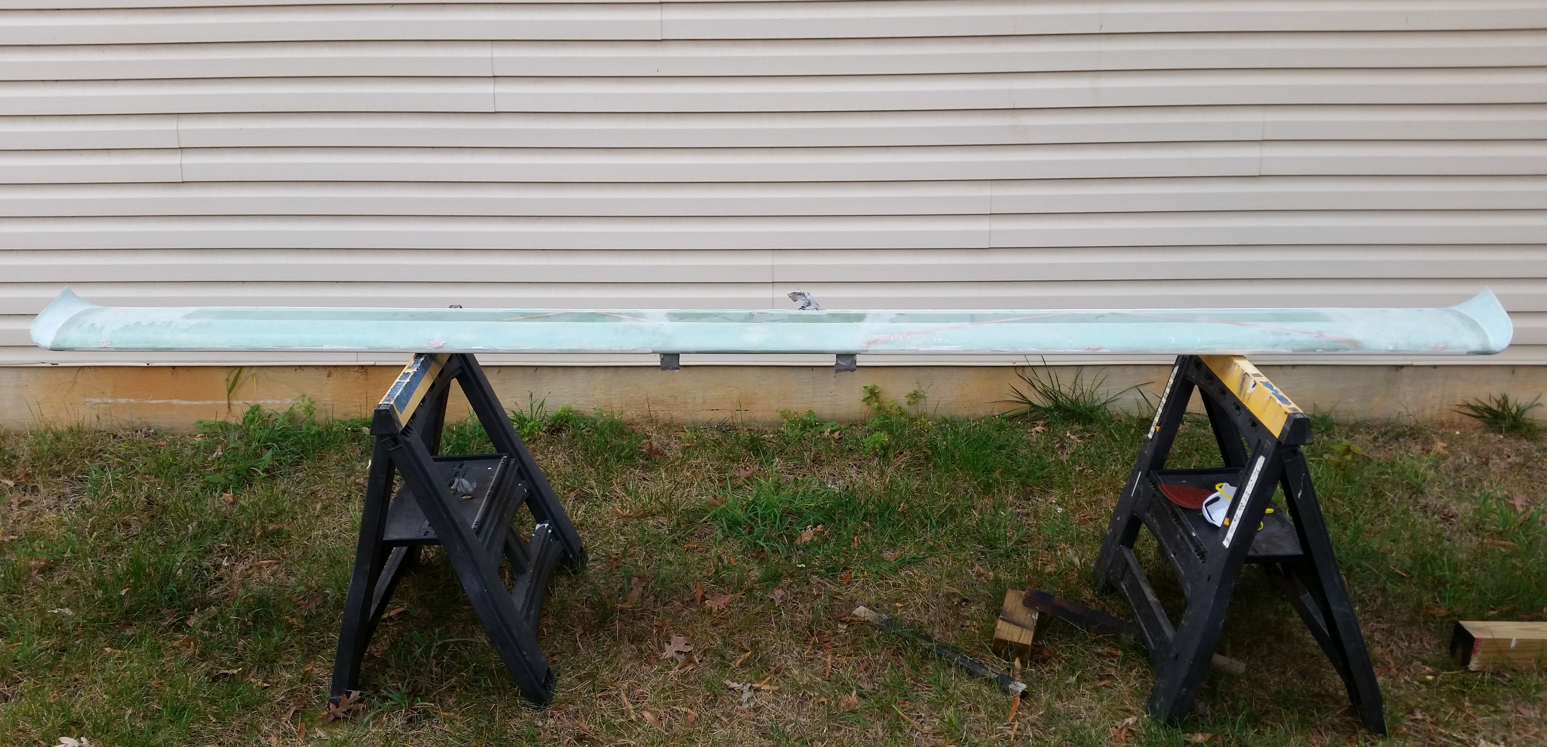
Seriously, I did a ton of sanding on the canard today to prep it for finish, and yeah, I got the itch!

I set up my gear & took the canard outside to sand that sucker!

Now, I will say that before I actually started sanding the canard, I spent about 2 hours  researching & documenting the nose install & nose wheel mounting .

Sanding Canard for finishSanding Canard for finish

Below is a pic of how much of a mess I made by sanding the top of the canard. The pic below shows it all clean & ready to got back into the shop.

Sanding Canard for finishCanard sanded for finish

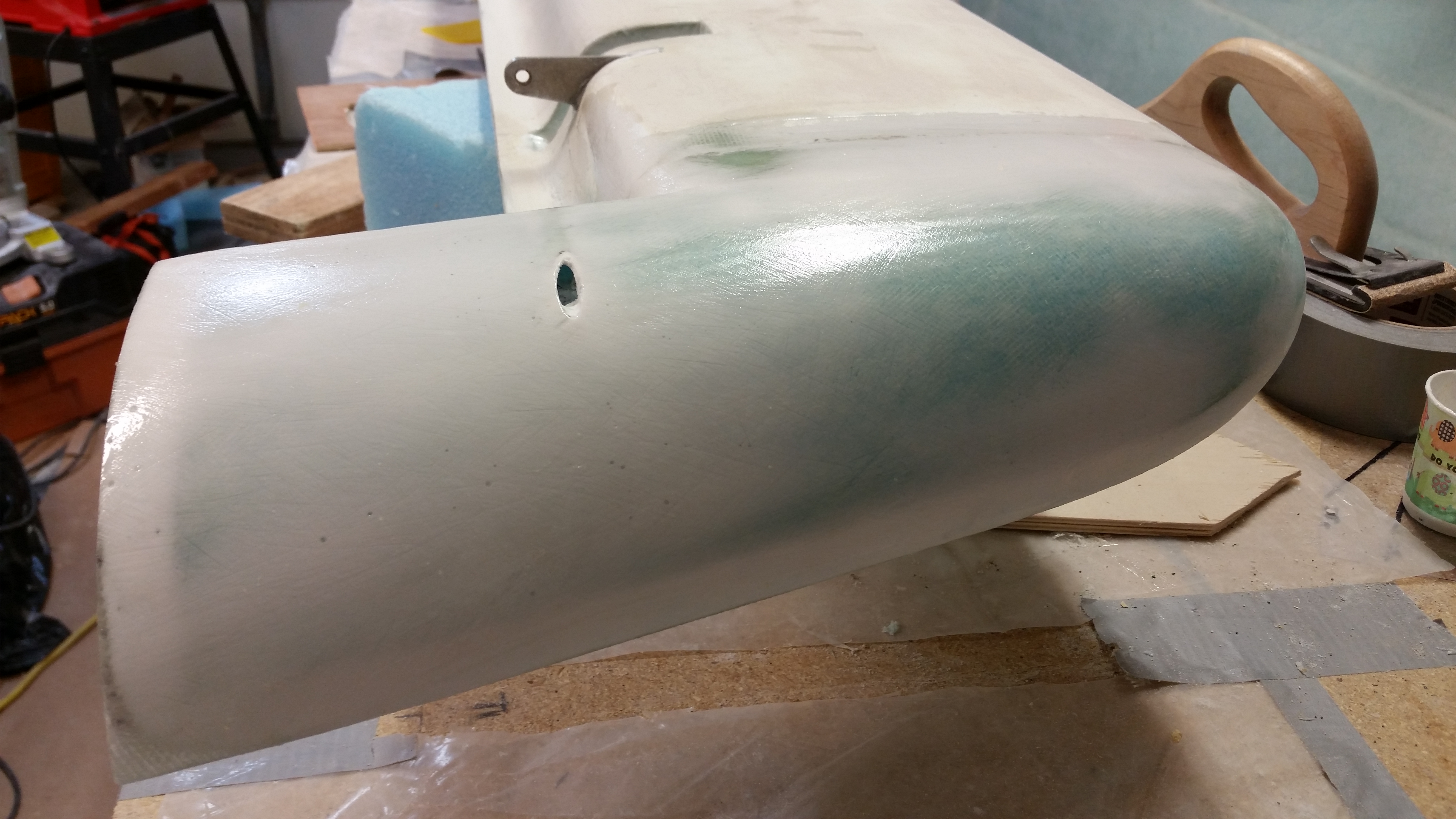
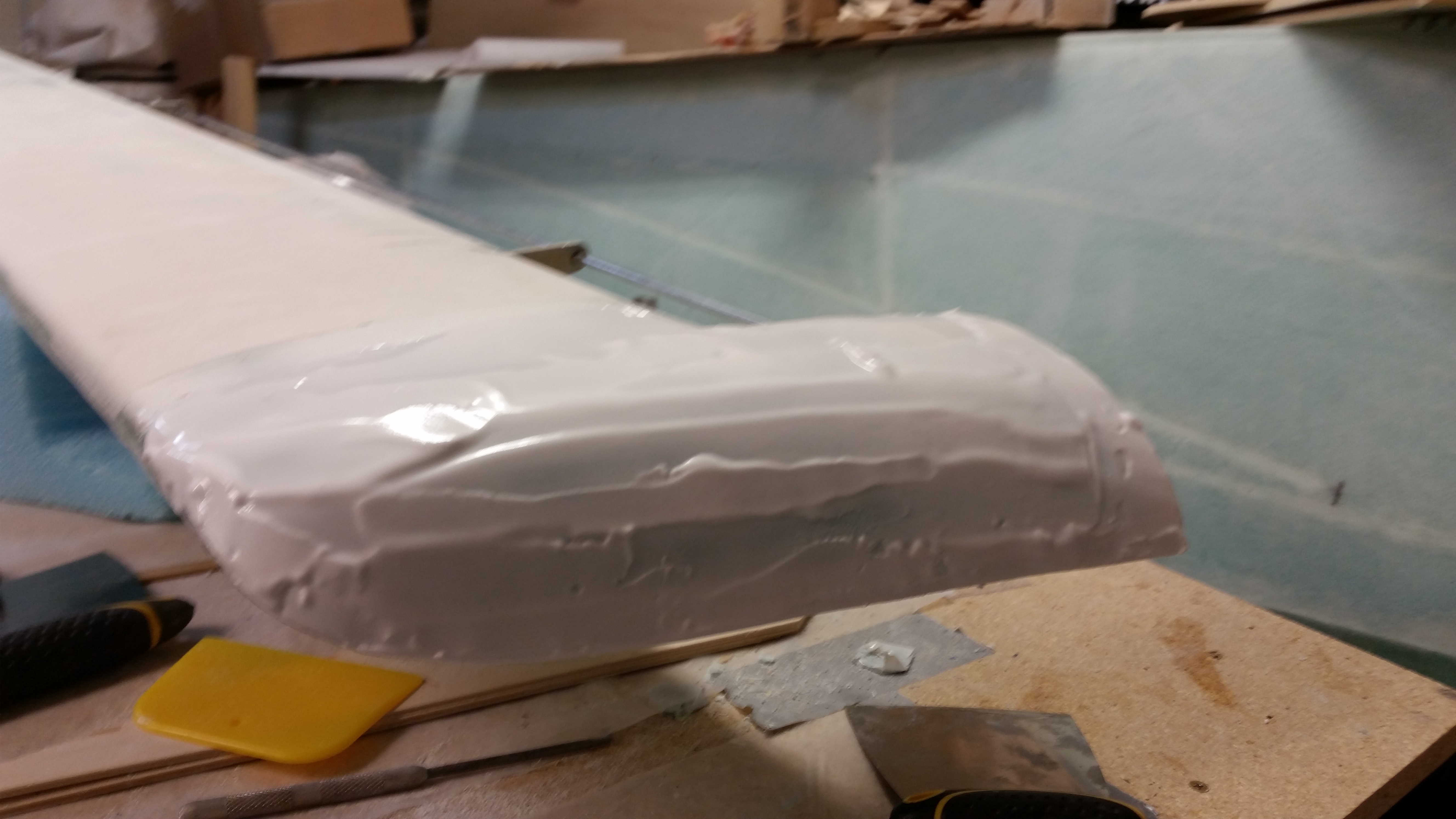
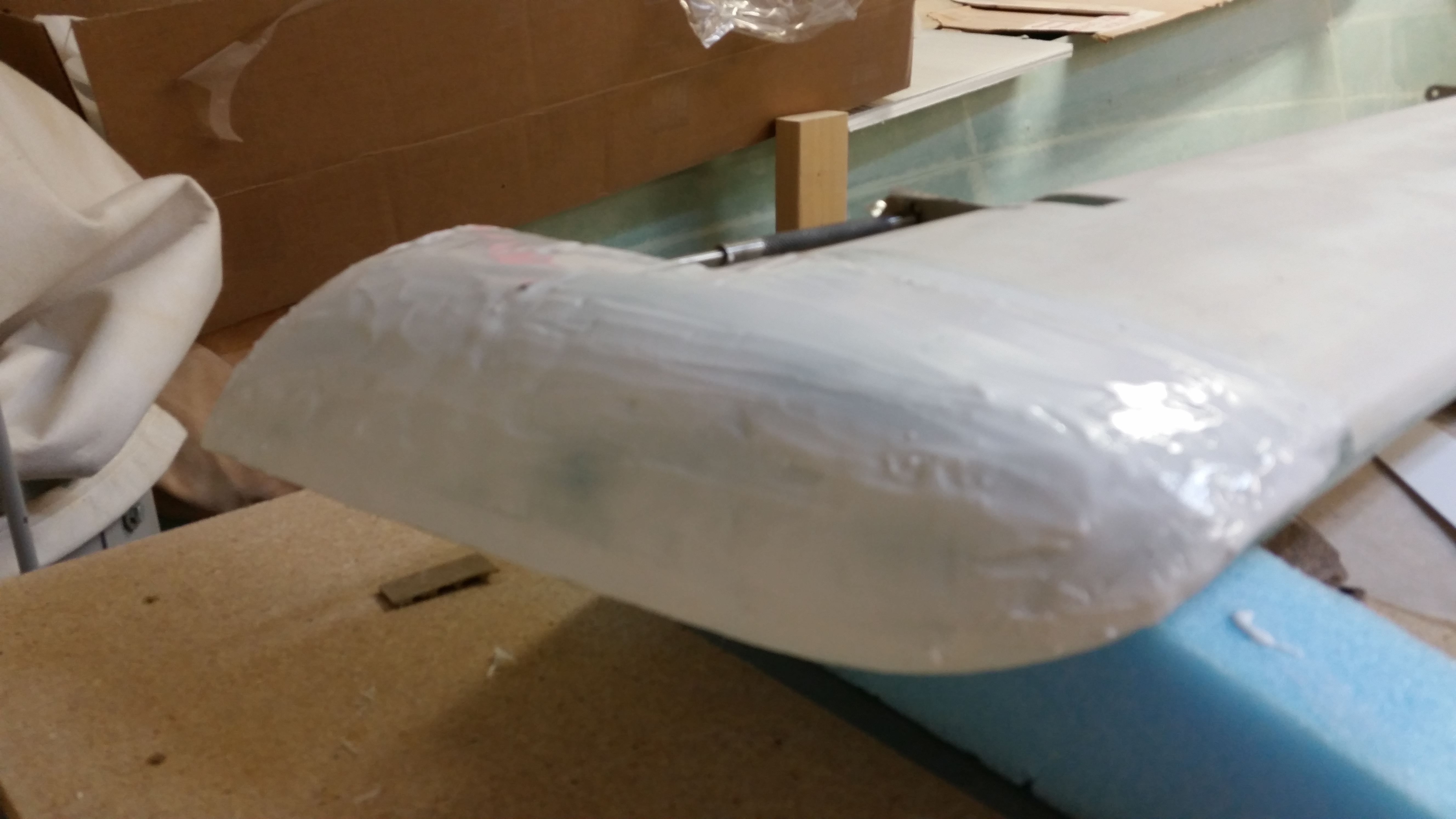
Once back in the shop I whipped up a fresh batch of micro finish using West epoxy to apply to the bottom surface of the canard.  I’m starting back on the bottom side to blend in the newly added canard “swoosh” tips.

Micro finish applied to swoosh tipMicro finish applied to swoosh tip

Here’s the shots of the inside rib of each swoosh tip:

Micro finish applied to swoosh tipMicro finish applied to swoosh tip

Since I had time & micro finish on my hands after swabbing down the swoosh tips, I heated up the cup and applied the micro finish to the ice shields.

Micro finish applied to Ice Shields

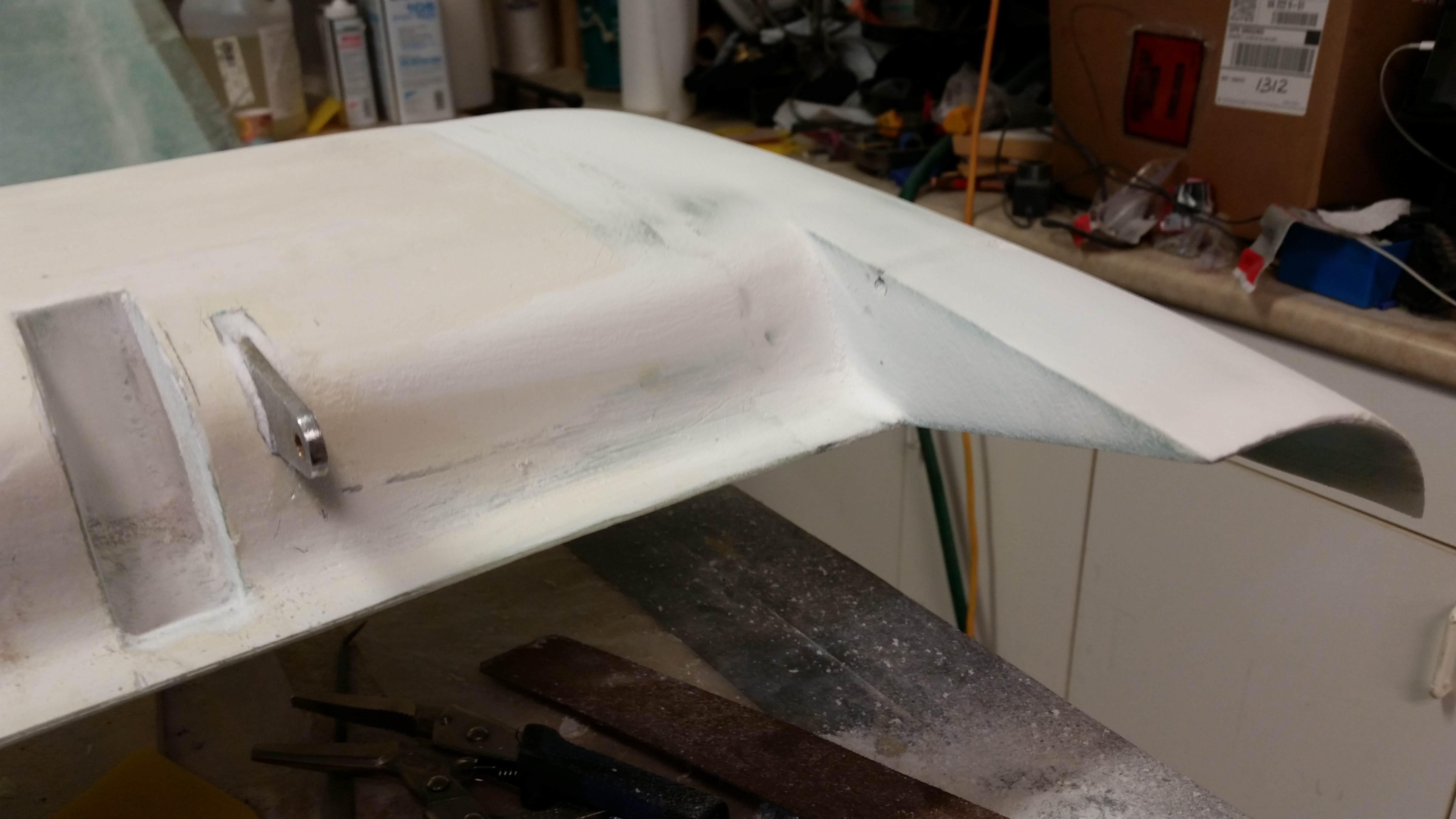
A few hours later after the micro “greened” I cheese grated it.  All I have to say is Wow!  Since I waited about another 45 minutes from normal time (2-3 hours vs my 3.5-4 hours… obviously YMMV) to cheese grate this thing, it worked like a champ.  As you can see I got all the major bumps & grooves sanded out on these added canard tips.

Swoosh tip cheese grated

Swoosh tip cheese grated

And again, here’s the inside “swoosh” tip rib that also got micro’d & then cheese grated (both sides):

Inboard swoosh tip cheese gratedInboard swoosh tip cheese grated

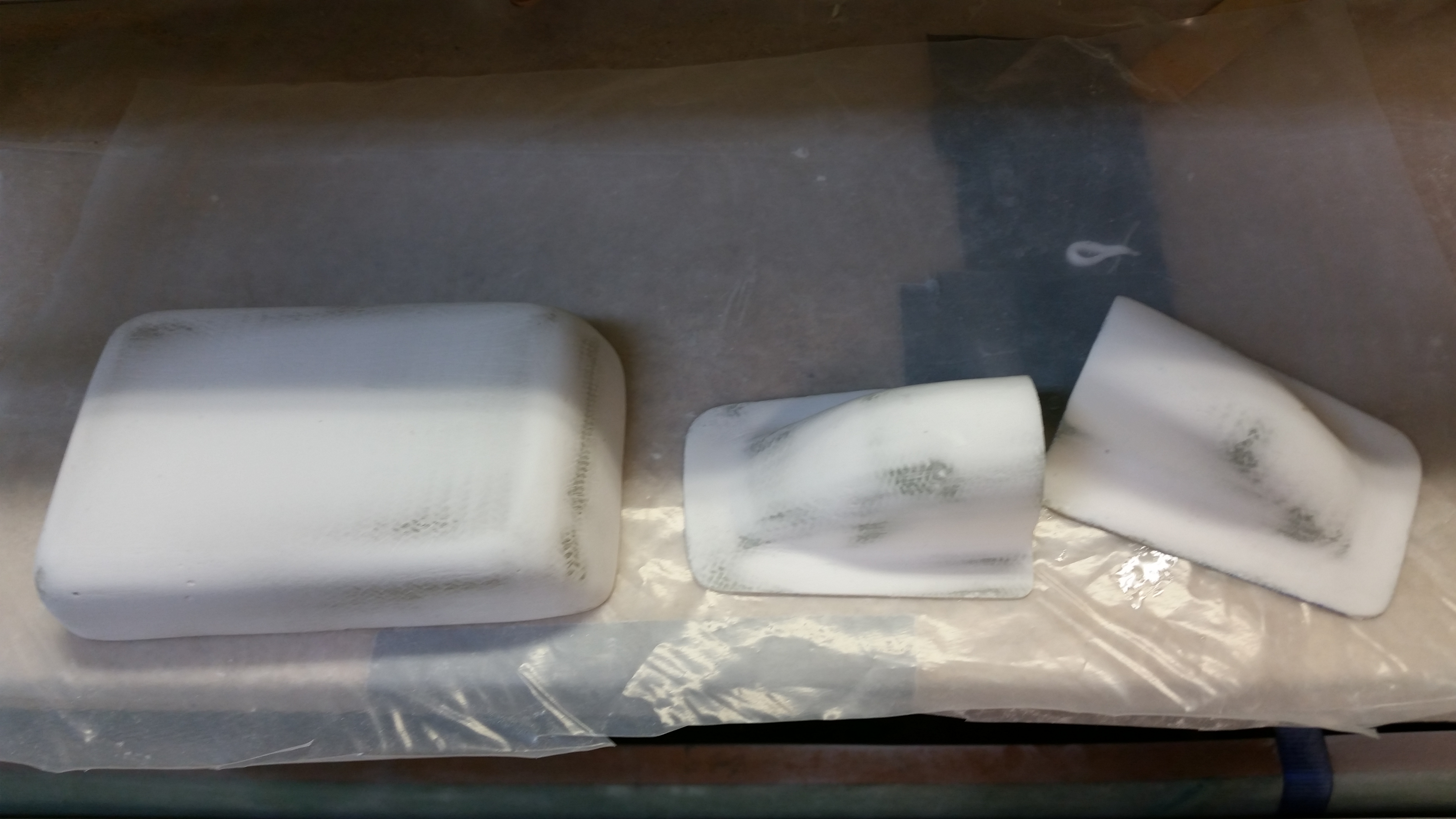
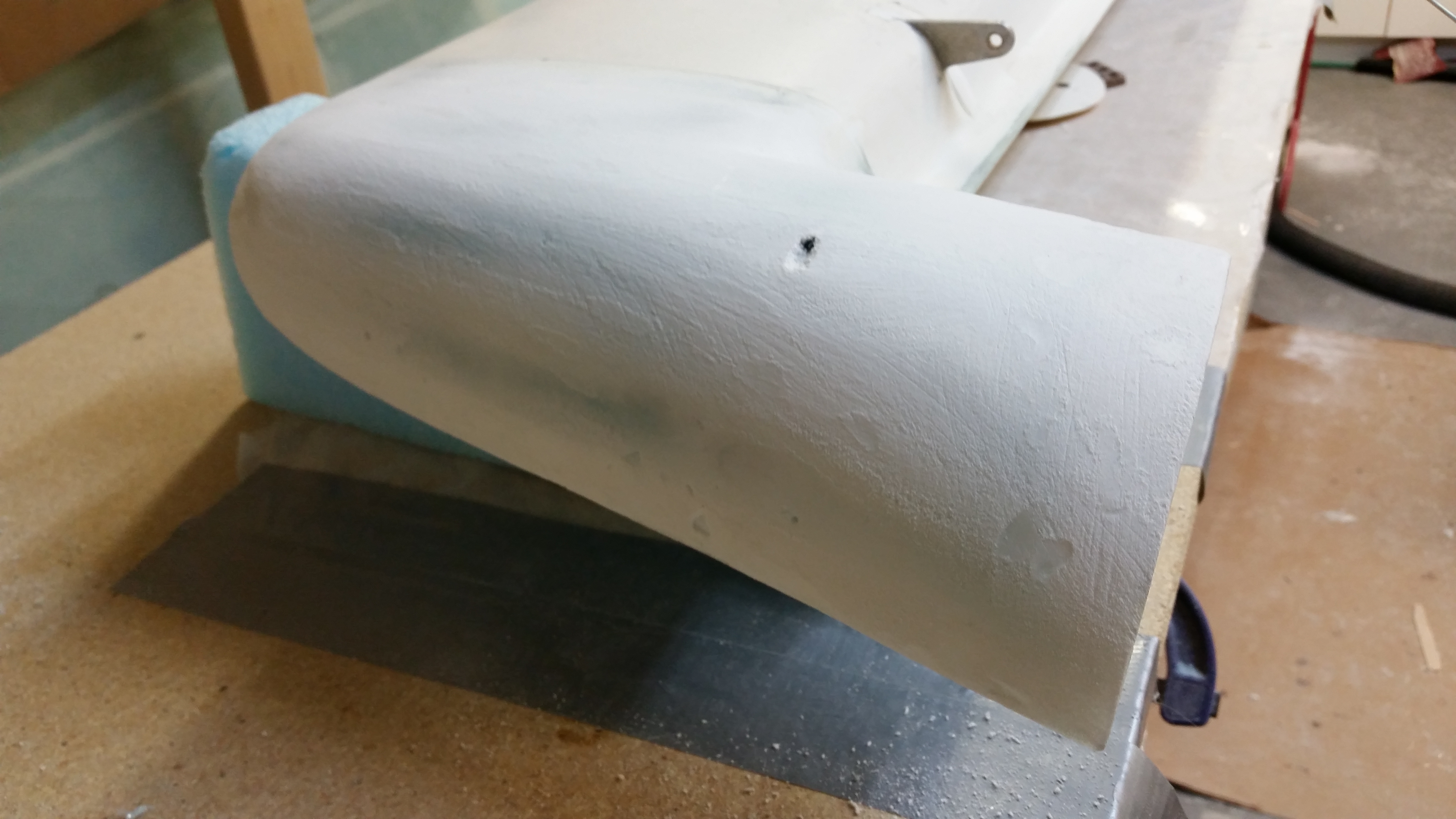
Finally, since I was working with a ton of micro finish, I also finished the various small parts I have in the works such as the ice shields and the GPS antenna cover from atop the modified headrest.

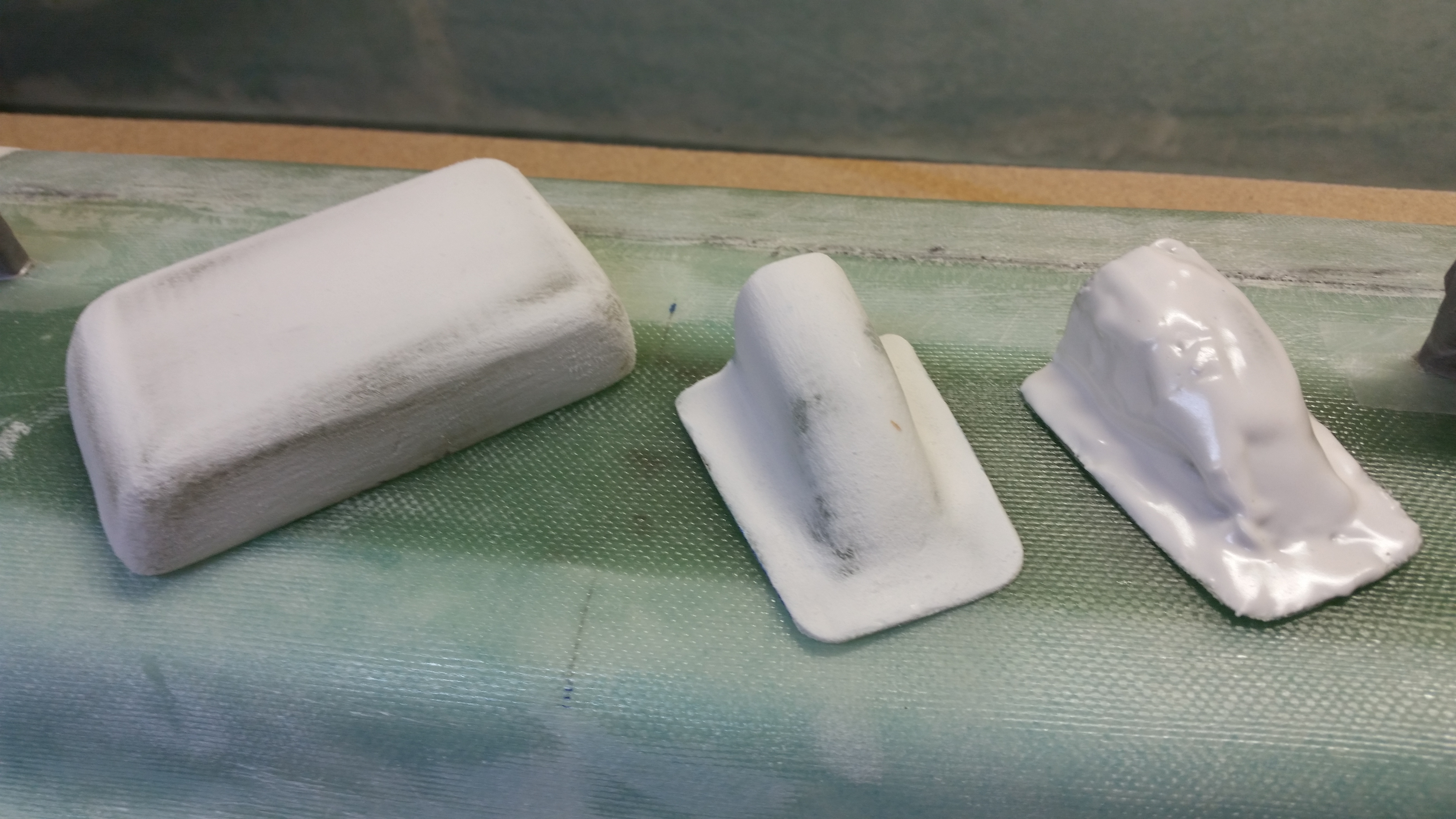
Here is an example of cheese grating vs not cheese grating:

Cheese grating vs no cheese grating

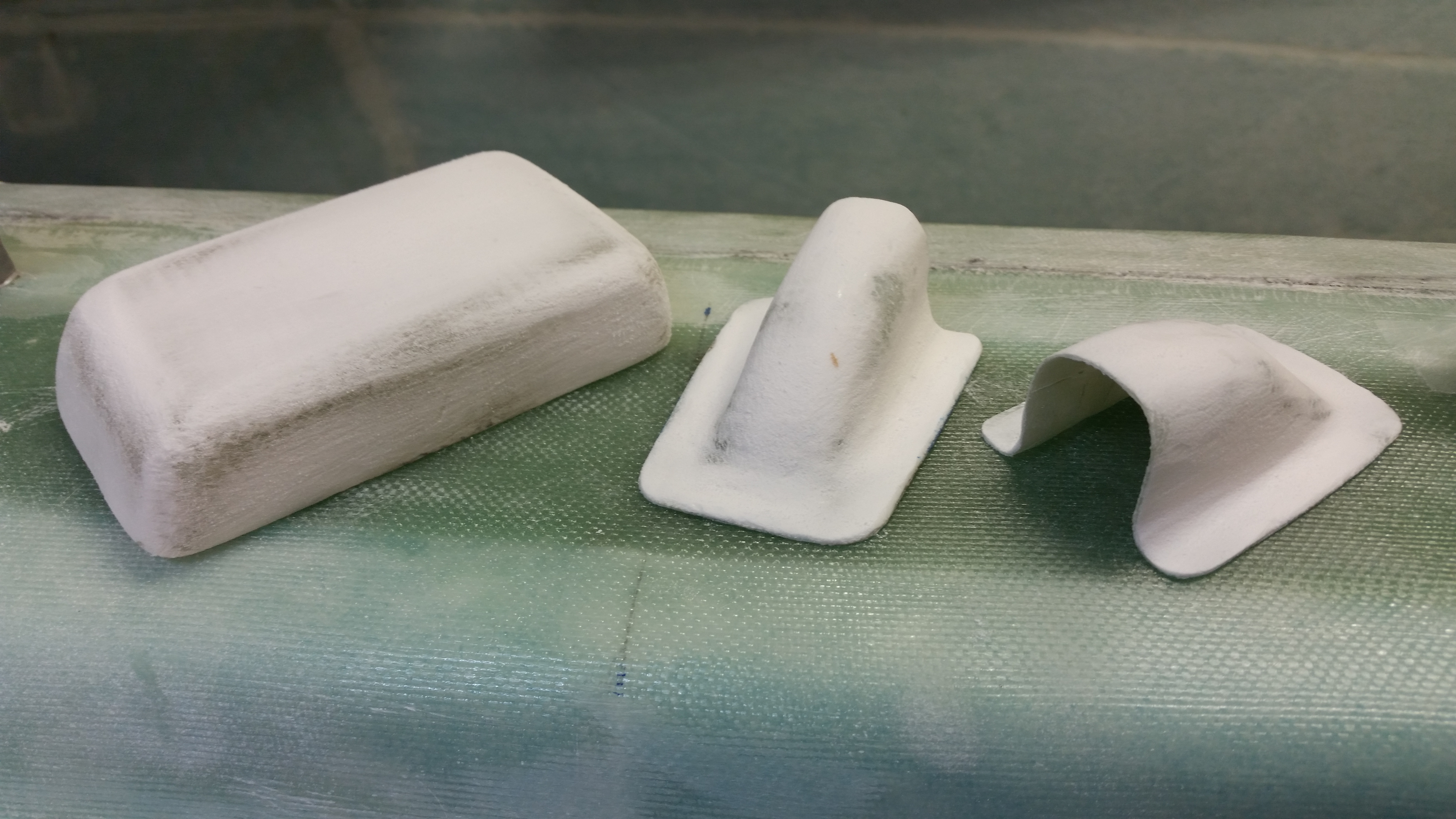
And then when all are cheese grated:

Cheese grating wins!!


Chapter 11 – One redo please?!

I will apologize right up front for not getting the requisite pictures that I promised of the elevators in their progressive state.  I will attempt to tell the story better visually as it progresses.  Right now I have the offending Right elevator with one Micro Skim coat applied to the underside of it and I will be sanding it down & applying either another Micro Skim coat or a pure epoxy wipe tomorrow.

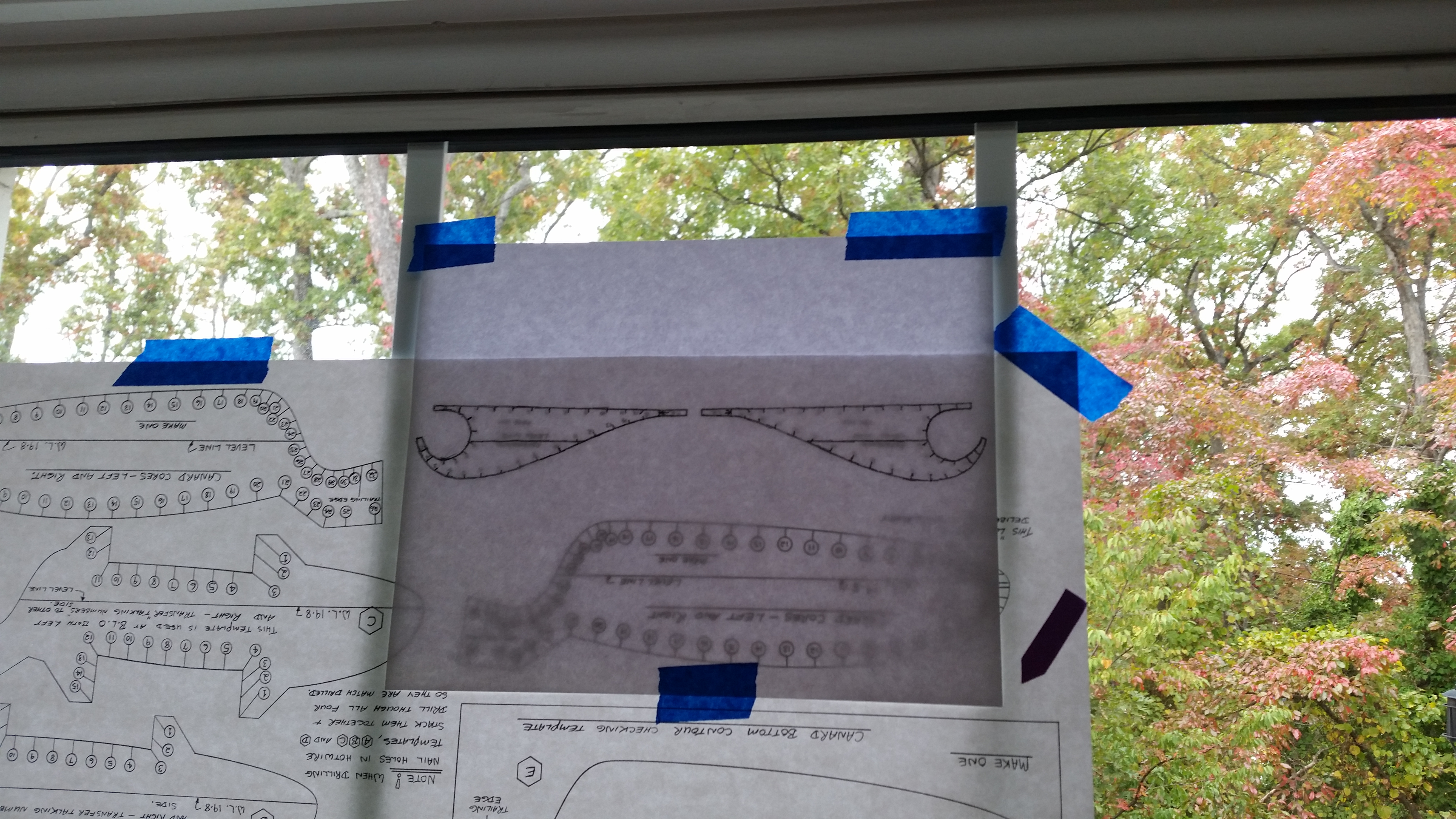
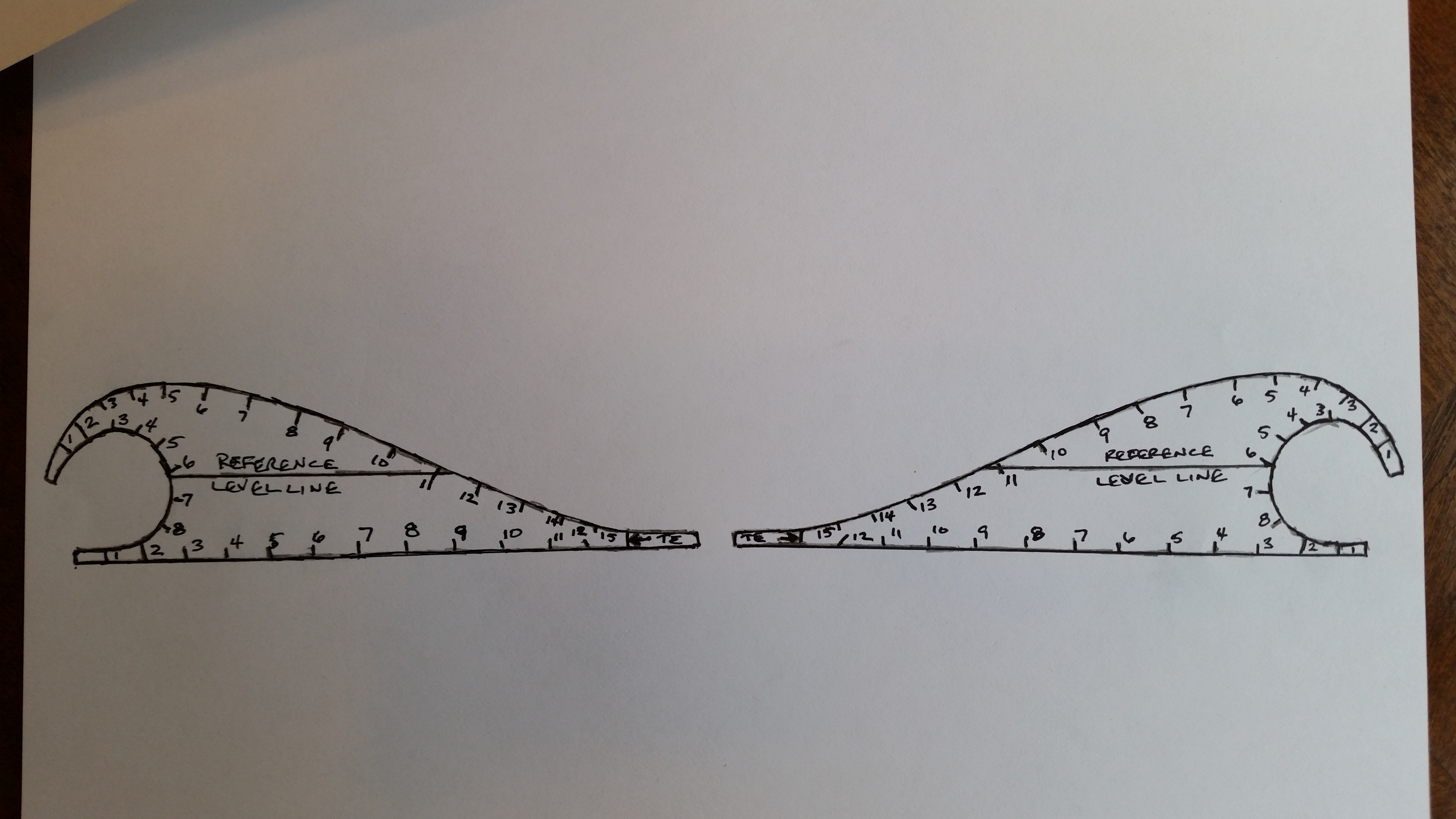
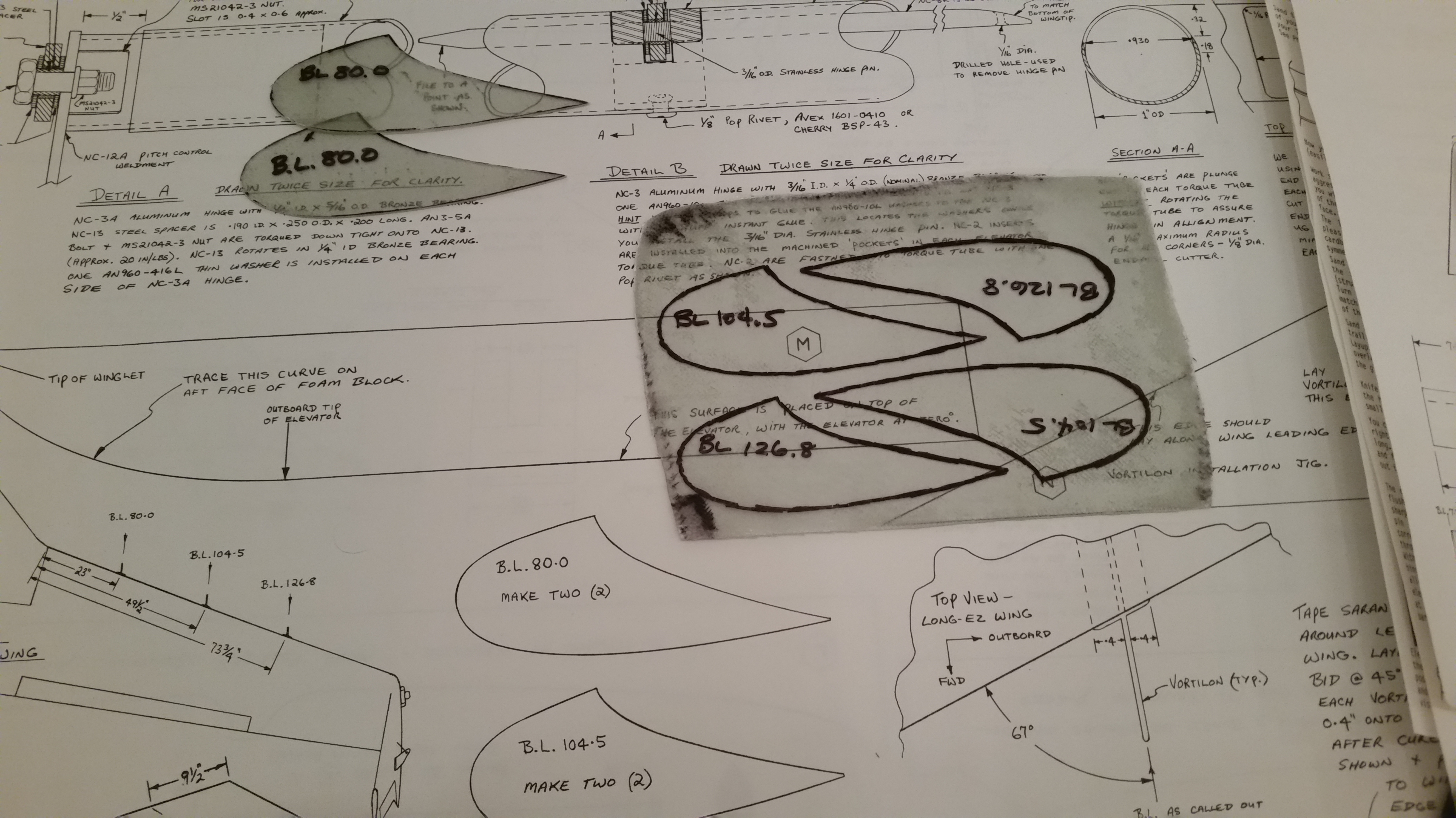
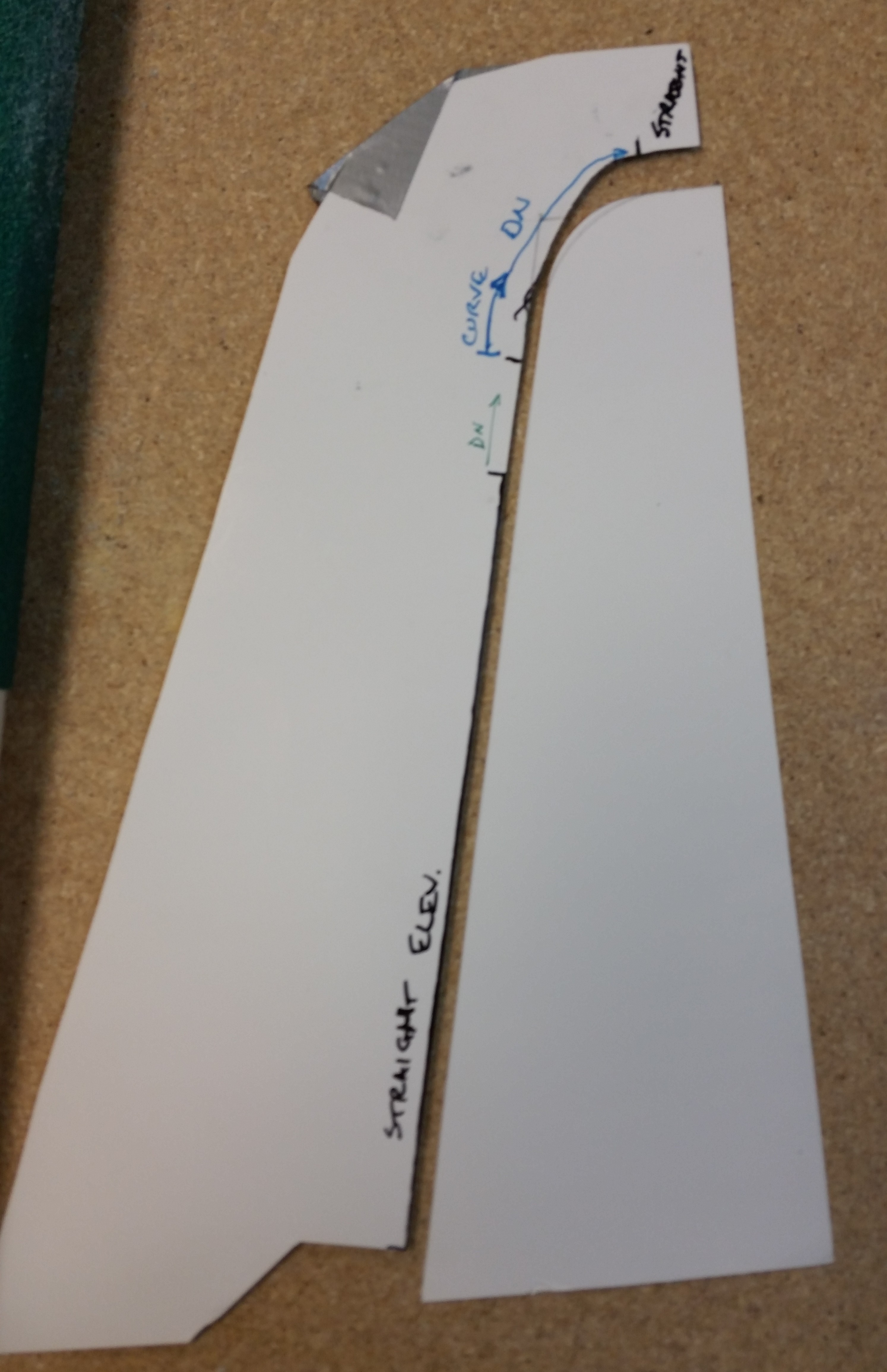
In the mean time, to ensure I have everything I need to hot-wire another elevator, I traced the Roncz elevator templates off the plans onto a piece of paper.

Tracing Roncz elevator template

Which resulted in this:

Tracing Roncz elevator template

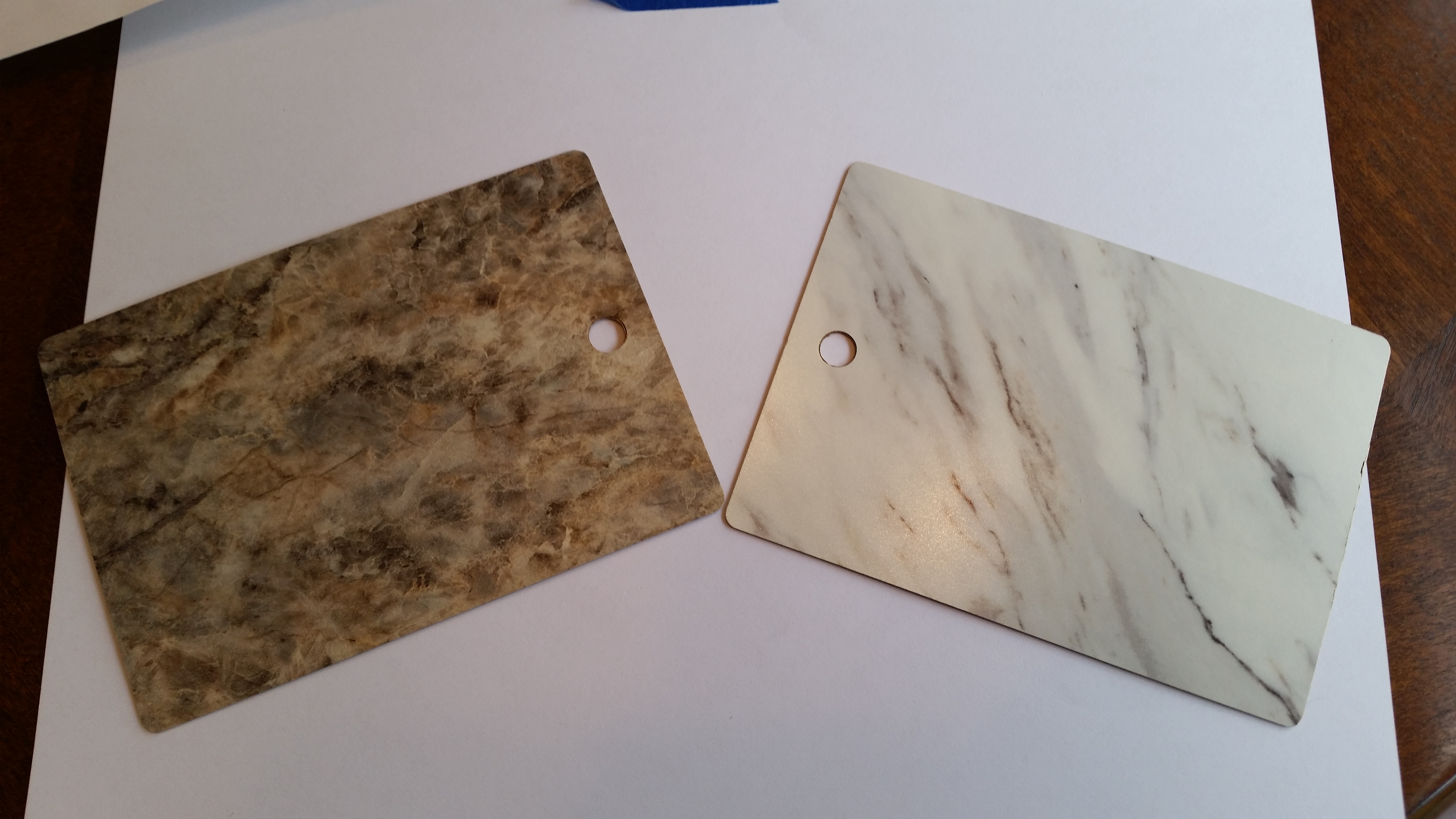
I had been to Home Depot earlier getting various items for the build, including a 2×4 to lengthen my hot-wire cutter.  While there, I found these Formica samples in the cabinet aisle, so I snagged them.  Not bad for free!

Formica samples

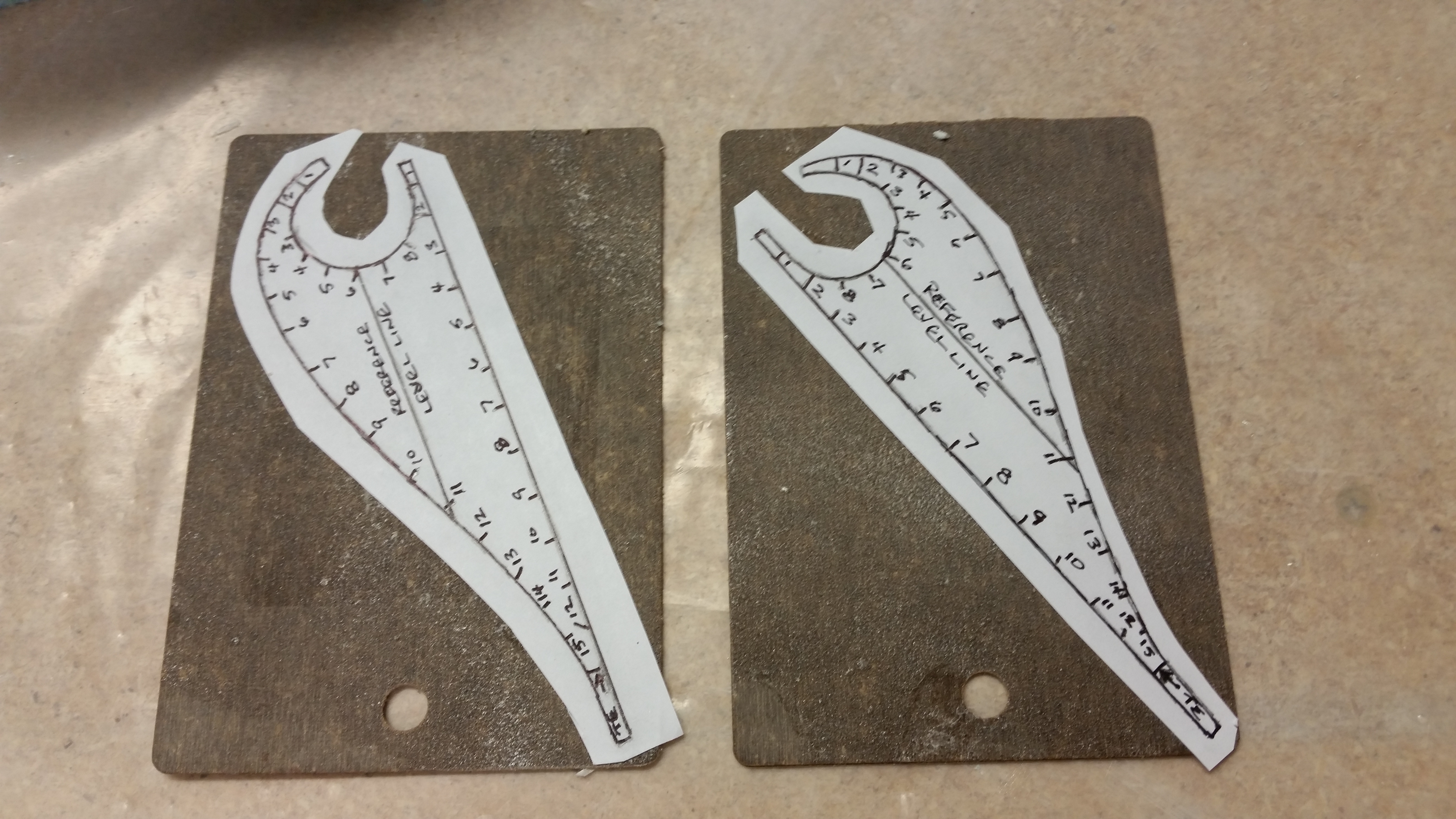
I then spray glued the elevator templates, after rough cutting them, to the Formica samples.

Templates glued to formica chips

OK, I’m going to get on a huge soap box here!  I have learned a ton from many who have gone before and completed these airplanes, but in general, there are many builders who are like birds in a nest squawking the same old tired songs.  I read in the plans (the culprit) and then in a million and one places that Formica is the best for hot-wiring templates. Now, I admit I could have done something wrong in my application of employing Formica in creating my elevator templates, but the bottom line IMO is that Formica sucks!!!!  It broke, shredded, snapped, crumbled, etc. as soon as my jig saw touched it.  So, after getting ready to go back to the store to buy some stuff that ACTUALLY works!! I found an old license plate that would work.  So, instead of using the worthless piece of crap Formica,I moved on to metal:

Formica blows! Moving to metal!

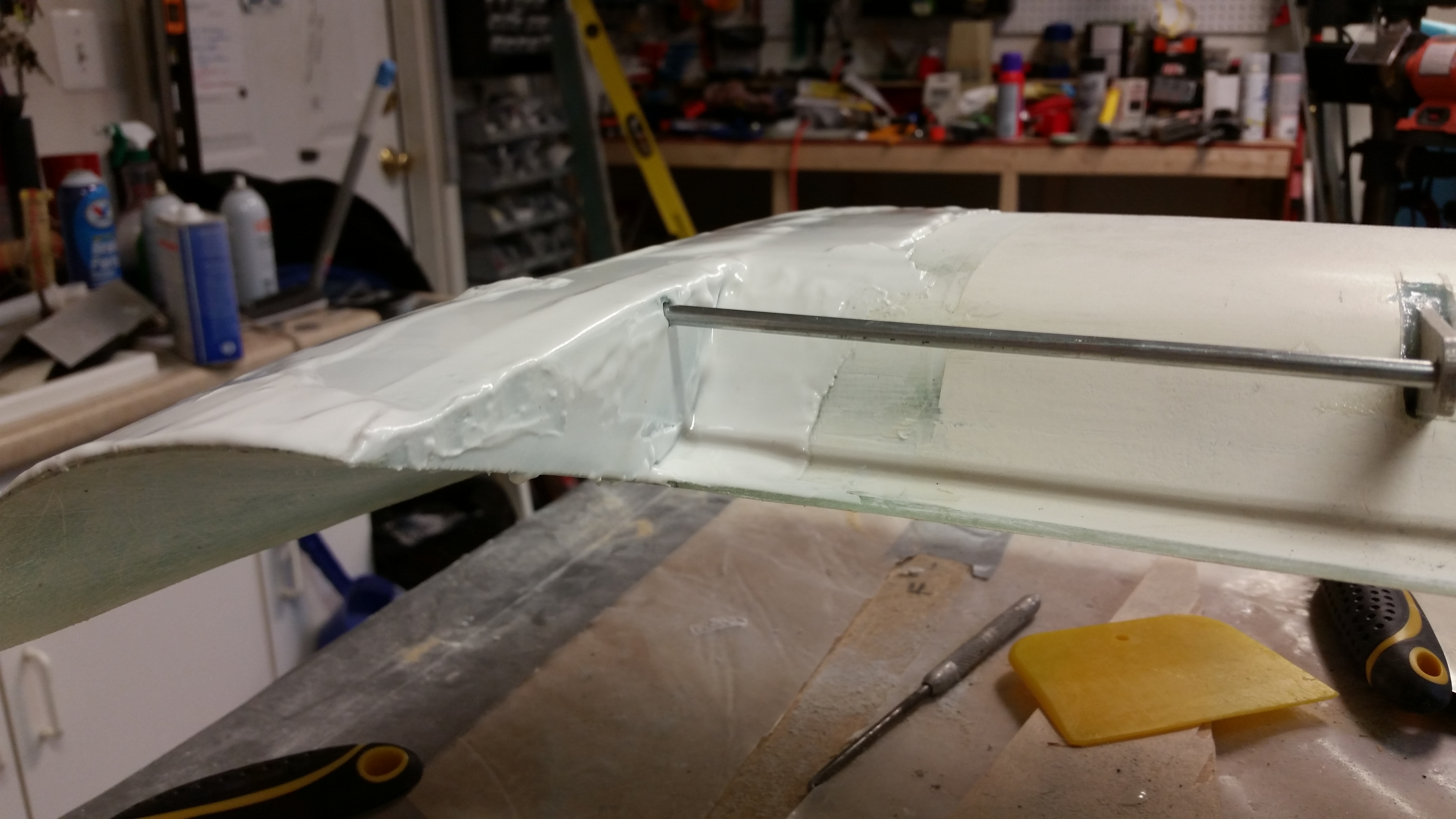
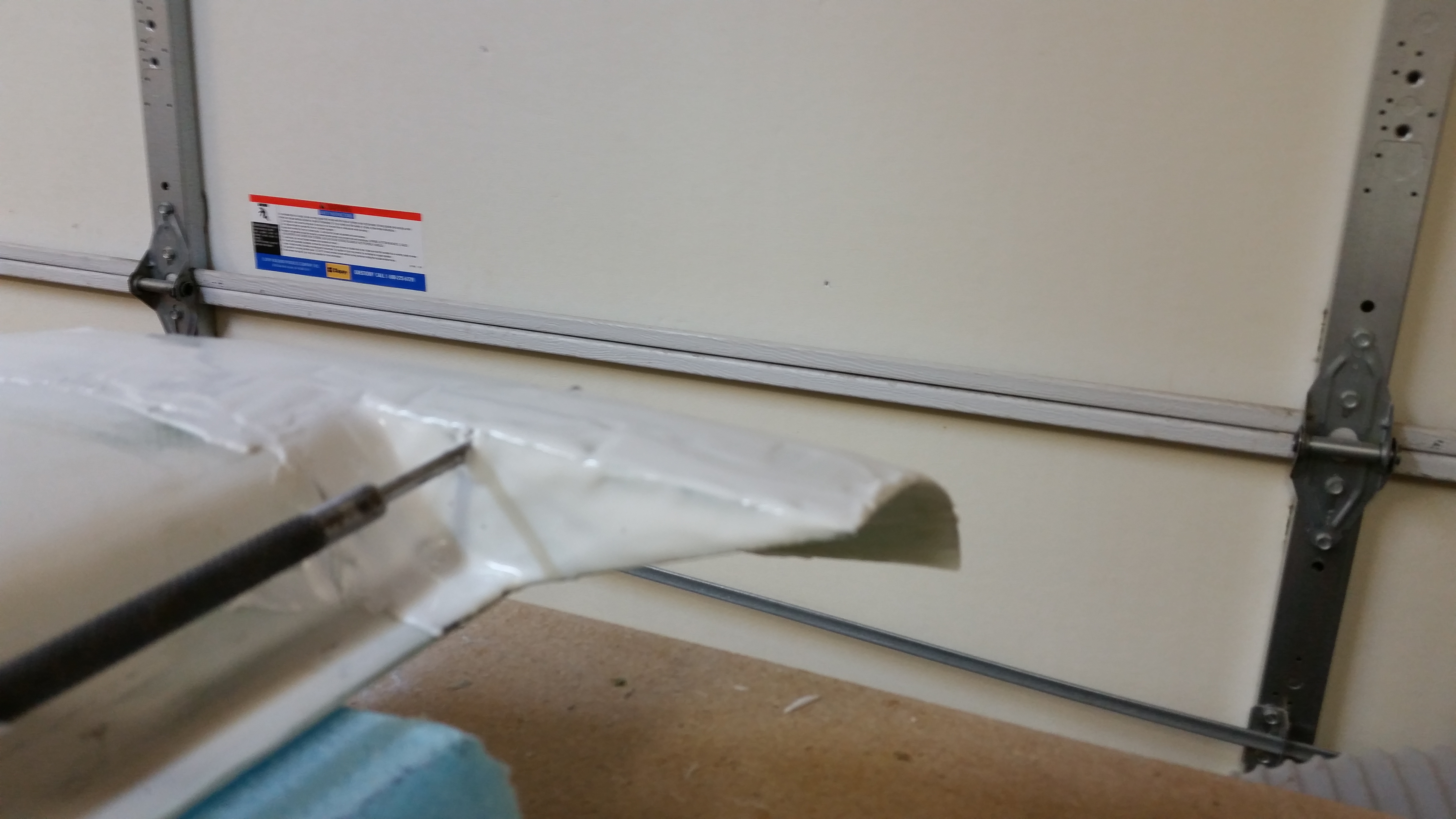
Ok, again, no pics here.  But in the end it didn’t matter what I used.  After messing around & testing my hot-wire saw, it’s just plain old & tired.  I test drove it using the metal elevator templates I made, but it just didn’t have enough oomph to cleanly cut the foam.  I thought I would at least try.  So, instead of spending more money on getting new parts for the hot-wire saw, and more time, I’m punting and will simply order another elevator core (technically a pair) from Steve at Eureka CNC.

Finally, just thought I’d throw in a pic showing that I finished & trimmed the canard ice shields:

Ice shields - trimmed

Chapter 11 – Sins of the past . . .

. . . always seem to come back to haunt us.

I don’t have pictures of the real story here, because it involves me using both hands to check the balance of the elevators.  Going back to when I built my elevators in 2013, I had Bondo’d them down to the workbench as it says to do in the plans.  Because the weather was still fairly cool in Germany and the elevators are small & fairly long, I decided to give them a good post cure on the bench to lock in their straight & true lines.  I didn’t want them sitting in storage, as narrow as they are, warping into some weird position.  Well, I guess I should have taken my chances on the latter.

You see, when I post-cured the elevators, apparently the Bondo holding them straight & true on the table was also cooking the foam on the other side of the glass skin immediately opposite of it.  Thus, every single spot that I had a blob of Bondo became a localized skin delam.  To fix the issue, I shot each delam with epoxy after having weighed the elevator first.  Then I compared the weights, before and after, and also to the mandatory weight specs for the elevators (3.5 lbs left & 3.25 lbs right for stock elevators).  The resulting weight for each elevator was right around 1.9 lbs, with less than an ounce gained from the epoxy injections per elevator.

The issue is that both my elevators both come in under weight, but after balancing them I realized that the right elevator–the one with the most delams–is not balancing properly, even after I mounted the inboard & outboard weights.  After some really heavy sanding, I was able to get it to balance by adding about .07 lbs total, half to the existing weights on each side of the elevator.

However, to ensure that my slightly jacked up elevator is within specs, I’m actually finishing it to paint to ensure that it meets specs (I’ll be finishing the other elevator too).  Pictures to follow soon.  If it doesn’t meet specs, I’ll rebuild it.  Even if I finish painting it and I have to rebuild, I’m sure I’ll have gained valuable insight into the finishing & painting process on the elevators . . . most likely the most sensitive item on this aircraft to be completed.

With the elevator balancing drama unfolding, I haven’t cut the outboard elevator weight notch in the canard on the right side yet.  But I did lay up the 1-ply BID in the left side elevator weight “pocket.”

Glassing elevator weight pocket1-ply BID in elevator weight pocket

And here are the pics I promised of the left wing root rib where I re-attached the two click bonds with flox and then laid up 2-plies of BID over them.  These click bonds hold the aileron bearing setup in place.  I have one more pic coming showing the mounted aileron bearing.

Left wing root Aileron bearing boltsLeft wing root click bond layup

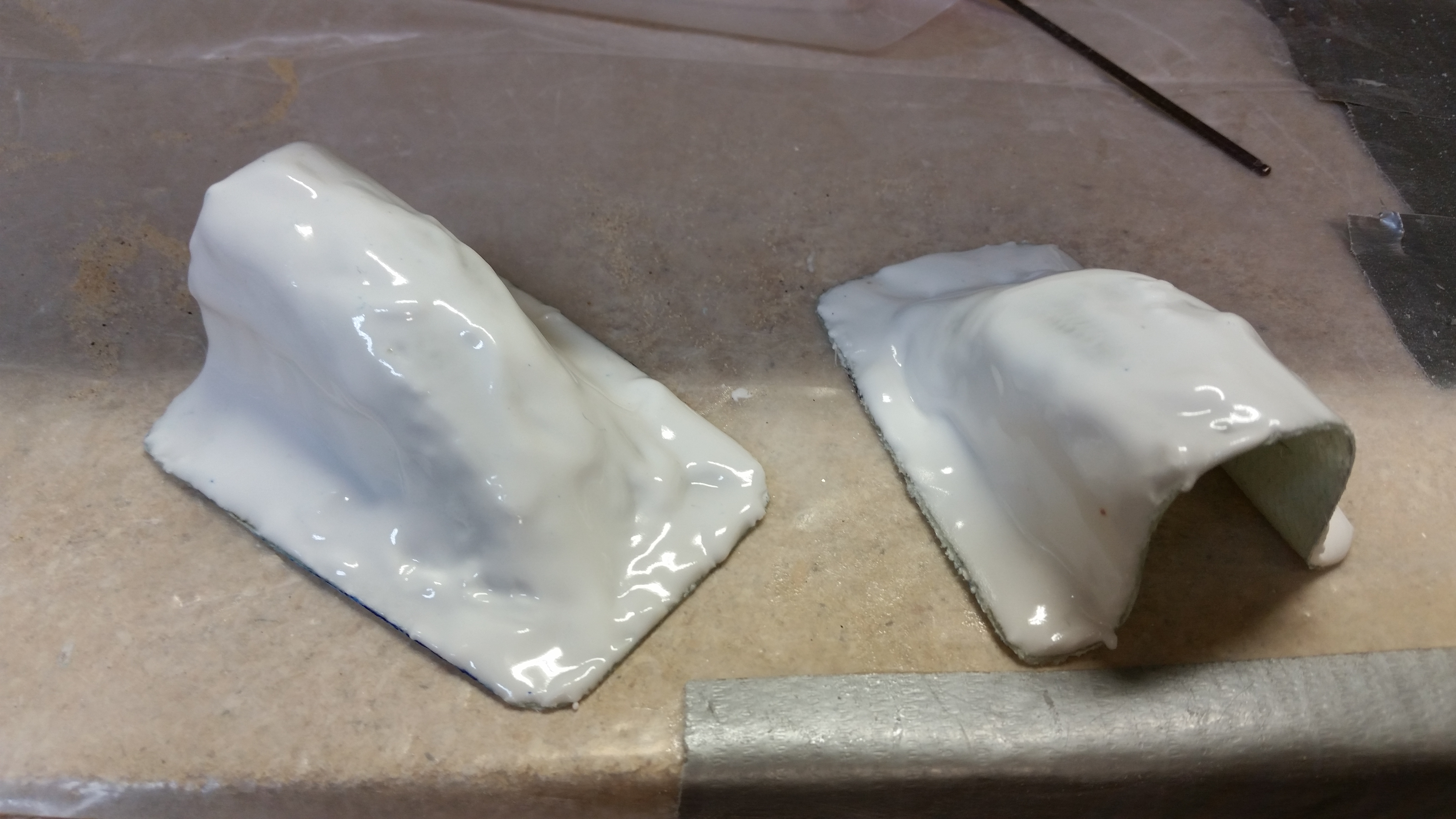
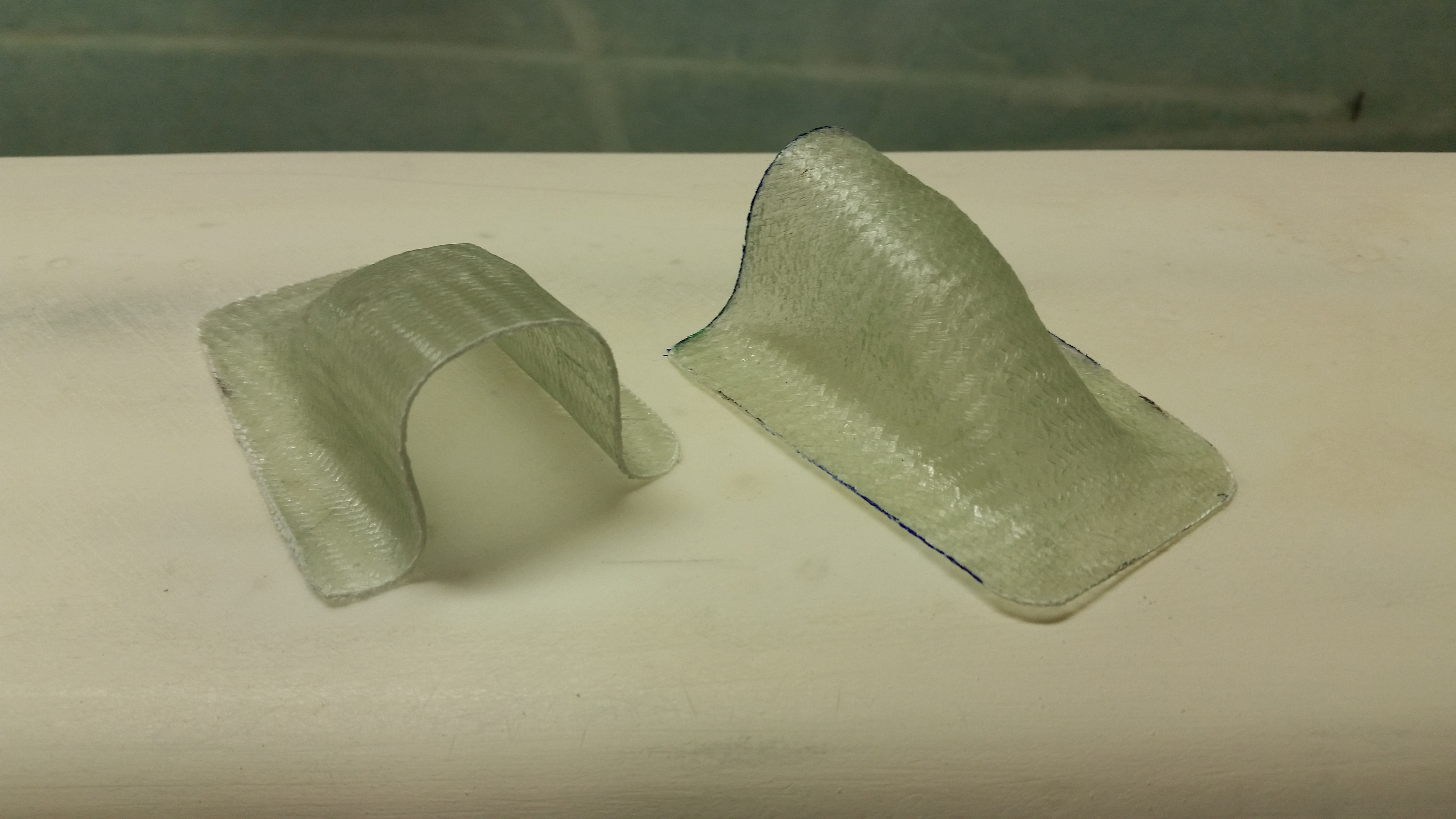
Since I had extra epoxy left over at one point–and hate wasting it–I finished shaping a piece of polyurethane foam into a mold for the elevator weight ice shield.  The pics below are immediately after I popped it off the mold and set it on the canard to see how it fit.

Ice shield - hot off the moldIce shield - hot off the mold

Here’s the same ice shield after I trimmed it.  I may change the shape later on, but it was a quick kill and for now I know that I have them done and ready for use.

Ice shield - trimmedIce shield - trimmed

I’ll keep working on the elevators and will start getting some pics so I can show you all what I’m working on.

In addition to working on the elevators, I also started researching the nose & nose gear build requirements so that I’m prepared to complete Chapter 13 in the next week or so.


Chapter 11 – Packing on Weight!

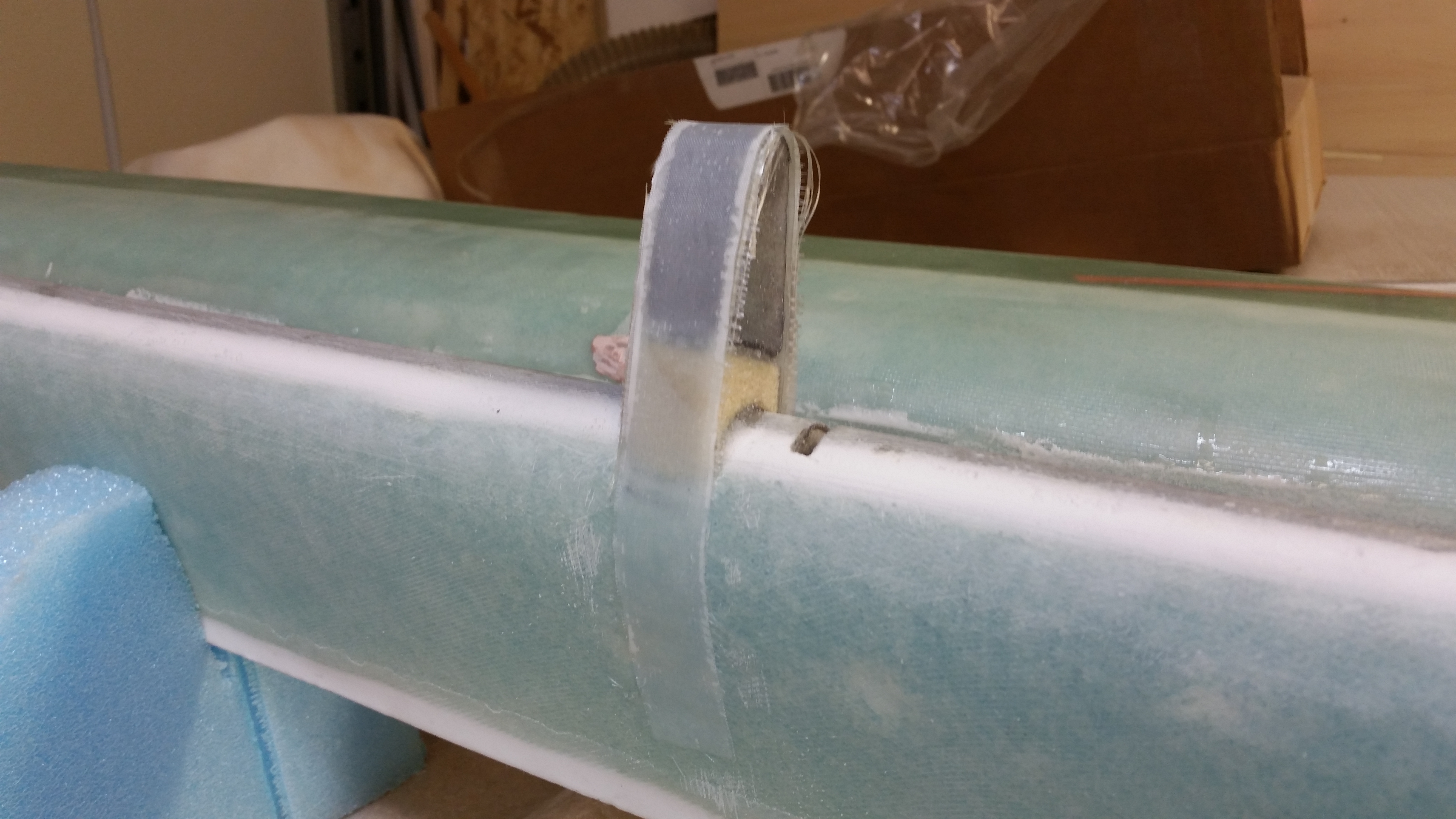
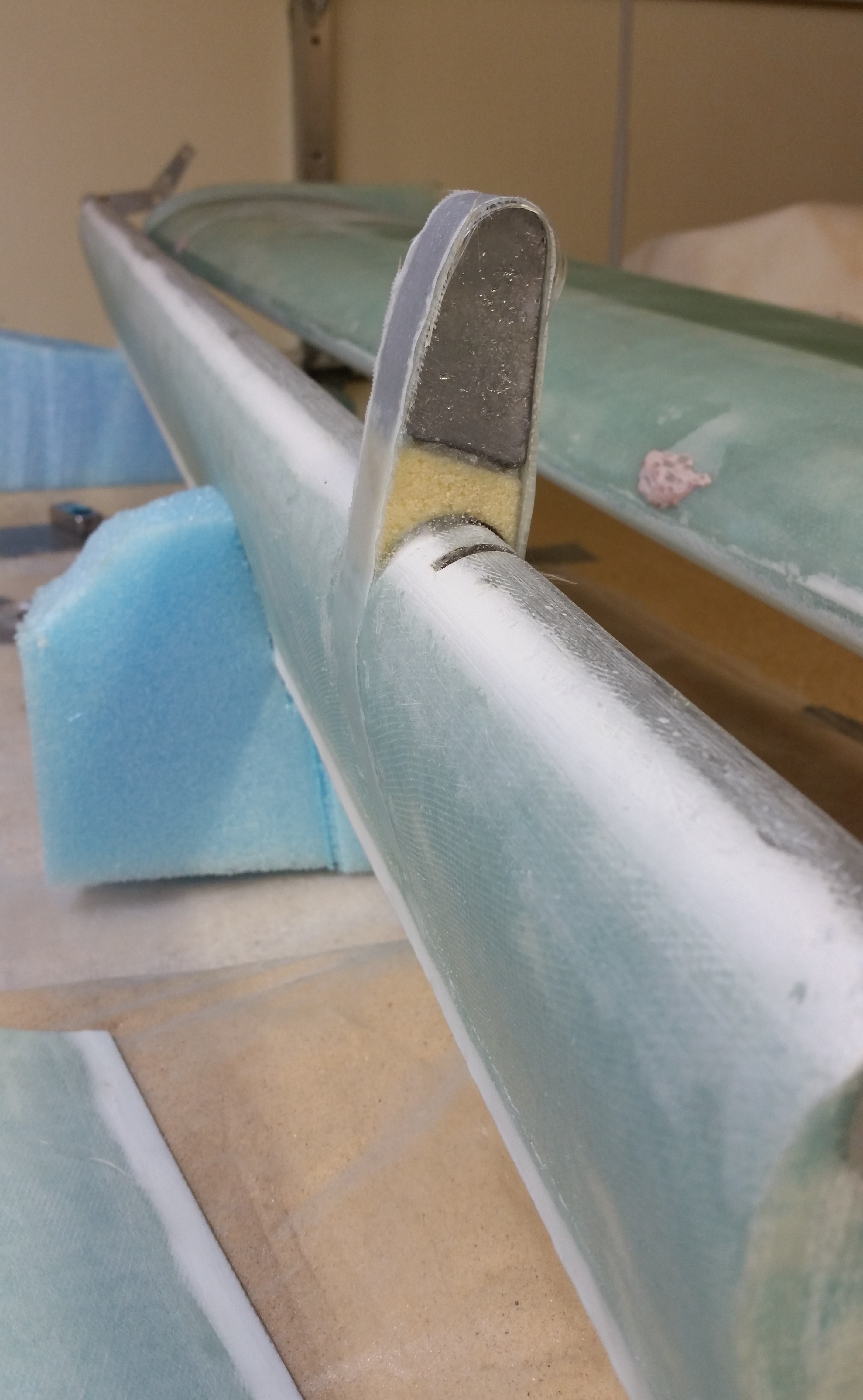
I started today by laying up the 11″ long 2-Ply strip of UNI around the outboard weight on the right elevator.  I peel plied it and moved on to the other elevator.
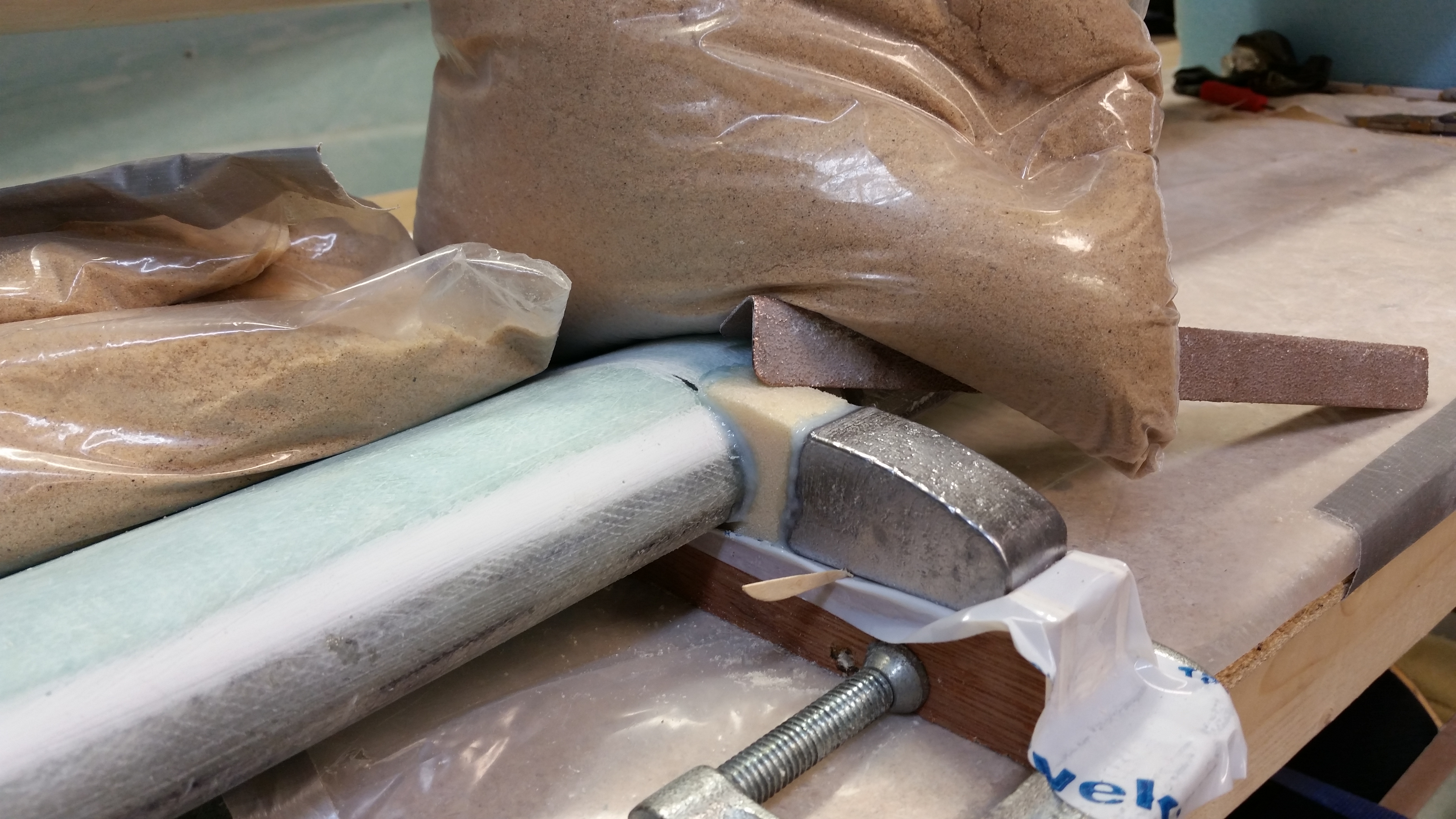
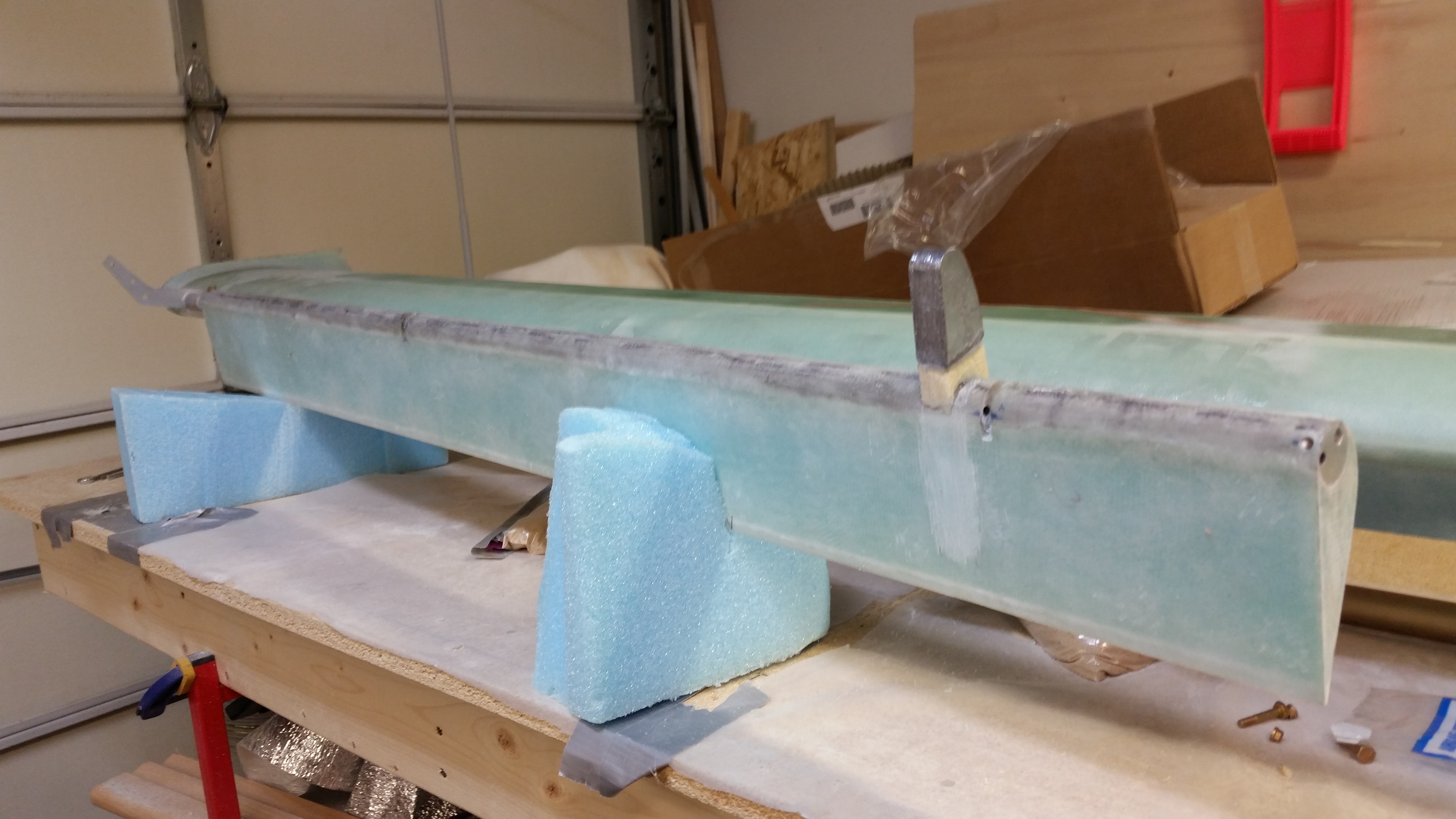
Right outboard elevator weight

Right outboard elevator weight

Just as I did on the right side elevator, I shaped the 6# yellow foam and floxed the outboard elevator weight setup to the front of the left elevator.

Left outboard elevator weight

While the flox was curing on the left-side outboard elevator weight assembly, I double-checked a few plans items and also drilled and mounted the right side INBOARD lead weight.  I also predrilled the first hole on the left side INBOARD elevator weight as well.

Not shown is some work I did on the inboard rib of the right wing to mount two click bonds for the aileron hinge bearing assembly.  After floxing the click bonds into place, I laid up 2 plies of BID over the click bonds, added a taped-up washer over each click bond and screwed them down to ensure a flat surface for mounting the aileron hinge bearing.  I should have a pic of this tomorrow.

By the time I finished some miscellaneous tasks, the flox on the left elevator outboard weight had cured enough where I could layup the 11″ long 2-Ply strip of UNI around the weight/foam arm.

If you look closely, the only real difference between the pics below is that the INBOARD elevator weight is mounted in the bottom pic.

Left outboard elevator weight

Left outboard elevator weight

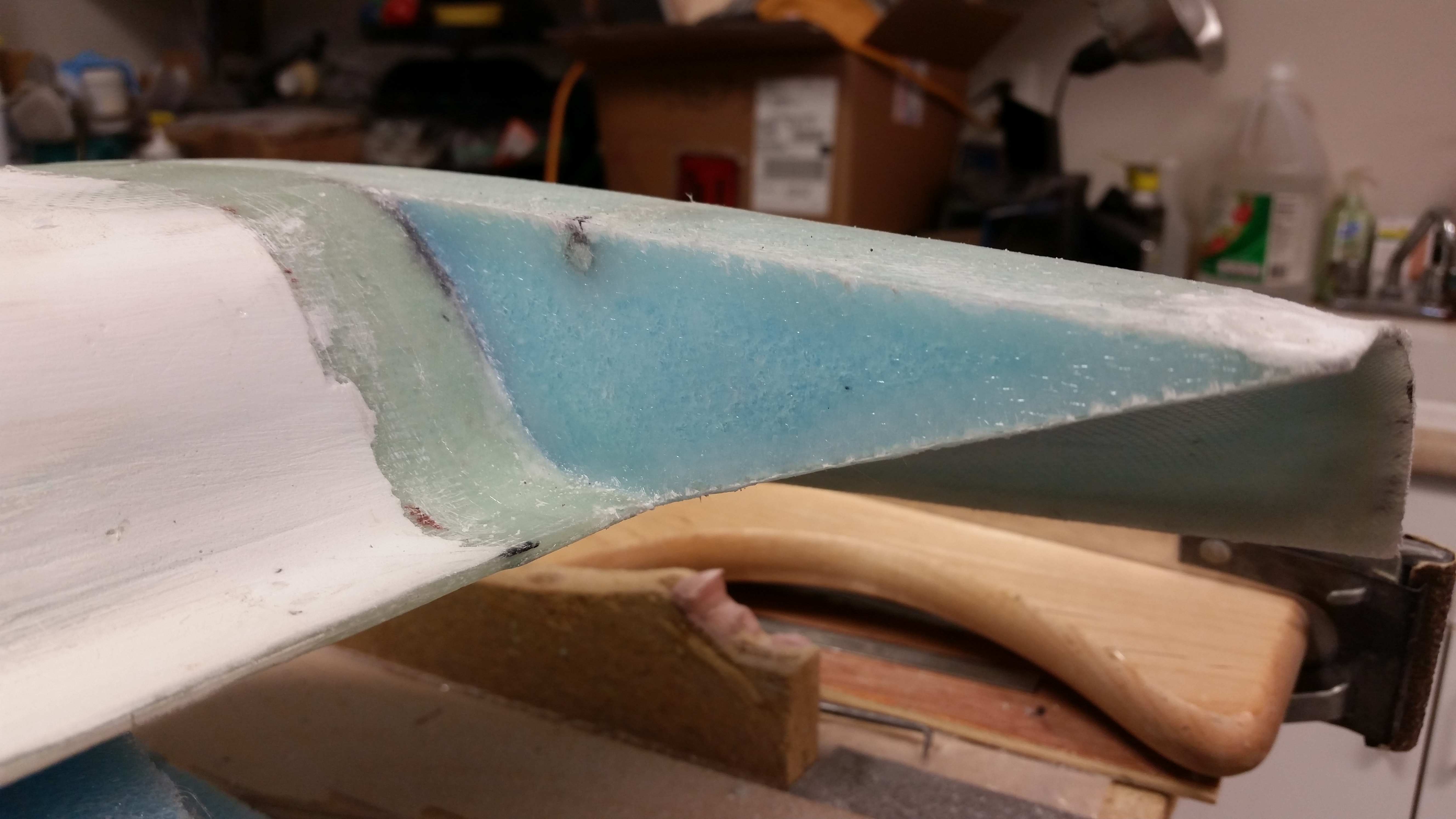
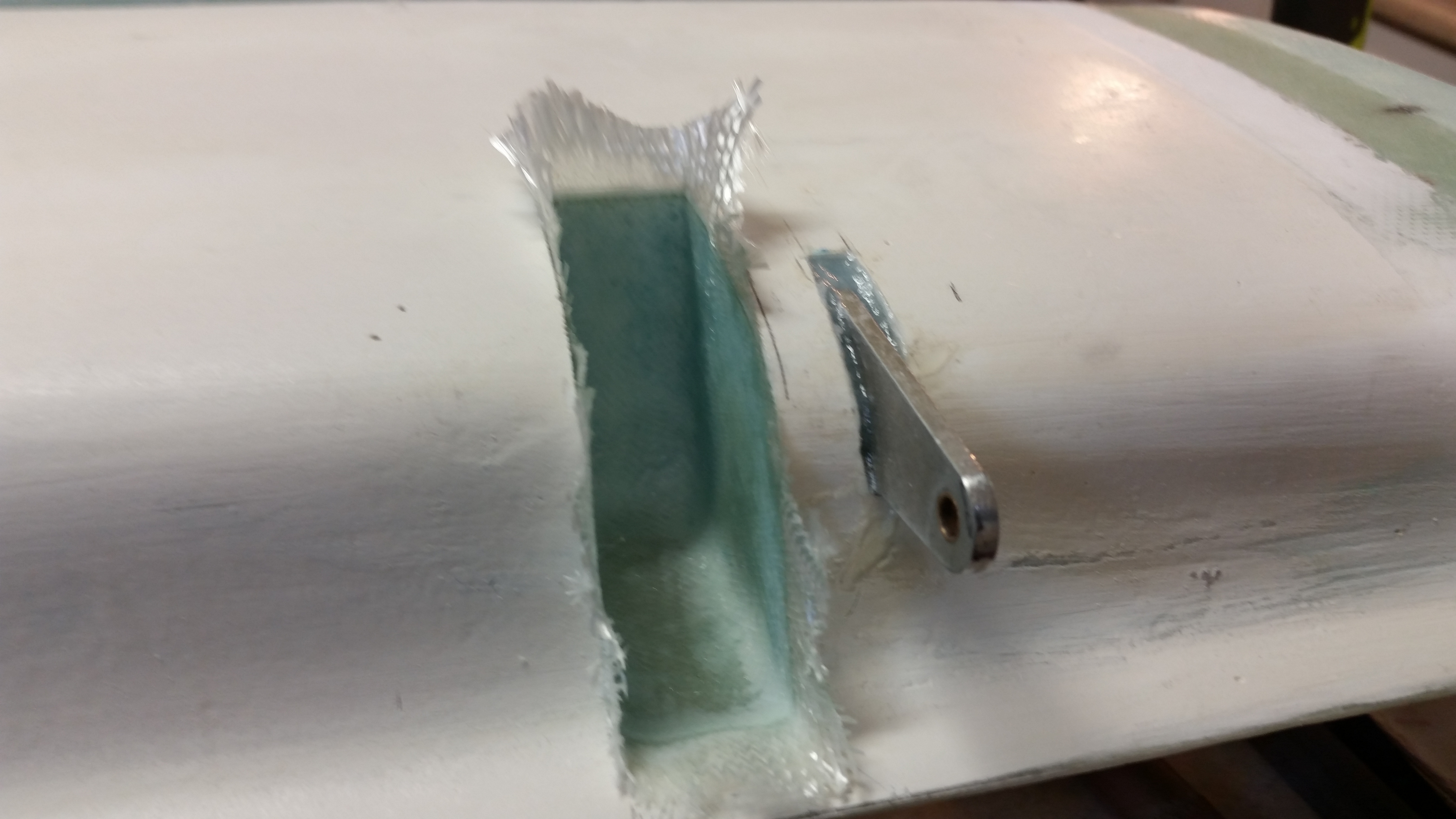
A few hours later I mocked up the elevators and made the embedded notch in the canard on the left side to allow clearance for the outboard elevator weight.

Notch in canard for elevator weight

And here’s the left elevator with attached outboard weight moving freely in/out of the notch on the canard.

Notch in canard for elevator weight

Next, I’ll be finishing up the notch on the right side of the canard, glassing them and cleaning up the outboard elevator weight layups.

Chapter 10 & 11 – More stuff

I started off today by knocking out the small 1-ply BID layup that sits just inside the swoosh tip on each end of the canard.  The Roncz canard plans states to create a flox corner around the perimeter of the foam and then layup the glass.

Personally, I would have preferred to have this “mini root rib” set back a little bit somewhat like the front inboard rib of the wing, with a little bit of an edge with the vertical wall of this layup sunk back from the edge, say a 1/2″ or so.  The problem is that this adds a little more time to the layup, and since I’m not sure if I would be adding to some kind of drag here or something else negative, I simply pressed forward with the plans version of this layup.
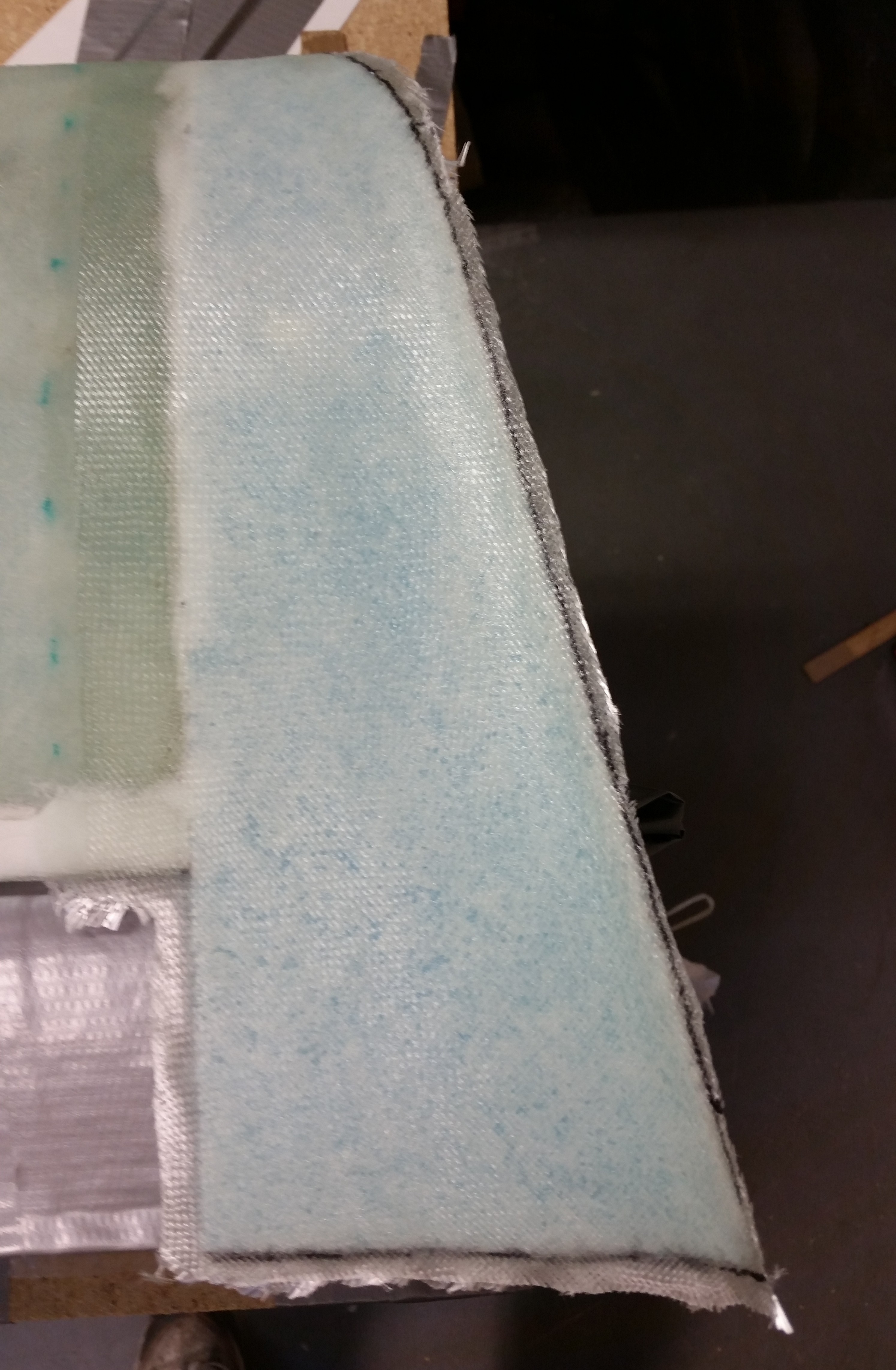
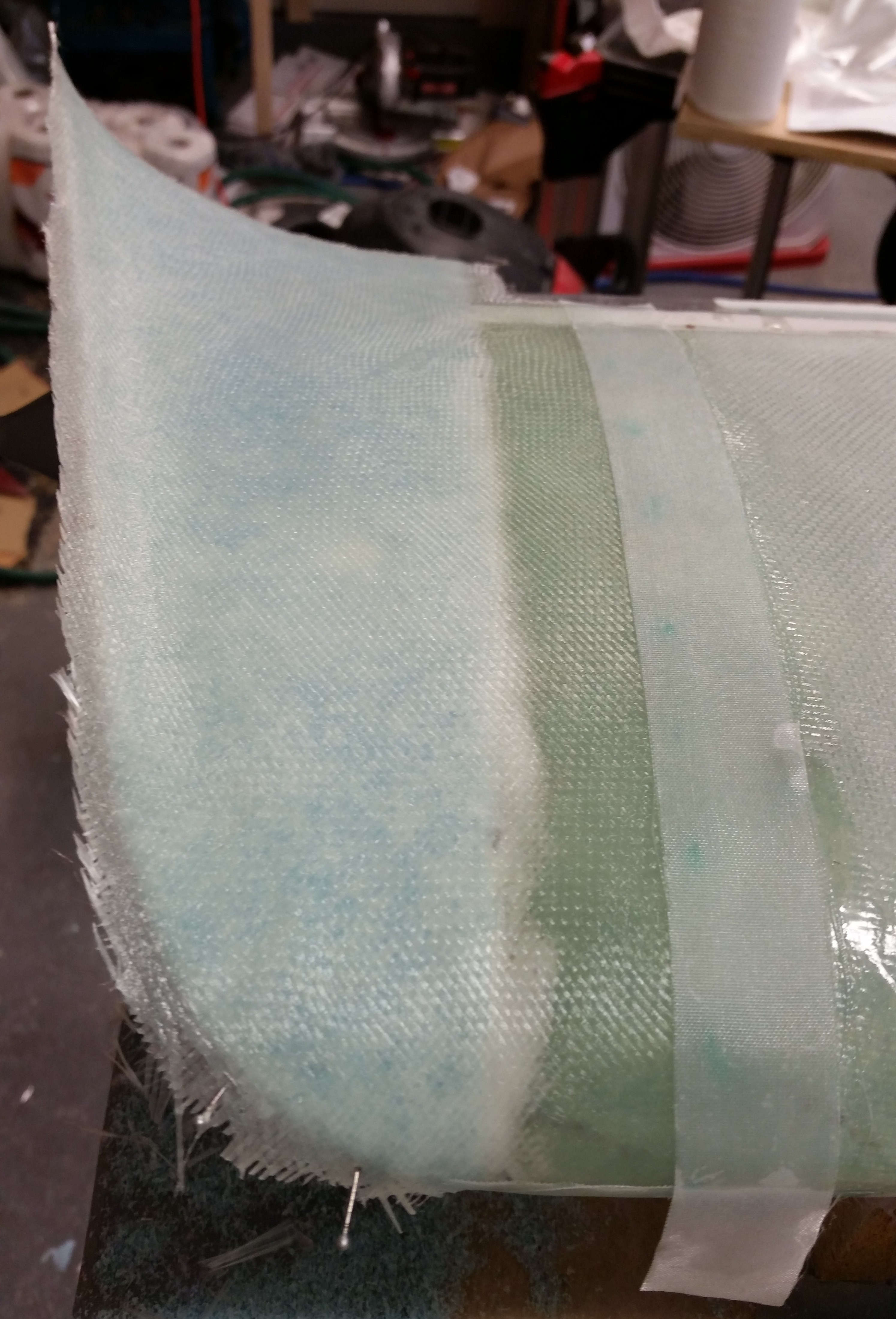
I cut a little trough around the hinge pin tube since there wasn’t a lot of meat or mass holding them into place on either side.   Also, once I put the flox in the corners, there was about 1.5 square inches of foam left so I simply finished out the tiny bit of flox I had left by using it to surface prep the foam vs. spending the time to mix up micro.  I KNOW!  The weight I added by such reckless building should be noted!  (Read: sarcasm!)

Inboard edge layup of right swoosh tipInboard edge layup of left swoosh tip

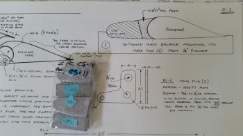
Next I focused on the elevator weights.  But before I actually installed any weights I weighed them to better match them up for total weight on each side.  All told there was a difference of 13 grams from one side to the other.  The blue tags on each weight is the actual weight in grams of that lead piece.

Elevator weights … weighed

I mocked up the right elevator to get all the parts synched up, and then started cutting the tough 6 lb. yellow foam.

Attaching outboard elevator weight

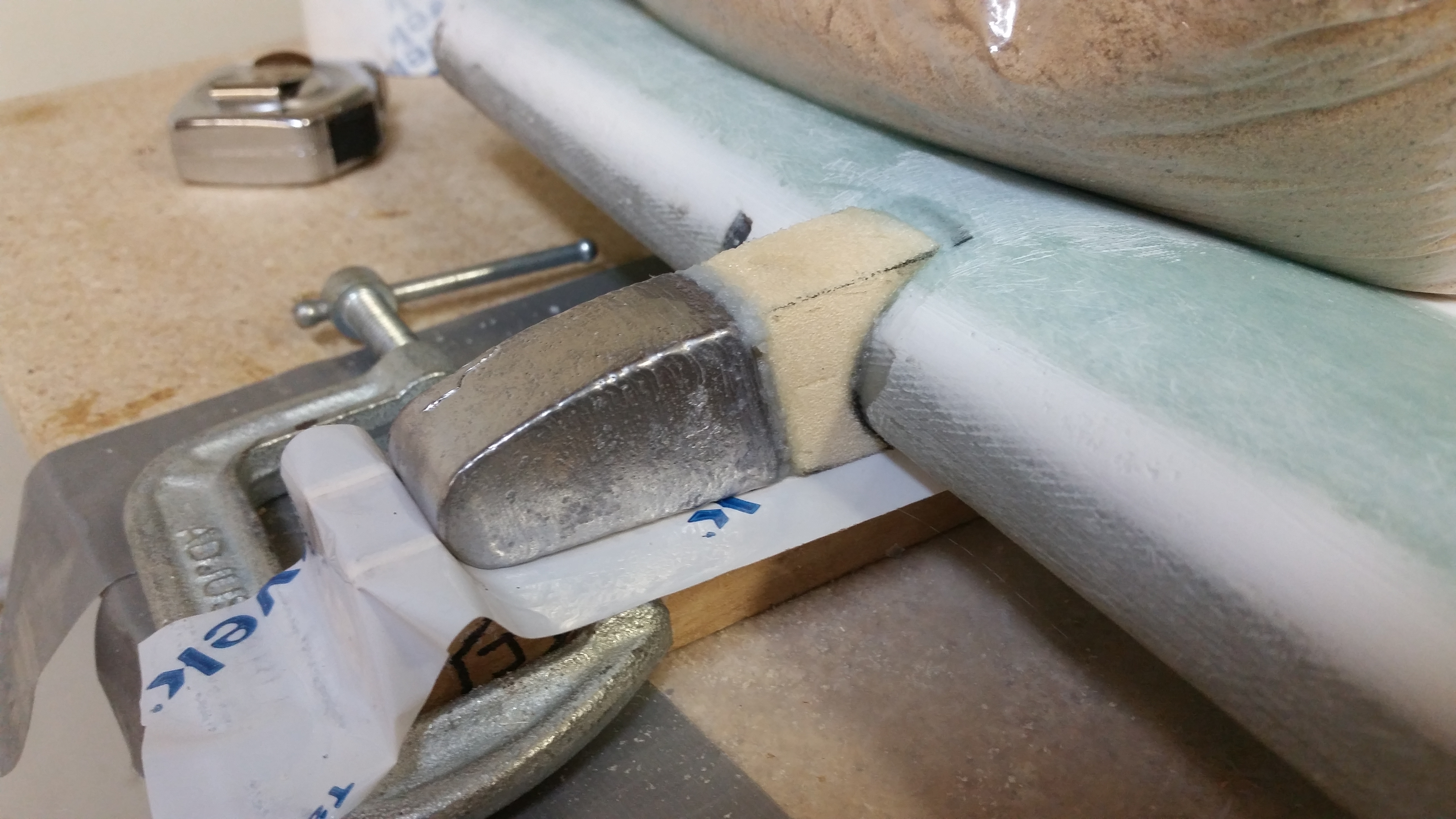
I put tape over the jigs to keep them clean and also enable removal of the weight assembly once it’s floxed to the LE of the elevator.

Prepping jig for outboard weight

I then prepped the elevator by giving it an extra good sanding in the area that will get the 2-ply strip of UNI holding on the outboard elevator weight.

OUTBD elevator glass prepped for weight

Once all the prep was complete, I floxed the elevator weight in place (I surrendered my 5-minute glue here in Virginia when I moved to Germany and never seem to get around to picking up another bottle).

Outboard elevator weight added

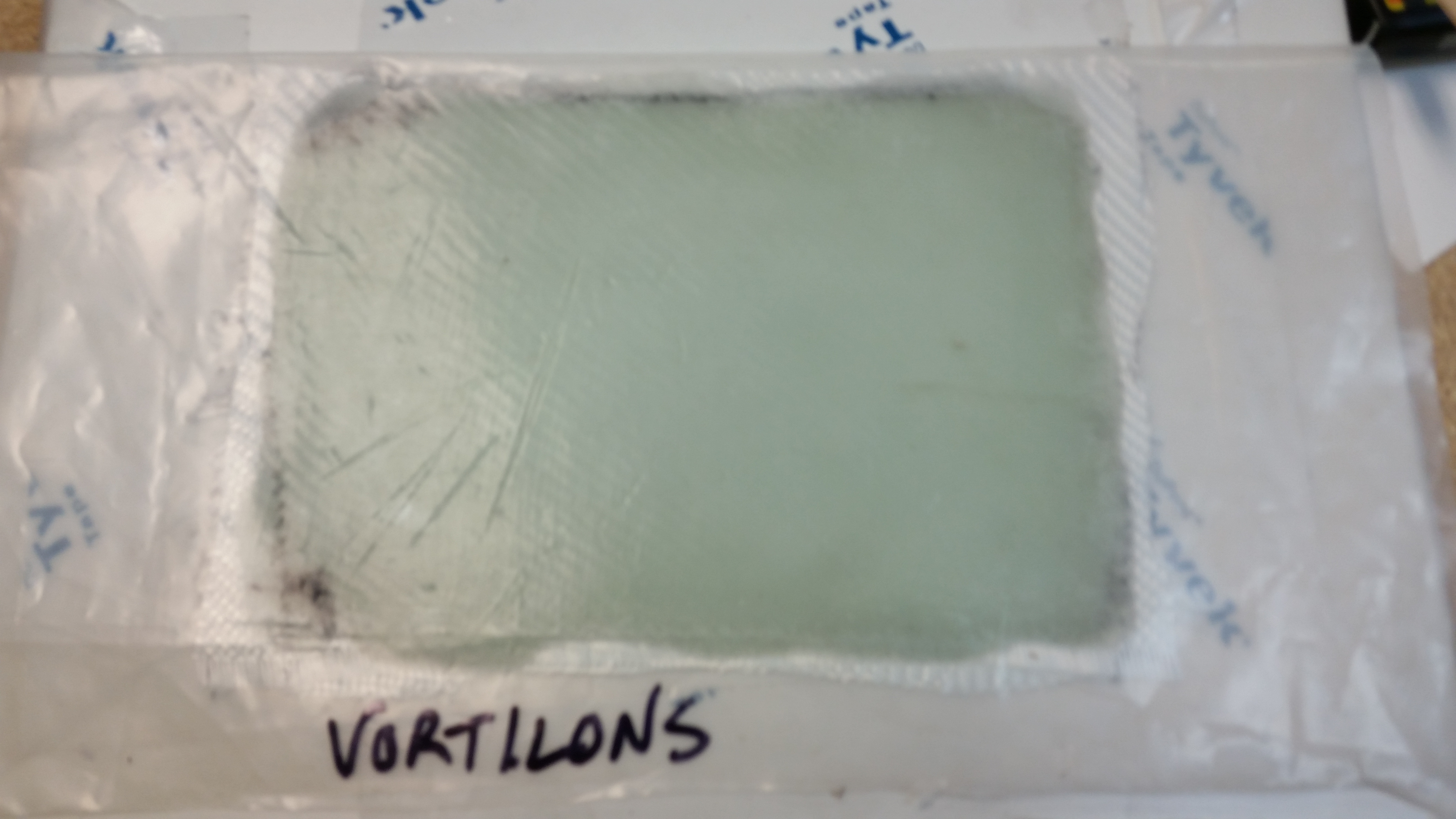
While the elevator weight flox was curing, I traced the remaining Vortilons onto the 4-BID sheet I had just laid up.  I then used a jig saw to cut them out (last time I did it by hand with a coping saw).  When I traced them I used a Sharpie to make thick lines, so they’re cut just a hair oversized.  I’ll dial in the exact shape when I go to install them.

VortilonsVortilons cut

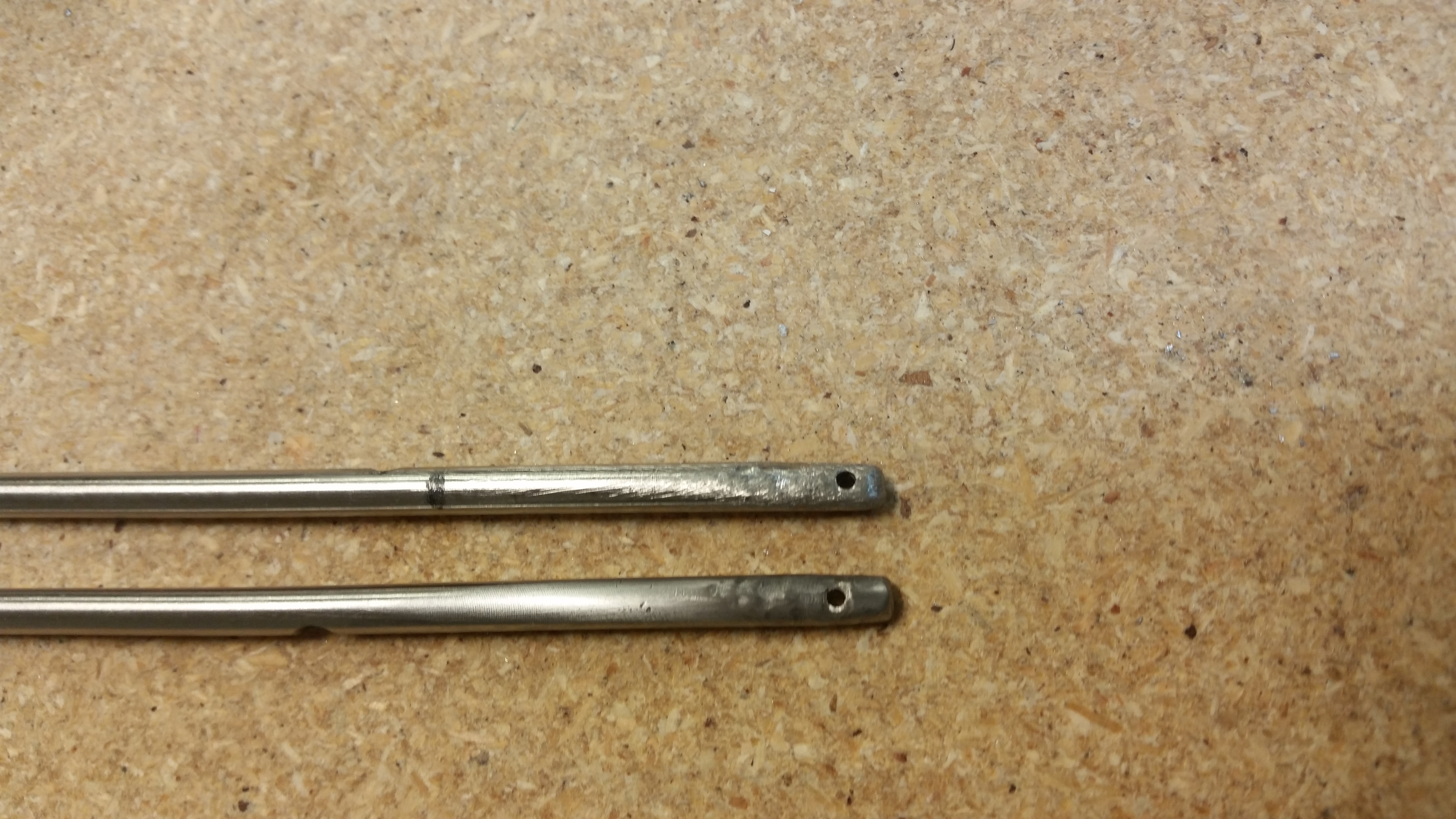
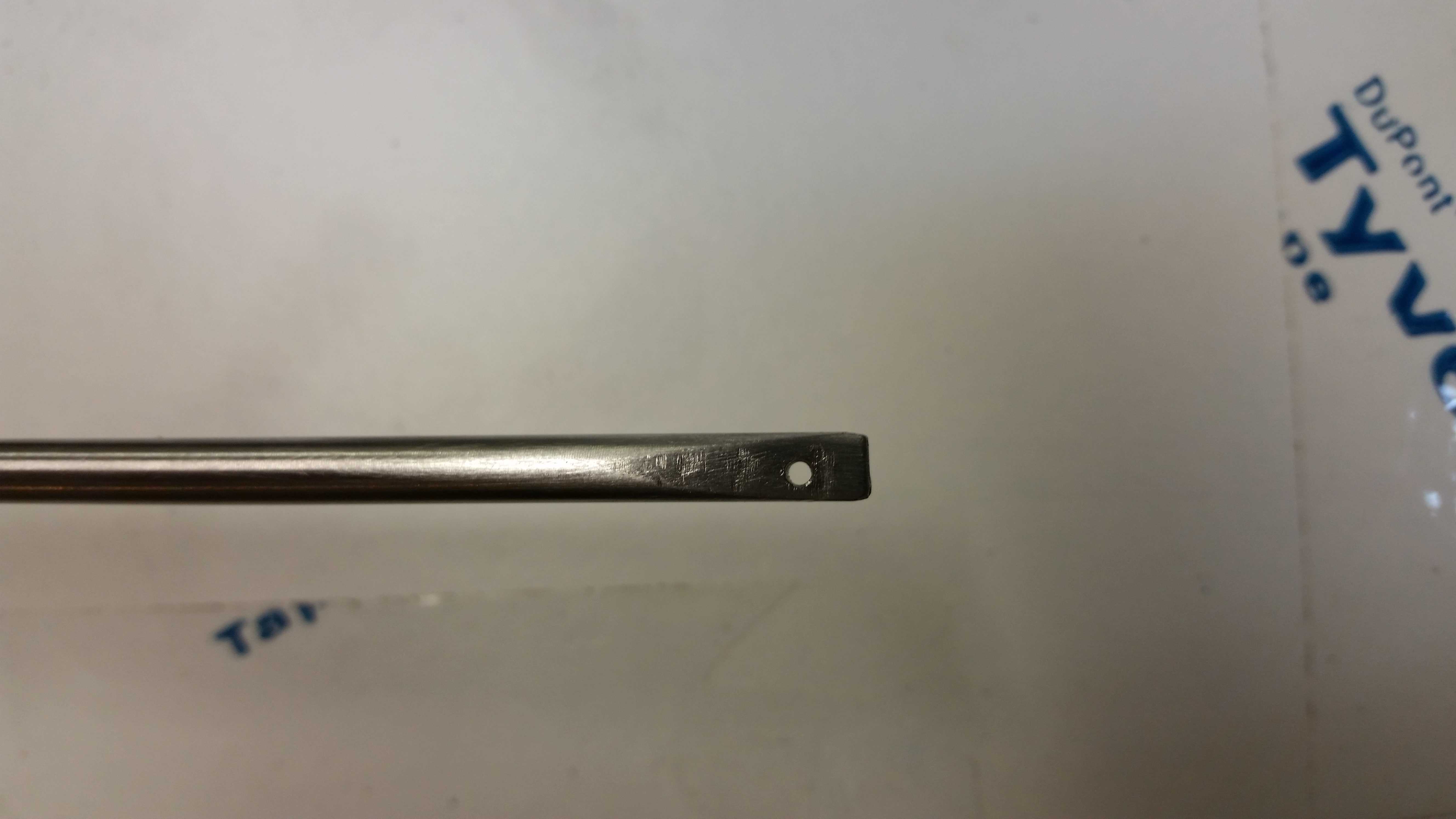
I then went back to work on the hinge pins.  The right pin needed to be cut shorter since I had already made the notch for set screw and didn’t like the way that every time I moved the elevator in a distinct up or down fashion the flat tip flagged out past the canard tip glass into the airstream.  I went back and looked at the plans again, and what I had looked pretty darn close to the diagram.  However, to be fair the plans do say to keep the tip out of the airstream.  So I simply cut it shorter & redrilled the 1/16″ hole more inboard.

Regardless, here are the two functional hinge pins.  I still have to clean them up to beautify them, but besides their need for a surface makeover they work as designed.

Hinge pins rough finished

Also, here’s a shot of inboard swoosh tip layup after I knife trimmed it.   The other side looks pretty much the same.

Inboard layup razor trimmed

As I was working on other stuff, I noted that this was the first time I had seen the canard in this state: elevators removed and the hinge tabs showing.  Something different so I snapped a pic.

Shot of hinge tabs on canard

The plan for tomorrow is to simply finish all the number of little jobs that will get Chapters 10 & 11 into the history books.  I’ll finish adding the elevator weights and cut the slots into the canard for the outboard elevator weights, glass those slots, etc.


Chapter 10 & 11 – Crushin’ It!

I started out today sanding the right side canard swoosh tip to shape.  Besides ensuring that you have a minimum of 0.4″ of glass to glass contact, the Roncz canard plans doesn’t really go into detail on glassing the bottom glass to the top.  So besides the glass to glass contact, I made a little trough all along where the two glass edges meet.  On the foam inside edge I ran a narrow bead of flox all along the edge to give it some strength before glassing it.

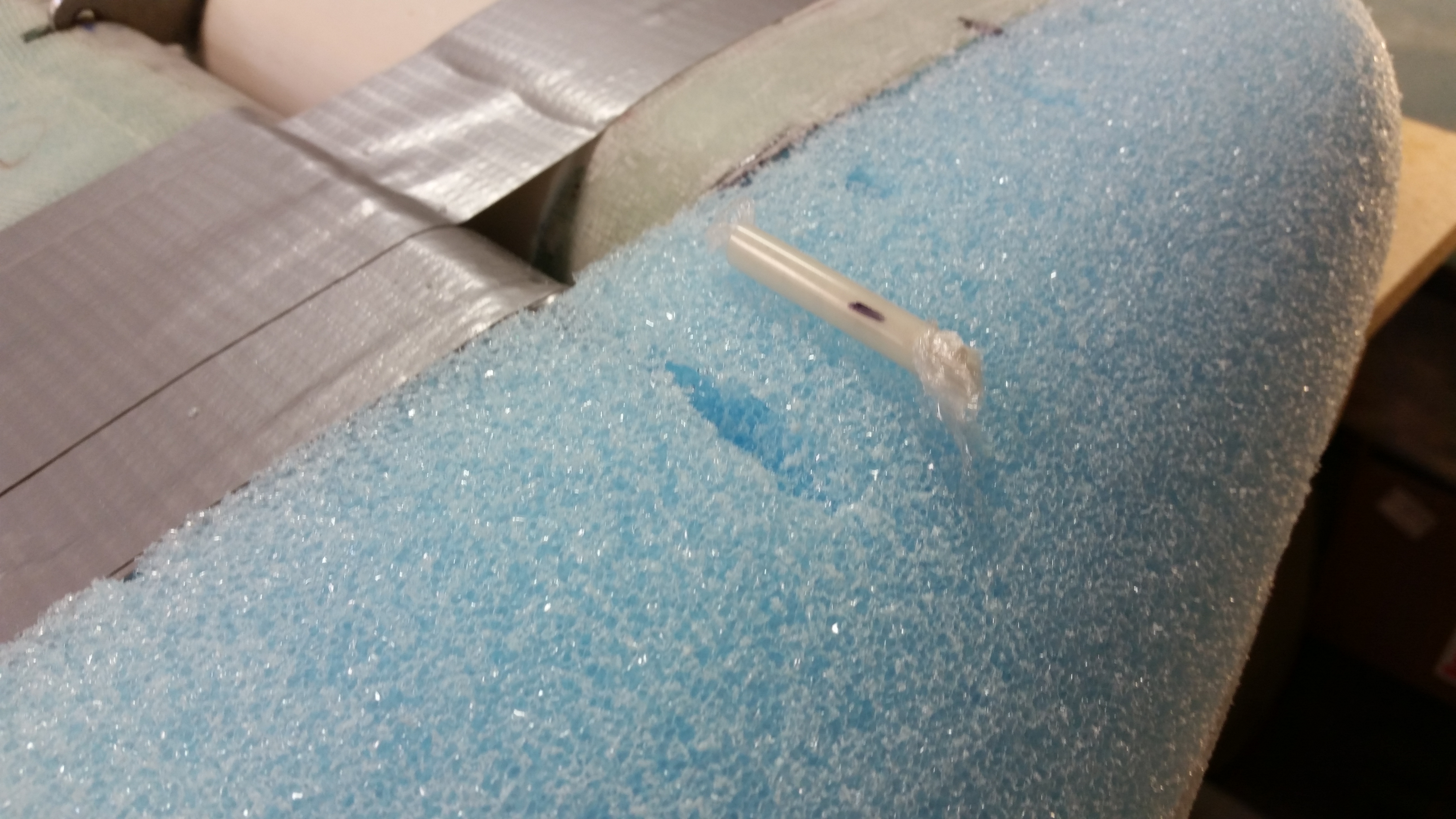
The actually sanding and shaping went a heck of lot quicker than the topside since there’s only so much you can do with the bottom side.  I tried out some 1/4″ OD Nylaflow and the 3/16″ ID seamed to work perfectly for the hinge pin conduit through the swoosh tip, so I cut a small piece, filled it with twisted Saran (plastic) wrap to keep the gunk out, and installed into the hole made by the original hinge pin.

The picture on the left shows the initial glassed swoosh tip, and the next two are a few hours later after I added dry micro to the edge after knife trimming the glass in its “green” stage (still tacky but definitely well on its way to curing).

In the evening after it had cured, I marked the hinge pin conduit and cut it out.

Right canard tip hinge pin hole

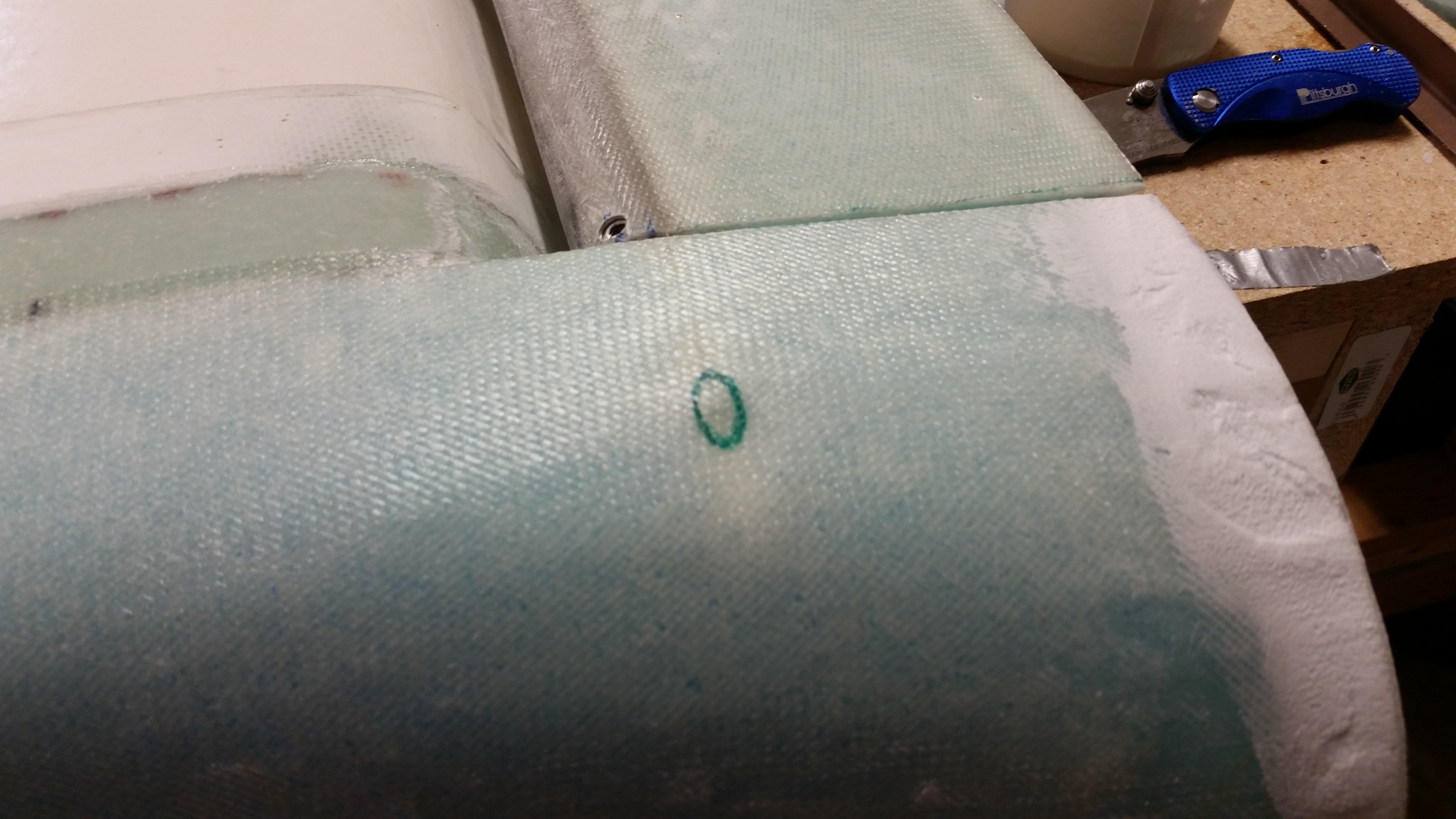
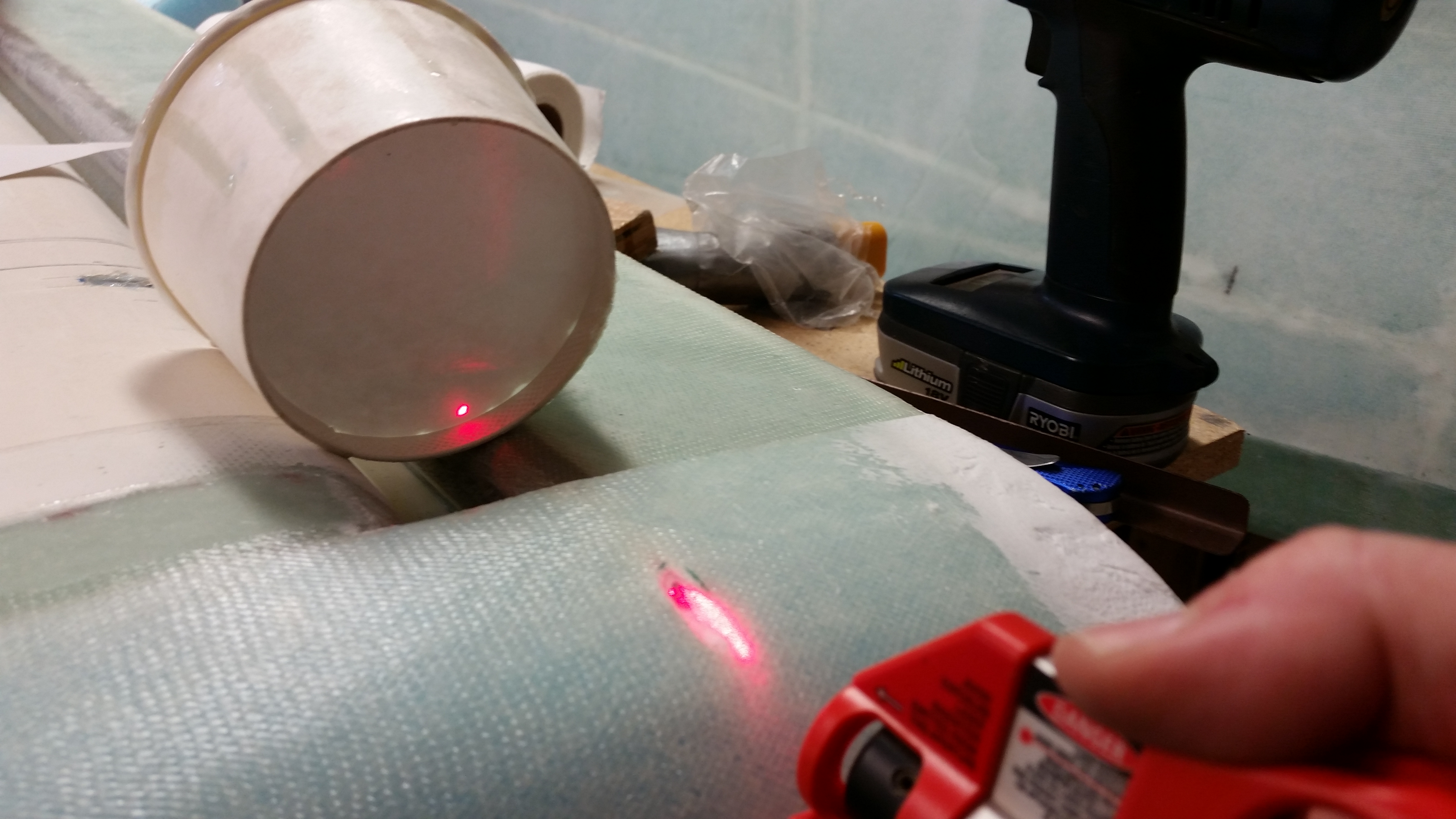
I drilled out the saran wrap and cleaned out the conduit with a 3/16″ drill bit.  I used a laser to make sure the conduit was clear.

Right canard tip hinge pin hole

Below are some random pics I took of the right-side canard swoosh tip with the canard in the normal upright position.

Here’s some better pics of they Nylaflow that I used for the hinge pin conduit.  This was right before I inserted it into the foam as I was glassing the lower left side canard swoosh tip.

Left swoosh tip hinge pin holeLeft swoosh tip - lower

Since I had the hinge pins out for glassing the lower swoosh tips, I grabbed one to work on the outboard end of it.  I shaped it with the Dremel tool, then I drilled a 1/16″ hole in it to allow for its removal later on with something like a scribe.

Right hinge pin - drilled & shaped

And here’s the lower left canard swoosh tip after I razor trimmed it and added dry micro.

Glassed lower left swoosh tip

Since I had used some leftover epoxy yesterday to make a set of Vortilons, today I wrote it into the work plan to finish the set for both wings.  Here’s they 4-ply BID layup for two more sets of Vortilons.

#2 vortilon layup 6"x 8" 4-ply BID

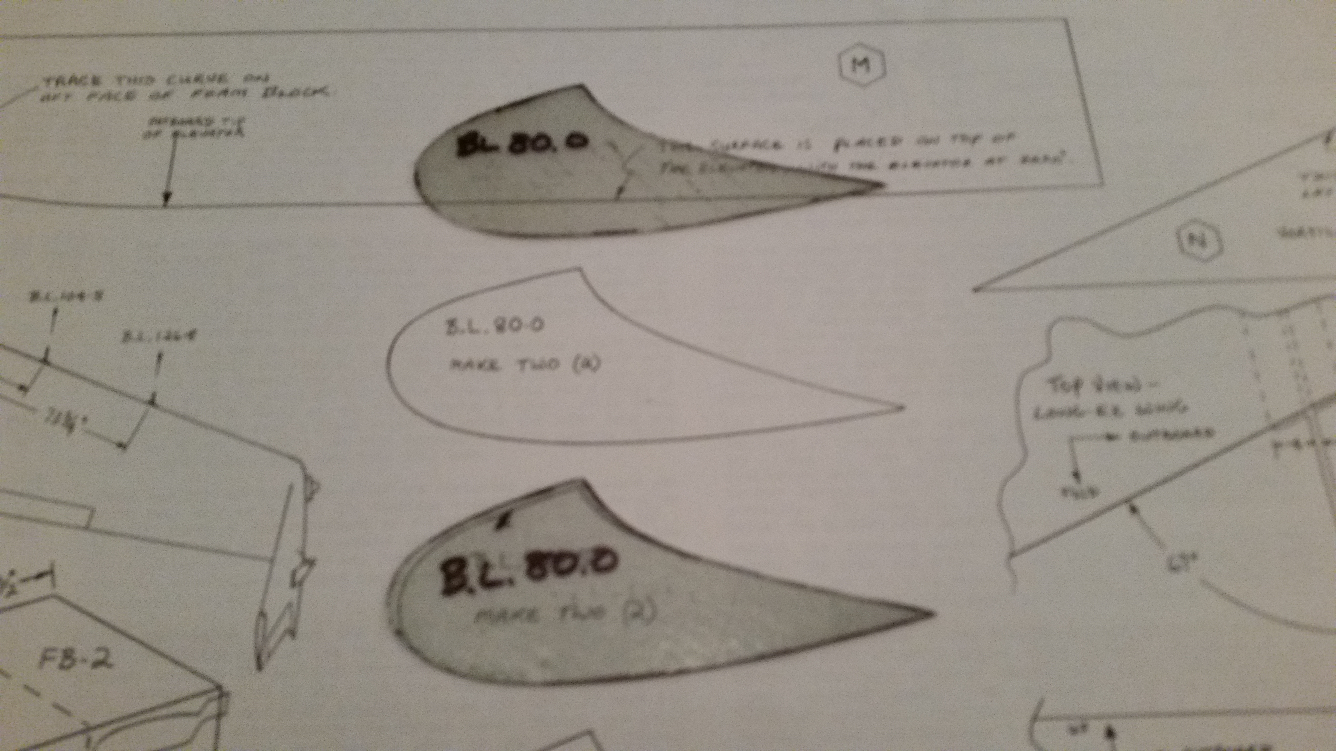
And here are the initial two that I cut from the glass I laid up yesterday.  These are the largest of the 3 sets of Vortilons.

BL 80.0 Vortilons cut

Finally, here’s the hinge pin hole from the left side swoosh tip.  Since the glass was still in the green stage, I took the opportunity to razor cut the whole for the hinge pin conduit.  You can still see the quite tacky micro in the lower photo.

Left canard tip hinge pin holeLeft canard tip hinge pin hole

Next I’ll continue working on the swoosh tips and the elevators to get the entire canard & elevator combo completed.  There are no major tasks left after the swoosh tips were glassed, but there sure are a myriad of small tasks that need to be accomplished before I can call these officially done.


Chapter 10 – Swooshin’ It!

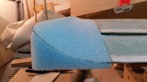
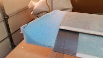
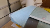
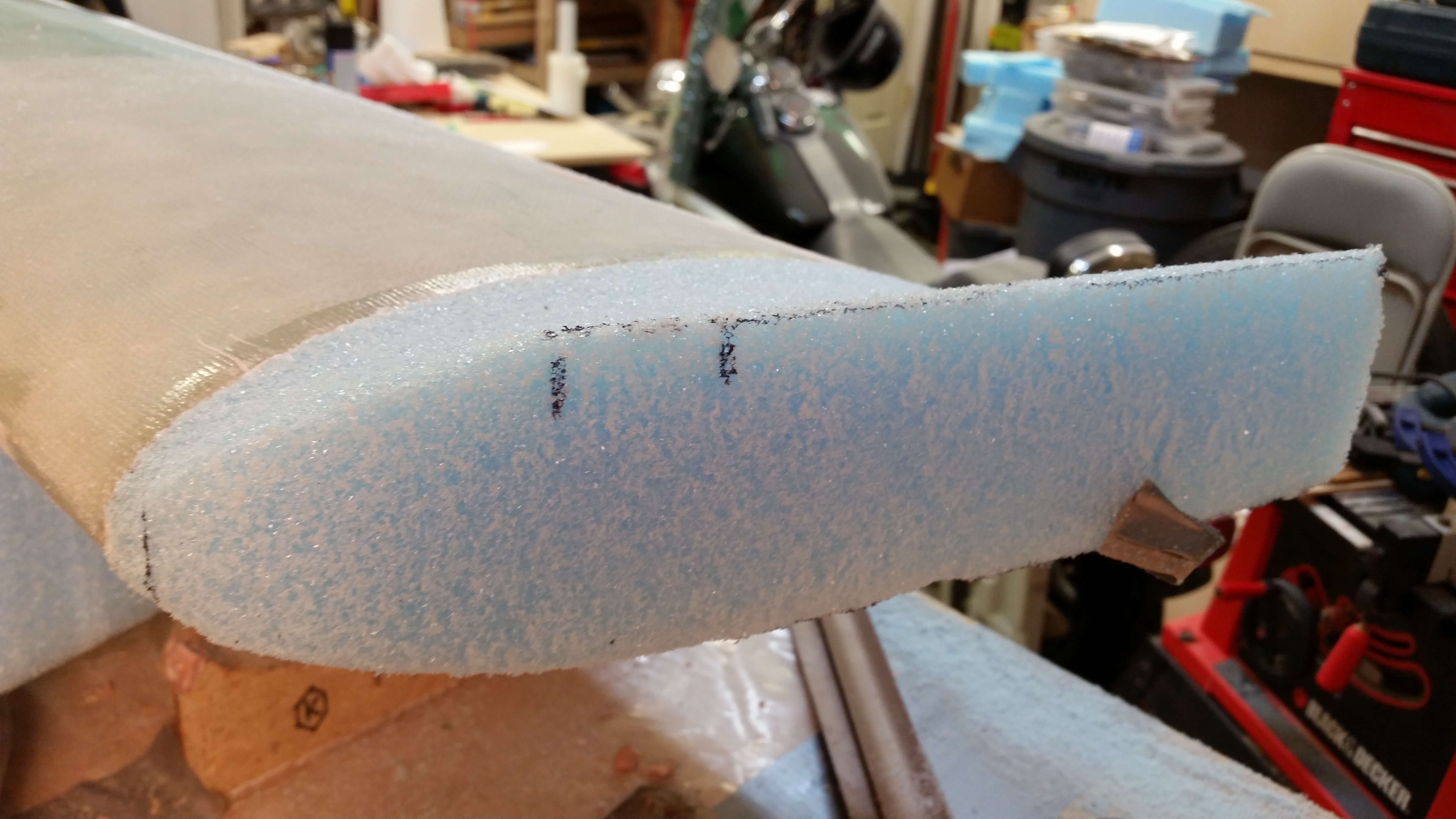
I started out early this morning carving the “swoosh” tips out of the blue foam that I micro’d to the canard last night.  This is one of those very distinctive exciting steps in building a canard aircraft since, obviously, these swoosh tips make a stylistic statement about the bird.  Also, since Roncz canards are all built with the same plans there’s not that big of a difference in the “I’m cool” department . . . the scenario is more along the lines of, “Hey, check out all these nice turned up tipped Roncz canards here, and mine look like crap!” Ha!  That’s what I’m trying to avoid!

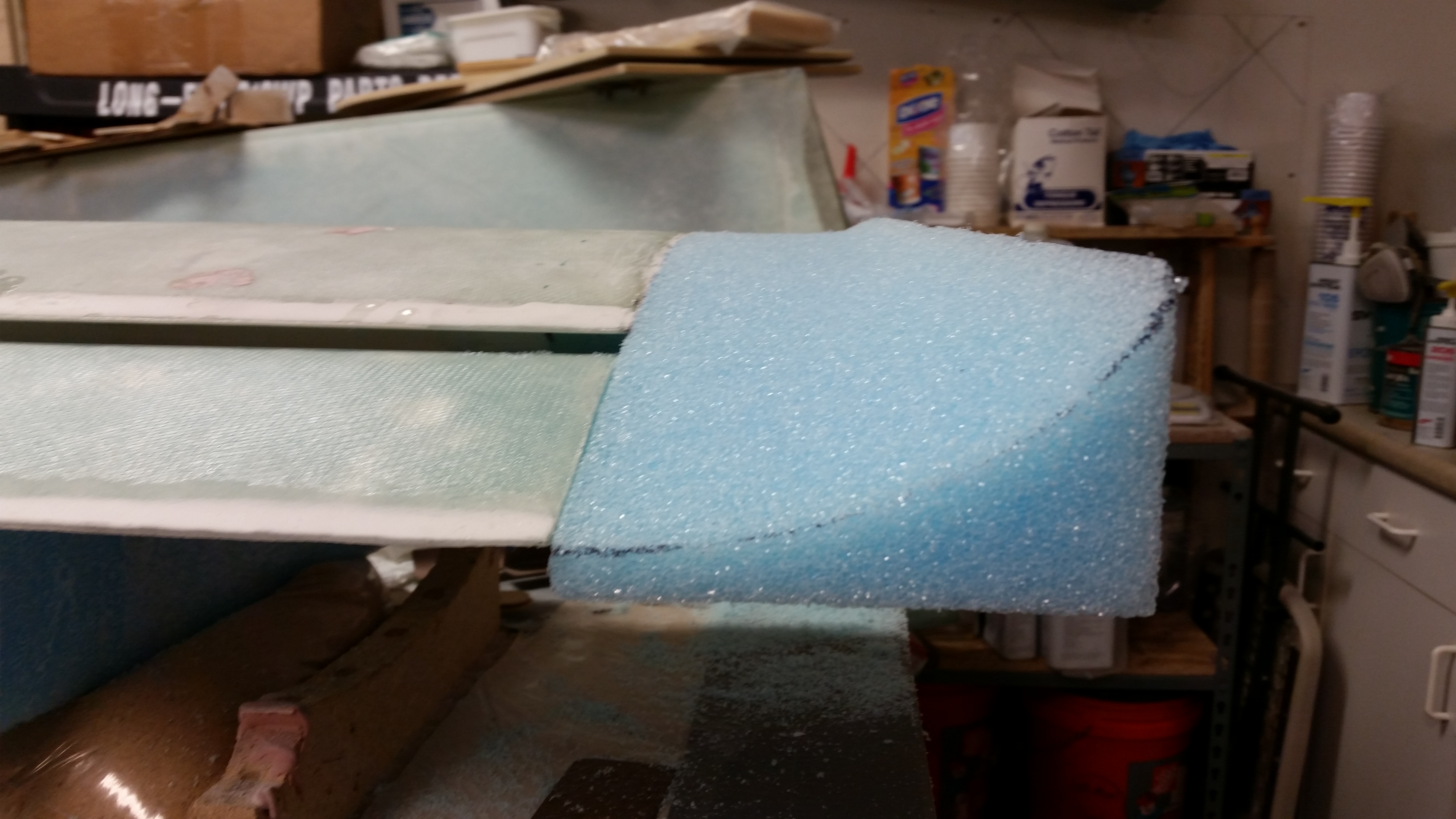
Thus, I did exactly what the plans stated and started out slowly.  BTW, I grouped all the pics in a series per the angle of the camera shot so you can see a progression of the foam taking shape.

Shaping Right swoosh tip

I think the biggest Aha! moment was realizing that the toughest part of this whole carving exercise is the first 3-4″ on the LE side.  Wow!  What a head-scratcher as far as, “What the heck do I do here?  And what do I really what this thing to look like?”  I went back upstairs at this point (after having carved away on the front side) to look at the large pics in the Roncz plans and check out a half dozen websites where I knew I could find some pics of Roncz canard tips.  Talk about one area that I never gave much thought to, even as I started carving!  Another crazy thing is that you really don’t know exactly how good the top swoosh tip contour is going to look until after the bottom is finished.

Oh, well.  After getting a better mental picture I went back to carving.  I will say that if I had known what I know now, I would have had a better plan for that front area.  I’m happy with how it turned out, but I would have gone in just a slightly different direction if I hadn’t starting carving without an idea of what the front LE area transition should look like.

After doing my best to make sure that I had a smooth surface with good transitions, I pulled the trigger and glassed the top skin of the right swoosh tip with 2-plies of UNI biased in the typical 30° to each other.

Some rear views . . .

Right swoosh tip glassed - UNIRight swoosh tip glassed - UNIAnd some top views . . .

Right swoosh tip glassed - UNIRight swoosh tip glassed - UNI

A number of hours later after I knife-trimmed it with the Fein saw, and then sanded the edges.

Right swoosh tip glassed - UNI

Right swoosh tip glassed - UNI

To show you my original thinking, take a look at the template to the right in the pic below. That’s how I had originally envisioned the nose of the swoosh tip.  That quickly transitioned into an insane template that would have been better described using a NASA 3D modeling program.  I thought maybe a working knowledge of geometry may come in handy here . . . oh, no, folks!  We’re talking calculus & quantum physics for this project!

Why?!  Well, in Burt’s sadistic command, “form to a pleasing shape” I can see where it may not be a big deal.  Except in this case you have to make a mirror of that which you just free formed into a “pleasing shape!”

Swoosh tip template

So here’s round two of “forming into a pleasing shape.”  Obviously side 2 is all about replicating side 1 . . . some heavy stuff here my friends!

I started in quickly and got the left side canard tip to pic #1 in about 5 minutes, and to pic #4 in about 20 minutes.  But after I got the basic shape, I then kept going back and forth from one side of the canard to other measuring distance, elevation, slope, etc. to get this side as close to the other side as possible.  I guess the saving grace is that these sit about 11 feet apart from each other on opposite ends of the canard, so it obscures any slight differences.

Nonetheless, at the end of another 20 minutes or so, I felt like I had a good mirror replica of the right side swoosh tip.

I prepped the left side canard swoosh tip for glassing.  One thing of note is that the back to top corner was a little dinged up, so I added a small buttress to keep the aft skin layup straight.

Left side canard "swoosh" tipLeft side canard "swoosh" tip

I then laid up the top of the left side canard swoosh tip with 2-plies of UNI just like the right side.  I will say that after I was finished I had an issue with the shape of the left canard tip. You see, after I put the wood support piece in place I needed to finish sanding the outboard top edge to a fine point to get the shape to match the other side (this was before the layup).  Well, I used my Perma-Grit half moon sanding toold which–unbeknownst to me at the time– caused a much sharper radius in the foam right at where it made it’s final turn up at the edge.  It’s basically like comparing the curve of a “C” like I had on the right side compared to the shape of a “U” which I had now on the left side.  Again, this was all occurring in the very outboard upturn, and all within about 3/4″ of an inch from the edge.

After I glassed it, I compare it to the right side and that outboard upturn was staring me in the face.  Since I hadn’t feathered that final removal of foam for the sharp edged upturn, it was showing up much more prominently after glassing.  To be clear, if this was the way both sides looked, it would be fine and not something that looks like a mistake.  It was simply a different style, or look, than what I had on the right side.

After a couple more double takes, and comparing it to the other side again, I couldn’t take it.  I peeled back the UNI, grabbed the 2″ diameter PVC tube sander (that I had made for shaping the swoosh tips) and simply feathered the micro-covered foam down to “a pleasing shape!”  I then made sure it was what I wanted and matched the other side, and simply laid the UNI back into place and squeegeed it flat.  It all took maybe 5 minutes and I was then infinitely happier with the outcome of the left side swoosh tip layup since it flowed with a nice gradual curve from base to tip just like the right side.

Left side canard "swoosh" tip glassedLeft side canard "swoosh" tip glassedLeft side canard "swoosh" tip glassed

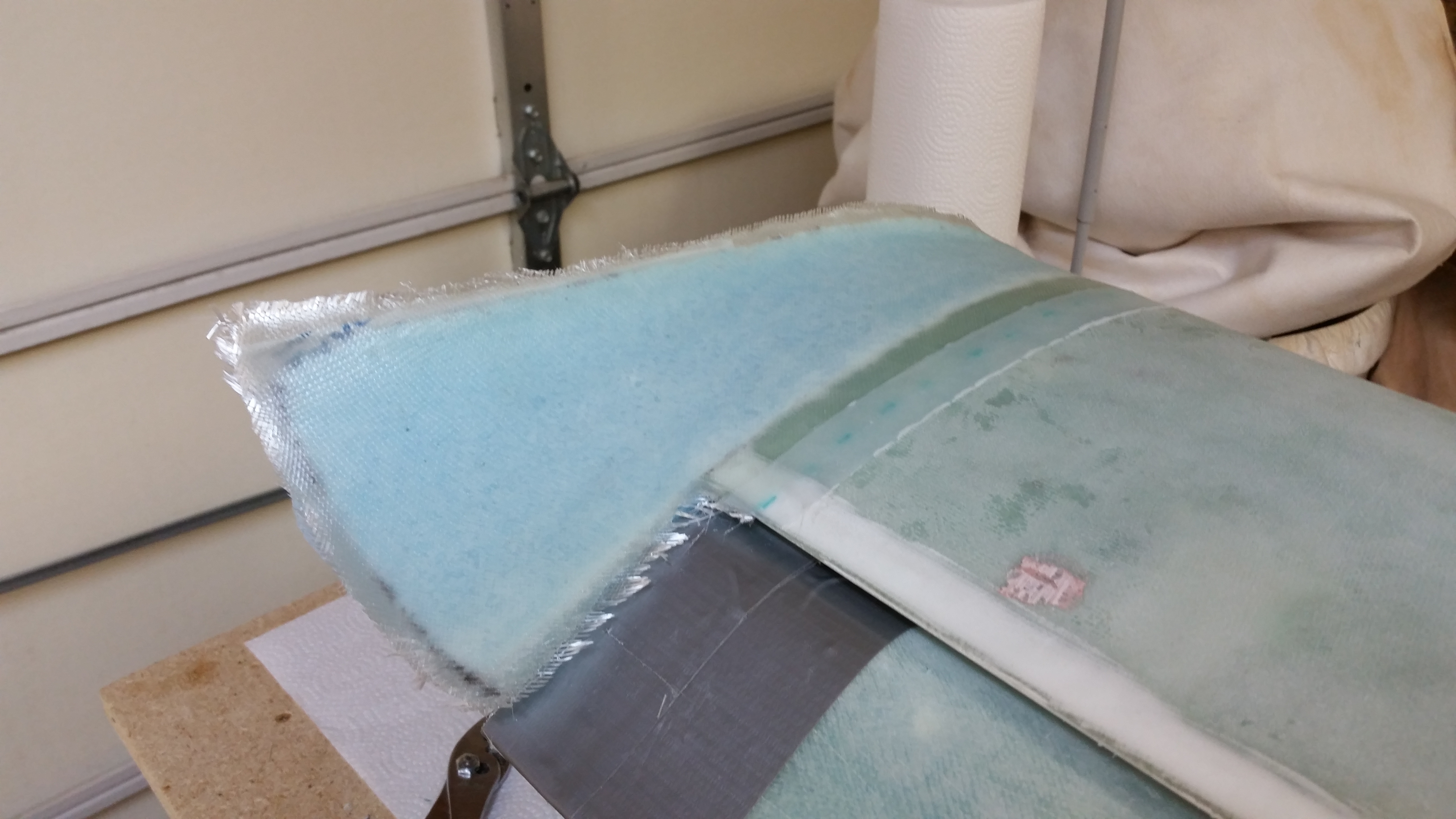
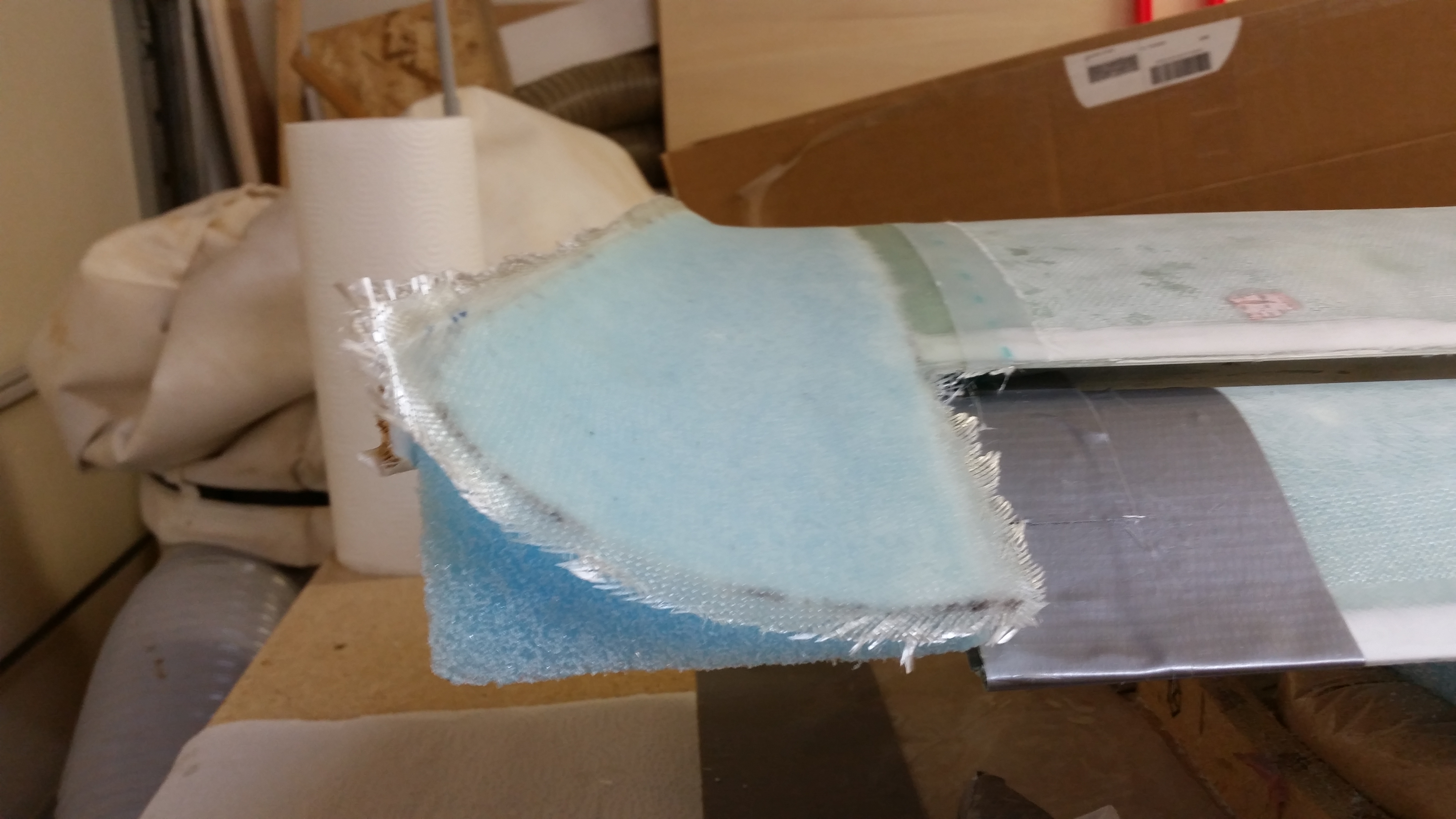
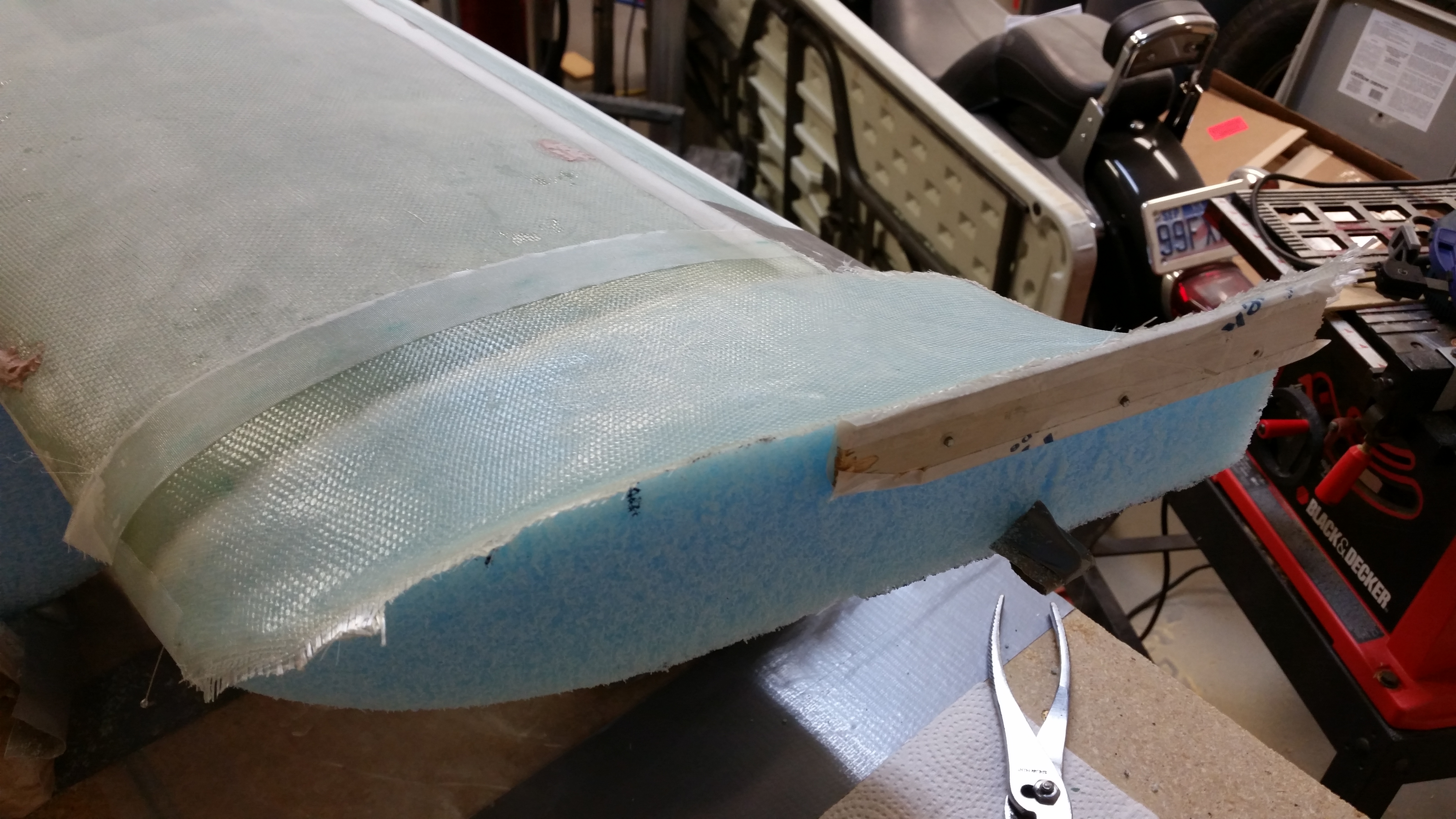
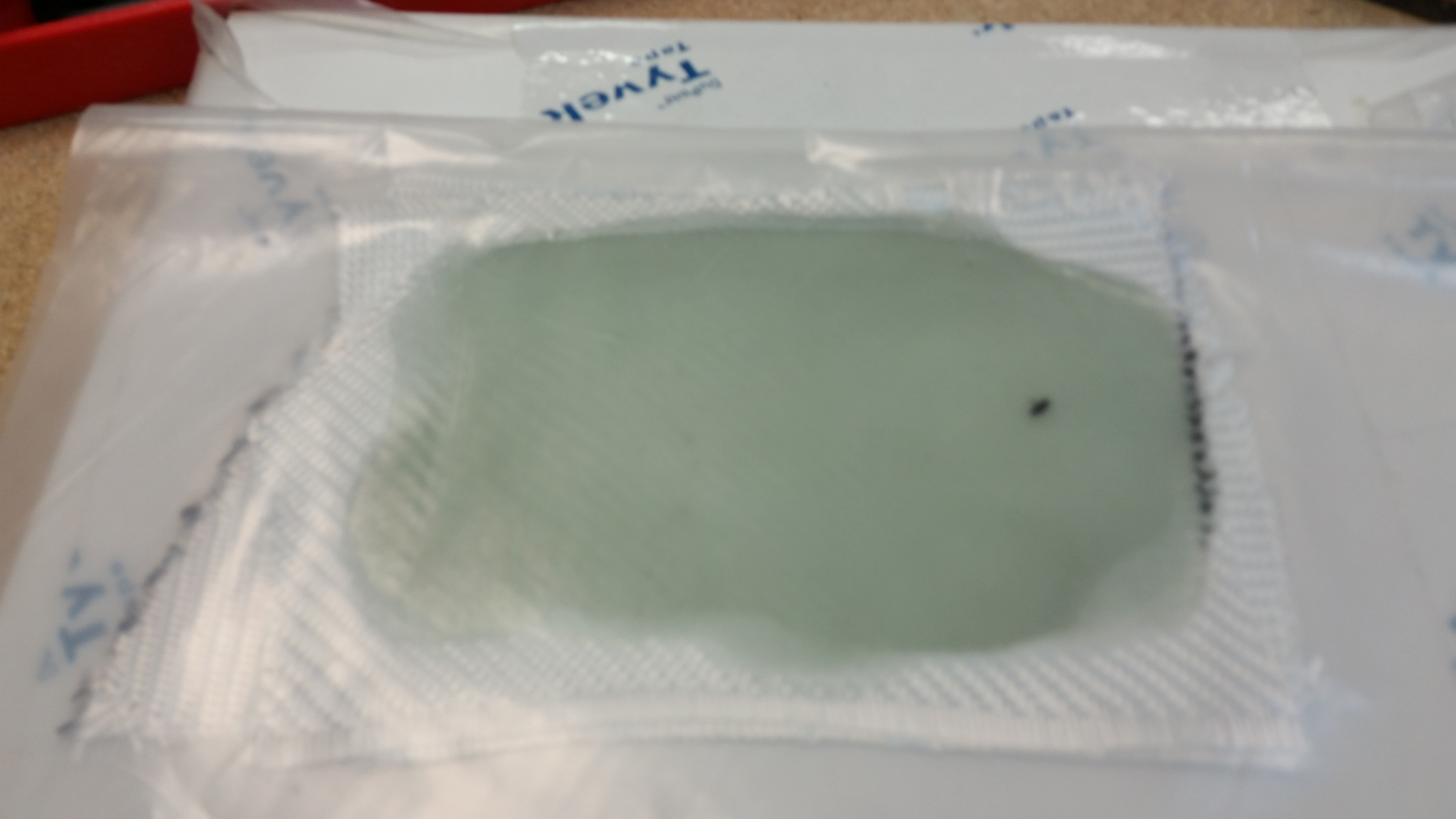
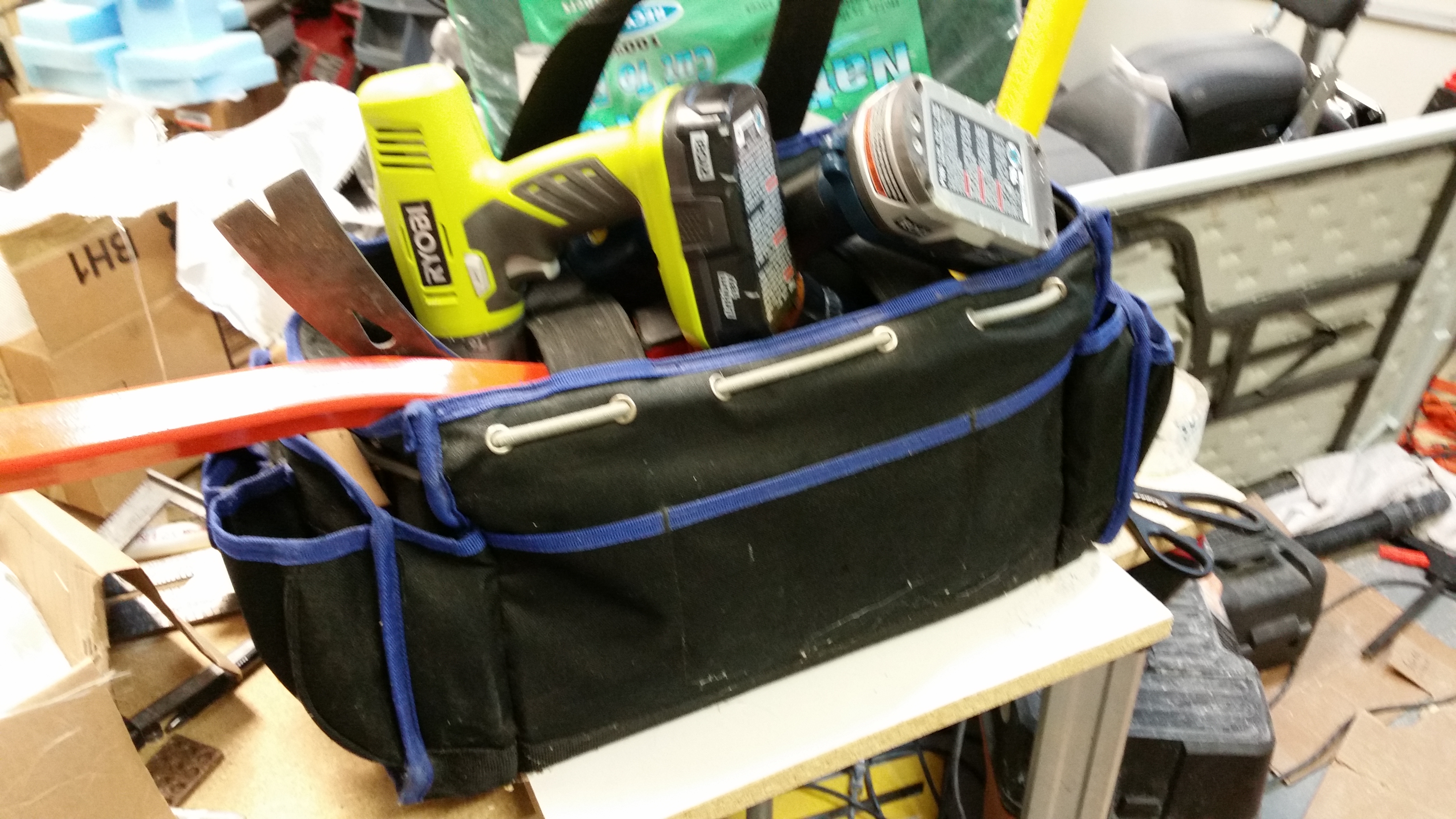
Since I had a little bit of pure epoxy left over, I grabbed the BID scrap box and a piece of plastic to make a 4-ply BID sheet, of which I would cut out a Vortilon or two.  I laid the 4 plies of BID into a pre-preg setup and poured all the epoxy into the layup.  After heating up the pre-preg with the heat gun it flowed well enough to wet out all the epoxy.  I then put another plate on top of it and weighed it down with my heavy tool bag (pic below).

Vortilon 4-BID layupWeighing down Vortilon 4-BID layup

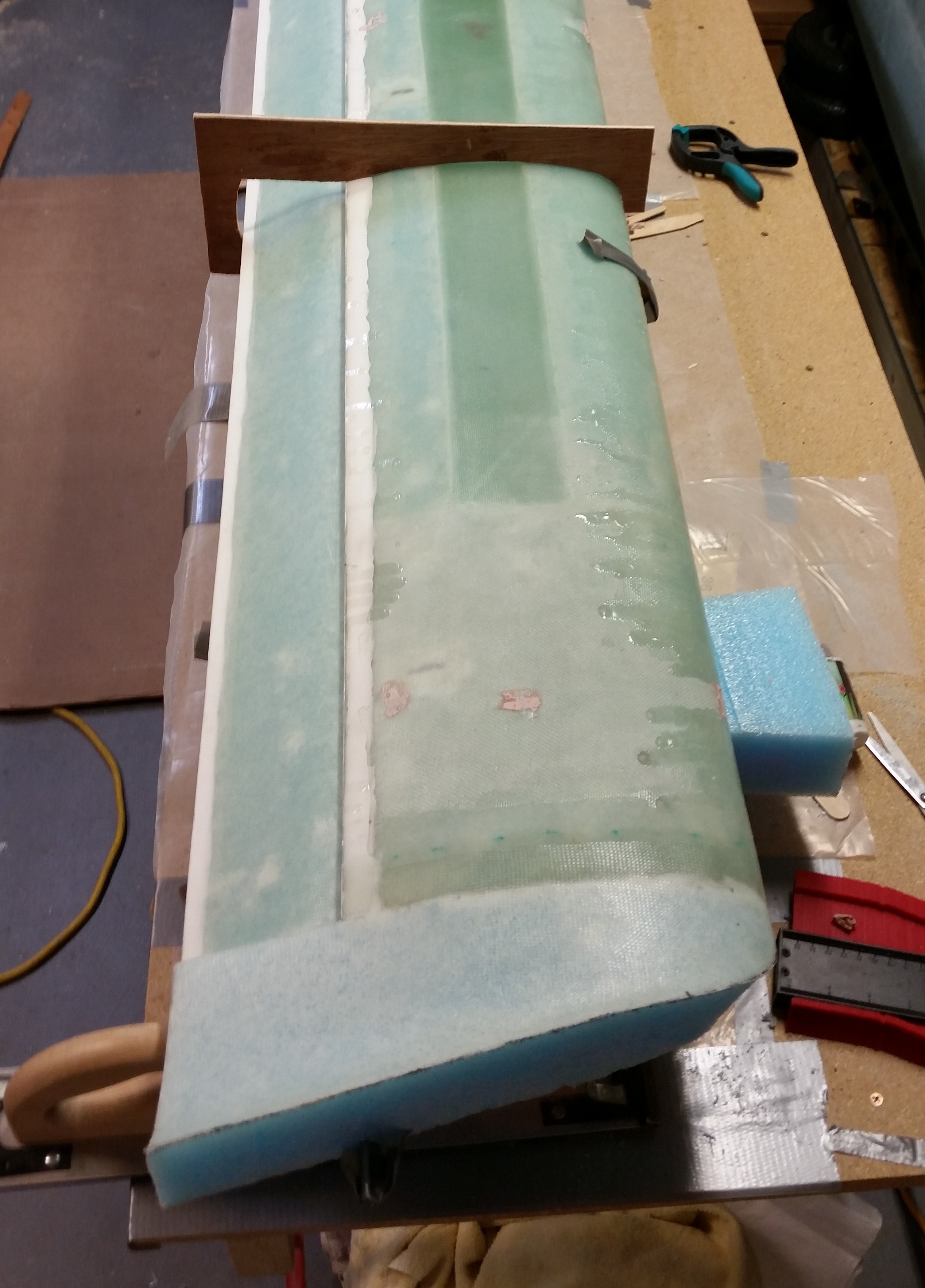
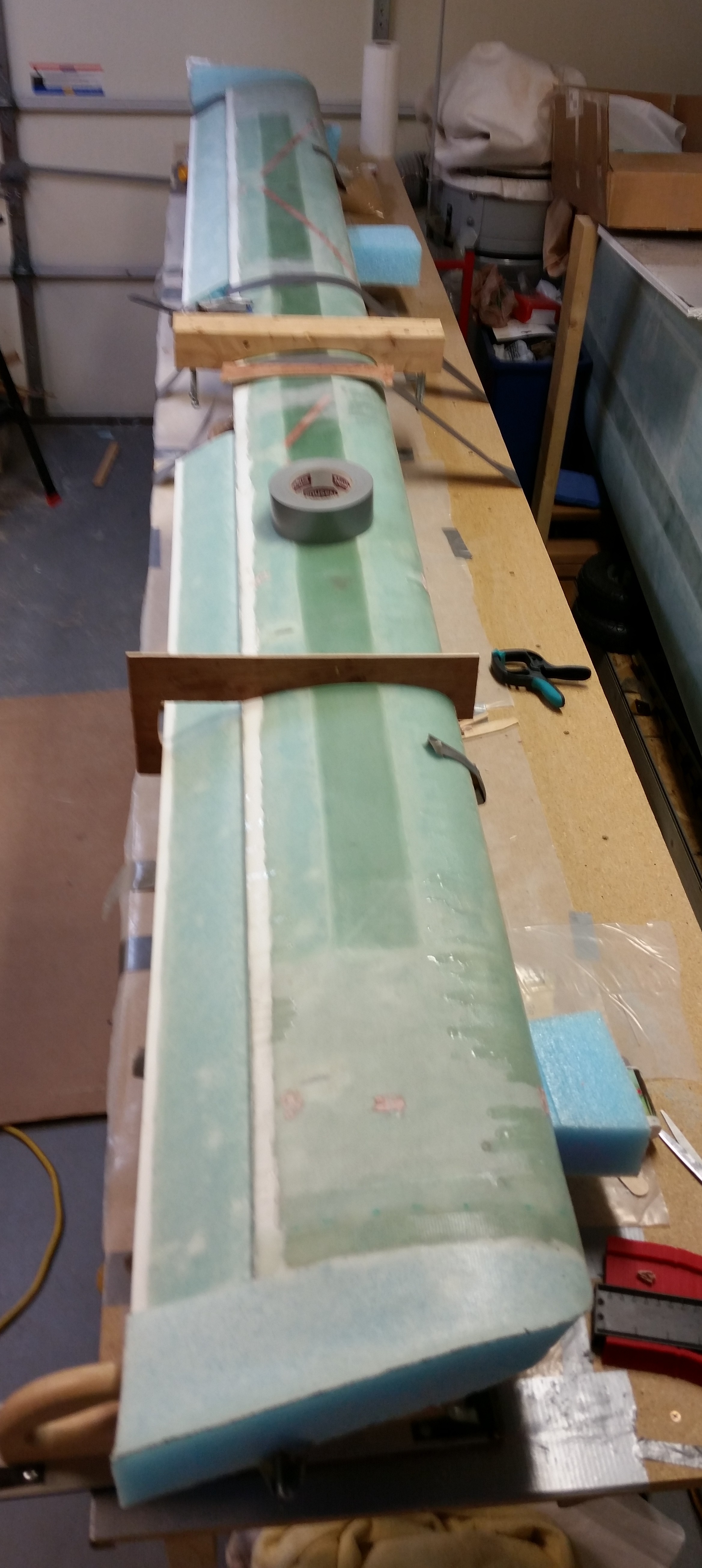
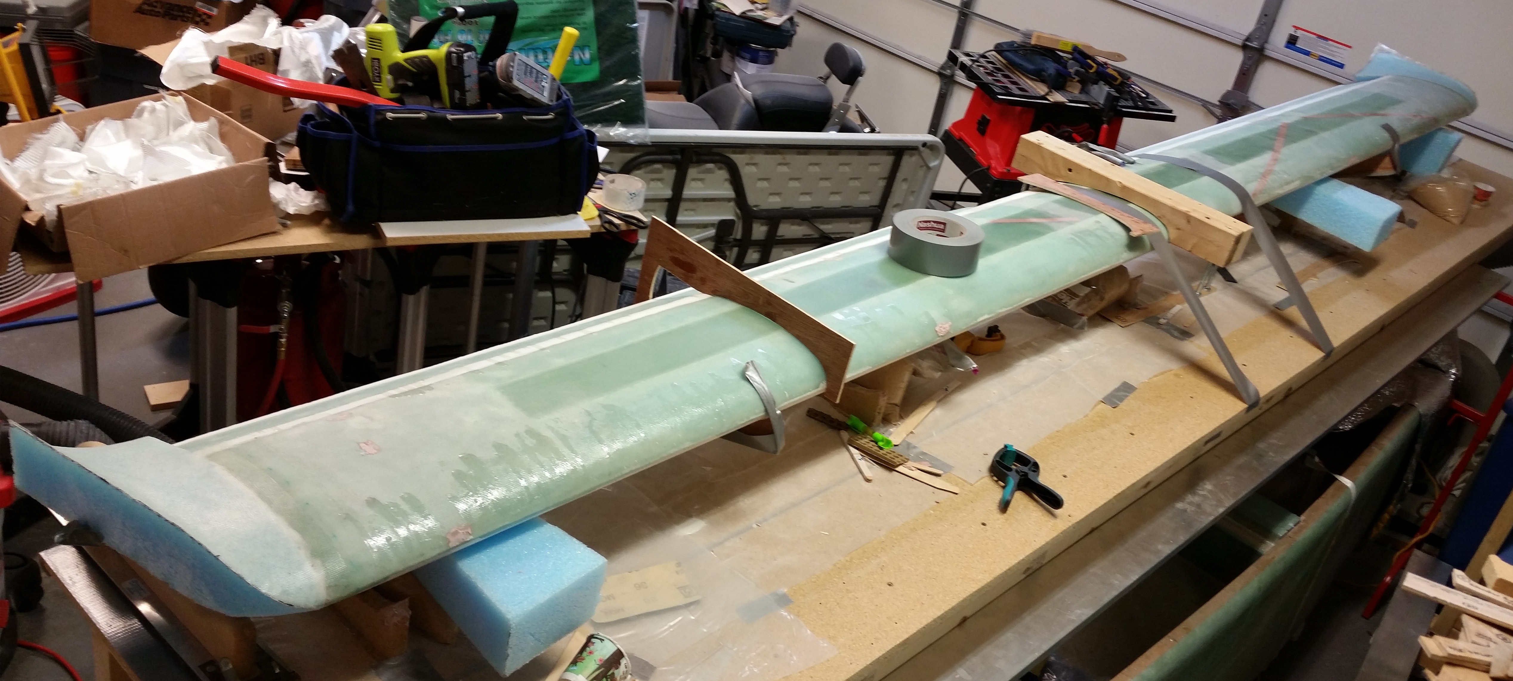
Here’s a few shots of the finished top side of the right swoosh tip.

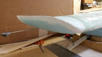
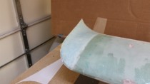
Trimmed Right Swoosh Tip

Glassed Swoosh Tips

Glassed Swoosh Tips

Next will be the shaping and glassing of the bottom sides of the canard swoosh tips.  Then back to working on the elevators to get the weights mounted, etc.