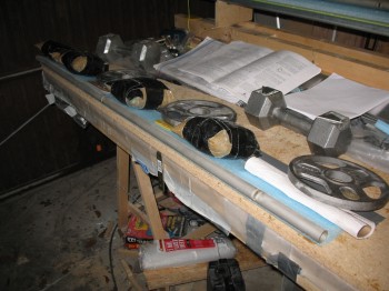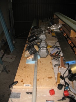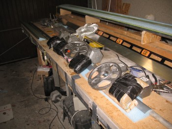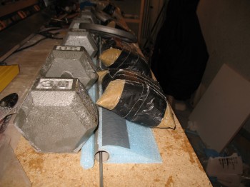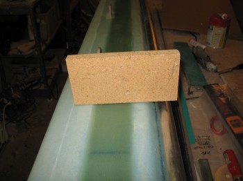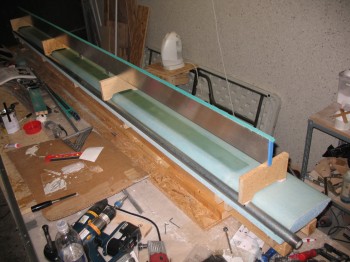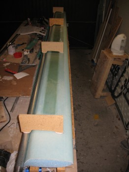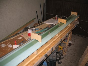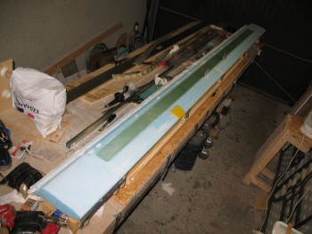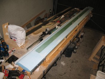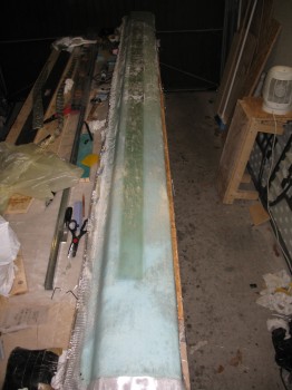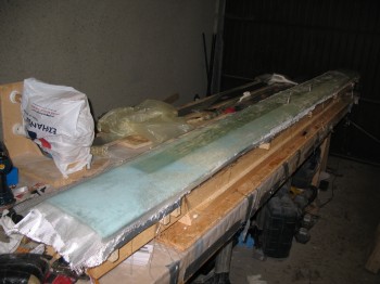
Chapter 10 – Upper canard spar cap

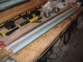
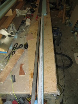
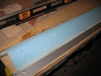
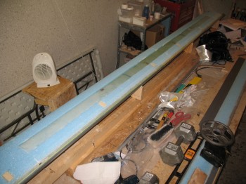
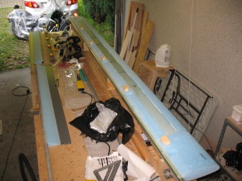
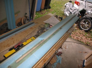
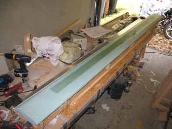
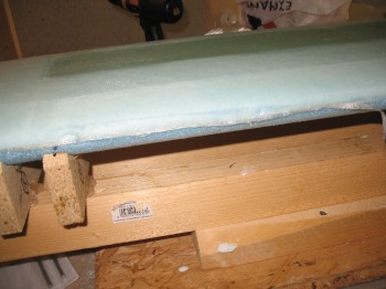
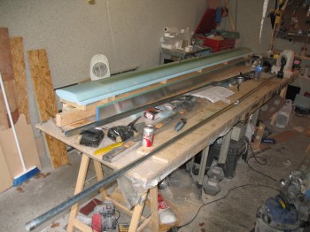
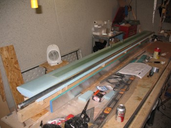
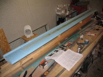
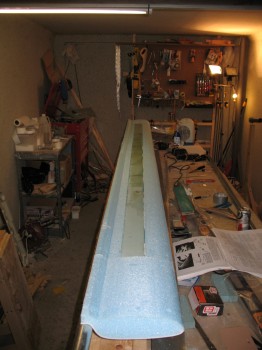
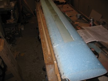
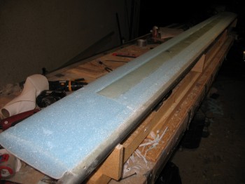
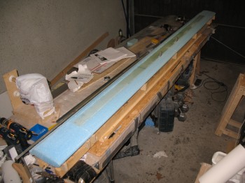
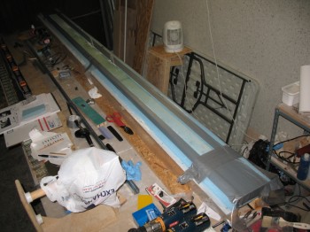
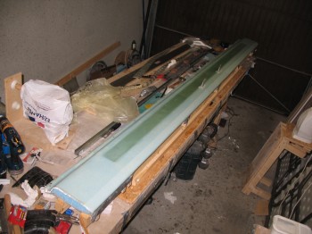
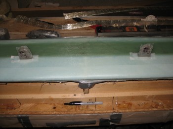
Today I spent a lot of time ensuring the canard was straight and level.  I used strings, I used the aluminum straight ‘board’, I used the contour checker, I used the 6 ft carpenter’s level and I used a laser level kit.  I checked, leveled, shimmed, re-checked, re-leveled and re-shimmed countless times.  Obviously this is my final time for ensuring the canard is straight, twist-free & level before the spar cap and especially the top skin is glassed (this warning is explicitly spelled out in the plans as well).

There was a very slight twist to the canard which I remedied through shimming.  One thing that kept perplexing me, until I finally cracked the code was that the top middle of the canard dipped down a bit, but then the bottom of the canard was slightly crowned.  I realized after finally working the problem with both sides together, that my canard was slightly hourglass shaped.  Well, at least it was symmetrical!  I took a long look at it, and concluded that a good amount of the narrowest part of the hourglass shape will be stuffed away in the middle of the fuselage.  Apparently this was the shape as it came out of the hotwire cutting process.  There would be some narrowing (thickness, not width) towards the Inboard canard area to contend with, but it wasn’t extreme enough to start over or panic.  It looked like there will just be less micro filler towards the Outboard canard ends and just a tad thicker micro fill towards the Inboard areas.

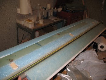
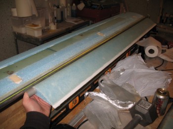
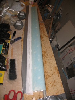
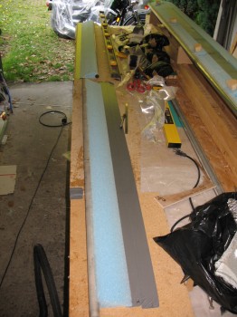
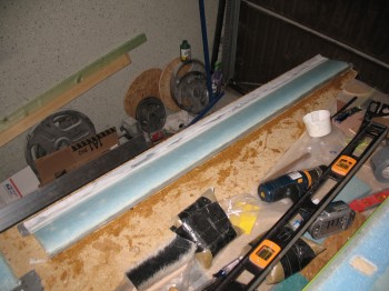
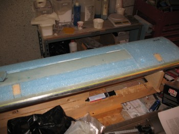
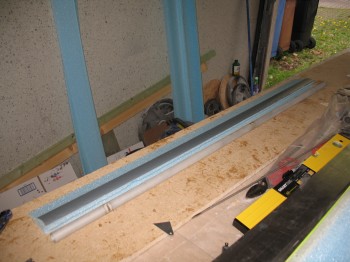
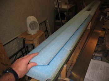
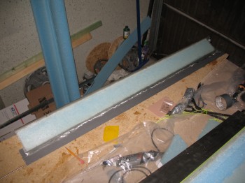
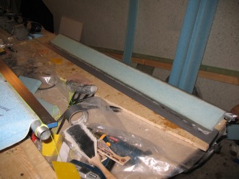
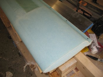
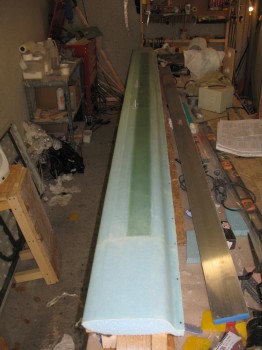
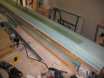
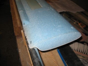
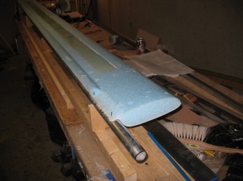
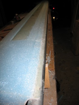
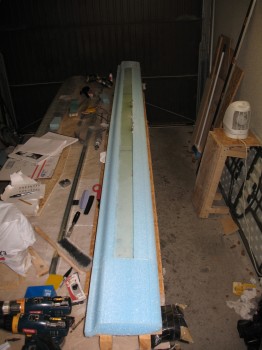
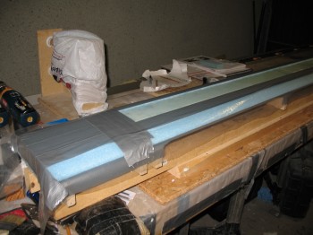
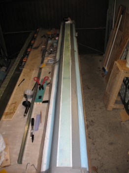
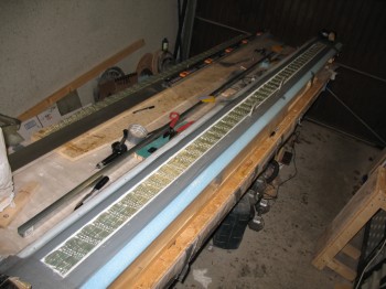
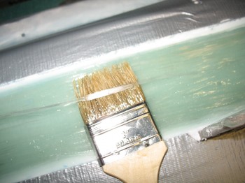
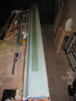
I moved on to getting the spar cap layup knocked out.  I sanded the shear web/spar cap trough.  I did also sanded down and shaved a little off the Outboard 11″ canard tips to match the rest of the canard shape.   I taped the edge & added plastic around the entire perimeter of the spar cap trough.

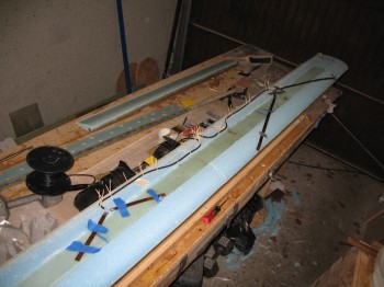
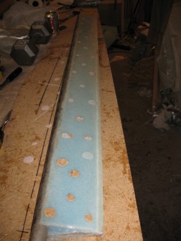
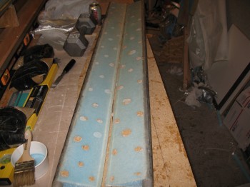
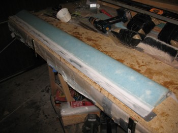
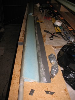
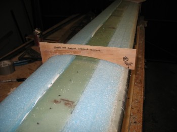
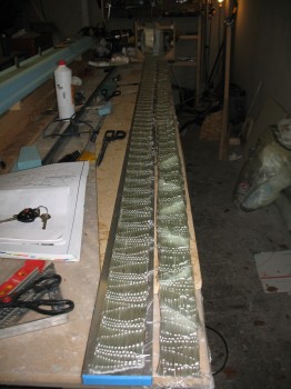
I micro’d the edges of the spar cap trough.  I cut & laid up the 3″ UNI tape, and ended up using 9 pieces in the following order:  108″, 92″, 103″, 70″, 81″, 50″, 60″, 30″, 18″.  I then peel plied the entire spar cap layup.
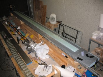
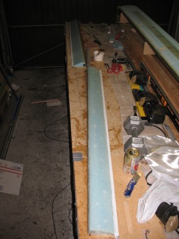
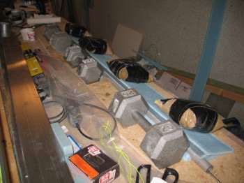
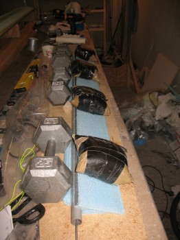
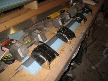
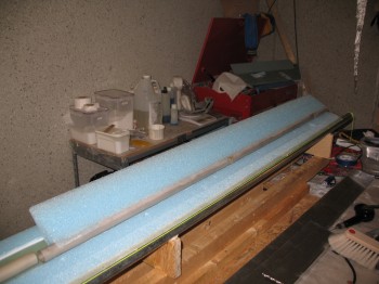
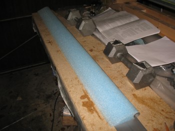
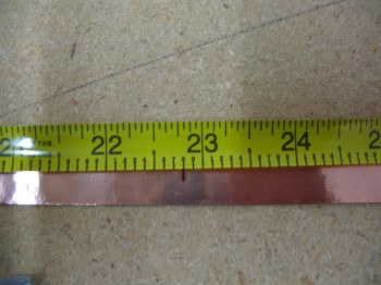
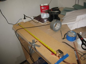
Chap 10 - Upper canard spar capAbout an hour after I finished, I removed the tape & plastic from around the newly glassed spar cap.
Chapter 10 – Canard Antennas

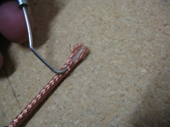
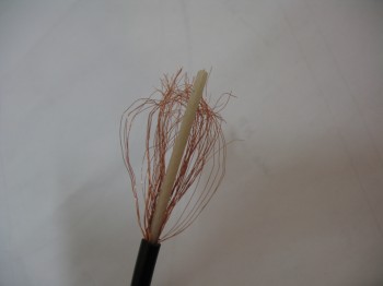
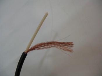
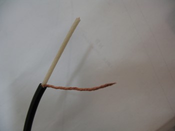
Today I made the 2 canard antennas that will be mounted under the top skin.  I’m using the antenna kit from RST Engineering and following the guidance & instructions of Jim Weir.

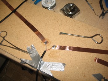
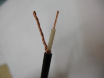
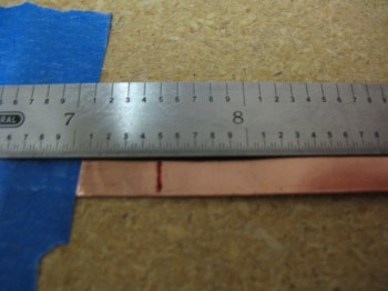
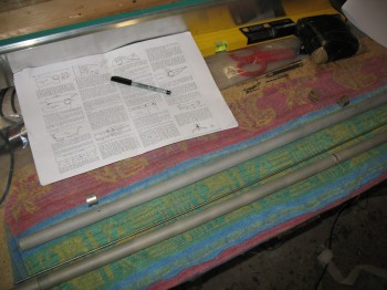
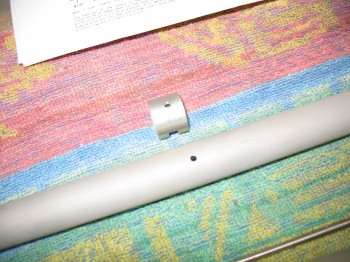
I made the VOR antenna first, with each leg (or “ear”) of the dipole measuring 22.8 inches in length.  I’m also using 50 Ohm RG-58 stranded antenna cable.

Chap 10 - VOR AntennaChap 10 - VOR AntennaChap 10 - VOR AntennaChap 10 - VOR Antenna

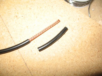
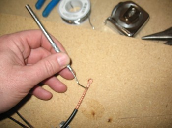
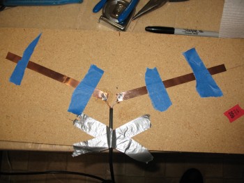
The following pictures show the general steps I take to make an antenna using Jim Weir’s design.  I will say that going back and reviewing the instructions on how to make these antennas, I should have probably cut the leads a little shorter that attach to the copper foil. Of course I think the antennas will still work fine, they’re probably just not as optimized as they should be for Tx & Rx.

Making Long-EZ AntennasMaking Long-EZ AntennasMaking Long-EZ AntennasMaking Long-EZ AntennasMaking Long-EZ AntennasMaking Long-EZ AntennasIMG_0113I made the ILS antenna next, with dipole legs measuring 7.5 inches.

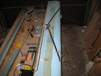
Chap 10 - ILS antennaChap 10 - Canard ILS antennaI then mocked it up on the canard as well to figure out the best placement for both the VOR & ILS antennas.

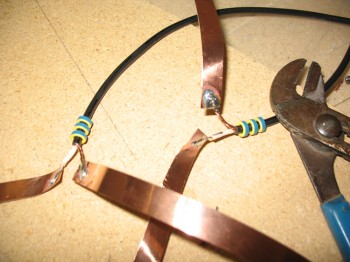
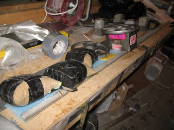
Chap 10 - Canard VOR & ILS antennasThe picture below shows the 3 Ferrite Toroids that are placed on the RG-58 Antenna cable close to the dipoles on about a 1/4″ spacing.  The ferrite toroids strip off any reflected power from the antenna (technically the outside of the coax braid) before it can get into the electrical system.  Using 3 ferrites eliminates about 99.9% of the reflected signal.

Chap 10 - Canard AntennasThese 2 antennas make up the last of the copper foil antennas that will get embedded into the skin of the flying surfaces.  Here is a summary of all my copper foil antennas:

COM1 – Left Upper Winglet
COM2 – Right Upper Winglet
VOR1 – Left Wing
VOR2 – Canard
ILS – Canard
FM Radio – Right Wing


Chapter 11 – Elevators & more

I was busy working move stuff much of the day, so I left the elevators bondo’d to the table to cure even more.

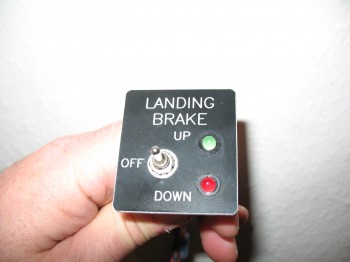
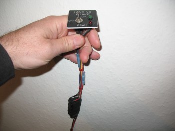
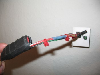
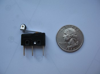
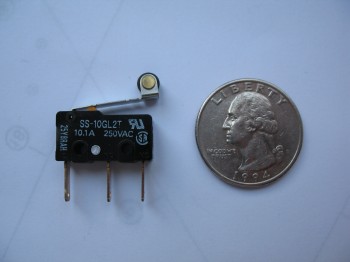
My buddy Marco asked me to take some pics of my Landing Brake Switch that came with the landing brake setup I got from Jack Wilhelmson at eznoselift.com.

I took a pic of the switch & its wiring, and the microswitch that is used in the system as well.

Section VI - Landing BrakeSection VI - Landing BrakeSection VI - Landing BrakeSection VI - Landing BrakeSection VI - Landing Brake

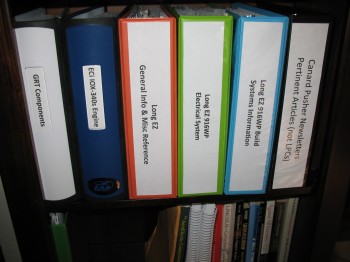
And since we had been discussing the process of researching Long-EZ construction, I shared a picture of my project documentation binders & research.

My Long-EZ Docs & Reference Material


Chapter 11 – Elevators Glassed

Early this morning I razor cut the edges of both the Left & Right elevators.  I used my long carpenter’s level and it work well.

I left the Right elevator bondo’d to the table to ensure it cures thoroughly & straight.

I then removed the Left elevator from the workbench.  Unfortunately, some micro had seeped under the Inboard edge and tore out a chunk of the elevator foam, which remained securely fastened to the workbench.  I carefully removed the chunk of foam from the table, then set it aside with the elevator.  I then removed all the remaining blobs of 5-min glue & small bits of foam (that typically come off of a foam surface when it’s 5-min glued down) to finish prepping for the Left-side elevator’s final layup.

I sanded the Left elevator LE & used the Dremel tool to remove ~0.4″ of foam & dead micro from the TE.

I then bondo’d the Left elevator down to the workbench right-side up.

I then cleaned up & micro’d the extracted piece back into place.

I then glassed the top side of the Left elevator, peel plied the LE, and then dry micro’d & peel plied the TE.

Chap 11 - Left Elevator GlassedChap 11 - Left Elevator Glassed

I trimmed the overhanging glass back within 1/4 inch.

After the Left elevator’s last layup was in the books, I went to my downstairs shop & cut 4 pieces of BID 13.5″ wide at 45° for the Canard top skin.


Chapter 11 – Glass Elevators

The Right elevator seemed to be curing a little bit slower than normal, so I had thrown a heater on it and that seemed to do the trick.  I pried it off the table, hit the front round edge of the glass with a hard sanding block to prep a transition for the topside glass layup that would overlap onto the bottom glass for glass-to-glass continuity.

Chap 10 - Right elevator after glass edge sanded

I then removed about 0.4 inches of TE foam & sanded down the newly visible glass for glass-to-glass continuity at the TE as well.  I then bondo’d the Right elevator right-side up to the workbench.

Chap 11 - Right elevator bondo'd to table

Chap 11 - Right elevator TE sanded/prepped

With both elevators now affixed to the workbench, I proceeded to layup the top side of the Right elevator & the bottom of the Left elevator.

Chap 11 - Elevators R/top & L/bottom prepped Chap 11 - Right elevator top glassedChap 11 - Right elevator glassedChap 11 - Left elevator bottom glassed

I peel plied the LE of the Right elevator, and after the epoxy had cured a bit & the glass was still tacky, I micro’d in the channel on the TE of the Right elevator & covered it with peel ply.

Just before I glassed the elevators, I had finished cutting all the H100 6# high density foam inserts and their respective positions in the canard (L&R of CL: 9.7″, 34.1″ & 59″).

Chap 10 - High Density Foam Inserts

Chap 10 - High Density Foam Inserts (+ Ch 11)

I micro’d in the high density foam pieces into place.

Chap 10 - Canard foam inserts micro'd in


Chapter 10 – High Density Foam Hard Points

I spent an hour or so researching and planning the torque offsets configuration & hinge placement.

Chap 10 - High Density Foam Block Inserts

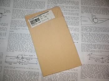
I rounded up my block of 6# high density foam.

Chap 10 - H100 6# High Density PVC Foam

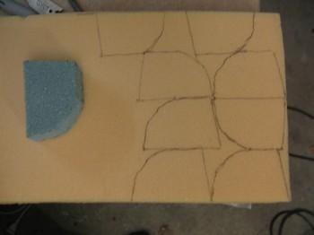
I “designed” my insert with a scrap of blue foam and once I had it locked in & test fitted into the canard, I used it as a template for the high density foam inserts.

Chap 10 - High Density Foam Block InsertsI test fitted 2 of the inserts and they fit well, but I didn’t micro them in place yet.  This foam is tough stuff!

Chap 10 - High Density Foam Block Inserts

I turned my focus back onto the elevators and 5-min glued the Left elevator upside down to the workbench for glassing.

Chap 11 - Bonding elevator to workbench for glassing

I then cut 3 sets of elevator glass: 1 set for the Left elevator bottom side, and 2 sets for the top sides of the elevators.


Chapter 11 – Elevators

Today I started building the elevators.  Not because I simply got bored with the canard, but there are foam hard mounts that get inserted into the blue canard foam near the trailing edge before it gets glassed.  These foam hard points hold the elevator hinge brackets (with a little help from a lot of flox) into the underside of the canard, allowing the elevator torque tubes to pivot around the hinge brackets . . . which are spaced at various points along the canard, matching up of course to the hinge insert slots that I riveted into the elevator torque tubes.

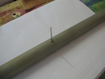
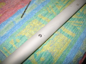
I started off the elevator build by assembling the elevator torque tubes.  I inserted the elevator torque tube hinge inserts (NC-2) into the elevator torque tubes, drilled the holes, chamfered the holes, and then riveted the hinge inserts into the torque tubes.

Chap 11 - Elevator torque tube assembly

[NOTE:  I’m using the Cozy Girrrl’s Torque Tube Offsets, which were developed for the Cozy… pretty much a wide-bodied LEZ.  These offsets allow the side hole in the fuselage walls to be made with a much tighter tolerance (read: smaller) and therefore less undesirable air (read: cold!) makes it through the elevator fuselage slots/holes.  The result of all this is that I only require 4 each hinge inserts (NC-2) vs the 5 required for a stock Long-EZ build.]

Chap 11 - Elevator torque tube assemblyChap 11 - Elevator torque tube assemblyChap 11 - Elevator torque tube assembly

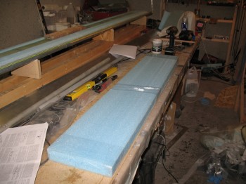
I then pulled out the foam elevator cores.  The actual elevator cores didn’t come out quite so easily, so there was a lot of razor cutting (and admittedly cussing…) and a fair amount of work to extricate the cores from the foam block.

Chap 11 - Elevator foam prep

I cleaned up the foam elevator cores & test fitted the elevator torque tubes into the round opening at the front of the foam cores.

I then installed the triangular hinge jigs (NC-7) into the hinge inserts & held them in place with the stainless steel hinge pins.  I started with the Right torque tube & inserted it into the Right elevator core with micro to secure it in place.  Since I only had 2 hinge jigs (NC-7), I let the Right elevator assembly cure before moving onto the Left torque tube (in pictures #2-4 of the Left torque tube below it appears that the foam elevator core is attached to the torque tube, but they were only mocked up before I actually micro’d them together AFTER the Right elevator torque tube and foam core were bonded together).

Chap 11 - Attaching elevator foam to torque tube

Chap 11 - Attaching elevator foam to torque tubeChap 11 - Elevator foam/torque tube attachedChap 11 - Elevator foam/torque tube attached

Chap 11 - Attaching elevator foam/torque tubeChap 11 - Attaching elevator foam/torque tubeChap 11 - Attaching elevator foam/torque tube

As the Left elevator core was curing to the torque tube, I went to my downstairs shop and cut the 2-plies of UNI at ± 30° for the Right elevator.

Chap 11 - Elevator foam/torque tube attached

I attached the Right torque tube/foam elevator assembly bottom side up to the work bench using 5-min glue, while the Left elevator torque tube/foam core assembly micro bond was curing.

Chap 11 - Elevator foam/torque tube attachedChap 11 - Elevator prep for glassChap 11 - Elevator prep for glassChap 11 - Elevator prep for glass

Chap 11 - Left elevator prepped for glass

I then microslurried the foam on the Right elevator bottom-side and glassed the 2-ply UNI layup, alternating the orientation by 30° for the 2 plies.

Chap 11 - Right elevator 1st side glassedChap 11 - Right elevator 1st side glassed


Chapter 10 – Top Spar Cap Prep

I checked the canard to ensure everything was good with the layup from yesterday.  All was good except for the LE foam damage.

Chap 10 - Canard top spar capChap 10 - Canard top spar cap I pulled the 2″ peel ply off the front LE & around the mounting tabs and took a few minutes to clean up the peel ply boogers.

Chap 10 - Canard top spar cap Chap 10 - Canard top spar cap I then “Fein” sawed/razor cut each of the canard ends so the glass was flush with the foam.  I also clamped a straightedge onto the trailing edge (TE) and cut it as well.

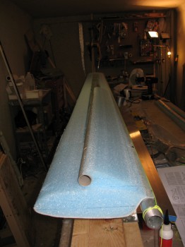
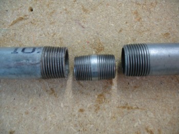
Chap 10 - Canard top spar capChap 10 - Canard top spar cap I had looked high & low for weeks to find a 130″ long pipe that would work as the TE alignment pipe.  I even borrowed a pipe from the Civil Engineers on base, but it wasn’t straight when I checked it out at the house. So I went to Praktiker & bought a 2000 mm (~78-3/4″) and 1500 mm (~59″) 1″ water pipe.  I used a 3/4″ threaded connector to help keep the 2 pipe pieces together & straight.  I cleaned the pipes with acetone & then Simple Green and then mounted them together.

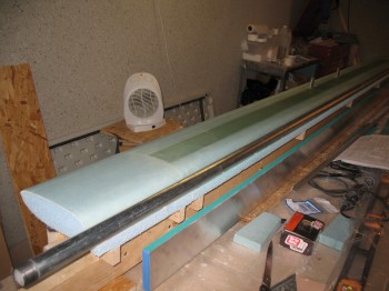
Chap 10 - Making the long pipe I then bondo’d the whole assembly to the TE lip of the canard, using my aluminum straight “board” to make sure it was all straight.

Chap 10 - Canard...long pipe attachChap 10 - Canard...long pipe attachChap 10 - Canard...long pipe attachI trial fit, and then cut crescents in the wood support boards, that would hold up the canard when it was flipped over right side up.

Chap 10 - Making new support baseAfter I got the 4 support boards prepped, I bondo’d them to the bottom canard surface on one side and the metal pipe on the other.

Chap 10 - Making new support base Chap 10 - Making new support base Chap 10 - Making new support base I then flipped the canard right side up & secured the end wood supports to the original wood canard jig base.

Chap 10 - Resting on new baseChap 10 - New base & canard secured I cut off the fishtail at the topside TE.

Chap 10 - Removing Canard FishtailChap 10 - Removing Canard Fishtail Chap 10 - Removing Canard Fishtail Once I got the fishtail foam removed, I then removed all the tacks and peel ply from the TE.

Chap 10 - TE peel ply removedChap 10 - TE peel ply removedI used the top contour checking template to finish sanding the remaining foam off the TE area left by removing the fishtail.

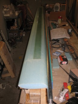
Chap 10 - Checking canard top contour Before the final mounting of the canard to the original base, I took it out of the garage and flipped it around end-to-end so that I could work on the LE with it at the front edge of the table, facing both the lighting and closest to the epoxy table. Then I spent about 2-1/2 hours using straight edges, string, and a laser level kit to get the canard as perfectly aligned as possible.  I had about a 0.15 inch drop at each end, so I shimmied the each end support strut with a couple of stirring sticks, which seemed to do the trick.


Chapter 10 – Bottom Spar Cap & Skin

I checked the Roncz Canard 11″ tips that were micro’d on yesterday.  Everything cured well so I pulled the nails that were holding the foam pieces together.  When I leveled out the canard, I could see where the 11″ canard tips were slightly off from the rest of the canard. So I took my time and very carefully sanded the canard tip bottom surfaces to match the rest of the canard.  I did this for both the Left & Right side.

I then precut the 7 each 3″ UNI tape lengths: 108″, 108″, 98″, 90″, 80″, 60″ and 12″.  Since the Roncz Canard plans state to simply layup the number of lengths that will appropriately fill in the spar cap trough, I can make modifications to my UNI tape lengths if and when they may be required.  I wanted to have as much of the prep work completed, since I will take Burt’s advice in the Roncz Canard plans and layup the 3″ UNI tape spar cap glass and then roll right into glassing the lower skin of the canard.

Chap 10 - Canard bottom spar cap

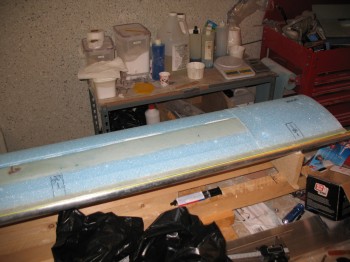
I carefully sanded the LE edge to knock off any excess foam from the hotknife cutting process, then vacuumed the entire canard and taped half-way up the LE.

Chap 10 - Canard bottom spar capChap 10 - Canard bottom spar cap

I tacked on a 1″ strip of peel ply down the entire TE, but with only 1/2″ on the TE and the other 1/2″ hanging overboard.  Once I finished with the peel ply, I taped around the spar cap & used plastic to protect the canard foam surface.

Chap 10 - Canard bottom spar capChap 10 - Canard bottom spar cap

I bagged (like a wedding cake frosting bag) thick micro around the edge of the spar cap.  I then laid up the spar cap using the contour template regularly to check the amount of glass in the trough.
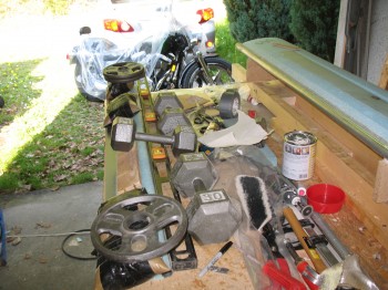
Chap 10 - Canard bottom spar capChap 10 - Canard bottom spar capI was using a whole new batch of 3″ UNI tape that I ordered just before I left Tampa, and I have to tell you I didn’t like the new stuff at all.  There must be a new supplier to ACS because the roving threads continuously broke while trying to remove them from the glass weave, and I even found a piece of scotch tape holding the glass weave together (thankfully only once), which of course I cut out.

Chap 10 - Canard bottom spar capOnce I was finished laying up the spar cap, I took a very short break, then carefully removed the protective tape and plastic from around the edge of the spar cap trough.  I then used micro paste to fill in the joints & dings, and then microslurried the remaining canard bottom blue foam surfaces.

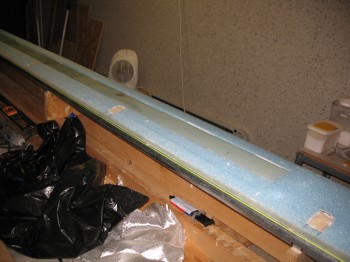
Chap 10 - Canard bottom skinChap 10 - Canard bottom skinI then laid up the bottom canard skin which was fairly straight forward:  1 long layer of UNI, 1 long layer of BID (4 pcs total & only overlapping in the center, not on the Outboard flight surfaces), then 1 long layer of UNI again, for 3 total layers.  The UNI is somewhat of a pain to work with at times, since it’s cut with the strands of glass, so the glass continuously wants to peel off the sides of your layup.  Dale Martin recommended that I do like many builders & cut the UNI here just a tad wider and then masking tape the edges to keep it from unraveling.  I was too lazy & cheap to do that, so I just powered through.
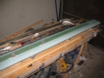
Chap 10 - Canard bottom skinChap 10 - Canard bottom skin

Once I glassed the lower skin layups, I knife trimmed the edges to 1/4″ and peel plied the LE with 2″ wide peel ply tape.  I also peel plied around the canard mounting tabs.

Chap 10 - Canard bottom glassingChap 10 - Canard bottom glassingChap 10 - Canard bottom glassingChap 10 - Canard bottom glassing

After a few hours had passed, I used a razor knife to cut the glass along the middle of the LE adjacent to the line of duct tape underneath.  While I was pulling away the duct tape, dead glass and peel ply, I had about a 10″ section of LE foam that simply decided it wanted out and peeled off with the tape.  I will have to fix that area before glassing the top of the canard.

With that, I double checked the layup and then let it cure.  One thing I did notice is that in a couple of areas the spar cap is a hair thicker than it should be.  So there’s about a 0.05″ ridge along the spar cap edge under the skin.  The bond looks good, there is just that small ridge that I will have to contend with when finishing the canard.