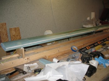
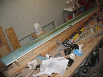
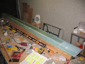
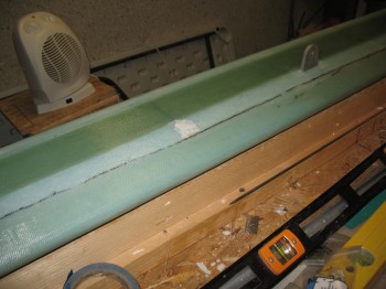
Chapter 13 – NG30 high density foam plates

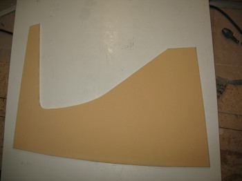
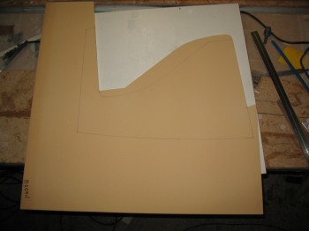
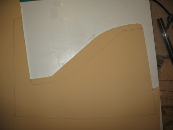
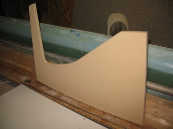
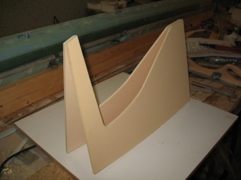
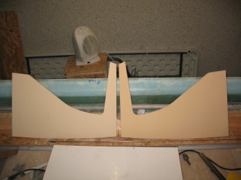
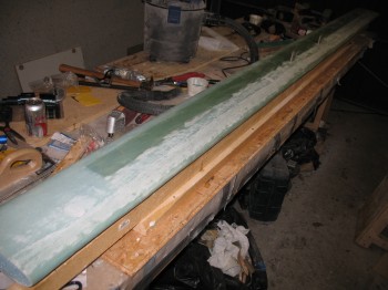
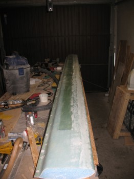
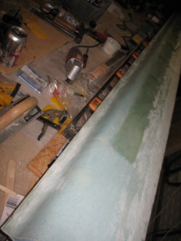
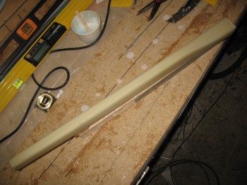
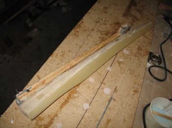
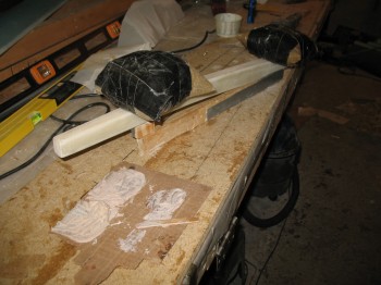
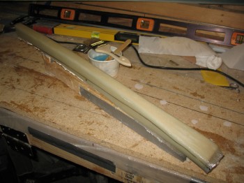
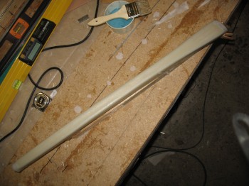
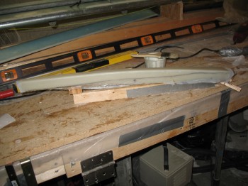
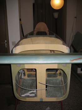
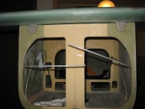
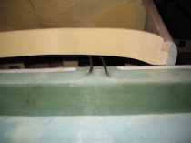
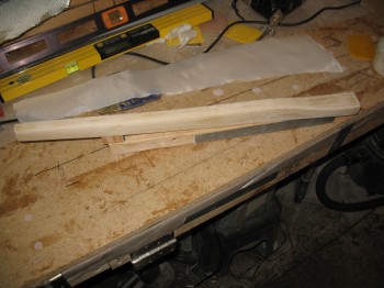
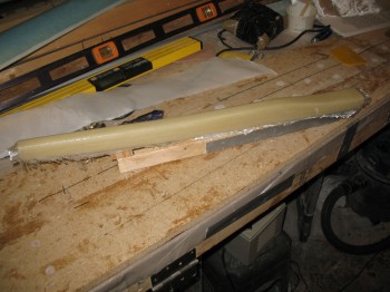
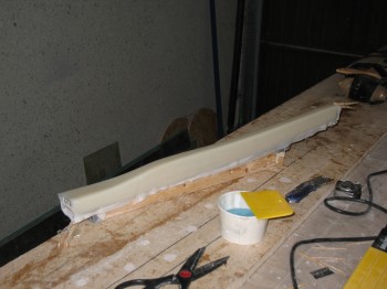
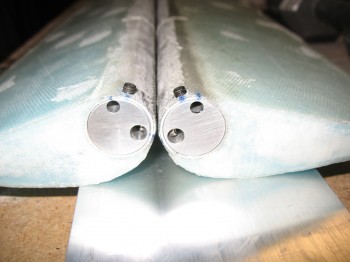
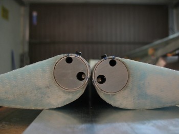
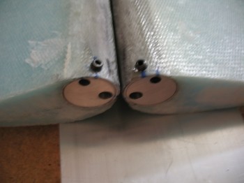
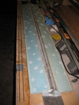
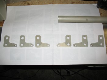
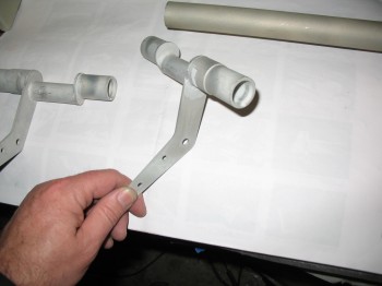
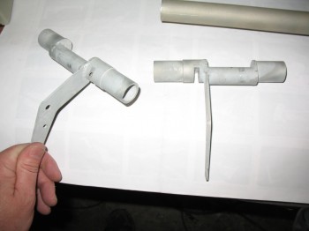
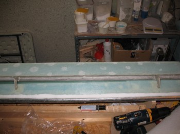
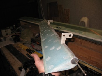
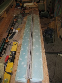
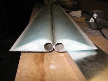
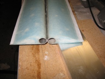
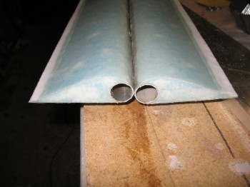
Today I cut out the NG30 high density foam plates that make up each side of the channel that the nose gear electric actuator will sit in.  Not only do these plates start out with some of the densest foam out there (the H250 has a 16# density), but it gets covered with a 4-ply BID layup on each side of just ONE plate, so that’s 16 plies between the 2 plates.  Also, in talking to Jack Wilhelmson about installing his landing gear actuator, I added 1 ply of reinforcement BID along the top curved portion of each NG30 as he recommended just to add a little robustness & strength [Note:  Like many other components I’m building on this Long-EZ these NG30s are not to built to stock specs as spelled out in the plans but rather they follow the Davenport extended nose design, which obviously look different than stock plans NG30s].

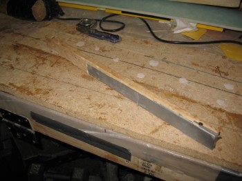
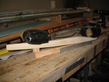
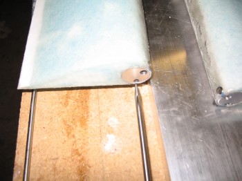
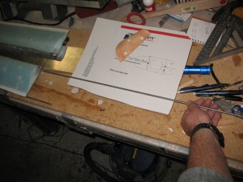
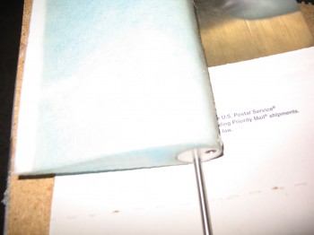
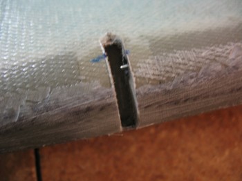
Chap 13 - H250 foam NG-30 sideChap 13 - H250 foam NG-30 sideChap 13 - H250 foam NG-30 sideChap 13 - H250 foam NG-30 sideChap 13 - H250 foam NG-30 sidesI trimmed down the sides & sanded them even so that the NG30s closely matched each other.

Chap 13 - H250 foam NG-30 sidesChap 13 - H250 foam NG-30 sides


Chapter 13 – Initial Nose Plans

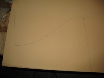
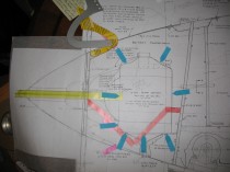
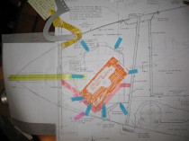
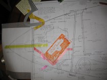
Well, today I decided to act on yesterday’s vow to figure out my build plan for the Davenport extended nose.  I broke out the Davenport extended nose plans, figured out a myriad of details and made a template for my NG-30s.

One thing in specific I was looking at was the battery position & its installation configuration in relation to the heated pitot tube, and how it effected the capability of retracting the pitot tube.

Now, let me backtrack to February 2013.  I may have been a little remiss in the reporting of my project progress since I overlooked an extremely important component: my retractable heated pitot tube made for me by good friend Marco, a fellow Canardian and Long-EZ builder . . .

My Retractable Heated Pitot Tube

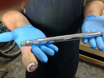
Yes, Marco–being the excellent & talented machinist that he is–machined me this beautiful retractable heated pitot tube.  Of course this wasn’t just a simple ‘throw some metal on the lathe and here it is’ endeavor, it took literally a couple months of research and discussion, and quite a bit of engineering and design.  And countless hours of machining work by Marco.  Marco describes the first part of the process here on his Blog What have I gotten myself into!

In addition, Marco covers the features of my Pitot Tube in this awesome video he made:


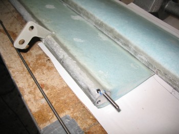
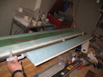
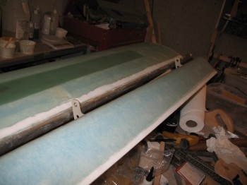
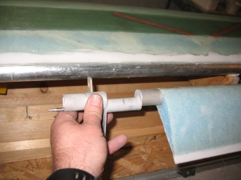
Chapter 13 – Planning over coffee

Today I had to do a bunch of running around getting ready to move.  I did stop by a local Starbucks to finish some planning and get an Aircraft Spruce order together.  One thing I was trying to figure out before I finalized the order is if I would need more 1/4″ H250 High Density foam for the nose build.

I determined I most likely wouldn’t and submitted the order, but made it a priority to finish getting THE plan finished for my nose.


Chapter 22 – Transponder Antenna

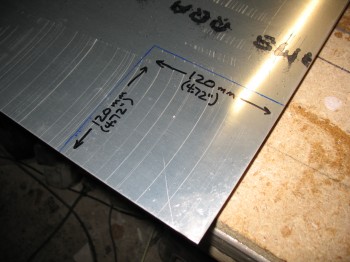
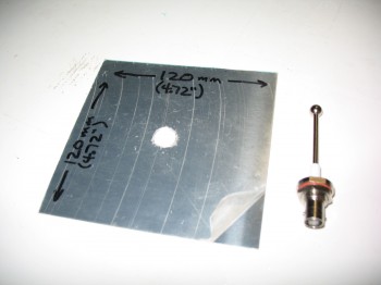
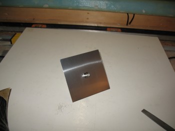
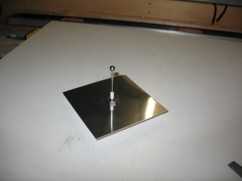
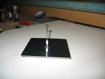
Today I built my transponder antenna.  I had already collected some data . . . read Jim Weir’s stuff, and then ran across some transponder antenna info from Dynon.  After a little bit more research, I decided to follow Dynon’s recommendation to go with a square 120mm x 120mm (4.72″ x 4.72″) metal plate for my transponder antenna.  This allows for a wider range of frequencies vs a round plate.  Also, this size plate is optimized for transponder frequencies.  I used aluminum of course for weight, 0.025″ thick.

Chap 23 - Transponder Antenna

I cut out the plate & then drilled a 1/2″ hole in the middle of the plate, chamfered the hole & then installed the TED transponder antenna.

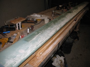
Chap 23 - Transponder AntennaChap 23 - Transponder AntennaChap 23 - Transponder AntennaChap 23 - Transponder AntennaI then focused my attention back onto the canard.  I sanded the 2″ LE overlap, and some spar cap area too.

Chap 10 - Sanding canardChap 10 - Sanding canardI sanded off the bondo in 4 places along the bottom of the canard where the canard had been attached to the wood support struts.  I then also sanded the bondo off the TE overhang.

Chap 10 - Sanding canardChap 10 - Sanding canardI took a string & strung it out between the corners of the trailing edge and sanded the TE straight.Chap 10 - Sanding canardChap 10 - Sanding canardBy the time l finished sanding I had been at it for over 2-1/2 hours.


Chapter 13 – NG-1 Nose Gear Strut

No pictures tonight.  Just a quick update on the NG-1 Nose Gear Strut.

I knocked the nose gear strut off its work table mount, sanded it & cleaned all the bondo off of it.  Chapter 13 Step 1 for the NG-1 nose gear is complete.

I then spent some time researching & ordering my AN fuel & brake line fittings.

Chapters 10/12/13 – Canard, Canard Mounting & Front Gear

I started today on Chapter 13 – Front Gear by pulling the peel ply & knife cutting the nose gear strut.  I then sanded the edges of the new glass layup.

Chap 13 - Front Gear StrutChap 13 - Front Gear StrutI remounted the NG-1 nose gear strut to the support mount using bondo and with the forward side facing up.

Chap 13 - Front Gear StrutChap 13 - Front Gear Strut

I then glassed the second and last 1-ply BID layup to the Fwd, Right & Left sides of the Nose Gear Strut NG-1, again using fast hardener for the epoxy.

Chap 13 - Front Gear Strut

Then I peel plied the layup.  This side was much more difficult to get the peel ply to grab then the first side, but I eventually got it all in place.

Chap 13 - Front Gear StrutChap 13 - Front Gear Strut

Chapter 10 – I had left the canard alone after its final topside skin layup to cure a few days to ensure its configuration was locked into place.  I figured it had cured to a good degree, so I popped it off its glassing jig.  This of course involved removing the heavy water pipe attached securely to the TE.

Chap 10 - CanardChap 10 - Canard Build

I then flipped it over to see how the underside looked.  Not bad.  I was very happy with the overlay of the top skin over the bottom.

Chap 10 - Canard BuildChap 10 - Canard Build

There was a lot of rough, prickly glass along this front overlay so I wore my heavy-duty construction gloves to take the canard into the house for an initial Chapter 12 – Canard Installation mock-up.

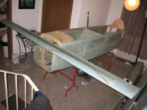
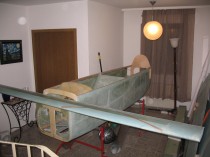
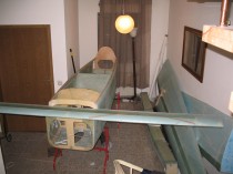
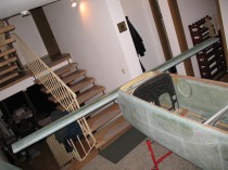
I got the canard in the house and test fitted it to the fuselage.  I was stoked at how it’s all coming together.  My antenna cables’ exit location from the canard was spot on.

Chap 12 - Mounting Canard (Mock-up)Chap 12 - Mounting Canard (Mock-up)


Chap 12 - Mounting Canard (Mock-up)

I have to say I was extremely pleased with the initial canard fitting!


Chapter 13 – Nose Gear Strut

I started today but doing some quick checks on the elevators to make sure I hadn’t screwed something up along the way . . . not that I’ve made a mistake yet, but there’s always a first time for everything! (He said facetiously).

I checked both elevators with the NC-7 jigs & they lined up exactly like they were supposed to.  It’s definitely an internal clearance issue between the NC-3 hinge edges and the bottom surface of the hinge insert (NC-2) slot.

I used the Dremel tool to carefully make the hinge slots wider (this is per plans, not an attempted remedy for the clearance issue above) by removing some of the tube siding at the end of each side of the NC-2 hinge slots.  I measured the hinge pin-to-LE on all the hinge assemblies and all were right at 0.49″-0.5″.

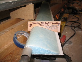
Finally, I double-checked the top contour on the elevators using Template H, not surprisingly call the Elevator Top Contour Checking Template.  (Note: You can see the result of the foam overlap onto the elevator tube having crumbled and broken off when I mounted the tube into the elevator foam with micro.  The channel for the aluminum elevator tube just wasn’t large enough, and the result was that most of the thin foam came off in the process.  This left a small depression where the foam should have gradually overlapped onto the tube.  This depression will of course be filled in with micro during the finishing stage).

Chap 11 - Checking the top elevator contour

Now, onto the real subject of this post: the Front Gear Strut.  Chapter 13 of the Long-EZ construction plans covers the Nose & Nose Gear.  I will of course be deviating from the plans in large measure since I will be installing Jack Wilhelmson’s EZ-Noselift electric nose gear actuator in lieu of the old mechanical system.  In addition, I will be constructing a longer nose using the Davenport design, which will change NG-30 gear housing/nose assembly and the forward bulkheads.  In doing so, much like the elevators & canard where I was using 3 sets of plans: Long-EZ, Roncz Canard, & Cozy Girrrls; for the nose I will also be using three sets of plans: Long-EZ, Wilhelmson’s nose lift, & Davenport nose design.

Step 1 of Chapter 13 is to add 2 plies of BID to the nose gear strut for reinforcement, in the same fashion as is done for the main gear with all its extra glass plies.  The BID plies on the nose gear strut are simply 3-sided layups in opposing directions (shaped like this: Π ) with the second ply overlapping the sides of the first ply.

To start, I screwed down a scrap piece of wood to the workbench as a mounting board.

Chap 13 - Nose & Nose Gear: Step 1I sanded & then 5-min glued the NG-1 nose gear strut (made of solid S-glass, just like the main gear) to the mounting board, with the aft side of the strut facing up.

Chap 13 - Nose Gear BID ReinforcementChap 13 - Nose Gear BID Reinforcement

I then glassed the first 1-ply BID layup onto the NG-1 nose gear on the Aft, Left & Right sides using fast hardener, since it was a fairly small layup.

Chap 13 - Nose Gear BID Reinforcement

Of course I then peel plied the entire layup.

Chap 13 - Nose Gear BID Reinforcement


Chapter 11 – Elevator Hinges

I started today by installing the elevator tube end inserts (NC-6) into the Outboard end of the elevators.

I lined up the stainless steel hinge pin, then marked & drilled a #10 hole for the setscrew. After the setscrew was in, I insured the NC-6 was even with the Outboard edge of the elevator tube & then drilled a #30 hole to set a PPC-42 Cherry Pop Rivet.

Chap 11 - ElevatorsChap 11 - Elevators Chap 11 - Elevators  In the picture below the stainless steel hinge pins are shown to Left of the elevators.

Chap 11 - Elevators  I gathered up all my NC-3 elevator hinges, 3 for each elevator.

Chap 11 - ElevatorsI then installed the SS hinge pin starting on the Outboard side of each elevator at the NC-6 tube end insert . . . then through the two hinge inserts (NC-2) and ending up at the Inboard side of the elevator.  [Note:  Again, I’m installing the Cozy Girrrl’s elevator torque offsets (shown below), thus there are different amounts of elevator hardware required than spelled out in the Roncz Canard plans.]

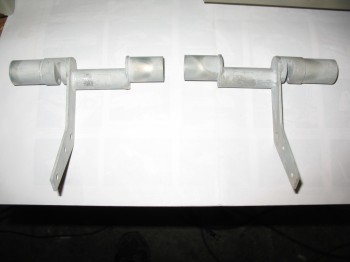
Chap 11 - ElevatorsChap 11 - ElevatorsChap 11 - ElevatorsChap 11 - ElevatorsChap 11 - ElevatorsChap 11 - ElevatorsChap 11 - ElevatorsChap 11 - ElevatorsThese pics show the Cozy Girrrl’s Elevator Torque Offsets.  These have the smaller offset tube towards the middle of the assembly which provides a more concentric movement, and thus less removal of fuselage sidewall material is required for elevator travel (as compared to the stock plans configuration) as this assembly pivots when the elevator controls are moved.  Obviously significantly less material removed and not having to have a decent-sized slot on each side of the fuselage greatly mitigates the amount of air (usually reported as “cold”) that sneaks into the cockpit.

Chap 11 - ElevatorsChap 11 - Elevators

Now back to inserting the hinge pin . . . note the hinge pin hole in the torque offset that I’m holding in my hand in the pic above.  

Chap 11 - ElevatorsChap 11 - ElevatorsChap 11 - ElevatorsSo, the hinge pin insertion exercise went fine on the Right elevator . . . However, the Left elevator decided to be a PITA & not be so cooperative.  It was as if some invisible force was blocking the hinge pin from going through the first hinge insert (NC-2).  I tried everything I could think of . . . then I realized something was blocking it, the bottom of the hinge insert trough that the hinge (NC-3) was supposed to slide into.  It wasn’t a clearance issue laterally left-to-right with the hinge pin, it was an up-n-down issue with the hinge not having clearance at the bottom of the hinge insert to be inserted far enough.

After messing around with it for another 1/2-hour or so, I grabbed my square file and filed the bottom of the NC-2 hinge insert trough.  Slowly but surely, that did the trick.  I’m not sure how or why this happened, but I needed to file down about 0.05″ to get the hinge “top” to freely pivot in the hinge slot.

Once I got that issue out of the way, I mocked up the hinges to their dense foam mounts on the canard.

Chap 11 - ElevatorsChap 11 - ElevatorsIn the pic below the Inboard hinge/torque offset looks drastically off from its associated dense foam mounting point on the canard.  The reason why is that the torque offset actually gets mounted much farther Outboard (in relation to the elevator itself, not the canard) than what I have mocked up in the pic. There’s quite a few inches of the Inboard elevator tube–along with some glass & foam as well–that gets removed to make this happen.

Chap 11 - ElevatorsChap 11 - ElevatorsChap 11 - Elevators


Chapter 11- Elevators (& canard)

I started today by “razor” trimming the elevator edges using the Fein saw.  In doing so, I ensured that the Outboard edges & ends were square.

Chap 11 - Elevators

I removed the glass that had been laid up over the NC2 hinge slots.

I then cut some peel-n-stick sandpaper into approx 5/8″ strips and stuck them to the edge of one of the aluminum straight “boards”.

I sanded the elevators’ TE with the new sanding board, and then sanded the LE glass overlap.

I cut the foam at the Outboard ends around the edge of the glass to prep for flox corners. I made up some flox, for the edge channel, then I micro’d what small area was left on the ends of the elevators.

Chap 11 - Elevators

I glassed a 1-ply layup on the Outboard end of each elevator.  Then I took a break and went to see a movie.

Chap 11 - ElevatorsChap 11 - Elevators

When I returned from the movie, I knife trimmed around the edges of the elevator end layups.

I snapped a few pictures of the canard as well.

Chap 11 - CanardChap 10 - Canard

Below are a couple shots of the canard antenna leads:

Chap 10 - Canard antenna leadsChap 10 - Canard antenna leads

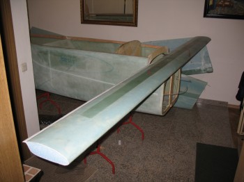
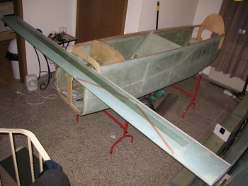
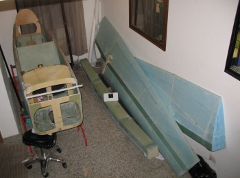
And finally, a shot of the fuselage, CS spar and wings in my climate controlled storage facility (yes, my dining room).

Fuselage, CS spar and wings stored


Chapter 10 – Skinning canard top

I started off today by hot gluing the outside corners of the canard jig that I had been messing around with yesterday while leveling the canard & ensuring it was straight.

I then cleaned up the spar: sanded, Dremeled, & prepped the LE & TE.
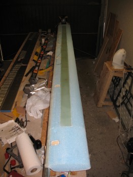
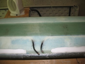
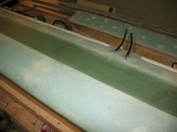
Chap 10 - Canard top glass prepChap 10 - Canard top glass prepChap 10 - Canard top glass prep

I then cut the antenna cable runs & installed the canard VOR & ILS antennas.
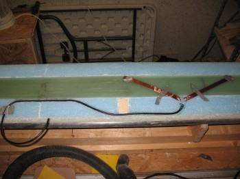
Chap 10 - Canard antennas installChap 10 - Canard antennas install

I vacuumed the entire top surface of the canard & made a final check of my preparations before starting the final main skin layup.

I used a mixture of fast hardener for the dry micro paste for all the heavy dings & divots, and around the installation of the antennas.  I used a ~50/50 mixture of micro & flox for the LE prep. Something I may not have mentioned before, but something I’ve noted to building buddies of mine is that my unofficial ratio is that for about every hour worth of glassing I do, it seems like I have about 8 hours of actual prep (NOT researching & studying the plans, etc.).  On this layup it took about an 1-1/2 hours just to finish prepping all the foam with micro.

I used fresh epoxy to wet out the LE, spar cap, TE glass.  [Note:  I think it’s worth reiterating that glass surfaces always get a coating of epoxy (normally) or flox (occasionally), which are structural, but never micro–which is not structural–in between the layers of glass].

I glassed 1 long single ply of UNI, a 4-piece layer of BID, and then 2 more long single plies of UNI… with 2 small holes in the middle for the antenna leads ~ 5.5″ & 4.0″ Left of CL.
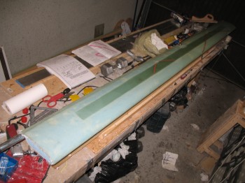
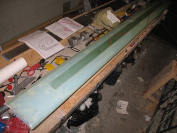
Chap 10 - Canard top glassedChap 10 - Canard top glassedI used toothpicks to the hold antenna leads straight while glassing the individual skin plies, and then used a makeshift taped Popsicle stick contraption to hold it at the right angle after all the top skin was glassed and the antenna lead area was peel plied.

I also specifically peel plied the Left Outboard LE area that was damaged by the foam being removed.  It’s a slight flat spot that’s about 5 inches long, which I will just add a 2-3 ply glass patch and then shape it afterwards after this main glassing is completed.
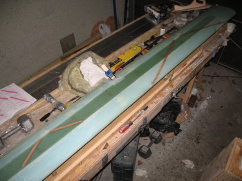
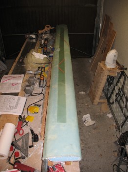
Chap 10 - Canard top glassedChap 10 - Canard top glassedI checked the layup about an 1-1/2 hours after I finished and found a bubble a little over 1 inch long & about 1/2″ wide right over the edge of the spar cap, on the Left side about 6″ Inboard from the seam with the 11″ tip extension.  It looked like it might be internal air off-gassing through the seam of both the spar cap and maybe even up through the top of the internal shear web.  I “popped” the bubble with my scribe, added just a dab of wet epoxy and re-squeegeed out the bubble.
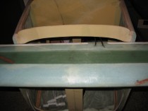
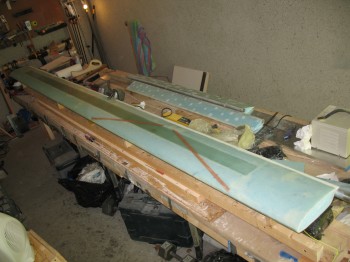
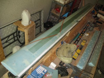
Another area that I wasn’t overly happy with was the contour of the TE, after using the contour checking template.  Although I had built to plans, there was a trough/depression running down the entire length of the TE, not unlike the TEs of the main wings or winglets. So, while not called for in the plans, I filled in the TE trough with dry micro while the glass was still tacky and not yet cured.