Chap 8 – Lower Seat Back Layup

I started with a list of about 10 things to get done today.  Well, I finished 2 of them! Between getting a late start and going out to dinner with friends this evening, I was merely able to get the lower seat back glassed.

I prepped the 1/4″ thick x 1-3/8″ yellow foam addition by adding a couple of extensions covered with duct tape to the outer edge of the yellow foam piece.  The reason for these extensions is that when they’re removed after the glass cures there will be about a 1/4″ glass overhang for the connecting foam piece that will be glassed in from the top side seat back assembly.  In short, this glass overhang will be the meeting point between the lower seat back assembly and the upper seat back assembly.

Lower seat pack piece

I then scurried up a piece of BID for the layup.

Layup Glass Prep

And some for the BID tape that I’ll be laying up in the corner to add strength.

BID tape pre-preg prepped

I micro’d up the foam and added a fillet in the corner.

Foam micro'd

I laid up the large ply of BID first, then laid up the corner tape.  Once that was all finished I peel plied the lower edge and the corner tape.

Layup finished

A few hours later I razor cut the piece, pulled the peel ply and cleaned it all up.

Trimmed & peel ply pulled

Below shows the 1/4″ piece I added to the lower seat back piece, and the glass overhang on the aft side of the yellow foam.

Under cross bar piece

Of course I mocked up the newly glassed piece along with the other seat back components.  Below you can finally see the notch for the roll bar’s rectangular cross bar.

Latest seat back pieces mocked up

Latest seat back pieces mocked up

I added the cross bar so I could see how it all looks together.

Latest seat back pieces mocked up

Here’s a shot from from just a tad bit forward so you all can see the front edge of the cross bar aligned with the front edge of the lower seat back.  Looks like the fit should be pretty darn good.

Latest seat back & crossbar mocked up

And here’s the final mock-up shot of evening.

Latest seat back & crossbar mocked up


Chap 8 – Prep, prep, and more prep!

I would love to say that I got some really cool layups in today, but I can’t.  Today was all about prep.  And I mean I literally spent about 10 hours prepping a myriad of nitnoy things to get chapter 8 knocked out.

I started by spending about a 1/2 hour sanding the face of the seat back shelf so that it was as straight & level as possible.  Sometimes I feel more like a sculptor more than an airplane builder!  Once it was level, and I had it in the fuselage, I just wasn’t sold on the sharp edge that would make up the corner of the back of the seat and the new seat back shelf (headrest base) that I was working on.  I decided that I was going to radius that corner with a 3/16″ round-over router bit.

I clamped the piece to the work bench, and due to the edge being so sharp & the angle so great, I had to use a guide to keep the bit at the right position on the cut.

Radius'ing seat back edge

Here’s a shot of the aft side 3/16″ router cut on this piece.

Radius'ing seat back edge

I then radiused the front edge 1/8″.

1/8" radius seat back front edge

I mocked it up to check out the look of the radiused edges, and was happy with the results.

Seat back piece mock-up

Seat back piece mock-up

After I checked the seat back piece, I then radiused the top edge of the lower seat back piece using the same 1/8″ bit I used on the front of the piece above.

1/8" radius on lower seat back piece

Here it is after I routered the edge.

1/8" radius on lower seat back piece

I then added that piece into the mock-up.

More mock-ups

I turned my sites on getting the aft hard points for the headrest prepped so it’s ready to glass either later this evening, or tomorrow.  I measured out and marked the positions of the 2 aft headrest bolt holes.

Drilling aft headrest bolt holes

I then drilled the holes.

Drilling aft headrest bolt holes

Next, I started making the hardpoints that will sit opposite these aft bolt holes in the headrest.  These hardpoints will be mounted in the foam that makes up the seat back shelf, much in the way that the original Long-EZs had their seat belt hardpoints configured.

I started by grabbing some 1/4″ Birch Plywood to use as my hardpoints.  I’ll also be using the K1000-3 nutplates.  I marked up the first hardpoint using the K1000-3 as the determinant for my dimensions.

Headrest bolt hard points in seat back

After I drilled the center hole large enough that the stem of the K1000-3 nutplate would fit inside, I traced the nutplate and used my razor knife to make a pocket for the nutplate to fit in so it will sit flush as its embedded inside the foam mounting point.

Headrest bolt hard points in seat back

Here’s the 2 nutplate assemblies that I’ll embed so that they become the aft hardpoints for the headrest assembly to bolt to.

Headrest bolt hard points in seat back

And the reverse sides.  BTW,  I intentionally made these slightly different sizes in order to tell them apart and not get them confused during the installation.

Headrest bolt hard points in seat back

I set the headrest’s aft hardpoints aside and made up 4 dowel guide pins to help the new seat top with the existing seat, especially as it’s curing.

Seat back alignment dowels

Here’s a picture of them installed in the new seat top piece.

Seat back alignment dowels installed

With the seat top ready to go, there was still something I needed to complete before the seat top gets glassed in permanently.  The roll bar will be bolted in from the inside of the longeron out using 1/4″ bolts at the very front of the side roll bar longeron rails, and at the aft end of the rails.  In the middle area, where the new composite seat assemble will be built, I won’t have access to install a bolt there, since the entire area will be encased with the seat back assembly.  So the third, and middle hard point for the roll bar will be a 3/16″ screw that will be installed from the top to the bottom of the longeron.  Since the longeron isn’t that wide, I will be using a 3/16″ screw to ensure a lot of strength, but also minimize the cross section of the hardware installed in the longeron.

Again, since I won’t have access to that area, I can’t secure the screws with the traditional nuts & washers.  For this endeavor, I’ll again use a K1000-3 nutplate. However, instead of mounting it into wood, I’ll be riveting the nutplates to 1/8″ 2024 aluminum backing plates.

Rollbar side rail middle bolt hardpoint

Here’s the nearly finished set.

Rollbar side rail middle bolt hardpoint

And from the other side.

Rollbar side rail middle bolt hardpoint

Tomorrow I’ll shape the edges & then Alodine the aluminum before riveting the nutplates to the pieces.

I also spent a decent amount of time figuring out my hardware requirements for the rollbar assembly.  I was curious about the weight of the hardware, so I threw them all on the scale: 0.17 of a pound.  Not bad!

Entire rollbar attach hardware

With that out of the way, I started mocking up the headrest on the seat back shelf so I could determine exactly where the headrest hardpoints needed to go.

Determining rear headrest hard point positions

I measured, eyeballed, laser-sited, and double-checked the hardpoint positions before pulling the trigger on marking them up.

Determining rear headrest hard point positions

Here’s a shot of the headrest hardpoint positions prepped on the seat back shelf.

Prepping headrest aft hardpoint locations


Chap 8 – Seat Back & Headrest

I started off today cleaning up the layups I did yesterday on the seat back shelf/headrest base & the lower seat back 0.7″ add-on piece.

Finished parts round 1

I then pulled the peel ply on the lower seat back piece & cut out 2 small rectangular pieces to fill in the notch on each upper corner that originally allowed for the piece to set up tight against the longerons (basically the stock style seatback piece that gets glassed to the seat back at the lowest point of this whole endeavor).

Lower seat back mock-up

I then went scrounging through my old BID pile to find 2 acceptable pieces of BID to use for these next two layups.  I’ll pre-preg the 1-ply BID for the underside of the upper seat back shelf where it joins the gap fill piece that will make up the new top of the seat (replacing exactly what I cut away a couple of years ago!).

Glass prep for two layups

I started by micro’ing all the pieces (4 total) of the lower seat back, covered it with saran wrap and then weighed it down to hold it’s shape (you can see it in the background below covered with a veritable smorgasbord of chemicals!).  I had already wetted out the pre-preg when I started on the lower seatback piece, so I then used the small amount of leftover micro & added a boatload of flox to it to make up the fillet for the seat back/gap fill piece.

Flox (& flocro) fillet

I did a final prep on the 1-ply BID pre-preg, cut it to size (2″ BID tape) & then laid it up.

What's the wind direction???

Here’s the final layup, peel plied and curing.

Seat back cap & seat gap piece

With the micro on the lower seatback piece significantly more gummy, I laid up 1 ply of BID on what was 4 completely separate parts just a half hour ago.

Lower seat back piece

I then went into a completely different direction, breaking out the 1 x 1 inch square 4130 tube that will serve as the side rails for the roll bar assembly.  I know a fair number of my compadres use a rectangular piece to start so that they get a full 1-1/2″ coverage on the entire inside of the longeron.  But I really want to save as much weight as possible on the rollover assembly (ok–everywhere) and lopping off a 1/2″ strip of 4130 steel on a total run of about 24″ will help quite a bit.  I may be somewhat more sensitive to saving weight on the rollover where I can–without compromising safety–since I’m adding well over a pound of weight into the mix by actually having a headrest.

Roll bar side mounts (longerons)

The advice I got from Marco on cutting this 4130 steel was to use my table saw with a cutoff wheel, which I will most likely do for the 4130 steel that I’ll be using for my engine mount extrusions (vs 2024 aluminum… at least on the top mounts).   With it being a very windy day, and with the amount of energy I have to expend on pulling my table saw out of the external shed, change the blade, etc. I chose to go into true experimental mode (read: lazy) and use my Dremel Tool with a cutoff wheel to rip the square tube into 2 pieces of 4130 angled steel.

Roll bar side mounts (longerons)

I know I’ll be shaping & cleaning up the edges as the rollbar build progresses, so I wasn’t overly concerned about some slight waviness in my cuts.

Roll bar side mounts (longerons)

It took me about 20 min & 3 wheel changes to cut 24″ of 4130 steel.  And here’s the final product(s):

Roll bar side mounts (longerons)Moving on . . . since my MGS 285 slow hardener was taking it’s sweet time on curing, I decided to go ahead and install the screws on my rollover assembly.  I have a bunch of the same 82° Stainless Steel Allen head screws that Mike Melvill used in doing a major makeover on his Long-EZ years ago.  He gave the part # in a CP, so I ordered a bunch of them thinking I would use them as he did.  Well, tonight was night!

I clamped a piece of scrap wood behind the glass to prevent any blowouts from drilling the holes.  Each hole was a 4 step process: pilot hole bit, ~1/8″ hole bit, #10 hole bit, and CS  bit.

Headrest Screws

Here’s the final drilling on the top headrest piece hinge attach holes.

Headrest Screws

And no blowouts on the inside (a lesson I learned by NOT following the plan’s guidance while drilling some of my NG30 screw holes…. luckily Marco quickly sent me page & verse denoting where I had violated the law of Burt … again, live & learn!)

Headrest ScrewsAnd here’s the Melvill screws installed.  Not bad looking at all!

Headrest Screws

And from the inside . . .

Headrest Screws

And then the base of the headrest . . .

Headrest ScrewsHeadrest Screws

And all together!

Headrest ScrewsHeadrest Screws

Here’s a shot of the finally cured & cleaned up seat back & spacer piece.

Seatback shelf & gap fill piece

Also, a shot of the lower seat back, also cured & cleaned up.

Lower seatback piece

And now for this evening’s finale . . . mock-ups!   I started by placing the seatback shelf in its position on top of the current seat (whose straightness was significantly enhanced by the post cure).

Seat back piece mocked upI then added the headrest.

Headrest mock-up on seatback baseHeadrest mock-up on seatback baseAnd a shot of the lower seat back in its approximate position.  Ironically, I will most likely have to notch this piece as well on both sides for it to fit under the longerons.

Headrest mock-up on seatback base

I thought I would also show a few pics of the rectangular rollover cross bar with the the roll bar in its approximate position.

Headrest & rollover mock-up

A head-on shot.  Of course the cross bar will sit further aft, about where the expander is currently positioned.

Headrest & rollover mock-up

And the final shot of the evening focusing on the rectangular rollover cross bar & the headrest sitting on the seat back base.

View of rollbar cross bar


Chap 8 – Headrest & Seat Base

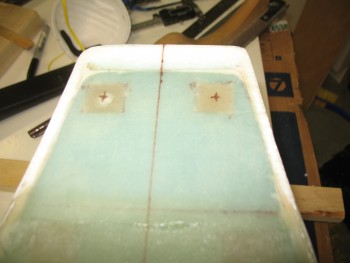
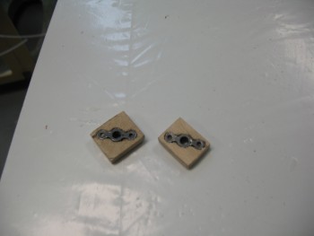
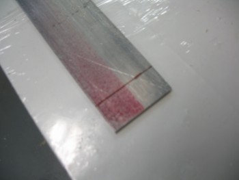
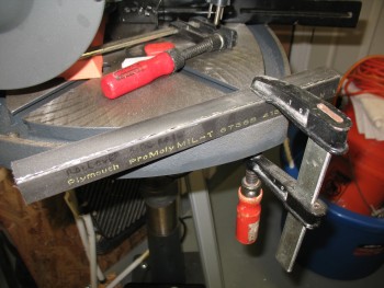
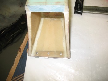
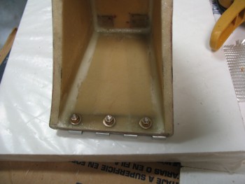
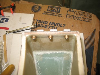
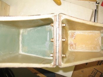
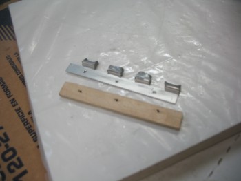
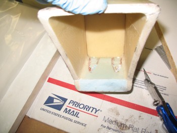
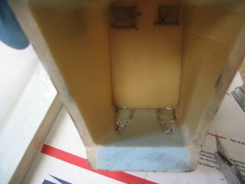
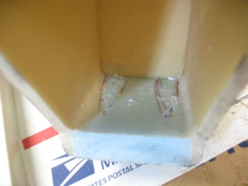
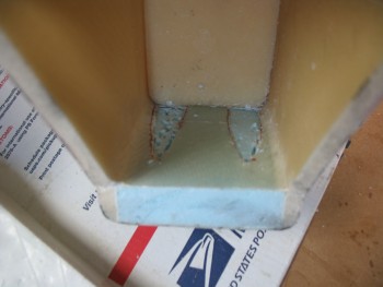
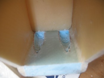
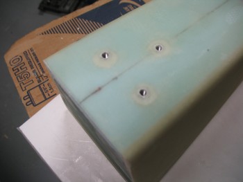
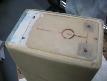
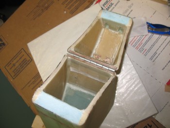
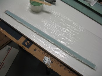
This morning I knocked out the BID reinforcements for the hinge screws on the internal side of the headrest.  I used 2 plies of 1/2″-wide BID for the main reinforcement on each side, then followed that up with a 3/4″-wide layer of BID for both a final third ply for strength and as a transition to existing glass.  Since I pre-pregged these BID tapes I had 2 separate pre-preg setups: one for the 1/2″ tapes, and one for the 3/4″ tapes.  Here’s the 1/2″ tapes I started off with, each with 2-plies of BID:

1/2-inch 2-ply BID pre-preg strips

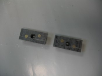
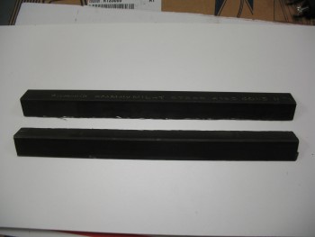
Here are the hinge screw reinforcement layups finished & peel plied:

BID reinforcement strips for screwsBID reinforcement strips for screws

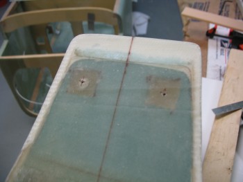
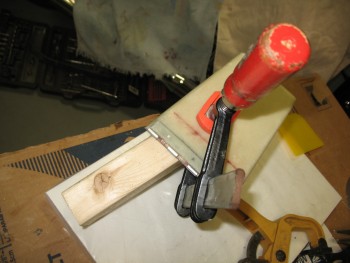
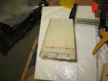
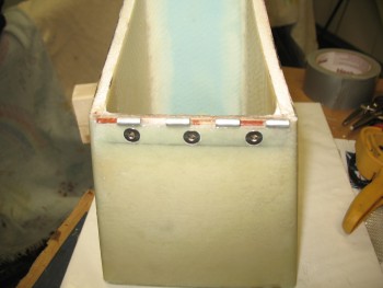
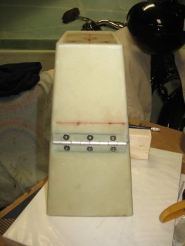
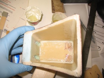
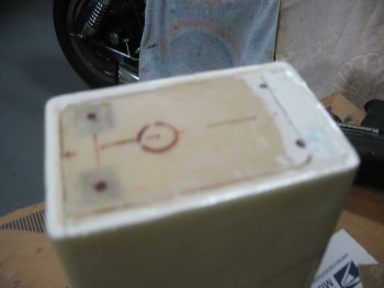
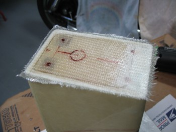
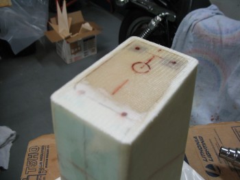
I had to run out and do a bunch of errands, so when I got back home I started on the seat back build.  I’m going to jump ahead here to my final layup of the evening, which was adding a 1-ply reinforcement BID tape for the hinge screws on the external side of the headrest on the front face.  I had some epoxy left over from the layups below, and had already been kicking around the idea of adding a ply of BID since I really want to counter sink the screws flush on the front face.   I figured I would give the screw heads just a little bit more meat to grab onto.

headrest front face hinge reinforcement

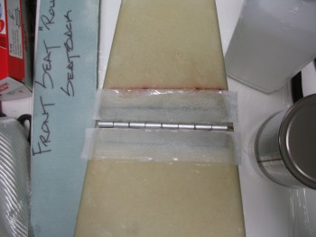
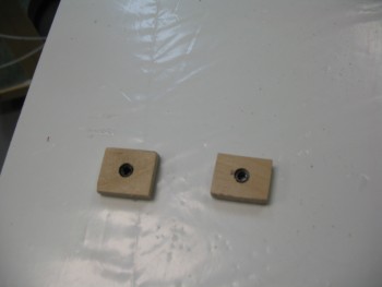
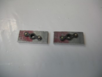
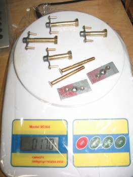
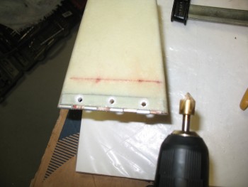
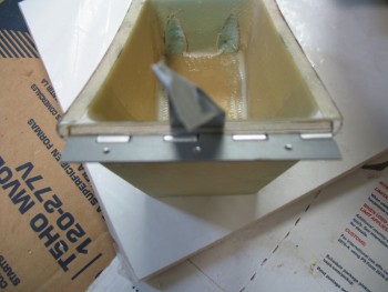
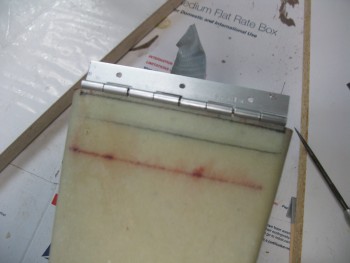
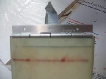
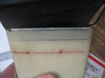
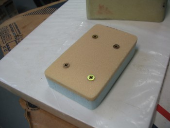
With my reinforcement plies of BID in place on all sides of the hinge, tomorrow I’ll install the 6 screws, washers and nuts to the hinge assembly.

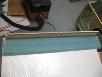
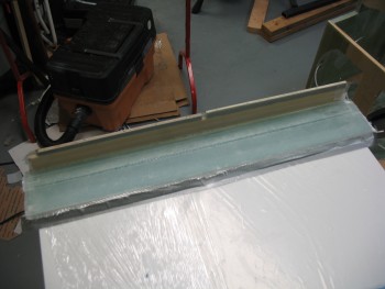
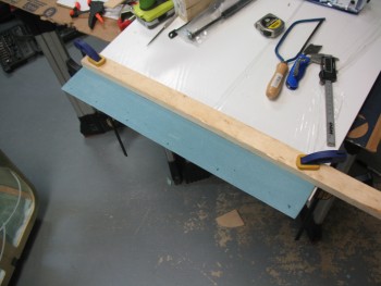
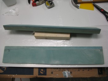
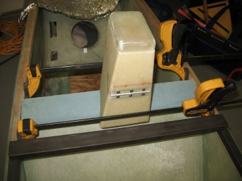
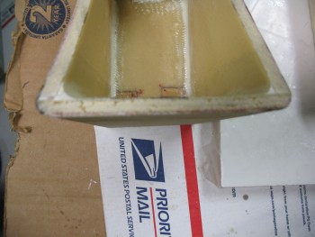
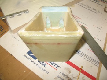
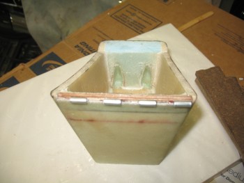
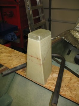
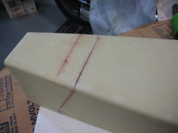
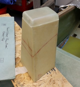
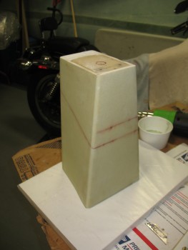
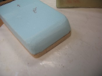
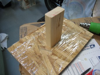
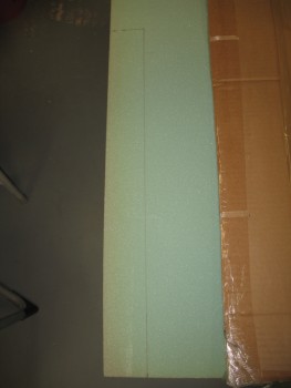
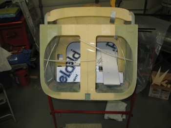
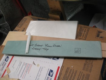
My first order of the day for the seat back composite assembly was to cut out some of the required foam I needed.  Since the base of my headrest and rollover assembly is a total of 5.8″ wide–versus 4.5″ stock–it requires that I add a little height to my very front foam piece that makes up the seat back as it dives into the existing seat… the piece that makes up the lowest installed component of this whole assembly.  I had originally made that piece to stock dimensions out of 3/8″ foam.  I had also glassed it with 1 ply of BID on one side. Now to make up for it moving forward slightly, and thus down the seat face slightly, I need to add a 0.7″ wide strip of 3/8″ foam to the top of it.

Extension strip for front piece

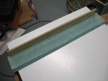
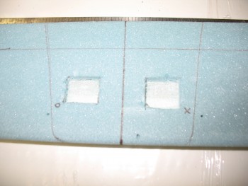
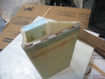
I cut the 0.7″ strip of 3/8″ foam & then quickly positioned it to ensure I was on track.  As you can see from the pic below, I’ll have to fill in the notches that were originally meant to allow clearance for the longerons.

0.7" extension for back rest piece

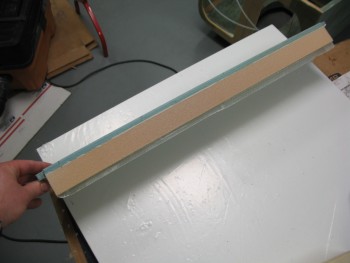
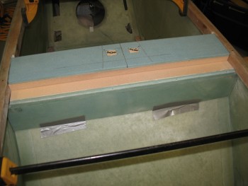
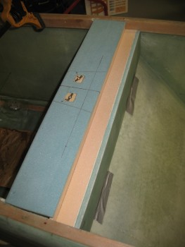
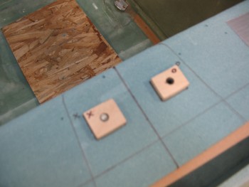
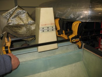
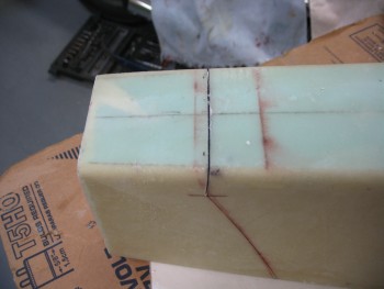
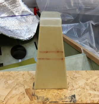
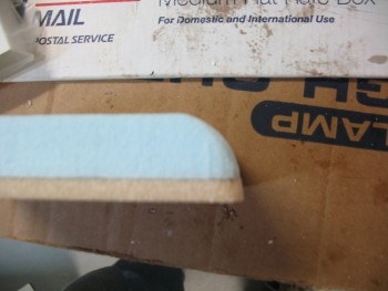
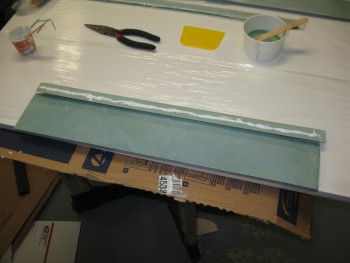
I then marked up the 3/4″ piece of foam that I would use to fill the gap from the existing front seat top & the 3/8″ thick foam cross piece that makes up the base of the headrest, somewhat like the original plans headrest base that is essentially a shelf that traverses the seat back from longeron to longeron.

Gap fill between seat back & base

Gap fill between seat back & base

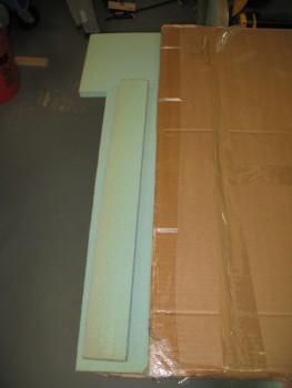
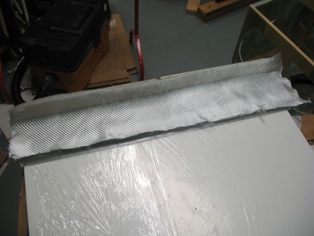
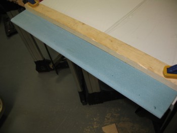
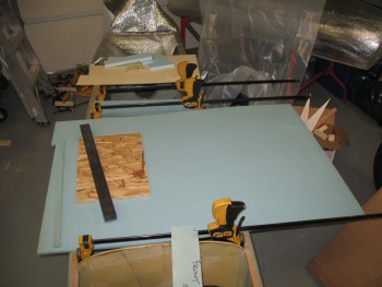
I then took the 3/4″ foam and piece of 1/4″ foam that I’ll be using and cut them on my table saw.  Here’s the resulting piece that I’ll use to fill the gap for the seat back, set in place.

Cut seat gap fill piece

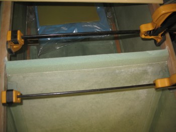
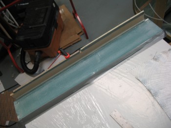
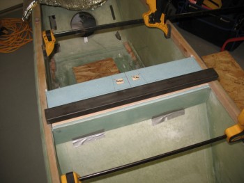
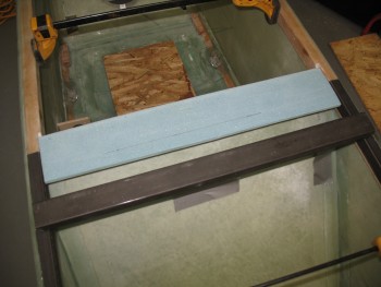
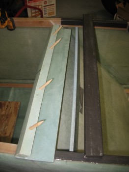
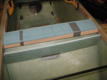
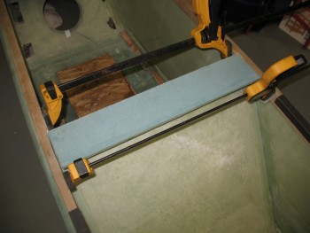
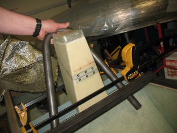
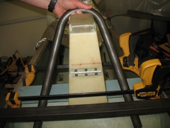
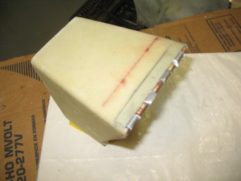
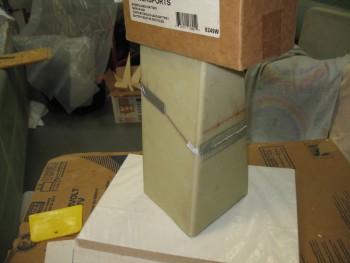
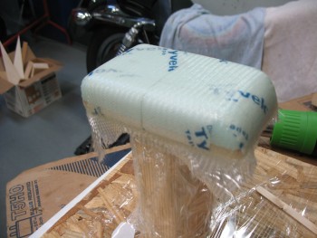
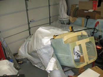
You may note the clamps in the picture above being used as expanders for the fuselage. Since my fuselage is a bit more curved than a stock fuselage, and since I also cut the top of the seat off in my original plan for the seat back & rollover design, the front seat has developed a very slight curve forward in the middle.  I put those expanders in and have been increasing the pressure every few hours as I was getting ready to post cure the seat to straighten out the seat back as much as I can.

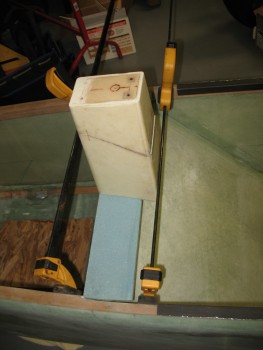
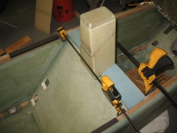
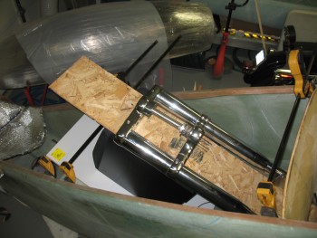
I prepped the seat back for post-curing by getting the nose as high as possible so that the weight would be concentrated on the seat back.  Since I don’t have my workout weight set here with me, I had to resort to hunting around for some fairly heavy objects, thus the weird sight below of an old sub-woofer and the quite hefty front forks for my chopper project (that were damaged in the move btw).

Weight for seat back during post-cure

I put some foam insulation heat shields at the front of the fuselage to trap as much heat as I could.

Heat panels inserted

Then I placed my trusty shop heater in the back seat on a small piece of plywood, and covered the fuselage with the same material I used in Germany for the massive 24-hour Uber fuselage post cure.

Post curing front seat backPost curing front seat back

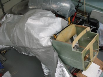
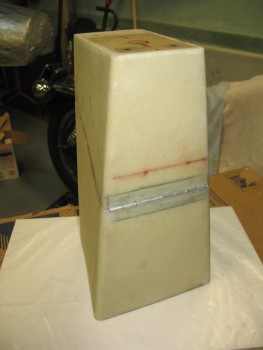
With the fuselage covered and the seat back (hopefully!) getting realigned back to where it should be as it baked at almost 120° F (see pic below), I started in on glassing the 0.7″ strip of 3/8″ foam and the top of the seat back to the spacer that will fill the gap on the existing seat.

Shop 80.8 F .... post cure 118.9 F

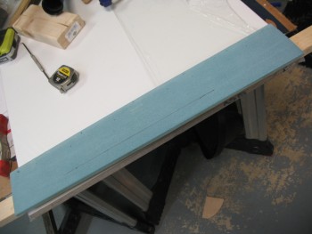
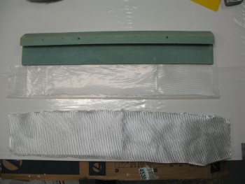
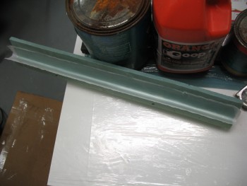
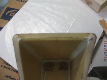
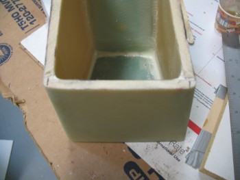
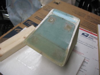
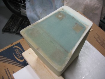
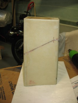
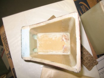
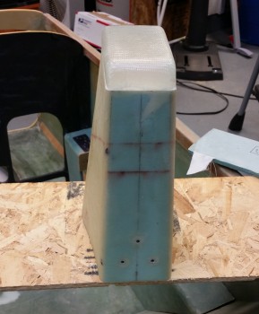
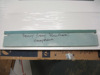
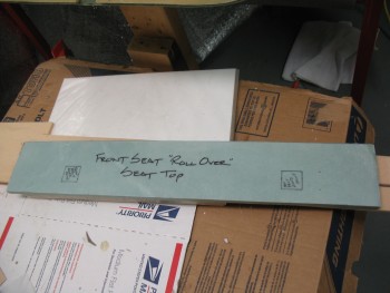
I started by pulling the peel ply off the seat back base piece.  I glassed this thing back in the Summer of 2012, and the peel ply still came off quite nicely.  Also, I am actually using this piece upside down compared to how it was originally meant to be used.

Original 2012 seat top

Peel ply finally coming off!

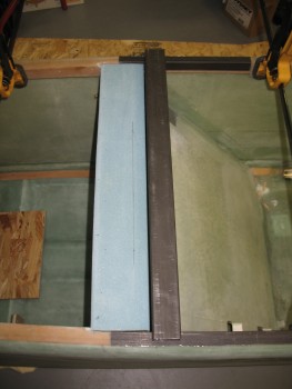
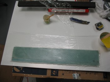
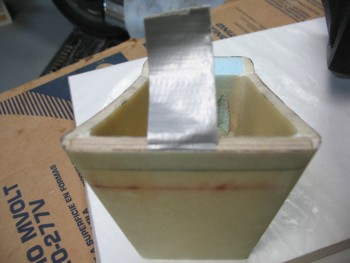
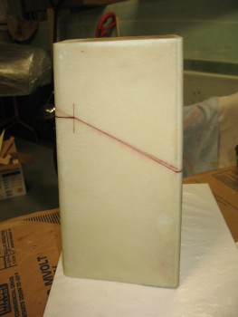
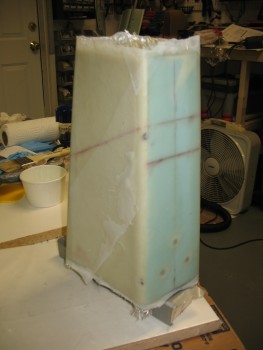
I mocked up the gap-filler piece to the seat back base, and then when I liked what I saw I pinned it together using finishing nails.

Seat top nailed to gap fill pieceSeat top nailed to gap fill piece

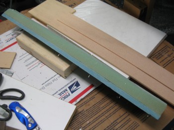
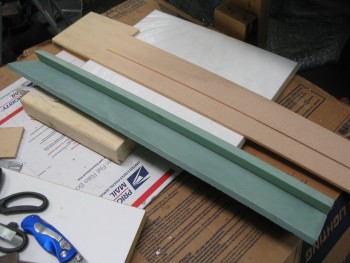
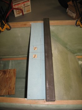
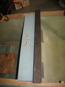
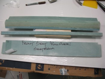
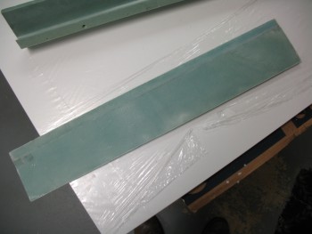
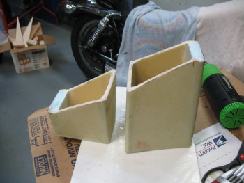
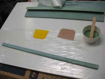
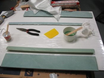
Here are the 2 parts of the seat back that I’ll be glassing tonight: a) the 0.7″ strip that will be added to the back rest piece, and b) the seat back base with the gap filler.

Today's glassing tasks

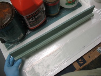
Now, I’ll let you in on a dirty little secret of mine.  I have yet to touch any of my new MGS 285 epoxy.  Since I don’t consider the headrest as a structural piece, I’ve been using the 4 year old MGS that I had originally left with Marco.  I have to tell you, that old MGS 335 is still kicking and I see no diminished effects in strength or hardness.

Thus, I broke out a new can of MGS hardener and prepped it in one my squeeze bottles. The pic below doesn’t do this stuff justice in how brilliant the blue is for the MGS 285 hardener.  It really is stunningly brilliant stuff.

Fresh, new MGS 285!
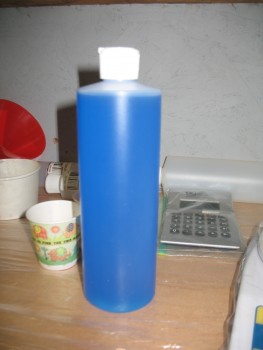
Now, I will say the big difference between that old stuff and this new MGS 285 (which is a significant difference between MGS 285 and 335 anyways) is that the 285 is a dream in its usability.  It flows like water & it wets out so amazingly well.  It’s like the difference between driving an old reliable truck or a beautiful sports car.  Both work and do what they’re supposed to, but one drives like silk…. as does the MGS 285.  Great stuff!

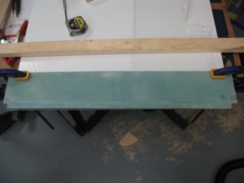
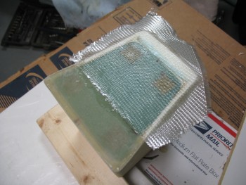
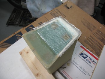
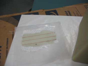
As for my layups, I started by applying microslurry to the 0.7″ strip.

Micro'd .7" extension for back rest

Then laid up 1 ply of BID:

BID on extension for back rest

BID on extension for back rest
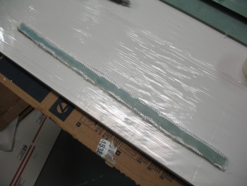
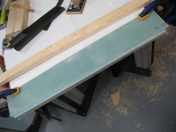
And then peel plied it.

Peel plied extension for back rest

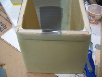
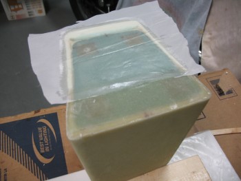
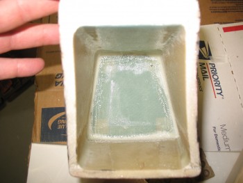
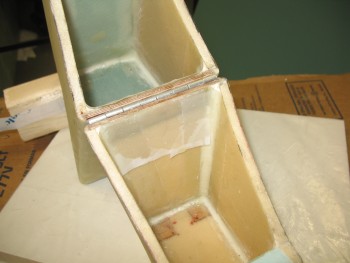
I then started on the seat back base & gap filler.

Glassing seat top & gap piece

I mixed up some flocro (micro with about 1/2 flox) to attach the gap piece to the seat back base.

Flocro gap piece to seat top

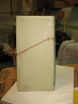
After messing around with ensuring the pieces were aligned & all the excess flocro was removed from joining these pieces, I laid up 1 ply of BID on what will be the back side & top of the back seat, something along the lines of the rear top corner of a “7” . . . of course including the top of the “7” as well.

Back of seat & gap piece...1-ply BID

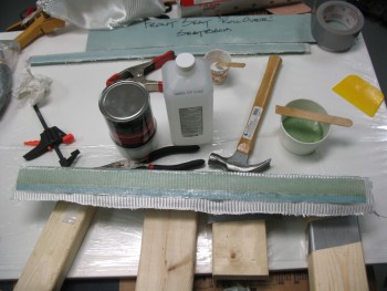
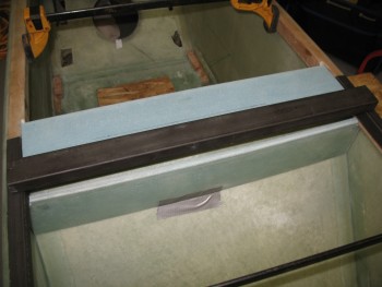
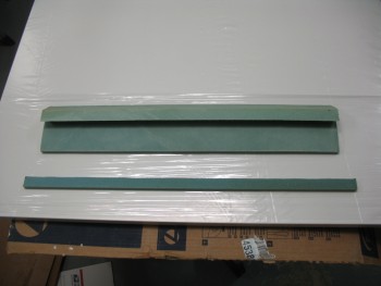
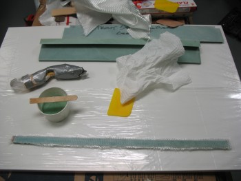
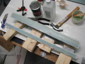
Below were the 2 “to-do” items on my list tonight, now glassed and curing:

Glassing tasks completed!

Tomorrow I’ll check the outcome of my post cure on my seat back, and then also start cutting some 4130 steel in preparation for the mock-ups and fittings required before I can finalize any layups on the composite seat back structure.


Chap 8 – Seat back

Today I awoke to what was supposed to be a nasty day, but turned out to be a beautiful day for flying.  I was getting together with my lifelong friend Kevin, who stayed with me a bunch in Germany and helped me glass the left wing.  Kevin just got back into town permanently after having done the multi-year contractor gig over in Pakistan since about the time I was returning to Germany from Tampa in April 2013.  Long story short, I took him flying on a hop over the Chesapeake Bay to Cambridge, Maryland where we did a few touch-n-goes and a couple of landings before heading back.   Amazing how a forecasted crappy day turned out to be almost as perfect as you could ask for to fly.

Back in the shop, I went into planning mode.  With just a couple small odd-n-end things to do on the headrest, I turned my sights to the seat back configuration.  As I said in my video, the seat back will be close to the original plans in that there will be about a 4″ wide glass shelf, or headrest base, that meets the seat back at the aft side, will traverse across the fuselage from longeron to longeron, with the forward edge abutting the rectangular 4130 steel crossbar that will make up the primary base of the roll bar.  The rectangular crossbar is 1.75″ wide, so add that to the 4″ glass base that sits directly aft of it, and we get an overall flat surface area going across the back of the seat of 5.8″ wide.

Coincidentally (or not), the headrest assembly is 5.8″ deep at the base.  I don’t have any pictures of all this yet, but you can see that the aft 2/3 of the headrest will sit on the 4″ glass base, with the forward 1/3 of the headrest sitting on the rectangular crossbar.  Two (2) screws will secure the headrest to the glass base, and two (2) screws will secure the headrest to the rectangular crossbar, for a total of 4 screws securing the headrest to the base structure of the seat back.

So tonight was all about figuring out the composite structure for the seat back area.  If you take Burt’s original headrest configuration, and lopped off the triangular headrest so that you were just left with the base of it, you would essentially have what I am designing right now.  One other key modification that you would have to do to the original plan’s seat back, is to make a notch 1″ down and 1.75″ deep/wide at the front corner of the plan’s headrest base to allow for my rectangular metal crossbar to fit in there.

I accounted for every piece I was going to need, while assessing the pieces I had already made during the Summer of 2012 in Germany.  I will also need to widen one of my 3/8″ foam pieces that I have glassed on one side, and cut out some foam pieces that will be wide enough to go across the fuselage.  I pulled some 3/4″ & 3/8″ sheets of Divinycell out of storage in preparation for the seat back construction and confirmed I had all the materials required on hand.

Obviously once I get the headrest base/seat back glassed I can start actually welding the 4130 steel rollover assembly together.

My goal is to have Chapter 8 completed by the end of March.

Chap 8 – Hinge Construction

Today I finally finished installing the hinge on the front face of the headrest.  I started by digging out the foam from the hinge mounting area on the top part of the headrest.

Removing foam

I dug out as much foam as I could using the razor knife and then I switched to using the Dremel tool.

Prepping foam for hinge

As I got the foam dug out to the proper depth it was obvious that both the plywood insert and the hinge flange would not both fit width-wise, so I shaved a few more layers off the plywood by the approximate width of the hinge flange.  I had already shaved off a couple of layers off the plywood previously, but it clearly required another thinning.

Testing plywood insert

Testing hinge & plywood insert width

Before I thinned the plywood insert, it was so tight that I had to add tape to it in order to remove it.

Prepping hinge & plywood insert

I measured the hinge barrel width at 0.180 inch, so I simply halved that to remove 0.090 inch from the outer glass layer on both the top & bottom hinge mount, to center the axis of the hinge along the line between the top and bottom parts of the headrest.

Fitting hinge

Below you can see where I cut out 0.090″ for proper hinge positioning.

Checking hinge fit

Hinge notch

After mocking up the plywood insert & the hinge flange to ensure a proper fit, I mixed up some flox using fast hardener and slathered it into the hinge area.

Hinge area floxed

I also cut 4 pieces of duct tape to protect the holes at each end of the respective tabs on the hinge.  I then inserted the plywood insert & the hinge into the slot that I created on the front face of the upper portion of the headrest.

Hinge installed & floxed

While the upper headrest portion’s hinge assembly cured, I started prepping the hinge area on the lower headrest structure.

Hinge area marked

I tested the width & fit of the plywood insert in the same way I did on the upper headrest structure.  The plywood insert for the lower headrest structure needed to be thinned down as well.

Hinge wood insert test

As I was ready to pull the trigger on the lower hinge, I double-checked the first hinge assembly.

Hinge mounted & floxed

Having used fast hardener & then putting the heater on it had it cured in no time flat.

Hinge mounted & floxed

Since the top hinge half was cured in place, I used it as a template for the bottom to get a near-perfect fit.  I taped a strip of packing tape across the abutting plywood inserts.  I then floxed in the lower hinge and gave it about 20 minutes to cure before I mounted the top hinge half to the bottom hinge half.

After ensuring that no unwanted flox was getting into places it wasn’t supposed to, I ensured the upper & lower headrest assemblies were aligned.  I then taped the parts together with duct tape and to minimize any gaps I weighed down the entire structure.

Curing hinge assembly

After 30 minutes passed with the headrest in front of a heater, I removed the tape and weight to check the rotation of the hinge, and to make sure that there was no flox gumming anything up.  There was a few bits of flox here & there that I removed with a toothpick, but the hinge rotation was great and all looked good.

Finished hinge construction

Here’s a quick video discussing the headrest hinge:


Chap 8 – New Base “Lines”

Ah, yuk-yuk!

I remembered another “mundane” thing that I needed to do before I actually get to installing the hinges, and that is to finish the very bottom of the headrest by adding 1 ply of BID to the face of the base to cover all the exposed foam and to further connect the base piece to the headrest sidewalls at the aft half of the headrest base.

I started by cutting the foam out along the edges to create micro wedges to reinforce the corners.  Again, if this was a piece that I wanted to have higher structural integrity, I would be using flox.  But since I want to provide added strength at the corner edges while still keeping it as light as possible, I’ll be using micro.

I of course got over halfway through getting the micro into the angled troughs I had made when I thought about taking any pics of my progress.

Making Micro CornersSince I previously added a number of plies to the front half of the headrest base to get it to sit level, I will simply overlap the last ply of that previous layup with this piece of BID.

1-ply BID layupAfter wetting out the BID I of course trimmed the edges down to about a 1/4″.

Layup trimmedAnd as is my MO, I added peel ply.

Peel plySo here it is in its trimmed & completed glory.

Peel ply removed & all trimmed up And here’s a quick shot of the headrest up to this point.

Another quick mock-up

Now, I should seriously be able to get to the headrest hinges on my next build session!

Chap 8 – Headrest Hack Job

After a day away from the project I was ready to jump back into it full bore today.   And I did, AFTER I jumped through some hoops to get an Instrument flight lined up with my flight instructor.  So after an hour of partial panel flying while wearing the beloved foggles, and a quick early dinner, I finally found some time to get some glassing done.

My goal for the evening was to embed the hinge halves into the top & bottom of the headrest (you’ll see what I mean below) along with the associated 1/4″ plywood hardpoints.  I had originally drawn the cut lines on the side of the headrest as simply straight diagonal lines, but after thinking on it more I realized that both the front & rear faces would need to be cut straight.  The front required a straight cut for the hinge installment to be optimized and the rear face needed to be cut straight because I want to install some type of lock mechanism onto the back of the headrest to allow me to secure a few small things while away from the aircraft at fly-ins, etc.

Thus, I rewickered my original plan(s) & redrew the cut lines.

New cut marksNew cut marksI then got out my trusty Fein saw and went to work.

First cut on faceRear face cross cutThe cuts were a little tougher to make at the corners than I expected due to the micro fillets, making them all just a little bit rougher & less razor-straight as I wanted them to be.

Falling to pieces!  yuk-yuk

Of course they’re still perfectly workable & the lines looked good when I put the two halves back together.

Cutting complete

Again, my goal was to embed the hing halves, but then I realized there was some more pressing, less sexy glassing that needed to get done.  Both the top antenna shelf and the bottom base pieces required some micro fillets in the corners and some BID tapes to finalize the installation of these pieces.

As I started prepping the layups for the top antenna piece, I came across another minor issue that I needed to resolve: the location of the rear mounting screws for the GPS antenna falls right on the edge of the inside, rear face of the headrest.  Since the rear foam is 0.8 inches thick, it’s in the way of the rear two screws securing the GPS antenna puck to the top antenna shelf.  Clearly I needed to remove some glass & foam to give room to the hardware securing the antenna to the headrest assembly.  I at least wanted to account for this issue before I glassed up all the inside corners underneath the antenna mounting shelf.

I started by drilling a tiny hole on the top side of the antenna shelf at each hardpoint where the two (2) rear screws would hold the GPS antenna to the shelf.  Then I drew a couple of rough outlines for the underside shelf hardware access points.

Antenna screw access cutoutsI grabbed the drill with an 1/8″ drill bit and made a series of holes along the marks I just made.

GPS mount screws access cutouts

I then used my razor knife to cut out the fiberglass outlined by the marks.

Antenna mount access cutoutsAntenna mounting screws access

Once I cut out the fiberglass wedges, I used the small round Perma-Grit tool to create a “scoop” that would allow access to screw hard points.

Antenna screw access cutouts

With that out of the way I began glassing the corners of the underside of the antenna shelf. I started by whipping up some thick flox & laying it into the “bottom” (turned upside down) of the screw access point divots that I just created.  With very little flox left, I added more epoxy to that cup and dumped in a bunch of micro to use for the corner fillets.  Before I started mixing any epoxy, I had selected a good-sized piece of BID and cut out a bit of plastic in order to pre-preg the corner BID tapes.

GPS antenna shelf glassed

I got the corner micro fillets in, wetted out the 1-ply BID in the pre-preg setup and finished up the layup for the inside front, left & right sides, and the middle corner piece between the 2 new hardpoint divots.  I set it aside to cure, which is the picture below a few hours later after I cleaned up the excess glass at the edges of the hardpoint divots.

Antenna shelf corner glass curedWhile the antenna shelf corner tapes layup was curing, I essentially did the same thing for the interior side of the headrest base.  I whipped up some micro for the corner fillets, and then pre-pregged 1 ply of BID for the corner tapes.  Since I had a little more room to work, I cut a 1″ peel ply tape strip in half and peel plied some potential prickly barb areas along the front side tape and the right side tape.  The pic below is after it was all cured and the peel ply pulled.

Base glassed inside

So although I didn’t complete what I set out to, I got the “mundane” stuff out of the way and will work on the hinges next.


Chap 8 – GPS Antenna Puck Cover

I didn’t do much on the build today since I needed to focus on some real estate training and my Instrument pilot class.

I did do a real rough cleanup on the GPS antenna puck cover edges while it was still on the plug.  I actually popped the GPS antenna cover off the plug while it was just freshly cured late last night, then I taped it back onto the plug so it would keep its shape as it fully cured overnight.  It was definitely much more rigid today when I pulled it off the plug after razor trimming and sanding the edges.

Also, after I pulled the cover off the plug I cleaned up the inside corners that had some residual foam still attached.  Of course I had to place it on top of the headrest to see how it fit and get a few pics.

GPS Antenna Puck Cover

GPS Antenna Puck CoverGPS Antenna Puck Cover

I’ll be focusing on my Instrument pilot class all day tomorrow & tomorrow evening (Thursday) so I won’t be back on the build until Friday.


Chap 8 – Getting there! (slowly)

I had a little time this morning so I tried to knock out as much as possible to prep for the GPS antenna puck cover build later this evening.

I went downstairs to find that the glass was nice and cured.  Unfortunately, I found about 4 decent sized delam “bubbles” as well.  I say bubbles since they’re pockets of air, but there was no real surface deformation of the glass.  No worries, a few shots from Dr. Inject Epoxy and they’ll be fine.  Sometimes I think heater air on a layup can be a double-edged sword: the layup can cure faster, but I think it can facilitate off-gassing as well causing some delams.

Headrest Glass Cured

I razor trimmed the excess glass and pulled the peel ply to find the surface nice and uniform.  Besides a few delams, everything else looks great.

Cured, sans peel ply

I then turned my focus onto the threaded inserts that were embedded for the RAM ball mount.  Starting with a TINY drill bit, I very carefully drilled out the glass covering the holes over the each threaded insert.  A lot of builders have a lot of different techniques for covering holes, or filling them, to protect the threads during glassing.  I simply put a very small, square piece of duct tape over the hole, just barely big enough to cover the hole. Then when I drill out the hole, it usually grabs the tape enough to rip it out of the layup so I’m left with a very clean access hole to my threaded inserts.

RAM mount holesOf course I had to test out my handiwork by quickly mounting the RAM ball mount.

RAM mountRAM mountWith the RAM ball mount threaded hard points good, I started working on the GPS antenna shelf.  Since there’s bare foam on the edges, I want to trim away the foam in the corners to make a nice micro corner.  I’m concerned about the strength of the corner itself, not the entire headrest structure so I’m only using micro (vs. flox).

Micro corners preppedI’ll lay up 1-ply BID across the entire top of the headrest to get it all uniform and capped off. I then test fitted my BID.

BID ready to glass

And then mixed up some micro using fast hardener & micro’d the edges of the glass/foam junctions at the top of the headrest (sorry for the blurry pic).

Micro in place

And then laid up 1 ply BID on the headrest top that will serve as the GPS antenna mount.

GPS mounting shelf

Later in the day, I knife trimmed the antenna mount layup while it was still just barely pliable, and then set to work on the hinge that I’ll use when I finally turn the headrest into its secondary purpose as a storage box.  You may have noticed the diagonal lines on the side of the headrest.  These lines are the cut lines so the top will hinge-open forward to allow me to store stuff inside.  Thus, the hinges will be on the front face of the headrest and hidden from plain view by the headrest pad.

Hinge prep

After spending some time on the hinges, I finished trimming & sanding the edges of the fully cured GPS antenna mounting shelf/headrest top.

Cured GPS mount

With the GPS antenna mount glass cured, I started in on making the GPS antenna cover that will cap off the top of the headrest assembly.  Since the GPS antenna is 0.9 inches tall, I wanted the interior height of the antenna cover to be about 1.05″ high.  Well, I simple added a piece 0.8″ thick blue foam to 0.25″ thick yellow foam, and 1.05″ thick…voila!

GPS antenna cover build

I started with the yellow foam as the base of essentially a plug for the antenna cover.  I shaped the yellow foam to match the top of the headrest, minus the approximate width of 2 plies of BID.  I concentrated on ensuring the angle at the back of the cover matched the angle of the back wall of the headrest.

Antenna cover build

With the base finished, I then went into artistic carving mode on the blue foam, keeping Burt’s eternal words running through my mind: “Carve to a pleasing shape . . .”  First, I simply screwed the thinner yellow foam to the blue foam with 4 small screws.

GPS antenna cover build

Then I again concentrated on the back side of the antenna cover to now make the blue foam match the angle on the 1/4″ yellow foam.

Shaping GPS antenna coverShaping GPS antenna cover

It took about a half an hour of carving, shaping & reshaping, but I eventually came up with a shape that was pleasing to me & would serve nicely as a GPS antenna cover.  I mocked it up on top of the headrest to see how it looked.  Looks good…time to get ‘er glassed up!

GPS antenna cover plugGPS antenna cover plug

I quickly assembled a glassing stand for the antenna cover plug to get the plug at a better working height and to allow the glass to hang straight down from the sides of the plug without any interference.

Antenna cover glassing standI then unscrewed the thinner yellow foam from the thicker blue foam, screwed the yellow foam to the glassing stand, and then remounted the blue foam to the yellow foam for a solid glassing base.

My next door neighbor & good friend Dave came over while I was getting all this set up, so I was remiss in getting any more pictures until after I was finished wetting out the glass and making sure the layup was complete.  Again, I simply used 2 plies of BID for the antenna cover.

Glassed GPS antenna cover

You can also see that I taped up as much of the plug as possible without creating any surface irregularities to enable a better release of the glass from the plug after it cures.