Chapter 11 & 25 – Cleaning the Tube

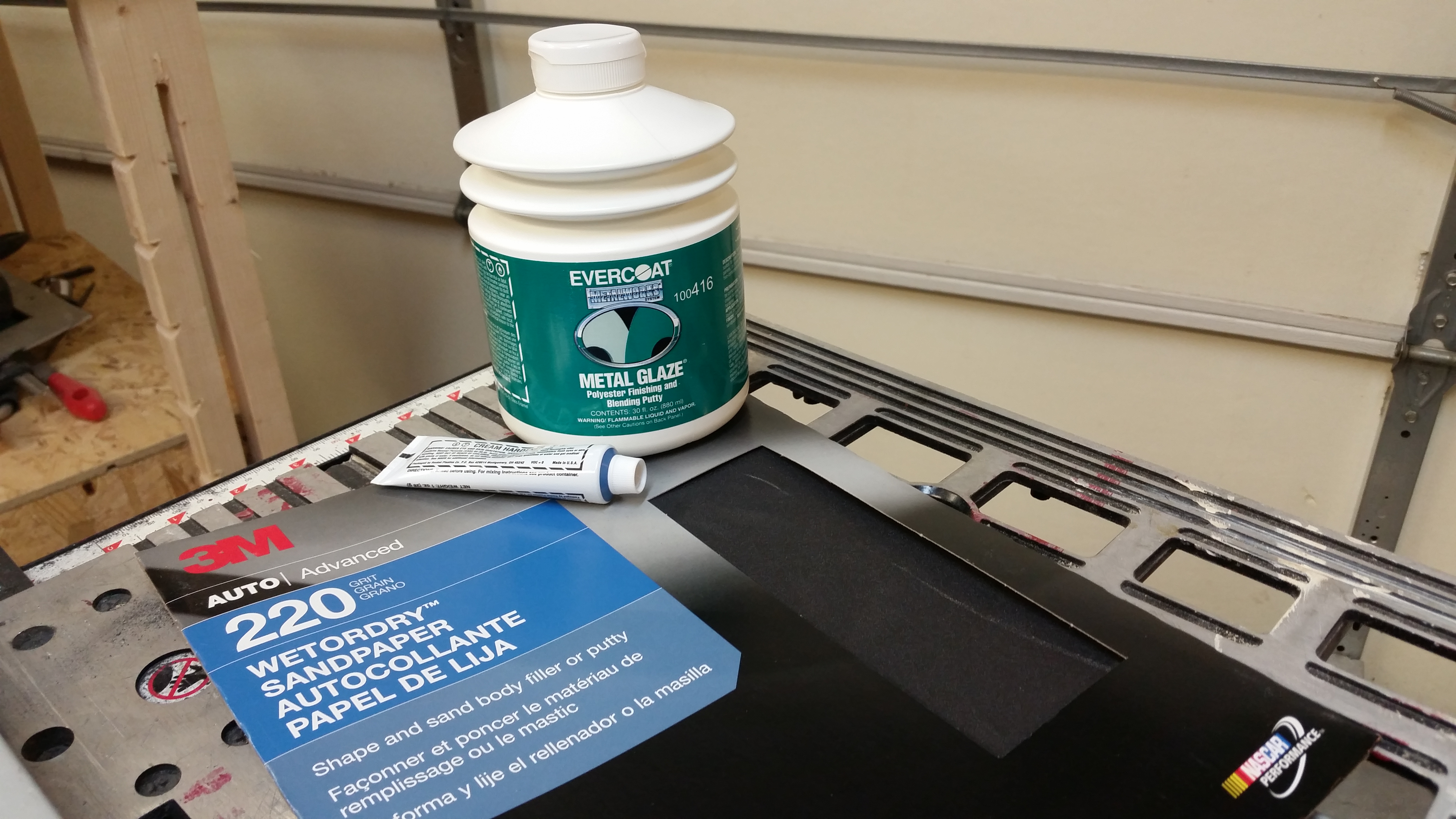
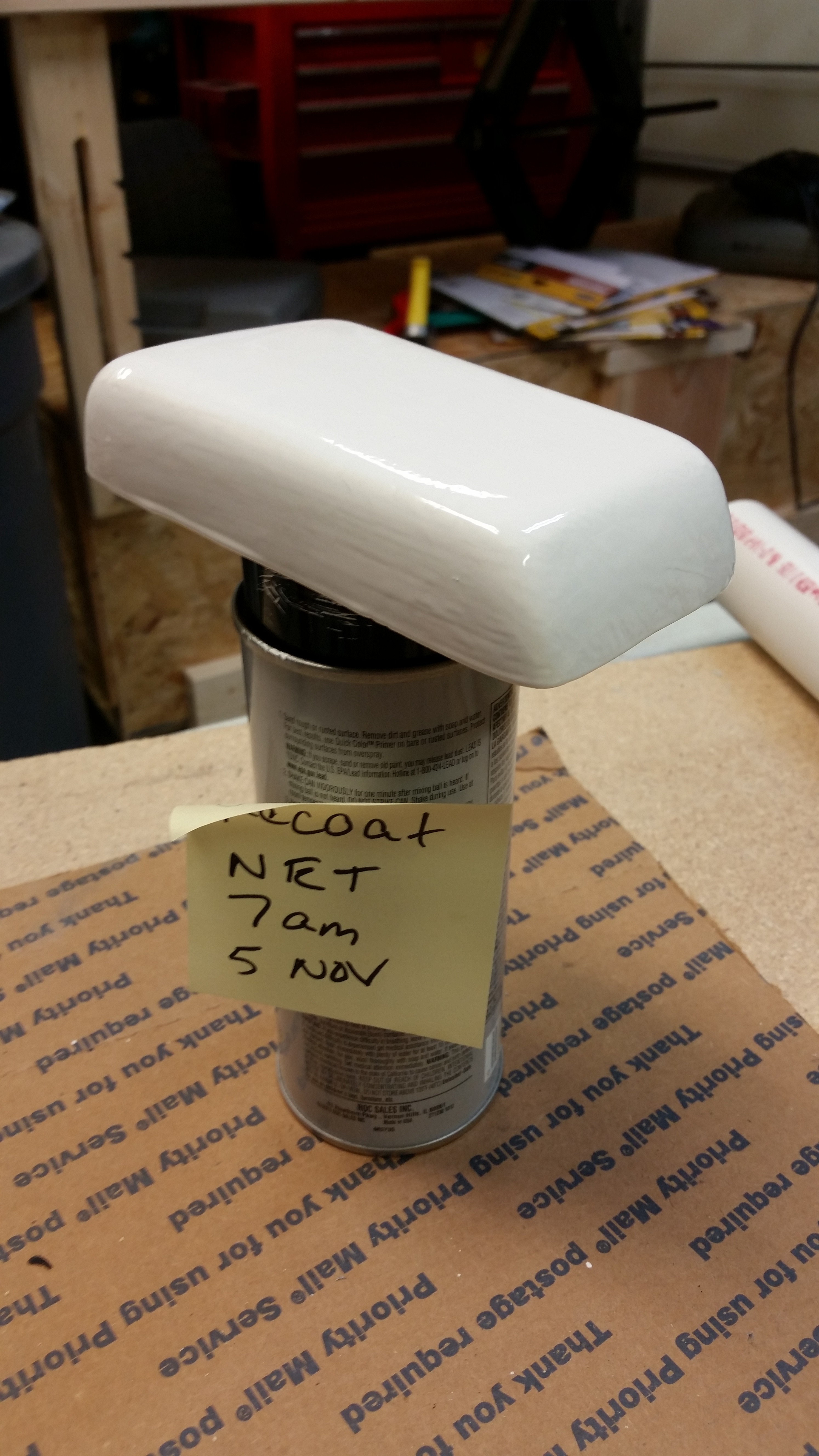
After a meeting I had in the office earlier today I ran over to Maryland to pick up a different brand of boat paint.  I’m going to do some tests and will report back on the entire plan later on.

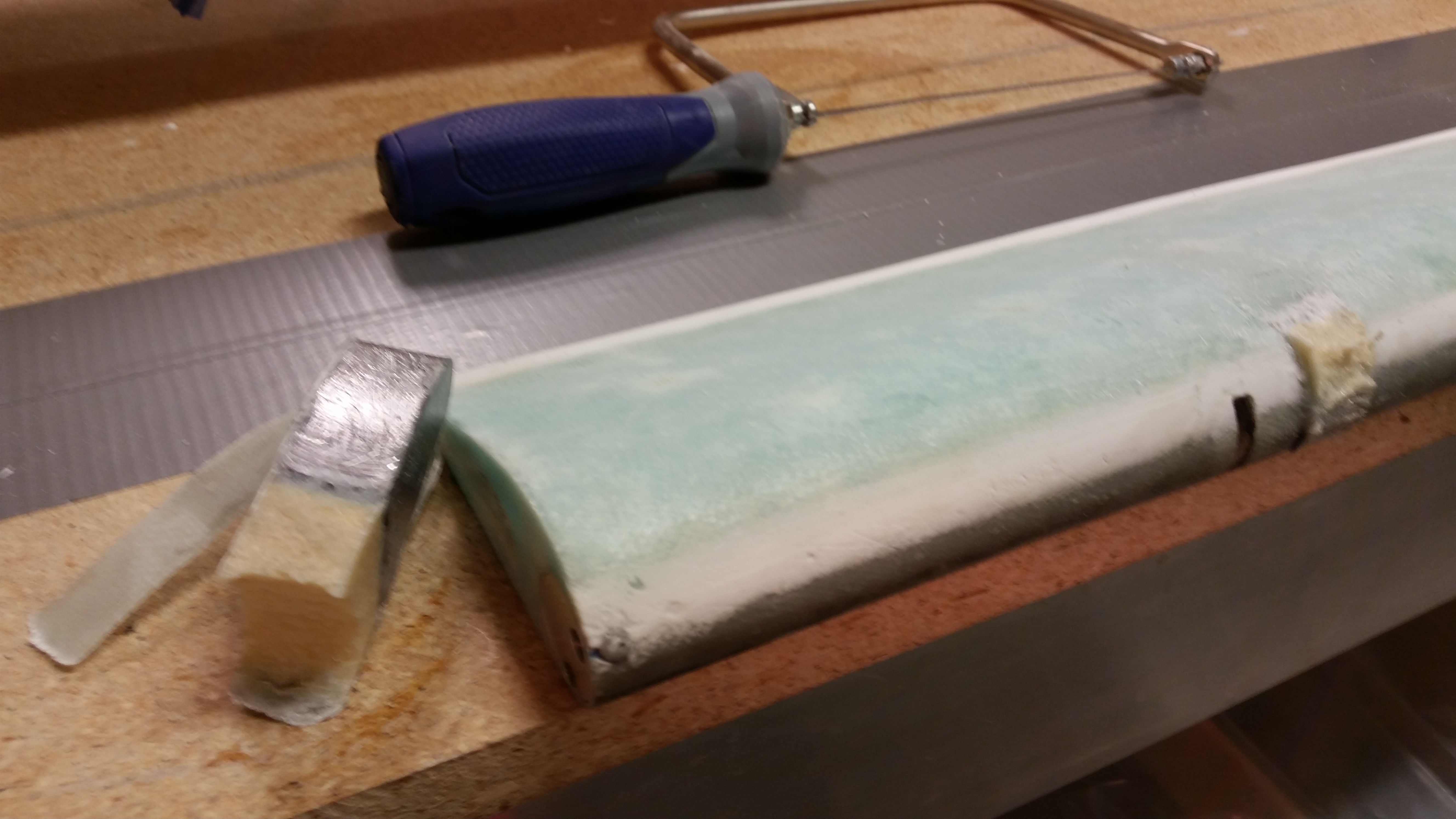
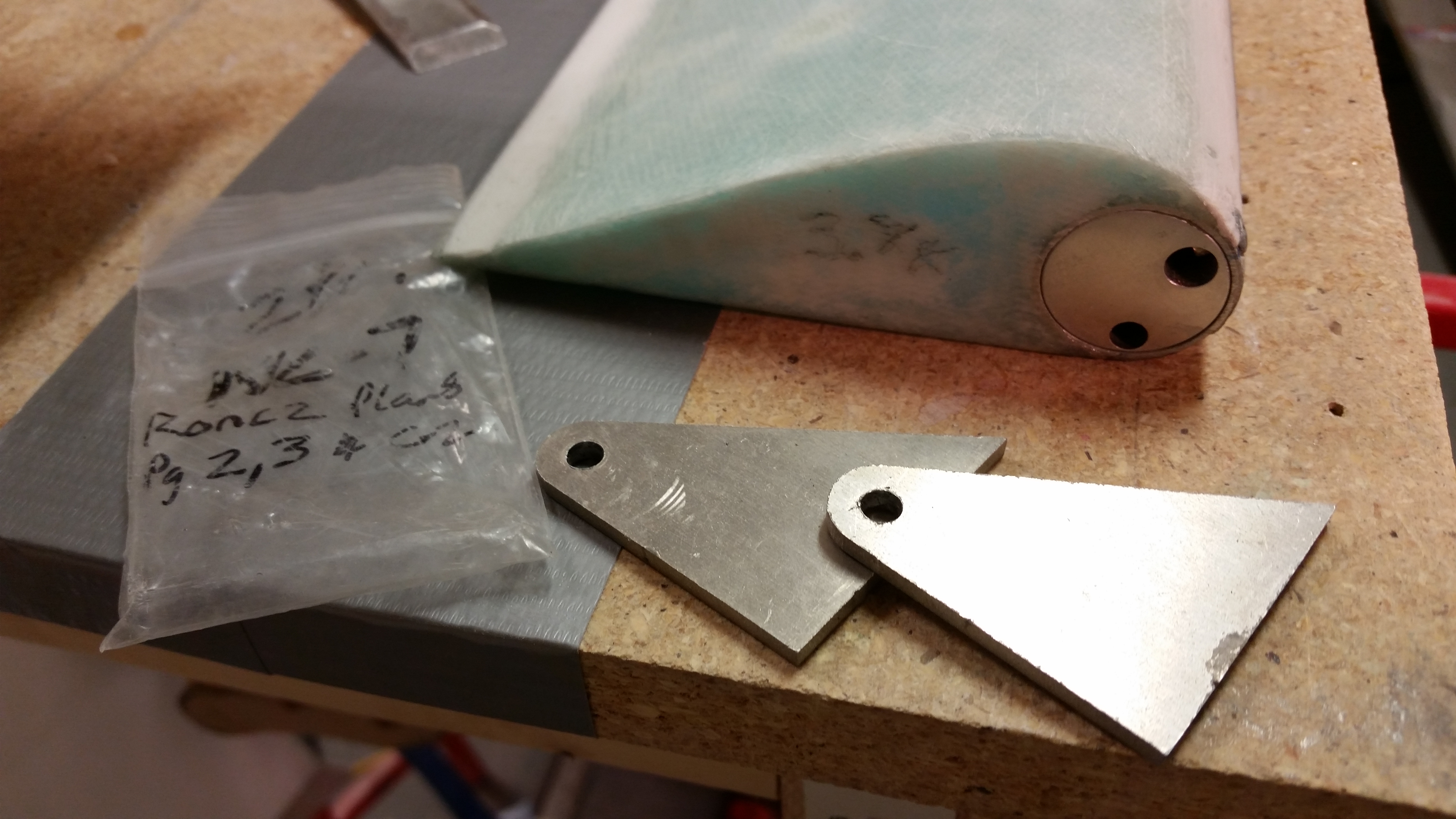
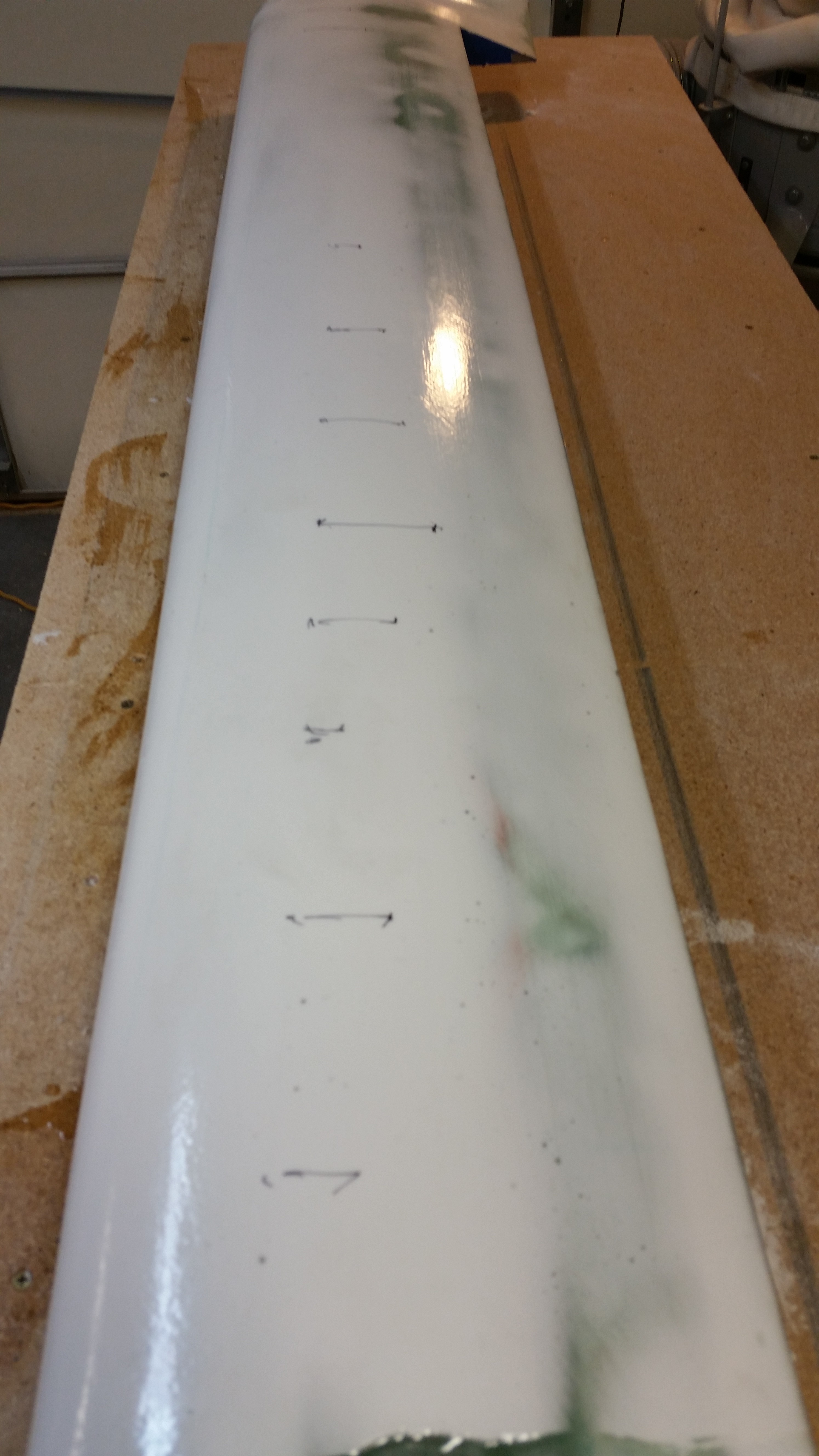
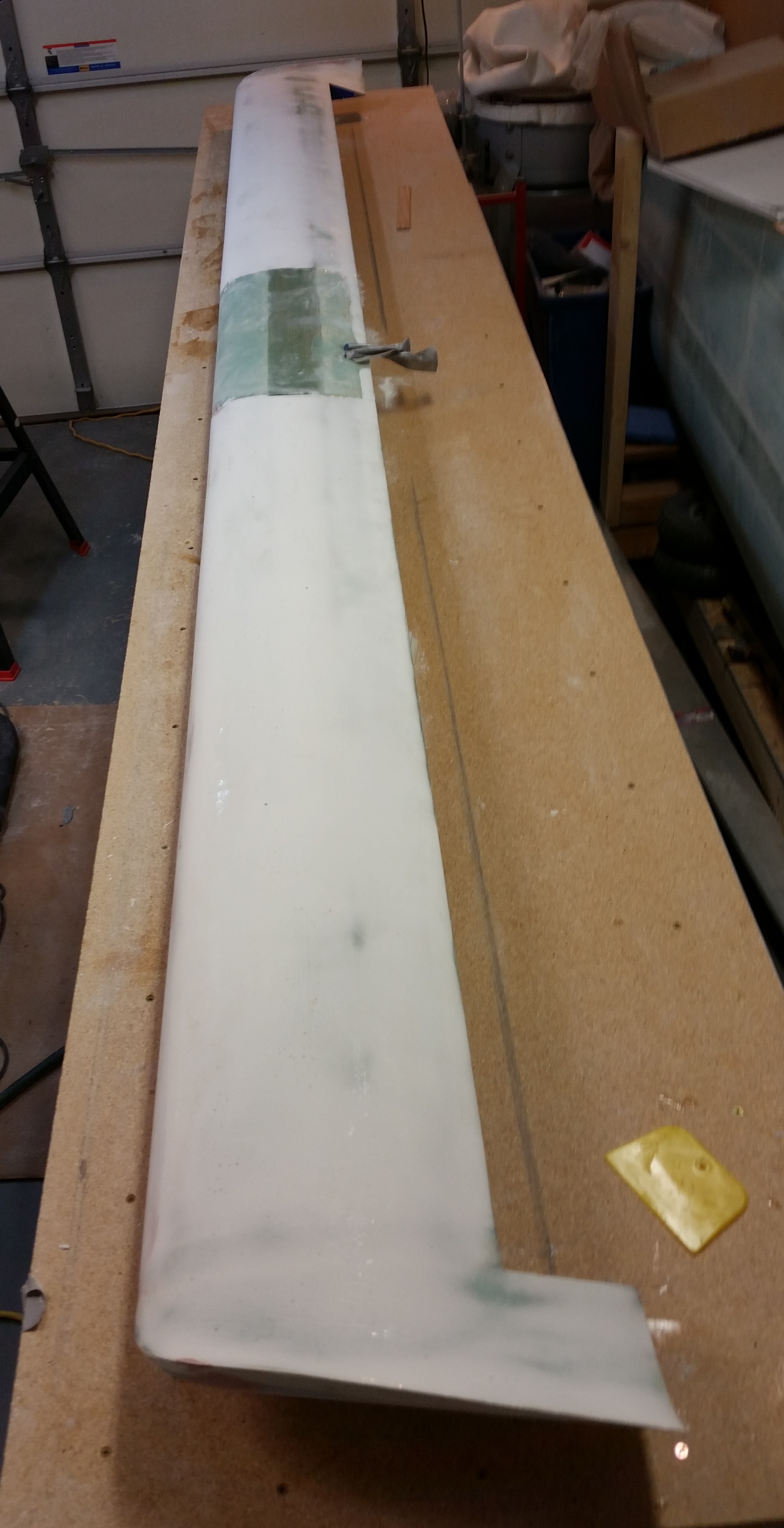
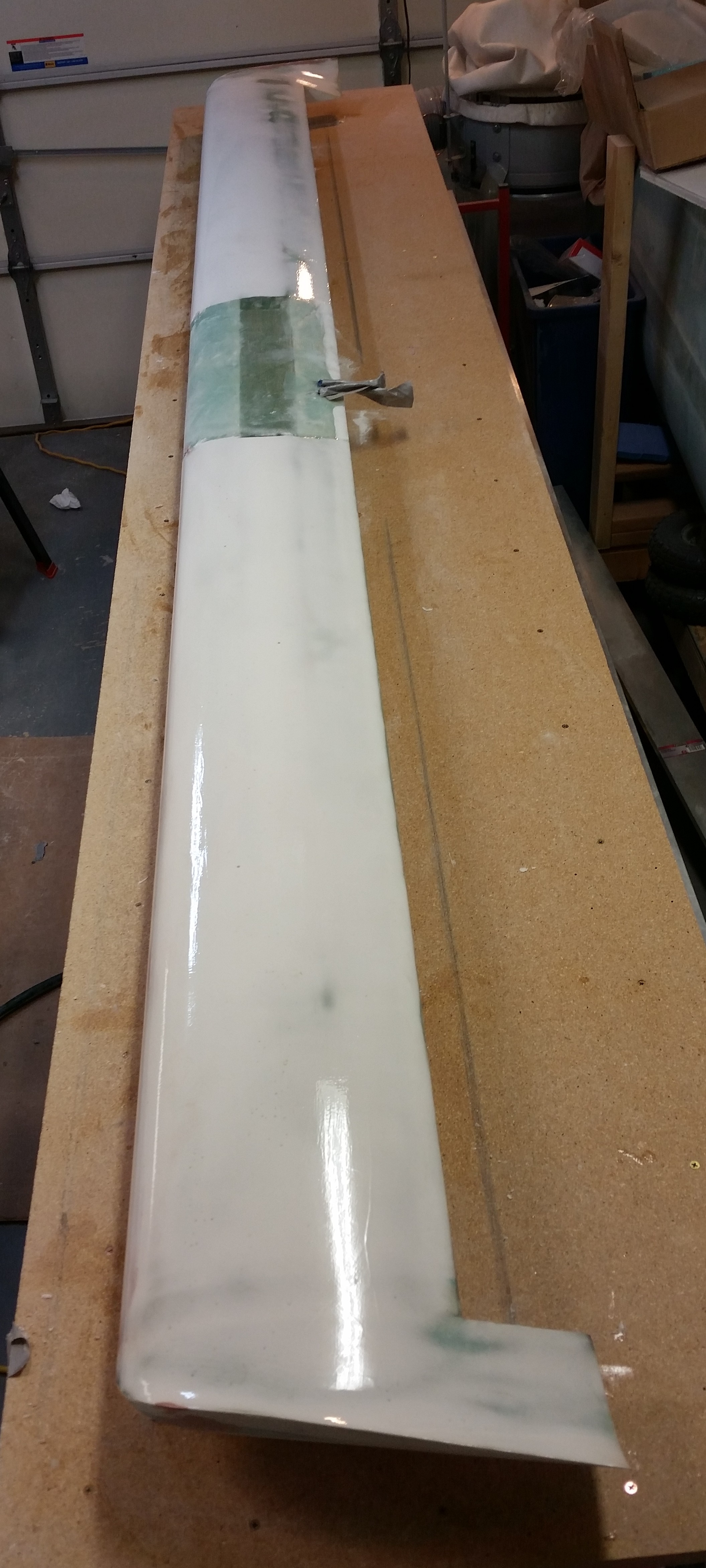
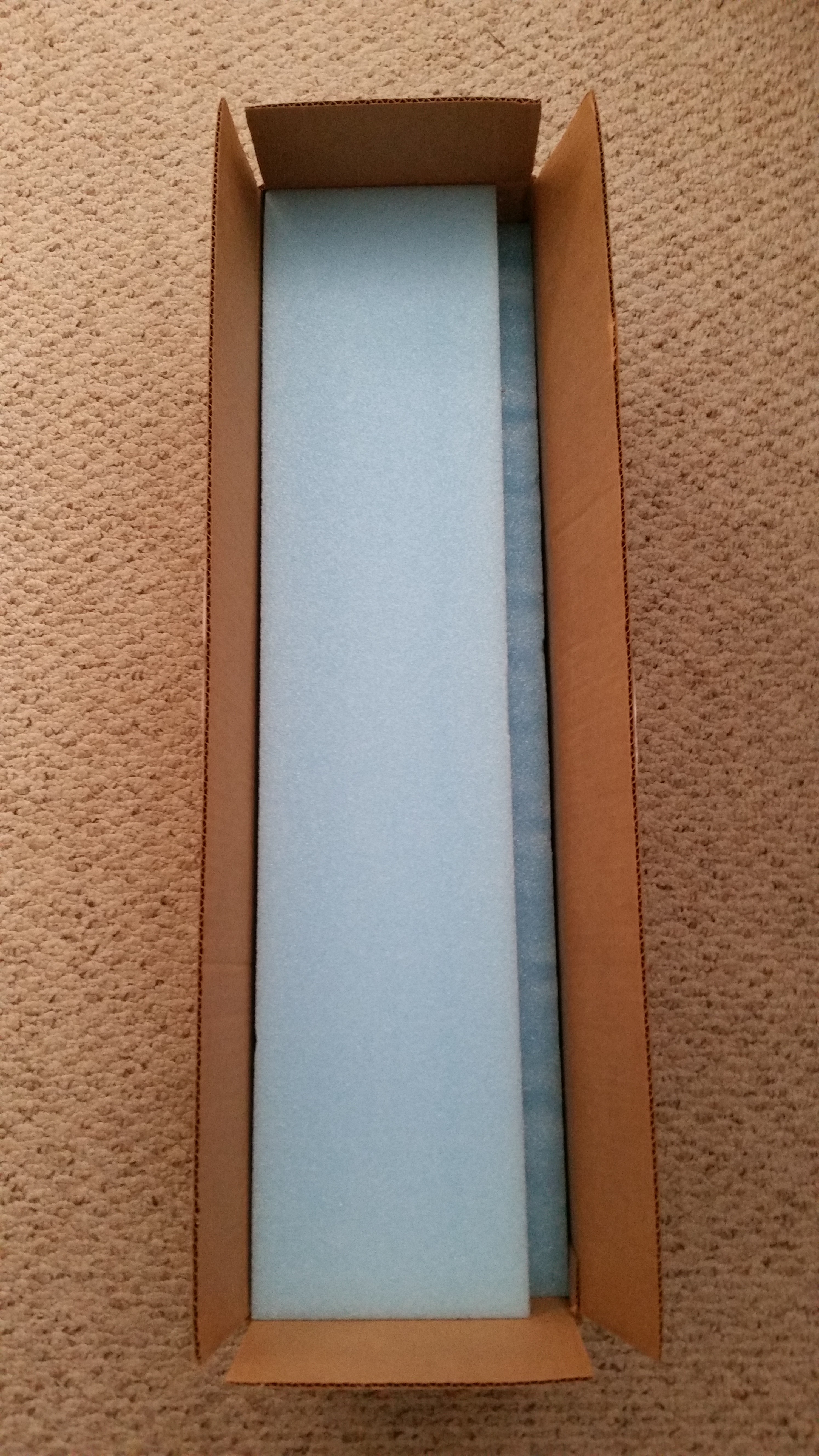
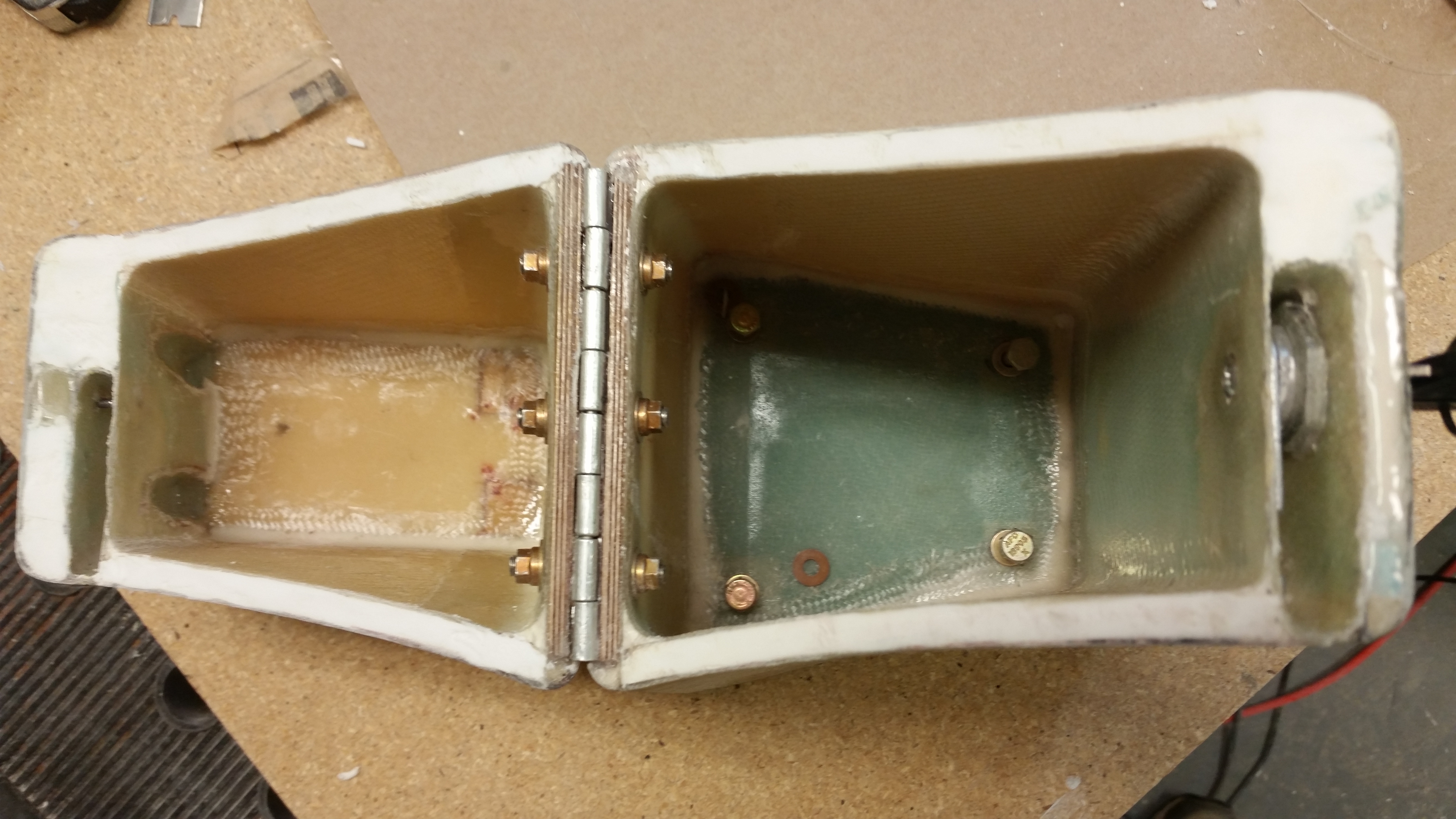
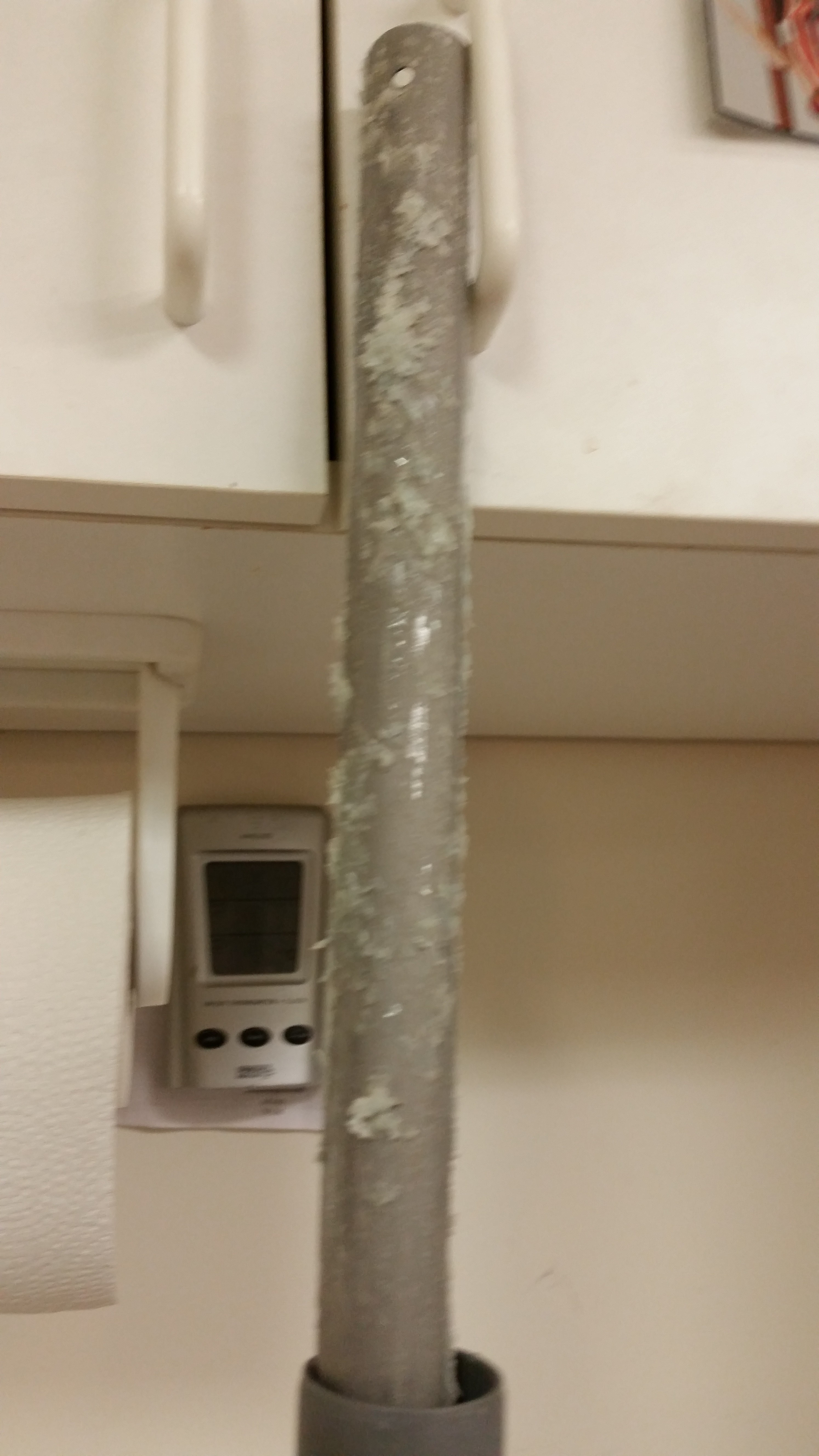
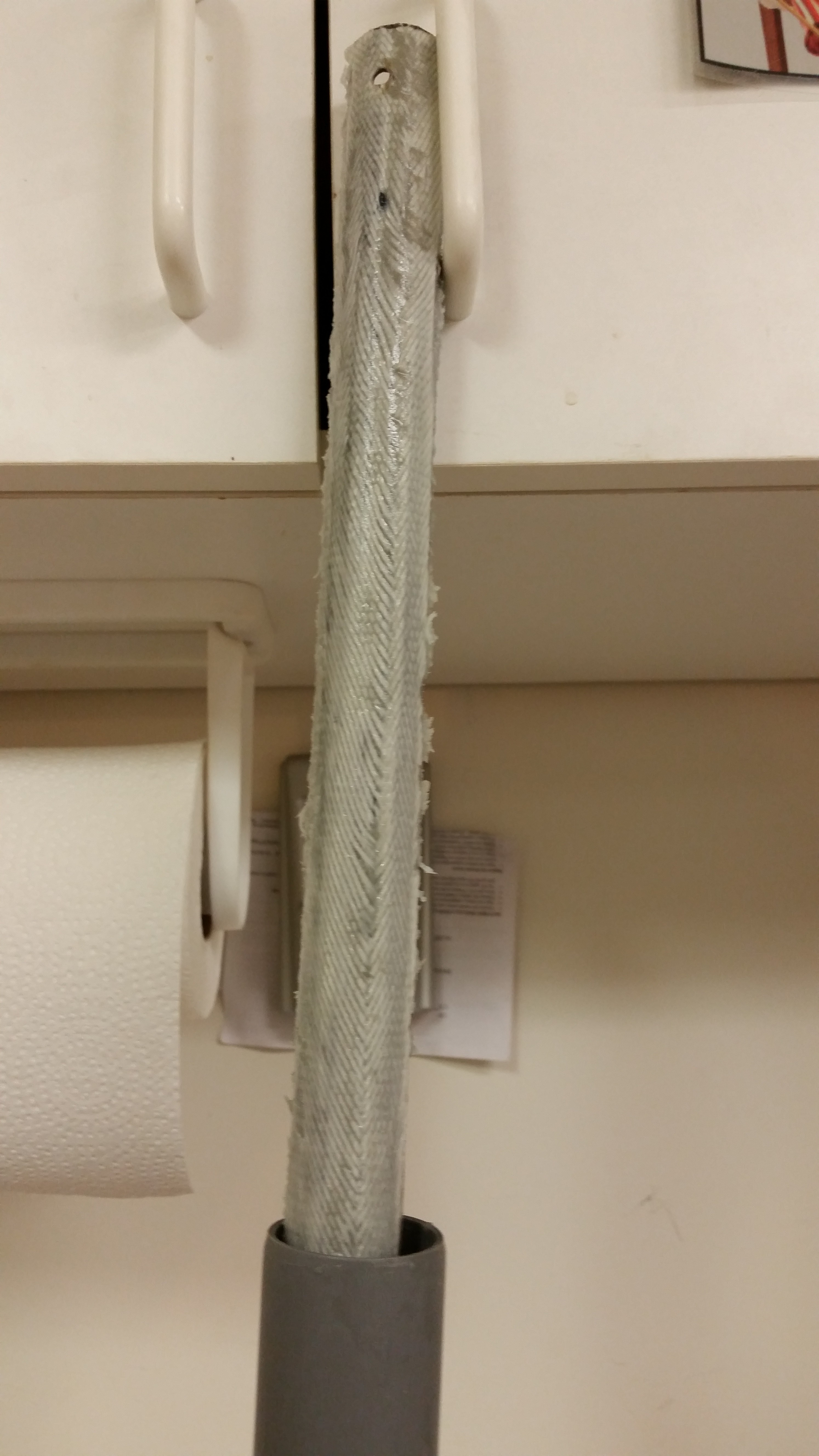
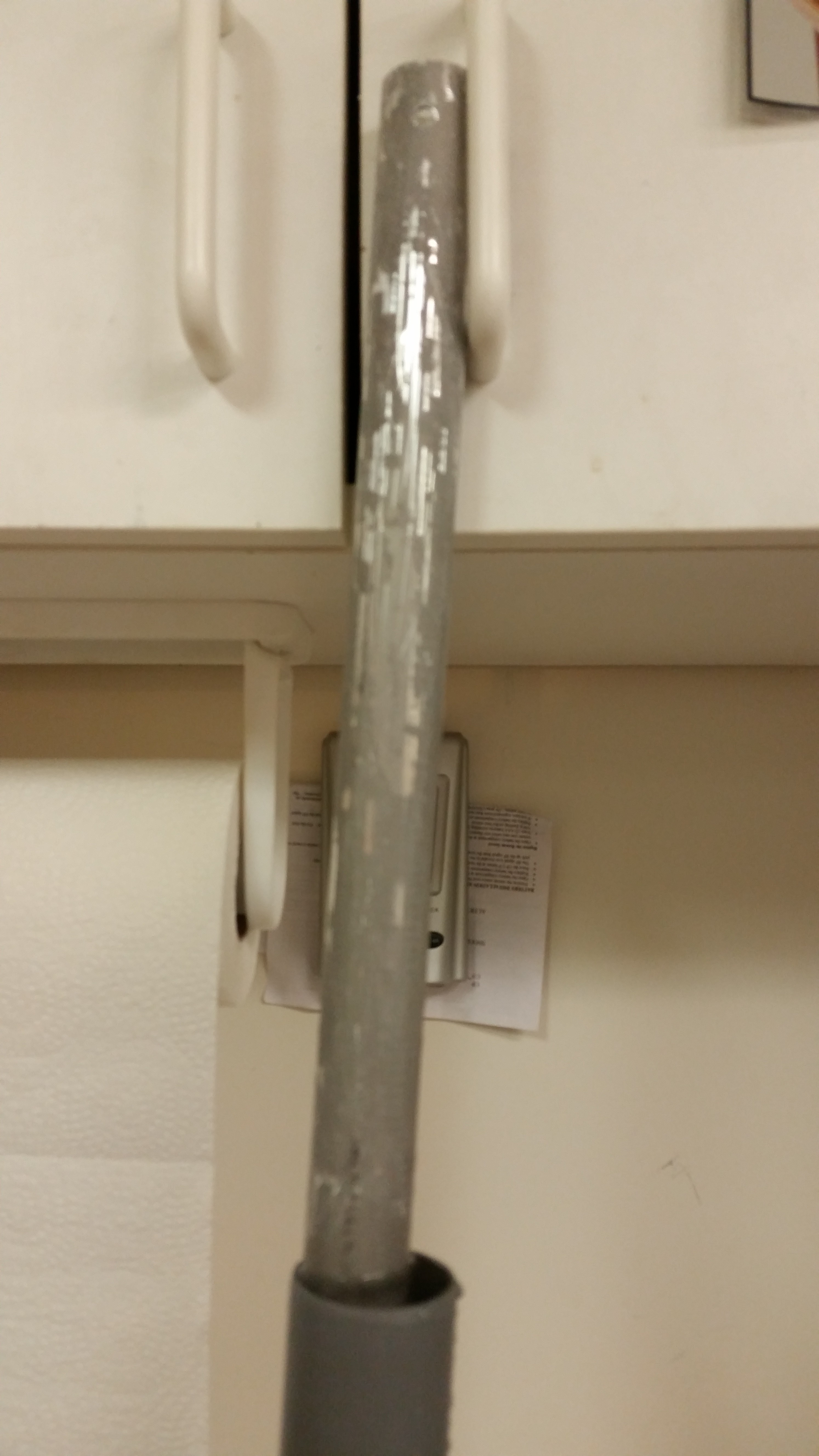
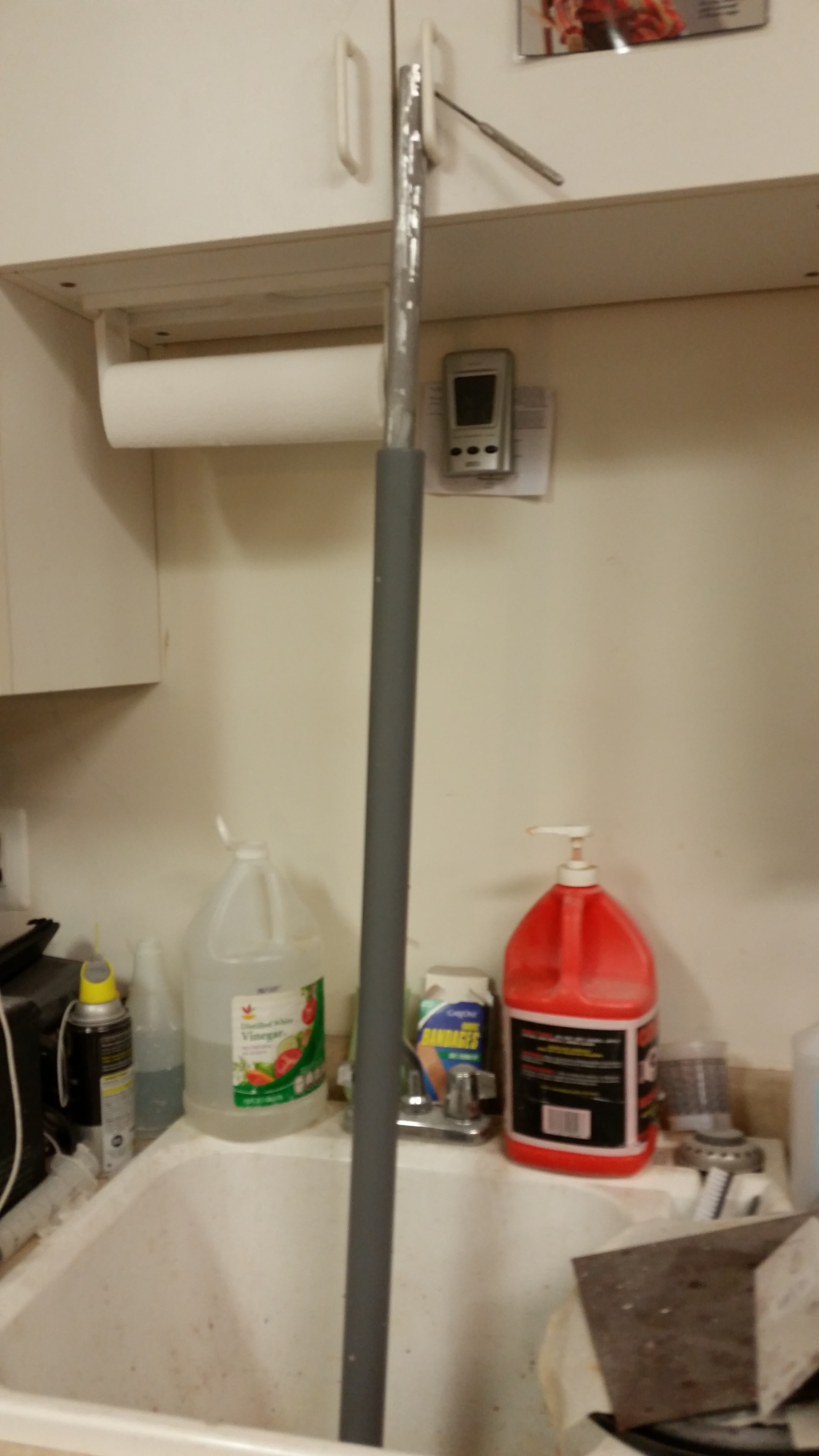
Upon returning home I took the elevator tube out of the PVC tube filled with white vinegar and flipped it over to get the untouched 25% into the vinegar.  I cleaned off the majority of gunk with paper towels, then grabbed my razor knife and started cleaning off the dead glass.  I got as far down as the second hinge hardpoint (NC2).

Elevator tube - foam gubersElevator tube - dead glassElevator tube - Initial clean

After getting as much of the soaked dead glass off the tube as possible, I set the elevator tube back into the PVC tube filled with vinegar to soak.

Elevator tube soaking

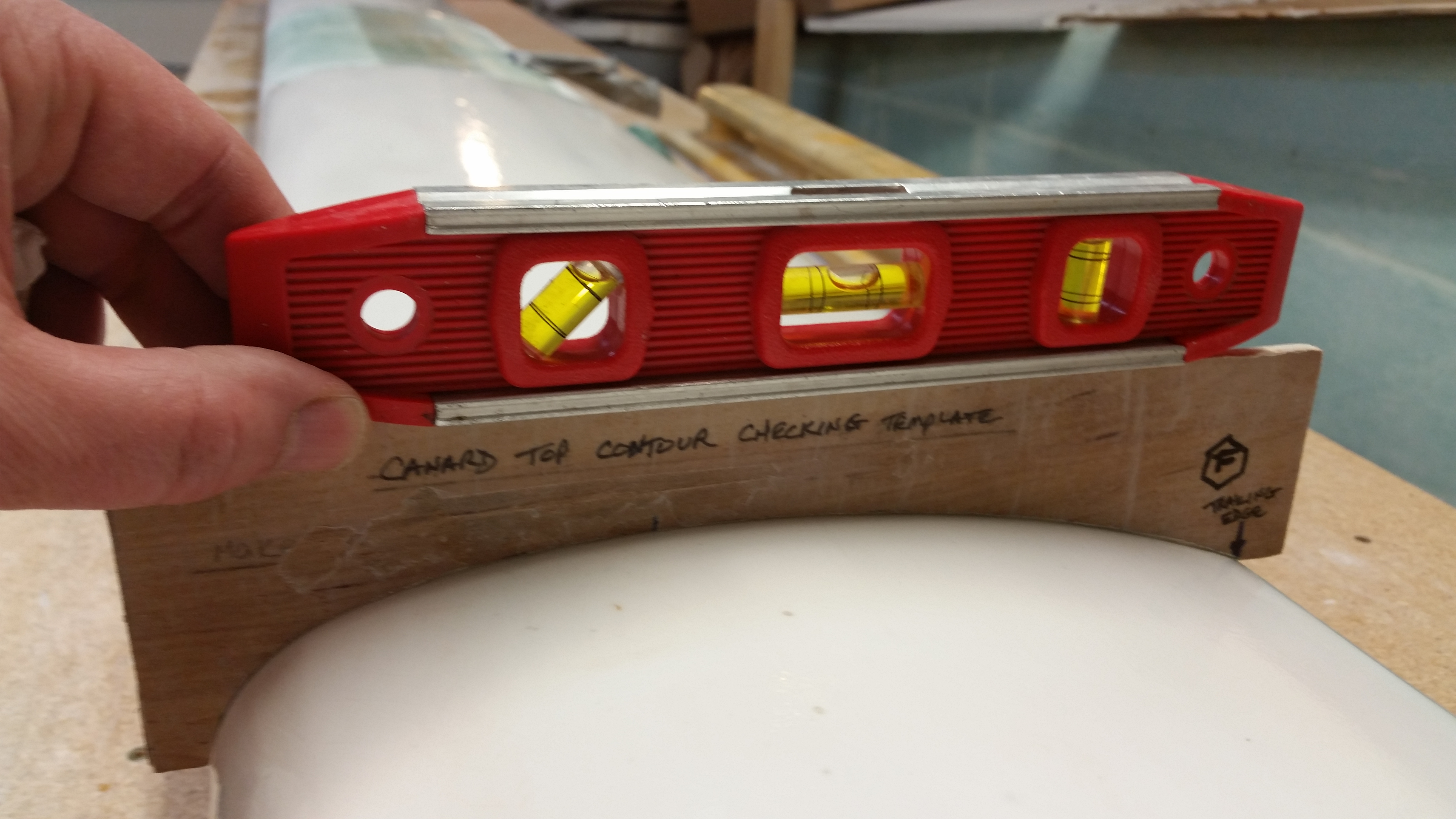
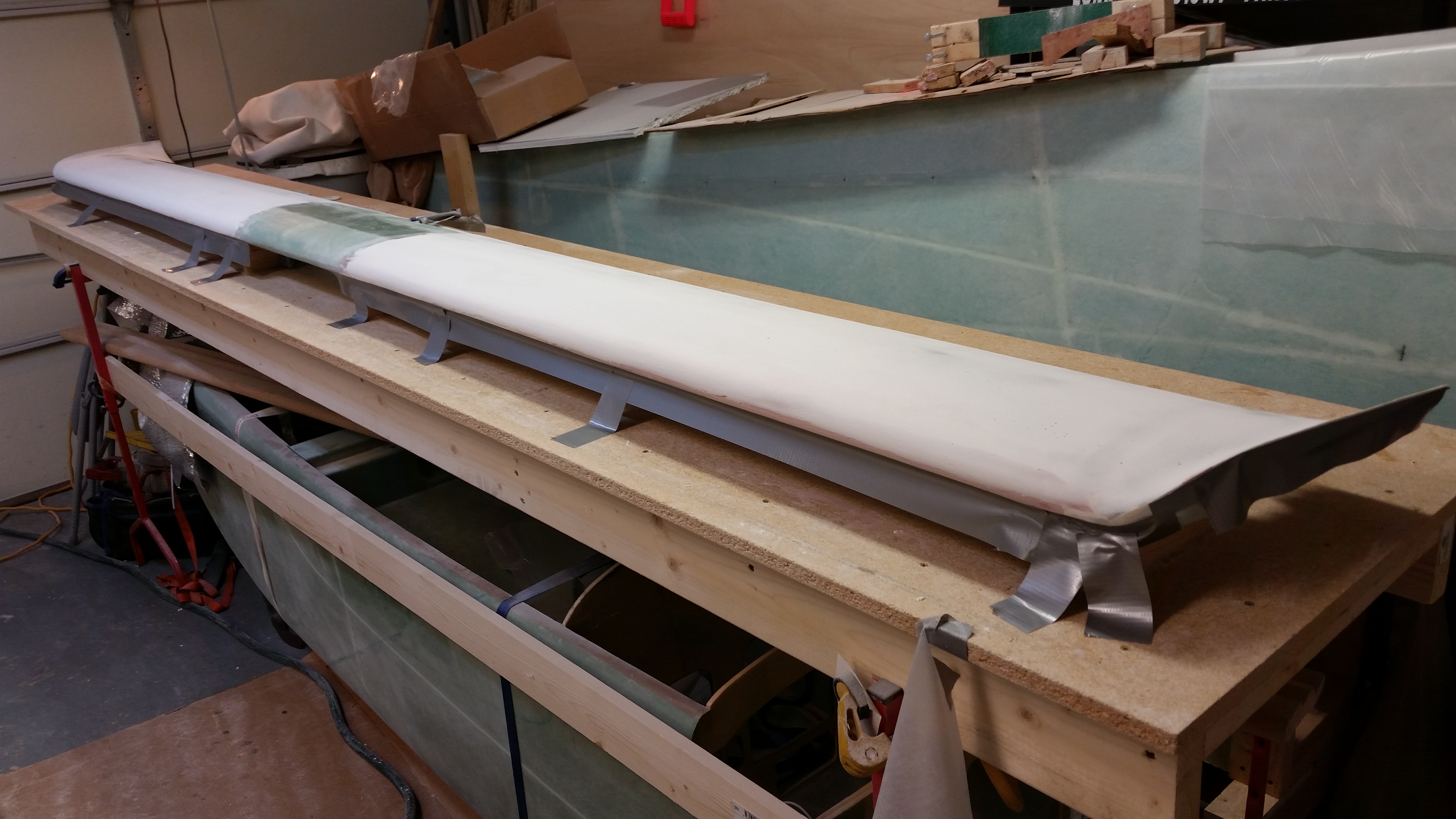
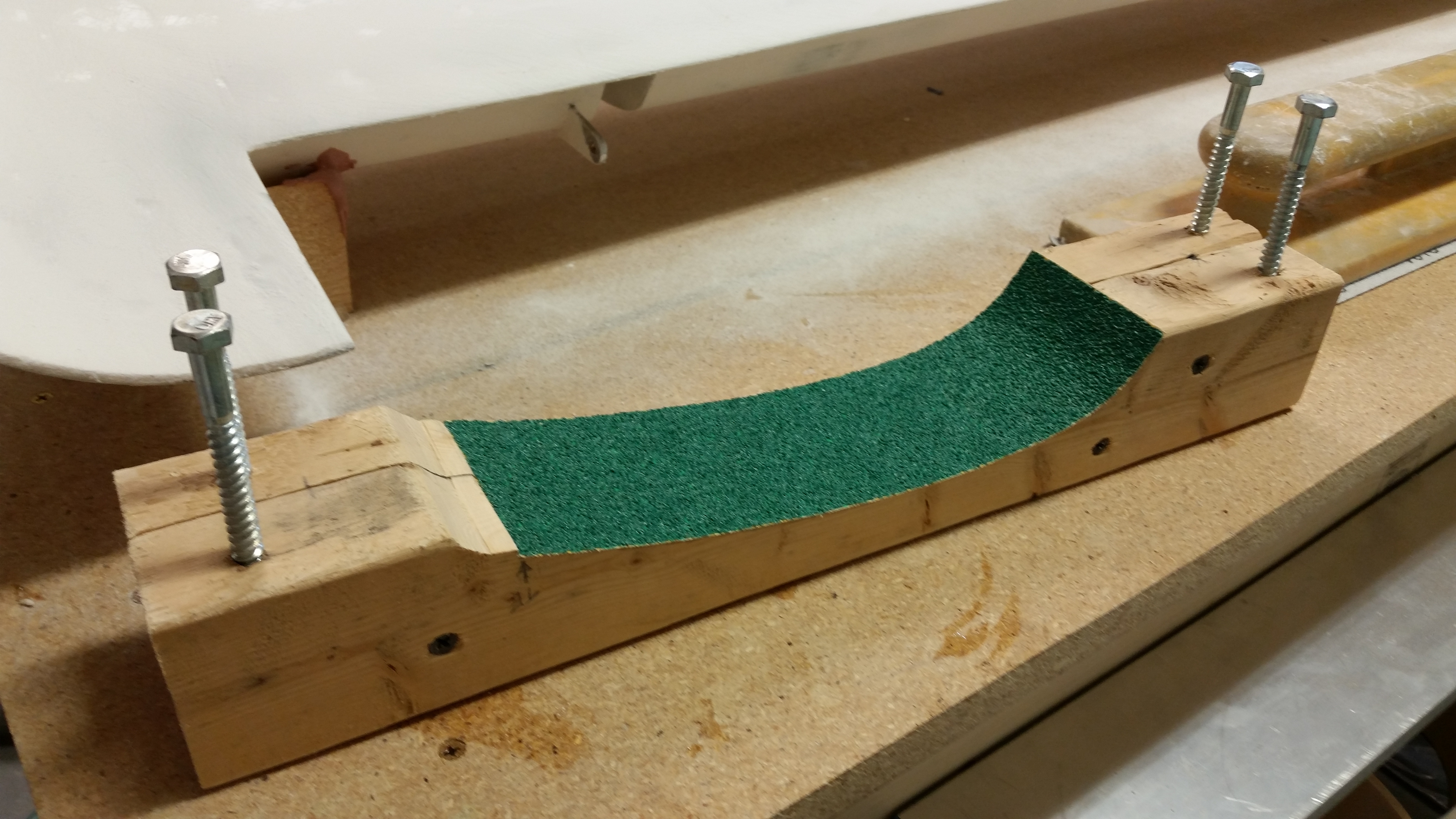
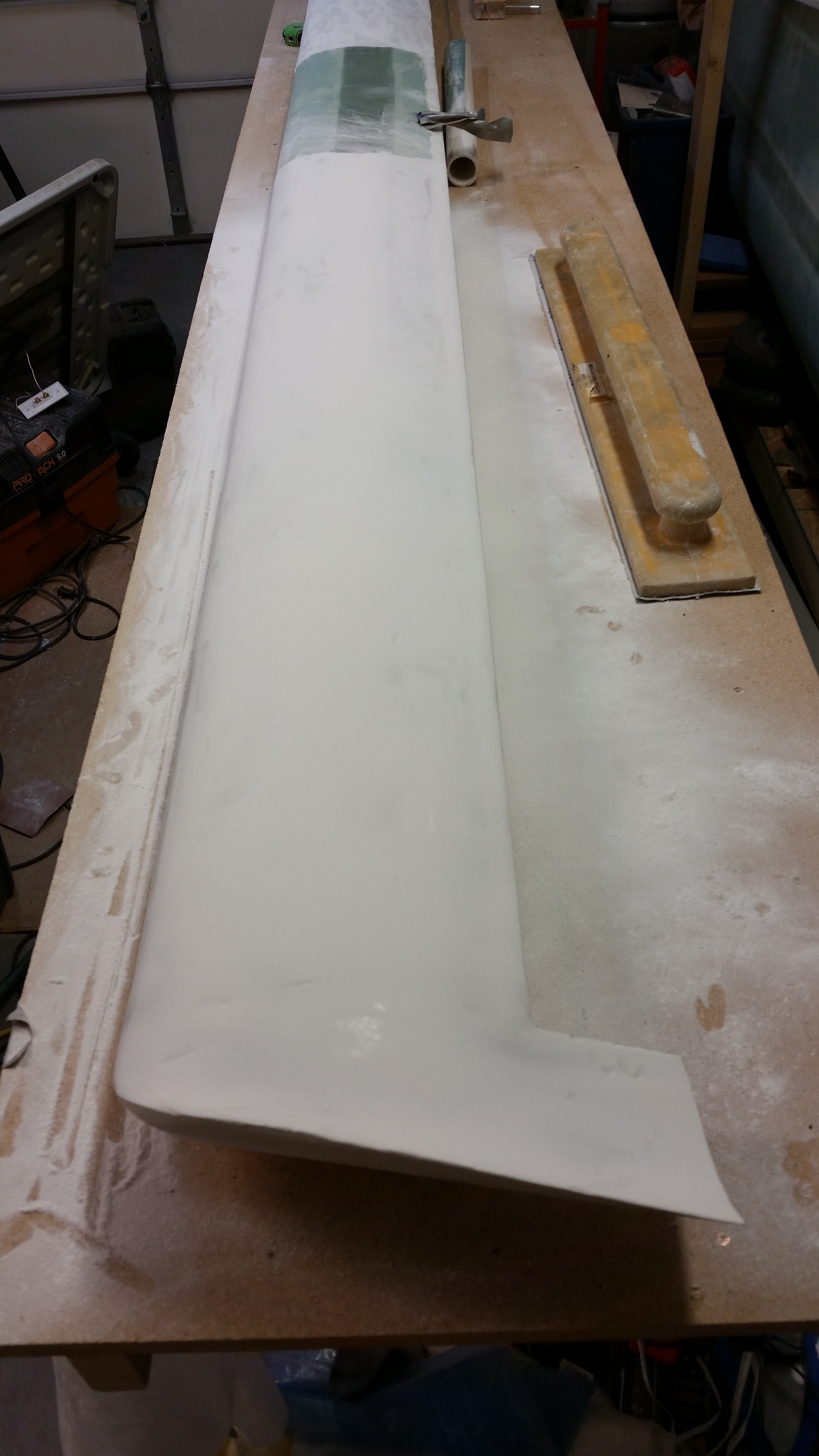
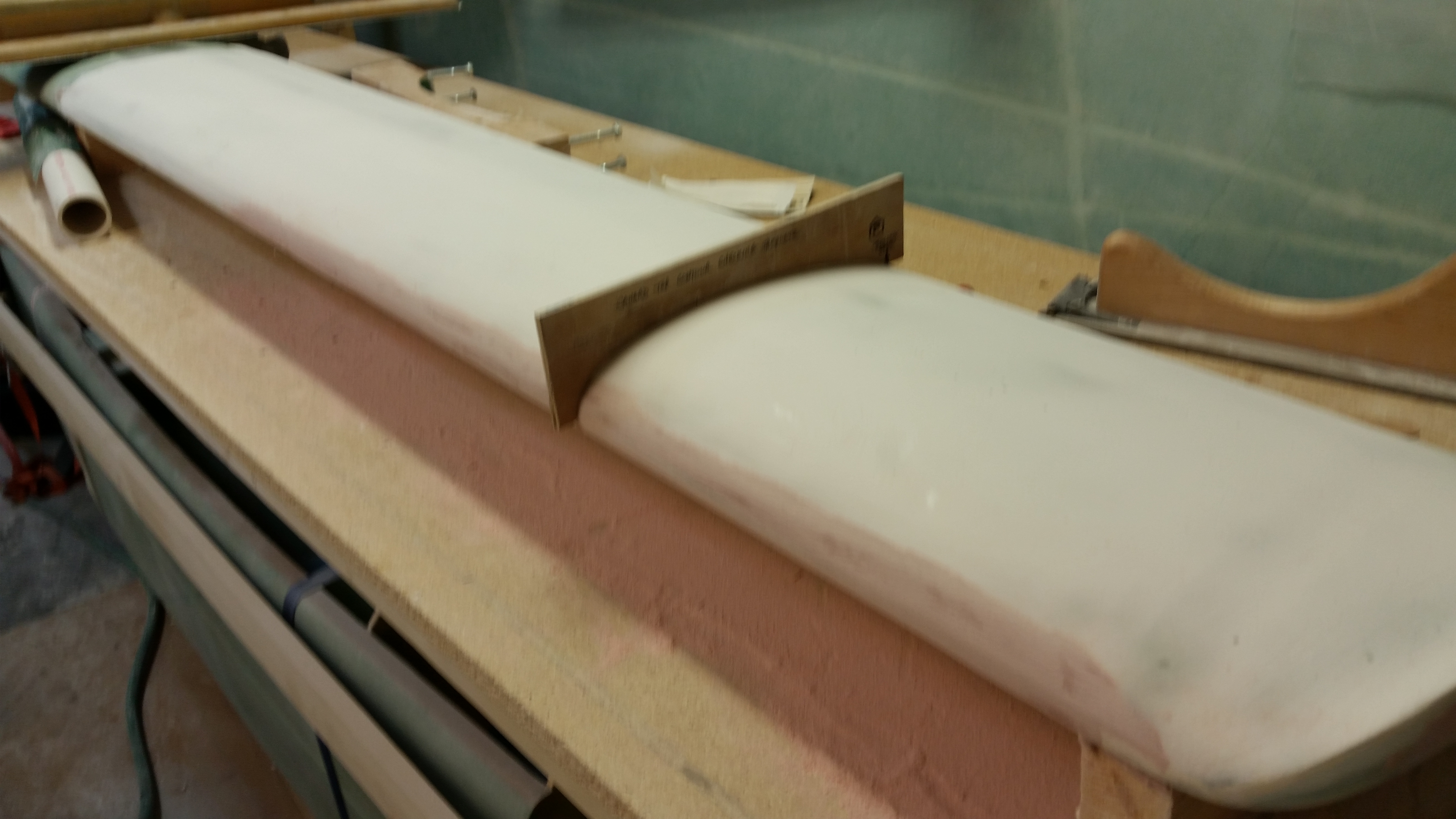
After I put the elevator tube back in the vinegar cleaning solution, I then sanded the canard surface starting with 80 grit on the long board, and then switched to 120 grit on the long board as well.  I then switched to 150 grit paper and hand sanded each swoosh tip.

I was still getting a fair amount of residue on the sandpaper and had to clean it off the paper at regular intervals.  After going through another few sheets of very expensive long board sandpaper (although tonight was much better than last night as far as residue buildup), I decided to wait until tomorrow to finish sanding the top of the canard after it’s cured just a bit more.

In addition, I’m going to hit the canard with another couple coats of primer of the new boat paint.  I can tell already that this new primer is much more high build than my current primer, and of course you always need a good base of primer preferably of the same brand.  In light of this, I really want to get this primer sanded down to where the canard shape is as close to final as possible, and then smoothed out even more once the new primer is applied.

Sanded primer - Round 2 of 3

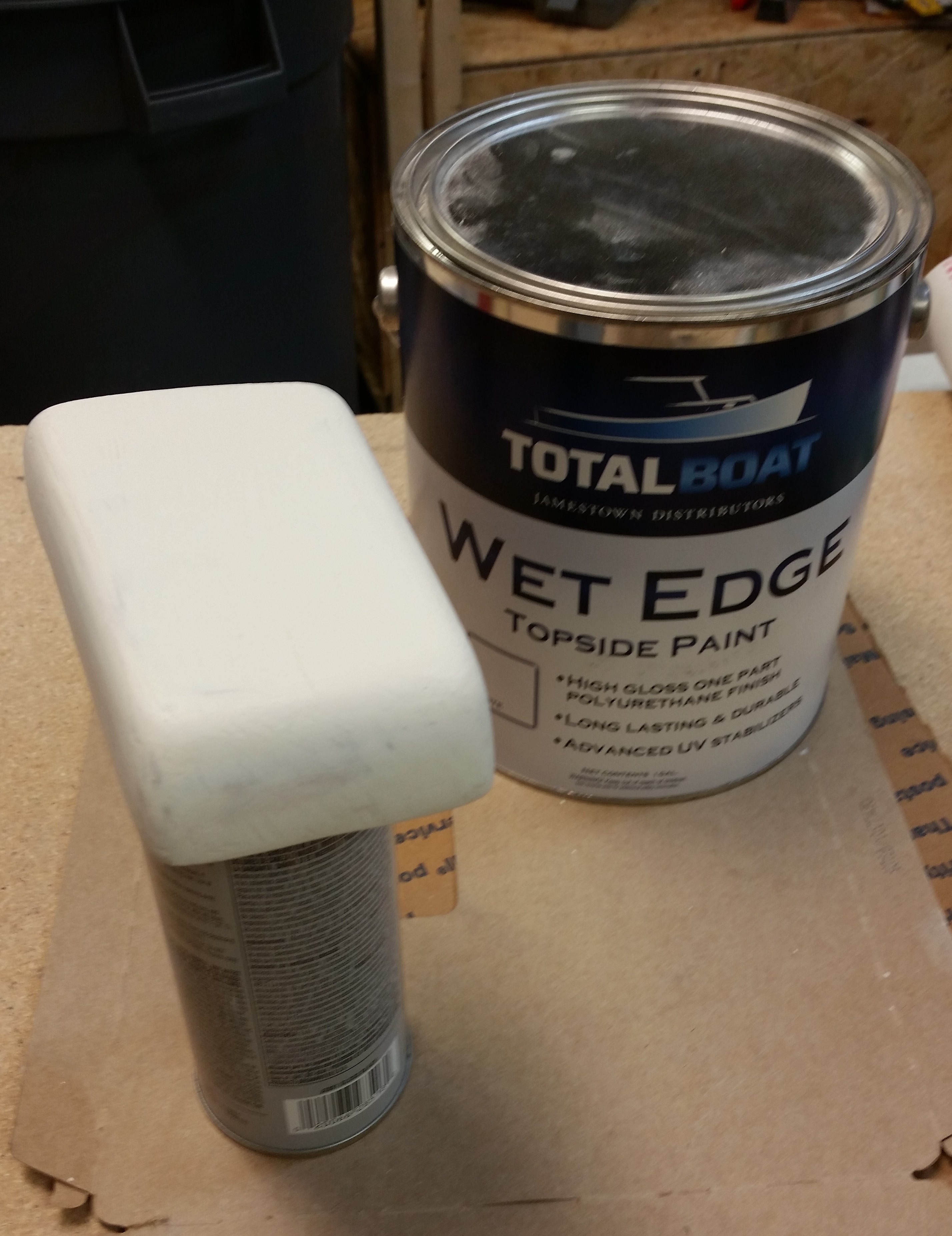
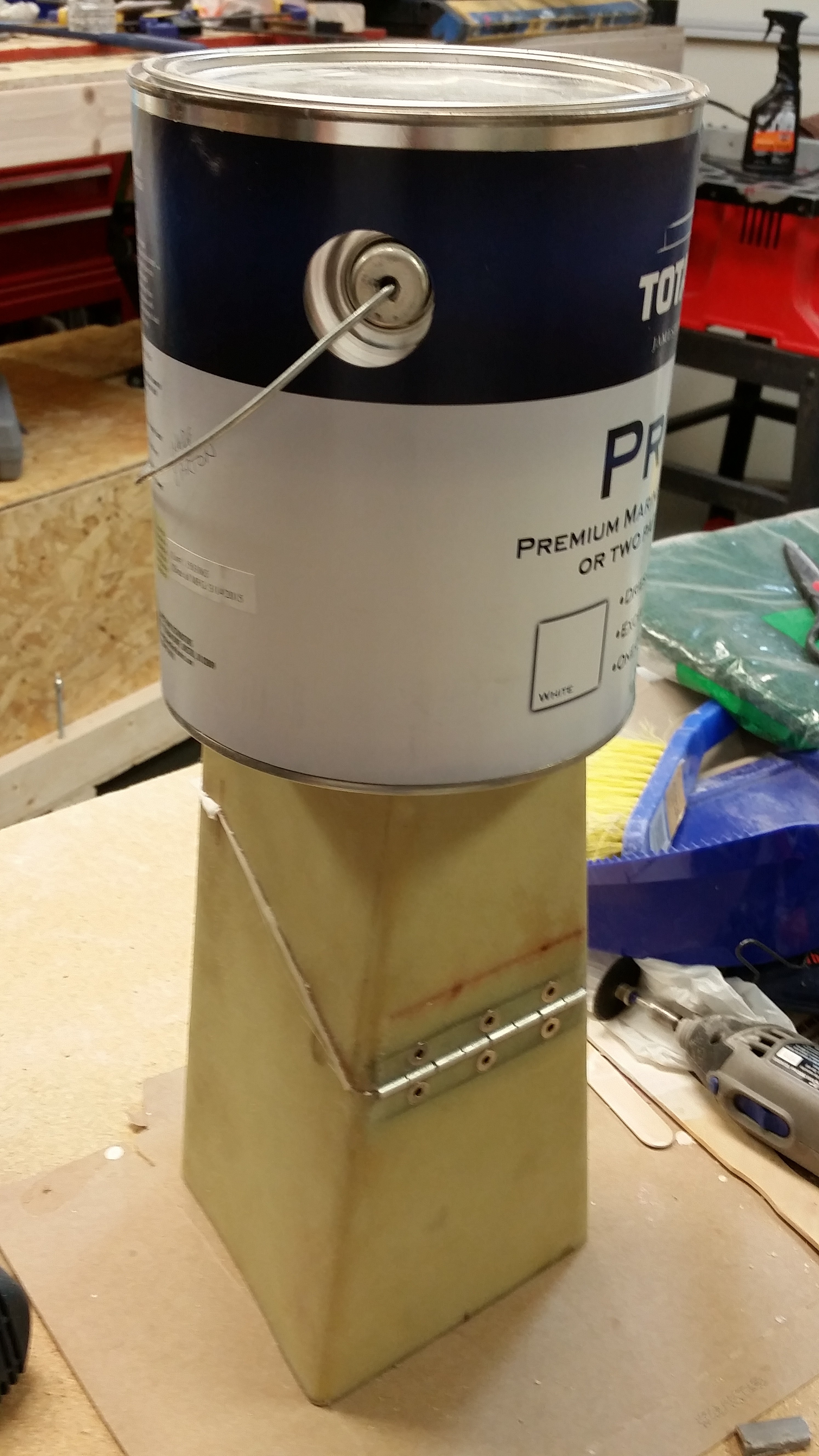
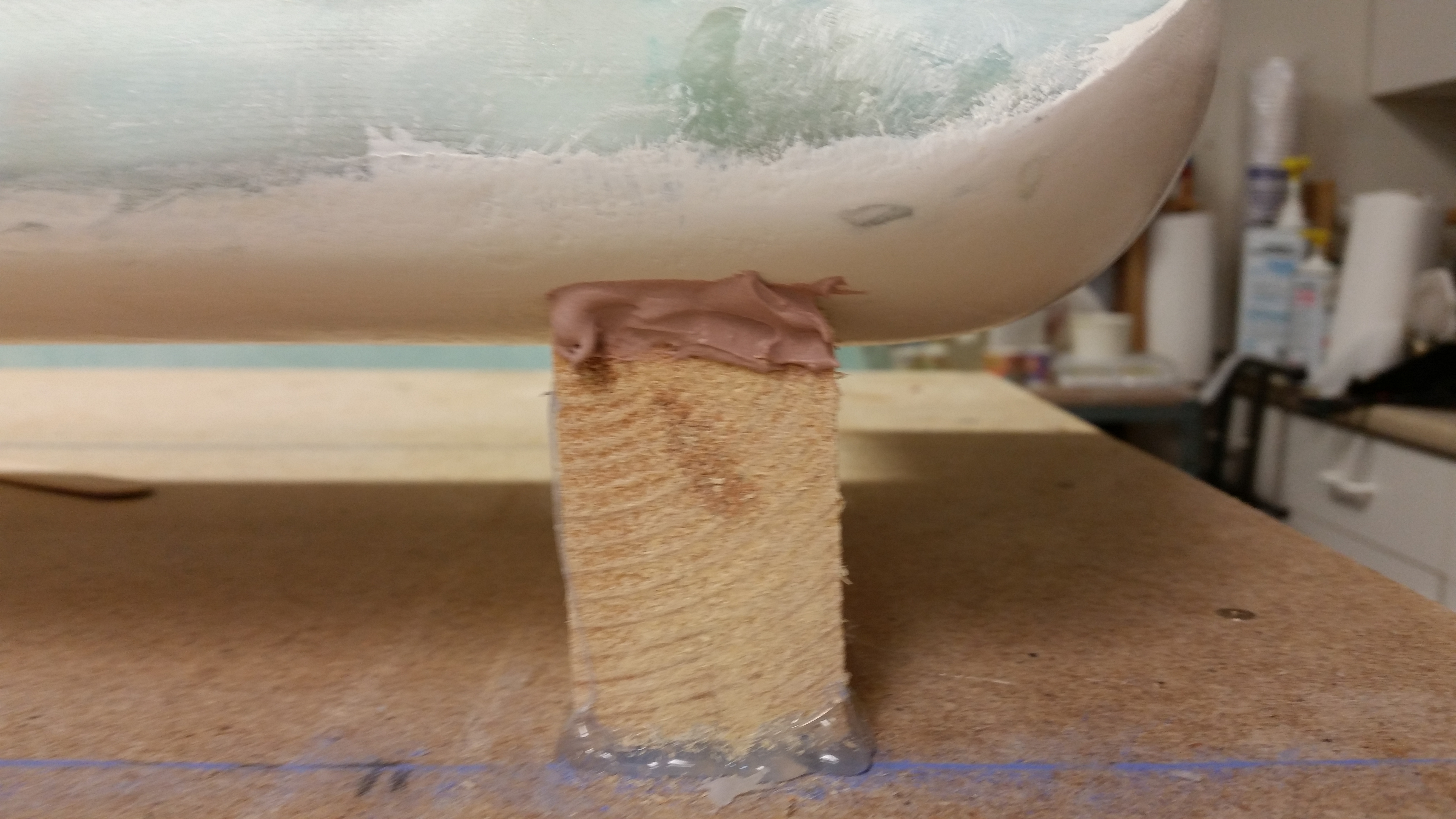
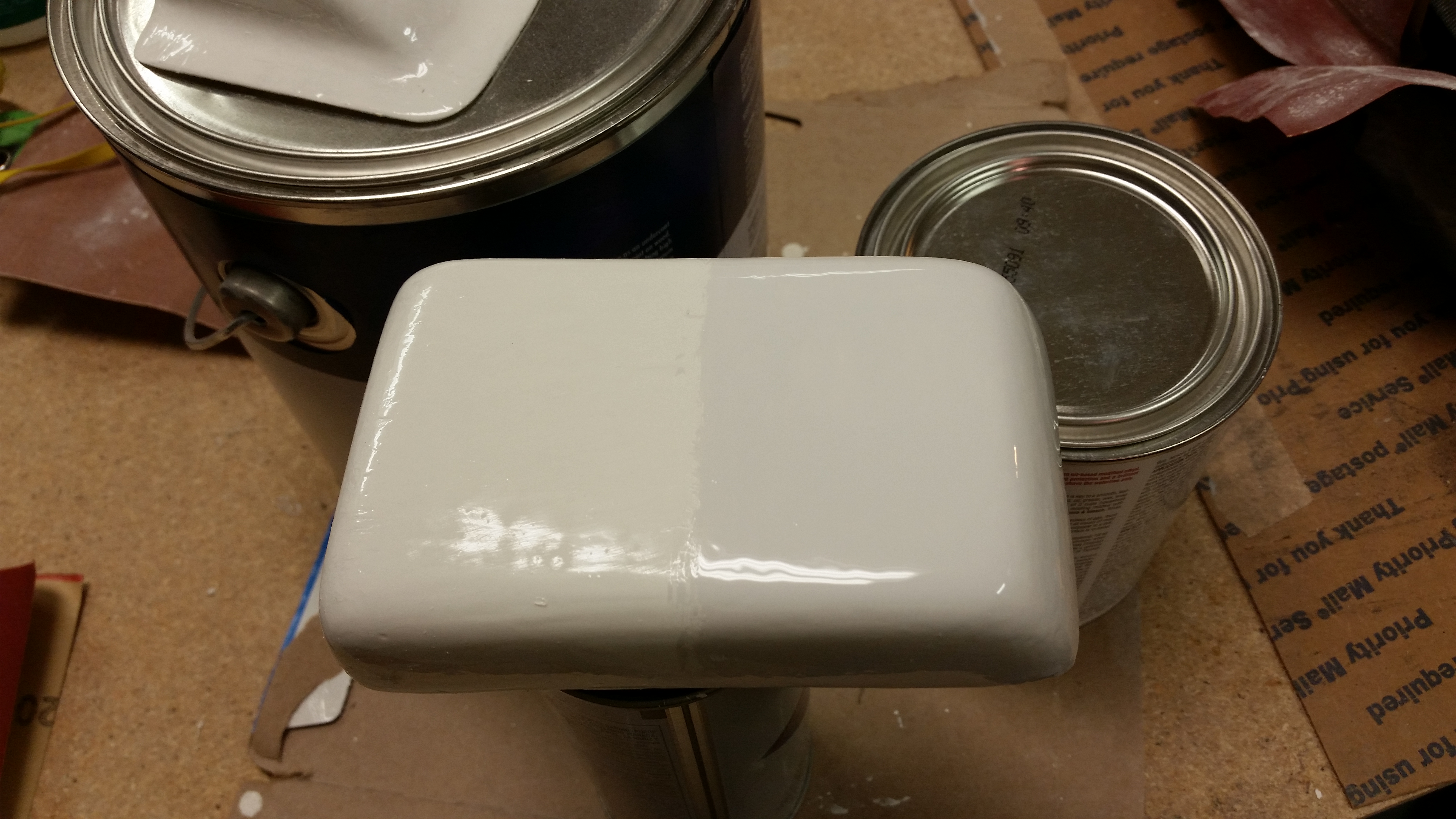
I then broke out the new paint to try it out.  As I said before as I was looking at the actual color of the white boat paint I had ordered before, in contrast with the white label on the gallon can and a standard white piece of paper, it clearly looked off white.  To compare and contrast the new paint I sanded down half of the headrest GPS antenna cover with 220 grit paper, and then painted it with the new paint.  I have to say that A) the new boat paint went on much easier and laid down much better than the old boat paint, and B) the new paint seems to have more of a “blue” hue vs a “yellow” hue, as you can see below. The bottom line is that the new paint is simply whiter, in my opinion.

New paint

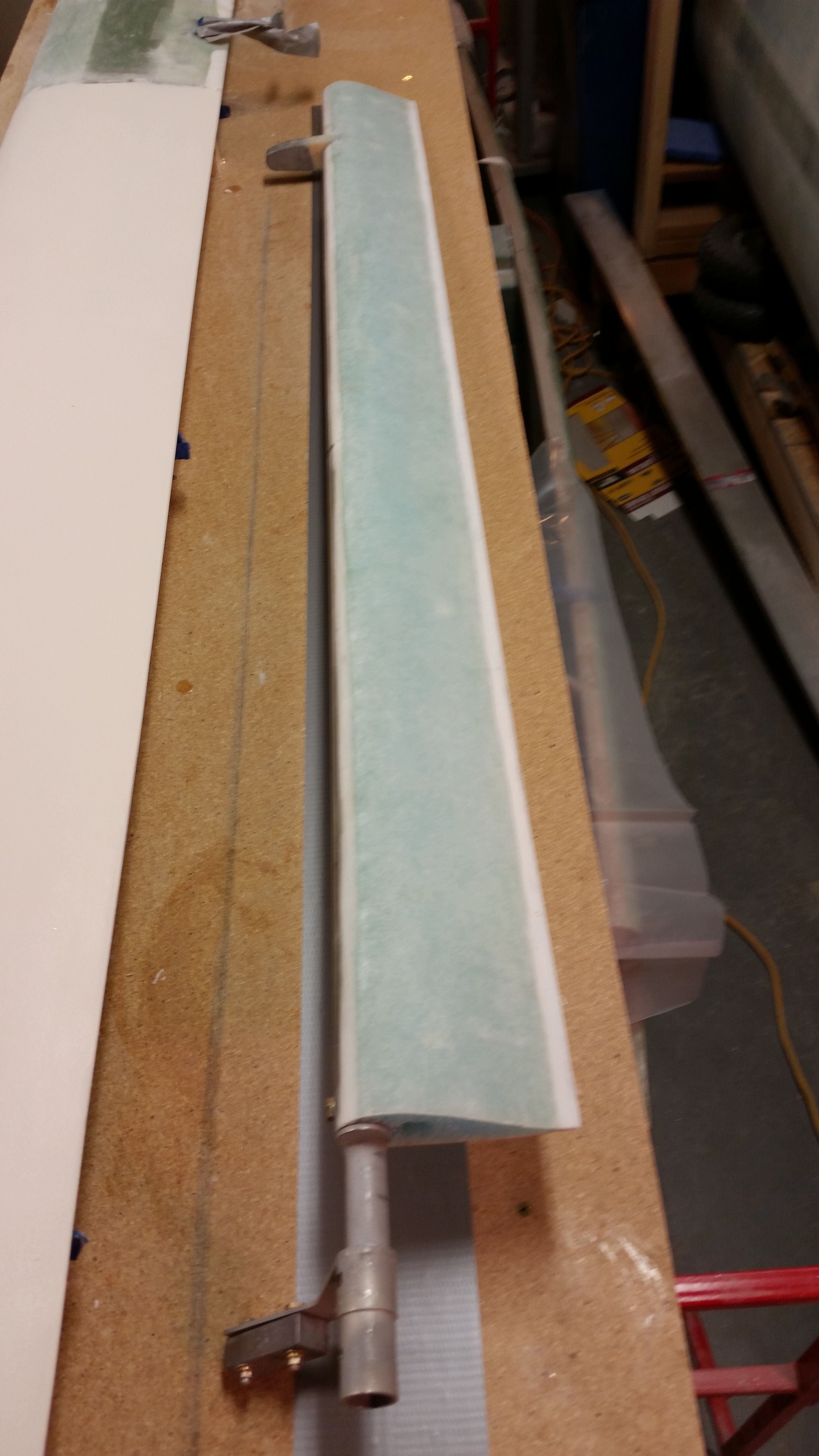
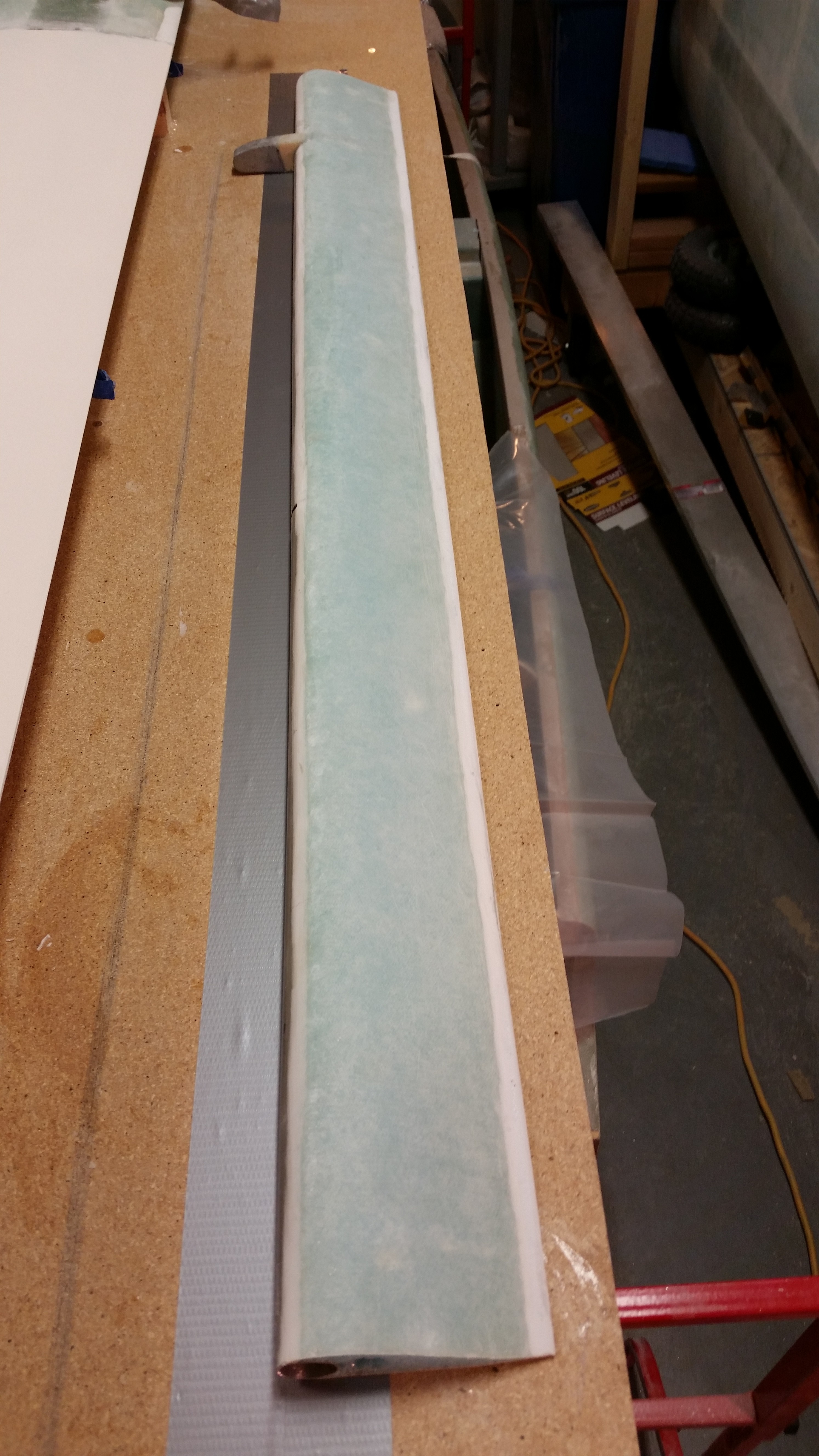
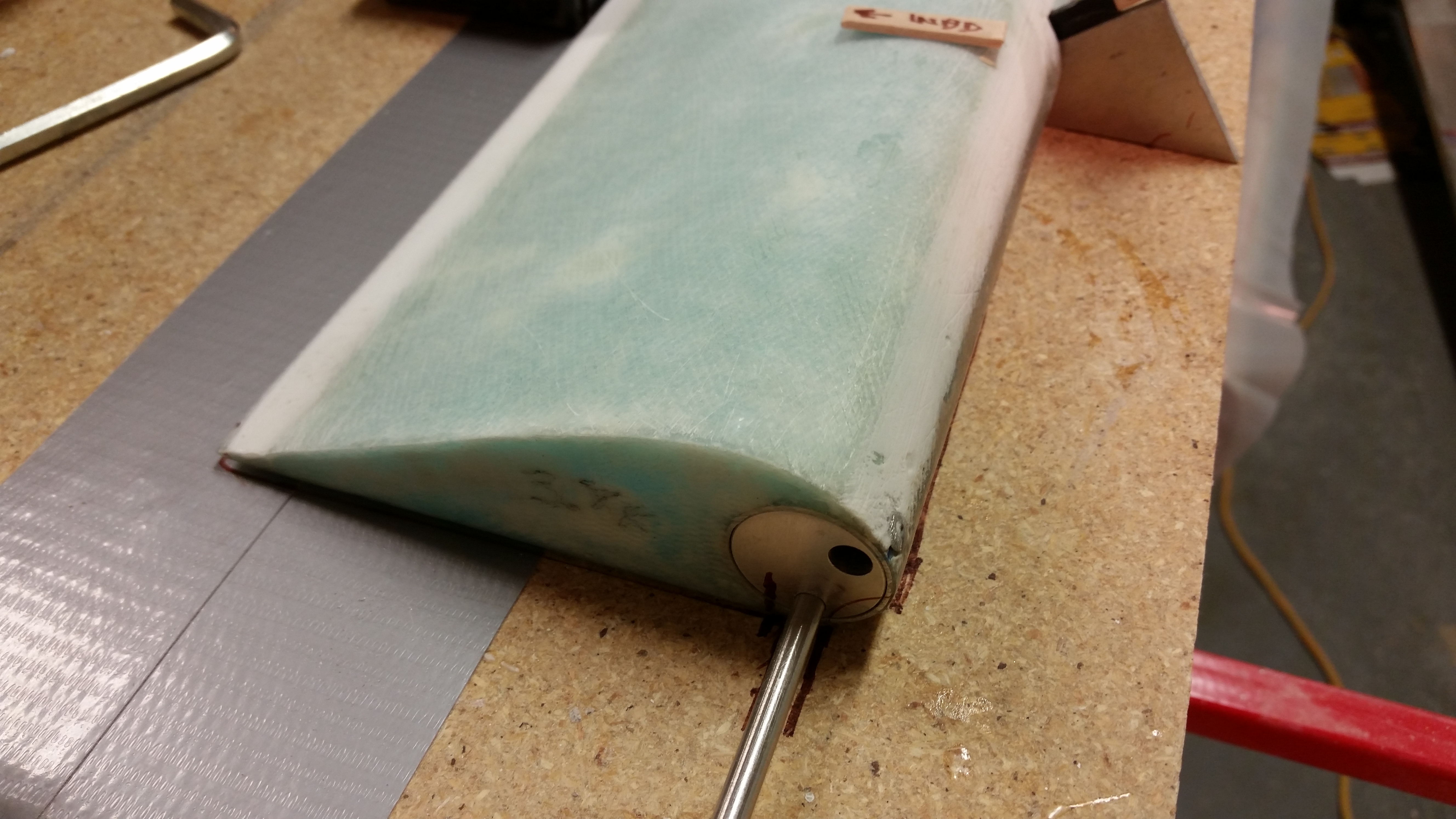
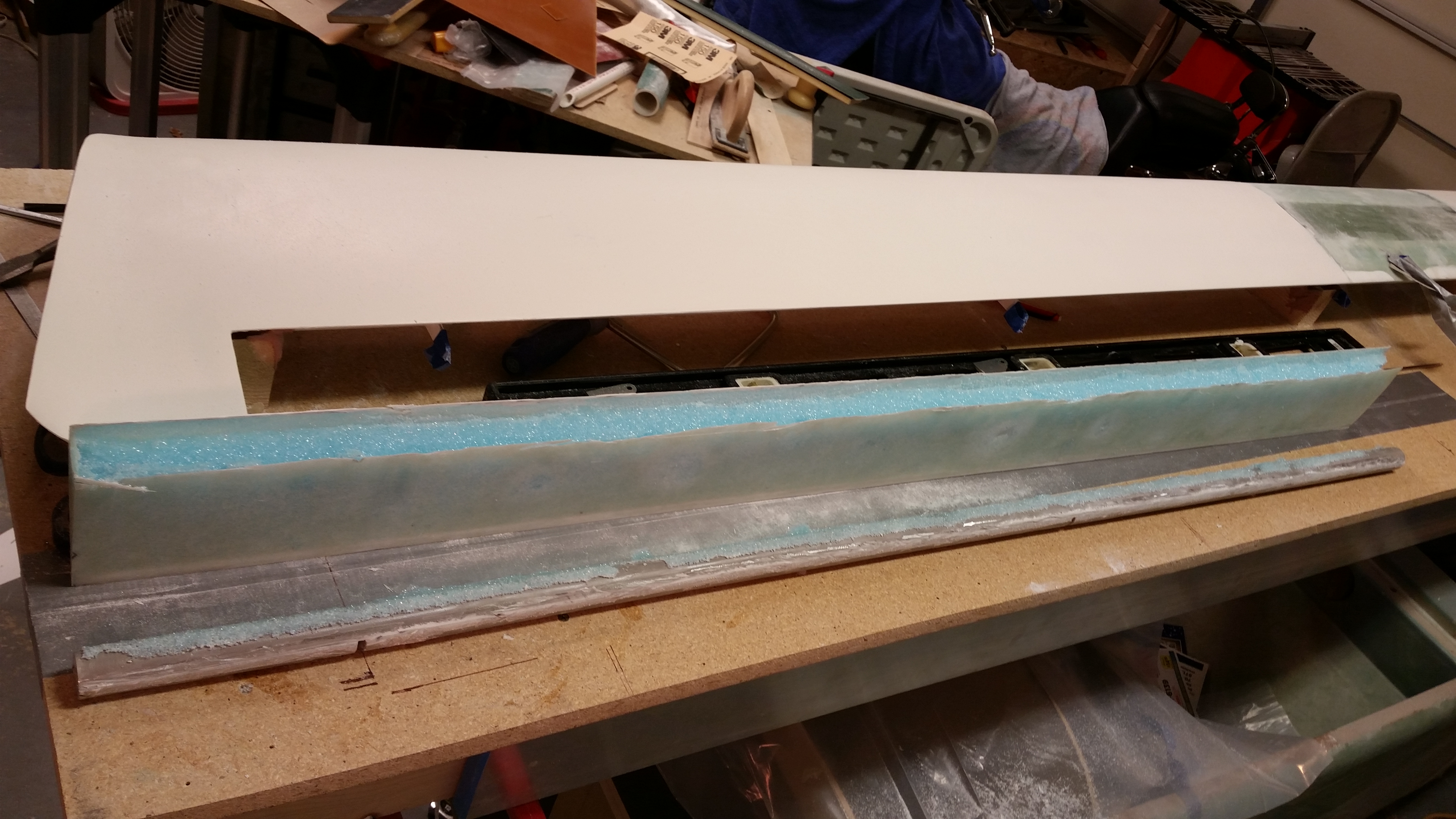
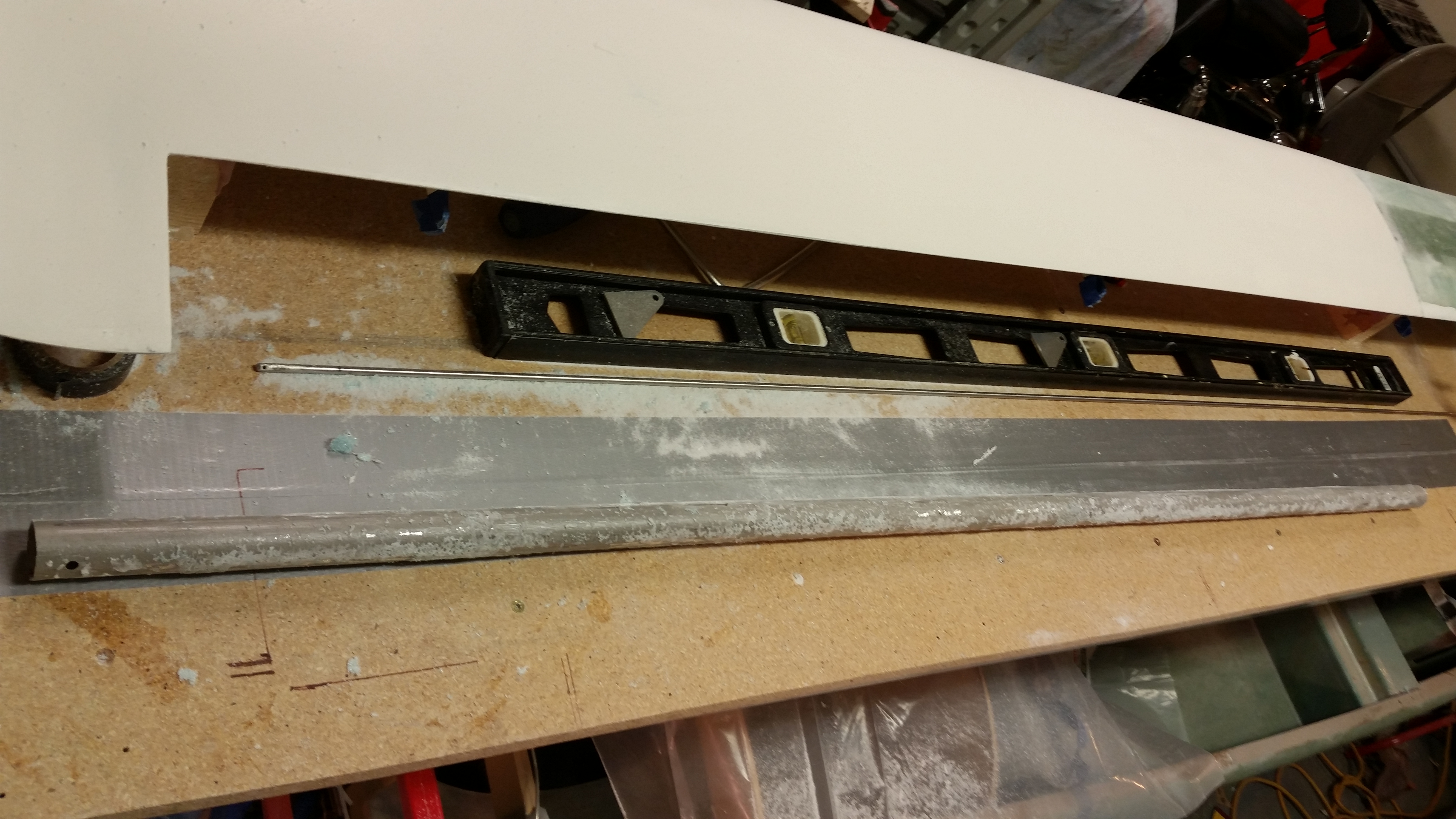
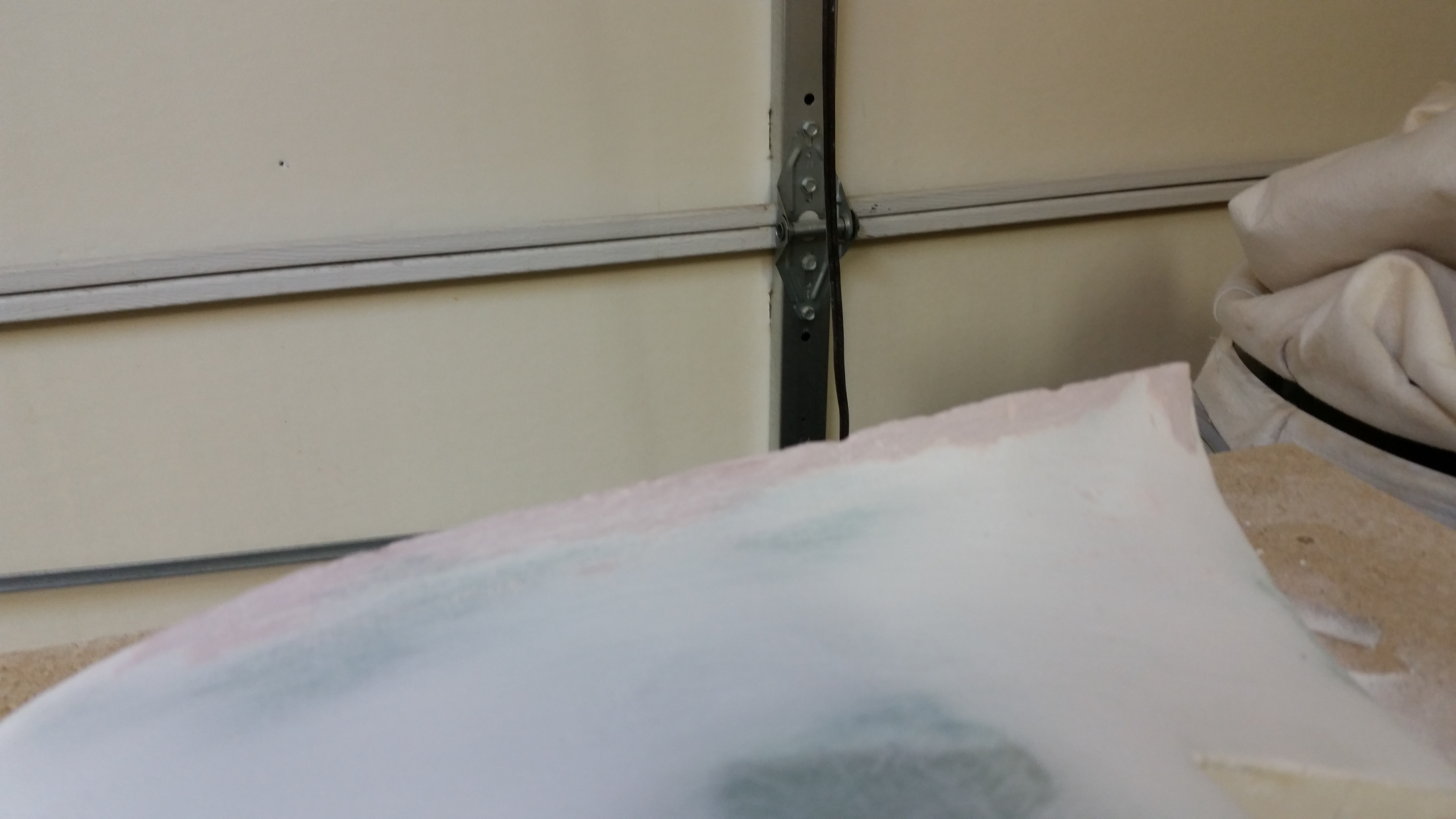
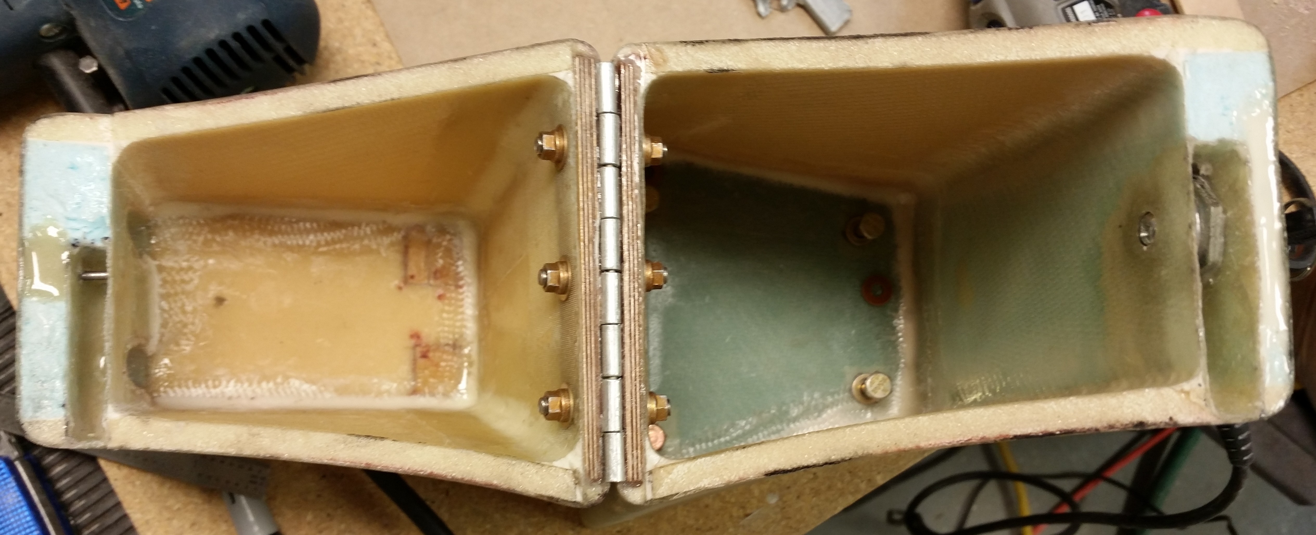
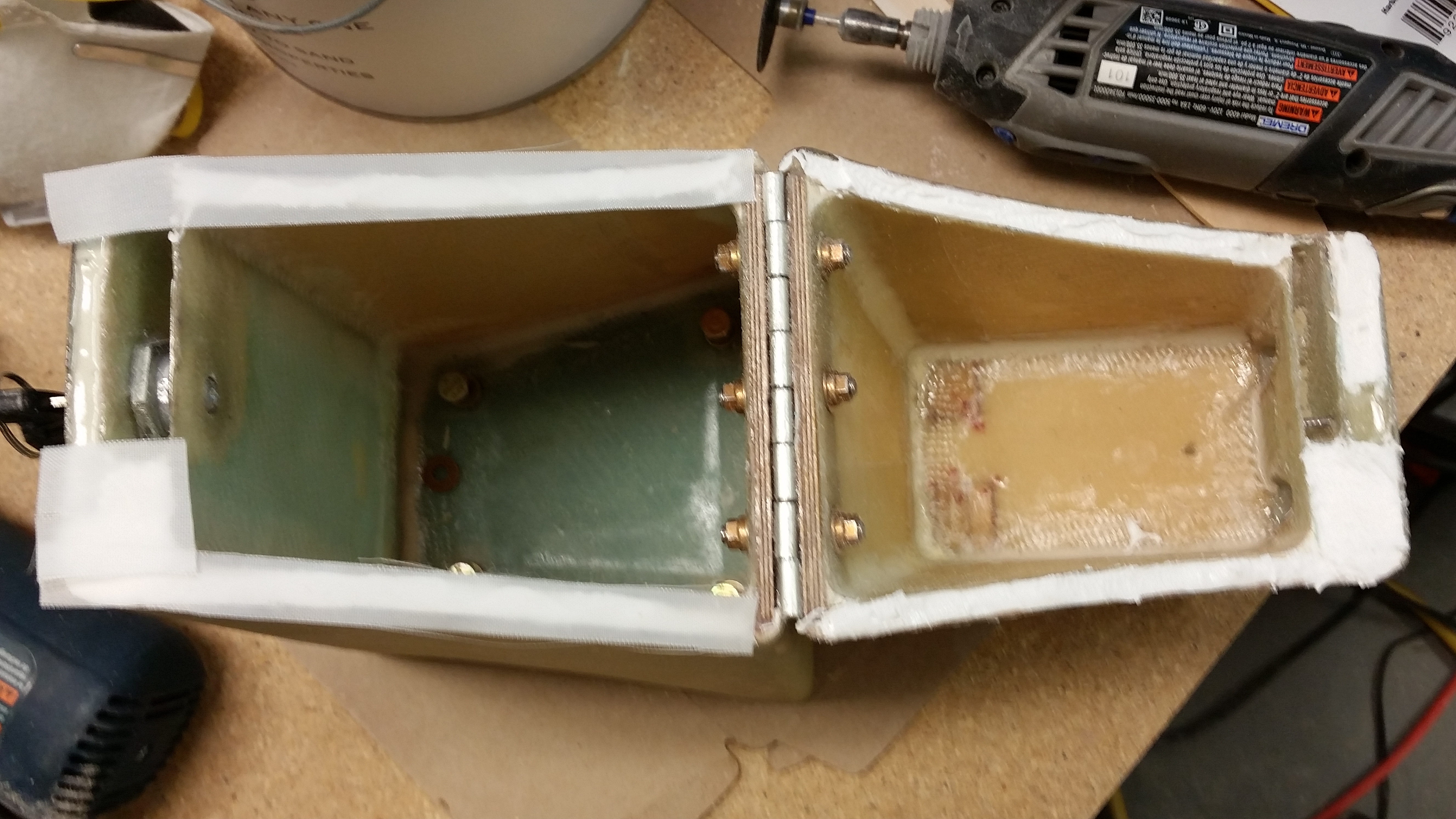
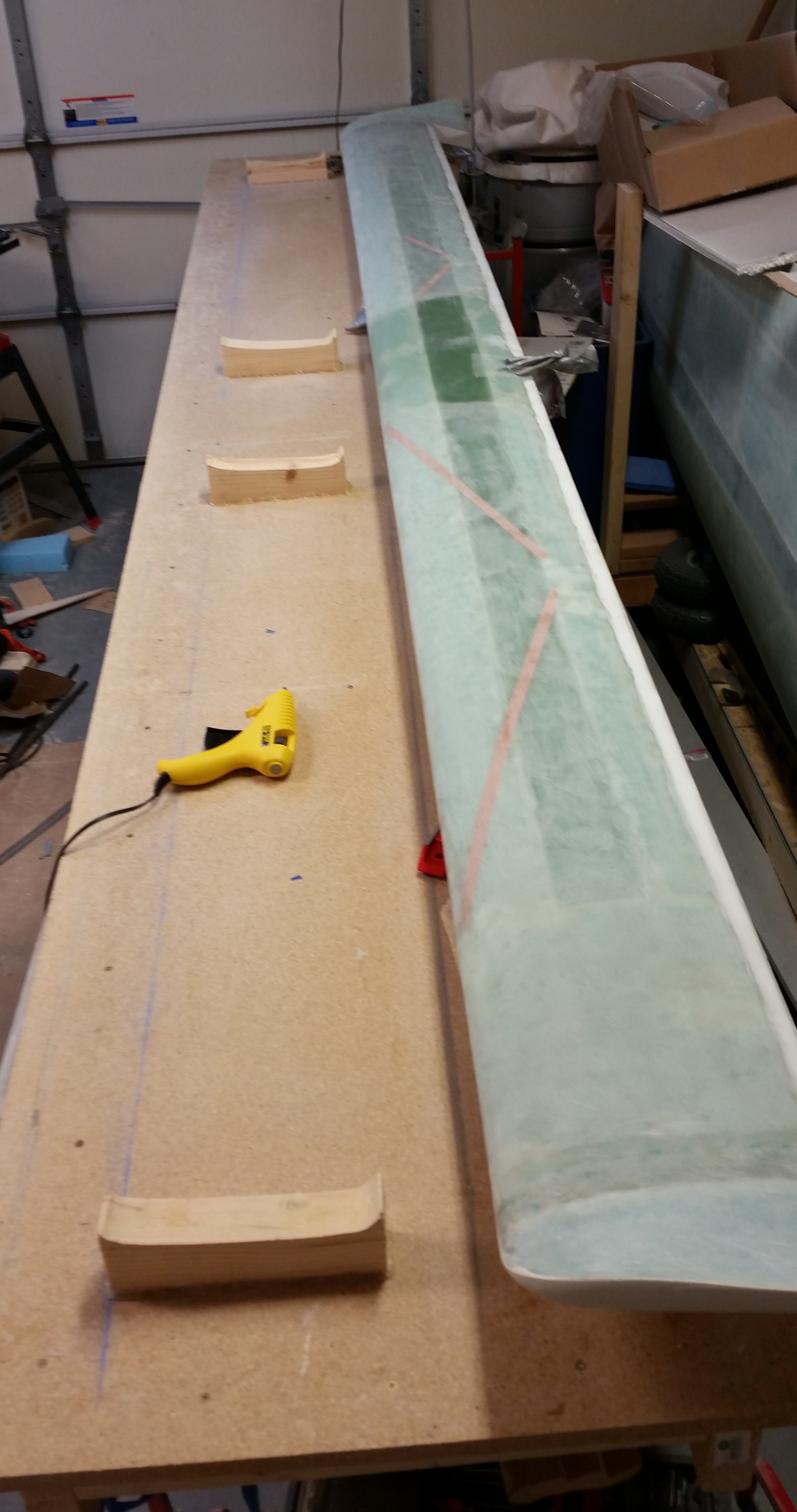
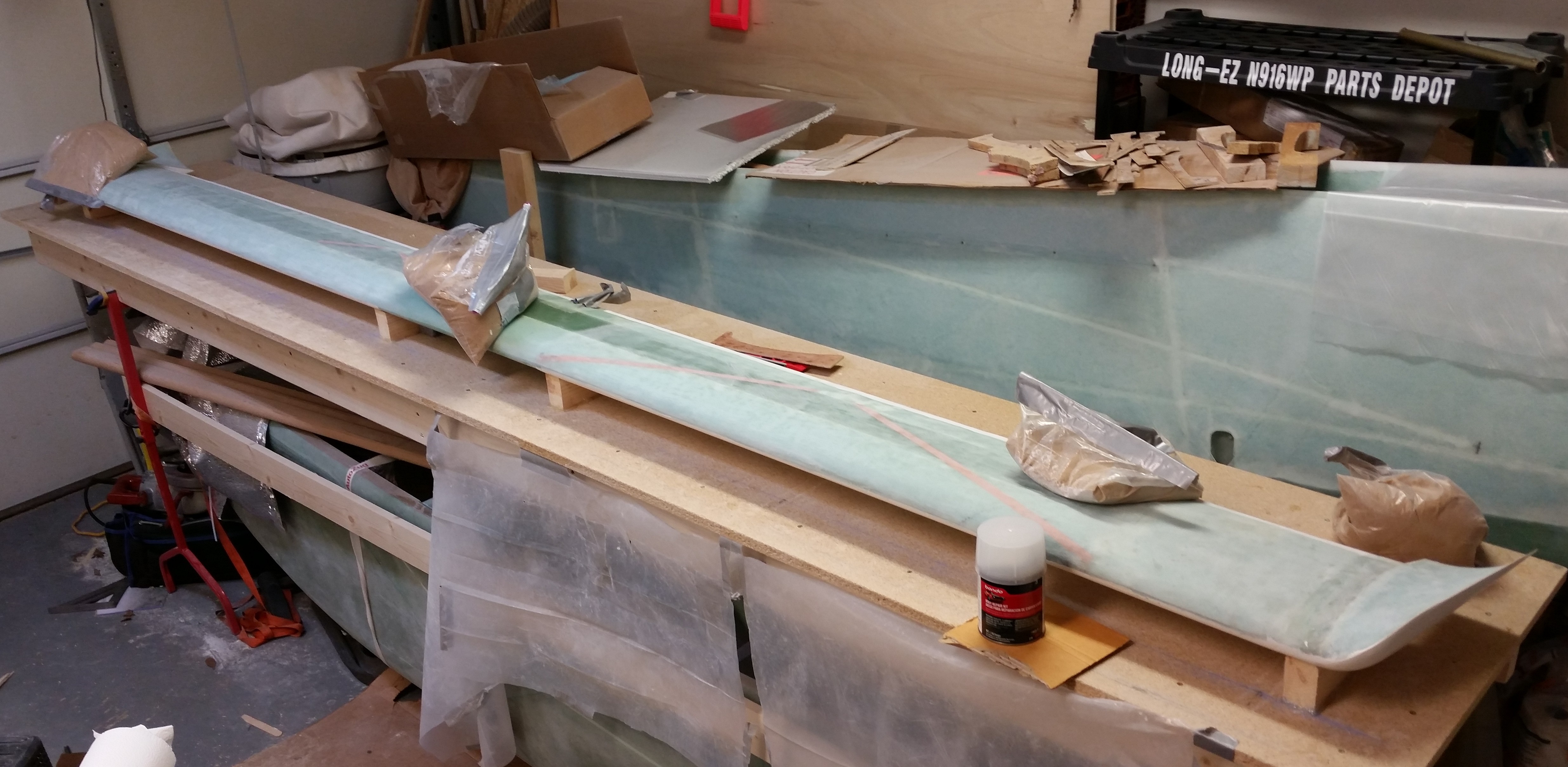
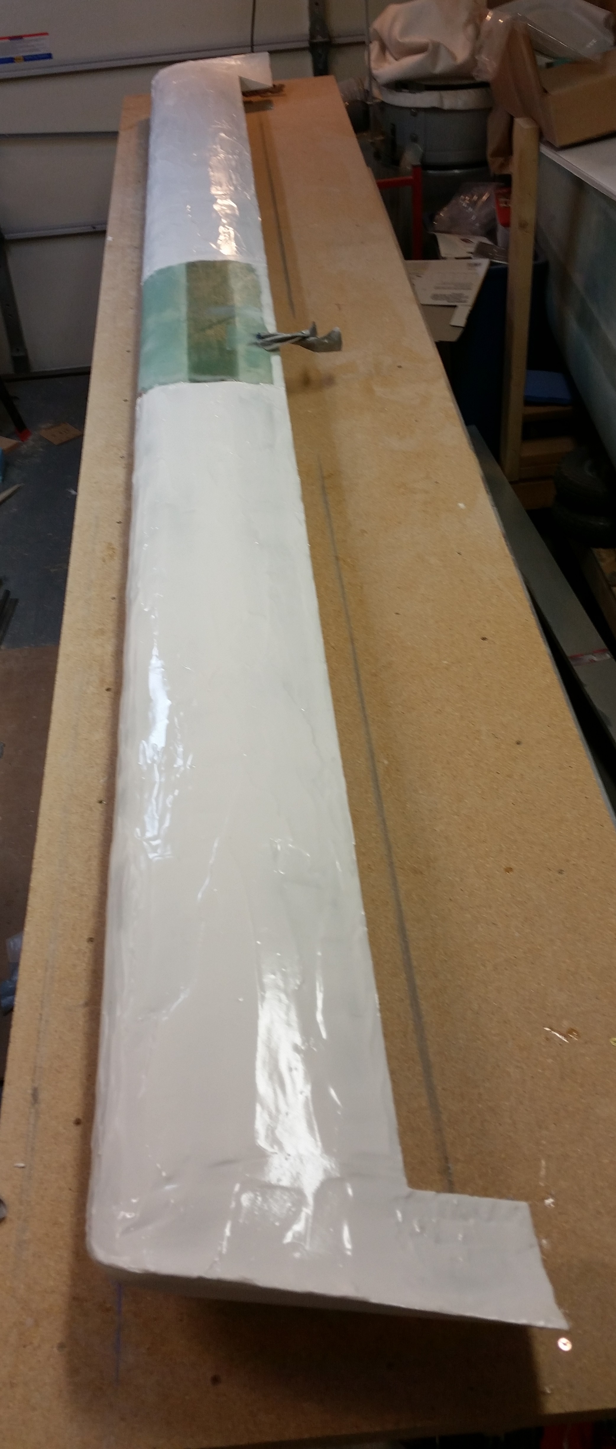
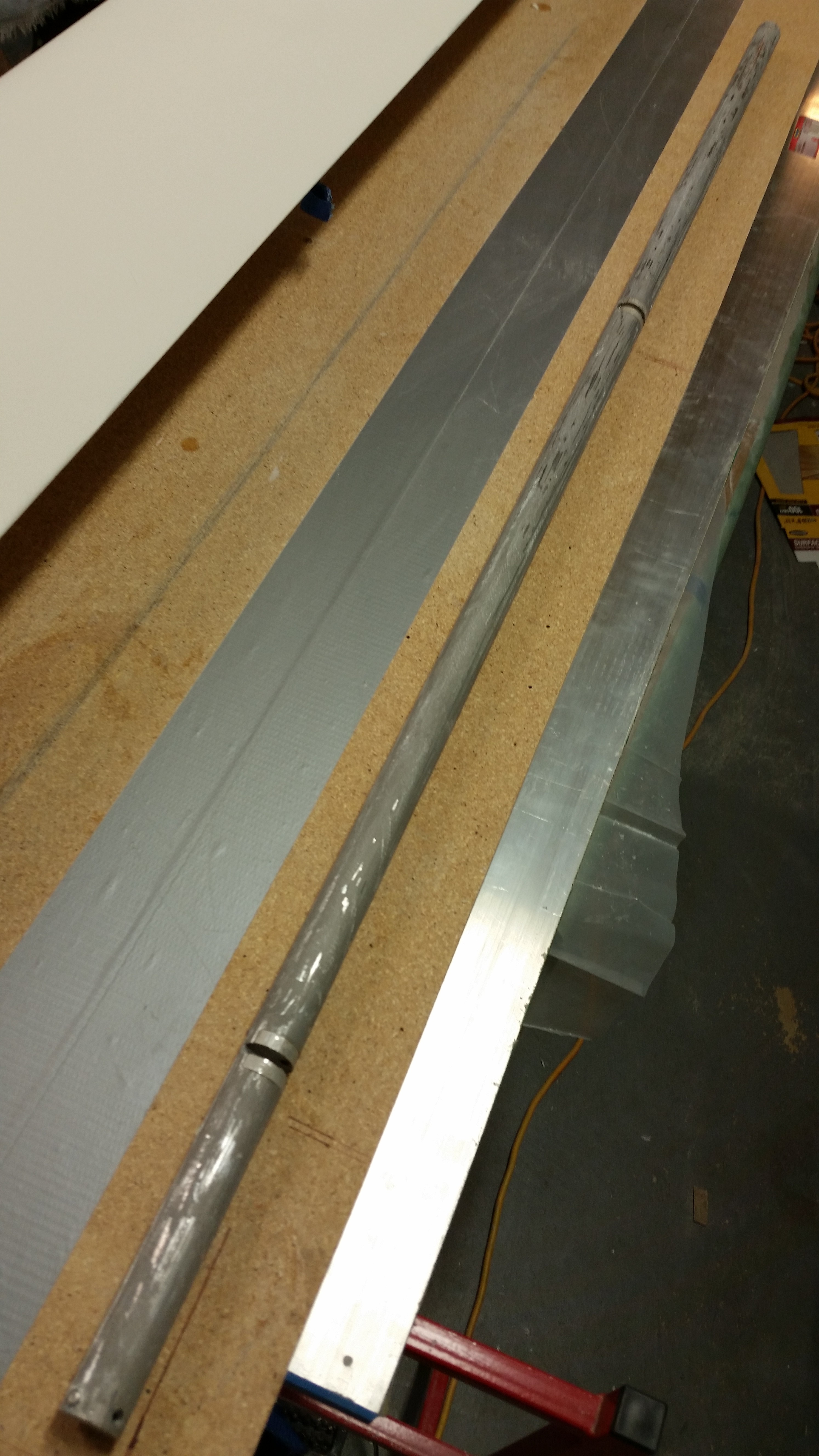
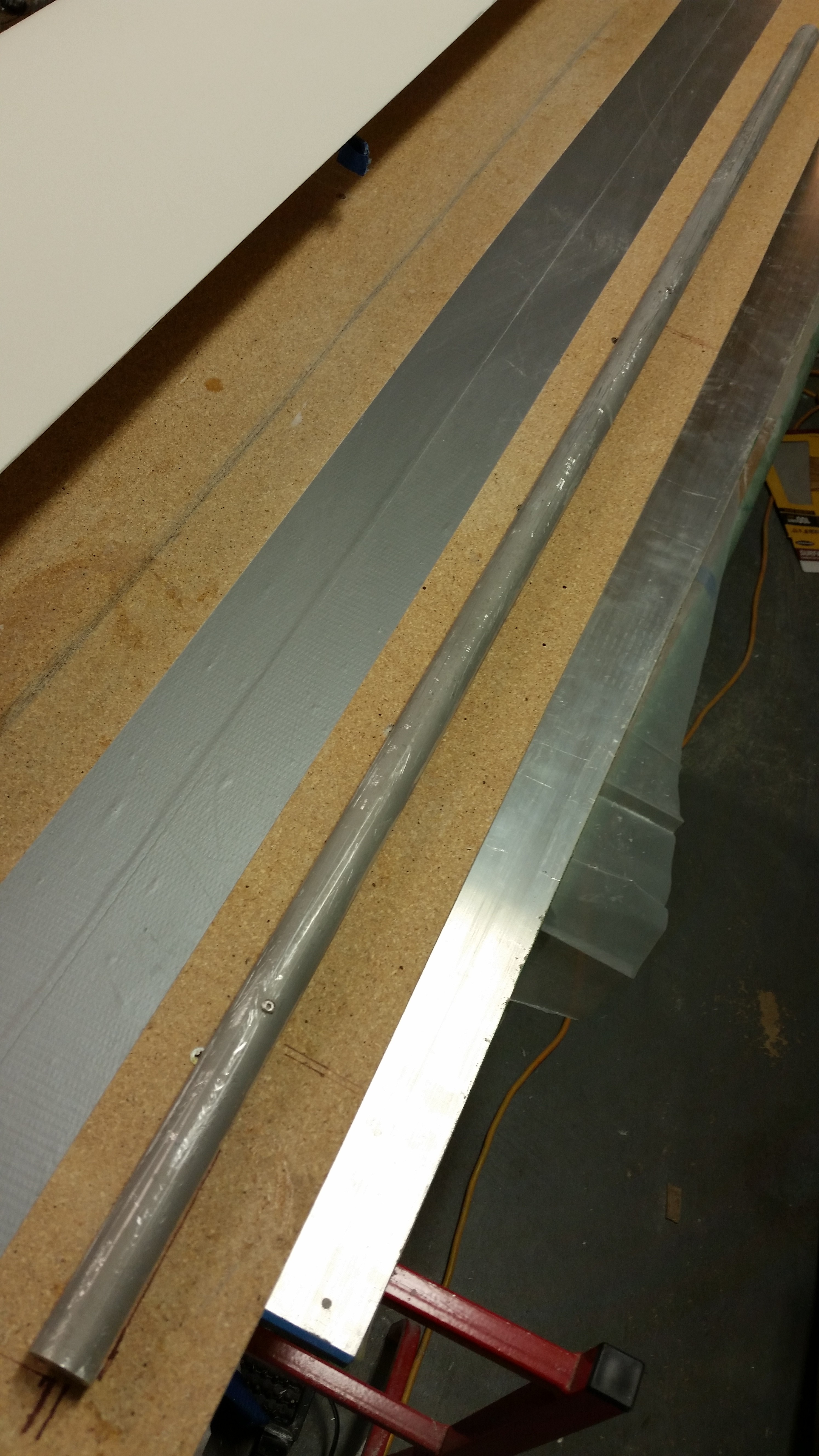
Here’s a couple shots of the elevator tube in its current state.  I would say it’s about 90% clean, and after I shot these pics I put it back in the PVC tube to soak in the vinegar over night.

Elevator tubeElevator tube

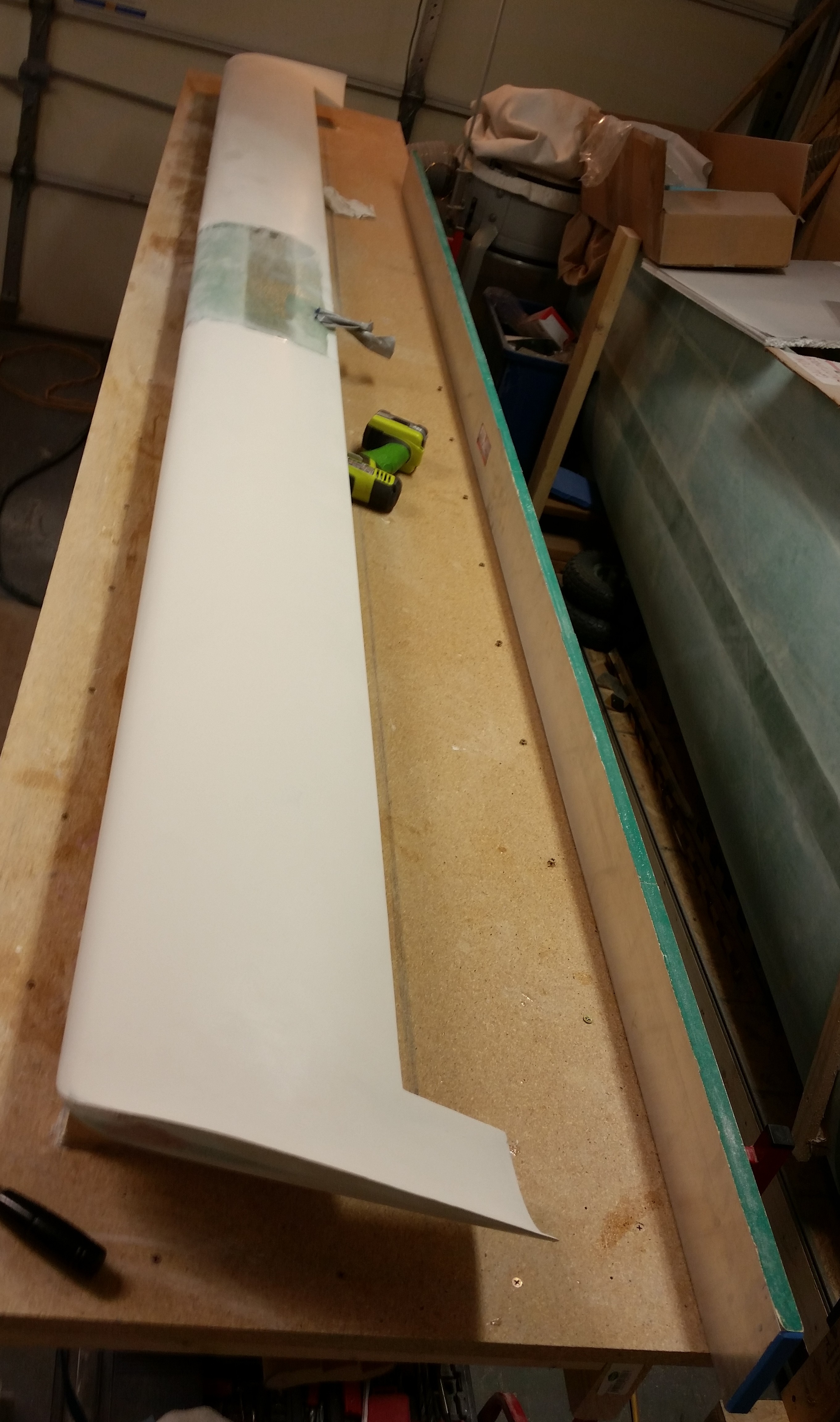
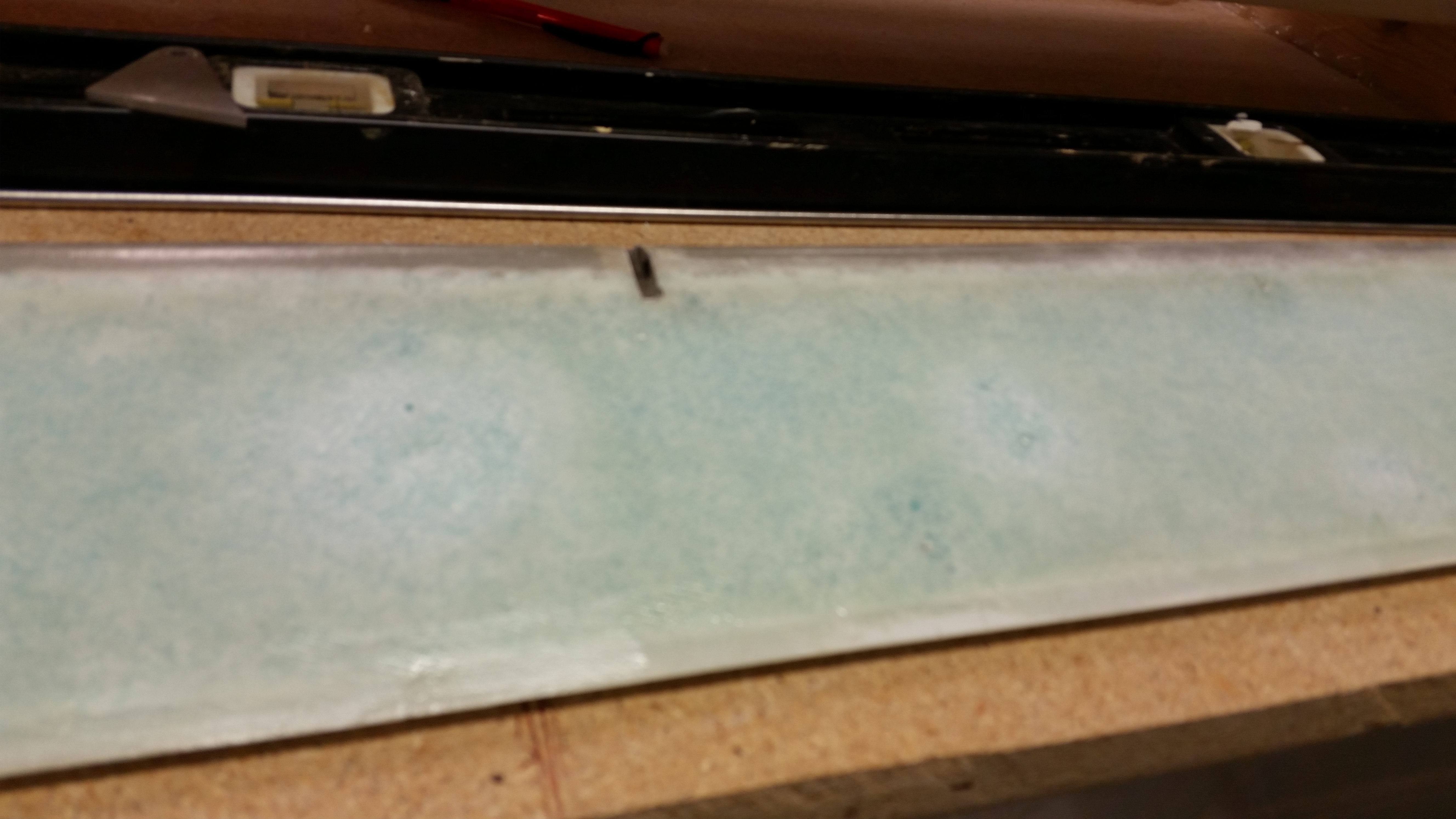
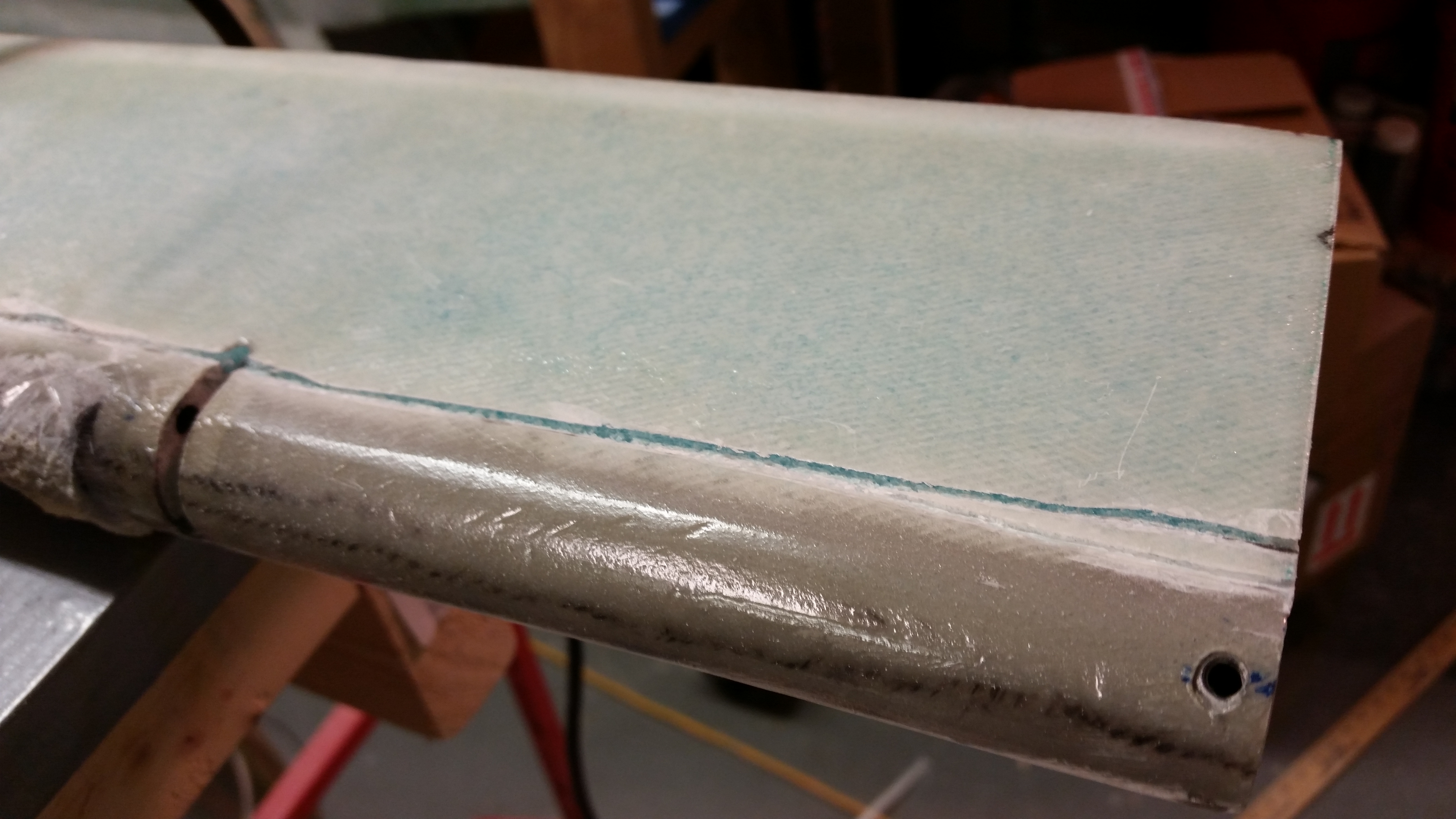
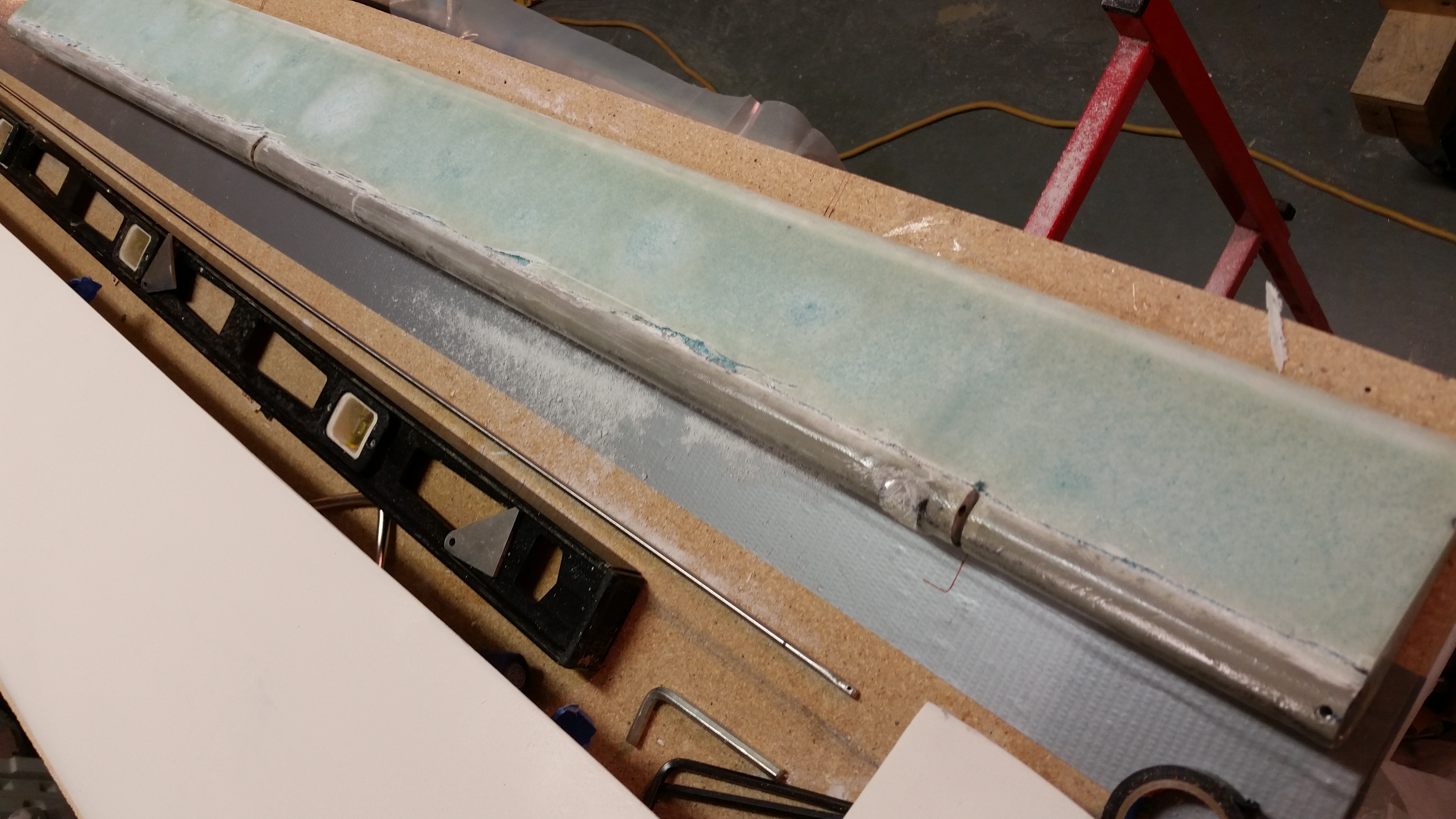
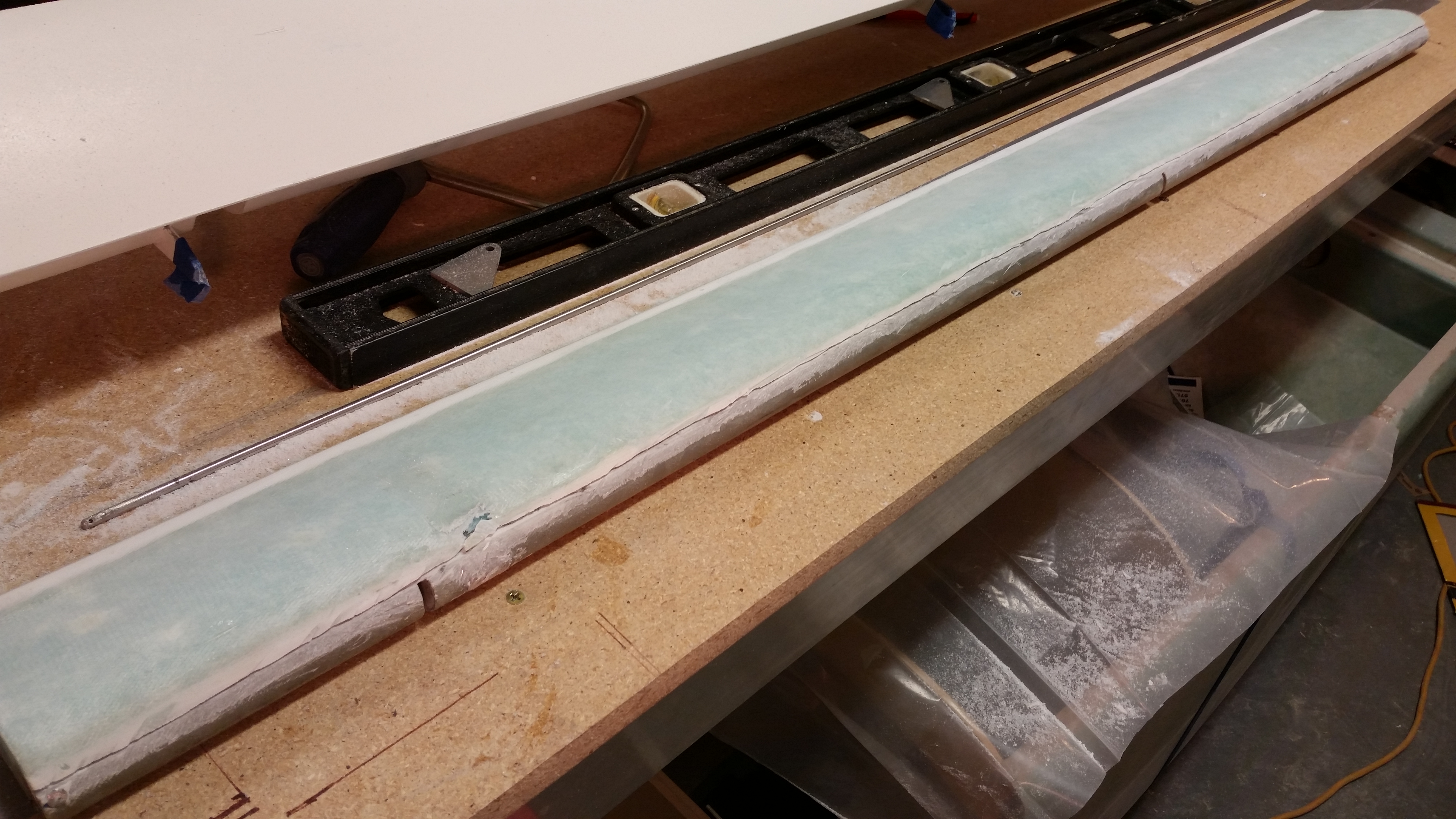
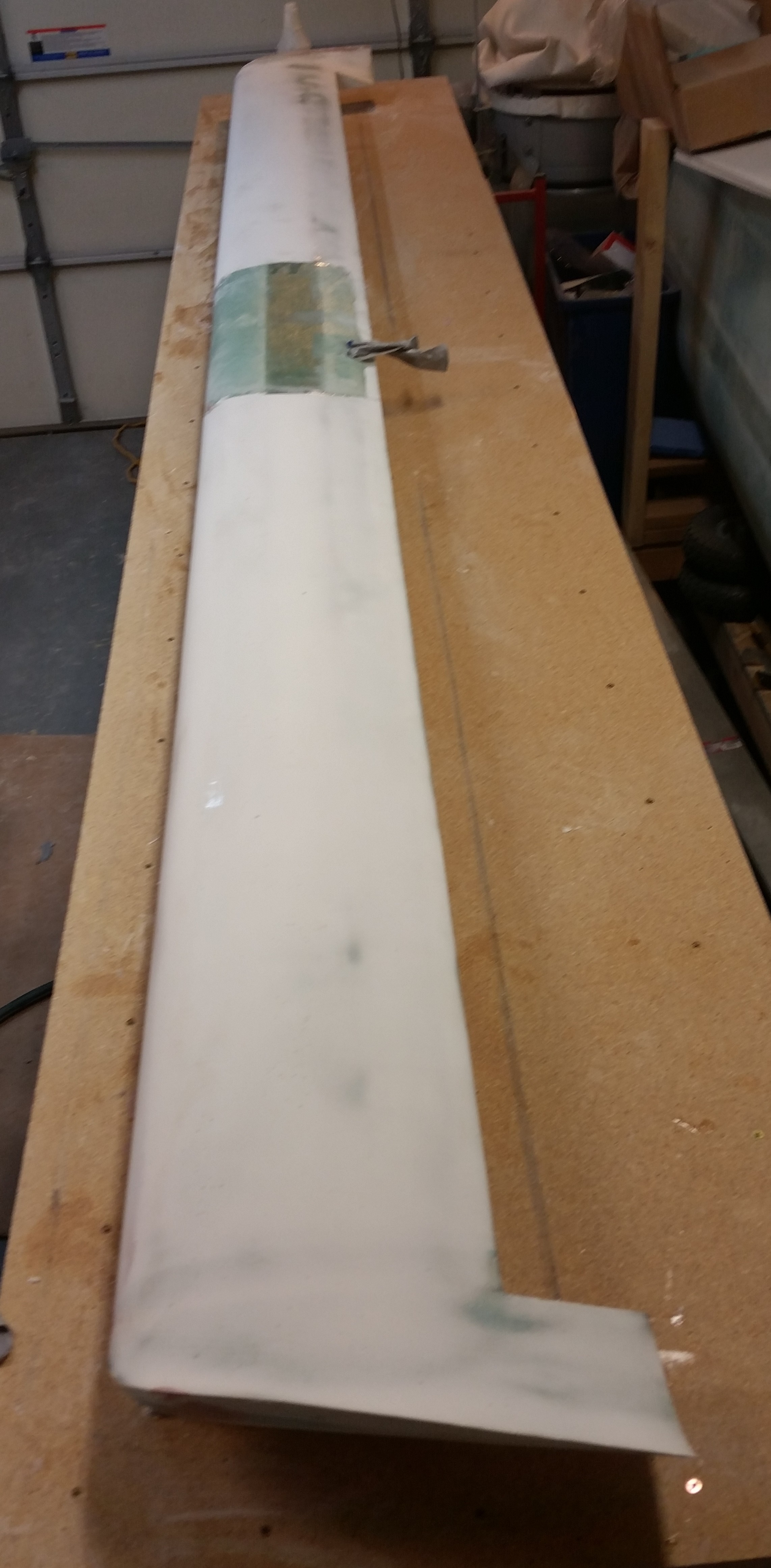
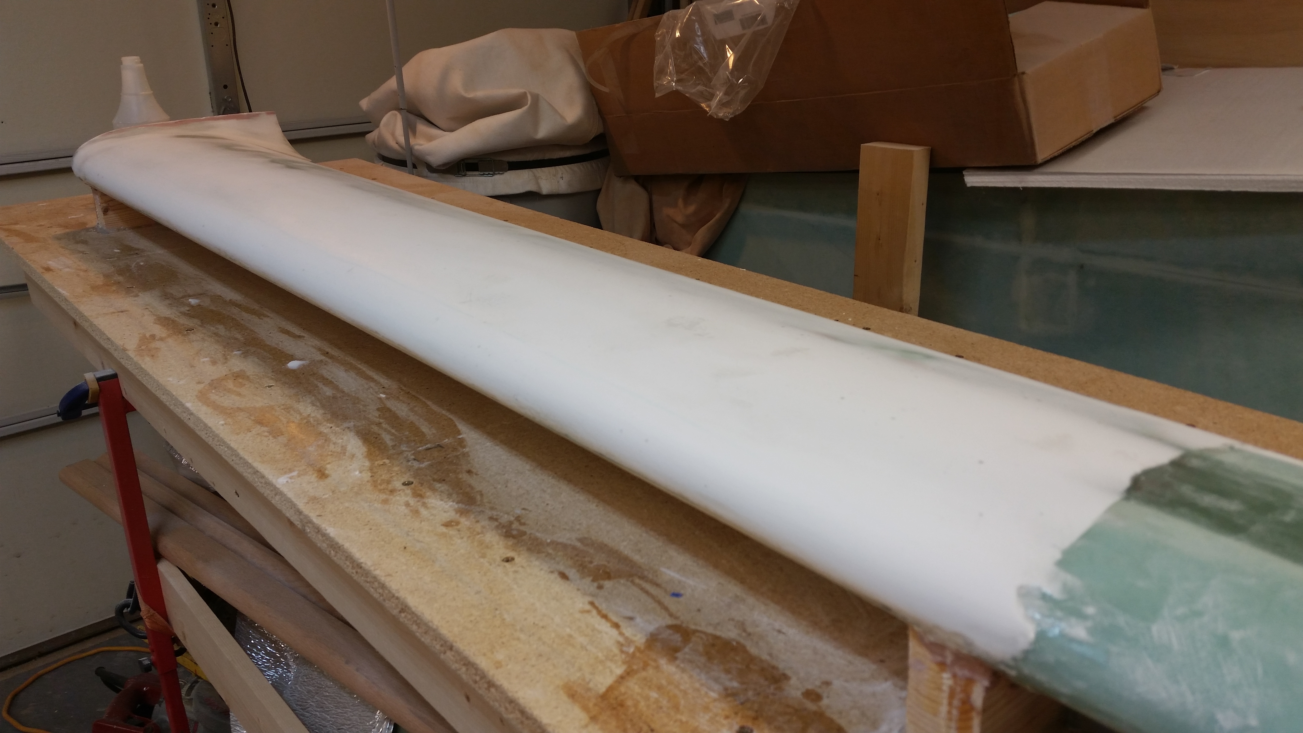
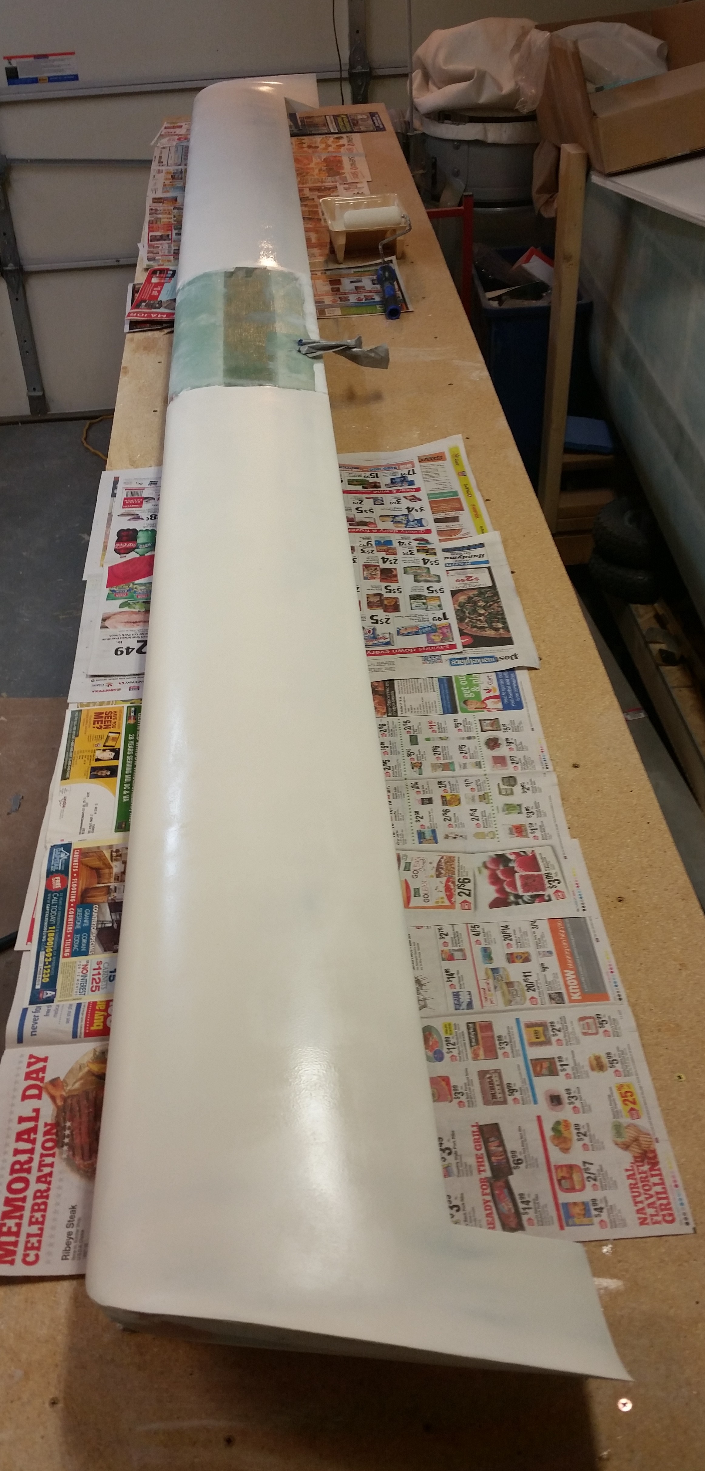
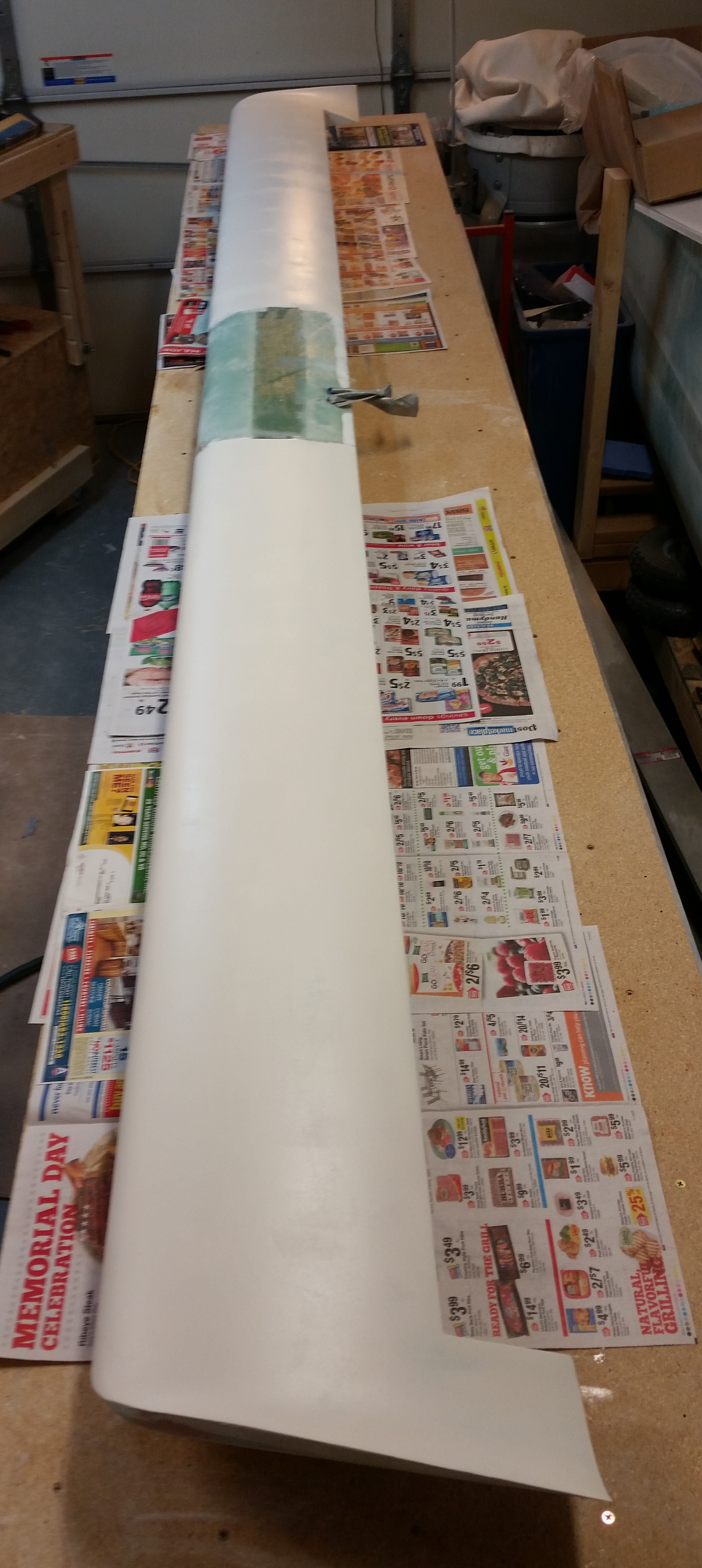
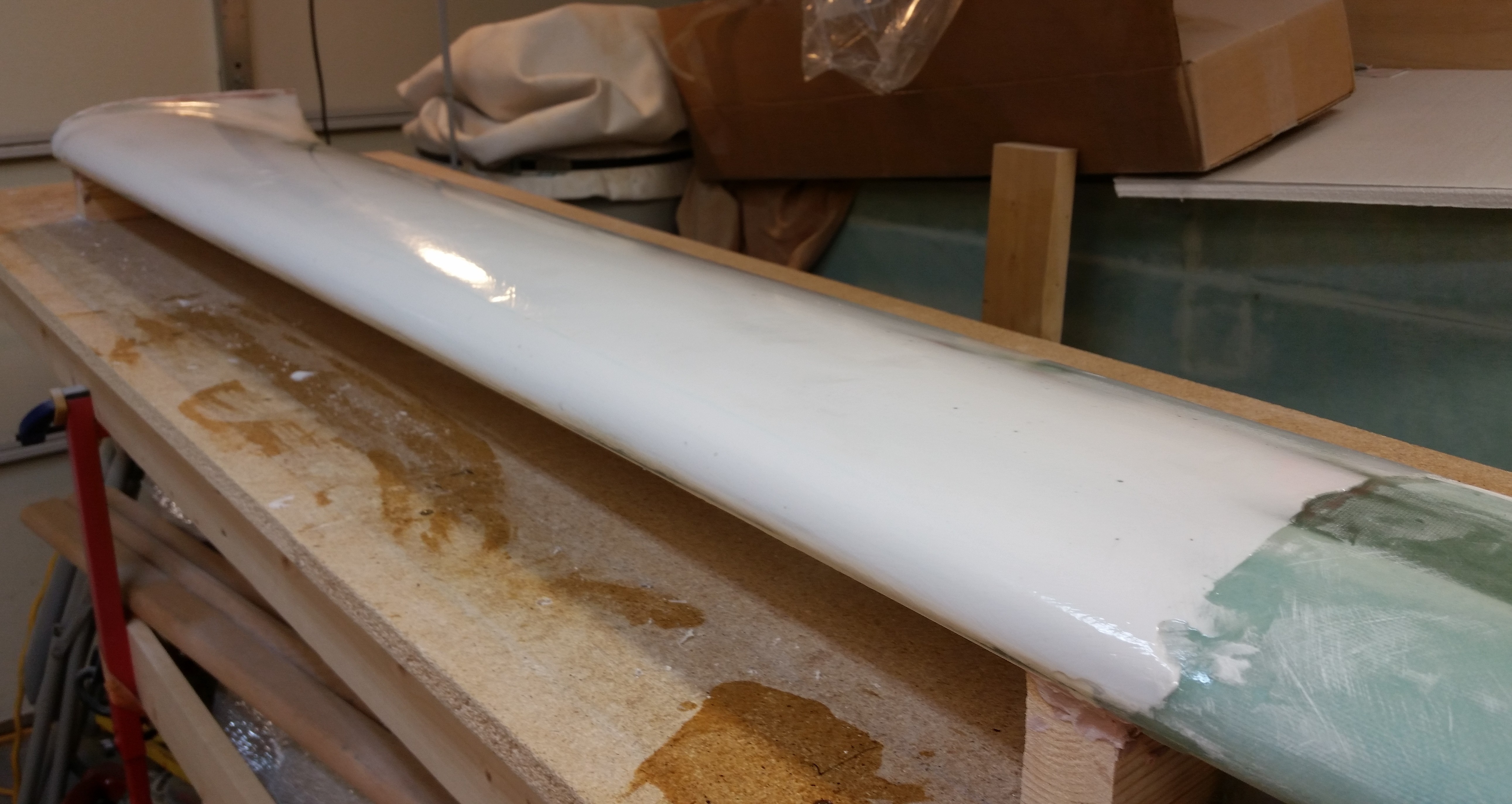
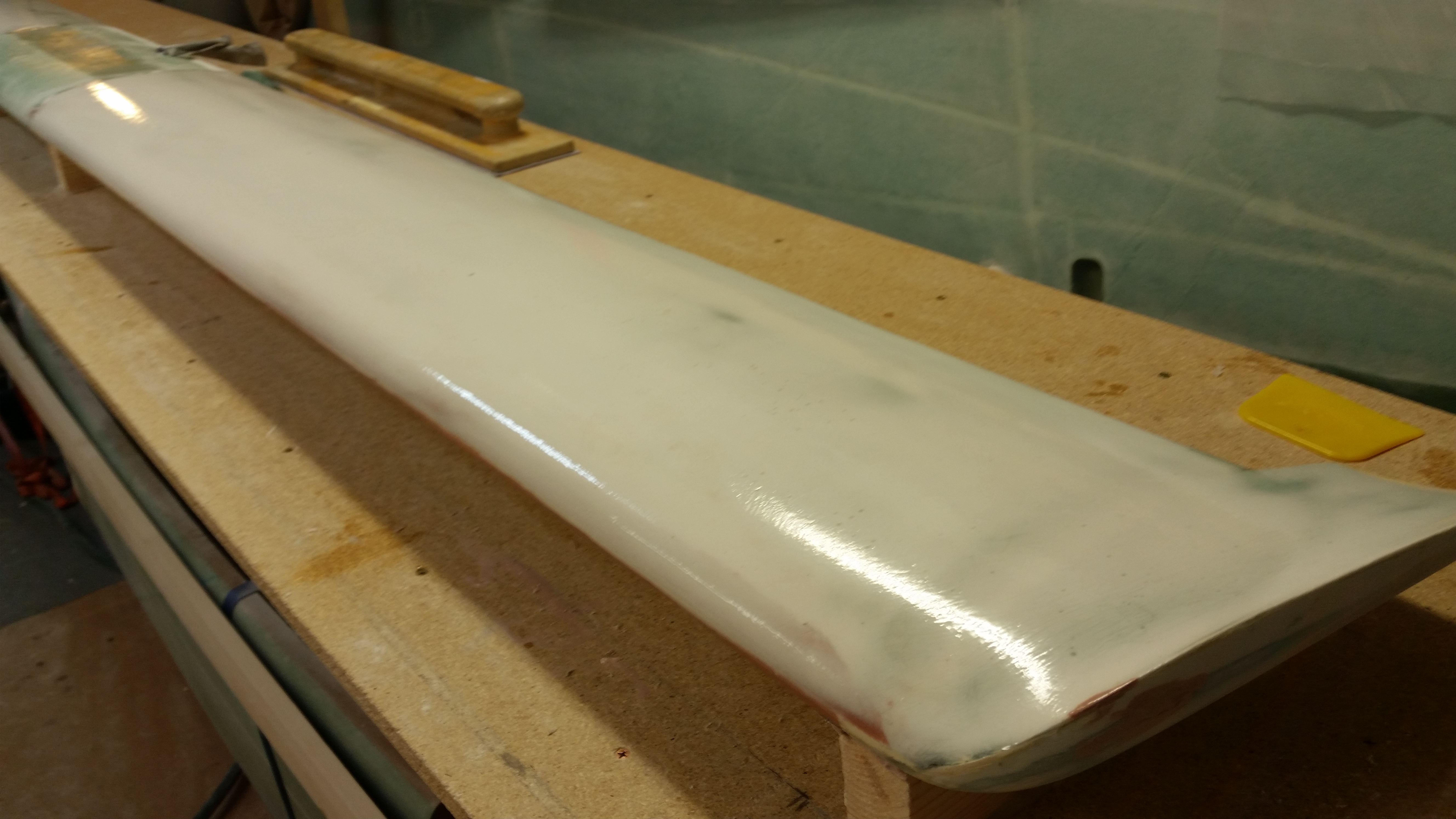
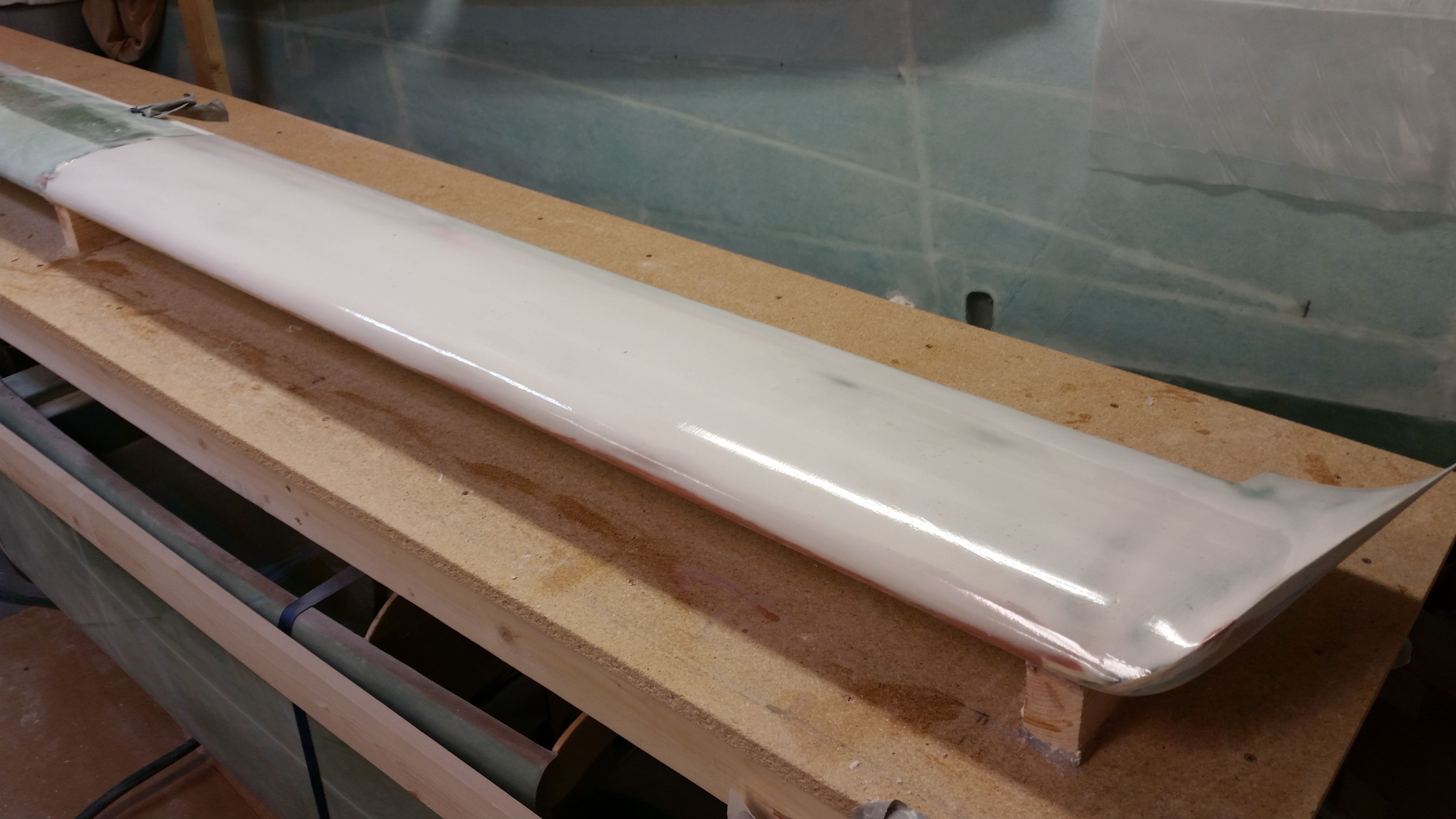
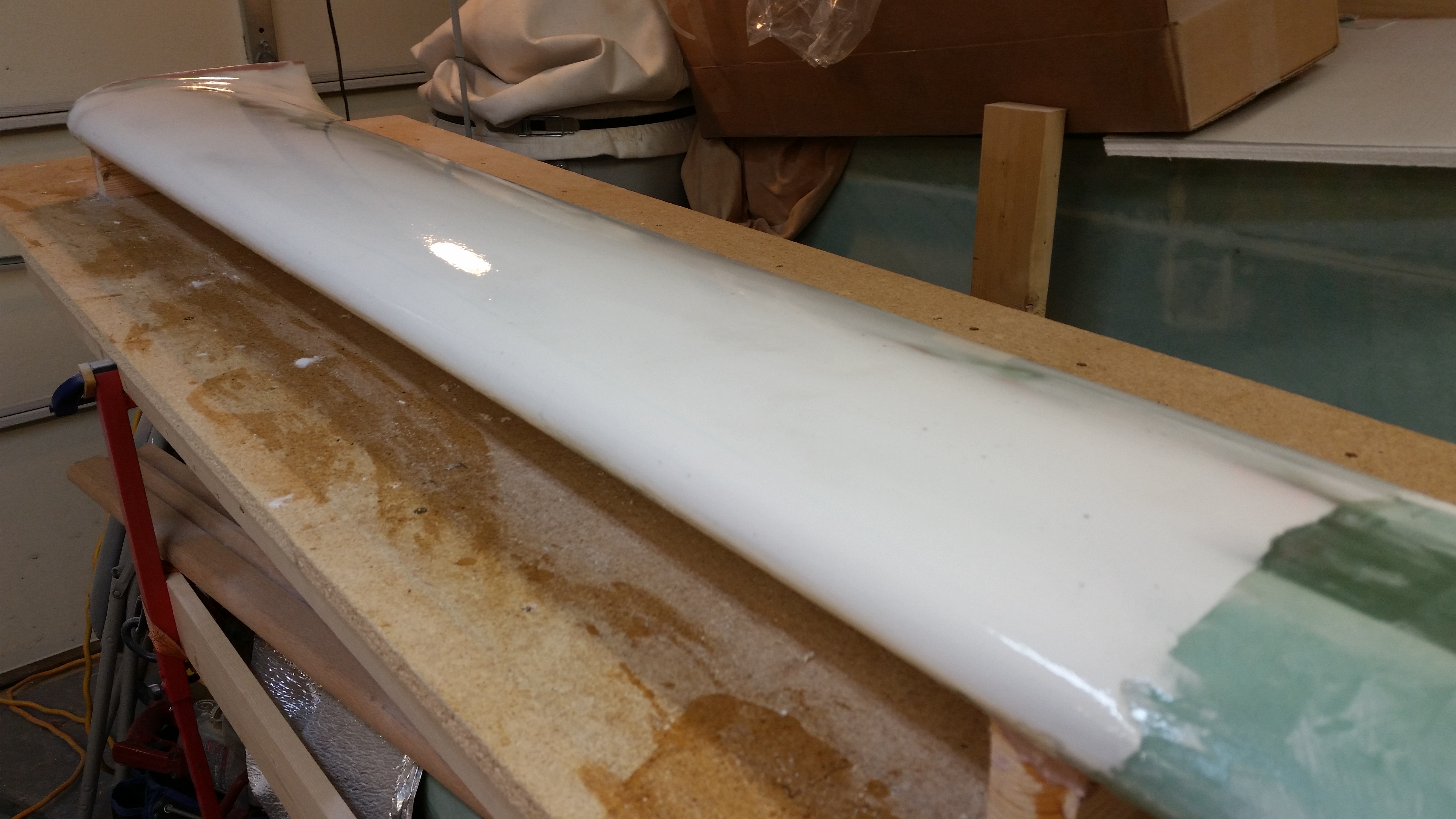
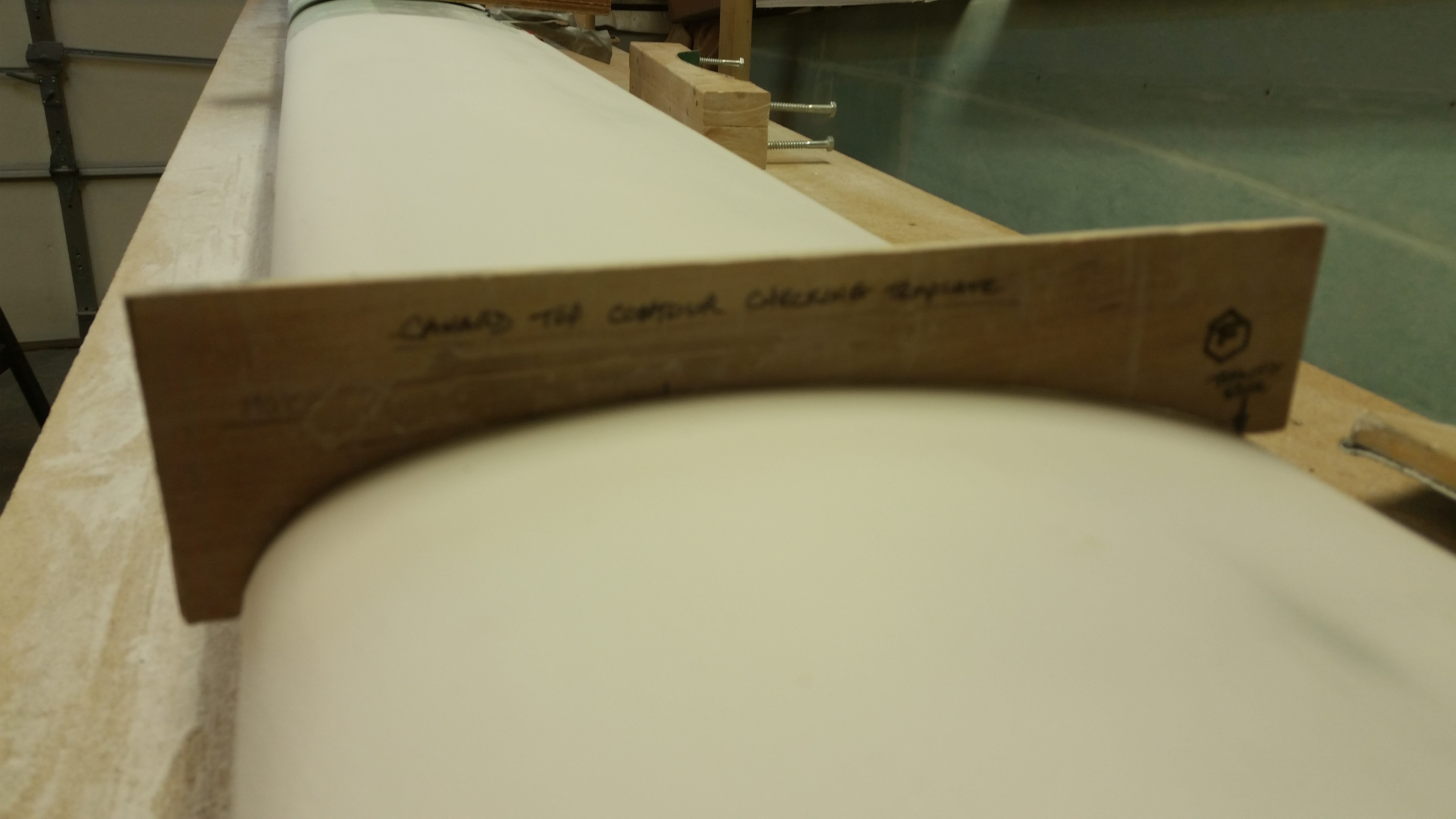
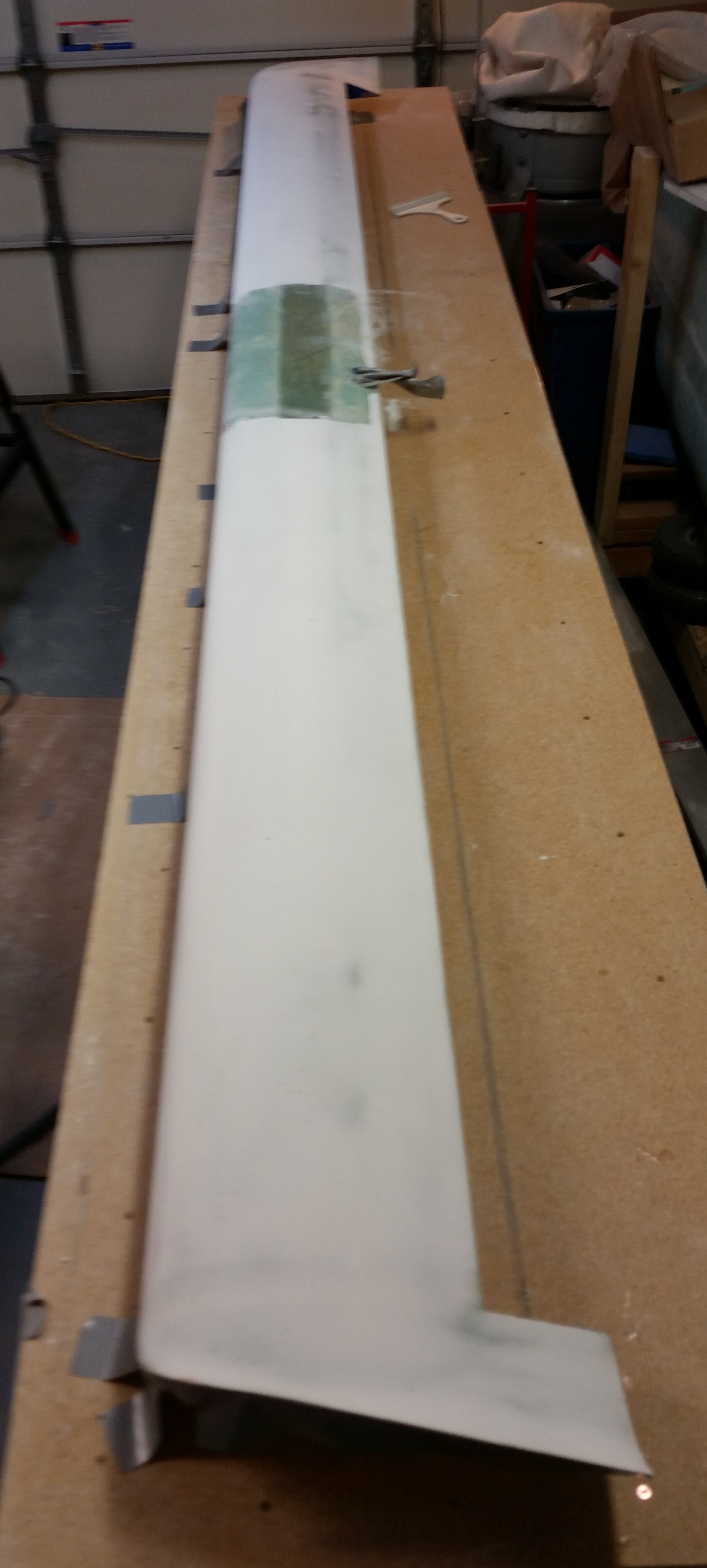
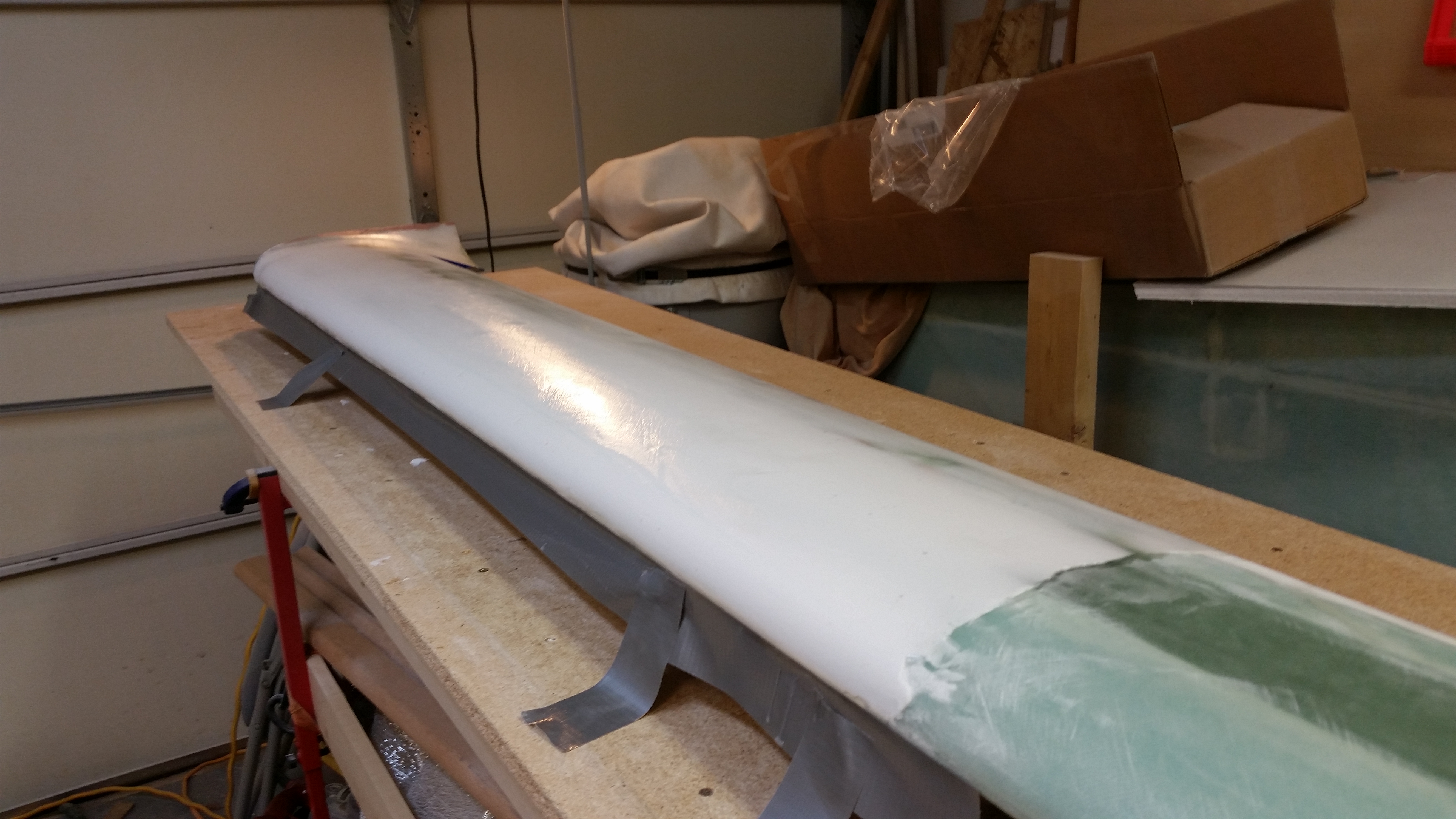
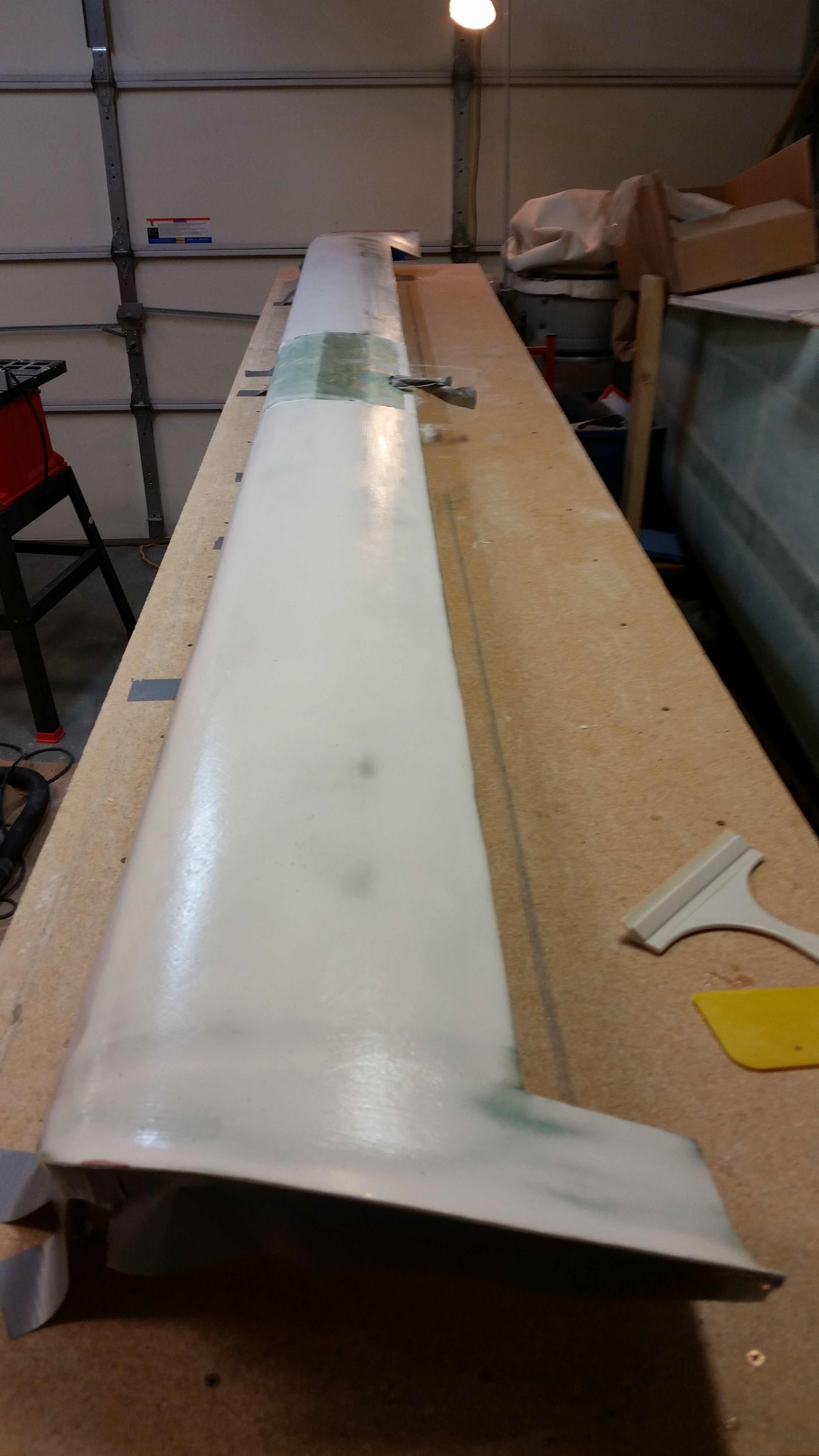
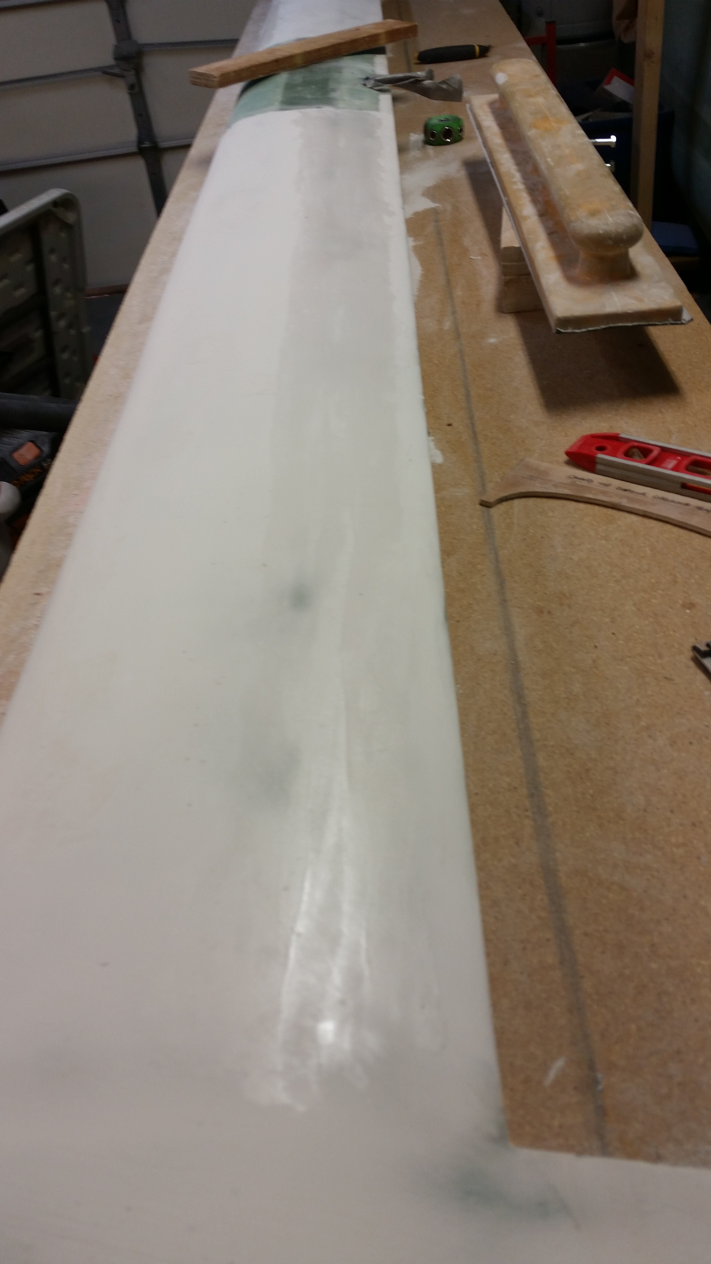
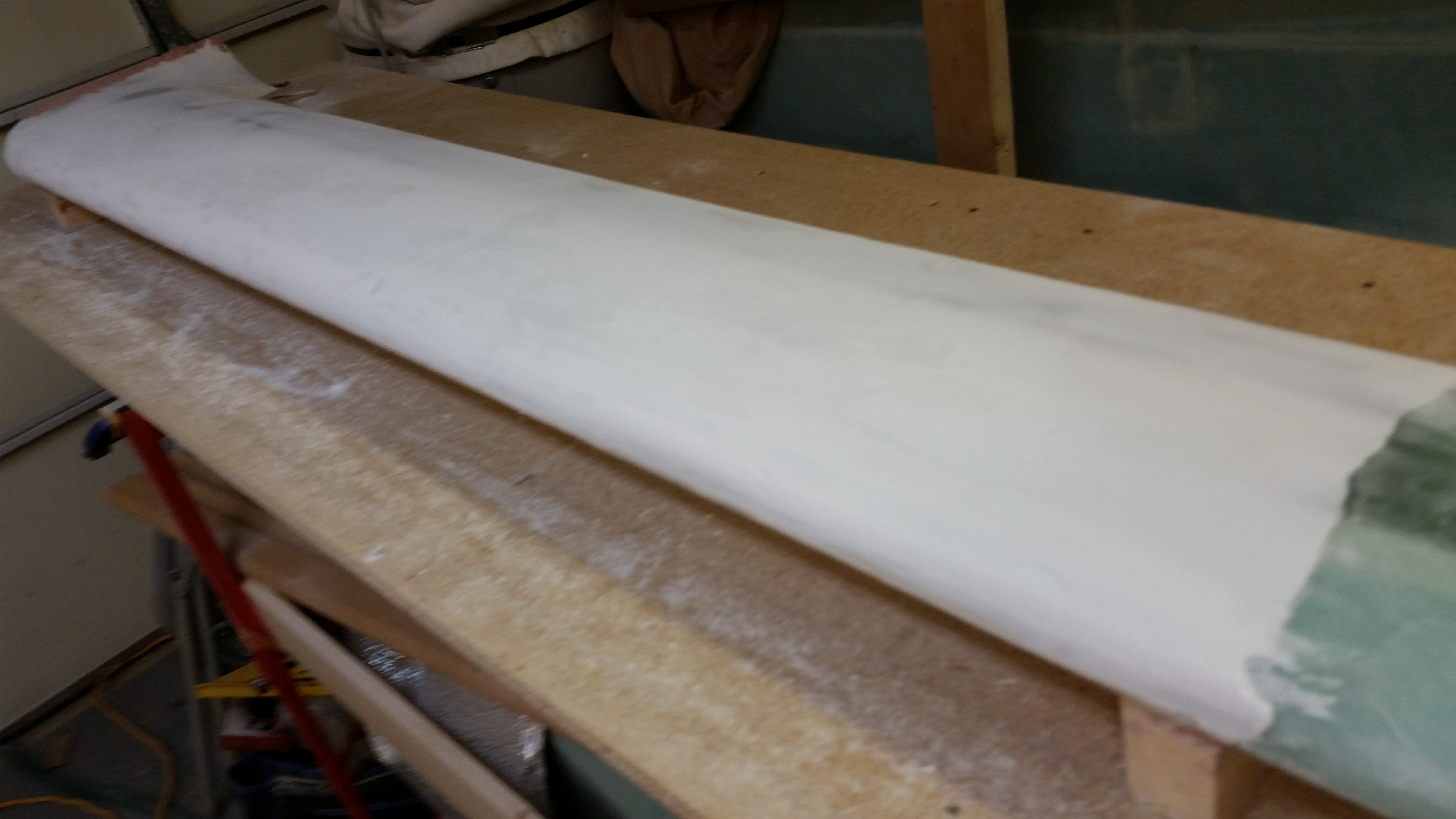
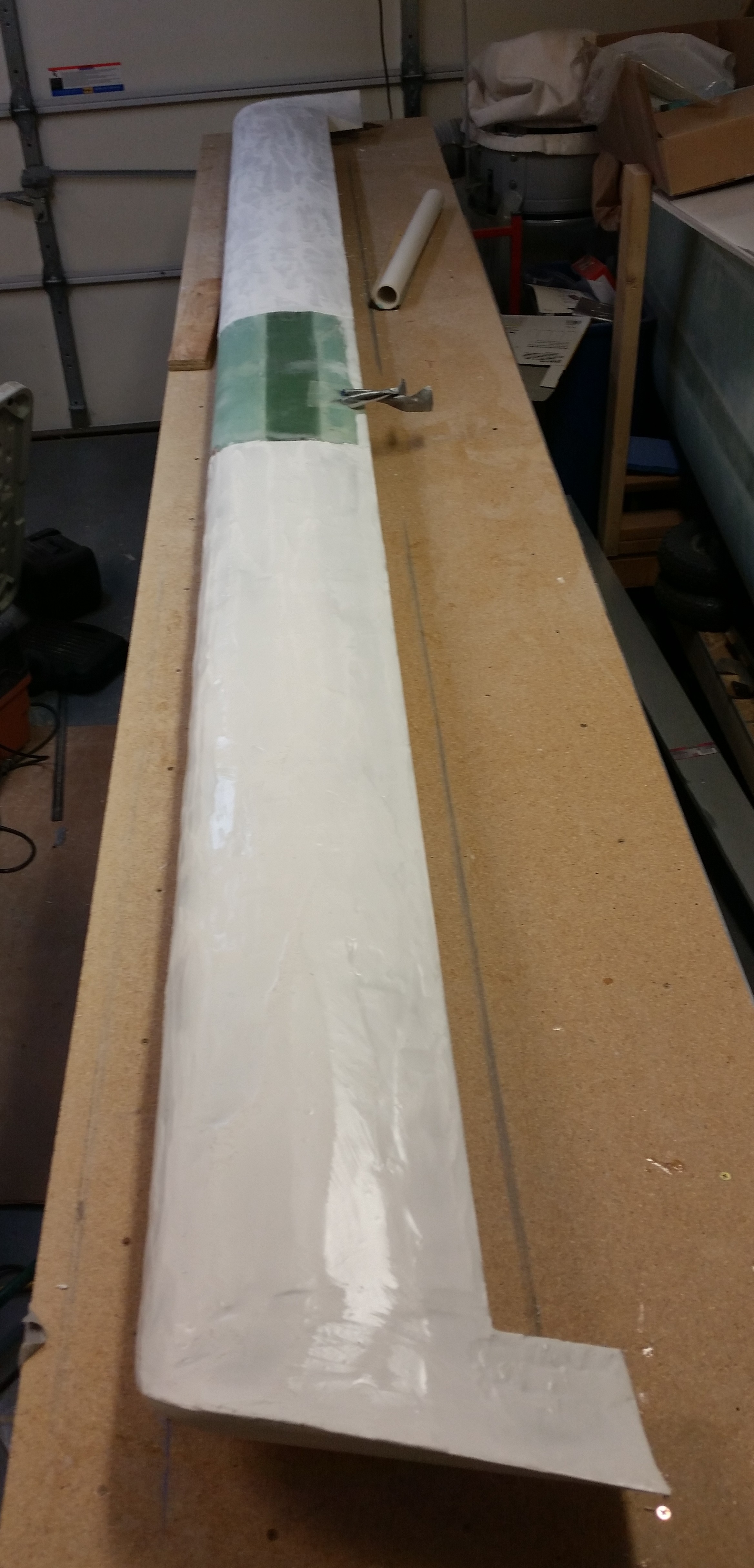
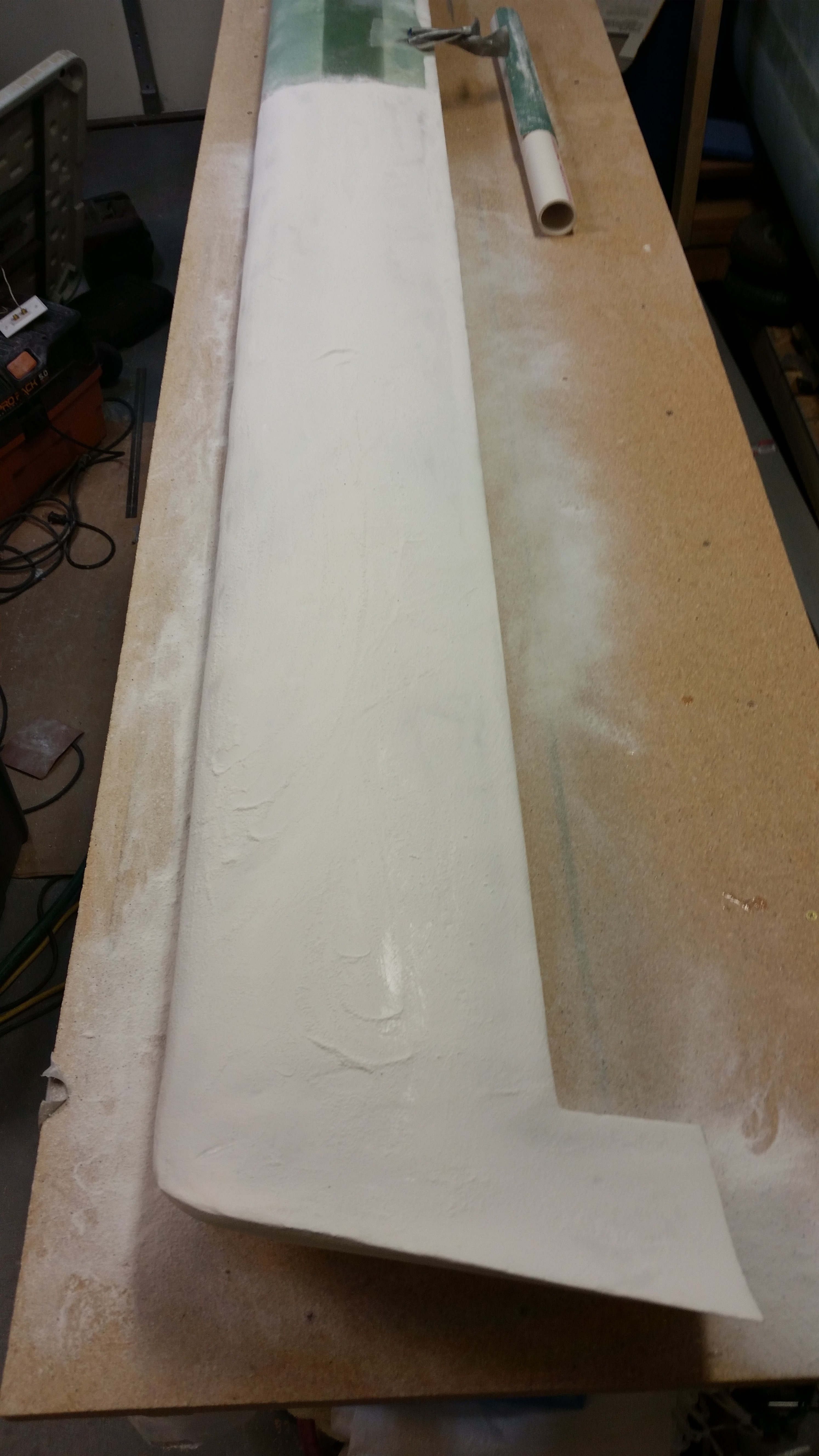
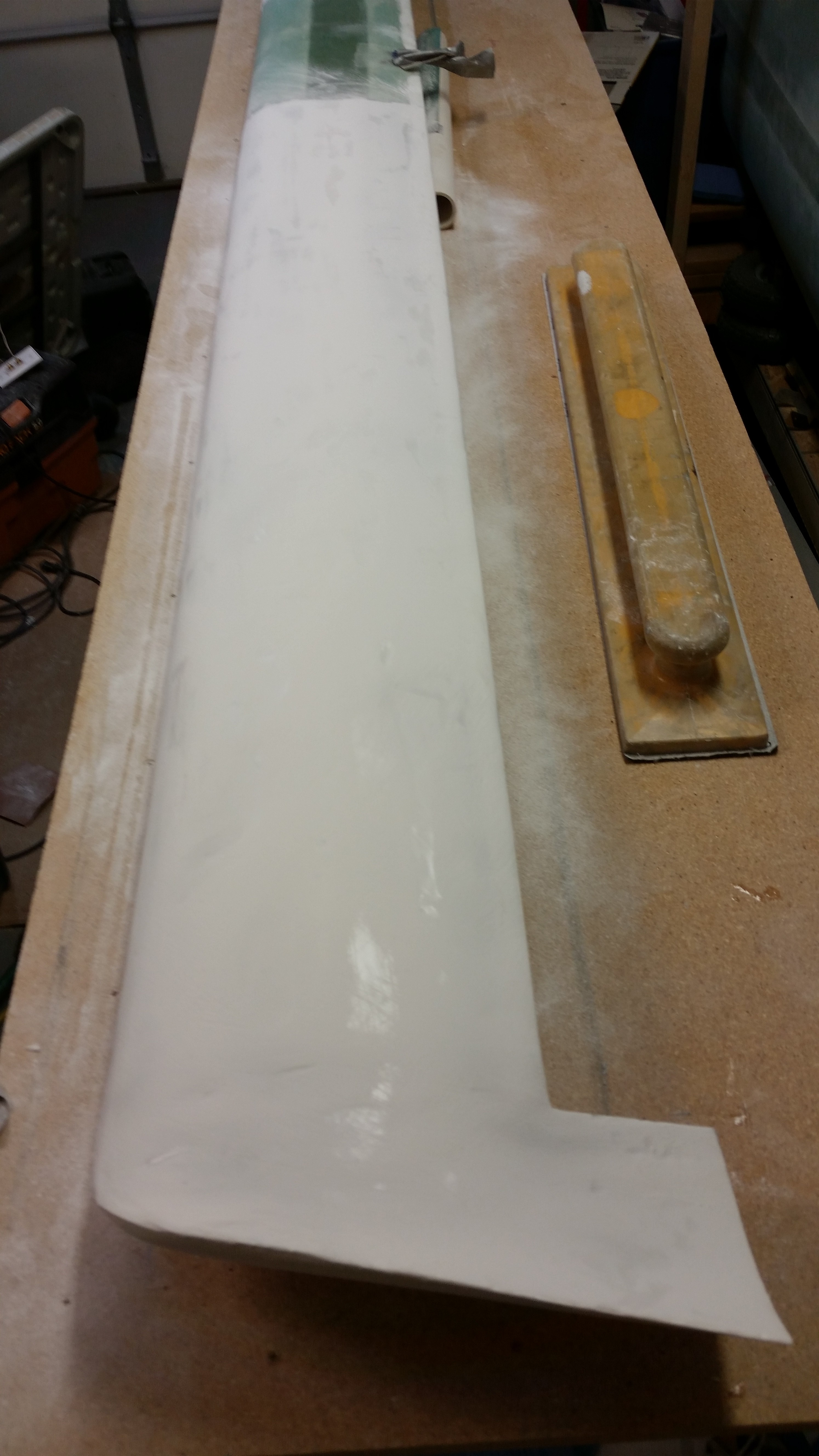
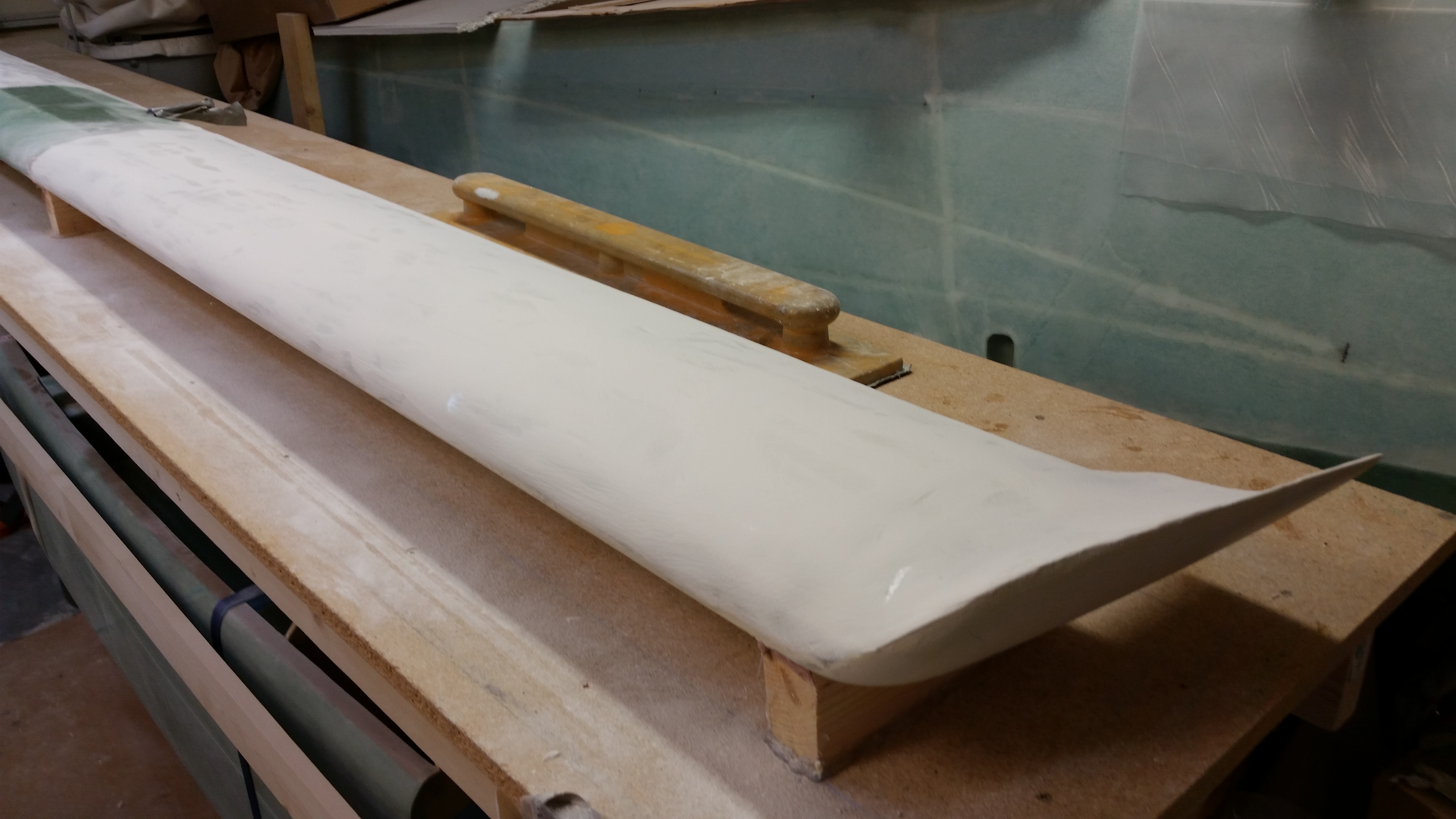
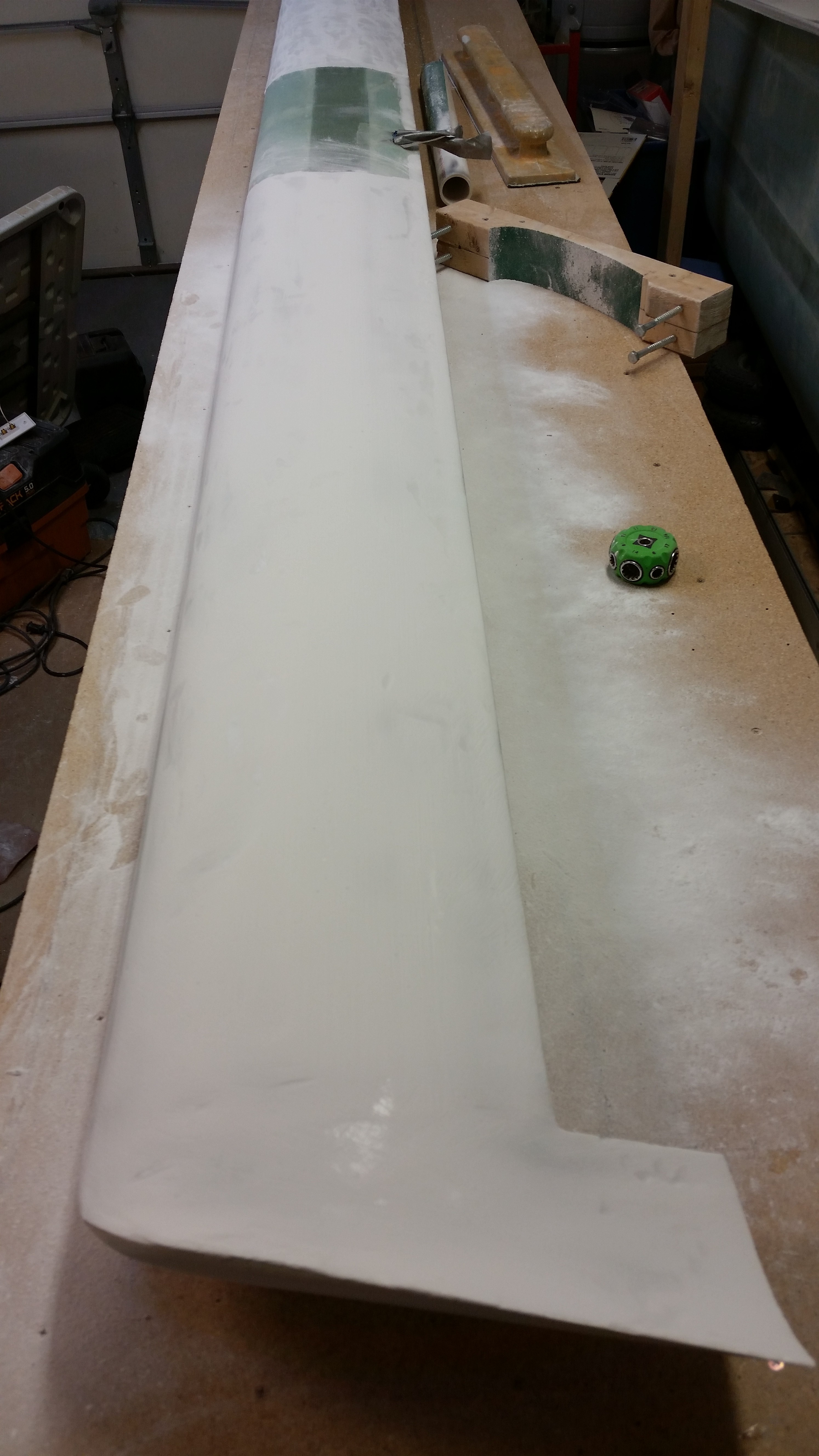
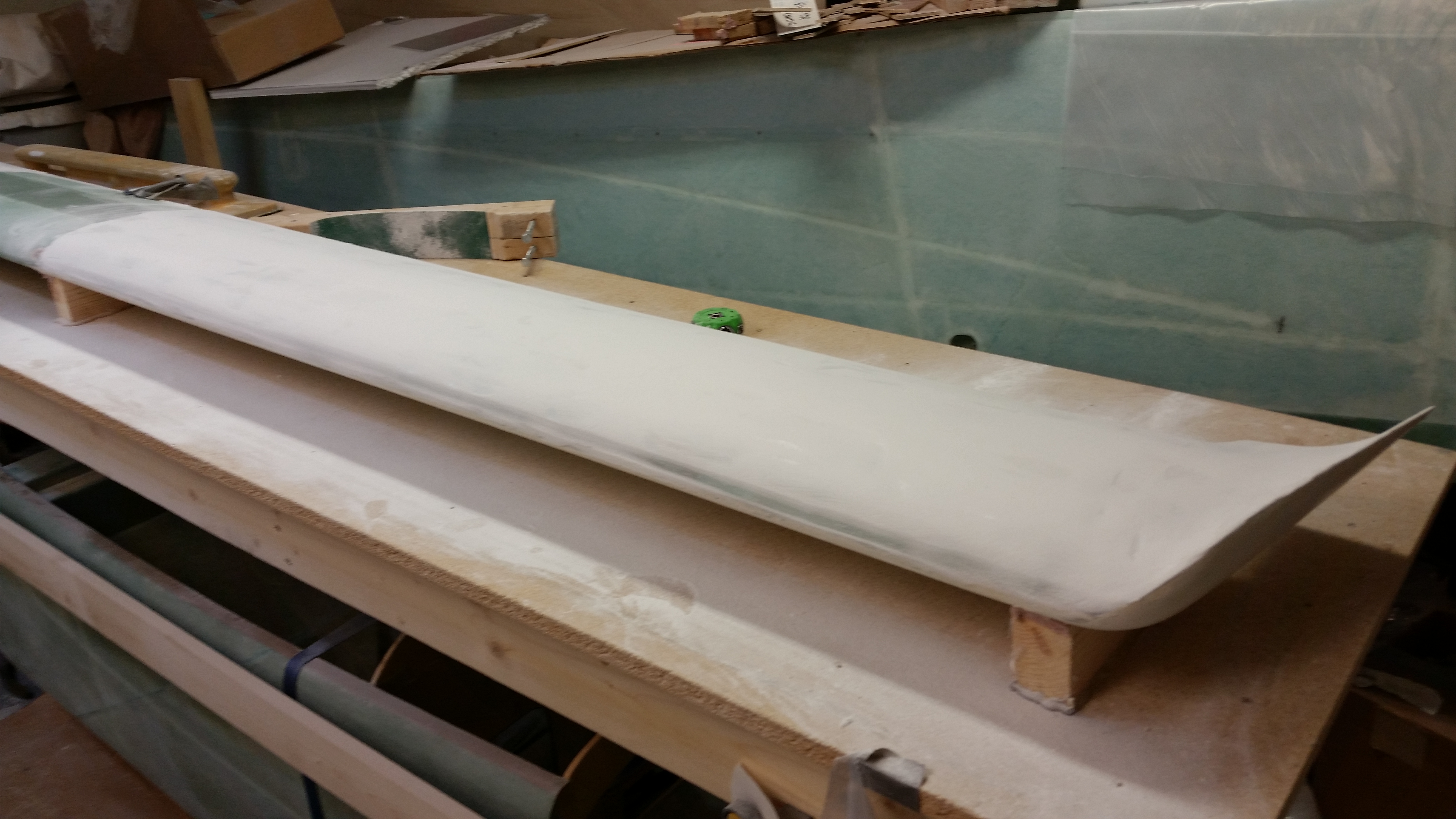
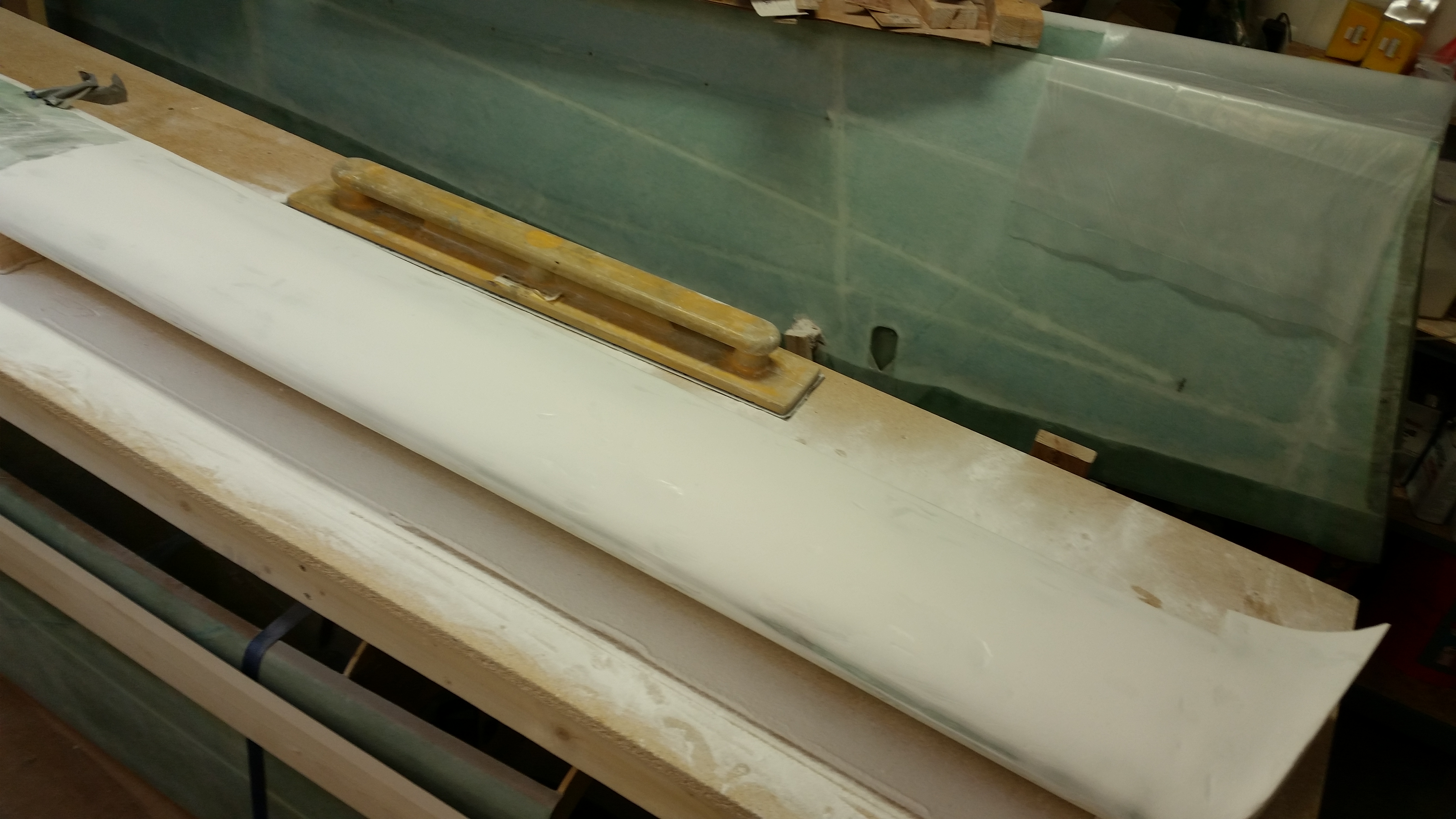
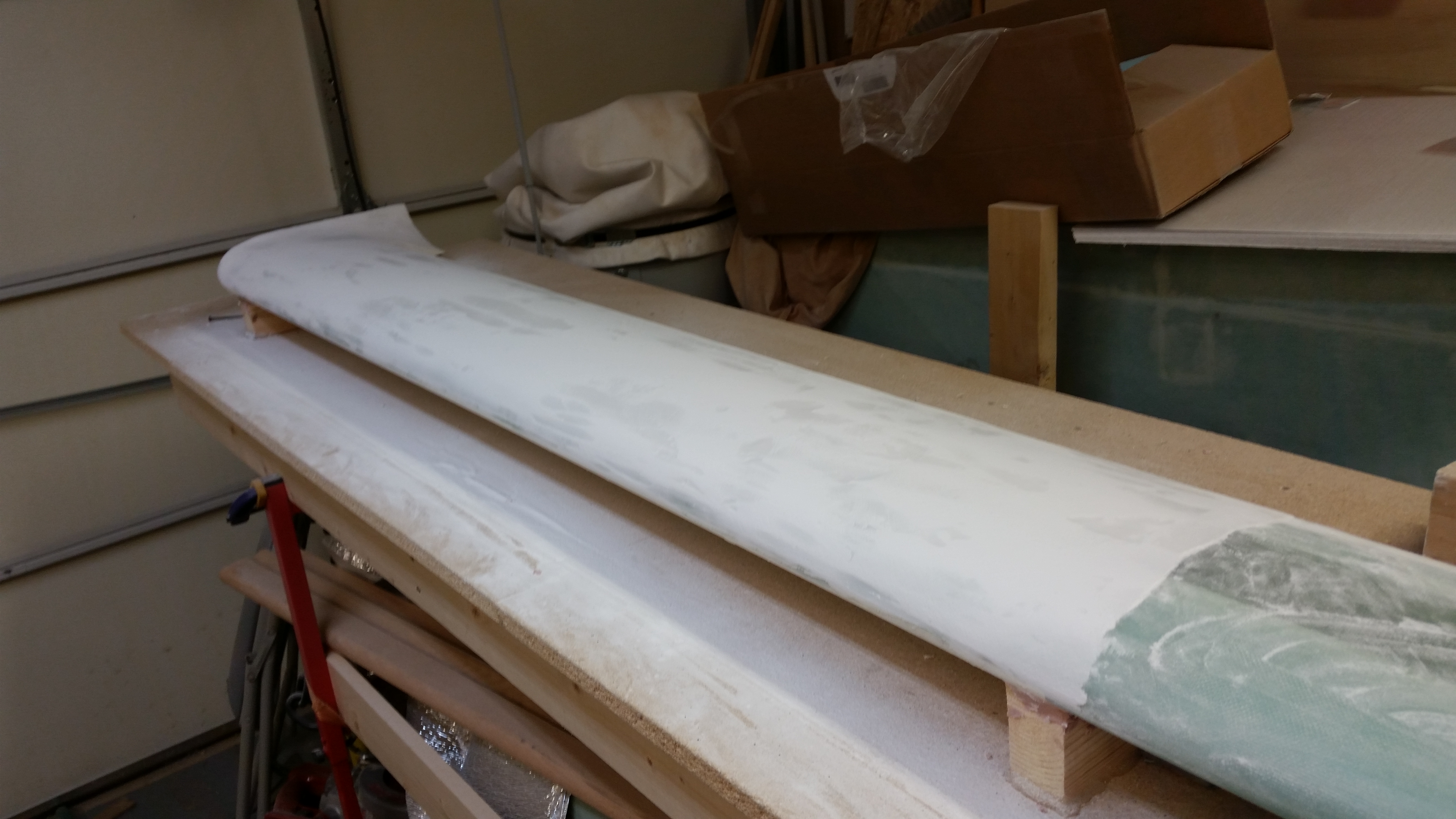
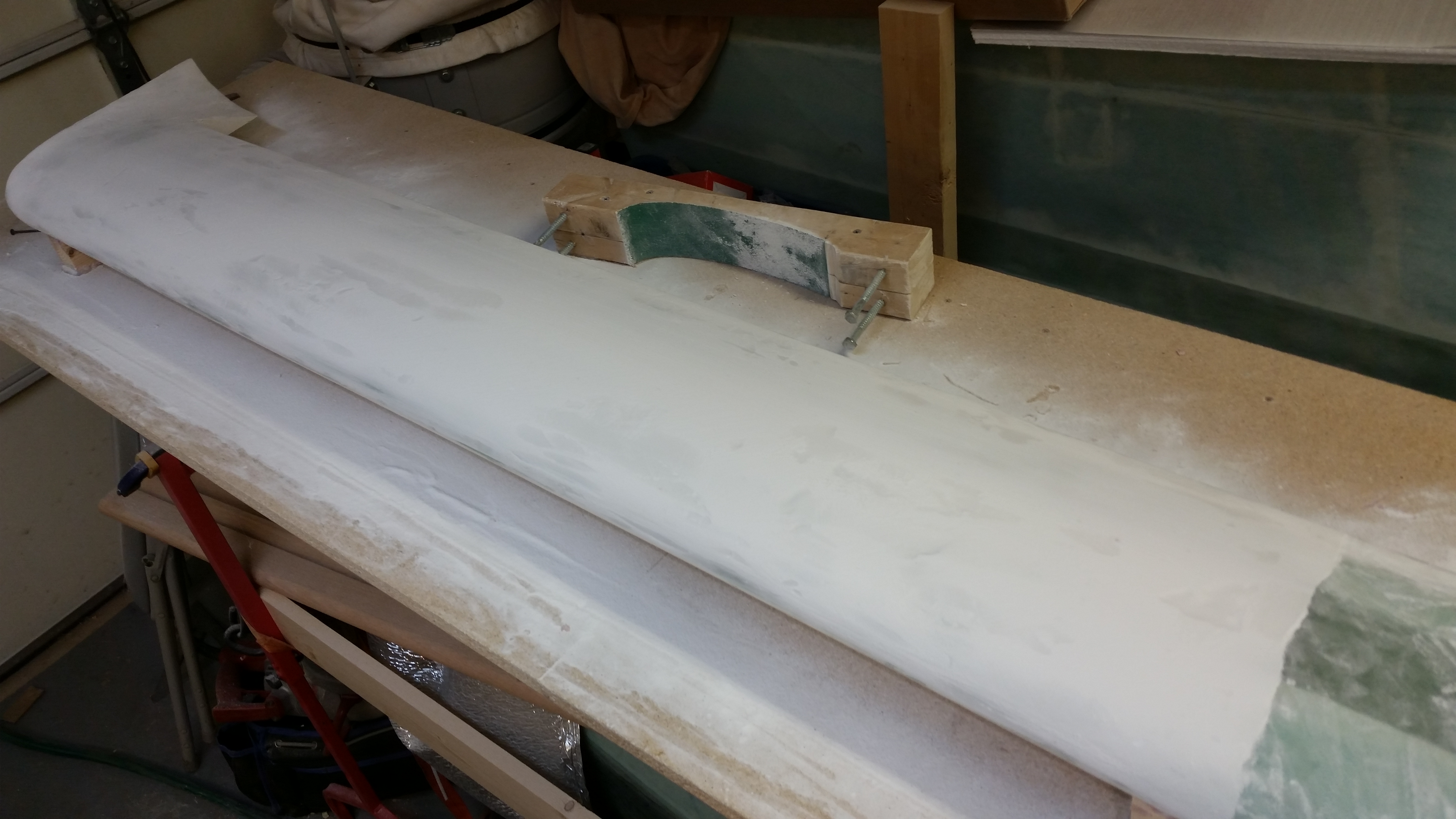
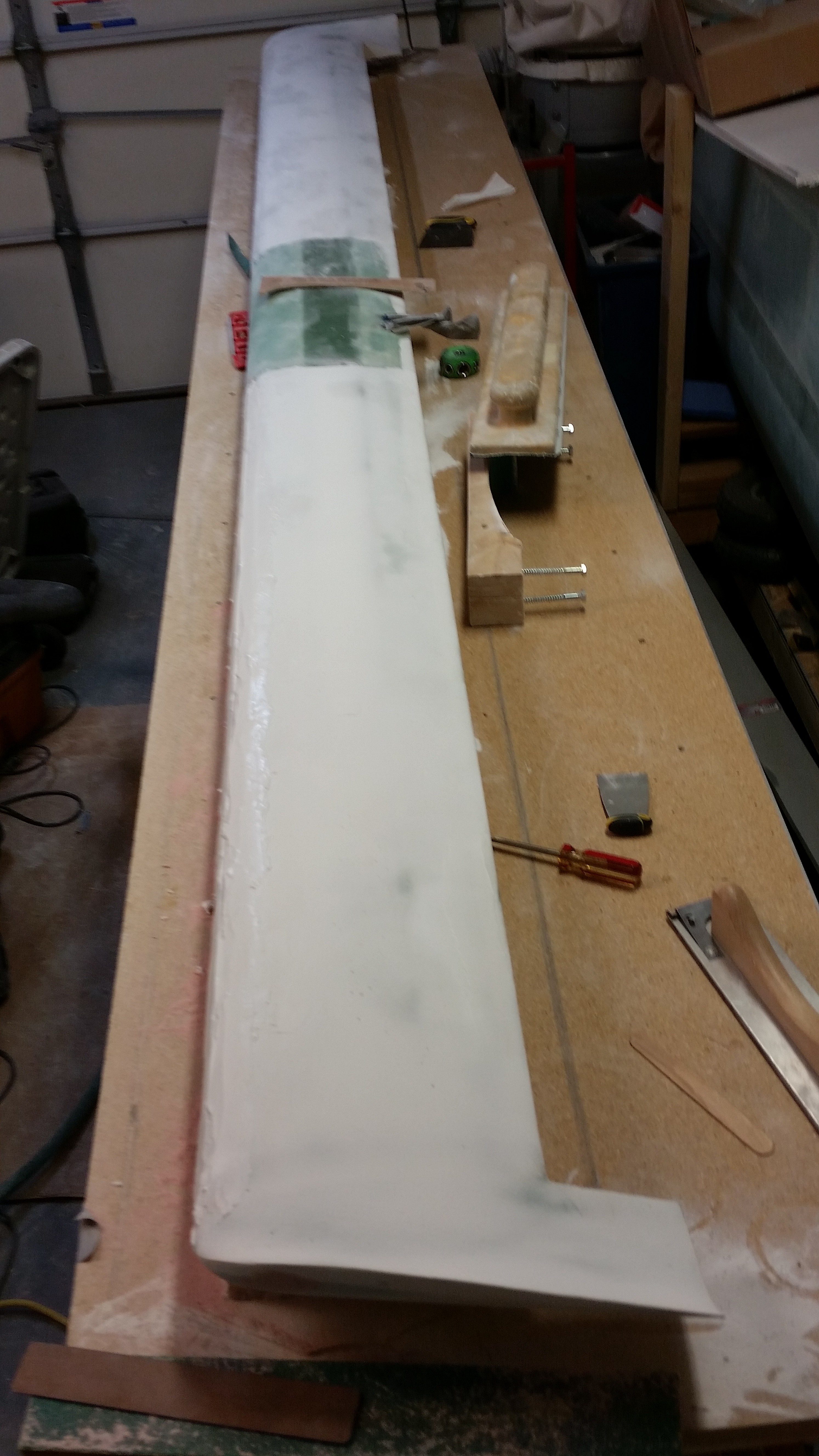
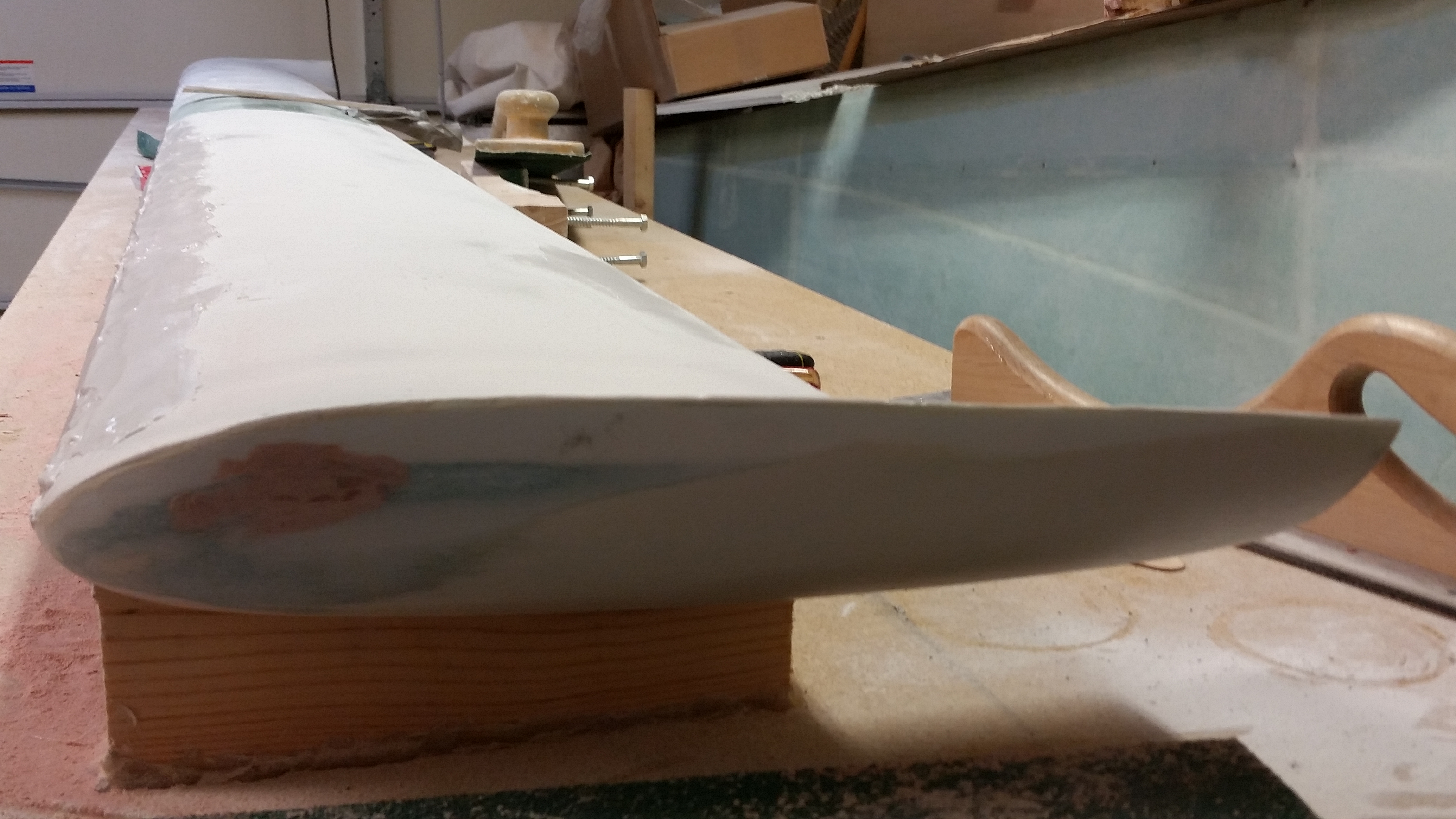
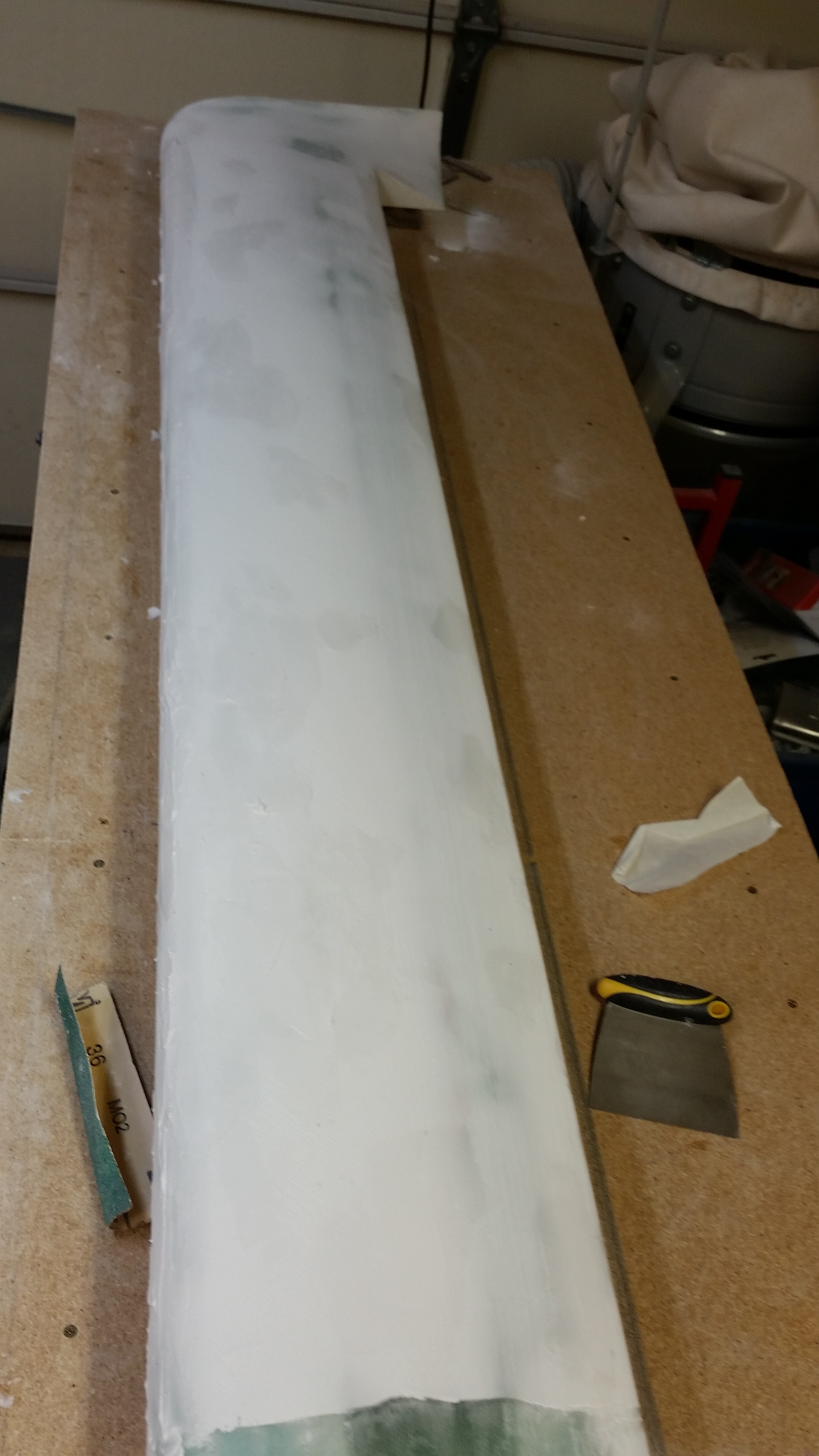
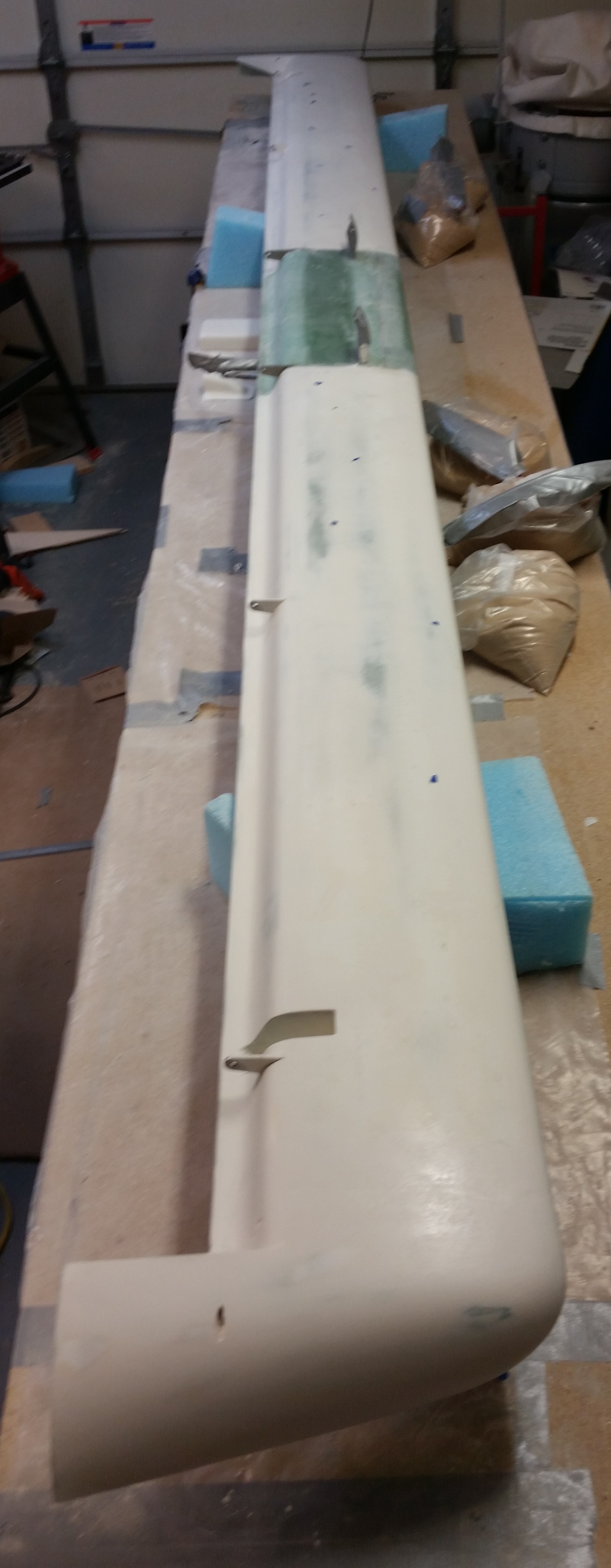
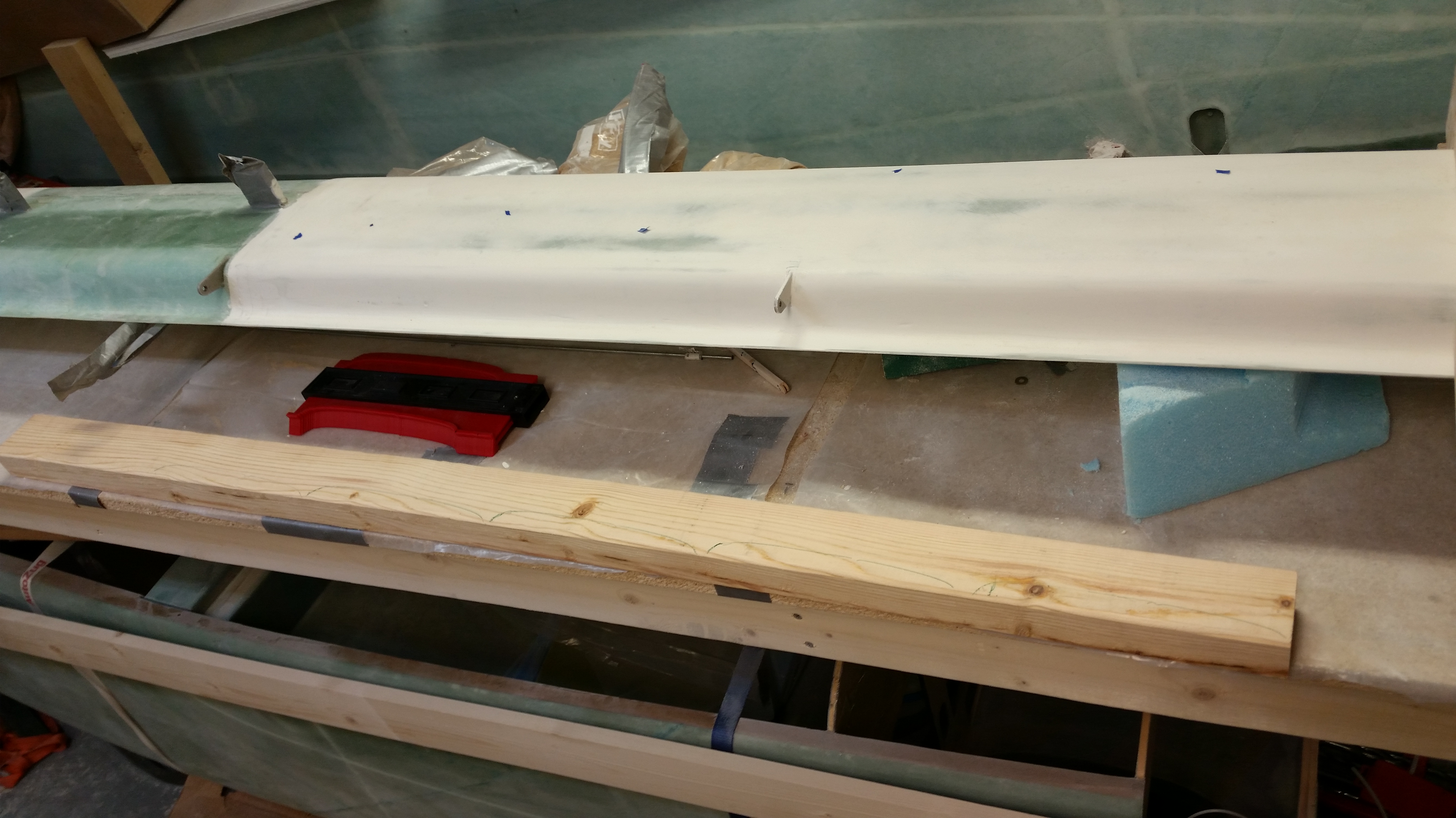
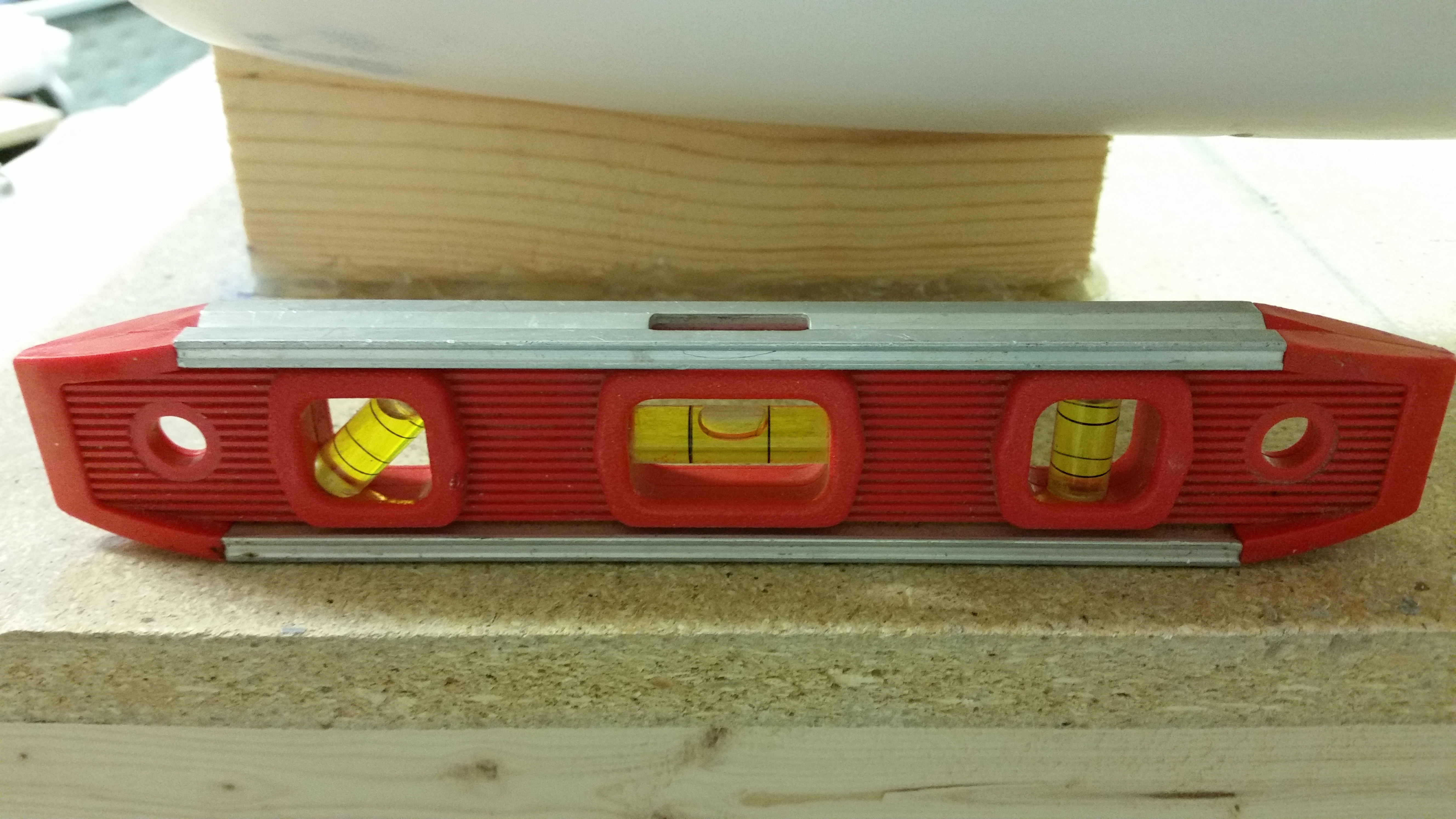
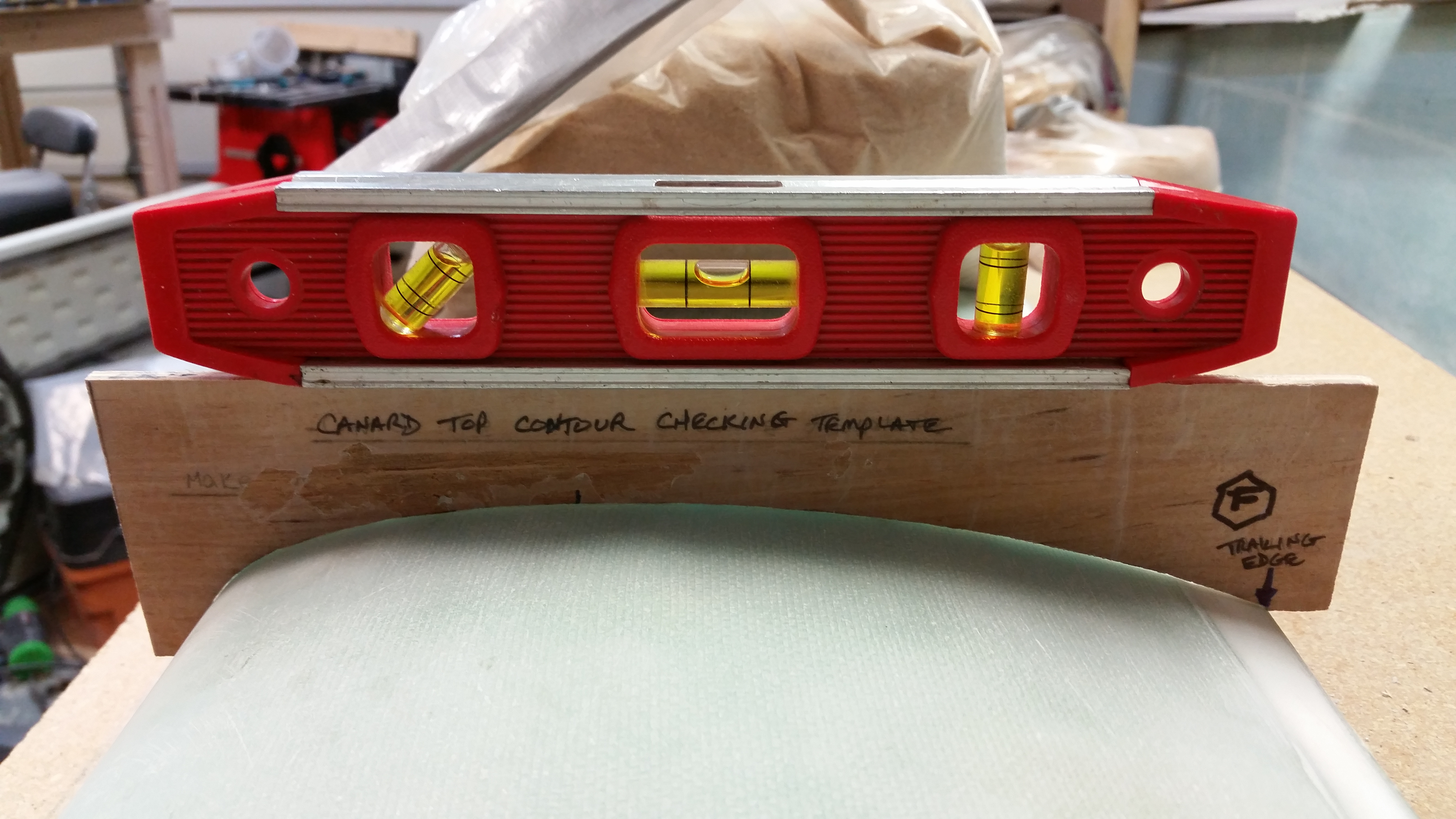
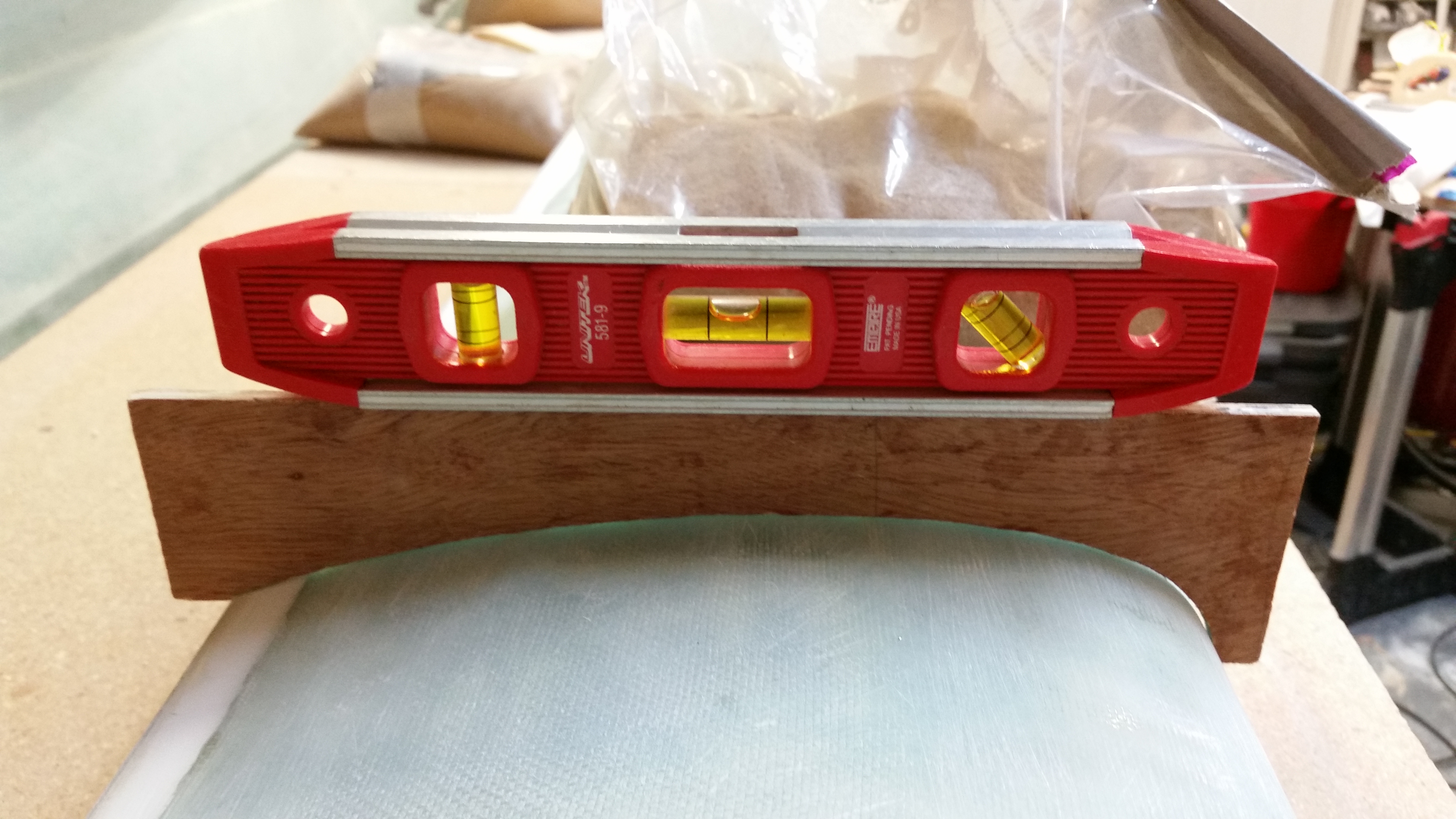
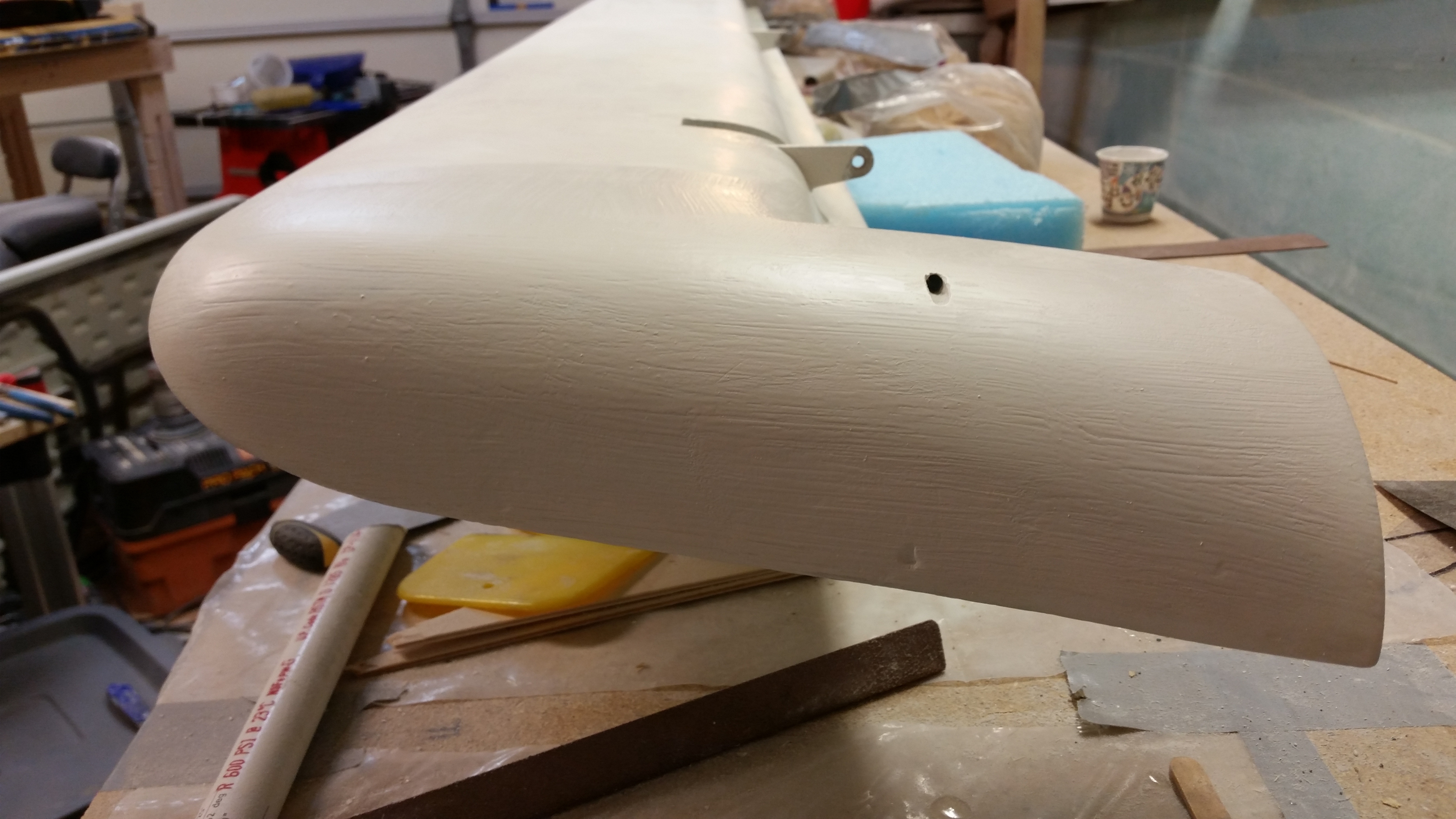
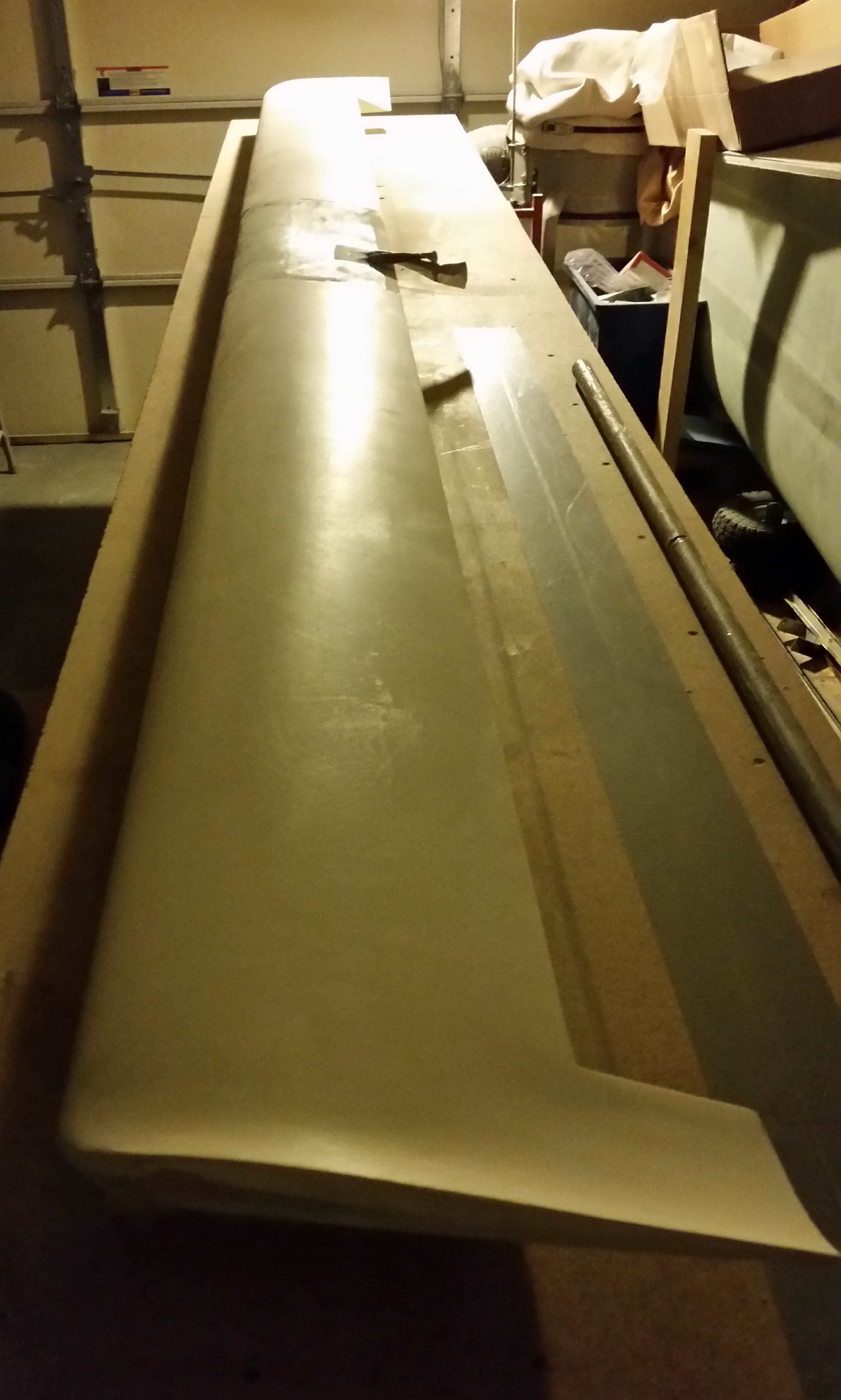
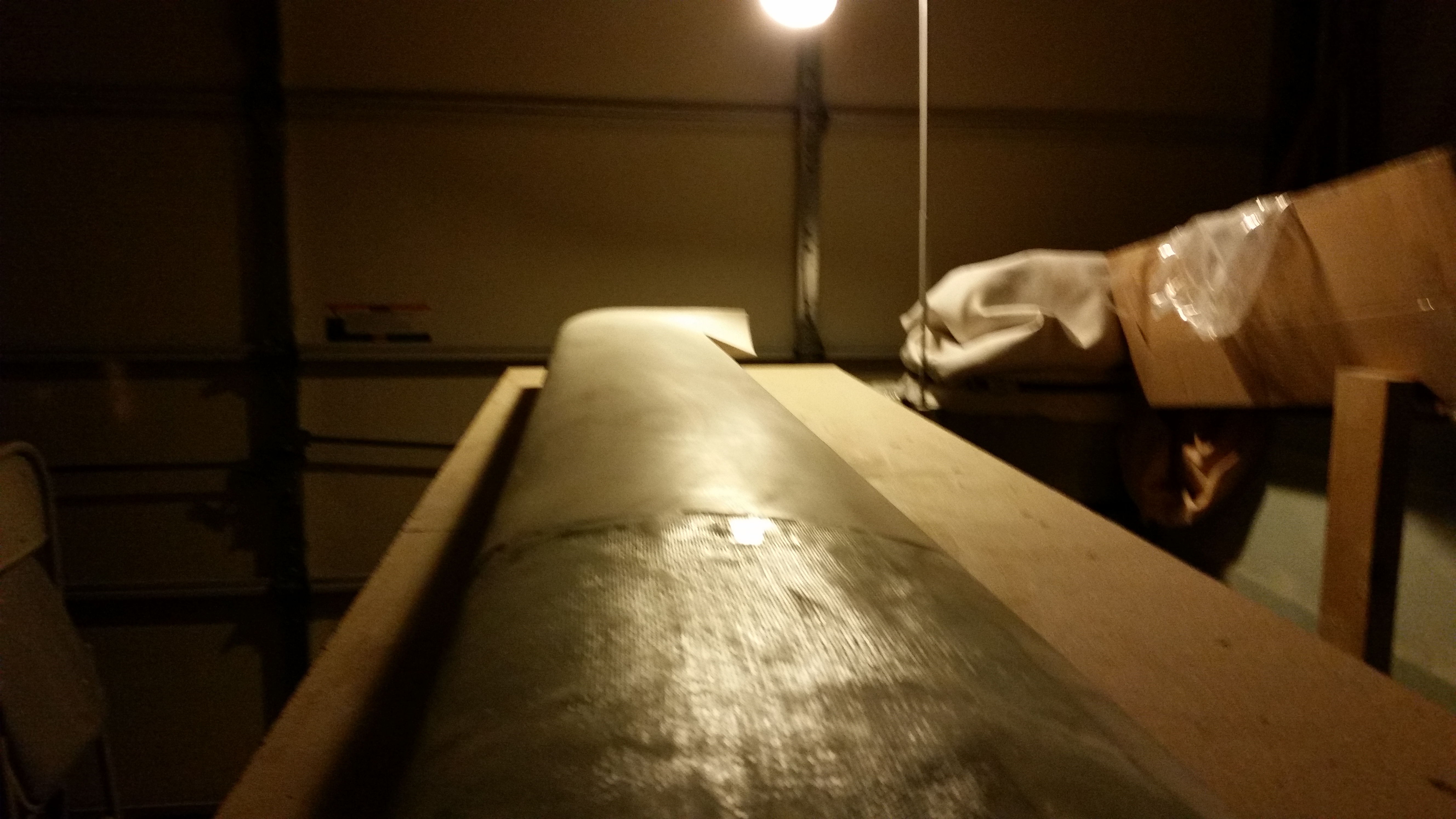
Finally, here are a couple of shots of the canard with nothing but a single light reflecting on its surface.  This provides a good view of the imperfections currently on the top surface of the canard.  As you can see, there are few minor imperfections –mainly simple & minor surface depressions– on each side of the canard top.

Canard surface view

Canard surface view

Tomorrow I plan on doing a final clean of the elevator tube, sanding down the surface, and then Alodining it in prep of micro’ing the elevator core to it.  I will also do a final sanding of the current primer on the canard top in prep of laying down a couple coats of the new primer.  I’ll then let the new primer cure 24-48 hours before giving it a final sanding.


Chapter 11 & 25 – Elevator DEconstruction

I started off spending a good hour, and 3 good long board sanding sheets, before I finally got the hint that although the primer looks cured, and feels cured to the touch, it’s not cured fully and that’s why my sanding sheets gummed up so quickly.  Argh!

So I quickly stopped that futile endeavor and started working on the elevator build prep.  My first step was to ensure the table surface was level for the elevator build.  I pulled out the über awesome aluminum straight board that I picked up in Germany to check the work bench alignment.  From the corner to about 60″ in I had just about 30 thou of sag in the table.  A couple of quick shims and everything looked good, straight and level.

Checking table surface straightness

I laid down some duct tape where the TE of the elevator will run on the table and then got to work deconstructing the elevator.

Right elevator

The first task was to remove the torque tube offset from the inboard side.

Right elevator

And then the elevator weight on the outboard side.

Removing outboard weight

After cutting the UNI plies at the base of the foam on top & bottom, I gave the weight a sharp rap, snapping it off.  Unfortunately it came off a little less gracefully (read: intact) than I had hoped for, but I think with some judicious application of flox it may very well work on the next elevator.  BTW, as you can see below, the UNI pretty much peeled right off the weight with a little effort, but not a lot.

Outboard weight removed

I then broke out my old friends, the NC-7s, to get a gauge of how they line up currently in the hinge tab slots.

NC-7s . . . Again!

I diced up a popsicle stick to make spacers for the current NC-7 gaps to replicate this on the next elevator when the core is mounted to the tube.  And yes, I’m allowing for the .020″ that comes into play for the skin thickness.

Acquiring NC-7 spacing

I set the current elevator in a good position for the next one as it gets constructed, and then made some alignment marks in a number of places to help ensure the elevator core gets mounted to the tube in the same configuration as the current one.

Alignment marks

This pic may be a tad fuzzy, but here is the underside of the elevator with its significant thin areas due to intense sanding over the delams that are root cause of all the issues I’ve had with this elevator.  Not good.

Surface disfigurement

I broke out the Fein saw and started cutting right at the junction of the elevator core and the elevator tube at a very shallow angle.

Starting removal process

I would track this cut for a bit until the blade broke through the fiberglass, then was able to move forward another few inches before having to come back to the surface and start the process again.  Here is the actual cut through the skin.

Removing elevator from tube

And here’s the entire bottom side of the elevator skin cut just aft of the tube.

Removing elevator from tube

I then moved to the topside and did essentially the same thing.

Removing elevator from tube

I had to put a metal rod into the top of the elevator tube to pry it gently from the foam core, but it came off with a good amount of pressure.

Elevator removed from tube

Here’s the elevator tube after I went to town on it with the Fein saw to knock off all the leftover foam, epoxy & glass residue.  I then filled up a PVC tube with white Vinegar and dunked the elevator tube into it about 3/4’s of the way up the tube (not shown).  I’ll let that sit overnight and see if it softens up the goobers on the elevator tube.

Tube after initial cleanup

Tomorrow I’ll continue my quest in finishing this new elevator, and the final sanding of the primer on the canard.


Chapter 13 & 25 – Rock the Casbah!

Or rather the canard!

I started out today by sanding the pure epoxy coat on the topside of the canard.  I began with 120 grit on the long board in a 45° pattern, both to the left and to the right.  After I sanded both sides with the long board, I then switched to 220 grit and wet sanded the epoxy finish.  This helped get the lower lying areas that should get filled with the high build primer.

Sanded down canard top

Here’s a shot of the right side.  For some reason the blog didn’t like the left side pic since I couldn’t load it.  Needless to say, it looked about the same.

Sanded down canard top

I then applied primer to the canard.  The shot below to the left is the first coat, and the right is the second coat.

First coat of primer

Second coat primer

In between priming the top of the canard, and watching football, I cut out the 2 phenolic support pieces that will be embedded in the NG30 cover for the AMP CPC connectors.

1/16" phenolic for gear actuator connectors

I also cut the 8 pieces of UNI for the new elevators that I will be rebuilding here in the next week.

UNI cut for new elevators build

In total I added 3 coats of primer.  I’ll wait until its cured tomorrow to block sand it.

Also, as I was prepping the canard for primer I happen to really note the color of the boat paint on the headrest GPS antenna cover and the ice shields.  It’s not a bright white, as the primer is not, so I’ll be calling Jamestown Distributors this week to figure out the way ahead on that.  I want the white on my bird to be as white as possible… not the 1970’s dull off-white stuff.  So I’ll be evaluating the paint further as I move forward.


Chapters 13 & 22 – More Electrical Stuff

Today –while the canard epoxy cures– was about research and getting reacquainted with my electrical system.  My specific interest was in figuring out what components, electrical & otherwise, that I was going to put into the nose.

Now I know a lot of my contemporary building buddies would whip up some awesome looking CAD diagram with exact dimensions down to 3 decimal places that looks like an engineer’s dream, but me being a former military “Powerpoint Ranger” and certified neanderthal, I simply added a slide depicting my thoughts on this matter onto the end of my ongoing notes for the nose build.

Again, this stuff is really just a mental thought jogger on what will most likely go into what areas in the nose, and get me thinking if there is any pre-actions or prep I can do as I build the nose.  Some of the components I ID’d will be in the nose area, but aft of F22: OAT probe, static ports, buss fuse housings, etc.  In addition, on many of the components I had to look up in my notes, emails, websites, install manuals, etc. to either confirm or research further why and how they were getting installed where.

Nose components

Now, I mentioned CAD earlier, so speaking of CAD:  The CAD program I was using to create my electrical diagrams was NanoCAD, as recommended by Bob Nuckolls in the AeroElectric Connection online forum.  This was a great CAD program for electrical diagrams primarily because A) it was what Bob used to create all of them, and B) it was FREE!  Unfortunately, my version of NanoCAD is no longer supported and apparently NanoCAD is now on Version 7, which costs a decent amount of money now to buy.

Well, no worries since I have TurboCAD, which I happened to purchase while I was in Tampa, Florida.  But I didn’t have it loaded up on my desktop so I ended up spending a good half hour loading up TurboCAD and familiarizing myself with its features before I could open up any of my electrical diagrams.  Why? Well, in a series of typical events, I had taken all the hardcopy printouts of my electrical diagrams down to my buddy Marco’s house while I was on leave from Qatar in March 2014, forgot them there, and haven’t been back to retrieve them yet . . . mainly because every time I go to visit him he puts me to work building HIS Long-EZ!  HA!  (Click here for the real story . . . )

Thus, to be able to make my annotations on my electrical diagrams on an actual sheet of paper, I had to be able to open the darn files to print them, which I am happy to report that I am now able to do.

In line with my reviewing my nose electrical components, my main preparation is in getting the nose gear actuator wiring sorted out to test it.  I had planned on going over all my electrical stuff today since the epoxy was still curing on the canard and also, in part, because my AMP CPC connector order from Mouser was scheduled to be delivered today, which it was.

I checked out all the goodies from Mouser and pretty much solidified my plan for the wiring & connections for the nose gear actuator system.

AMP CPC electrical connectors

Tomorrow I plan on a good final sanding of the canard top surface before I apply a couple of coats of primer on it.  In addition, I’ll most likely cut the UNI for the elevators and start planning out a refined elevator build schedule.  Who knows, I may even get the nose gear actuator wired up & tested out.


Chapter 25 – The canard riseth!

I finished the 4th application of pure epoxy around 2am, and after that I was tapped out.  I realize now I need to program in 2-1/2 to 3 hours between epoxy wipes on the surface being finished since 2 hours just isn’t enough.  Especially considering that each application of epoxy takes about a full half hour from start to finish to complete.

So, my total epoxy applications at this point is four (4) vs the planned five (5).  This actually works out fine because I can tell that I have some areas, the biggest being about 2″ wide, that will need a little bit more fill.  In addition, the simple action of repeated sanding –once the primary shape has been locked in with the epoxy finish– refines the surface finish when it finally comes to paint.  This may seem like an overly simplistic & obvious statement, but it is true and very evident during the sanding process.

Four layers of pure epoxy

Four layers of pure epoxy

Thus, my “new” (slightly modified) plan was to sand down the current epoxy wipe quite a bit to knock down the high points, level out the surface between the high & low spots, and bring the entire surface of the canard to a much tighter equilibrium finish elevation wise.  Then I would add another 2-3 coats of pure epoxy.

I started by checking the surface contour of the canard by not only focusing on the actual contour as compared to the bottom edge of the “F” template, but also by concentrating on the incidence angle that is being conveyed via seeing how the angle of the top straight edge of the “F” template matches the angle of the work bench.  In the picture below I have a really good top canard surface contour in addition to a spot-on incidence angle.

Profile looking good!

I then completed the contour check about every 4-6″ along the top surface of the canard. Below you can see the contour sanding lines I drew on the right-side canard top that denote the high points that need to be knocked down a bit for the canard surface to be better aligned with the contour checking template “F”.

To be clear, by cleaning up the contour profile of the canard (bottom side of “F” template) it had a direct effect of bringing the incidence angle into better alignment (top of “F” template).  As it stood, the areas where I marked the lines acted as a high point, or fulcrum if you will, where the contour template teetered upon one way or the other.  That being said, it was actually rather apparent that by reducing the middle high point, or “ridge,” that the forward part of the “F” template fell towards the LE and thus brought the incidence angle into proper specs.

Contour sanding marks

Here’s a shot of the canard after about an hour’s worth of sanding with the long board with 80 grit first, then 120 grit.

Sanded canard

I then applied 3 more coats of pure epoxy, waiting 2-3 hours between each coat.

3 final coats of epoxy

Here’s a shot of each side of the canard with the final 3 (additional) coats of epoxy.  A few hours after the final coat went on, I spent about 45 minutes pulling the remaining protective tape from the sides and cleaning up the TE, LE, and swoosh tip areas with a razor blade.  I got most of the gunk off these areas, but some still remains that will have to be sanded clean once I flip the canard for the final contour of the bottom side, with special focus on the LE.

3 final coats of epoxy3 final coats of epoxy

During one of the ~2 hour curing times between coats I ran out to a auto paint supply store to grab some glazing putty & wet/dry sandpaper to have on hand for this weekend.

Some finishing accessories

I’ll wait a minimum of 24 hours for the epoxy to cure before I do anything to the canard top.

Chapter 25 – Cory Bird is a Genius!

First off, before we get to Cory, as you can see by the pic below my new elevator cores arrived from Eureka CNC!  Thanks Steve!

Eureka CNC Elevator cores

After doing about an hour’s worth of research on some electrical topics for wiring the nose gear actuator, etc. I picked up my long board to sand yet once again.  (whew! … I’m not gonna get back on my soap box, but I still can’t imagine doing nothing but finishing for MONTHS on end!).

After about 15 minutes of sanding I was very close to the my final contour on the left hand side.  On the outboard third of the canard I’m maybe about 30 thou of inch (0.030″) too wide from LE to TE, but the profile is great.  And since I was closing in on the LE Bondo layer, and the inboard two-thirds looked really good, I called the left side around 97% good.  Any more sanding would have only gummed things up in my opinion, so I stopped while I was ahead.

Contour looking good!

The right side canard top surface didn’t come out as awesome as the left, but it still looked really good.  Since I had to do quite a bit of sanding on the LE area, I tapered it closer back to the shape where I was compelled to add another micro layer.

When I checked the right side with the contour profile template I got 3 near-perfect contours, 2 good contours, and one just ok.  Now, again, instead of sanding further and just compounding the problem, I decided to let the 5 coats of epoxy and 2-3 coats of primer take care of any minor surface deviations, and will backfill any major abhorrent surface irregularities that exist in the final finish steps.  Taking off a gross amount more of micro finish wouldn’t have done anything but make the overall contour profile even worse.

If I had to call it in percentages of optimum contour, I would give the right side a grade of anywhere between 85% and 89%, at it’s current state.  That being said, I’m confident that it will be at a grade of 95-98% of optimum contour by the time I’m finished.  Moreover, I’m really happy with how the top canard profile turned out!

Ready for epoxy!

I shop vacuumed the work bench and the top of the canard, and then taped up the bottom edges to control any overflow of out-of-control epoxy.

Ready for epoxy!

I then mixed up some pure West epoxy and spread it over the canard surface top starting on the right side.  It’s amazing how the epoxy wipes removes so many of the sins of micro finishing.  I’m not, of course, endorsing sloppy workmanship, but it’s nice to know that the divots, holes from air bubbles and depressions from not enough thickness in the application of micro will be greatly minimized, if not eliminated altogether, from 5 good applications of a very thin layer of epoxy.

Thus, again, Cory Bird is a genius!  And I’m glad he made this maddening process a heck of a lot easier . . .

Epoxy wipe #1

I then finished up on the left side.

Epoxy wipe #1

After the second application of epoxy to the canard top, I sanded down the first coat of final top coat paint on the headrest GPS antenna puck cover, and then sanded down and added the first coat of final white paint to the elevator outboard weight ice shields.

Now, to be honest I haven’t been blown away with the performance of this boat paint.  I don’t have negative feelings towards it either, but the jury is still out.  I may need to look at a better way of applying it, because on these parts I just used a cheap paint brush.  Thus, we shall see . . .

Painting a boat!

My plan for the rest of the evening is to get the final 3 coats of epoxy applied to the top surface of the canard.  In lieu of this, I won’t be adding any more to this post this evening.

Tomorrow, I’ll be prepping for the building of the elevators while the epoxy cures. Tomorrow evening I’ll most likely do a final sand of the epoxy covered canard and hit it with its first coat of primer.  And I still need to add some material to the right swoosh tip edge as well.


Chapter 25 – Inching forward…

To start, I cheese grated both LEs & the various spot fills on the canard surface shortly around midnight.  I have to say that I notice when sanding micro it seems to be tougher at the beginning when breaking through the shiny layer of epoxy that cures on the surface of the micro.  Once into & through that layer, the sanding tends to go a little faster with ever so slightly less pressure (ahem, not implying that a good bit of umph isn’t still required!).  Well, cheese grating seems to get to the point where that top shiny surface layer has already been broken through.  I’m hoping this is the case and that any difficulties that arise between sanding between micro layer #1 and added micro layer #2 is minimized by cheese grating.

An important realization that I had when I cheese grated the right LE is that the LE still wasn’t thick enough for my (and the contour profile template’s) liking.  It was late though & I really didn’t want to be up for another 30-45 minutes, so I left the adding of micro finish layer #3 until this morning.

After I got done cheese grating the top canard surfaces, I pried apart the two halves of the headrest by slowly & carefully inserting straight razor blades around the entire sides & back side of the edges where I applied the micro.  A big oops here and thank goodness I caught it in the green stage, because this would have been near impossible if the micro had fully cured.  I thought that the peel ply would make it so the two sides came apart with the typical & gratifying peel ply tear off, but this was a solid cure and turned the top & bottom “halves” of my headrest back into one solid piece.  Yes, if it ain’t one thing it’s another!  Ha!

That’s 30 minutes of my life I’m not getting back!

Headrest - edges micro'd

This morning I added more micro to the right side LE.  Again, we’re talking if I get 1/16″ added filler depth after sanding (which is always the trick! that damned sanding inexplicably tends to remove the stuff you put on in the first place… bewildering!) then I’ll be happy.

Right side LE re-micro'd

I also noted after checking the canard surface with my contour profile template that the aft side of the left side canard has just a bit of daylight, so I skim coated with micro the entire left side aft canard about an inch forward of the LE in about a 3″ swath.  Here, anything that provides a little extra surface depth is golden since I’m not overly concerned about this area.  But since I’m contending with other areas on the top of the canard, I might as well take the opportunity to tweak this area as well.

Left side TE strip re-micro'd

Yesterday, when I wrote up my 3×5 card to-do list (or “cut sheet”) for finishing the top of the canard, I added tasks that I can do in-between the epoxy wipes during the 2-2.5 hours it takes for the epoxy to set up for the next coat of pure epoxy.  These are those small, gotta do tasks that SHOULD get done eventually, but don’t hold a lot of weight in actually getting the plane built, or at a minimum, have anything to do with the current chapter at hand.  Of course there’s been a myriad of these pesky tasks that require completion: from adding the click bonds to the wing root rib, to micro’ing the edges of the headrest, cutting the 4130 engine mount extrusions, etc.

Although clearly I have not yet started the epoxy wipes on the canard, since I have to wait for the freshly added micro layer #3 to green, I started in on my list of these tasks… the first one being to sand down the base of the rollover on each side to clean up the irregular surfaces & shoot it with primer again.

Sanding round #1 I used 100 grit paper on each side, then did a final round #2 sanding with 220 grit paper.

sanding rollover base

sanding rollover base

I then cleaned up the freshly sanded surfaces with Simple Green, took the rollover assembly outside and shot the sanded areas with 3 coats of the same Rustoleum gloss black primer that I used previously.

3 coats of gloss black primer

With my canard micro still not “greened” yet, I spent a good 45 minutes cleaning up and organizing my garage work shop (much needed, and yes, on the to-do list!).

After my cleaning spree, and with both the rollover assembly and the re-micro’d canard still curing, I decided to test out my boat paint on the headrest GPS antenna puck cover.

Painting GPS antenna cover

I duct taped the antenna cover to the top of a paint spray can and then brushed & tipped on the first coat of white boat paint.  This will be the first of a few test applications I use to see if I’m going to move forward with using boat paint, or at least this brand of boat paint.

Painted GPS antenna cover

Finally, the new micro was at a good green stage to cheese grate it.  I spent a good 20 minutes cheese grating the LE edge area and then I quickly hit the left-side TE swath that I had applied at the same time as the right-side LE.

If you look closely in the pic below, you can see that the swoosh tip has some Bondo on its ridged edge.  I applied this shortly after micro layer #3, but forgot to snap a pic of it, which I rectified below.

Right side LE cheese grated

Here’s a shot of the bondo on the swoosh tip ridge edge.  It needs to be built up just a hair to A) cut a near straight line profile-wise from front to back since it has a very slight dip, and B) the ridge needs to be just a tad bit more pronounced (read: higher) to better match the left side ridge.

Right swoosh tip edge build up

Again, I know Bondo is MUCH heavier than micro, so I’m using it very sparingly, but I know from experience that it’s some tough stuff.  As you can see below, just from the very initial sanding, that I’ve knocked off about 80% of the Bondo that you see above.  Once I get the ridge set, I’ll probable follow up the Bondo with a final application of flocro (micro & flox mixed together) to smooth out any irregularities and add to the strength of the ridge.

Right swoosh tip edge build up

As I was just finishing up with the cheese grating I heard the distinct sound of my neighbor’s Harley.  I haven’t seen my neighbor Dave around in weeks, and with my bike sitting in the driveway at the ready, I ended up going on a scoot for a few hours with Dave.

Tomorrow I plan on actually getting the top of the canard finished to its final contour & shape, and then get the 5 coats of epoxy squeegeed on.  Also, as an update, the original FedEx ETA of today for my Eureka CNC elevator cores has been slipped to the right one day until tomorrow.  No worries since I obviously need to get this canard finishing complete to clear up workbench space to build the elevators.

Chapter 25 – Sometimes you’re the hammer…

. . . yep, and sometimes you’re the nail.  Today, I was the nail.

Since the weather was good, I decided to wash off all the sanding dust off my motorcycle and then cut the 4130 steel engine mount extrusions.  Now, as far as I know you can’t buy 1″ 4130 angle “iron,” so I bought 1″ x 1″ x 1/8″ square tubing a couple of years ago for the engine mount extrusions.  I figured I would merely cut the tubing along opposite corners and Voila, I would have my L-shape angled 4130 pieces.

About 6 months ago I called a local steel company and asked them how much it would be to have them cut these for me. They said they didn’t do it and referred me to a local machinist, who wanted nearly $200 to cut the damn things.  Well, a couple of months ago a friend of mine’s elderly father unfortunately passed away and she had the small table saw below that she very graciously gave to me.  Since it was a little beat up and since it’s much more inexpensive than my larger portable table saw, I would use it with a metal cutting blade to cut these 4130 square tubing engine extrusions.

Prepping to cut engine mounts

Here’s the square 4130 tubing for the engine mount extrusions.

4130 Engine Mount Extrusions

4130 Engine Mount Extrusions

Ahh, the well laid plans of mice & men!  Unfortunately the blade would flex to the side under the pressure of the hard 4130 steel so it wouldn’t really cut the corners cleanly.  I played around with it for about 15 minutes before finally realizing it was a lesson in futility.  With the corners thinned a bit, I grabbed my Dremel and tried to cut it freehand.  Well, that’s the hardest 4130 steel I’ve seen because by the time I got from one end to the other my Dremel cut bit had disintegrated.

Ok 4130 square tubing!  You won round #1, but I’ll win in the long run!  Ha!  With that, I moved on to more important build tasks at this point in time.

So early in the morning, around 2:30 AM I went down to the work shop to “cheese grate” the micro finish on the canard.  Well, the micro hadn’t fully “greened” yet, so it was still a bit gummy.  I did what I could for about a half hour, but then gave up and went to bed after setting my alarm for 4 AM to get another half hour of “cheese grating” in.  To be honest though, I’ve been exhausted from sanding for hours on end & building the fuselage dolly. Bottom line I slept right through that alarm and missed the “green” state of my micro, so it was nice and cured when I started this afternoon.  You can see that the right side is much more cheese grated than the left.

Sanding Canard Micro Finish

I knocked down the high wave tops of cured micro with the 2″ PVC pipe with 36 grit sandpaper, which is what I used to shape the swoosh tips.  After about 10 minutes with the PVC sanding tube, I moved on to the long sanding board with 36 grit mounted on it.  Again, I sanded for about 10 minutes with the long board.

First round sanding with tubeLong board on deck!2nd round sanding with long board


Here’s a shot of the left side of the canard after I sanded it with the long board.

2nd round sanding with long board

After I got the contour somewhat in line, I switched to the contour sanding block with 36 grit sandpaper.

Loading contour sanding block

And here’s a couple shots after I did about 3 good passes (~5 minutes) with the contour sanding block.

Round 3 - Contour sanding block

Round 3 - Contour sanding block

I then switched back to the long board, using it primarily for the rest of the sanding of the left side top canard surface.  Now, I did do a little hand sanding on the top of the swoosh tip and a did a few more quick passes with the contour sanding block.  Below is a couple more shots after the major sanding on the left side was complete.

Round 4 - Back to Long Board

Round 4 - Back to Long Board

I then started in on the micro finish on the right side of the canard.  Since I had done a fair amount of cheese grating on the right side, I started with the long sanding board.

Sanding right side - Long board

After working the long board for a good 10 minutes, I then switched to contour sanding block.  Interestingly, you can see in the pic below that the main contact point for the contour sanding block on the right side was just forward of the TE. Now, I will say that although my canard looks spot on when I sight it by eye, and even run a string on the edges, I think there’s a very slight twist to my canard.  Nothing major, but enough to throw some twists (pardon the pun!) into my canard endeavors.

Round 2 - Contour sanding block

I then checked the top of the canard with the original contour checking template.  Now, in the pic below you probably notice a pink LE.  Before I took this pic I was checking the top canard profile and kept seeing a gap at my LE, in part caused by my contour sanding block digging into the LE edge a bit.  It did get a little of the glass, but not nearly enough to require any glass repair, but I did what something tougher than micro as a foundation so I slathered on a thick layer of Bondo onto the outer 2/3rds of the left side LE.

Since Bondo cures so quickly, after working for a bit on the right side I came back and quickly sanded the Bondo.  Now, I know Bondo is heavier, but the resulting sanded layer averages around 30 thou (0.030″) thick.  Like I said, it’s enough to give a little depth and a little harder base that can’t get sanded off so quickly.  I’m really seeing that both the trailing & leading edges can go uglier fast, so due diligence to these areas is a must.

Checking contour profile

I then violated one of the laws of the finishing composites by adding a second round of micro to fill in the low points on both sides (left/right, top) of the canard, and also slather a bunch on the LE on both sides to build that up to better get the plans LE shape as close as possible.

Second round of micro

Early on I was aggressively shaping the left outboard/bottom swoosh tip when I got to glass, and broke through to the inner layer of glass.  With the glass thin at this point, when I mixed up the Bondo, swabbed some on that area too to beef it up just a bit more.

Bond on swoosh tip thin spot

Here’s a couple shots of micro round 2.

Left side LE - Micro over bondo

Right side - remicro'd

Of course I mixed up too much micro and expecting at one point that this might be the case, I implemented my ancillary plan and Dremeled out the foam on the edges of the headrest halves.

Removing headrest edge foam

Here’s the micro applied to the headrest edges.

Applying micro to headrest edges

I then peel plied the micro, closed & locked the headrest and then weighed it down to compress the micro as best possible.

Peel plied then weighed down

I’ll most likely cheese grate the second application of micro later this evening, but for the sake of expediency I’m going to go ahead and post this.  I’ll continue to focus on the canard over the next few days, but I will start working on the new elevator cores as well.


Chapter 25 – Making it to the top!

I spent the first half hour this morning finalizing my wire tracking & matching endeavor on the EZ Noselift Actuator wiring harness.  I got down to 2 unclaimed wires, but wasn’t sure & couldn’t tell by the wiring diagram if they were supposed to be spliced together, although I suspected they were.

Crazy wires

I fired off a quick e-mail to Jack Wilhelmson to verify a few things on the wiring and he e-mailed back shortly later to set me on the straight & narrow path!  So all is good thus far in the wiring department for the nose gear actuator.

After I got everything straight with Jack, and as I was waiting for his e-mail, I was finishing up some research on Amp CPC connectors on Mouser.com.  I ended up calling Mouser to confirm that I was ordering the correct stuff.  After cracking the code on the various pins & sockets for the Amp connectors, I fired off my dorder to Mouser for Amp connectors to replace the Molex connectors currently used in the nose lift actuator system.

After I got the nose gear actuator system’s electronics straightened out, I started back on my quest to get the canard finished.  I ended up sanding the bottom of the swoosh tips, the area just inboard of the swoosh tips and the 2 outboard elevator hinge pin areas on each side.  Quite amazingly, by the time I was done on the bottom of the canard, 3 hours had flown by.

Sanding last stage of primer

The corners where the canard end caps (swoosh tips) meet the TE take a while to sand and are time-busting PITAs!

Sanding last stage of primer

After I got the newly primed areas sanded on the bottom bottom of the canard, I went to work on mounting the canard right-side up to finish the top of the canard.  To be clear, my buddy Mike recommended I wait so that I can finish the middle nose fairing on the canard at the same time, but I may utilize an alternative center canard fairing which would negate the standard plans canard nose fairing.

In addition, as I’ve mentioned before (and I have thought about this a fair amount while I’m finishing the canard):  As much time as it takes to finish the surfaces of this plane motivates me even more to finish the parts I can in prep for paint so that the finishing of all these parts don’t come due at one time!

I ended up deciding to use 2×3 blocks under the canard to hold it in place while I finish the top.  I marked the lower curvature profile of the canard in 5 consecutive spots on a 5′ long 2×3.  I used the lower contour profile as a template and after marking the 2×3 I cut out my mounting blocks.

Prepping canard supportsPrepping canard supports

Here are the blocks ready to be hot glued to the work bench.

Setting up to finish top of canard

I ended up only using 4 of the 5 mounting blocks, and I’m mounting them in the middle of the canard, where finish won’t matter, and at the ends where the swoosh tip junctions meet the canard ends, since these areas need some work on the transition anyways.

Hot gluing support blocks in place

I then measured the angle of the table again on each end.

Checking work bench angle

And then matched the surface angle of the canard to the table at each end so that it is aligned, to ensure I’m sanding true while using the contour sanding block.

Checking canard mount angle

Checking opposite side canard angle

I then broke out the Bondo and set the canard to the 4 mounting blocks.

Bondo'ing canard in place

Here’s a close up shot of the canard Bondo’d to the mounting block.  Note the hot glue holding the block to the work bench.

Bondo'ing canard in place

This is the last time the canard will be in its raw form!

Ready for micro!

And here’s the top of the canard after I applied the micro finish.

Micro finish applied

After the West epoxy micro cures for 2-3 hours and is in its “green” stage, I’ll cheese grate the surface to knock off all the high points and get the surface cleaned up.


Chapter 25 – Yep, Sanding Canard

Since there was a good chance of rain earlier today I decided to get the wood for the table platform brackets cut.  In addition, I wanted to get the saw out of the garage and back into the shed behind the house.

Figuring that there wasn’t going to be a lot of visual storytelling going on today, I snapped this picture to show the wood-cutting process.

20151101_115008

My original plan was to get the bottom of the canard sanded and then West micro finish spread on the top of the canard.  However, I ended up spending almost 3 hours sanding down the primer on the swoosh tips, inboard canard tips area, and the two outboard hinge tabs.

Once I fished sanding the first round of primer, I applied a fresh coat of primer on the areas I just sanded.

I then went to dinner and upon returning home I found that the primer in the cup was still flowing out & very wet, so I used it to apply a final coat to build up the total primer thickness as much as possible.

20151101_152803

After cleaning up after the final primer application, I went upstairs & reviewed the wiring diagram for Jack WIlhelmson’s nose gear actuator.