Chapter 25 – Main gear epoxy wiped

With a clear blue sky, albeit much cooler than the last couple of days, I pulled the fuselage outside to finally sand down the main gear legs’ micro refill for what would be the final time before epoxy wiping them.

Here’s the fuselage outside along with the right wing.

To reiterate the woes of winter building, when I pointed my phone to take this shot it was 3:59 pm.  When I looked at my phone afterwards it had flipped to 4 pm on the spot.  That is the sun peeking through the trees on the side of my shop.  Clearly not a lot of usable daylight these winter months for building . . .

After about an hour’s worth of sanding I was happy with the results of the micro/West 410 refill.  Although I have a couple of spots that are suspect, I decided they’re not worth another refill until I see how they look after 4-5 coats of epoxy.

And I did do a number of touchups on my sanding job after I snapped these pics.

I also redriilled the holes in the wheel pant flanges for the screws and CAMLOCs.

I also countersunk the holes for the front 3 positions which are for CS #10 screws.

And here’s one last shot before I put the bird back inside the shop.

I then knocked out the first of 4 epoxy wipes.

On epoxy wipe #2 I sanded down the spot refills on the aft nose/avionics cover and hit those spots with another round of epoxy wipes.

Also in between epoxy wipes I cleaned up the hinges on the landing brake, both by removing the paint on the inside edges of each hinge tab and by clearing out the paint in the hinge pin holes.

I then drilled all the countersinks for the CS #10 screws with countersunk washers and installed the hinge screws.

As example of what the landing brake will look like when installed, I then set the landing brake actuator mounting screws in place.

I then prepped the RAM air scoop/hell hole hatch cover for mounting by drilling the countersinks in the holes.  I also redrilled the 4 CAMLOC holes as well to clear out the slight bit of excess paint.

It was past midnight when I finally finished epoxy wipe #4.

I don’t think a 5th epoxy wipe would add much, if any, value so I called it good at #4.

I’ll let the epoxy cure for a couple of days before sanding it down for primer.  Tomorrow I’ll focus on the last (hopefully) coat of the fuselage black accent stripe and some more blue paint antics.


Chapter 25 – Black accent stripe #2

I started off today by whipping up a mixture of micro and West 410 in a ratio of about 20% micro to 80% West 410 to do some significant refills on the main gear micro finish.

In many respects, on good portions of the gear legs I did what could be best described as a skim coat since I had some major areas of the original fill that were a bit thin. In the remaining spots I was much more targeted in my refills.

I then got busy to knock out the wing/strake junction lip internal 2-ply BID layup. I did a final sanding and cleanup before laying up the prepregged 2-ply BID tapes, and then applying peel ply to the layup.  Here is the final result.

I then did the same thing on the bottom lip of the left strake.  I used MGS 335 with fast hardener, and as I mentioned before, it cured so fast that I failed to get pics of the layups and peel ply before having to pull the peel ply and razor trimming the glass edge while still just pliable enough to cut a bit easier.  So below is the final result on the strake side.

Regardless, these inside reinforcement BID tapes on the wing/strake junction lips are finished for all the bottom edges.

I then did a sideline task in prep for when the fuselage is back upright… a pre-strake closeout task: glassing a mounting bracket for the Mountain High Oxygen bottle.  This mounting bracket/sleeve is an attempt to lighten up the Oxygen system by replacing the metal mounting brackets that weigh in at well over half a pound.

It should also make pulling and replacing the bottle for refilling much easier than using the stock metal mounting brackets.

Since I wanted to be able to get the bottle out of the glassed sleeve after I laid up the glass, I decided to make it in 2 parts to be combined after it was removed from the bottle, which is acting as a mold plug.  My glass layup schedule for this bracket is 2 plies of UNI with 2 plies of BID.

After laying up the UNI-BID-UNI-BID glass, I then peel plied the layup and set it aside to cure.

I then spent well over an hour sanding down the black accent stripe on each side of the nose/fuselage/strake in prep for a second coat.  I then mixed up some black paint and painted the second coat of black on the nose/fuselage/strake accent stripe.

I wanted to get this second coat of black on the accent stripe painted tonight so that tomorrow it will be cured enough to allow me to sand the micro refill on the gear legs.

I used a different brush on this round of black painting to tip it, and I will note that it worked much better than the expensive brush I bought specifically for this purpose.

Moreover, the wet sanding really knocked down the rough spots and provided a good base coat of black for this second coat. But I did note after this second coat cured a bit that it will need one more round of sanding to really get it to final smooth with a final/third coat of black.  I plan on doing that Monday.

I’ll concurrently work the gear leg finishing and priming with the final coat of black on the accent stripe, then the 2 coats of white paint minimum on the bottom of the nose, fuselage and strakes.  I’m thinking by next weekend this fuselage will be really close to being ready to be flipped back upright.

Chapter 24/25 – Sanded gear micro

I started out very early this morning by cutting BID for 2 each 2-ply BID tapes for the wing-to-strake interface lips on the interior corners of both the right wing and right strake. These BID tapes are about 1″ wide.

I first laid up the wing side junction lip corner 2-ply BID tape after creating a micro fillet in the corner gap between the curved wing corner edge and the lip.  Since this is a cosmetic piece I’m not going to bother with adding more weight with flox… micro will do.

The main thing that this added glass does is ensure that the lip glass doesn’t peel off if I miscalculate while installing or removing the wing and smack it.  I would rather have to fill a ding than replace glass and do more micro and paint work.

As you can see, I then pretty much did the same thing on the strake side, except this layup was upside down.

I used MGS 335 with fast hardener, and boy was that sucker fast!  Here they are a few hours later with peel ply pulled and razor trimmed.

The weather today called for overcast and/or partly cloudy, but no rain at all.  I moved the right wing outside onto my wing sawhorses and then proceeded to take the left wing off. It was a tad fiddly but not bad at all… again, I’m very glad I reversed the inboard wing bolt as it makes it much easier getting the wings on and off.

Here’s a shot of the wingless bird ready to get moved outside.

The plan was to move the fuselage outside to sand down the micro on the gear legs and keep from making a mess in my shop.  I added paper and cardboard to protect the black and blue paint  (or so I thought! See below…) and was ready to rock and roll!

I took this shot just after I moved the fuselage outside.

Then . . .

5 minutes later the sky opened up with a very steady downpour of rain.  I scurried to get plastic over the gear legs, but it drenched all my fuselage protecting paper, etc.

Needless to say I was super pissed….  The rain subsided in about 15 minutes, but it continued to mist for a good half hour more.

The problem was that I was already a day or two overdue on getting the micro on the gear legs sanded.  And although I mixed in West 410, it was getting tougher to sand every day. So after the actual rain stopped I started sanding, but had to clear out my boards quite often since of course the rain got all my sanding boards wet.

Not only was I trying to get this micro knocked down, but I wanted to get back on schedule with painting the fuselage/nose/strake black accent stripe.

I was also due to depart in a couple of hours for an early night out with Jess… so I was behind the power curve and rushed. Not always a good combo.  And it wasn’t.

In my flurry to get the micro on the gear legs sanded, I got a bit too aggressive with my sanding board and cut through 2 plies of duct tape and a ply of blue painters tape, nicking the back edge of the fuselage right at the firewall.

Needless to say, I was really pissed off at this point.

After I returned from dinner I applied some Metal Glaze to the paint wound.

A while later I sanded down the filler and then applied white primer to the patch.  I’ll sand down the primer in the next day or so, and when I do the final coat of blue on the canopy frame I’ll add a dollop here.

The last thing I did for the evening was to remove all the foam and tape from the strake-to-wing intersection lip on the left wing (forgive my atrocious wing glass here… it was very early on in the build when I was still a huge noob).  I also did the same on the aft side of the left strake, although I didn’t get a pic of it.

Here it is cleaned up and ready for glass.

With that, I called this work day over.

Chapter 25 – Black accent stripe

After the rain disrupted my plans yesterday, I had tried to get the fuselage taped up to allow me to paint the first coat of the black accent stripe paint… but alas, the painstaking task of taping up the edge of the existing blue paint proved to take too long so I punted it off for today.

I spent nearly a half hour per side simply applying the tape to the edge of the existing blue fuselage paint.  I then finished taping on paper to protect the blue paint from any errant application of the black accent stripe paint.

As you can see, I then painted up the black accent stripe on the nose, fuselage and strakes.

A bit after I painted the black accent stripes, I then spent a good hour sanding the blue paint on the canopy frame.  It sanded out fairly well and after just a couple of minor tweaks it will be ready for another round of blue paint.

I then spent a good little bit of time prepping & organizing the shop for wing removal, starting with the right wing.

I have to say, after having reversed that inboard wing bolt the wing comes off WAY easier now than it did before.

Here we have the wing/strake intersection lip on the wing.  Clearly there’s still foam and tape leftover from where I filled the gap for the initial intersection lip layups.

I then cleaned up the lip in prep for a 2-ply layup of BID that I’ll do first thing tomorrow.

I also cleaned up the underside of the wing/strake intersection lip (as it sits currently) on the strake.

It was simply too late to start any lay-ups ….  I plan on doing them first thing tomorrow.


Chapter 13/22/23 – NG3 Trim

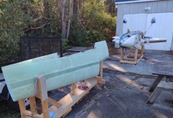
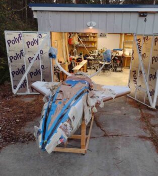
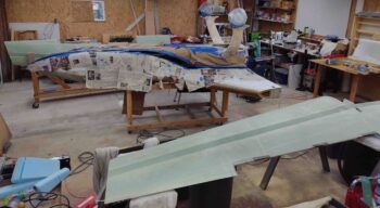
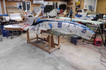
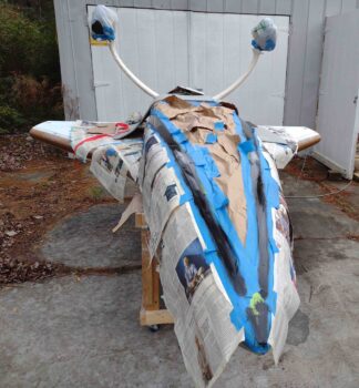
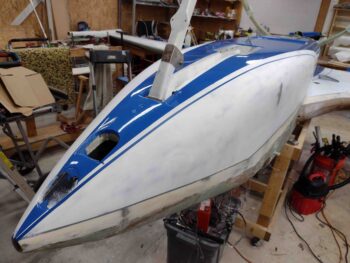
As I was creating the day’s task list this morning, which focused on removing the wings to allow me to take the fuselage outside and sand down the micro on the gear legs, I then started hearing drops of rain on my roof… and once it began it didn’t stop.

Well, flexibility is the key to airpower . . .

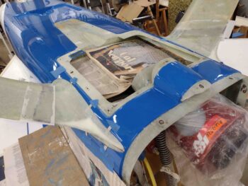
So I pivoted and decided to tackle the issue I identified a couple of days ago when I attempted to reinstall the EZ Nose Lift nose gear actuator.  The arm on the actuator was actually catching the NG3 bracket since it extended out beyond the internal NG4 bracket on all sides.  It may have been easier to deal with this before I reset these brackets in place with industrial adhesive, but I figured the clearance was tight before and I didn’t see anything changing from the previous setup.

Well, I miscalculated that just a bit since the actuator arm would not mount inside of the NG3/4 bracket to then be secured with the AN4 bolt.

My concern about trimming away the excess NG3 bracket was HEAT.  I didn’t want to infuse too much heat into the brackets and thus destroy the industrial adhesive bond that I had just worked in an effort to have a more secure NG3/4 bracket vs using flox in the bond.

Well, with the somewhat thicker stainless steel acting as a heat sink of sorts, and with the great heat resistant properties of stainless steel, heat didn’t really prove to be near the issue that I thought it might.

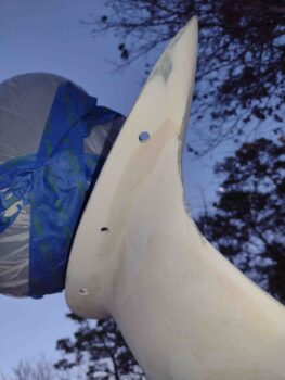
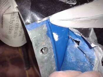
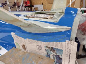
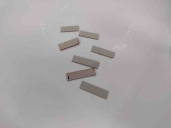
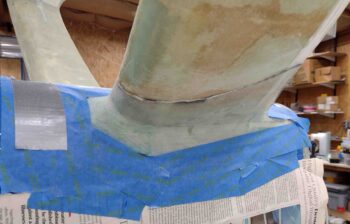
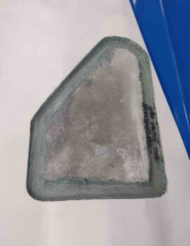
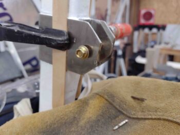
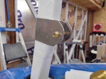
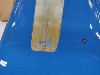
Here we have the first vertical edge of the NG3 trimmed away using the Dremel Tool with a cutoff disk.

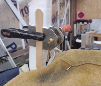
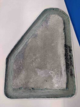
As I was finishing up yesterday’s blog post, I would simply cut an edge (as above) then would wait 20 minutes or so for all heat to dissipate before cutting the next edge, which here is the other vertical aft edge of the NG3 bracket.  As you can see, I was simply trimming the exterior NG3 bracket to match the internal edges of the NG4 bracket.

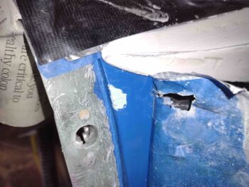
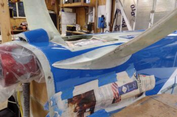
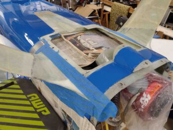
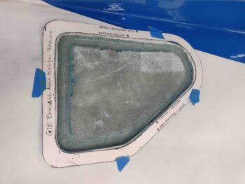
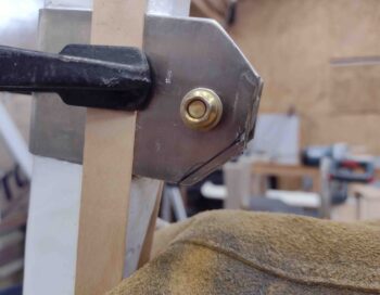
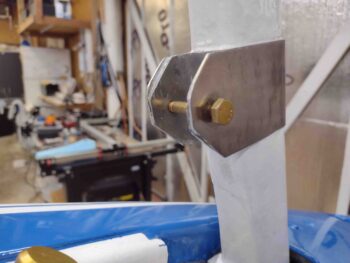
The main “snagging” culprits in denying the proper clearance to the nose lift gear actuator arm were the aft vertical and top (inverted here) angled edges.  So next up was the top angled edge of the NG3 bracket, which I marked here with a Sharpie . . .

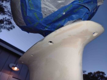
And trimmed away as we see here in this outside shot.

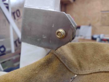
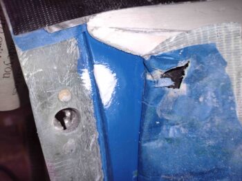
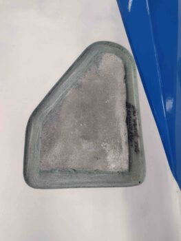
And a shot of the edge alignment between the NG3 and NG4 brackets.

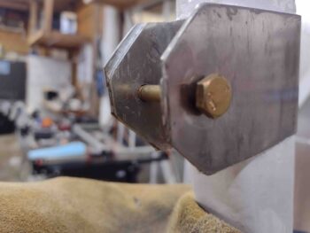
I then repeated trimming the top angled NG3 edge on the other side.  I then took just a hair off the “corner” where the vertical edges met the lower angled edges (top here as inverted).

I then took a file to the trimmed edges of the NG3 bracket to clean it all up.  Trying to get the Dremel Tool in to make these cuts, with the nose gear channel underneath the leather shop apron had my Dremel hand moving at odd angles over an irregular surface… which unfortunately resulted in a couple small kisses on the edge of the NG3 with the Dremel cutoff disk… no structural damage of course, just a couple unsightly nicks.

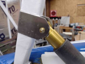
Nonetheless, this task is complete and it allowed for a fairly easy insertion of the EZ Nose Lift gear actuator arm to then be mounted to the NG3/4 brackets.

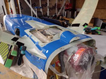
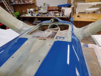
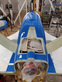
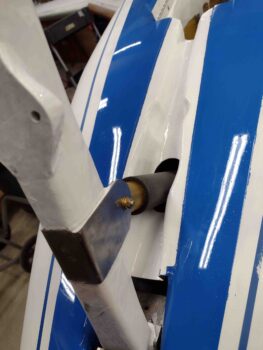
Here’s a closer shot of the remounted EZ Nose Lift gear actuator arm in the NG3/4 brackets.

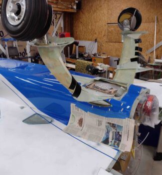
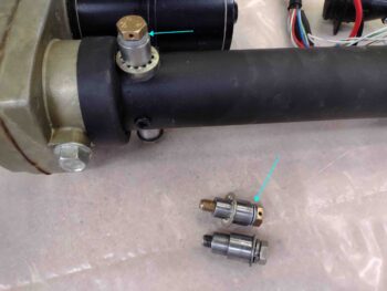
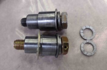
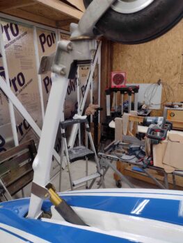
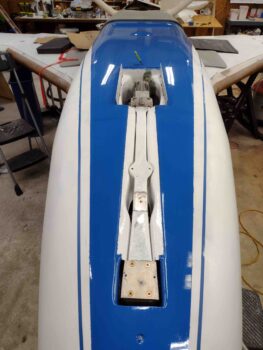
And a shot of the EZ Nose Lift gear actuator arm transiting the white painted nose gear strut channel.  I of course remounted the nose gear actuator with the new pivot bolts and pins into the NG30 nose gear brackets.  This was a tricky feat going in from below and doing it all inverted, and took a good 45 minutes to accomplish.

I then hooked up the nose gear actuator to power and tested it out.  To be clear, this was the first ops check of not only the geometry of the physically remounted nose gear actuator, but also a test of the molex connector that I inserted into the nose gear wiring circuit to allow easy disconnection and removal of the NG30 cover.

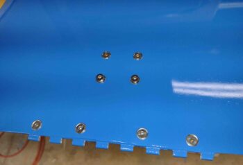
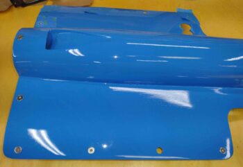
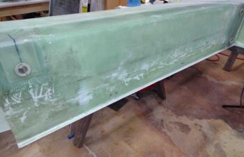
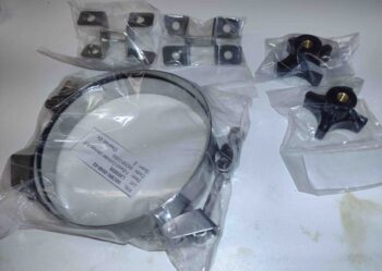
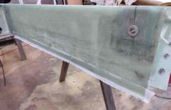
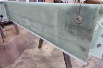
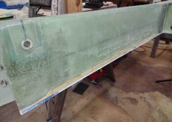
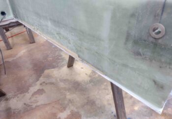
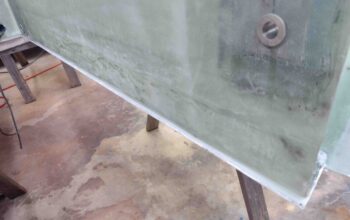
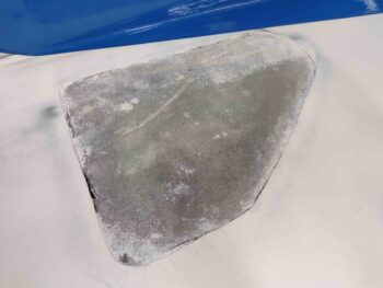
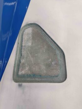
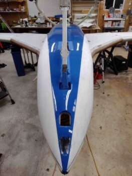
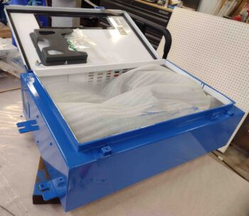
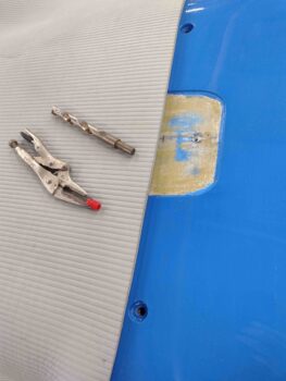
As the rain continued to pour I decided to knock out another pre-flip (back upright) task: the final installation of the GIB thigh support sump tanks fuel drain valves.

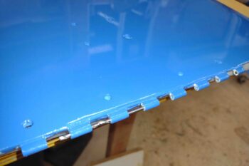
I first removed the red plastic NPT plugs that I had installed to protect the threaded ports during the fuselage painting process.  There was a slight ridge of paint around the edge of the ports so I used a 1/2″ drill bit to remove these respective paint ridges.

I spent a good hour researching the sealant I should use to keep these fuel drain valves from leaking.  I visited our building buddies over in the VANs aircraft forum (VAF) as well as consulting my notes.  Asking what the best fuel sealant is to airplane builders is about like asking people who the best sports team is… the responses are all over the map.

One sealant that kept seeming to get rave reviews is the same sealant Matco calls out for use on all their brake fittings: Loctite 567.  And if you read its label it looks like just about all the other sealants folks are using: Permatex #2 or #3, Tightseal, and Rectorseal, etc. PTFE seeming to be the main underlying ingredient in all of them.

So, with Loctite 567 in hand, I pressed forward.

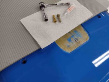
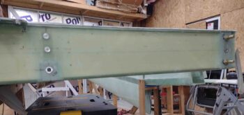
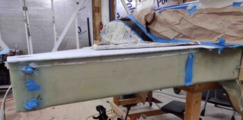
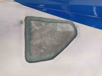
I will say the one area of agreement with most plane builders is to avoid thread tape like the plague, with a few old hands saying that once it’s used it will contaminate the threads and allow introduction of it into the fuel system.  Well, I did use it as a temp seal to check for leaks in my fuel system with water… thus, I very thoroughly cleaned all the threads on the fuel drain valves as well as the female NPT threads of the sump drain ports on the belly of the bird.

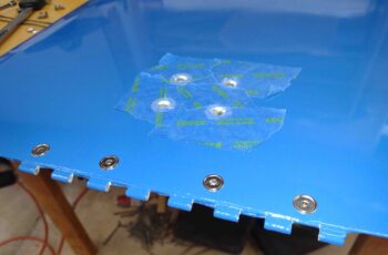
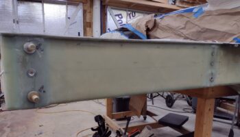
I then applied the Loctite 567 to the threads as per the instructions and installed the sump fuel drain valves into the fuselage…. hopefully for the only and last time!

Tomorrow I plan to get back to my shenanigans of sanding down the micro on the gear legs and back to painting the fuselage and strakes.

Chapter 25 – Gear legs micro’d

Today I started off by pulling the peel ply from the 1-ply BID layups securing the gear fairings to the main gear legs.  I also removed the 1/32″ spacers that provided a gap during the fairing install that will result in the gear fairings “floating” above the surface of the painted fuselage with just enough of a gap to allow for gear movement without damaging the paint or surface of the fuselage… at least that’s the goal.

Mike Beasley employed this method of installing his gear fairing and he’s reported that after a good year+ of flying his Long-EZ that he has no damage or scuffing on the fuselage.

Here’s the other side.

And a couple shots from the front side.

I then spent nearly 45 minutes taping the fuselage all around the gear legs/fairings in prep for both sanding and microing up the legs.

I gave the freshly cured BID that secures the fairings to the gear legs a good sanding, as well as the top of the gear legs (bottom as situated here).

Originally I had planned on only finishing the bottom of the gear legs, so only sanded that area.  I quickly realized how silly of an idea that was so today I sanded down all the surfaces of the main gear.

I then got to work micro’ing up the gear legs.  I used regular micro with about 30% West 410 added to the mix.  This ratio really does seem to work the best in all the iterations that I’ve tried.

Also note the black electrical tape around the perimeter of the gear fairing.  Just as I did on the canopy frame, once I applied all the micro finish to the gear legs, I then pulled the black electrical tape to leave a very clean, micro-free edge around the gear fairings.

Again, just like the recent canopy frame and the aft nose/avionics cover micro finishes, it’s really cool to see the splotchy, multi-colored, irregular surfaces get smoothed out and in one solid color.  Clearly that changes a bit during the cycles of sanding and priming, but it’s a cool process to take these components to paint.

One last shot of the freshly micro’d gear legs.

Tomorrow I plan on removing the wings and taking this bird outside to sand down the micro on the gear legs, and then rolling right into epoxy wipes.

Chapter 13/24 – Gear fairings installed

Today was all about getting the main gear fairings installed.  Following the example of the brilliant and benevolent Mike Beasley, I cut up a bunch of cardboard 1/32″ (0.031″) spacers.

Using painters tape I then secured the spacers a few inches apart underneath the edge of each gear fairing.

After painting on a thin application of epoxy to the mating areas on the gear, I then applied flox to the gear leg and slid each gear fairing down into place, so that it rested on the 1/32″ cardboard spacers.

I then taped and clamped the gear fairings in place to ensure the edge was nice and tight against the gear… to result in the smoothest transition as possible from fairing to gear leg. I then left the flox to cure.

I then started work on reinstalling the nose gear actuator.

After a number of canard aircraft pre-buy inspections, Marc Zeitlin has reported some issues with the Jack Wilhelmson EZLift nose gear actuator securing pivot bolts coming loose.  It’s been an active thread periodically on the Cozy discussion boards.  Various cures to these ails have included Jack’s new pivot pins with star washers (on hand), Nord Lock washers to secure the pivot bolts in place (on hand), and ANH5-12A drilled head bolts to secure with safety wire (on hand).

However, when I was reading the original install instructions, I ran across something interesting where it stated that if you swap out the bolts, ensure they are the same length. If too long they can hit the internal threaded screw and lock up the actuator.  I would surmise that this would result in damage as well…

I do have the same size replacement bolts on hand, just with drilled heads for safety wire. But the Nord Lock washers (light blue arrows) present a potential problem, since they are much thinner than the original split ring and standard washer pair… about 0.1″ difference between the two setups.

Hmmm… what to do?  So I called Jack.  He said that the issue was that there is a slight pivot of about 5º each direction as the nose gear transits up and down.  Moreover, if there is a slight misalignment during install it will cause one or both bolts to slowly loosen up due to this pivoting action.

Thus, the Nord Lock washers —designed to really lock down a bolt against vibration— are not the best suited for this application, and also why there is a split ring washer in the mix. Jack did think safety-wiring was the best option to keep the bolts in place, as even with the slight pivot action occurring there would be just a hair enough give in the wire to allow for the minute movements required.

Between the spacing issue and actually too good of gripping action with the Nord Lock washers, I pulled them from the lineup and went back to using the original flat and split ring washer setup.  I am still using Jack’s upgraded pivot bolt pins with star washers, and the drilled bolt heads for safety wiring (the bolts in the pic below are actually the same length, just angled in different directions).

With my hardware squared away I then prepped everything to reinstall the nose gear actuator back into the nose of the plane.  However, I then encountered a clearance problem with the NG3/4 bracket catching the edge lip on the nose gear actuator arm. Essentially the NG3 that wraps around the nose gear strut protrudes about 3/16″ farther aft than the interior NG4 bracket and is catching the lip on the actuator arm.  It did this very slightly before, but after remounting the NG3/4 brackets with industrial adhesive it is pronounced enough to block the insertion of the actuator arm.

I didn’t grab any pics of this, but will.  I’ll ponder on my corrective actions and will report back in another day or two.

With the flox still curing on the main gear fairings install, I then grabbed the epoxy-wiped aft nose/avionics cover and took it outside for a good sanding.  I spent almost an hour sanding it down in prep for minor surface refills and primer.

After it dried from the wet sanding, I saw a few more spots I need to hit.  But for the most part this thing is ready for next steps.

Nearly 8 hours later I pulled the tape and clamps off the floxed in place main gear fairings.

I cleaned up the excess flox and then sanded down the fairing edges at the seam with the gear leg surface.

I then cut a single ply of BID about 2″ wide and laid it up over the seam on each gear fairing, with a minor bit of flox at the transition between fairing and gear leg.  I then peel plied the layups.

Here’s another shot of the 1 ply layups securing the gear fairings to the main gear legs.

I then left the gear fairing glass to cure and called it a night.


Chapter 25 – Bottom paint progresses

Before I flip the fuselage back upright I plan on having the black accent stripe that borders the bottom fuselage blue paint complete, as well as the white paint on the strake and fuselage/nose sides.

These upcoming colors —white & black— traverse across the GIB strake windows and thus I want the window edges to be in their final state before pressing forward on the application of these paint colors.

Starting off, the GIB windows needed some TLC… here we have the right one.  The left looked pretty much the same.

I started off by cleaning up the edges and removing the foam to get a sanding block down in there to shape the sides.  Again, here’s the right side.

And here’s the left side.

To ensure my GIB strake window cutouts matched the window pieces, I grabbed my template and taped it in place.  Apparently I had some glass creep inward from when I glassed the bottom of the strake and my initial glass skin removal from the window area.

I then outlined the internal edge of the template onto the surface of the strake with a fine mechanical pencil.

I then used my Fein saw to carefully cut just inside the inner edge of the lines, on both strakes, and then finished the edges with sanding blocks.  All told, I spent over 2 hours on these strake windows, but voila… GIB strake windows’ external edges ready for paint.

I then pulled the 1/4″-wide blue fine line tape along the edge of the fuselage/nose bottom blue paint to design and lay out the edge of the black accent stripe that will border the existing blue paint on the bottom of the fuselage/nose and strake. The rate of widening from the nose is 1/2″ approximately every 24″.

As with the blue, the black accent stripe will flow off of the fuselage and onto the strake.

Here’s a side shot of the border for the black accent stripe.  It will be another day or two before I get to painting the black stripe, so I let this design germinate a bit in my mind before pulling the trigger.  I may rework the fuselage-strake corner just a hair . . . Also, to be clear I taped up this accent stripe on both sides of the plane.

I then took a break from the fuselage to use the last little bit of daylight left outside of the shop to spend about an hour sanding down the second coat of blue paint on the canopy frame.  I also sanded down the nose gear fairing since it had gotten a few hairs on its surface and just needed a refresh/do-over.

I then mixed up some blue paint and applied the 3rd coat to the canopy, another coat to the nose gear fairing and a few minor touchup spots on the fuselage: one spot right above the right gear leg that actually extends out from underneath the fairing.  The aft edge of the forward nose gear pocket.  And a spot right near the taxi light that I missed when painting the final coat.  All together these fuselage/nose touchups were less than 2.5 square inches.

I will note that although I clean the surface and use a tack rag before every application of paint, on the canopy frame little 1/4-1/2″ black hairs kept showing up all over the front area.  I would pick the hairs out and then re-tip the paint, but as it got dryer my tipping caused a bit of a rough surface.  The bottom line is that I will have to do yet another coat of blue paint on the canopy frame.

After the blue paint, I then mixed up some white primer and applied it the nose, fuselage sides and strakes.  Again, on both sides.

I then left the paint and primer to cure and called it a night.

Chapter 25 – Sanding is my life!

Since I was up fairly late last night I had planned on cheese grating the micro finish on the aft nose/avionics cover before I headed in for the evening.  But I forgot, then fell out, so I started on it first thing this morning.  I’ve observed in the past that although 3-6 hours is around the optimum time to cheese grate micro finish, it can still be fairly easily cheese grated within the next 24 hours… definitely 12 hours is within the window.

So I spent a good 45 minutes cheese grating the micro on the aft nose/avionics cover.  I couldn’t really get in close on the micro piled up on the inboard elevator fairings, so I grabbed a piece of 36 grit sandpaper and went to work on those.

What I discovered was that the micro had cured and was sanding just fine.  I went ahead then and spent well over 2 more hours sanding down the micro to contour it.  I then cleaned off the micro finish and immediately applied the first epoxy wipe [see way below].

I then got to work wet sanding the white paint on the underside of the wings.  This took about 45 minutes per wing.

I used mainly 500 grit sandpaper, but in some of the stubborn spots I used 400 grit. As you can see in these pics, I also removed all the tape and paper that protected the fuselage and strake whilst painting the blue paint on the underside of fuselage and nose.

By this point in the day it was starting to get dark, but I powered through and took the bottom cowling outside and wet sanded it out there.

There are a few spots I missed that I will have to go back over, but for the most part it’s ready for its final coat of blue paint… which again, it won’t get until after I mount and marry up the upper cowling to this guy.  What it will get though is about the first foot of the black accent strip just to establish where that will be.  I’ll then dial in the exact paint scheme on both the top and bottom cowlings when both are installed.

I then grabbed some shots of the mostly cured bottom fuselage/nose blue paint. At this point I had not yet pulled the blue colored fine line tape at the edge of the blue paint.

I will say that the color and shininess of the paint is stunning, but it truly is one of those paint jobs that looks awesome from greater than 6′ away.  It really needs some TLC in very fine grade sanding, buffing and polishing to get rid of both the dust specs and a few paint runs… and to generally smooth out the surface a good bit more.

That all being said, I’m super happy with the color and I’m definitely learning the paint nuances a bit more.

My swoosh on the lower side of the fuselage is is not exactly how I designed my original paint scheme in that it is rounder and lower than what was in my original depiction, shown here.

The original swoosh above was definitely a longer one that was “flatter” in that it was more horizontal than the one I ended up with.  It also was a bit farther forward on the fuselage side than what I have now.

I did the swoosh slightly different to keep it lower on the fuselage so that the bordering black accent stripe would be out of the sun pert near all the time. Plus, I liked the idea of a narrower spike-style bottom blue stripe… in my mind I lessened the curb appeal just a tad with the curvier, farther aft swoosh when the bird is on the ramp, but will have a better look when flying and viewed from below.  Rationalization and fantasy are key on these things… ha!

The main thing is that it is getting done and I’m quickly progressing towards getting this bird flipped back upright and getting it finished (read: in the air!).

Just as I was going to cheese grate the micro late last night and didn’t get to it, I had also planned on doing 5 full epoxy wipes on the aft nose/avionics cover… but alas, I ended up crashing out again and only got 4 epoxy wipes in the bag.  Oh, well.  All is good.

I do have just a few divots that I don’t think the epoxy wipes filled, which is why I had intended on doing 5 wipes total.  I will probably have to do a few surface fills before I primer it.  I will most likely only do one coat of primer since I may have to sand down and add more filler as I match up and mate this cover to the nose, canopy, canard, etc.

Finally, with the blue paint cured enough that it won’t act like super glue, I was able to finally close the door on the freshly blue painted milling machine CNC control box.  It was quite serendipitous that I had some extra paint and was able to knock this out… but I love this color and it really spiffy’s up the control box!

And with that, I called it a night…

Chapter 25 – Bottom blue paint

Today I started by knocking out a comparatively quick micro finishing application on the aft nose/avionics cover. Before I started I snagged one last shot of the cover in its unfinished state.

I then mixed up a fair bit of straight micro (as compared to adding West 410 filler) and slathered it onto the aft nose/avionics cover.

I then got busy painting the final blue coat on the fuselage, as well as the 2nd coat of blue paint on the canopy frame… both shown here.

Another shot of the canopy frame in its 2nd coat of blue paint.

And a shot of the bottom of the nose and fuselage in its final coat of blue paint.

Some shots of the aft bottom fuselage in its final coat of blue paint.

I didn’t recoat the landing brake depression in the bottom of the fuselage, since it currently has 2 coats of blue paint… which I determined is enough for it.

As before, I painted the final coat of blue on the nose hatch door, nose gear fairing, and nose gear doors.

As I also did on the RAM air scoop/hell hole hatch cover and the landing brake.

Although I mixed up the same amount of blue paint as I did the last round, I had a good bit left over… I guess I must be finally learning to lay down the paint in lighter coats!  So what to do with it?

I didn’t want to waste the extra blue paint, so I quickly sanded and cleaned the milling machine CNC control box before applying the excess paint to it.

After painting the CNC control box door, I wedged a piece of steel bar into the latch and set it in the open position as I painted the rest of the control box.

With even more blue paint left in the cup, I quickly cleaned up the old rusty shop electrical box and applied a good coat of blue paint on it as well.

I then left all the blue painted components to cure overnight.