Chapter 21/22 – RAM air scoop done!

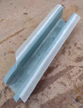
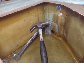
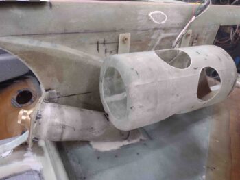
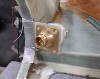
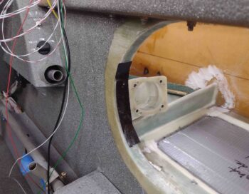
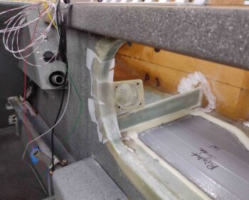
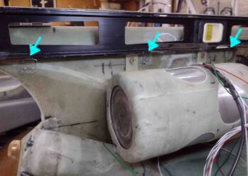
I started out today checking over my just-floxed-in-place duct/vapor box/RAM air scoop. All looked good so I proceeded to add a dollop of micro at the widest point of the RAM air scoop on top and then laid up a 1″ wide ply of BID —essentially a strap— to secure the RAM air scoop to the BL23 rib.  I then peel plied the layup.

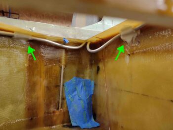
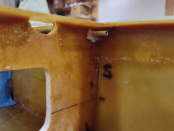
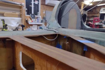
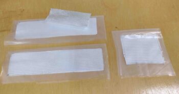
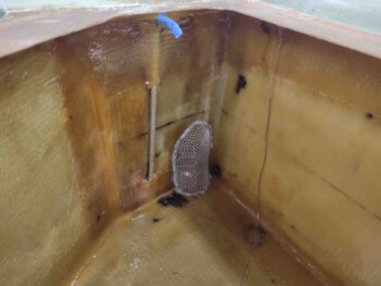
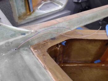
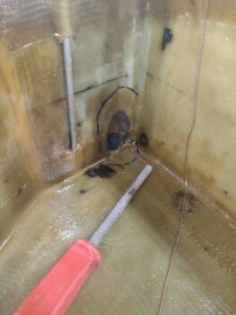
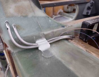
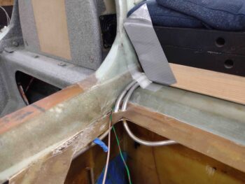
I also checked out my other dollop of micro with a ply of scrap UNI over it to hold the right fuel vent lines in place in the corner of the longeron and CS spar.  I laid this up last night to cure overnight.

Remember, this area will all get covered with the upper cowling sloping shoulders.

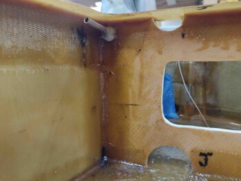
This AM I had a bit of micro left over in the cup from my RAM air scoop securing layup, so I pushed it in and around each of the vent lines going into the turtledeck.

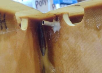
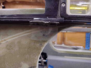
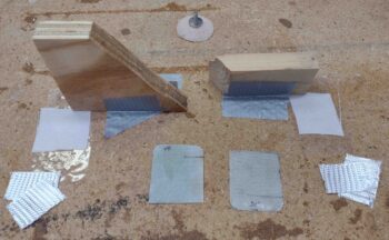
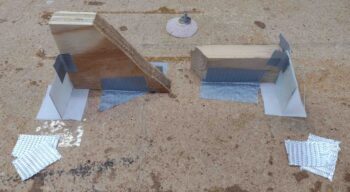
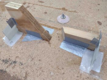
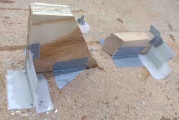
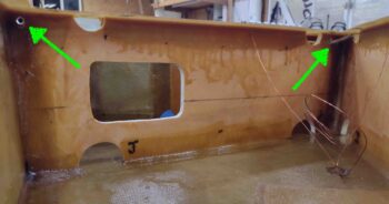
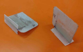
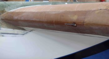
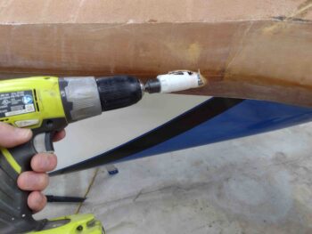
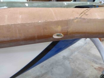
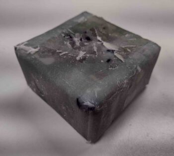
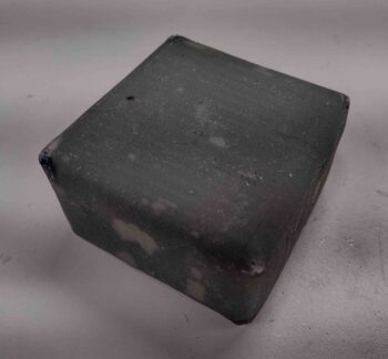
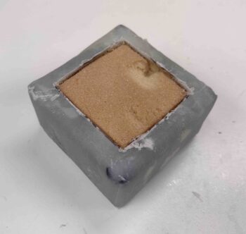
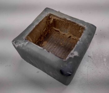
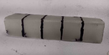
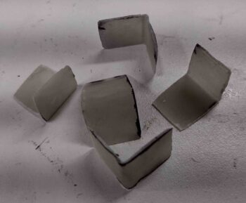
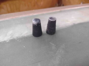
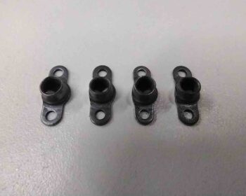
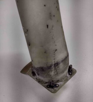
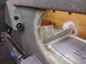
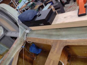
Last night I had just a smidgen of flox left in the cup so I quickly drilled holes into 3 of the 90° 3-ply brackets and floxed them up under the taped level, that was of course sitting on the cross line of where the underside edge of the strake top will sit.

This morning I removed the tape securing the tabs to the underside of the level and then removed the level… Voila! Tabs to hold up the inside edge of the right strake top during install.

I then got busy with what turned out to be quite the layup.  Also a significant feat in that this puts to bed a 6-YEAR project on this oil heat system Scoop & ductwork!

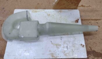
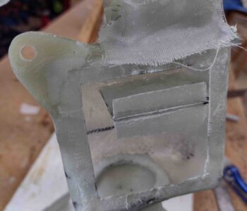
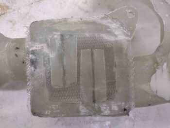
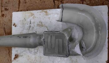
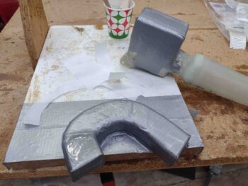
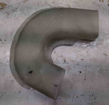
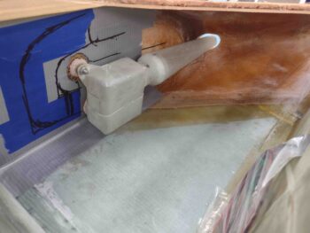
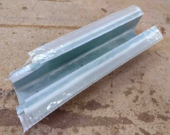
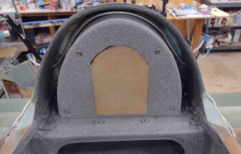
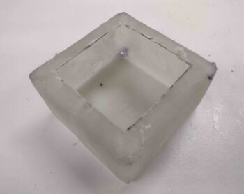
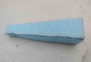
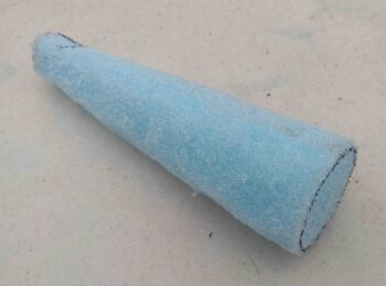
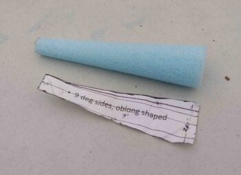
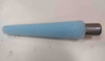
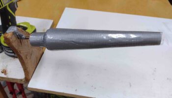
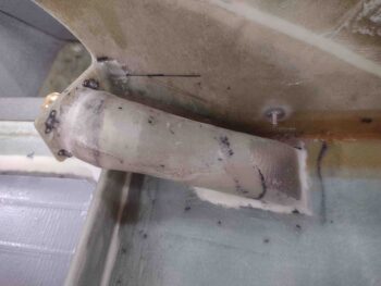
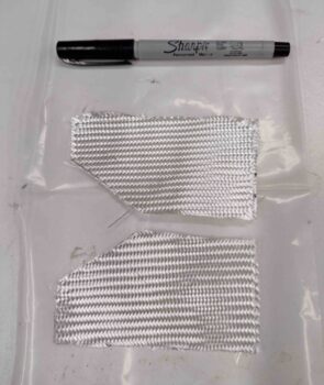
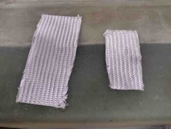
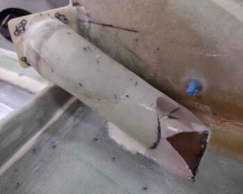
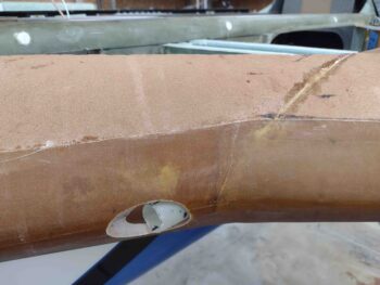
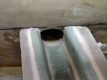
My final piece of the puzzle was to micro, install, glass and peel ply the RAM air scoop cross duct/bridge into place.

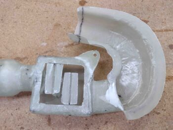
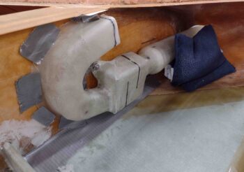
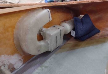
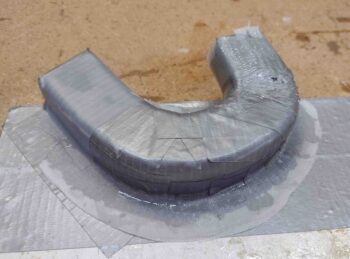
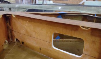
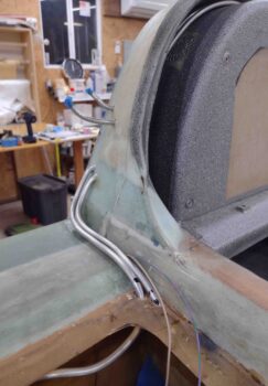
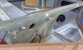
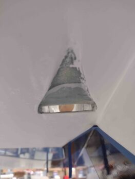
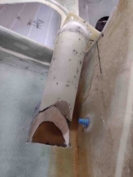
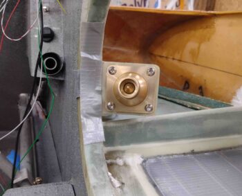
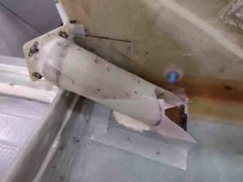
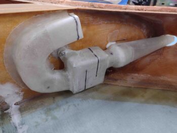
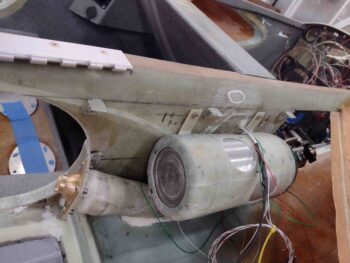
Here’s a shot of the glassed duct/bridge in place.

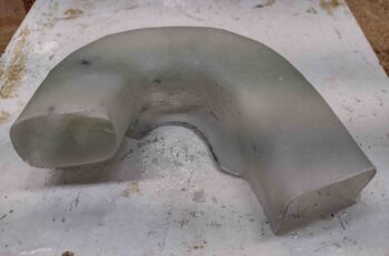
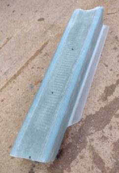
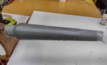
And yet another shot from above.  I’m really happy with how the intersection with the BL23 T-hat and strake leading edge flange came out.

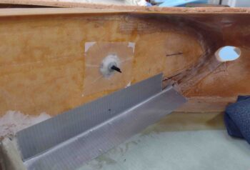
I still need to do some work on trimming the nose of the RAM air scoop and shaping the leading edge around it.

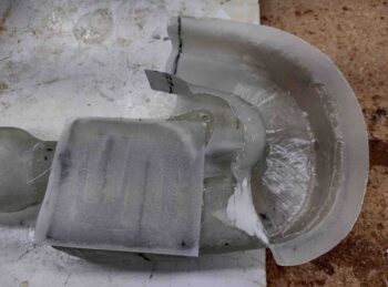
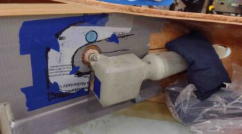
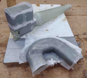
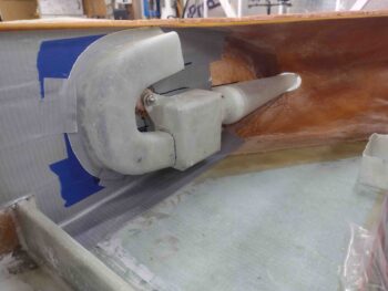
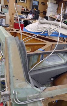
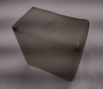
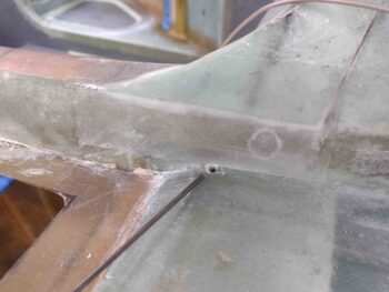
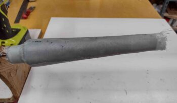
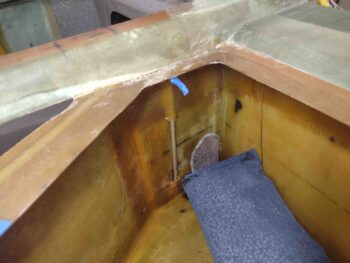
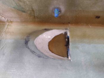
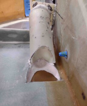
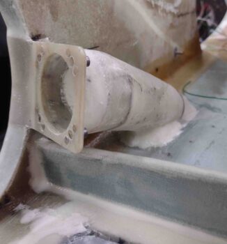
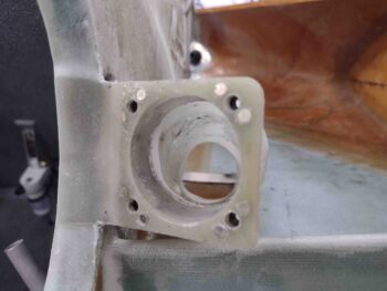
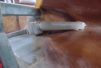
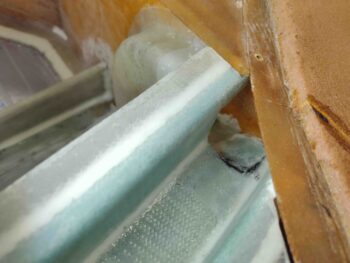
I blended the duct/bridge in with the original oil heat duct entrance through-hole on the side of the fuselage, just aft of the upper pilot’s seat.

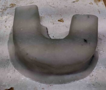
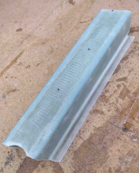
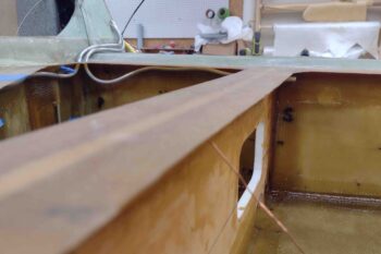
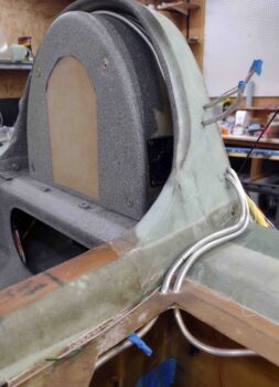
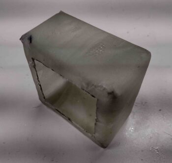
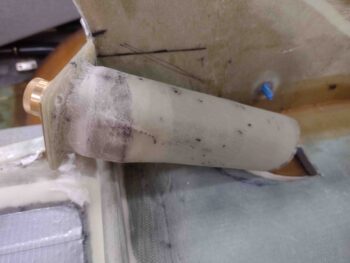
Here’s another shot from the aft side.  Again, I’m extremely pleased with how this came out.

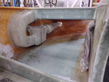
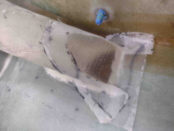
A couple more closer-in shots of the micro and BID transition from the duct/bridge into the fuselage oil heat duct hole.

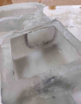
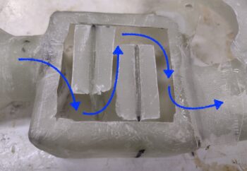
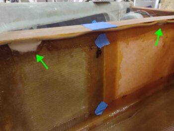
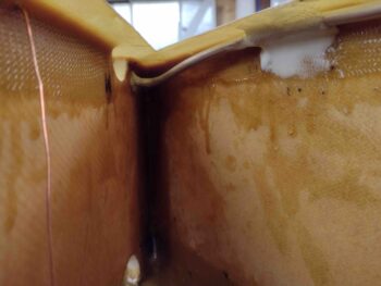
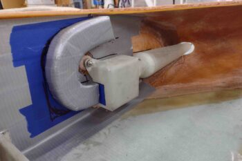
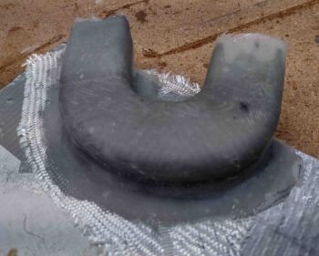
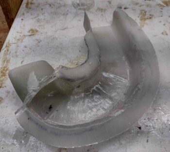
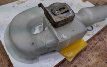
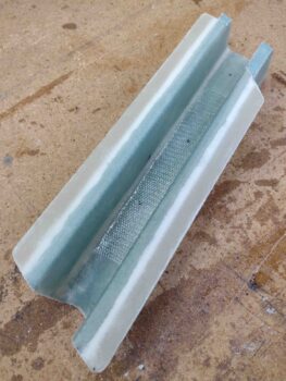
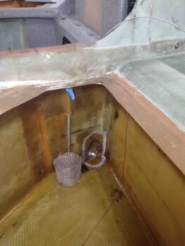
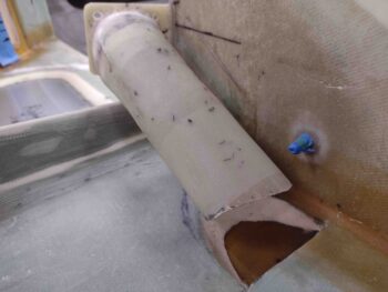
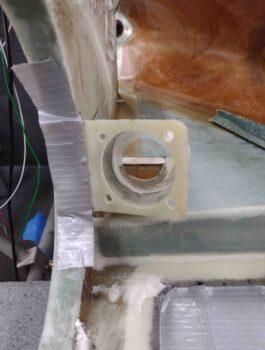
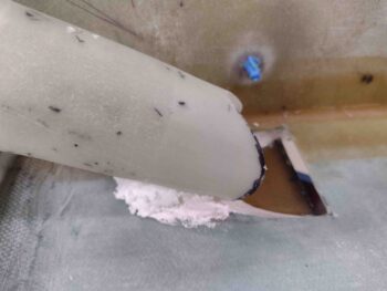
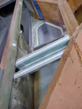
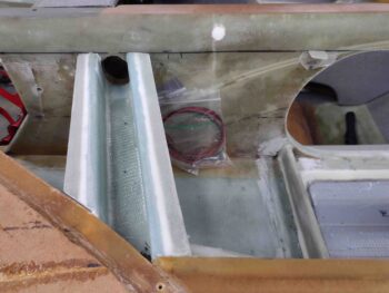
On the the other BL23 side is the where the half-circle duct terminates into the cross duct/bridge.  It won’t win any beauty prizes, but its solid, smooth and seemingly air tight!

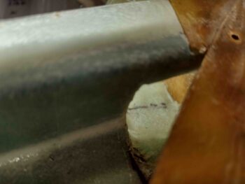
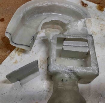
I grabbed this shot to show how the duct/bridge ties into the rest of the left strake structure.

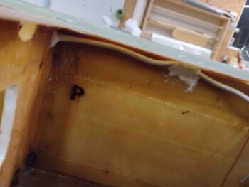
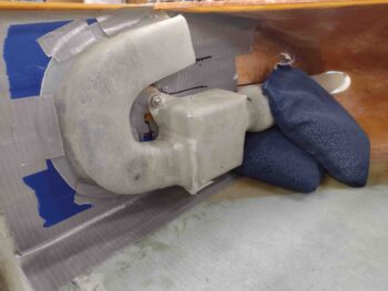
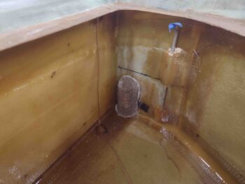
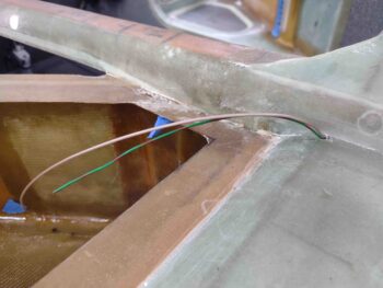
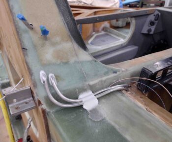
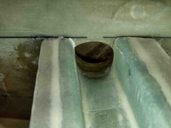
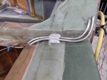
I then weighed down, micro’d, glassed and peel plied the left fuel vent lines in the corner of the longeron & CS spar like I did on the right side.

Here’s a closer shot of that deal . . .

And a few hours later when I took all the weight off and pulled the peel ply.

I’d like to refer to a couple of different lists now (yes, I’m a lists guy!) …

The first list is from a post I made in late June 2017 when I was working on the oil heat air ducts.  It is a list of the remaining phases of the oil heat system.  I went ahead and updated that list here using colors to denote what’s been completed and what I still have to do (i.e. valve manipulation):

  • Phase II – Heat exchanger glassing
  • Phase III – Ductwork interface holes drilled and valves built
  • Phase IV – Ductwork installed with heat exchanger and valves in place
  • Phase V – Oil pump installed & oil lines run
  • Phase VI – Pilot seat area ductwork constructed and installed
  • Phase VII – Instrument panel forward ductwork constructed and installed
  • Phase VIII – Valve cables terminated and handles installed

The next is the strake closeout prerequisites list that I posted within the last couple weeks … let’s check that one as well to see how I’m progressing:

First, the following tasks that were completed:
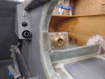
O2 bottle mounting in composite sleeve
Installing main fuel tanks drain screens
⇒ Installing/glassing GIB strake/baggage compartment windows
⇒ Installing/glassing right strake GIB NACA vent duct and eyeball vent
⇒ Installing/glassing GIB strake/baggage compartment cross support mini-bulkheads
Installing/terminating main fuel tanks vent lines
Constructing/glassing/installing left strake RAM air scoop/ducts for oil heat system

That leaves these tasks to be done:
⇒ 
Outboard storage compartments on the top strake side initial tasks
Cleaning up fuel site gages edges (cosmetic)
Prepping/priming/painting strake baggage and final cockpit areas
Wiring and install prep main fuel tanks fuel probes

Wiring fuel site gages LED lights
Installing/glassing/wiring GIB map light
Designing/constructing/installing left/right fuel site gages video camera mounts
Wiring/installing fuel site gages video cameras

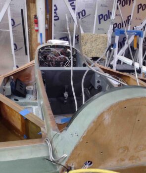
Note how many tasks on the to-do list are wiring.  I’ll further note that I won’t complete these tasks until after the inside of the baggage compartment area is painted… simply because I don’t want a web of wires in my way as I paint.  Nor do I want to paint all my wires that I have nicely color coded and labeled!

Chapter 21/22 – RAM air duct floxed in

I started out today adding micro & flox to the base of the Vapor Box Clickbond before laying up a ply of BID to secure it.  I had originally planned on 2-3 plies of BID, but the air duct will cross over this glass and I didn’t want to add to the gaps or cause any sealing issue.

Furthermore, I peel plied it thinking I would simply add another ply or two as the duct was getting set in place, but that didn’t work out either…. more on that later.

I then pulled the peel ply on the 3 sided (top, bottom, inboard) layup securing the duct to the aft side of the vapor box.  I then cleaned up the layups.

I also Dremeled the corners and sanded the edges of the vapor box aft internal duct opening.

I added a small bead of flox and then laid up the last ply of BID on the outboard side (facing up below) to finish the duct-to-vapor box attachment.

I then got to work installing the vapor box airflow tabs, securing them in place with small beads of flox.

Here we have the aft, lower airflow tab floxed in place inside the vapor box.

I then installed the forward/upper tab using the same method.  I added arrows to the pic below to show how the air will move through the vapor box, with the airflow tabs pulling most of the moisture out of the air.

And finally, a couple more final shots with both airflow tabs floxed in place inside the vapor box.

I then laid up 2 plies of BID on the outboard side of the vapor box to close it up and seal it for air movement.  Here you can see where those “T-hats” on the airflow tabs really helped in supporting the final layup to seal up the vapor box.

I then peel plied the vapor box’s 2-ply BID closeout layup.

While the vapor box cured, I then got to work on securing my not-so-sexy fuel vent tubes inside the respective fuel tanks.  Here we have spots of micro and a ply of BID in 2 separate spots to secure the right tank’s forward fuel vent line.

And the same thing in one spot for the right tank aft fuel vent line.  I also added a dollop of flox on each fuel vent tube poking through the BL23 rib, both on the front vent and aft… also with a dollop of flox on each side of the BL23 rib.

Here we have the left fuel tank with some micro and BID securing the front and aft fuel vent lines.


As I did on the right tank, here’s the forward left tank fuel vent line with some flox keeping it nice and secure.

And a shot of the forward fuel vent line splotch of micro and BID ply, with dollops of flox on each side of the BL23 rib to secure the aft fuel vent line.  Yeah, working from above trying to get your head down into the tank pockets low enough to see what’s going on leads to some more not so awesome looking glasswork… but they work and the fuel vent lines aren’t going anywhere.

A few hours later I pulled the peel ply and razor trimmed around the perimeter of the 2-ply BID layup on the outboard side of the vapor box.

I then whipped up some flox to finally get this whole RAM air scoop, vapor box and duct assembly mounted into the left strake baggage compartment.  I applied a bead of flox to the flanges on the duct and then mounted the vapor box mounting (and alignment I should say) tab to the Clickbond.

As for the Clickbond, I didn’t add any more plies mainly because the face of the Clickbond had too much flox and glass on it and was keeping the duct flanges off the BL23 sidewall just a hair… so I had to do some judicious sanding on both the Clickbond face and the vapor box mounting tab. Which did the trick. But no more plies of glass for this bad boy…

With a bit of flox leftover, I went ahead and mounted one of the 90° angle 3-ply tabs on the side of the fuselage.  I then added a ply of BID over the tab with some peel ply.

About an hour later (I used fast hardener) I pulled off the tape that was securing the duct to the BL23 inboard sidewall.

I then left the floxed duct to cure overnight. I have to say, so far I’m really digging what I’m seeing on this RAM air scoop setup.


Chapter 21/22 – RAM air scoop duct

I spent nearly all day today simply designing, modifying, and creating the oil heat RAM air scoop duct that moves the air from the RAM air scoop/Vapor Box to the upper duct/bridge.

I initially drew up the duct shape on the blue painters tape, then I needed to transfer that to cardboard.  I couldn’t find my tracing paper, so I simply used a plastic bag that a buffing pad came in.

I then transferred the duct shape to some cardboard, made a myriad of tweaks and finally came up with this.  I’ll note my standard duct size in this system is 3/4″ high x 2″ wide for a cross section of 1.5 square inches.  I didn’t have enough space with this tight U-turn to do my standard dimensions, so I went with 1″ high x 1.5″ wide, clearly giving me the same cross section.

The duct mold is simply 1″ thick urethane foam that I cut and then radiused the top/inboard edges.  I then covered it with gray duct tape.

Note the blue rectangle tape on the aft of the vapor box.  That tape is also 1″ x 1.5″ but is set inboard by about 0.040″.  I clearly needed to make a “ramp” from the vapor box to the duct entrance, so I did that below before I started glassing the duct form.

After creating a ramp at the entrance portion of the duct (left below) I collected all my glass, peel ply, etc. and prepped for the layup.

I also added, shaped and taped a small piece of urethane foam to the bottom of the vapor box that will be a slide in/out removable tray that will hold a sponge for water collection… thus eliminating having a hole through my strake skin.

I whipped up some epoxy and started by adding internal peel ply to the duct mold.  I also glassed all the way around the ramp entrance (over peel ply) since it will not be attached to the BL23 rib like the rest of the duct.

Here we are a couple of hours later with the duct glassed as well as the vapor box water collection tray.

A few hours later I pulled the water drip tray off the vapor box completely, and also pulled the peel ply from from the duct form.

Here’s a shot of the other side showing the peel ply pulled from the duct form layup.

I then pulled the duct form out and trimmed up the glass.  Here’s a few shots of that:

And the inside with the duct form and peel ply removed.

I then quickly mounted the RAM air scoop/vapor box to test it with the drip tray in place.

I then removed the drip tray and test fitted the newly glassed duct segment. With the duct piece in place, I marked the outline of the intersecting duct to the vapor box.

I then cut out the marked duct on the aft end of the vapor box, and glassed the duct segment to the vapor box on 3 sides: the top, inboard (facing up) and bottom.  I’ll glass the outboard side tomorrow.

After about an hour cure time, I re-installed the RAM air scoop/vapor box/duct segment to ensure the configuration was correct and locked into place.

It doesn’t seem like it should have taken that long to simply create the duct form and then glass it, but there were a key number of intricate details at play that required a number of re-tweaks… but she’s done now.  Let’s just hope it works as designed!

Chapter 21/22 – Target: Cabin Heat!

This morning I started out by popping free the oil heat RAM air scoop cross duct/bridge from the clear packing tape I laid it all up on.  If you remember, I put peel ply down first before laying up the flanges.  I also peel plied both ends for any added plies of glass that will be required.

I then pulled the peel ply and razor trimmed the glass.  Here’s a shot of the outside, which is actually the bottom of the duct/bridge and the sides of course… a shot each end.

I then took a couple of shots of the inside as well.,, again, from each end.

I then got started on the myriad of nitnoy tasks.  First off, I made up the vapor fins that will get attached inside the vapor box, the forward one hanging down from the top of the box, and the aft one attached to the floor.  This will make the air have to do a couple of slalom weaves to get into the air duct… which should significantly help pull the moisture out of the incoming air.

To assist with laying up the back (outboard) wall of the vapor box, I am glassing mini “T-hats” to the outboard edges of the fins to provide some bridge supports for the backside glass.  That’s what all this commotion is in the pic below.

Also, at the very top you can see a spare, previously-glassed piece of 3/8″ PVC foam that I’m using as a pedestal/spacer for the Vapor-box mounting tab Clickbond (see next pic)

. . . the Clickbond to go through this tab which will be attached to the upper aft corner of the Vapor Box with flox & glass.  Note that the tab itself is G10 phenolic.

I then mixed up some epoxy, laid up the T-hat glass on the Vapor Box fins and also floxed the Clickbond to its foam/fiberglass pedestal.

Here’s a shot from the other side.

And here we have the Vapor Box mounting tab floxed and glassed into place with 2 plies of BID.  I peel plied this layup as I did the T-hats above.

Quite a few hours later I significantly decreased the width/depth of the Clickbond base and then micro’d (since I removed the backside glass) it to the BL23 rib… with just a dab of 5-minute glue in the middle to help secure it quickly.

My last task of the evening was actually a REAL build task, as per plans (and CP). I ran the fuel tanks’ vent line tubing from each tank, through/up/over/down the Turtledeck to then pop out the other side.  This is how Chris Randall did his fuel vents and it seemed the easiest of all solutions, so I followed suit.

Here we have the right fuel tank vent lines in place.

And here’s the forward vent line in the left fuel tank in the top pic, and the aft vent in the bottom pic. I’ll note that with all the extra bending and machinations that I went through to get these vent tubes in place, they are not the straightest or prettiest vent lines you’ll see… but they work.  And once the tops are on these strakes hopefully none of us will ever see these ugly things again… ha!

The fuel vent lines coming out from around the GIB headrest reminded me of some sea creature on the ocean floor, tentacles at the ready in search of food… but I digress!

Here’s a shot of the vent lines going through the flange I created to flox the upper strake skin to… note that since I have Mike Melvill’s cowlings that there are shoulder bumps that come forward of the cowling in the corners between the strake and Turtledeck.  Thus, to keep the vent lines out of the cockpit, and put the transition holes out of the tank on the top vs the side of the tank, I ran the fuel vent tubes along the aft longeron to then upwards into the Turtledeck.

Another shot of the fuel vent line tubing, both on the side of the longeron and entering the Turtledeck.  Ok, and the weird stuff coming out of the middle!

It took a fair bit of finagling to get the lines around the top of the GIB headrest and out the other side, but I eventually got them all.  Thank God I gave myself extra length on these tubes, because I tore the ends to hell getting them out of the interior Turtledeck.

After I layup all the extra glass on the Turtledeck for the top cowling mounting flanges and then micro finish it in prep for paint I’ll trim the fuel vent lines flush with the surface of the Turtledeck.  Again, this is how Chris Randall did his and he has a ton of years of trouble free flying with his fuel vent tubes configured this way.

I’m not overly pleased with how these vent lines look inside the Turtedeck and I am honestly pondering how best to hide them.  Regardless, there they are in their current state.

BTW, here’s how those Vapor Box fin T-hats turned out… not bad for a ply of BID each side.

After I did my minor/myriad tasks above, I took a bit of time to make up prepregged 2-ply BID tapes for the duct/bridge when it comes time to glass that in place.  I also prepregged 2 plies of BID for the aft/outboard wall of the Vapor Box to close that out.

And with that… I definitely called it a night!


Chapter 21/24 – More oil RAM air

I started off today by reclaiming a piece of 3/8″ thick PVC foam for use to create the top air duct in the left baggage compartment that crosses over from the BL 23 rib to the oil heat duct entry hole in the side of the fuselage.

First off, the foam is reclaimed from what??  Well… from the squirrels that like to call my workshop home.  On the back side is a big swath of squirrel poop, so I cut around it to use what I could before throwing the unusable section away.

I created the upright sides of the Oil heat RAM air scoop cross duct from the piece above and then used another piece for what will be the bottom section, which is at the top here as I used micro to glue all the pieces together.

Now, in my quest to multi-task, dual purpose components when able and generally and proverbial kill two birds with one stone, this is not just a duct, but a reinforced bridge, or bulkhead really, to help support the top left strake skin at the common GIB entry point on these birds.  It’s essentially a lightweight but sturdy “U” channel that will help support the load of any GIB/pax who needs to enter the aircraft via the strake.

And here it is in place.  Note that although not perfectly matched to the current oil heat duct entry hole in the fuselage sidewall, it will do the job —once glassed— of getting the pressured air from the RAM air scoop intake into the oil heat ductwork.

Here’s yet another shot from the aft end of the left baggage compartment.

I then glassed the interior surface of my new dual purpose oil heat RAM air scoop duct (and bridge!) component with 1 ply of BID.  After I got all the internal area BID wetted out and laid up, I then flipped the duct/bridge upside down to create flanges on each side somewhat like the T-hats on the strake ribs to allow for top strake skin attachment to this part.

In fact, I put peel ply underneath the flange BID so that when all is said and done, I can just rip the peel ply off and have the flanges ready for the top stake skin attaching.  I also added peel ply on the top (as situated here) of the flanges to allow for another ply of BID to be laid up glass-to-glass when I layup the external ply of BID (see below).

While the duct/bridge internal BID layup cured, I then got busy further determining the configuration of the RAM air scoop in its mounting through the strake leading edge.  Once I felt comfortable with how it would be mounted, I then traced the aft RAM air scoop duct onto the front face of the vapor box.

After cutting the hole in the vapor box and test fitting the RAM air scoop duct, I then ran a bead of medium dry flox around the outside interface/junction between the vapor box and the RAM air scoop duct.  I then glassed the junction with a ply of BID and peel plied most of it.

Internally I ran a bead of micro around the protruding lip of the RAM air scoop duct.

Here you can see the 1-ply BID layup securing the RAM air scoop duct to the front face of the vapor box.

After joining the RAM air scoop to the vapor box, I then razor trimmed the internal 1-ply BID layup on the RAM air scoop duct/bridge piece.

Here’s the other end of the RAM air scoop duct/bridge piece razor trimmed.

After the RAM air scoop/vapor box combo cured a bit, I then set it in place inside the left strake/baggage compartment to ensure the final configuration was good while I could still position the two components in relation to each other if need be.

Here’s a side shot of above.

By this point the internal 1-ply BID layup on the duct/bridge had nearly fully cured, so I pulled the peel ply and prepped the external foam for a 1-ply BID layup. I sanded both bottom corners to give them a good radius, then whipped up some epoxy and micro to prep the foam surface.

I then laid up the ply of BID on the external surface of the duct/bridge.

I then peel plied nearly the entire BID layup and then left it to cure overnight.

Tomorrow I’ll press forward with the oil heat RAM air scoop & ductwork as well as other strake closeout prerequisite tasks.

Chapter 21/24 – RAM scoop vapor box

This morning I started out by trimming the glass on the front entrance and aft exit of the oil heat RAM air scoop, then pulling the peel ply from the outside surface, and finally removing the bulk of the blue foam to allow me to pull the tape and peel ply from the inside of the scoop.  All in all everything looked fine with the scoop.

I’ll note that by the nature of using blue foam covered in tape to create an object, the surface inside the object is not going to be perfectly smooth… unless of course you can get at it to sand it down.  I’m not going to be that committed on this RAM air scoop unless it simply proves to cause the air to be too turbulent to function.

I then pulled the trigger and drilled my pilot hole into the leading edge of the left strake, slightly below centerline, which is where I’ll mount this oil heat RAM air scoop.

I then cut the actual hole with a 1″ diameter hole saw.

With the resulting hole looking like this.  I did increase the size of this hole a good bit… I’ll have to get a pic of it later when I finish the RAM air scoop install.

To pull out any moisture or water vapor coming through the RAM air scoop, I’ll send the air through a “mouse maze” in a chamber (enclosed box) containing upward and downward situated tabs.  This will help pull out any water and dispense/collect it on the floor of the chamber, where there will be a small drain hole out the bottom of the strake.

I determined this chamber, or “vapor box” that I refer to it as, needed to be 3″ wide x 3″ high x 1.6″ deep.  As luck would have it I found the old urethane foam mold core that I used to create the GIB right armrest storage pocket, that is 1.6″ thick.

I then simply marked a 3″ x 3″ square, cut it out… and voila!  The foam mold core to my RAM air scoop vapor box.

I then taped it up and cut 2 square plies of BID measuring 7′ x 7″ to cover this taped up foam block to create my vapor box.

I peel plied the inside, then laid up the 2 plies of BID.  Then peel plied the outside.  To keep the layup from getting epoxy all over my white work surface, I put a piece of plastic on the work surface.  Well, the BID kept wanting to separate from the taped foam form, so I simple cut the plastic as if I were wrapping up a gift box and taped the hell out of it to keep everything in place.  I then left it to cure.

This is the aftermath a few hours later.

I pulled the plastic and tape off to reveal this… which is the side where all the ends of the BID terminated.  This side will eventually get closed in with another 2 plies of BID and get attached to the left BL23 rib (outside wall of the baggage compartment).

I then pulled off all the peel ply.  This is the other side that will face inboard.

I wanted about a 1/2″ flange on the open ‘working’ side that will give me a lip to layup the final 2 plies of BID that will seal up this box when all the internal stuff is created inside.

I then cut the internal square with the Fein saw and cut the foam deep.

I then popped out the center block of foam and started removing the rest of the foam bits.

I then pulled out the tape and finally the inside peel ply to reveal the beginning shell of my RAM air scoop vapor box.

Here’s another couple of shots of the RAM air scoop vapor box shell.

And with that, I called it a night.

Chapter 21/24 – Oil heat RAM air scoop

This morning starting off I spent a good half hour updating all my task & sequence lists… some of my individual chapter to-do lists and my overall project plan (what I call my Order of Battle <grin>).

Out in the shop I pulled the weights off the main fuel tank drains’ stainless steel mesh strainers that I floxed in place last night.  Everything looked good with these so I taped them up with blue painters tape to keep the dust out.

When I did my final layup on the GIB air vent duct last night I had also set up a prepregged layup of 3-plies BID with peel ply on each side.  I then placed it on the taped edge of a piece of 3/4″ plywood stood up on that edge.  I then sandwiched that between 2 weights and put a shot bag weight on top of the piece of plywood to weigh/squish it all down.  I went to take a pic but all you could see was a pile of weights.  Here’s the result.

This piece of peel plied 3-ply BID 90° angle is around 3/4″ on each leg, and a hair over 4″ long.

Today I pulled the peel ply and trimmed the edges with the Fein saw.

And then made hash lines about every 3/4″.

I then cut the 3-ply BID 90° angle on the hash marks and cleaned up the edges with my sanding block.

I’ll flox 2-3 of these on each side to support the inside long edge of the upper strake skin when I close out the top strakes.  I temporarly taped a couple of them up here on the sidewall to show what I mean:

I then knocked out what should have been a fairly quick task, but the left side gave me some unexplained fits that seemingly defied physics (sigh) . . . I drilled a ~5/32″ hole on each side of the upper CS spar where it meets the upper longeron.

I then threaded the Nick Ugolini fuel probes’ ground wire + signal wire for each respective side up through each hole.  Again, the right side took literally 10 seconds, whereas the left took an inexplicable 10 minutes —replete with the usual wailing and gnashing of teeth— since the second wire was hanging up somewhere internally in the hole.  But I prevailed!

The next task at hand was one I wasn’t particularly looking forward to… creating a blue foam mold for the left strake leading edge located RAM air scoop for the oil heat system. This RAM air scoop will feed the engine-oil fed heat exchanger with pressurized air via the ductwork to provide the Holy Grail of convenience in these birds (if it works!): HEAT.

The key to this entire oil heat system is marrying pressurized air with a good heat source. If my oil heat system plumbing proves good, then the other half required in this dynamic duo is this RAM air scoop.  The concept is to take fast moving air, slow it down while minimizing turbulent air, to then provide pressurized air into the air ductwork to transfer the heat from the heat exchanger to the various pilot & GIB feet & face air vents.

The specific key to the RAM air scoop configuration is keeping the internal angle at no more than 11° between the sides.  Admittedly, I’m very close to that max angle since I want to be aggressive with a smaller air scoop in transferring air velocity into air pressure.

Clearly what we have here is the machinations I went through to take a chunk of blue foam and slowly transform it into a stretched conical air inlet tube, or a foam mold/plug for one I should say.

I’m not an expert in airflow, but I know one should have a back “wall” of the tube to create a plenum effect before sending the pressurized air on its way.  I made my exit nozzle on the RAM air scoop just a bit smaller than the cross-section of the rest of my air ducts.  I might have should have made the exit duct even a bit smaller, but I plan on making this RAM air scoop somewhat removable to allow for experimentation of various design configurations.

So this is essentially what I came up with… a blue carrot!

I then taped up the blue carrot and set ‘er on a long 1/4″ drill bit as a sort of glassing spit.

After laying in some peel ply at each end, I then laid up 2 significantly overlapping plies of UNI covered by 1 ply of BID.

I then peel plied the layup.  Since I used MGS 335 epoxy with a mixture of fast & slow hardener, I don’t expect this layup to be cured until tomorrow morning.  Thus, I did one final check and left it to cure overnight.

Tomorrow I plan to start on the other components of the oil heat RAM air scoop intake system as well.

Chapter 21/24 – GIB air vent complete

Today was the annual seafood festival here in Morehead City, NC so I was out and about quite a bit before getting into the shop for a few hours.

I made a template and then cut the 2 plies of BID before prepregging them.  I then wet out and laid up the BID plies as the final layup to finish the installation of the GIB air vent duct.

On the duct itself I laid up the 2 plies of BID overlapping onto the edges around the opening.  However, on the forward edge of the NACA duct opening I split the layup… one ply on the inside (top) while the other side overlapped onto the face of the external NACA scoop (underneath).

In between these 2 plies of glass right where they spit into single plies —internal and external— I laid in a bead of micro.

Here we have the external ply laid up on the external face of the NACA scoop.  I then peel plied all the areas that required it.

As I finished up the GIB air vent layups above, I had a decent bit of epoxy left over in my cup.  I decided to use this extra epoxy to flox in the fuel tank drain screens.

I started by tracing the left fuel drain screen with a Sharpie . . .

I then sanded the shiny epoxy under the marked line, and then cleaned the sanded areas with acetone.

I then used the leftover epoxy to whip up some flox to set the left fuel tank drain screen in place. I then used a taped up block of wood with a shot bag weight to secure the screen in place against the tank side wall and floor.

I had just enough flox to do the left side, so I mixed up a bit more epoxy to make up a bit more flox to flox the right fuel tank drain screen in place as well.  I then weighed the screen down a little to press the edges firmly against the tank side wall and floor.

And just so YOU know…. and moreover for MY peace of mind, I grabbed a shot of the two removed protective rubber stoppers that I had in the tanks’ drain tubes to keep dust and debris out.

A few hours later, after the epoxy cured, I pulled the peel ply from the layups.

I then installed the eyeball vent with a new set of screws, and with this I’m declaring the GIB air vent install complete.

I then installed the O2 bottle mounting sleeve to check the clearance with the GIB air vent duct… which is very little. There is just a hair of space between the two components, but I have a fair amount of meat on the corner of the O2 bottle mounting sleeve to remove a bit to create a decent gap (note the black Sharpie marks which is where I’ll do some trimming).

With a week under my belt since I’ve been back from Rough River, let’s revisit the list of prerequisite tasks that need to be completed before closing out the strakes:

First, the following were completed this past week:
O2 bottle mounting in composite sleeve
Installing main fuel tanks drain screens
⇒ Installing/glassing GIB strake/baggage compartment windows
⇒ Installing/glassing right strake GIB NACA vent duct and eyeball vent
⇒ Installing/glassing GIB strake/baggage compartment cross support mini-bulkheads

That leaves these tasks to be done:
⇒ 
Outboard storage compartments on the top strake side initial tasks
Wiring and install prep main fuel tanks fuel probes

Installing/terminating main fuel tanks vent lines
Cleaning up fuel site gages edges (cosmetic)
Wiring fuel site gages LED lights
Installing/glassing/wiring GIB map light
Designing/constructing/installing left/right fuel site gages video camera mounts
Wiring/installing fuel site gages video cameras
Constructing/glassing/installing left strake RAM air scoop/ducts for oil heat system
Prepping/priming/painting strake baggage and final cockpit areas

Chapter 21/24 – GIB vent near final

My very first task in the shop this morning was sanding the inside of the NACA scoop to smooth out the micro and transition between it and the underlying glass.  The dark speckles are due to me cleaning it with acetone beforehand and it pulling in some of the black Sharpie ink into the pours of the micro.  Oh well…

I then applied and left the thin application of epoxy to cure.

I spent about 20 minutes cleaning up the layup that secures the second duct segment to the first.  Since there is an internal edge from the initial duct form fitted into the second/longer duct, I applied some micro inside the duct and covered it with peel ply.

I then test fitted the GIB air vent mount and duct in relationship to the NACA scoop opening.

Here’s another shot of the test fitting.  I then slowly started cutting away the NACA end of the duct.

I wanted to see how the entire assembly would look in general with the gold eyeball vent installed, so I temporarily set it in place.

With the eyeball vent removed, you can see a fairly straight shot —even with the slight duct dogleg— between the eyeball vent and the opening of the NACA scoop.

After a good 45 minutes or so, I had finally trimmed the GIB air vent duct to the shape I wanted, that gave me the best interface with the NACA scoop opening.

I should note that I was a hair off on my floxing and glassing the forward duct segment to the aft one… the resulting gap between the mounting flange and the curved sidewall opening when the forward duct was aligned with the NACA opening was a bit more than I wanted. Although I hate doing this, I took the heat gun to the flange and warmed it up enough where I could manipulate it to then narrow that gap.  My heat trick didn’t eliminate the gap completely, but it did reduce it significantly to a point where I was comfortable with it.  Moreover, my issue with the gap wasn’t really appearance, but rather weight and strength… I didn’t want a larger glob of flox having to take up the space in the gap and do most of the work of holding the mount to the sidewall.

With the initial fitting out of the way, it was now time to mount the nutplates to allow for securing the GIB eyeball vent assembly to the mount/duct.  I used the smaller footprint nutplates but even then the space was so tight I ended up grinding off the small flange on the side of each nutplate.  If you look closely below, the left sides of the nutplates are shaved off.

I then mounted the nutplates to the flange on the GIB eyeball vent mount… which was a very tight fit. (Note the micro under peel ply in the opening of the duct).

My riveting of the nutplates to the eyeball vent mount flange was NOT pretty or done with style, since getting the rivet squeezer into place was challenging lacking the space.  But the nutplates work, are functional, and I’m pressing forward!

Again, I wanted to see how the eyeball vent would work and ensure the screws all fit well so I mounted the eyeball vent to the mounting flange with button head screws.  I’m very happy with the outcome so far.

With nutplates on the mounting flange and my configuration looking good, it was go time. I floxed the mounting flange (aft) to the curved sidewall opening, using just a small blob of 5-min glue in the center for a really fast attachment.

Concurrently, on the forward (NACA scoop) end I piled up some dry micro in a U-shape leaving just about a 1/4″ square area open right where the duct actually contacts the strake/baggage compartment floor.  I also placed a small dab of 5-min glue on the bottom edge of the duct to secure it to this aft edge of the NACA scoop opening.

[I had thought about using pour foam in lieu of the dry micro, but I saw that building dams and shaping the foam would be a lot more challenging —especially on the fuselage wall side where it’s tight— than just using dry micro here.]

After holding the GIB air vent mount & duct assembly in place and tight against its contact points for a few minutes, I then cleaned up the area around the mounting flange.   As you can see in the pic I also used a strip of black Gorilla duct tape to secure the aft mounting flange in place against the curved inside fuselage sidewall.

For securing the forward intersection between the duct and the strake/baggage compartment floor, I had measured (and test-fitted) a template to create 2-ply BID tapes for the job.  I then prepregged the 2-ply BID pieces and wetted them out.  The Sharpie pen is just there to show the size of the BID plies.

I then applied the BID tapes to the junction between the duct and the strake floor. This of course cleaned up the initial jagged shape of the dry micro and smooth it out.  I added a ply of BID on the very aft side to cover a narrow strip of dry micro that was peaking out, and then I peel plied the majority of the exposed edges of these BID plies… to eliminate the possibility of hands/arms/fingers getting shredded when putting stuff in/out of the baggage compartment.

On the mounting flange attaching the assembly to the sidewall, I grabbed 2 pieces of BID out of my scrap pile to use… the larger BID piece on the left covered the flange on the outside corner and overlapped onto the inside fuselage sidewall.

The smaller piece of BID on the right went into the inside corner on the outside wall of the fuselage and can be seen in the pic above with a small piece of peel ply on it.

I then peel plied the outside corner BID layup and left it to cure.

A few hours later I pulled the peel ply from the outside corner BID layup that secures the GIB eyeball vent mounting flange to the fuselage sidewall.  I then razor trimmed the overhanging glass and sanded the remaining peel ply goobers to clean it up.

I also pulled the peel ply on the duct-to-strake baggage compartment floor/NACA scoop layups and cleaned it all up as well.

I realized I hadn’t gotten a good pic of the dry micro filler so I added this shot here.

Finally, I pulled the peel ply and sanded the inside seam of the duct segments to smooth out the internal contour of the GIB air vent duct.

I have to add/shape some micro inside the added BID plies on each side of the NACA scoop. I then have one more 2-ply BID layup to close out the NACA intake scoop and this GIB vent addition will be complete.  I plan on knocking that out first thing tomorrow.