Chapter 23 – Delays & sanding

Today was all about sanding… and more sanding.

And dealing with a technical issue with GoDaddy that apparently was so egregious that they suspended this website… I had 3 backup database files from early 2016 on the root directory of the server.  After multiple phone calls and hours of brushing off an old FTP client to fix the world-ending issue to extricate myself from the geek doghouse, I was once again deemed worthy in their eyes to be allowed to have my website back on the ether!

Remember my rant a few weeks back about geeks and techies?!  Well . . . .

Just prior to me finding out about my near-unpardonable techno-sin, I had finally finished sanding the inside surfaces of each half of the split air induction tubes… around 45 minutes per side.  Overall the inside surfaces were pretty decent, but I wanted smoother: my goal was to take them from a guesstimated 50-60% smoothness factor to 85+% smoothness factor… general made up officious-sounding terms here.

Once sanded, I slathered the holes, divots and imperfections with a concoction of micro + West 410 and set them aside to cure.

I had planned on sanding them an hour or so earlier but then came all the drama with the website hosting.

Returning back to the shop, I spent around 45 minutes a piece (again) sanding the internal surfaces of each air induction tube half.

This round of sanding got the inside surfaces of these suckers pretty darn smooth.

But to take it to the next level and to really seal in the slightly porous surface of the sanded micro, just as with micro finishing the airplane surfaces for paint, I spent my evening hours applying 3 rounds of epoxy wipes to the internal surface of the split air induction tube halves… only here I’m using MGS vs West epoxy for the wipes.

Here we have the first of three rounds of epoxy wipes on the inside surfaces of the air induction tubes.

And with that dear readers, I called it a night.  Hopefully tomorrow I can finally get these bad boys recombined into one tube, eh?!

Chapter 23 – All about the air!

Today was all about working the Fuel Injection Servo air induction tube initial carbon fiber layup.  As an aside, yesterday I discussed my plan and showed pics of my configuration to Alan Jesmer from Precision Airmotive, to which he noted that he didn’t see any issues with what I had in mind for implementing my air induction system.

I started off by using my Fein saw to trim each end of the air induction tube.  I then sanded the edges of each end.

I then spent a good bit of time thoroughly sanding the exterior surface of the air induction tube initial carbon fiber layup.

I say “initial” carbon fiber layup since I need to split the current tube into 2 halves to first extract the 3D printed plug and internal peel ply, and then sand and prep the internal surface to ensure the air gets as smooth of a ride as possible on its way to the FI servo.

Then I’ll layup at least 2 plies of carbon fiber along the seams when I create a single tube again… one ply which will encompass the entire exterior surface of the air induction tube.  Obviously these last layups will be the “final” carbon fiber layups.

Here I marked a cut line on both sides of the air induction tube.  The reason I’m cutting horizontally along the sides vs vertically down the middle (which I would prefer) is simply to keep the buildup of composite material at a minimum along the bottom center of the tube, which is of course the area that is closest to the inside of the bottom cowling… with the least amount of clearance with said cowling.

I again used the Fein saw to cut down the marked cut lines to split the carbon fiber tube.

Of course I still had a pretty much intact 3D printed tube mockup/plug on the inside that I had to pry apart.  After a good 10 minutes and some judicious destruction, with prejudice (ha!), the 2 tube halves finally came apart.

I then spent well over an hour prying out both the plastic and peel ply from the inside surface of the outer portion of the tube.  You can obviously see the 3D print innards on the other half of the tube….

Which I then tackled next.  It was a little easier than the first half of the tube since it’s essentially an outside curve and I had much more access to get in and remove the plastic and peel ply.  Plus, since it’s the inside of the curve, there is simply a lot less surface area.  That all being said, it still took nearly an hour to extract all the plastic and peel ply from this side of the tube as well.

I had planned on doing a bit more, but I had promised Jess that I would spend an early evening and dinner in New Bern with her, since it was such an uncharacteristically warm day (Yes, SHE is clearly to blame! ha).

Tomorrow I’ll give the inside tube surfaces a good sanding and then fill the holes/depressions with a micro/West 410 mix.  After that cures and I sand the micro fill, I then plan on doing at least a couple epoxy wipes to help fill in any leftover holes, gaps and low spots.  Plus I would simply like to have the inside of this tube as smooth as possible.  After the inside tube surface prep is complete, I’ll then rejoin the tube halves and finish constructing the air induction tube.

Chapter 23 – Just Carbon Fiber it!

I started out today by cleaning up and mounting the 3D printed Fuel Injection Servo air induction tube to allow laying up the initial plies of carbon fiber, essentially turning my mocked up test part into a layup form.

I started out by peel plying the 3D printed air induction tube first, then laying up an initial ply of  carbon fiber UNI, followed by an overlapping ply of CF BID.  I’ll note that all the CF BID I used on this initial layup were scrap pieces.

I then peel plied the initial carbon fiber layup on the 3D printed air induction tube plug.

While the initial air induction tube carbon fiber layup cured, I then cut a piece of tubing —that will make up the SCEET attach point on the front end of the air induction tube— off the foot-long length of 2.5″ diameter 6061 tubing.  To avoid any negative carbon fiber-on-aluminum galvanic reaction over time, I went ahead and wrapped the ~2″ part of the tube that will get attached to the front of the air induction tube with a ply of UNI, then peel plied it.

I then set aside the glassed aluminum tube to cure as well.

I grabbed one the two air induction tube mounting plate 3D-printed mockups and used it as a template to mark up my 1/16″ thick stock of G10… to create the actual mounting plate base.

Which I did here: I cut the marked G10 stock, sanded the edges, radiused the corners, and drilled the 4 corner bolt holes.  I then test fit the air induction tube-to-Fuel Injection Servo mounting plate in place on the servo.  As you can see, it fit like a champ.

A few hours later, after the air induction tube carbon fiber layup was about fully cured, I pulled the peel ply and cleaned up the edges and surface.

Here we have the carbon fiber layup on the right side of the air induction tube form.

And a final shot with the peel ply pulled and the carbon fiber ready for trimming on each end.

Tomorrow I’m going to an FAA A&P/IA training session (I’m neither but was invited by Alan from Precision Airmotive) so I probably won’t get much work done, if any, in the shop.

When I do get back in the shop my next step will be to trim each end of the air induction tube carbon fiber layup, sand it to smooth out any rough/high spots, and then cut it down the middle of each side to extract the internal 3D printed plug from inside, plus the internal peel ply.

I’ll then clean up any areas on the inside of the air induction tube halves that need it before floxing and glassing the halves back together.  After that cures I’ll glass the top Fuel Injection Servo mounting bracket into place and add the 2.5″ diameter 6061 tube to the lower forward edge.  At least that’s the plan.

Chapter 23 – Nailed air to the wall!

When I removed the fuel injection servo side air induction tube segment from the 3D printer plate it cracked a bit (more in some spots) and I tried the proverbial super glue to repair it.  That worked on about 50% of the cracks.

Thus, to ensure no future damage and that the geometry stayed fixed as I had modeled it I taped up the tube segment to ensure it would A) stay together and B) not crack further.

I then hot glued the tube portion to the flat mounting bracket portion.  After waiting about 15 minutes to ensure the hot glue was fully cured, I mounted the entire assembly to the aft face of the fuel injection servo.

A couple more shots of the taped up and hot glued air induction tube mounted to the fuel injection servo.

An alignment shot from the aft side… note the SCEET tubing is off to the right a bit.

A quick shot of the RAM air can SCEET tubing attachment bracket.  The wood block is to keep the adapter bracket pressed up tight against the RAM air can since I’ll need CS screws coming through the RAM air can flange going aft to secure the adapter.

Here we have both ends of the engine area induction system: the RAM air can and the future carbon fiber 180º tube assembly on the fuel injection servo.

A reminder of the modeled version of the air induction tube, for discussion below:

And one more side shot of the 3D printed mocked up air induction system tube.

Note how the lower forward-traveling tube below ends close to even with the start of the tube above it.  This is how I needed to 3D print the major curve of the tube, but ending it short also allowed me to design a curve and flared transition to mount the segment of 2.5″ diameter 6061 tube to the front portion of this tube assembly… obviously for mounting the interconnecting SCEET tubing.

The first order of business was to re-mount the bottom cowling and check the clearance between this air induction 180º tube version and bottom inside cowling….

I’m happy to report that I reclaimed my original clearance plus a good 1/8″ or so, with over 5/16″ total clearance between tube and cowling: 0.33″ to be exact.  Again, not the 1/2″ or so I would prefer, but beggars can’t be choosers and I’ll take what I can get.

With my clearance good to go, I needed to do two tasks that would take a bit of time to complete.

First, I filled the cracks on the 3D printed mockup of the air induction tube with raw epoxy, flox and micro.  I then put a weighted strap over the tube to compress it all a good bit while it cured under a couple of heat lamps (it was about 38º F outside).

I designed the flared 5º-curved forward segment of the air induction tube, that will intersect the 2.5″ 6061 tube adapter. I then kicked off the 3D printing of it before heading out for a quick dinner… with the 3D printer working this 3 hour print while I was out.

Upon returning home from dinner, I then sanded, acetone’d and marked up each end of the tubes in prep for joining them together with flox, and a few dabs of 5-min glue . . .

Which I did here.  After pressing the parts together by hand for a few minutes, and ensuring they were aligned correctly, I then clamped the assembly in place to let gravity do its job.

Here’s another shot of the flared (2.3″ aft intersection to 2.4+” forward <top> face) 5º tube extension flox attached to the front end of the 180º tube assembly.

Tomorrow will be a busy day socially, but I at least want to get the carbon fiber cut for the layup to get this 180º air induction tube assembly glassed/constructed.

Chapter 23 – Induction 3D print mockup

I spent a good majority of the day 3D printing out the air induction tube, that actually ended printing early the next morning.  I spent nearly 5 hours on the first two 3D prints trying to print out both the Air Induction tube mounting bracket to the Fuel Injection Servo and the tube itself, which I had as the thin-walled tube that it would be in physical actuality.

However, the tube walls were too thin and my attempts at 3D printing it were proving problematic.  I then decided to print a more solid version of the tube, which worked… and which took over 12 hours to print.

From the first two failed 3D prints I did get a couple of good mounting brackets mockups for the air induction tube.  The bolt holes are aligned correctly and both the internal and external edge dimensions are good as well.

Tomorrow I intend to check this latest version of the air induction tube to check its clearance with the inside bottom surface of the lower cowling.  I’ll adjust fire from there in my effort to get the air induction system plumbing installed.

Chapter 23 – FI Servo air intake tube

Since I returned from my vacation I’ve been working another round of all the small parts and hardware I’ll need to get all the myriad of components attached to the engine: Adel clamps, hi-temp Adel clamps, hose fittings, hose clamps, bolts with drilled heads, etc.

I dropped ACS and McMaster-Carr orders just before heading out on vacation, all of which were waiting for me on my front porch when I returned Saturday.  Sunday I pulled the trigger on a piece of the plans called out 0.02 inch 301 stainless steel for the canopy safety catch SC-1 (I have a 304 SS piece on there but it’s too weak and flimsy for the job).  I’ve also been working fitting assemblies to allow me to final pressure test all my engine fuel, oil and sensor hoses.

My next task on the list is to create the carbon fiber 180º air duct that mounts to the aft face of the aft-facing FI servo, loop around forward, then connect to the SCEET tubing attached to the bracket that I just machined.  I’ve spent the last couple of days doing more research and some cross-checks required before I go hot with making the air induction tube, and am hoping to start construction in the next day or two.

My research has included multiple hours of Fusion 360 instructional videos since I clearly need some “Continuing Education” credits (or remedial training?!) to brush back up on modeling parts in Fusion 360 CAD.

Well, I’d say the extra training paid off. It increased my CAD kung-fu at least to a point that allowed me to much more efficiently and gracefully create a CAD model of my Fuel Injection Servo air intake duct.  After fumbling around with it in the manual cardboard mockup arts ‘n crafts style, which is often fine, I simply needed a way to allow me to tweak the configuration and then fine-tune it.

That led to this:

As per the rendered model, this part will in fact be carbon fiber.  Much like the Fuel Injection Flow Divider (aka “spider”) bracket that I produced 5 versions of, this assembly will also get 3D printed until I get the version that fits optimally with decent clearance with the bottom cowling. I then plan on using the final model version as the mold to create the FI servo air duct.

It’s quite late here, and it’s been a long day of learning and then implementing my knew-found CAD knowledge to allow me to model up this part.  Tomorrow I’ll begin 3D printing it and press forward from there.

Chapter 23 – SCEET anyone?!

I’m going to run through these pictures below regarding the machining of the RAM air can SCEET tubing adapter bracket —that I finished machining today— quickly since there is a video covering all of it below.

I completed Phase 1 of the machining yesterday, albeit not without slight incident.  Phase 1 was the facing of the forward face that interfaces with RAM air can plate.  I also machined (or drilled via the mill) 4 holes to mount the bracket assembly to a plywood base to allow me to finish the rest of the machining process on the side opposite of Phase 1.

Here we have the bracket assembly at the end Phase 2, which is the external side of the tubular SCEET tubing adapter and the mounting flange of the entire bracket.

Here’s a closer look… note a 0.264″ diameter hole in each corner.

Also note the mess that milling away that much aluminum makes… honestly, it seems like kind of a waste.  But parts are needed!

Here’s another giant pile of aluminum chips.

I then bolted down the front corners and screwed down the aft corners to the plywood milling base.

I then removed all the hardware from the middle and commenced Phase 3, which was to create the hole in the middle and walled tube adapter.

I then checked to see if it would actually work, and Voila! It did.  The SCEET tubing fits snugly enough on its own to the bracket that I don’t need to hold it in place.

I then I temp mounted it onto the RAM air can just to get a quick idea of the clearance.  Note that after everything is installed, and the engine quick oil drain torqued to specs, I’ll most like trim it at an angle to allow clearance of the SCEET tube but also to still be able to slip on a plastic tube for draining oil during oil changes.

Ahh, and here we have the much awaited, critically acclaimed (not really) video… enjoy!

The very last thing I did before heading out the shop door for the evening was mount the fuel injection flow divider onto the new, rounded-corner Version 5 bracket and mount it in place on the underside of the engine.

This is the final bracket version I plan on doing, and I will use these 3D mockup to confirm the stainless steel fuel injection line lengths required for mounting the fuel spider on the underside of the engine.  These lengths will be annotated for future use, and to be clear: barring any significant apparent operating deficiency, I do intend on flying this bird for at least a year with the fuel spider on the top side of the engine.

Why? Because I truly want to know for myself the operating differences between having this fuel spider on top vs the bottom of the engine.  Call me a myth buster or a fool, no worries. But I do want to know.

Tomorrow I’m heading off on a cruise to the Bahamas with my girl for almost a week-long trip (her Christmas present to me).  So Bon Voyage and see ya’ll when I return!

Chapter 23 – RAM can SCEET bracket

Starting off, here’s a pic of my preferred location for mounting the fuel injection flow divider on the bottom side of the engine: the underside engine aft mounting flat.  Notice the engine case notch just forward of the flat, which ends where I’m pointing at with a screwdriver.  Any point forward of the screwdriver begets interference problems between bracket and engine case.

I then tested out the fit of the Version 4 bracket.  It fit fine, but I decided to round the corners significantly to remove unneeded bracket material: aka weight.

I had been looking at various metals to use out of curiosity.  Something a bit stronger than the ‘ol standard 6061 aluminum, but other metals like stainless steel meant a bit trickier machining while other aluminums like 2024 or 7075 meant poorer corrosion resistance (read: Alodine required).  Thus I simply planned for the ubiquitous 1/4″ thick 6061 T6 for Version 5 and kicked off the 3D print of that.

I then sliced off another 1/4″ off the front attach point of the air induction 180º tube and reattached it with duct tape to the mock cardboard mounting plate.

I then remounted the cowling and checked the latest clearance between the induction tube and the bottom inside cowling.  Interesting… just as I had hypothesized, the shorter the attach point of the tube the more it was driving down the entire tube assembly towards the cowling.  It makes sense since the tube angle is much more significant than the drop angle of the cowling bottom moving forward.

This clearly means I need to start back at the beginning and do whatever tweaks I can do OTHER than shorten the original attach tube.  More to follow…

I then spent the rest of day testing out and dialing in the milling machine.  First off I tested my SuperFly facing tool on a block of wood.  It worked near-flawlessly.

I then tried it again on the rough edge of the scrap piece that I cut off of the 6061 block that I’ll use to machine the RAM air can SCEET tube adapter bracket.  The Superfly bit in a little more than I wanted it to, but that allowed me to tweak my post processing.

I then flipped the scrap piece 90º so that it was flat in the vise, just how the part stock will be.

I then again tested out the SuperFly facing tool on this scrap stock, and once again, it came out awesome… Taking about 0.005″ off the top surface, just enough to provide a beautiful near-mirror flat surface.

I then used the SuperFly to hit the front (interfacing) side of the RAM air can SCEET tube adapter bracket.  Part of the machining flow was to then drill 4 holes to mount the entire piece to a wood backing plate to machine it further.

Admittedly, dealing with the Fusion 360 updated software changes and not following my own task list, I failed to probe all the tool lengths and crashed my hole starter drill mill when it failed to clear the first hole coming out.  Thankfully this is aluminum and nothing was damaged except my pride.  About a 2.5″ diameter circle around the holes will be bored out from the inside to create the air pass through… so all that material encompassing the crashed hole will get removed anyway (thankfully!).

I then inverted the stock and mounted it to my 3/4″ plywood base with two 3/16″ bolts and two #3 screws.

All this testing and prep took a good bit of time, so I plan to finish the machining tomorrow.

Chapter 23 – Spider wrangling

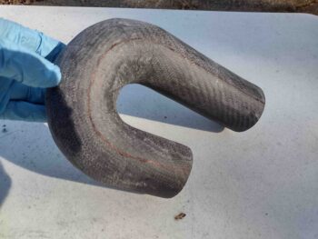
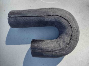
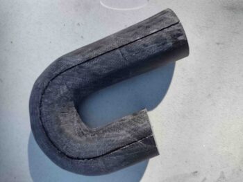
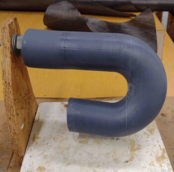
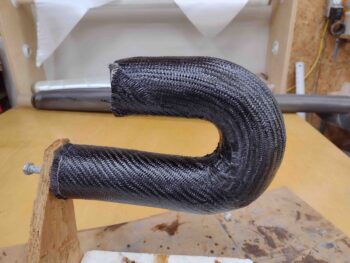
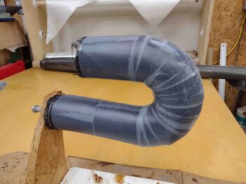
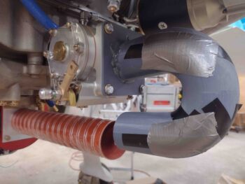
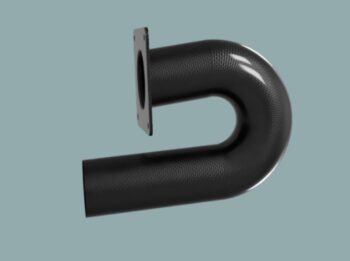
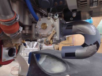
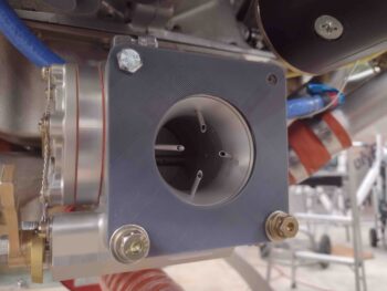
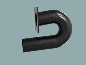
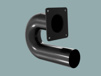
My intended goal for the day was to finalize the configuration of the air induction tube attached to the aft side of the fuel injection servo, but that didn’t happen.

First off, I will note that although I have a lot of pics in this post of the fuel injection flow divider mounting bracket versions and test installs, I really didn’t spend that much time working on it.

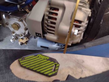
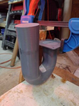
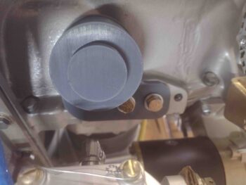
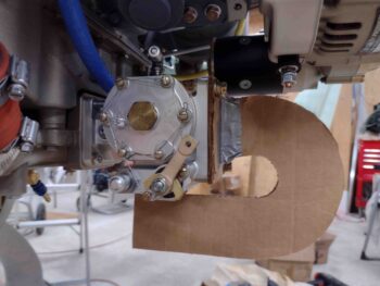
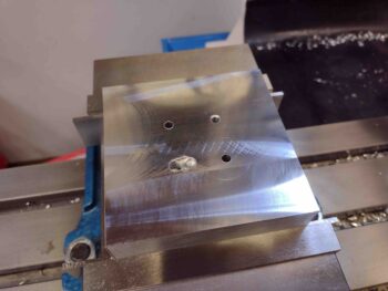
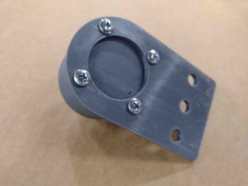
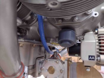
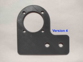
I started off spending about 15 minutes installing my modified design of the fuel injection flow divider mounting bracket.

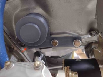
This bracket version flushed out a couple of issues right off the bat.  First, in the pic above note the red arrow which is where the bracket is pressed up against the bottom surface of the engine.  The bracket is too long/wide and needs to be shortened/narrowed to move it aft on the motor (right in the pic).

Also, the third bolt hole (aft/right side) was contaminated with paint or something, and I had to use a tap to try to clear it out.  I got about 3/8″ in but hit something that was making it impossible, with the access I had at this point, to get enough torque on the tap to break through.  Thus, since this is not the main priority I simply punted and decided to go with the forward (left side) two bolts and press on.

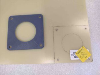
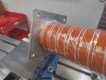
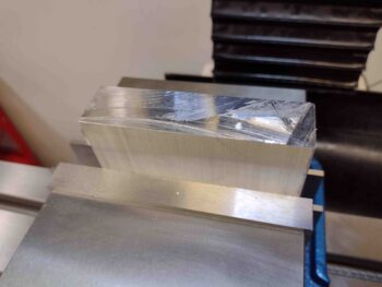
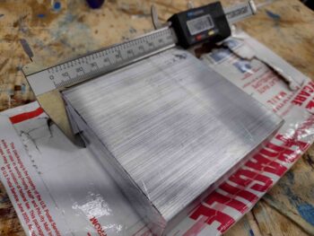
Today was the second of two beautiful days with warmer weather in the low 60’s.  I decided to get some outside household tasks knocked out, which burned up a few good hours.  But while it was still light out (and warm!) I took the opportunity to cut my recently delivered block of 6061 aluminum that I ordered for the RAM air can SCEET tubing attachment adapter bracket.

This chunk of 6061 is 1″ thick x 4″ x  6″.  The SCEET adapter bracket needs to be 4″ x 4″ square, so I’m going to trim down the long side to just over 4″ wide.

To be specific, I marked my cut line at just a hair over 4″, at 4.07″.  Normally I would use my horizontal band saw to cut this but it is not cutting straight lines and I didn’t feel like spending an hour or two messing around with it to get it aligned properly… which I probably should have, but I’m feeling way behind the power curve time-wise with all the engine/cowling challenges that I’m currently dealing with.  So I used my chop saw, which I know cuts straight… albeit the blade has a much wider kerf.

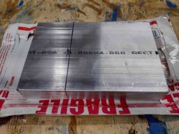
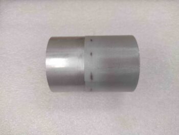
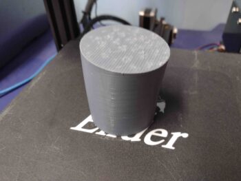
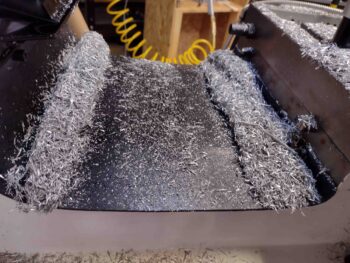
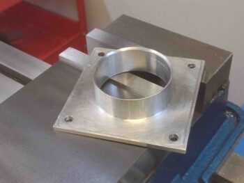
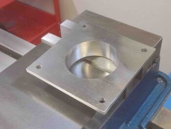
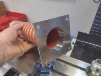
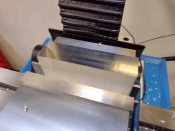
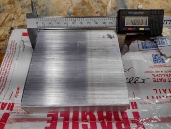
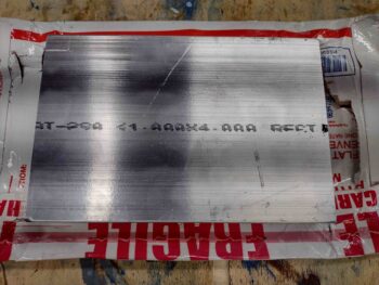
Here’s the end result of my 6061 stock trimming.  The final width turned out to be right around 4.093″ wide, just a wee bit wider than the cut line I marked.  Of course I’d much rather be 0.09″ over than under 4″… so pretty darn good in my book!

Pic #2 (right) shows the cut end… a little rough but not bad.  All but a ~1/4″ of this edge will be removed anyway!

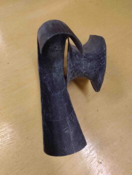
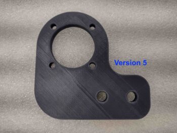
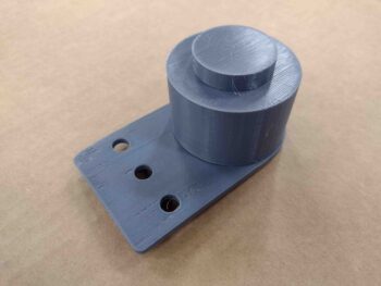
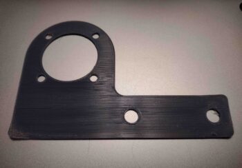
Again, I spent maybe 10 minutes tweaking my Fusion 360 CAD file to create the latest mod, Version 3, of the fuel flow spider mounting bracket… which I then kicked off the 3D print to be whirring away while I trimmed the 6061 stock above.

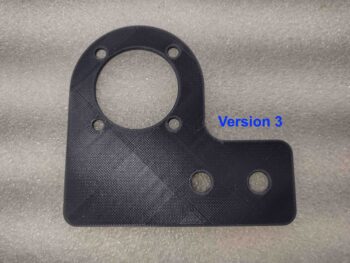
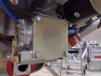
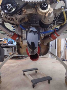
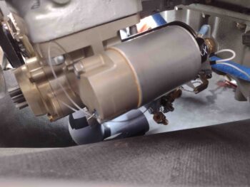
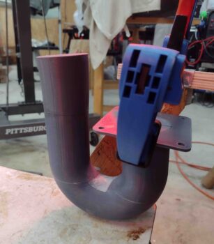
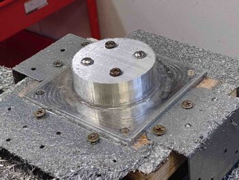
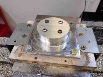
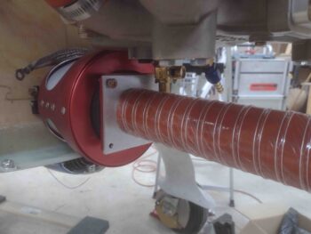
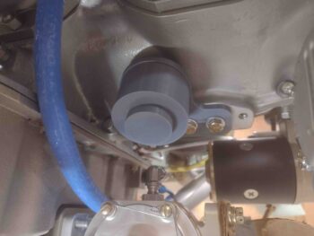
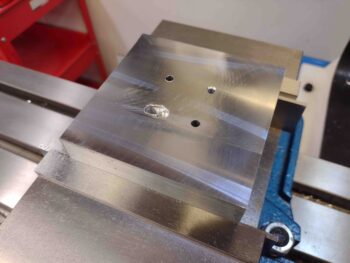
I pulled the old Version 2 bracket off and put the new Version 3 bracket on… As Maxwell Smart (most of you are hopefully “mature” enough to remember him) from “Get Smart” used to say, “Missed it by that much!

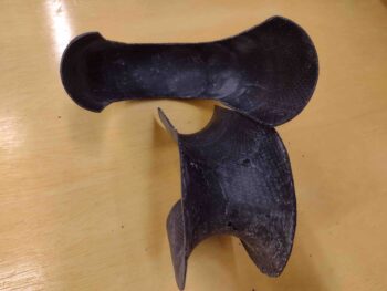
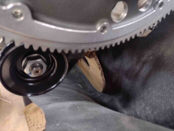
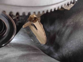
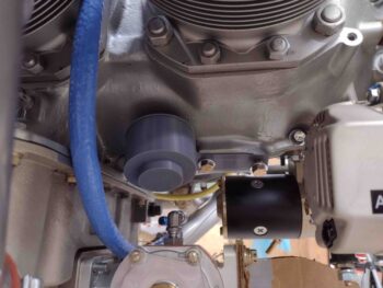
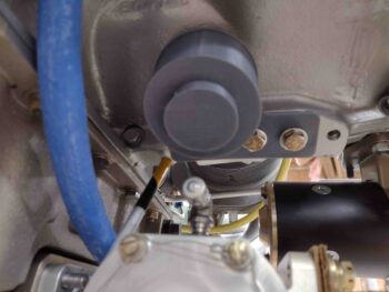
Again, the bracket is encroaching on that one edge on the bottom center line of the engine by literally around 1/16″ … so close!  I’m using the yellow-tipped pointer to ID the area of interference.

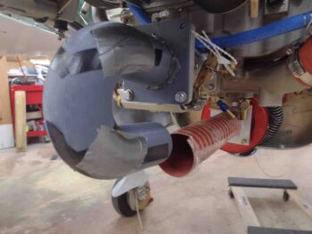
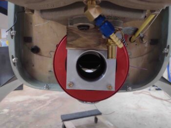
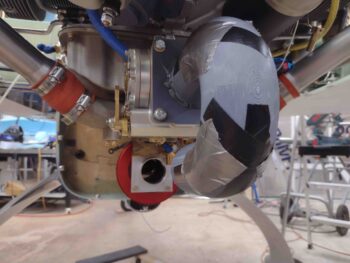
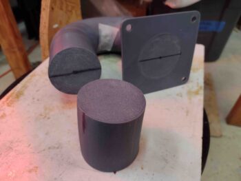
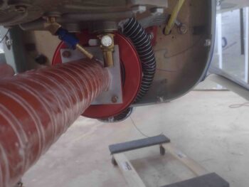
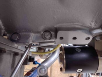
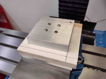
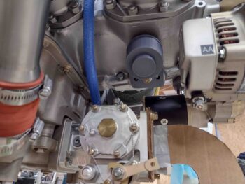
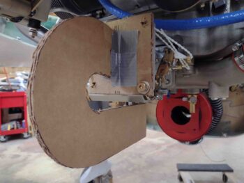
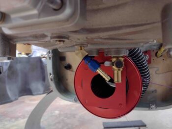
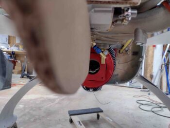
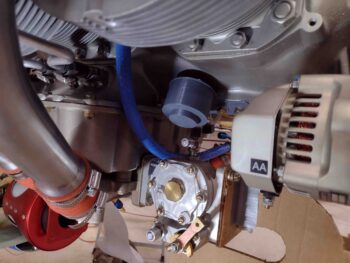
Here’s a wider angle shot to show how the fuel flow divider will look installed on the underside of the engine (IF and when I choose to move it down there).

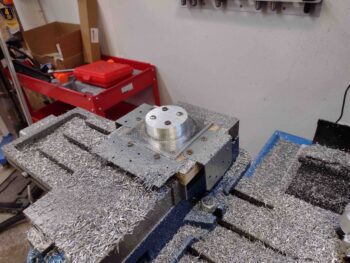
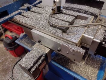
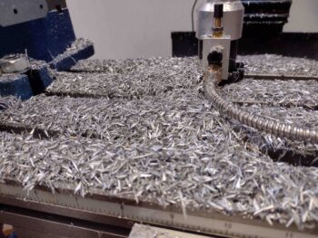
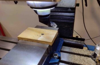
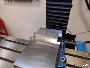
The time lapse between the above pic and the one below is about 4-5 hours.  I cut more wood outside on the table saw for the mounting base to machine the 6061 aluminum stock that will be the RAM air can SCEET tubing attachment adapter bracket.

I then went to do some test cuts to ensure the alignment was good on the milling machine when I hit a wall regarding the Fusion 360 CAM post processing software.  Apparently at some point getting back online and starting to use my Fusion 360 software involved them updating my software, which changed the parameters and profile of my milling machine, lathe and plasma cutting table.

Apparently their lovely “upgrades” and “improvements” hit after I machined the wood end plugs for the rudder return springs.  This evening I couldn’t get the Fusion 360 CAM software to produce the post processing files I need to tell the milling machine’s Acorn control software how to machine the part.  I finally got some post processing files out of it, but they still aren’t 100% and seamless as before.

It is probably impossible to convey the intensity or level of my being pissed off.  Having worked in the IT/communications field for half my military career, I dealt with geeks all the time wanting to change things “for the better” with no underlying driving requirements… which it seems this is exactly what the cell phone, computer OS and these Fusion 360 geek assholes seem to do with reckless abandon.  My cell phone camera being a perfect example… if it works, don’t mess with it!

Rant over… partially.

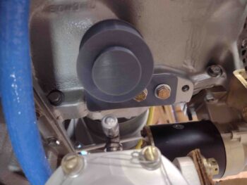
I then tweaked the fuel flow divider mounting bracket by moving the bolt mounting holes forward (to the left) by 0.15″.  I then trimmed the right edge by the same 0.15″.

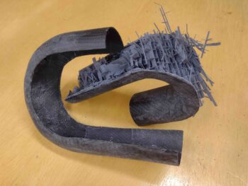
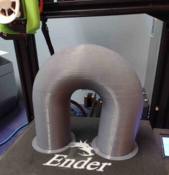
Perhaps you noticed that my last two 3D prints look much better than the previous ones, with the print lines running diagonally on the part vs straight across? That I’m not getting any edges curling up?  This is due to me updating my Cura slicing software a while back and it wiping out all my slicing profiles for PETG and PLA.  Yep, more geeks at work… helping “improve” things.

Well, my fault I guess for updating the software.  Of course I have screenshots of my profiles, but there are a dozen screens and countless parameters… so I am slowly dialing in my old parameters that actually worked.  Much as I am in the process of doing with Fusion 360. And to new “improved” versions of these softwares and their updates?  From here on out I need to just simply learn to say “No!” (although Fusion 360 is mostly cloud based so no opting out).

. . . . I warned you!  I’m pissed.

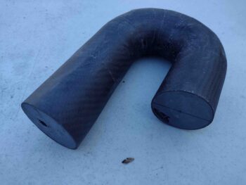
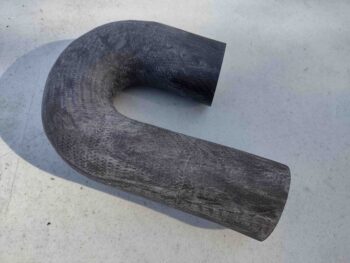
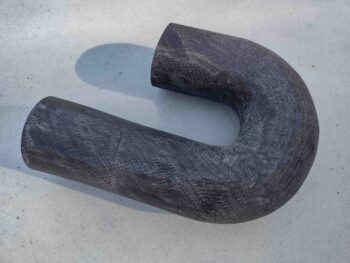
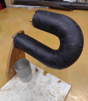
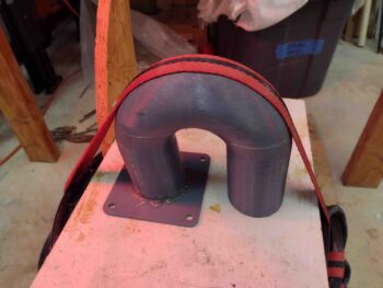
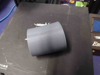
Tomorrow I’ll continue to work on dialing in my CAM post processing software to get the RAM air can SCEET adapter machined.  Then onto finalizing my air induction tube to get it glassed and mounted as well.

Chapter 23 – Induct, induct, induct

I had to run some errands this morning so I grabbed some hardware for the fuel injection flow divider and mounting bracket.

After I returned home, I then mounted the fuel flow divider to the mounting bracket with 10-24 screws.

With the bottom cowling off, I then went to test mount/fit the 3D-printed fuel flow divider and bracket assembly.  Immediately I realized that in my rush job to model the mounting bracket up in CAD that I had messed up the dimensions for the actual attach portion of the bracket, which should have been a bit wider than the round portion up higher where the actual flow divider attaches.  With the bracket’s bolt holes misaligned, I went ahead and mounted it using the center hole.

The setup was definitely good enough though to allow me to assess the possible mounting of the fuel injection flow divider on the underside of the engine.  I decided that I would want the flow divider as close to the original fuselage station as it is mounted up top.  Clearly as far forward would be better for mitigating any negative aft CG impact.  Plus, the more equidistant and centrally located the flow divider should translate into shorter lengths of fuel injection lines required.

Jumping ahead a few hours, I spent about 10 minutes revising my fuel injection flow divider mounting bracket to offset the flow divider forward while still using the same engine mounting pad.  I figured two hefty 5/16″ bolts should hold it fine, so I eliminated the center bolt hole, facilitating easier install, less cost and less weight.  Tomorrow I’ll check out this new design.

I then got onto trimming and testing out Version 4 of my air induction 180º intake tube. After looking at it for a good little bit, I decided to trim the front tube at the intersection with the fuel injection aft face at a slight angle, to get the in-rushing air to enter in a bit straighter.  I cut a line with 5/32″ off the top and 1/4″ off the bottom.

I then remounted the Version 4 intake tube onto the aft face of the FI servo.

And once again remounted the bottom cowling.  As I suspected, I really didn’t get much from my trim.  I noted with the angle that the tube attaches to the aft face of the servo, I have 2 opposing actions going on when I trim the front of the tube to push the entire assembly forward:  A) Trimming/moving the tube forward pushes further forward in the “chute” that is the bottom of the cowling, that drops down as it goes forward.  That’s a good thing, but the drop is a bit shallow.

However, action B) is that with the angle of the top part of intake tube curving somewhat sharply upwards as it goes aft, when I trim the front of it to push the entire assembly forward, I’m also dropping it down a hair as well.

So the question is, which action is making the most difference and winning out?

Using my 0.27″ cardboard spacer, I could see it was definitely easier to slide in and out under the cardboard bottom edge, but that really only gives me more clearance of maybe 0.01″ to max maybe 0.02″ more.

The good news is that my air is entering the servo a bit straighter, but at slightly less total straight distance, and I didn’t really gain much as far as clearance.  I’ll have to ponder on this a lot more to see if any panaceas jump out at me.

Meanwhile, I received my respective ACS and McMaster-Carr orders today, which allowed me to assembly the components for my Sniffle Valve assembly.  Years ago, when my engine builder warned me about installing a Sniffle Valve, I did some research to get as much info as I could.  I ran across Matt’s RV-7 build blog and noted how he angled his Sniffle Valve to get around an exhaust pipe.

Well, I may need to angle mine to get around the 2.5″ SCEET duct that will connect the RAM air can to the fuel injection servo.  Regardless if I angle it or not, I will need to attach a drain tube to it to exit out the bottom of the cowling.

I started by gathering up all my newly acquired components that will make up the Sniffle Valve assembly (left pic).  And then used my Dremel Tool to remove and shape a good bit of the material on the threaded barb fitting to allow it to fit inside the AN -4D fitting nut (right pic).

Here are all the Sniffle Valve component parts assembled.

I then test mounted the Sniffle Valve assembly into its port on the bottom of the cold air plenum.  Again, if there is enough clearance between the Sniffle Valve and the SCEET tubing, I may not need the 45º street elbow, but better to have it on hand just in case.

This shot might give a better perspective of how the Sniffle Valve can be angled to avoid the SCEET induction air tube.

I’ll further note that I also just received a barbed brass “Y” fitting that will tie the Sniffle valve runoff tube to the mechanical fuel pump overflow drain tube to then allow me to have only a single tube exiting out the bottom of the lower cowling/firewall flange.

I’ll continue working the air induction system and engine components install tomorrow.