Chapter 13/18 – Ancillaries

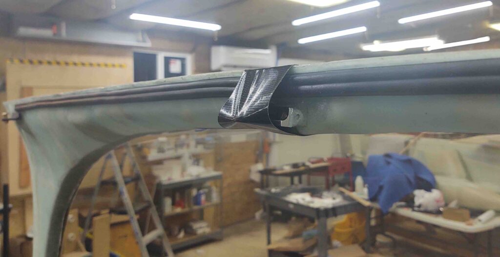
With pieces parts on order for the canopy latch handle, I figured I would knock out some canopy latch+ related ancillary tasks.  To really get the canopy latch completed I will need both the 3D printer and the milling machine online and operational, in that order.

Of course I worked on the milling machine install first because it involved using my hammer drill to make holes in the shop floor for the mill base’s securing bolts.  My neighbors aren’t that close, but that thing is still loud!

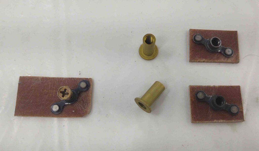
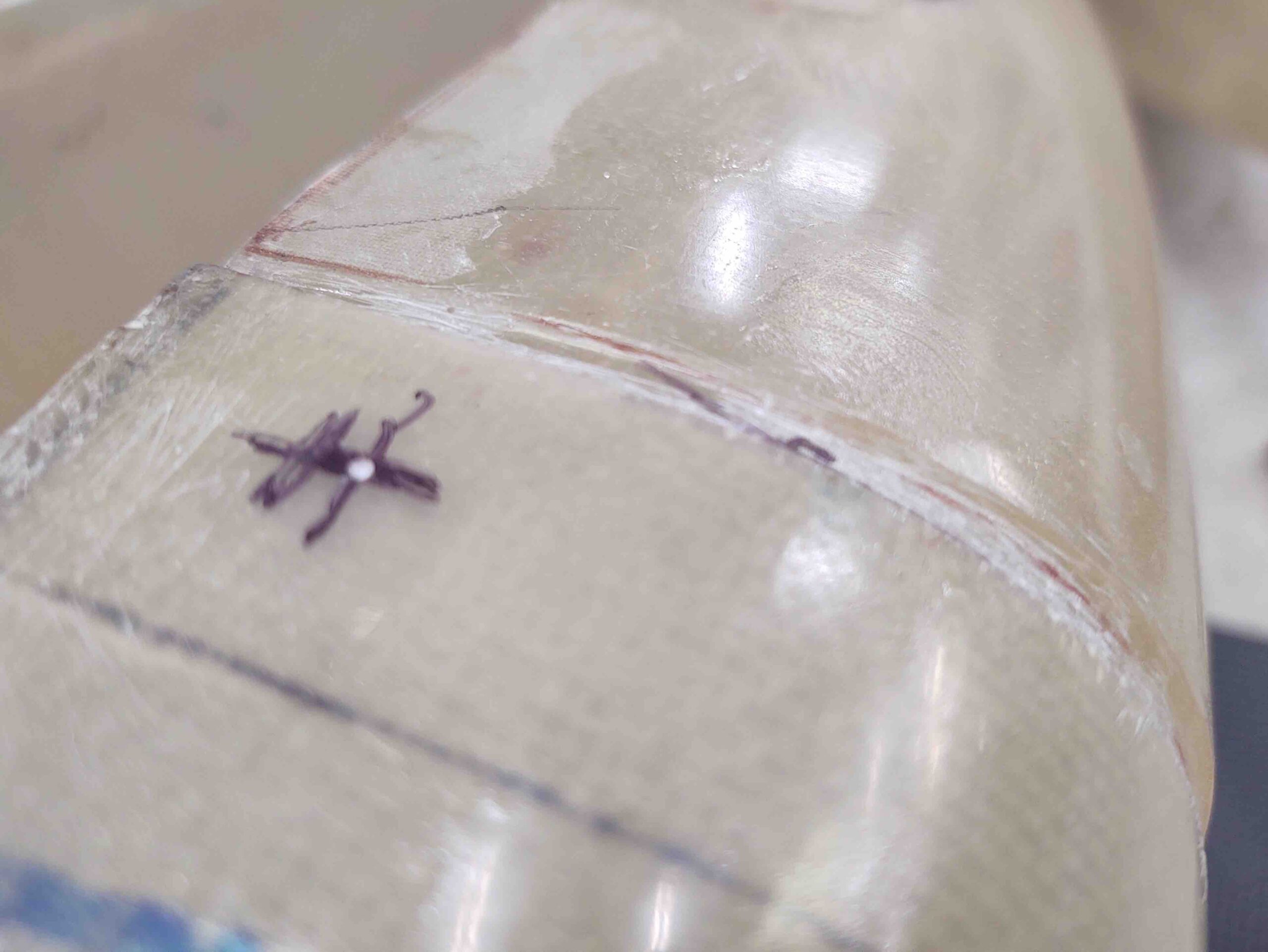
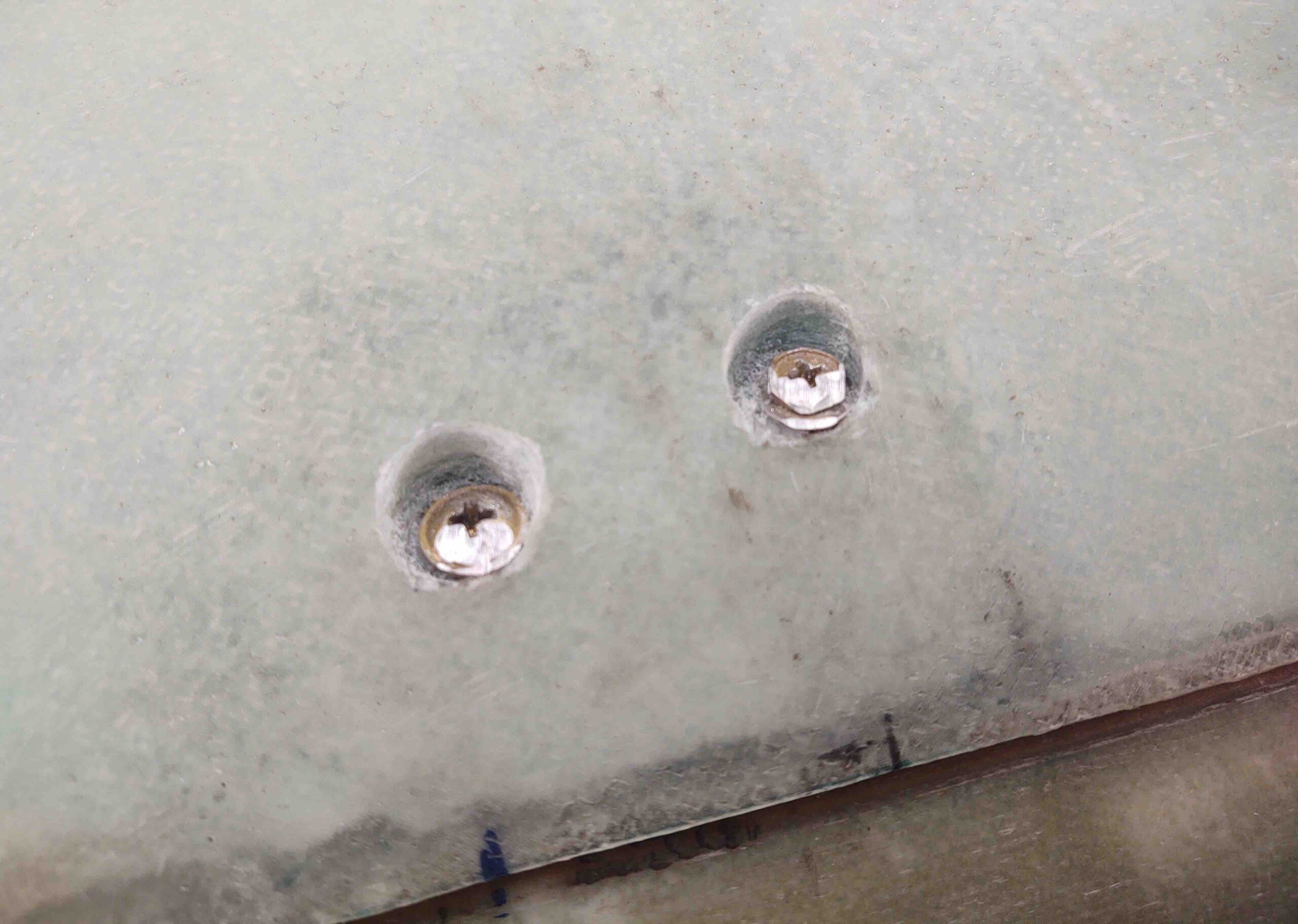
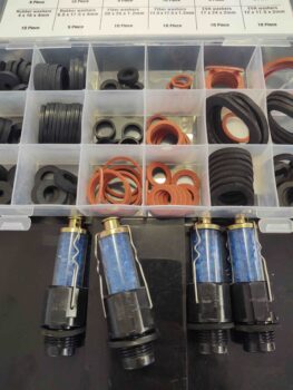
First up however was a trip downtown to Harbor Freight to pick up some ring gasket/seals (or flat O-rings) for the engine desiccant plugs.  These desiccant plugs are great for soaking up the moisture in the cylinders, but their design –especially for their price– leaves a little to be desired.  To keep the moisture out of the cylinder, as denoted by how long the desiccant stays blue, you need a fairly tight seal on the rubber ring gasket.  The problem is a decently firm torque deforms these rubber seals out of shape in too short of time [torque too much and you’ll bust one of these off in your spark plug hole… don’t ask me how I know!].

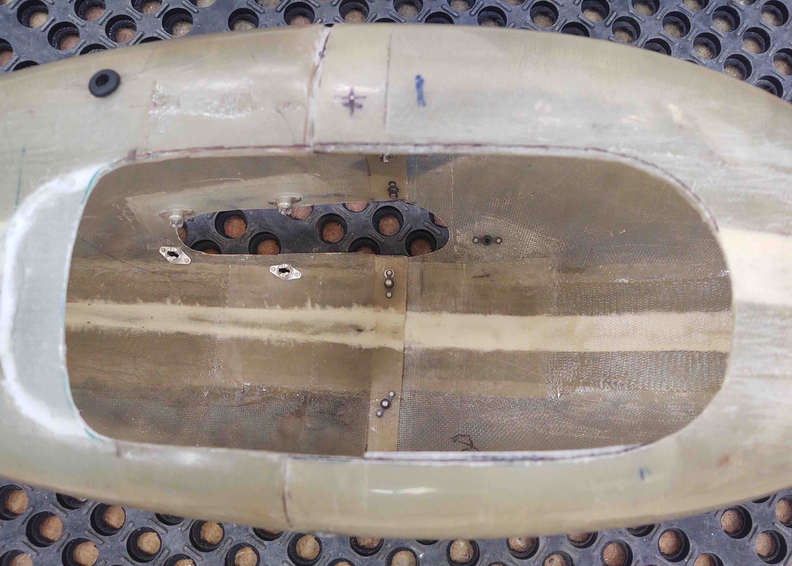
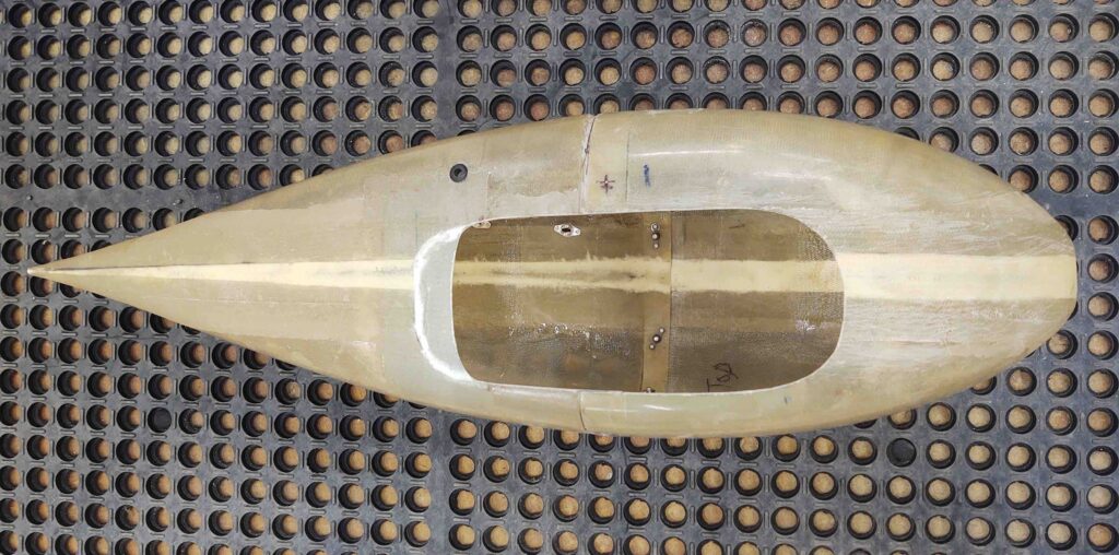
With new seals in hand I went back home and flipped the engine back upright.  I put the refreshed desiccant plugs back in the upper spark plug holes and hooked up the desiccant air dryer to the engine.  Task #1 complete.

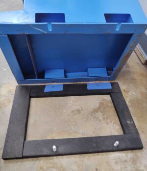
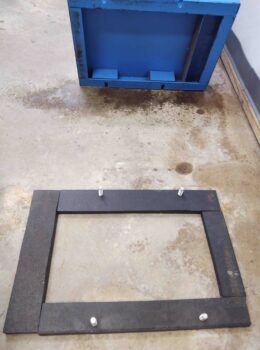
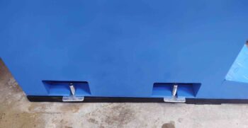
I then got to work on the mill base, first cutting the strips of very thick hard rubber that I’ll employ for vibration dampening for the mill.

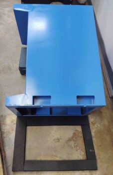
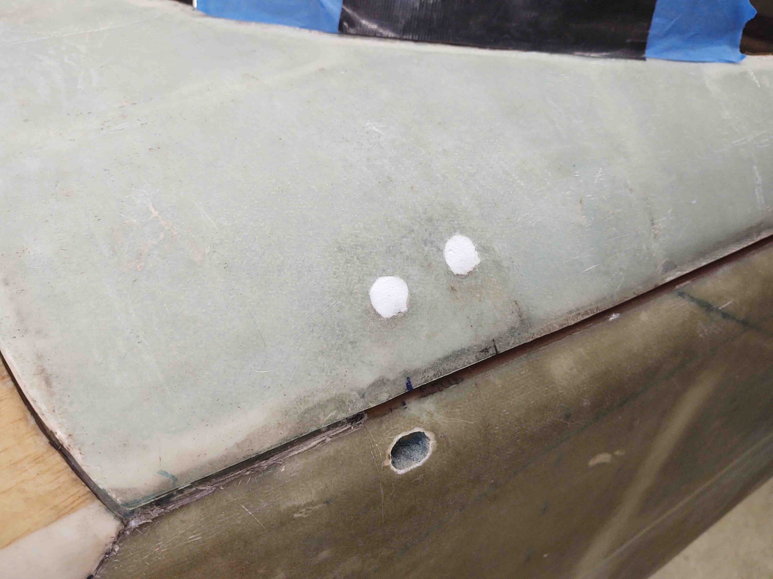
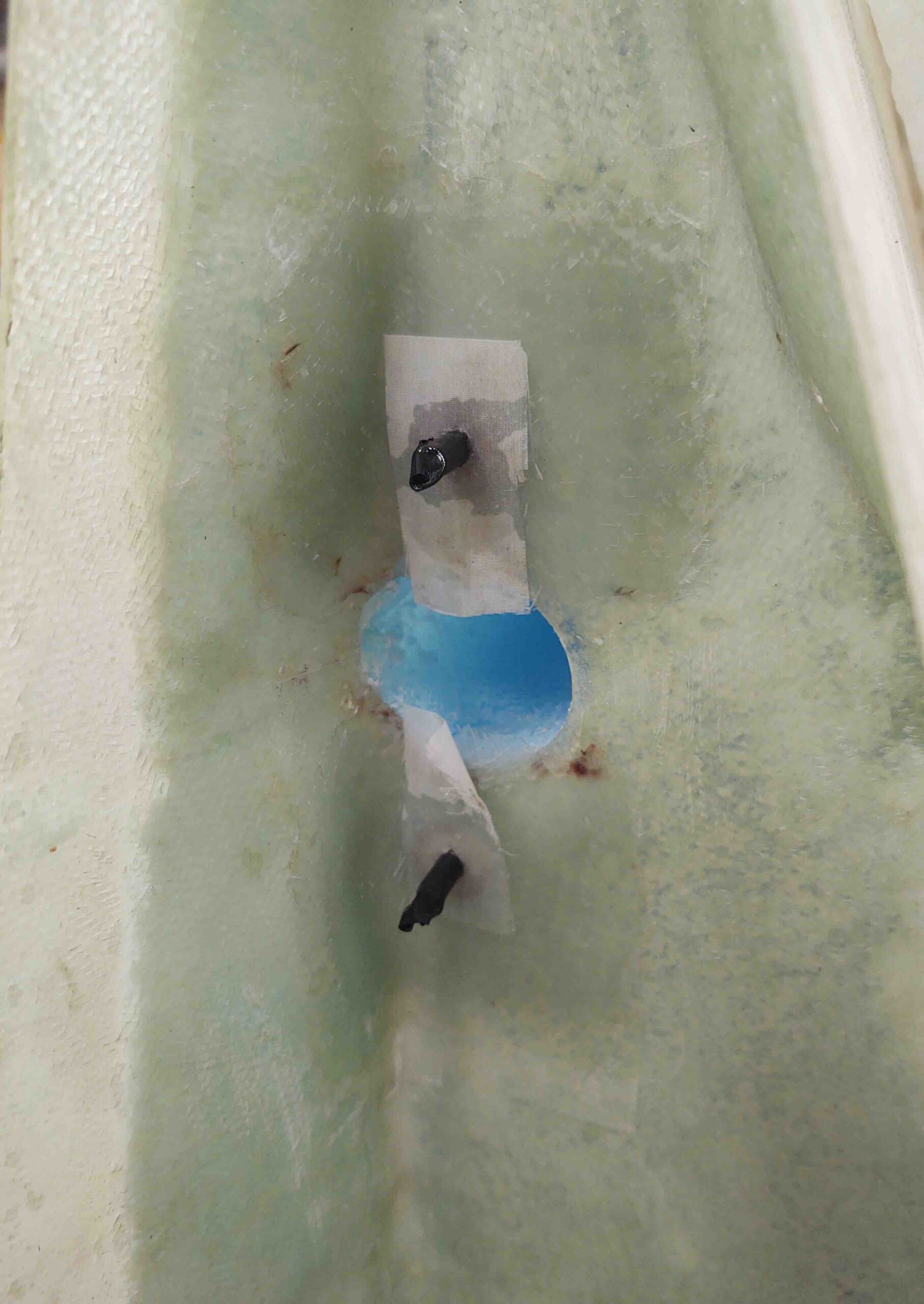
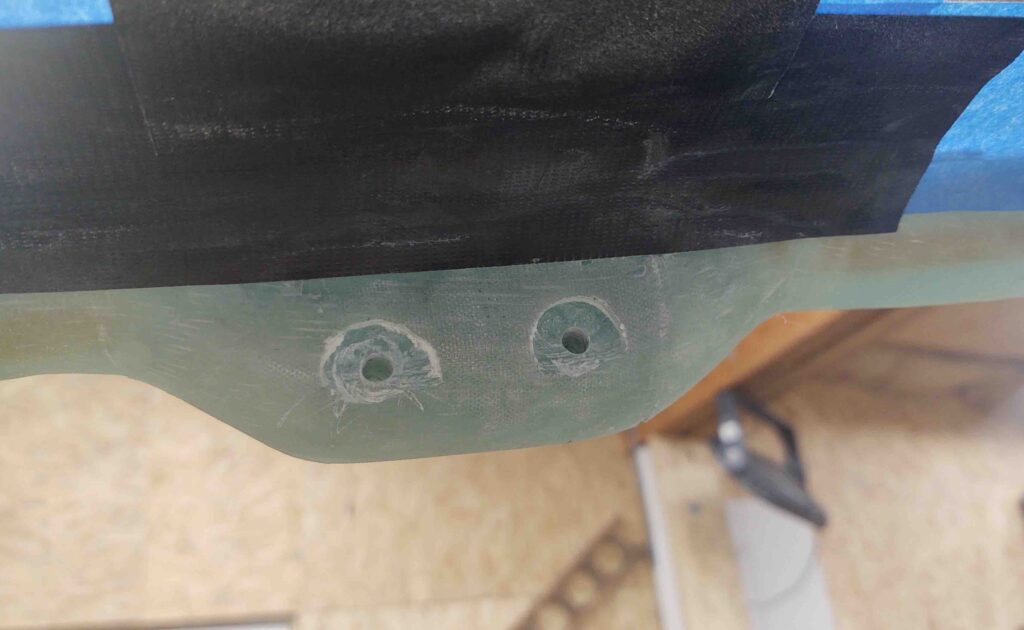
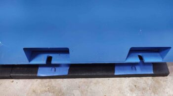
Here’s how the rubber base for the mill base looked on each side.  I added blue tape below each bolt attach point to mark the hole drill spots.


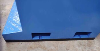
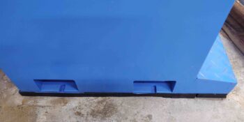
As you can see here.

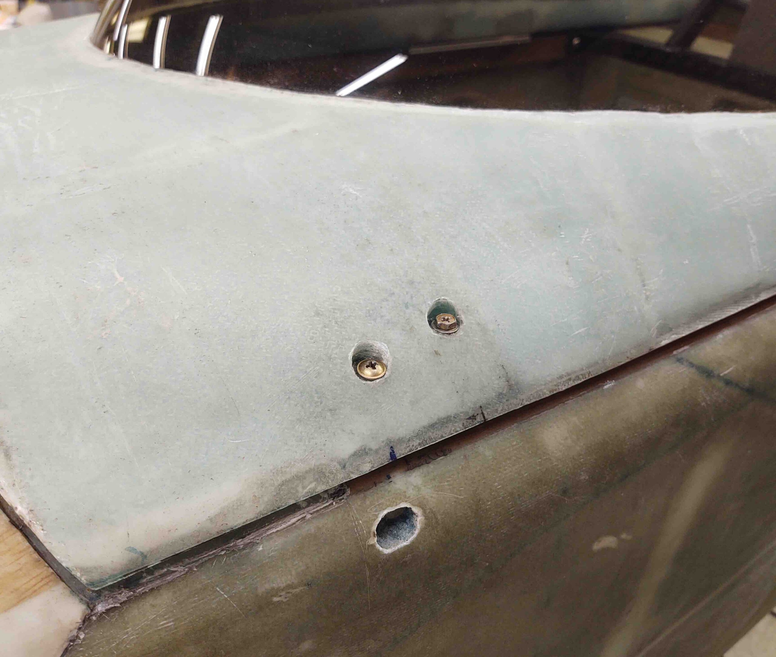
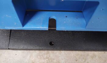
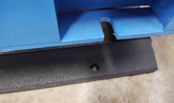
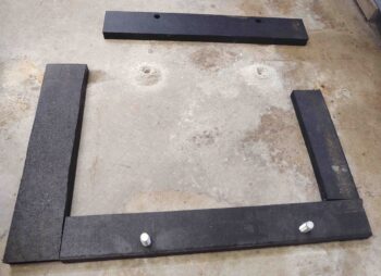
Here are the 2 holes drilled out on the right side.

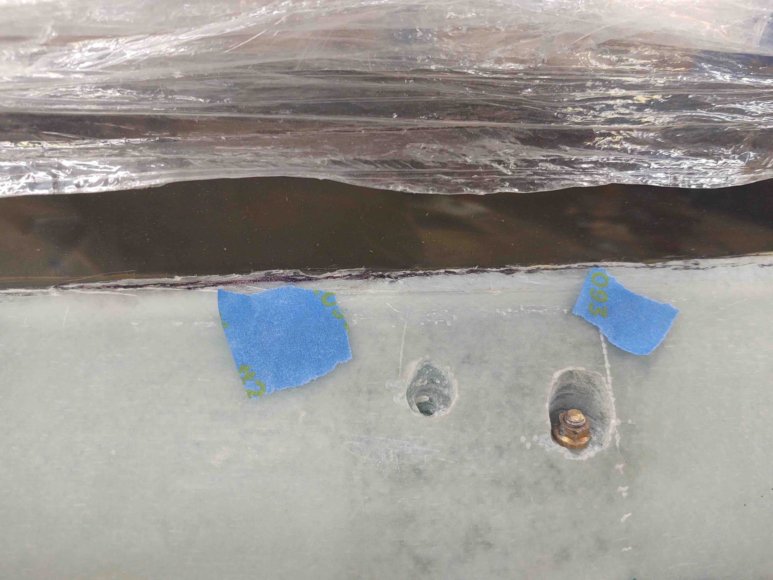
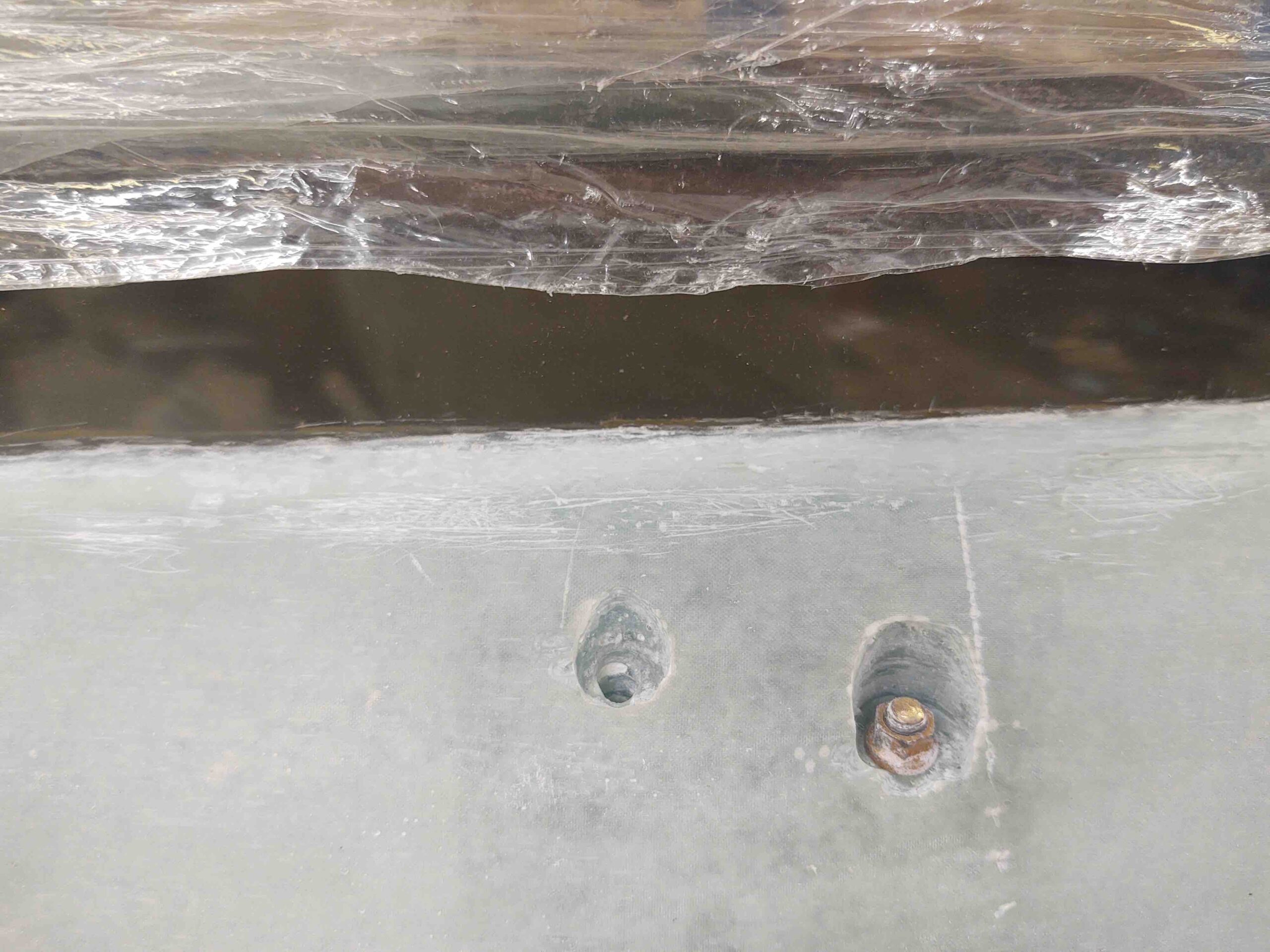
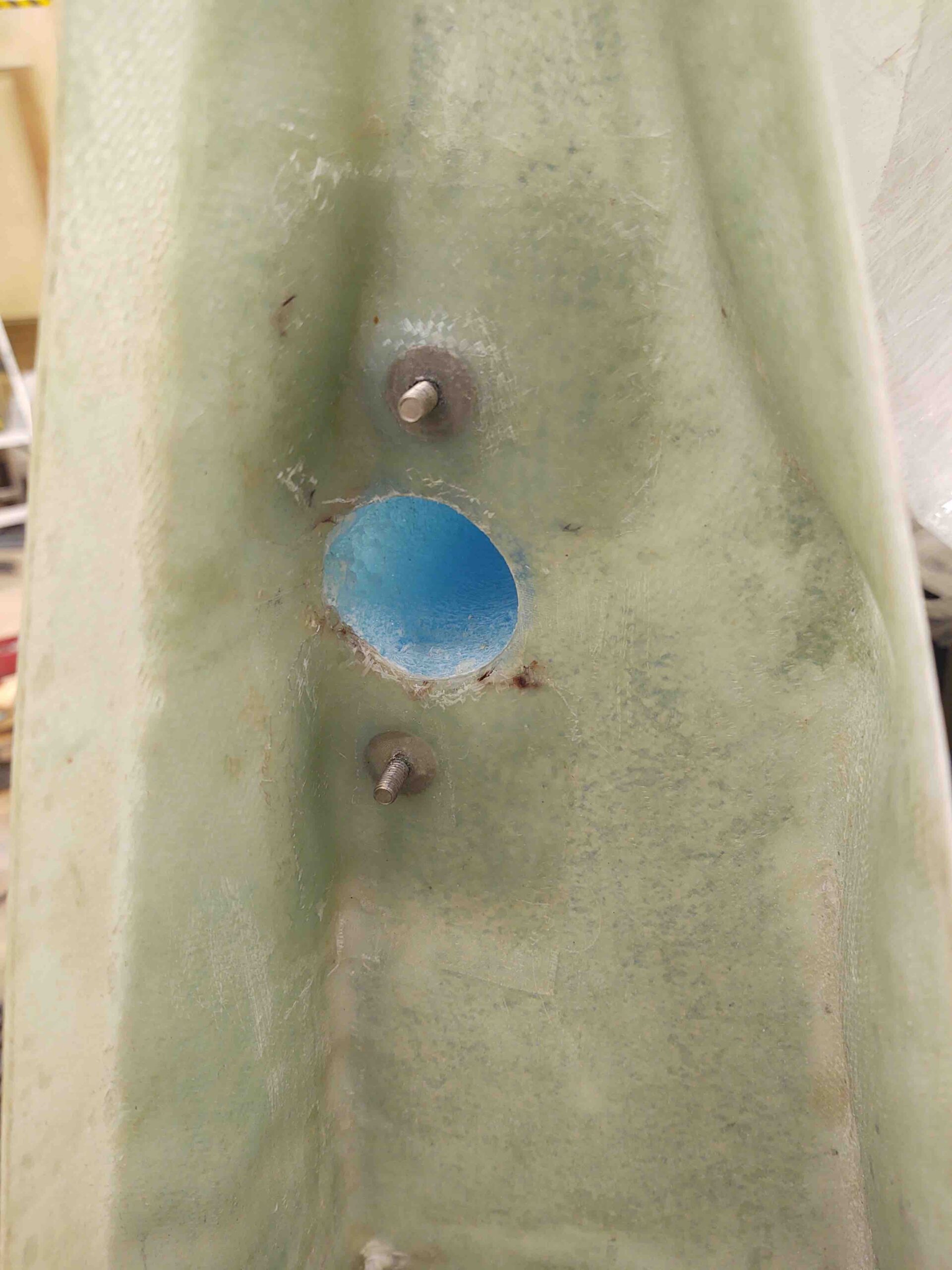
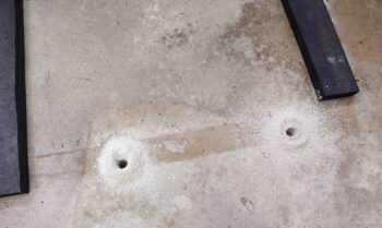
I then drilled nearly 3″ down into the concrete to create the holes for the threaded mounting studs.

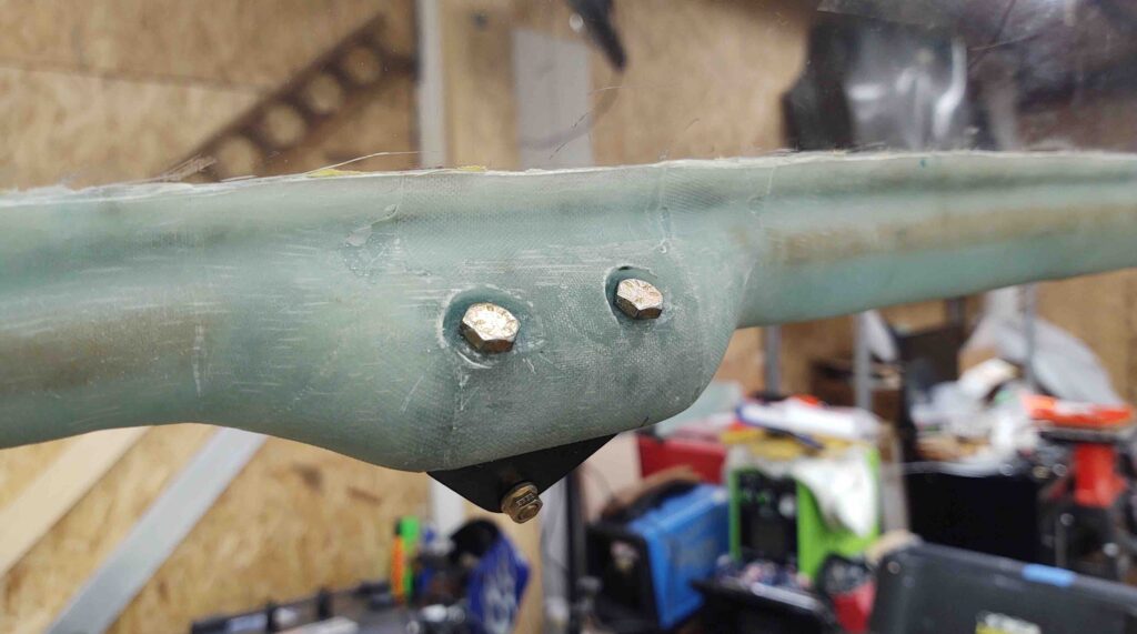
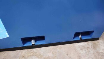
Which I then pounded into place.

A shot of them, one with nut & washer and the other bare.

I then (remarked) and drilled the other side.

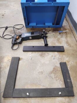
I included a shot of my old, gritty and raw hammer drill.  That thing will eat through anything!  As you can see I mounted the left side studs and the rubber base padding.


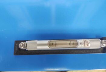
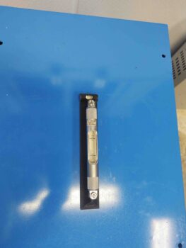
With the mill base in place, I then needed to level it.

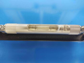
The first pic is the right-to-left level, way off.  I then put one metal coupon (leaning against level) on each left side mounting stud to get this result.

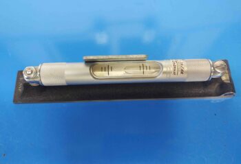
Metal coupons added to left side.

The front-to-back initial level was awful as well (my shop floor is really uneven!).

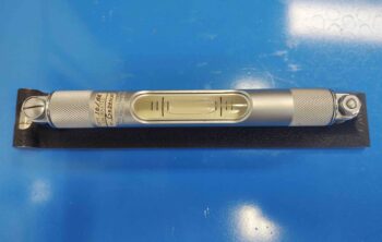
I went to grab some dinner, and these were the results I had for left-to-right and front-to-back levels before I took off.  Not bad, but I have two corners floating in midair that need a decent number of shims themselves… which I don’t have on hand.  I’ll buy some more tomorrow and continue on.

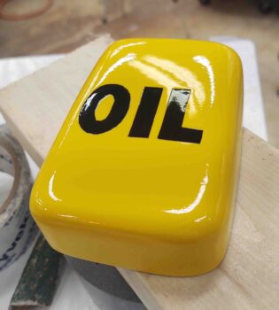
So, I told a bit of a fib just earlier.  I actually started off after the engine flip by quickly sanding the nose oil box that’s been sitting on my shop desktop for a good month now. I then hit it with 3 coats of clear total, at differently intervals as I was cutting the rubber strips to mount under the mill base.

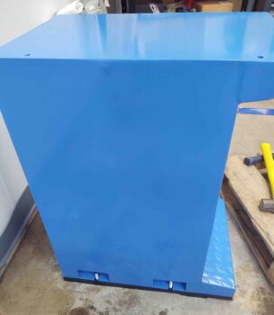
Here’s the clear coated nose oil box lid.  The box is no beauty queen, but it’s bright and eye-catching and will do the job.

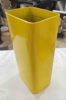
Here’s the actual box here.  Also with 3 coats of clear.  The coats aren’t as thick on the vertical base just because I didn’t want to risk runs.  I’ll wet sand this and buff it out a bit.

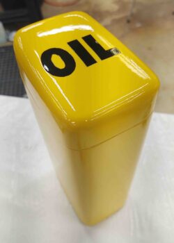
Here it is all together.  This oil box will hold a 1-quart bottle of oil nice and tightly with a little room at the top for a couple paper funnels and a rag or two.  I plan on mounting it about midway between the Napster bulkhead and the right rudder pedal.

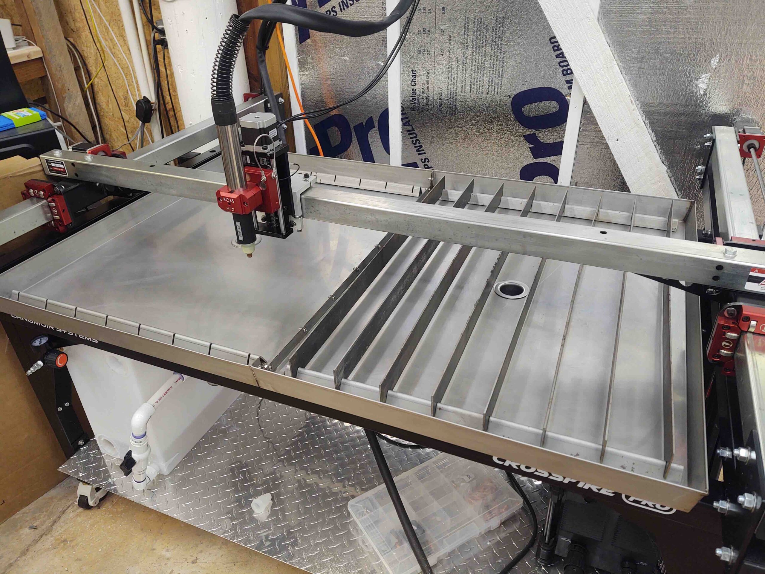
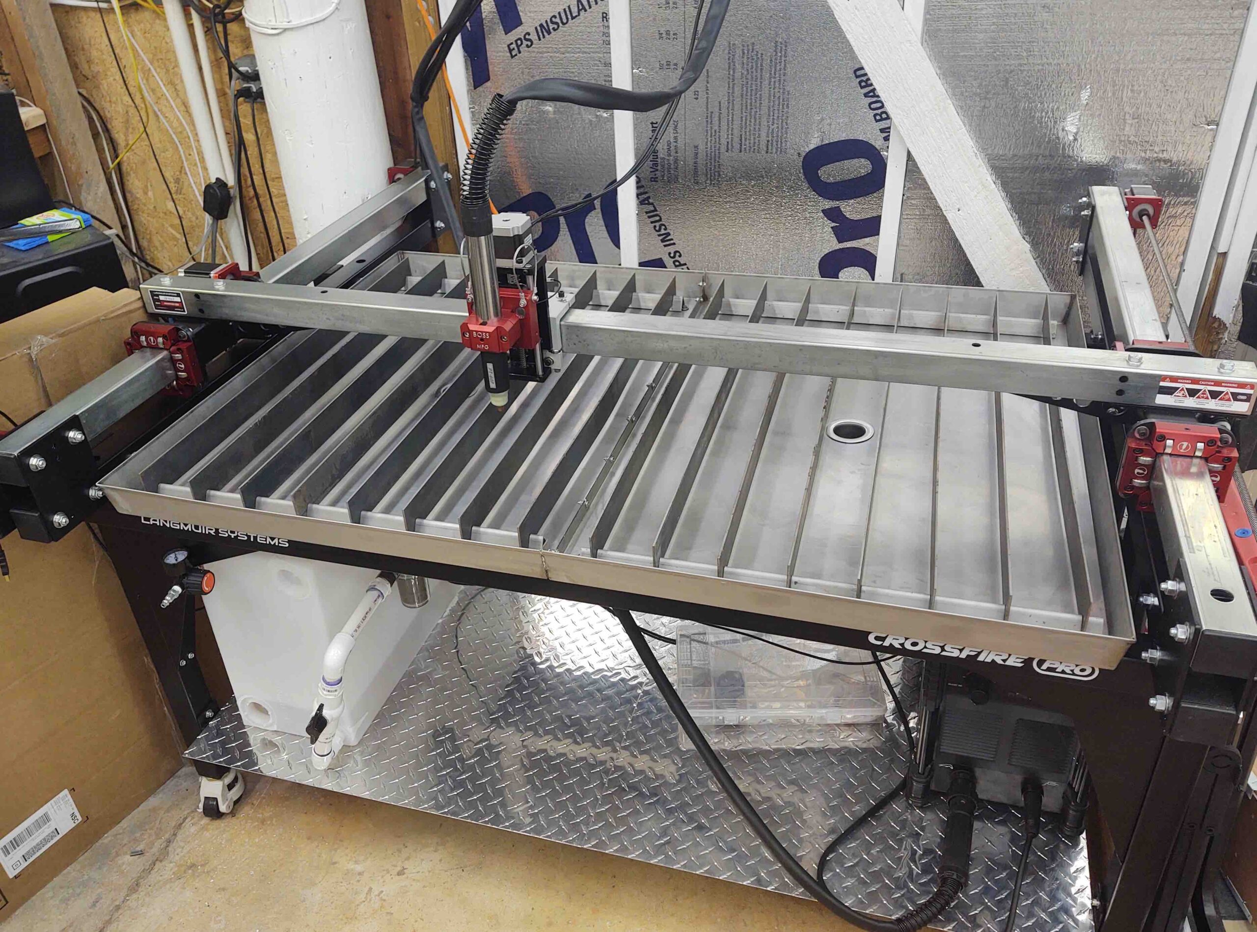
After I returned from dinner I got to work on my plasma cutter.

Last night on my first few cuts after a long time off using the plasma cutting table, the gremlins of it stopping mid-cut and losing plasma arc that I had fixed just after shortly getting it up and running had apparently returned.  And believe me, I was not happy.  The first run went fine, but the second and third tries had the job stopping at about mid-point.

Now, I did upgrade the firmware, so that might have been the cause… although of course it shouldn’t have been.  Frustrated, I hit the forum last night and realized they had finally provided a factory fix for this issue that has afflicted a significant number of new Crossfire Pro plasma cutting table owners.

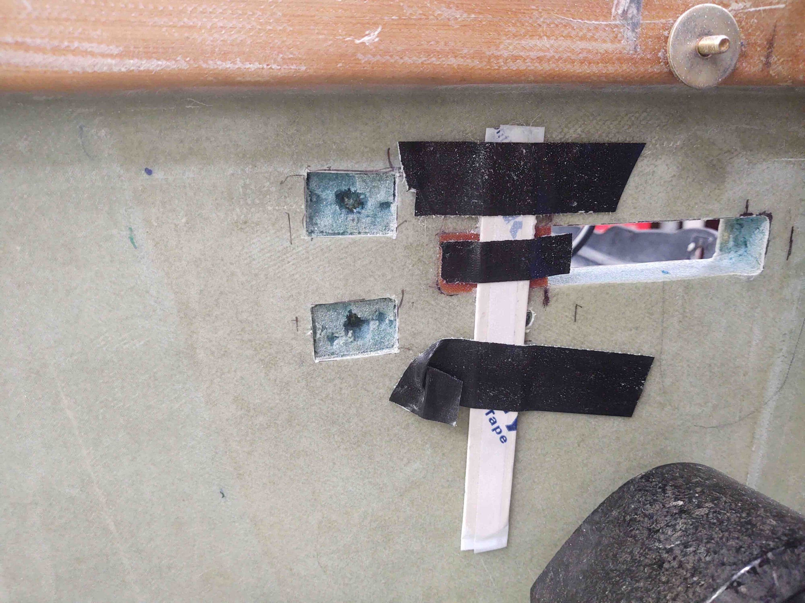
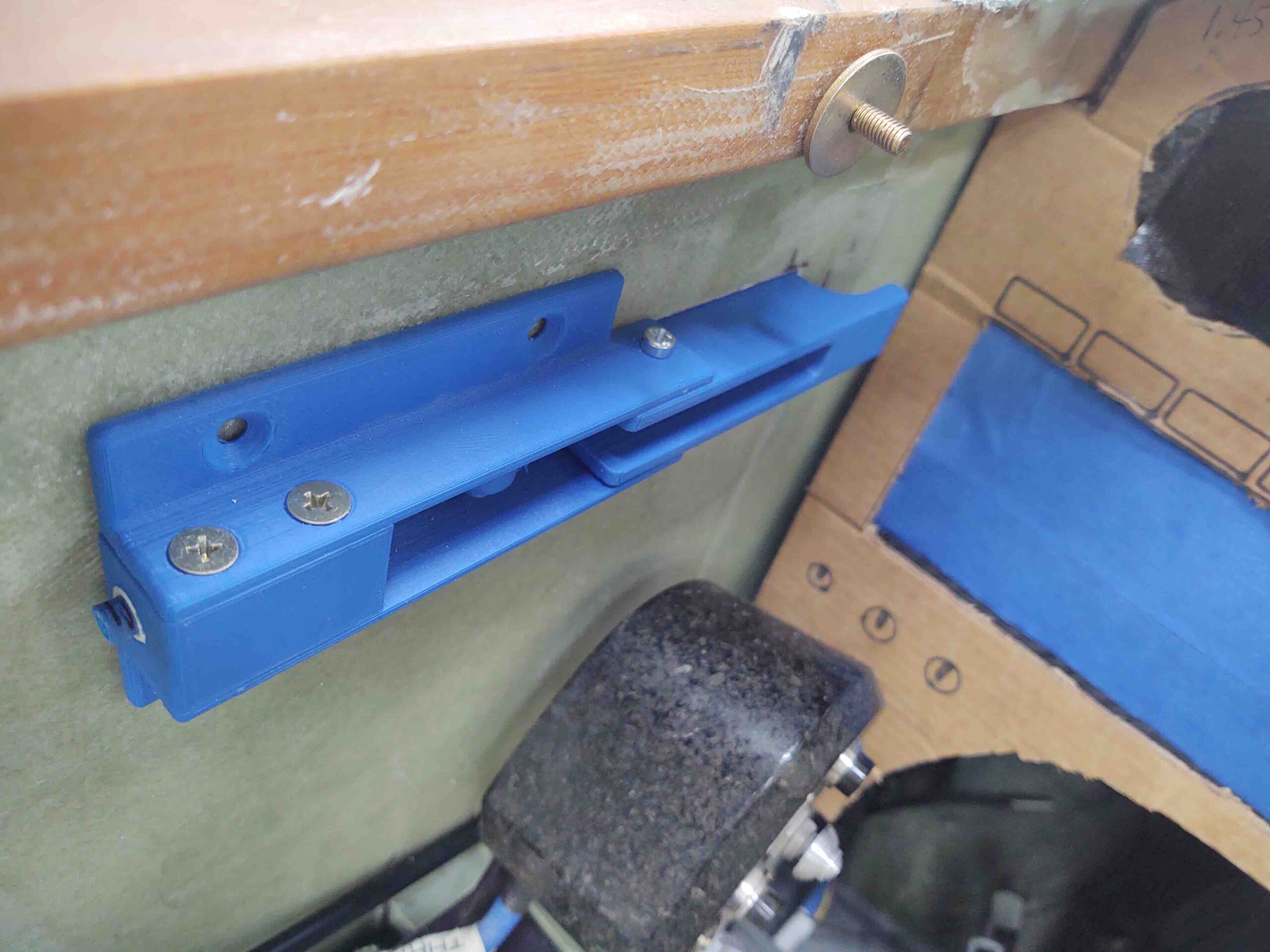
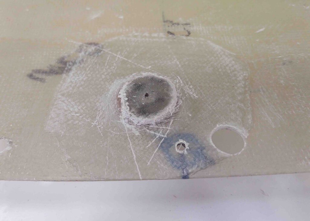
The fix required removing the main control circuit board.

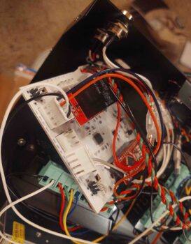
And then locating the tiny L1 Inductor.  Ironically, this little guy was supposed to mitigate the noise but apparently turned into quite the antenna, sucking all the noise in and wreaking havoc on the system (again, causing the plasma cutter to stop midway through a job).

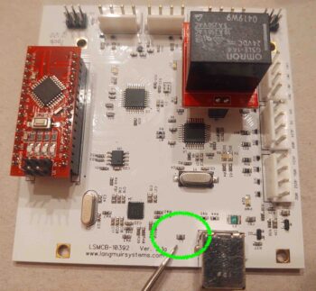
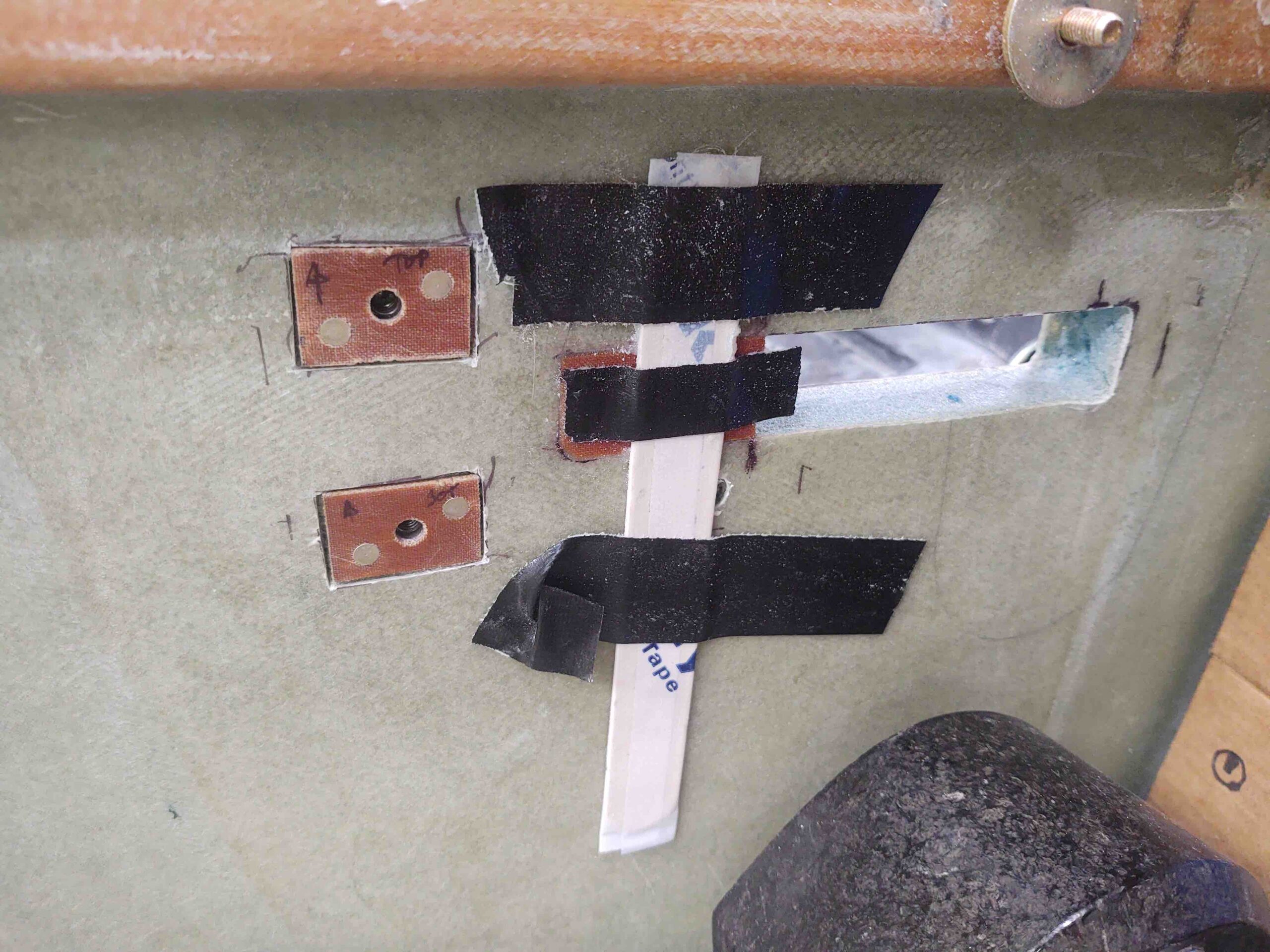
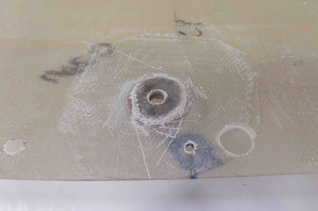
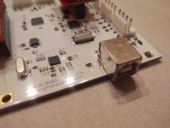
Then removing the offending L1 inductor off the PCB.

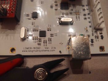
And creating a solder bridge by soldering the remaining nubs together with a very precise blob of solder!  (FYI – For the the owners that aren’t comfortable doing this they can send their board into Langmuir Systems and they’ll do it free of charge… also, the units currently shipping have been modified and have L1 removed).

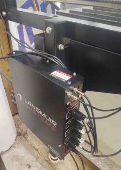
I then reassembled the control box, took it back out to the shop and remounted it.

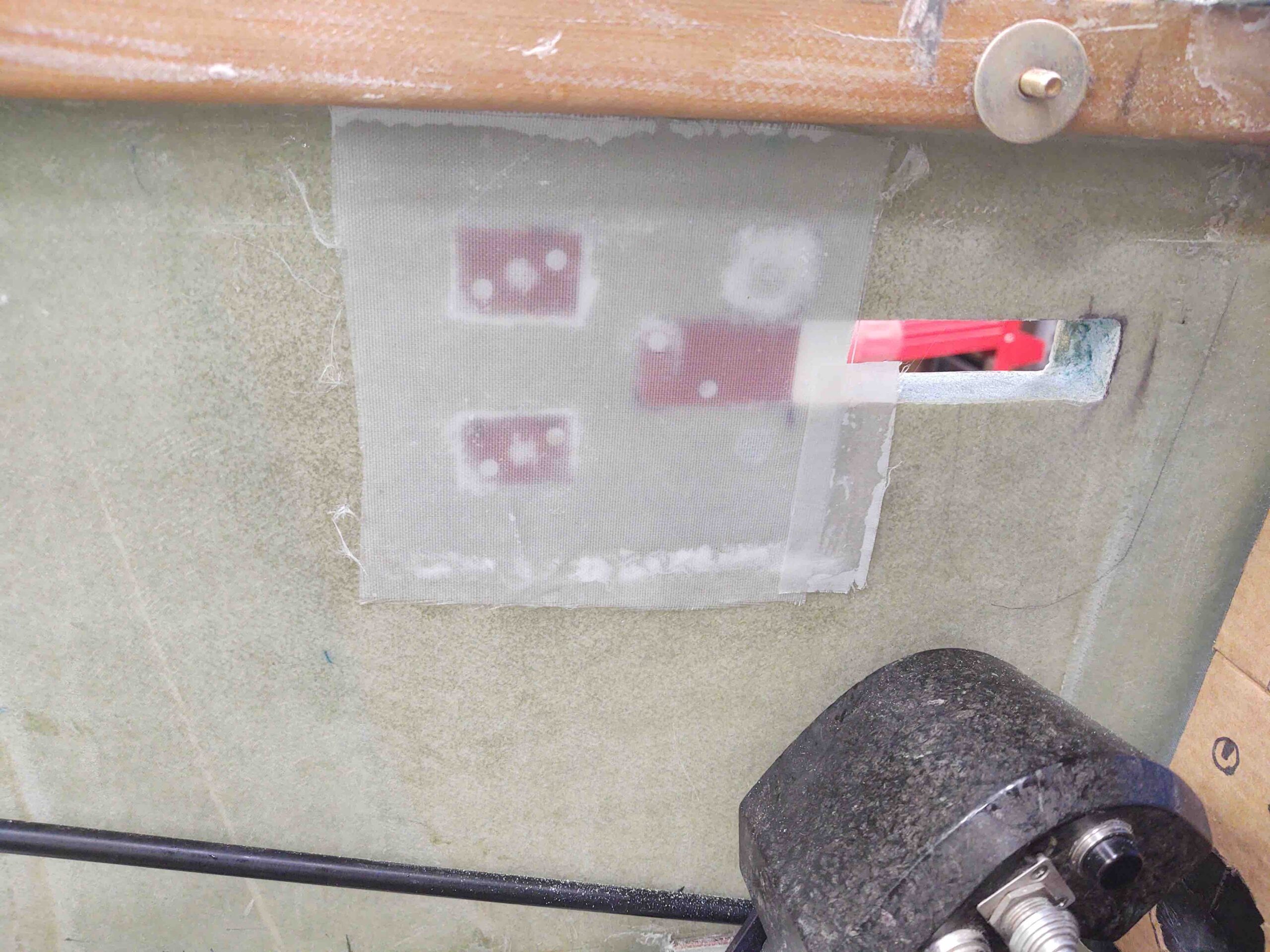
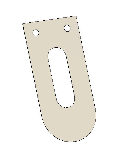
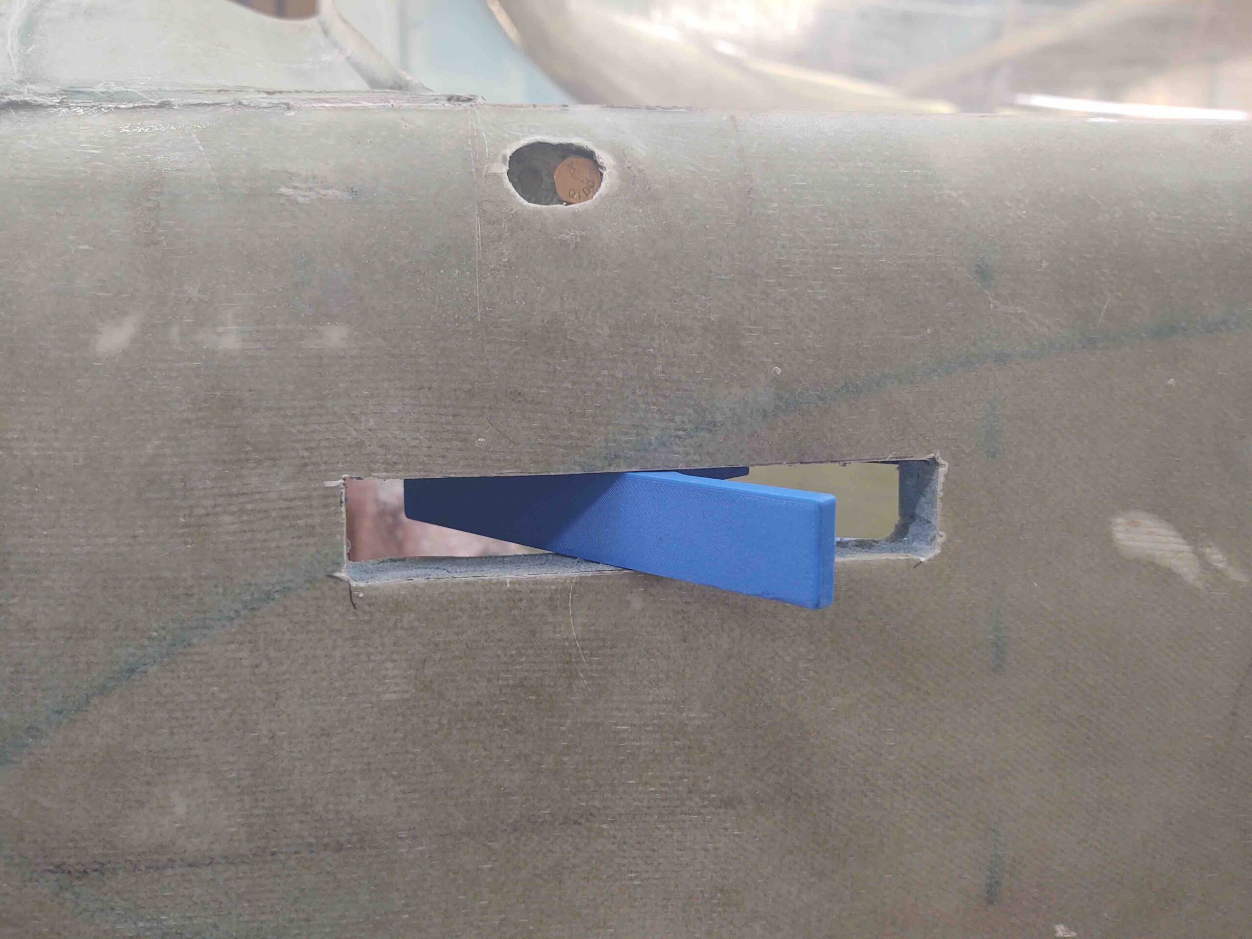
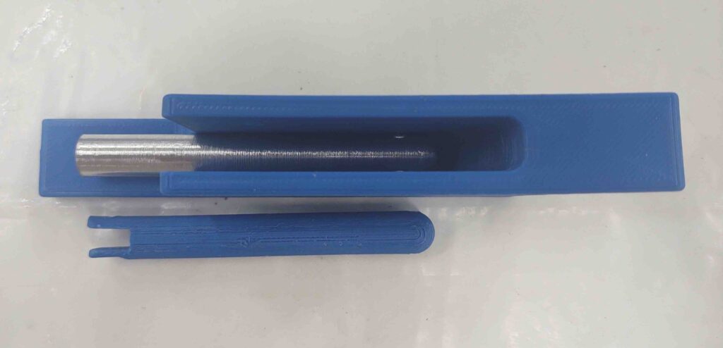
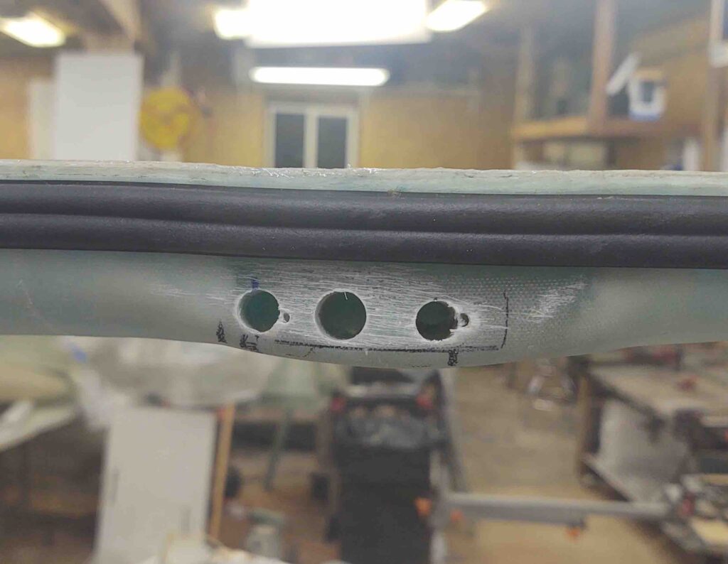
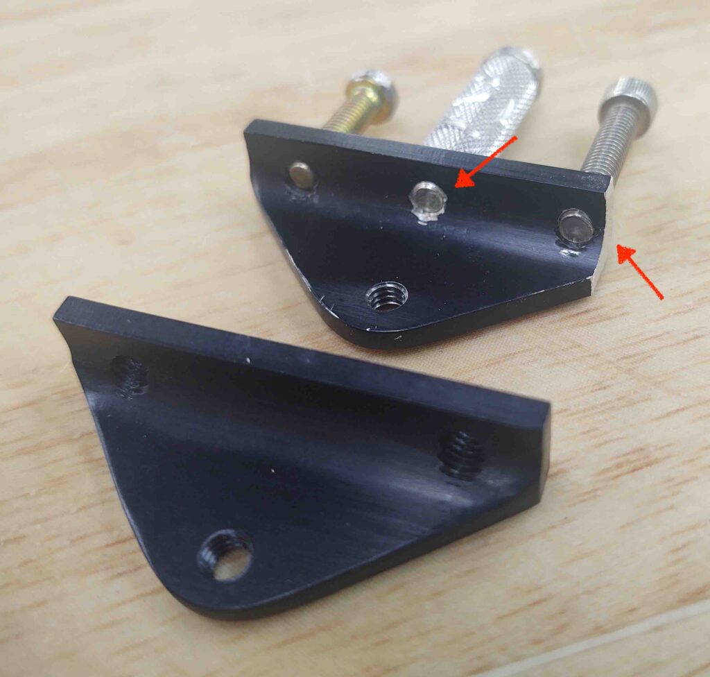
I’ll test it tomorrow by cutting another test LC-1 Canopy Safety Catch out of mild steel… before then cutting it from stainless steel stock.

And with that, I called it a night.

Now, I will be working on this ancillary stuff until I get my required bits for the canopy latch. It’s a good time to get the 3D printer back online, the plasma cutting table tweaked and the mill on its way to operational status.


Chapter 18 – Canopy latch system

Today I started out by pulling the peel ply and trimming the 2-ply BID layup securing the nutplates and one RivNut for the canopy latch handle mount. I then drilled out the glass covering the holes and dug out the protective plastic wrap (saran) that I had shoved in each one.

I then test mounted the handle assembly and it fit like a charm.

Although at first I thought I had my fore/aft mounting positioning off by about 0.050″, then I remembered the phenolic back plate needed a small U-shaped notch on the forward center edge of it to allow the handle linking rod to travel in unimpeded fashion.

A shot after the notch made in the phenolic back plate, and also the gray PETG triangular interconnecting plate back in play. Note the HEIM-4 rod-end connector, which I bought by mistake about 9 years ago and am just now putting to good use!

Here’s a shot of the front seat canopy latch system, sans the front hook and connecting rod (shown below).

And a couple of shots of the aft side in the GIB seat area.

I had to order a rod-end for the front latch hook rod so I won’t be able to truly test out the system for a few days yet. I’m kind of stepping out on a leap of faith here from just a few pics I have of an unknown Long-EZ’s –that BOTH Beagle and Terry Schubert couldn’t ID whose it was– setup with this central triangular connecting piece configuration. From what I can gather, it’s a type of mystical push-me/pull-me type setup where the rod force from the front hook and rear hooks play off of each other to push the rear hooks open while pulling the front hook open, then vice versa to close (rear pull, front push).

In addition to needing that rod-end connector (AKA “clevis”) to test out this setup, I also need to reprint the current blue PLA plastic handle with a more robust PETG or ABS (I should have that capability when I get the 3D printer back online) with the pivot bolt holes moved inboard about 1/8″. To dial in the canopy handle system I will keep both the aft triangular interconnect plate and front handle in plastic to modify as required. Once the configuration is good, I’ll drill/machine those parts in aluminum to finalize the canopy latch handle.

Chapter 18 – Gettin’ a handle on it

Today I got back to work on the canopy latch handle attachment to the left cockpit sidewall.

I started out with making up 3 nutplate assemblies: 2x #10 for AN3 bolts/screws (R side) and 1x for a #8 screw (L side). Two RivNuts will also be used to mount the handle assembly, both above and below the slot in the fuselage side.

The first task was to flox in the #8-screw nutplate assembly into the interior side of the canopy latch handle opening in the fuselage. I made the phenolic nutplate backer as wide as I could to fill back as much of the interior sidewall as possible simply to block as much incoming air as I can. This piece is just under about 30% of the entire width of the opening.

I guess I should tell you that the screw is a stop screw to adjust the depth of the handle at rest inside the fuselage slot. This keeps the exterior face of the handle even with surface of the exterior fuselage side. Clearly having a screw here makes it adjustable, but it should be a one time adjustment, “set it and forget it” type deal.

The small toothpick pieces are simply a backstop for pressing the phenolic piece into place. I removed them after the flox started greening.

A bit busier on the interior side, with a taped popsicle stick taped even more to the phenolic insert and the sidewall.

As the flox on the above insert piece cured, I cut the triangular canopy latch rod/hook interface piece out of 1/16″ (0.063″) 2024 aluminum. I didn’t drill the rod attach holes yet because I’ll actually test the geometry out using the gray 3D printed PETG plastic piece first.

I then got busy cleaning up the plasma cutting table, which desperately needed it. I had actually floxed in the above phenolic piece to get something curing because I was supposed to go swimming with my little buddy, but plans changed. Dinner was still on, so I figured I’d get some cleaning in….

Plus, I’ll actually need the plasma cutter to finish off the canopy (keep reading!).

Again, I used fast hardener for my MGS 285 epoxy. After a couple hours of flox-curing, I used the Fein saw to cut rectangles out of the inside sidewall skin for the canopy handle nutplate assemblies.

Test fitted here . . .

I then prepped the handle with the 2 nutplate assemblies and just one of the RivNuts –the top one– for floxing into the sidewall.

The reason I’m not mounting the lower RivNut is that I need to run a Nylaflow electrical conduit through the bottom of this latch opening out to the end of the left strake for the 2 GRT EFIS magnetometers. I don’t want to have to work around an intruding RivNut right in my path, so I’ll wait until l install the strakes to flox in the final, lower RivNut.

Also note that I had originally planned to criss-cross the RivNuts and nutplate assembly hard points, but upon realizing that I didn’t want to mess with cutting out a rectangular opening for a phenolic nutplate backer so close to the handle opening, I switched to nutplates on the aft end and RivNuts above and below the opening.

I then floxed the nutplates and RivNut into place in the sidewall. I clamped the handle in place and then left it to cure as I went to dinner at my friends’ house.

Almost 5 hours later I pulled the clamp off of the canopy handle assembly.

I then pulled the handle assembly off and cleaned up some of the oozing (cured) flox.

And then sanded the area down in prep for a 2-ply BID layup.

Which I did next… not forgetting the peel ply of course!

My last task in the shop for the evening was cleaning up the remaining plasma cutting table slats and putting them back in place.

Why am I messing around with the plasma table at this point? Well, as I mentioned above I will need it soon if I want to be diligent in finishing Chapter 18…. since I’ll use it to plasma cut the Canopy’s SC-1 Safety Catch.

Which was my last official build task of the evening: drawing this guy up in Fusion 360 CAD. After a few test runs, I plan on cutting the SC-1 out of some 0.018″ stainless steel (yep, the plans call for 0.02″… but hard to find in small quantities).

With that, I called it a night.

Chapter 18 – Handle Machining

I started off today with machining more canopy handle parts on the lathe.

Here I’m drilling the hole in the back of the aft “nub” that attaches the triangular latch/rod interconnect to the handle mechanism.

Here’s the “nub” about ready to be separated from the aluminum bar stock. I free-handed the taper on the back and felt pretty good about the job I did on it.

Test fitting the canopy handle aft connecting rod. The round part on the right side (which was essentially a cylinder last night) will get a hole drilled through it to interconnect to the handle lever rod.

Here’s a shot of the original 3D printed proof of concept and operational test canopy latch handle and the build-in-progress real-world aluminum handle assembly.

As I designed on the original version, I drilled and tapped a 3/8″-20 threaded hole down the center of the handle block. I then reused the threaded 3D-printed sleeve as a guide for the connecting rod. When it wears out I’ll replace it with a phenolic one.

Here’s a few shots of the assembled canopy latch handle body.

Again, you can see the 3D printed threaded plastic sleeve peeking out the aft end of the handle body.

And then a few hours later after a seemingly unending myriad of drilling & tapping, the handle is finally together and ready for test mounting.

I’ll cut the triangular piece (gray plastic) tomorrow, but won’t get to CNC machining the main handle body (blue) until I get my mill online.

Here’s another few different shots of the handle assembly in various poses.

And finally, a shot of it in the bird. So happy to see this in place. Tomorrow I plan to gin up some nutplate assemblies and get this thing mounted in the fuselage for real.

And a bit closer view of it “installed.”

As a point of note, if you look closely in these last two shots you can see the outline of the Jack Wilhelmson handle just above the throttle handle. Although I’ve already covered it, you can really see how disruptive it would have been with my panel & throttle handle configuration.

Chapter 18/22 – Handle that canopy!

As in, give it a handle . . . get it?!

A point of note about building a lot is that I then generate a lot of pics…. which then generates bigger blog posts! More building = more blogging. I need to try to minimize the time spent on my posts, so I will attempt to be quite a bit less loquacious in my writing.

I started off getting a couple more canopy hinge screw counterbores completed, one in the front here (far left).

Done!

And one on the aft hinge (far right).

Done. (I of course needed to leave the screwed-in-place ones alone for now….)

I then got busy working on the canopy latch install. I rounded up my 3D printed canopy latch mockup to use as a template, and then after deciding the final location used it to mark the spot.

Not wanting a ton of fiberglass dust and foam bits inside the cockpit, I drilled 4 small pilot holes as straight as possible through the fuselage sidewalls at the corners of the canopy latch mounting through hole.

I then used my Fein saw to cut the perimeter of the marked latch through hole.

Extricated the piece of outer skin.

And proceeded to dig out all the internal foam.

So far so good… here we have the canopy latch through hole with external skin and interior foam gone.

I judiciously sanded around the inside edges of the hole until I was able to fit the canopy latch handle in –the actual part that will reside in the through hole.

I then cut out the interior sidewall piece and “mounted” the 3D printed handle mockup. Looks great, out of the way and good size unit (note latch assembly’s pivoting hinge screws removed).

The outside will look really nice when all is done as well… just a diminutive, fairly nondescript aluminum strip will show.

Shot with the canopy closed.

Another shot, but this time note the center pivoting hinge screws are installed back in place. I left them out the first time because I quickly noted that when they are installed . . .

it caused this on the outside.

I was wondering about this because the measurement I received for the back of the interior handle mounting plate (inside) to the exterior face of the handle (outside) was 3/4″ on the dot. This seemed too simplified/narrow to me since we use 3/4″ foam and add glass to each side… yep, need to move the hinge point inboard about 1/8″ to account for the glass thickness.

Here we have the handle in operation. This is how it will look pivoted when the canopy is being unlocked and opened.

A shot from inside… again, opened. And in the next pic: REALLY opened!

Satisfied with the handle placement and that it will work as designed (so far . . . !) I got to work machining some parts on the lathe to create an aluminum (read: real) version of the canopy latch. To be clear, I will need to get the mill up and running to finish the big handle piece, but the other stuff I can do some poor man machining and manual lathe work.

To be even more clear: I need a functioning canopy latch handle now, so I will get this version spit out post haste. Since this is a bolt-in part and I may want to improve or modify pieces –or even the whole thing– I can CNC machine better looking stuff later. Right now I need a working, functional, safe canopy latch… again, PRONTO!

Since I was working with a foot-long rod of 6061 aluminum, and needed to keep it as straight as possible on the lathe, I needed to secure the far (non-chuck) side with what we call a dead center. Thus, the sharp point of the dead center needs an indentation to put its nose into to do its job… that’s where the diminutive center drill comes into play.

A bit later we have the finished (lathe-wise) canopy latch forward connecting rod.

Here’s a shot of the 3D printed canopy latch handle broken down somewhat in its component parts.

After round 2 on the lathe I created the aft interlinking connecting rod that will actually attach to the triangular piece, which then connects to the canopy latch hook rods. I’ll finish “machining” these parts tomorrow.

Note: In my haste I had carbide cutting tools loaded up in my quick change tool holders, so I used them since I couldn’t quickly locate the HSS tools (yes, my missing stuff insanity apparently continues!). The finish was acceptable, but if you look at the bigger/wider diameter section of the aft connecting rod you can see a much better finish… this was lathed using a HSS tool insert (found ’em, in the wrong drawer).

This shows the new forward connecting rod piece tolerance fit inside the handle piece works a treat.

It was getting late, and I still needed to make and eat some dinner. Plenty of noise and aluminum chips to make tomorrow.

After another late dinner, I got back to work on the panel. I spent a good hour tracking down wires and making notes before I finally started re-populating the panel with the heavy hitters.

Here we have all the components back in place.

The first order of business was updating the EFIS & AHRS software on the GRT HXr and Mini-X EFISs. That went off without a hitch.

Although wired up, to stay sequential and minimize variables, I pulled the fuse on the Trig TY91 COM2 radio starting off. Note the empty right side of the HXr screen.

After the EFIS software was updated and units rebooted, I then replaced the fuse and added the Trig TY91 COM2 radio to the HXr EFIS configuration.

Now take a look at the HXr’s right side. First, note that this is appropriately labeled COM2 as the Garmin GNS-480 is COM1.

The knob mid-right side of the HXr is used here to dial in freqs, with the primary/STBY freq SWAP soft button also showing.

The VOL soft button can be seen towards the bottom, and when pressed . . .

We get these side bar controls here. Note the side knob here controls the VOLUME, while towards the bottom the VOL soft button has changed to the FREQ soft button to get back to the freq entry if required.

EZ-PZ.

So the COM2 radio is installed… woohoo! Another component off the list.

I played around with the EFIS screens for a bit, and have to say they make things SO EASY I just can’t wait to get this thing in the air and fly behind this panel… very cool!

Chapter 9/18 – As good as it gets

I started off today with a quick kill on (re)drilling out the ~1/4″ center hole in the 4-ply BID pad I added to the left wheel pant’s inboard mounting spacer.

I started off by marking the hole…

Then used progressively larger drill bits to keep the hole as clean as possible. I test fit the bolt (not shown) and it fit fine. Unless any added spacer plies of glass are needed, I’m placing the wheel pants in the completed column (to be finished and painted later).

I then pulled the peel ply on my Phase 1 canopy/turtledeck angle mitigation mission. The CF UNI layup looked really good and seams were fairly flat, with minimum bumpage.

I then masked and gloved up to sand down the edges of the CF UNI and re-rough up the ~5/16 strip of canopy that will get glass in Phase II. I used my small shop vac to suck up the CF dust as I sanded.

I then laid up a couple narrow strips (~ 1″ wide) of regular UNI, a strip of BID (~1.5″ wide) and then 3 larger pieces of scrap BID, all about 3-4″ wide x 12″ long, all half moon (“D”) shaped.

Out of curiosity I weighed all the glass before the layup and it totaled about an ounce in weight. I’m figuring this entire bunch of added glass/CF will cost me 3-5 oz in weight. My guess is a bit more than if I had used pour foam and a couple plies of BID, since I would still have used the filler CF UNI strips first. But this method is stronger IMO, with a lot less hassle (for me).

As the Phase II canopy/turtledeck glass cured, I got busy on even more canopy edge cleanup, specifically focusing on the front right area of the canopy.

As you can see by my black Sharpie line, there is a raise edge where the canopy intersects the canopy frame. This edge needs to be removed if the eventual paint line is to be straight . . . so as nerve racking as it was, I taped off the canopy just above it with first blue painters tape, then a couple plies of duct tape to perform my Dremel Tool surgery: nastiunwantedglassodectomy.

And here’s the end result from the first area (whew, no scars on the canopy!):

And here we have offending area #2 . . .

with the final results being pretty much the same. Thankfully no damage to the canopy, and now a clean paint line can be had by all! (well, ok, me!)

Quite a number of hours later (I used fast hardener) I pulled the peel ply and protective tape to reveal the new canopy/turtldeck interface angle. Not super dramatic, but noticeably a much better, cleaner transition than before.

AFTER:

BEFORE:

And the left side, AFTER:

BEFORE:

I’ll reiterate that once the micro fill finish goes on, it will only help to clean up this transition angle even more. I might even cheat and go another 1/8″ forward of the glass edge for my micro fill and lessen the angle just a smidge more.

But as I titled this post, this is about as good as this canopy/turtledeck angle is going to get… definitely no worse at this point. I did try to test the new angle with my beloved Bosch angle finder, but alas, at some point in the last 6 months the batteries corroded and apparently got to the electronics. In short, das ist kaput.

My evening ended with a good hour and a half effort on reassembling the puzzle that is my panel mockup. I’ll post pics once I get the panel mockup together and operational.

Chapter 18/22 – Turtledeck Angle

I failed to mention that I had a good discussion with both Trent and Brad at E-Mag Air concerning the “A” and “B” ignition timing curves and how that pertained to my specific engine (IOX-340S). They also gave me some very helpful tips on dialing in the timing curves when I start flying this bird.

For the switch to fit neatly astride the Electroair Electronic Ignition Controller box, I had to position it with the “A” power curve down. In fact, I had originally wanted to install the switch in a horizontal position so there would be no risk of it vibrating from one position to the other (these are simple slide switches). Well, as serendipity and/or luck would have it, my engine performs best on the non-standard “A” curve so the position was optimized for fitting into the D-Deck.

The normal A-B position of a “normal” switch was not captured though, with “A” probably and naturally being at the top position. Not wanting future Wade to screw this up, I figured it prudent to spend 5 minutes labeling the P-Mag ignition timing curve switch and D-Sub connector on this bracket.

My next task is to deal with the overt angle between the aft canopy and the aft canopy frame, which makes up a good portion of the Turtledeck. I was thinking I might be using pour foam, so I broke mine out after many, many years and did a test batch.

Since I didn’t end up going the foam route initially, with just the right amount in this cup to look like a root beer float I’ll cut it open to check the foam cell structure after I pull a prank on my friend’s 11 year old daughter. Can’t let a good opportunity like this go to waste! <grin>

I figured instead of messing around with pour foam, which for some reason I haven’t become a huge fan of as some builders (probably YET…), I decided for probably an ounce or two more weight I could get a lot more added strength and rigidity filling in the angled trough just aft of the canopy first using Carbon Fiber UNI.

Then after that I might use some pour foam to fill in the area.

So this is Phase I of the aft canopy/Turtledeck reshaping (AKA: angle minimization).

To be clear, this effort is a compromise. My goal is not to lay waste to the aft canopy or the comparably great visibility for the GIB just to get the angle at the back of my canopy to look like every other Long-EZ. I’m not shooting for normalcy in appearance here, I’m shooting for minimizing the angle and smoothing out the transition at this point for better airflow heading into the prop.

That being said, with 2 big protruding humps on the upper cowling covering the engine cylinders, I would say we already have some airflow disturbing draggy things inherent with our pusher design already. So again, to reiterate, I’m willing to give up about 5/16″ of aft canopy… just enough for a good grab of new overlapping fiberglass, to minimize (not eliminate!) this angle. [Note: The angle is really only severe on the top and towards the right side. You’ll note this when you see a lack of new glass on the left side of the Turtledeck].

Thus, I started by marking this 5/16″ line with a dry erase marker.

I then taped off the canopy leaving the 5/16″ strip exposed. I also quickly wiped down the canopy and replaced it’s protective covering.

Here you can see the angle I’m talking about, as well as the taped off aft canopy. After taping off the canopy I spent a good 45 minutes sanding both the 5/16″ strip of canopy in prep for glass, and focused on knocking down the edge of glass overlapping onto the canopy for a smooth transition later.

I then grabbed my roll of West 703 3″ wide Carbon Fiber UNI tape.

And cut off a 22″ long strip, which is all I used tonight.

I cut about 2/3rds of the CF UNI into 1″ strips. The first 1″ strip was the entire length of the CF piece and I laid it up starting at the right aft canopy corner going up and around. Note that this layup did not overlap onto the any of the canopy at this point, just covering up to the edge of the existing glass.

I then laid up a couple more 1″ strips before adding the wider 2″ strips just on top, in stepped fashion.

The peel ply I used wasn’t in pristine shape, but it’s good enough for what I’m doing here. Again, this is Phase 1 so I will be adding some BID over top of this. Also, with the distinct notable difference this CF fill has already made to mellowing out the angle, I will do a hard assessment whether or not I’ll use pour foam for such a shallow fill at this point.

Here’s a couple more shots focusing at the best 90º elevation I could get on each side to assess the angle. I can tell a very notable difference already, and think another ply or two of BID overlapping 5/16″ onto the canopy should really make a huge improvement. Especially later when the finishing micro fill will lessen this angle even more.

With the CF left to cure, my shop tasks were done for the evening. I went back inside the house, made some dinner and assessed the wiring “harness” requirements for my Trig TT22 transponder and Trig TY91 COM2 radio. After my late dinner, I got busy working on both.

Here is the Trig TT22 wiring harness, with power, ground and HXr EFIS control wires installed. I already have the WAAS GPS feed wire hanging off the Garmin GNS-480 harness, and a throttle handle Ident pushbutton/switch wire with its name on it coming from the P4 CPC (throttle handle) connector. With that, this thing is ready for install.

(Wiring these harnesses highlighted that I was short on wire label heat shrink, so I ordered another couple cartridges…which should be enough to finish off this build).

Here we have the beginning of the Trig TY91 COM2 radio wiring harness, also with power, ground and HXr EFIS control wires installed. The remaining few wires that need connected all go to Relay 009 which controls switching COM1 and COM2 radio connections (microphone, PTT, etc.) to the Dynon intercom via the switch on the control stick. Those wires are also completed and installed in the Instrument Panel mockup.

Speaking of the Instrument Panel mockup, I cleared a spot in my office and moved a small Ikea table from my dining room into the office just for it. So the panel mockup is out of the corner and off the floor, ready for reassembly on its own table (pics coming soon!).

As I was checking over the state of the panel mockup, and doing some impromptu dusting, curiosity got the best of me and I cracked open the panel’s Fusion 360 CAD file. That led to another hour of adding in the latest tweaks to get the panel pretty darn close to its final plasma cutting state. My main focus was reposition the switches on the center strut between the leg holes to then position the mounting holes for the RAM ball mount, the result of my iPad operational positioning testing last week.

Tomorrow I plan to press forward with the aft canopy/turtledeck angle minimization task, and then continue on with more canopy stuff until finished with Chapter 18.

Chapter 18/19/22 – 8 years to fix!

Yep, the cantankerous click bond alignment that disallowed me to remove the left wing aileron bearing assembly years ago… where I about destroyed the bearing assembly and definitely marred it up in removing it! On try #2 I finally got the alignment of the click bonds somewhat parallel to keep from locking the bearing assembly in at an impossible angle to remove it in normal fashion… more on that below.

First off, I had to unexpectedly run to Jacksonville this afternoon to sign some paperwork, so I didn’t start in the shop until late afternoon.

The first thing out of the gate was I rounded up a tube of silicone RTV. After the final install on the P-Mag switch and D-Sub connector into the bracket, I then applied the silicone RTV and clamped the P-Mag switch and D-Sub bracket to the right interior sidewall of the D-Deck/GIB headrest.

Here’s a shot BTW of the exhaust fan back in place as well as the fan controller box. Note that both fans have their respective leads plugged into the fan controller.

As the RTV on the P-Mag cured, I got to work on the left wheel pant to finish it up.

Well, after a bit of thinking I decided to go lopsided on the wheel pants and NOT install the CAMLOC on the inboard underside of the wheel pant. You can see I even marked and hand drilled a small starter point.

Why?

The left wheel pant simply doesn’t have the gap issue that the right one has. I can always add a CAMLOC and install one later, but I can’t uninstall one (easily anyway). And with the tightness of the junction at this point, I just really don’t think it’s worth the time or money to put one in.

I proceeded with transferring the wheel/tire perimeter gap lines from the inside to the outside of the pant. Again, this provides the necessary tire clearance all the way around.

I then trimmed the tire opening and cleaned up the edge.

The final task I needed to perform –besides finishing and painting– on the wheel pants is to lay up a 4-ply BID pad on the inboard main screw spacer nub. You see, if I cinch up the big axle screw tightly then there’s not enough of a gap to slide the back half of the wheel pant in place without hanging up on the front half. Specifically, the inboard CAMLOC receptacle will snag the front half unless I back off the big screw just a hair.

I think around 0.050″ added thickness should do the trick, and if I need another ply or two I can simply add that onto the inboard main screw spacer nub.

For the most part, once I clean up this layup and re-drill the hole, I’m calling the wheel pants install complete.

The epoxy I mixed to layup the above glass on the left wheel pant I also used to mix up some dry micro for the canopy’s #1 C8 bracket. This is the only C8 bracket whose screw/bolt heads show on the external surface of the canopy.

I first ground down the screw and bolt heads to ensure they were below the surface of the canopy frame skin.

I then filled the screw/bolt depressions with the dry micro.

Moreover, I used the same epoxy to glass the right wing’s aileron bearing assembly’s aft retaining click bond (top below) with 3 plies of BID [since I just remounted the click bond] and 2 plies of BID over the forward click bond (bottom below) just for good measure.

I’ll jump ahead here and show you the finished product a few hours later after I pulled the peel ply and trimmed up the glass overhanging the hole.

Also after a few hours I check the P-Mag switch/D-Sub bracket’s progress… with staying mounted inside the D-Deck. Hmmm, not good! The silicone RTV was an abject failure, so in the trash it went. Must be too old.

Ironically, I then tried an opened 2-year old tube of Harbor Freight “5-minute” epoxy and it worked a treat… cured quickly and held it in place (obviously I chucked my bracket “removability” requirement out the window).

I then reinstalled the Electroair EIS Controller. Space is definitely tight, but it fit right in behind the newly installed P-Mag switch/D-Sub bracket.

As a point of note, this electrical component install puts me at about 2/3rds complete for all the electrical components (not wiring) for the entire plane. More importantly, this currently completes the installs (again, not wiring of course) of all the planned D-Deck components. Also, this overall total doesn’t include the actual panel components, which are pretty much a known quantity as well.

I then messed around with the canopy hardware components for a good hour. Man, my configuration is proving a tighter fit than called for in the plans between the canopy C8 brackets and the longeron mounted C2-L hooks.

I decided to do some lathe work and simply convert all my button head screws –that mount on the C8 for the retaining part of the latch that the lower hooks catch on– to low profile canopy catches.

Here’s one of the 3 new ones I machined tonight.

And although it might not seem like that big of a difference, the low profile catch screw heads are about 0.035-0.040″ thick. Whereas the original button head is about 0.1″ thick. That means I’m gaining about a 1/16″ (0.063″) in clearance for the hook between the inboard C8 bracket frame and the catch screw head, which can be pushed further outboard towards the inside edge of the longeron.

To make what I’m blathering on about here more understandable, I’ve added a shot of the C8 cross section diagram from the plans below. The highlighted light blue screw is what I’m modifying, since it is really the only variable in the equation for squeezing out more clearance at the 3 points depicted by the red arrows. The latch hook (C2-L) is highlighted yellow.

Actually, on canopy hardpoint #2 (just forward of the pilot seat) the clearance was so tight that I sanded a very minor depression into the longeron –without breaking through the glass layers– to squeeze out another maybe 0.020″ to the gap. Clearly I prefer not to have sand a vertical trough into my longeron at each canopy latch point. C8 #2 is the tightest of the 4 canopy latch points, follow by #1 and #3, with #4 being ok.

My last task of the evening was climbing into the back seat for a good half hour and cleaning out tape and dead glass from the canopy and frame junction. Slowly I’m getting the canopy-to-frame edges cleaned up to an acceptable level.

Chapter 18 – Upper latches done

I didn’t get a lot of shop time in today. I was up late last night and yesterday’s blog post was a biggun!

However, what I did do was very significant and a huge milestone for my Long-EZ build. I finally extricated that darn broken drill bit from the forward bolt hole of the #3 canopy C8 bracket hardpoint.

It took nearly an hour total using the Dremel tool with a very tiny ball cutter bit. Almost what a dentist would use for drilling a cavity. Regardless, I finally got it without too much destruction, other than an oversized hole.

I filled the hole with flox and then went about installing C8 #3 using AN3 bolts.

Of course to first get the proper length bolts I had to sit in the back seat with my Dremel tool and carve away the semi-circular, half-moon notches (both in height and circumference). I also had to allow for getting a wrench and/or socket around the bolt heads to tighten them.

In the end, to get the length just right on the bolts I needed to add a thin washer to each one.

Here’s the final product. Not bad!

With this being an oversized, non-plans, one-off canopy I’m very pleased that the hard points have lined up as required this far.

Tomorrow I plan on hitting it hard again all day long, primarily on the canopy. I will also try to finish installing the last CAMLOC assembly on the left wheel pant.

Chapter 18/22 – Battle of fractions

. . . of MILLIMETERS!!

The canopy tasks in this posts are from over the past few days… I’ve been doing a ton of measuring, mocking up, testing, tweaking, etc. to dial in the canopy latch system.

First off, to fine tune the positions of the longeron-mounted canopy hooks (C2-L), it made it much easier to move them in unison. Besides the fact that I needed to punch a hole through the upper pilot seatback for the interconnecting canopy latch rod at some point anyway.

After determining and marking the rod through-hole position, as best possible, on both the front side of the pilot seatback…

And the aft side, I then got to drilling.

And was then able to finally connect the back set of latch hooks to the front. Remember, since my canopy is massive, combined with needing to move my center latch hook forward to avoid the roll bar frame, I added another latch hook assembly just aft of the roll bar to make 4 total (vs 3 stock).

A point of note: As I posted on before, I bought Jack Wilhelmson’s canopy latch handle kit with all the required canopy latch parts included. Then my buddy Marco bought a baggy of miscellaneous canopy hardware components at the Rough River auction a couple of years ago. Since he’s been focused on some sweet upgrades to his flying Long-EZ, JT, he gave me the bag to cherry pick some of the parts. I’ve used the bare minimum parts to add the extra latch hook assembly, and some rod pieces… it really helped a ton having those extra bits on hand. Thanks Bro! But not to be outdone in Long-EZ buddy cool points, I’m giving him my Jack Wilhelmson canopy latch for his project bird… it’s a nicely machined latch, but as I’ve pointed out I just can’t use it in my configuration.

Also note that due to the curve of my fuselage + the width of the heating/cooling intake air duct at the aft sidewall/seatback corner, I actually need a dogleg at the #2 canopy latch hook with the canopy latch rod attaching on both sides of the hook.

Here we have the canopy latch rod through-hole on the aft side of the pilot’s seat .

And a shot from above…

With the canopy rod fairly dialed in through the seatback, and after many iterations of spacing between latch hooks and the canopy side C8 latch catches, I went to work installing the oddball of the 4 canopy-side latch brackets: C8 #2.

You see, the configuration of C8 #2 is different from the others since I have no physical way to install a pair of bolts/screws in the topside of the canopy bracket hardpoint to secure the C8 bracket to the underside rail of the canopy frame. Since my canopy frame is much thinner than standard, at this hardpoint the canopy is literally straight above the C8 canopy latch bracket. Thus, no physical bolt clamping pressure can be used to hold this C8 #2 to the canopy.

What to do?

I decided to flox it in place. Although this C8 bracket could be considered extra, I still want it to be as mounted as securely as possible.

I decided to add a middle hardpoint to the C8 since I’d be relying solely on the power of flox to hold this sucker in place. I drilled and tapped a 10-32 hole, then used an AN3 bolt to mount a Cozy Girrrl baggage pod insert to the new center flox hardpoint. On the aft side I used a stainless steel hex head cap screw, a bit longer since there was a good bit of canopy hardpoint meat to drill into there. On the front side I used a shorter bolt because it was closer to the front edge of the canopy hardpoint.

I then rounded the heads of the bolts to keep the bracket insert holes as narrow in diameter as possible.

I then took a deep breath and proceeded to drill the 3 holes into the bottom of the canopy frame into the #2 latch hardpoint.

I’ll point out that besides the adding the extra/middle hardpoint for the baggage pod insert, I also had to trim the aft side of the C8 bracket to avoid hitting the rollover assembly mounting rail… how’s that for planning?!

Improvise, adapt and overcome . . .

I whipped up some flox, tending towards the wet side, and then floxed the #2 C8 assembly to the bottom side of the canopy. I held it in place with Gorilla duct tape, specifically focusing on pulling the tape more taunt on the bottom side to pull the C8 inboard with whatever scant amount of play (not much) was there.

Well, although I had checked countless times in my C8 vs latch hook alignment, Murphy reared his ugly head and after the C8 was installed —super strong as I wanted it!— I just could not get the C8-mounted button head screw AND the latch hook to fit between the inboard frame of the C8 bracket and the longeron. Something seemed to have changed in the spacing/alignment in the mounting process.

Something had to give. Either I try the heat flox and remove C8 floxed inserts method, or try thinking outside the box. I seriously did not want to apply a bunch of heat to the bottom of the canopy frame… so I decided to trim down the thickness of the button head screw head.

So I chucked up the screw in the lathe.

And narrowed the diameter of the head while also greatly reducing its height.

The new (and improved?) C8 canopy bracket hook latch bolt.

I did also do a fair little bit of sanding on the longeron and was able to dial in the barest minimum of clearance to get the canopy closed without the C8 nub scraping the longeron, while also getting the hook to seat on the screw shank freely.

I then turned my sights to the very aft canopy latch hardpoint: #4. I had this C8 bracket installed, but did need wider diameter notches on the top to allow for using AN3 bolts vs the narrower head NAS bolts I had installed originally.

I climbed inside the GIB seat with my trusty Dremel tool and went to work.

And not too much later had the #4 (all the way aft) C8 latch bracket floxed and bolted to the canopy.

I also knocked out the final mounting of C8 bracket #1.

A couple of years ago when I worked on the canopy at the hangar, I didn’t have any of the correct length of screws on hand since my canopy clearly doesn’t match a stock one.

Well, although I had ordered a plethora of button head screws, I ended up using a button head screw + NAS bolt pair for a couple of reasons: the NAS bolt’s length, with a thin washer, was the perfect length (vs button heads) on the aft hole for not having any thread poking out the bottom side of the C8 bracket.

But just as important: button head screws suck for not stripping out when you really torque them… (I really don’t like them). So what I did was torque down the button head screw all the way, with the NAS bolt threads barely engaged in the threaded C8 hole. Once the button head was good to go, I then used a nut-driving “screw”driver to cinch up the NAS screw nice and tight.

Here we have 3 of the 4 C8 brackets installed on the canopy (#1, #2, and #4). As a reminder, I unfortunately broke a drill bit off deep into one of the holes on C8 bracket #3’s mounting hardpoint. It will take some effort and cunning to get that hole cleared to get a bolt mounted in there, so I decided to get the “easier” C8 brackets installed first.

I then got to work on the D-Deck mounted P-Mag switch and D-sub connector bracket. I drilled out the screw and center body mounting holes for each (yes, once again I went a little wide on the D-Sub center hole… seems to be one my things currently!). Once the components were in place I then trimmed the top, bottom and inboard edge of the bracket.

Here it is mocked up in place.

I then disassembled the P-Mag switch/D-Sub mounting bracket and painted it while I got to work splicing in the D-Deck cooling fan control/power wires (3 each: red, yellow, black). Again, in lieu of taking the fan out, I simply did my soldering in place.

My cheap $14 soldering iron finally died, so I decided to get a nice soldering unit. Same as my buddy Marco has. He actually informed me that 850 is a better temp for soldering and he found it works much better, but I’ve been too lazy to get into the manual to change it yet.

I then solder-spliced the D-deck cooling fan wires. I then put heat shrink over the splices.

And one big heat shrink to help secure all the wires together.

I decided instead of floxing the P-Mag switch/D-Sub bracket onto the interior D-Deck wall, that I will simply use silicone RTV. That way if I ever need to remove it for any reason, it will come off in easier fashion.

To prep for mounting the bracket, I removed the Electroair EIS control unit.

And then mocked up the painted bracket with the switch and D-Sub installed again. This is NOT RTV’d to the inside D-Deck wall yet…. since it was late and I still need to find my silicone RTV!

I’ll keep working some of these smaller install items as I also work on the big stuff… like the canopy. So the near term goal is to finish the canopy first before I then move onto the nose… since the canopy overlaps the aft nose/avionics cover.

Then I’ll most likely be working on the nose as I also prep and start on the strake install.