Chapter 13/22 – Gear Cover Insulated

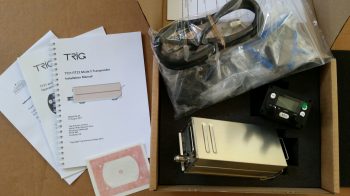
I started out today prepping for glassing up the last third of nose wheel cover on the aft side when my package arrived from Aircraft Spruce.  This was one of those special deliveries since it included the last of the major panel components that I’ll need to actually operate the aircraft through my 40-hour fly-off: the Trig TT22 Mode-S Transponder.  Now, I will be picking up a remote-mounted HXr-controlled backup radio as my COM2 and also a ACK E-04 ELT well before first flight, but clearly my to-buy list for avionics/instruments is down to just a couple items.

Opening the transponder box I could tell immediately that it was a high quality item with nice ring-bound manuals and a high-end accessory kit.  It amazes that besides TSO’d equipment, as homebuilders we often get high-end, high cost components that are packaged and equipped as if we had bought them second-hand off of Ebay!

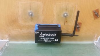
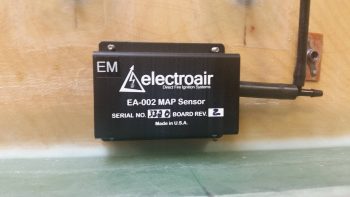
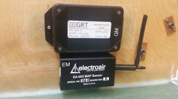
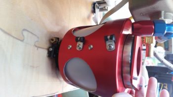
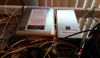
I grabbed the Trig TT22’s awaiting 2-digit electronics code label and affixed it to the top of the box, then placed the unit in it’s allotted location at the right side of the Triparagon’s top shelf, immediately adjacent to the HXr’s GADAHRS unit.  As a point of note, since I purchased this unit from ACS vs GRT it came with the panel mounted control head which I will NOT be using.  Moreover, I’ll need to incorporate a serial adapter from GRT that allows the HXr to control the transponder remotely and thus negates the need (and actually it can’t work with both) for the panel mounted control head.

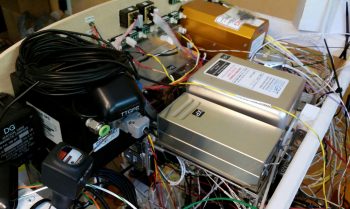
Here’s a shot of the two cohorts in crime atop the Triparagon’s cross shelf.  Note that neither one is actually mounted to the cross shelf yet.

After checking out the transponder and inventorying the rest of my ACS order, I then got back to the task at hand: finishing up insulating the nose wheel cover (NB).

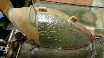
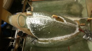
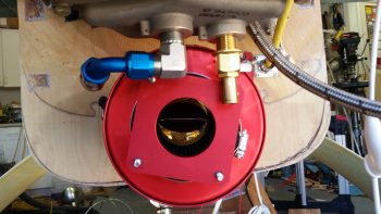
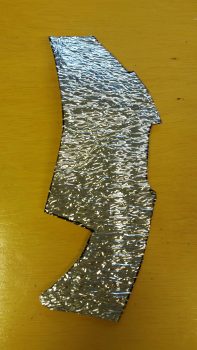
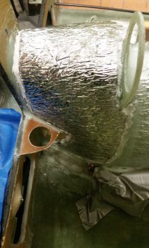
I started by dialing in the shape and cutting out the top aft “saddle piece” — that just happens to be a bit “New Jersey” shaped in my book– that will make up the first of the last 2 pieces of insulation that needs to go onto NB to finish up the actual insulation part.

I then RTV’d the top “saddle” piece of insulation into place on the aft side of NB.

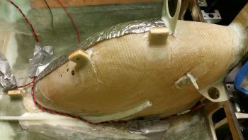
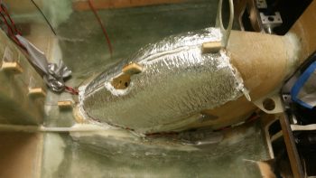
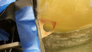
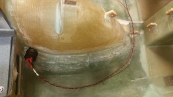
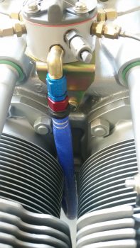
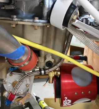
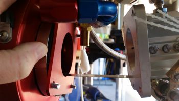
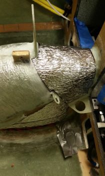
On the left side of the top “saddle” insulation piece it mates up with the front 2/3rds insulation and ends just above the cigarette lighter mounting bracket.  I then added 2 more pieces of insulation below that to fill in the triangular area on the left lower aft side of NB.

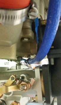
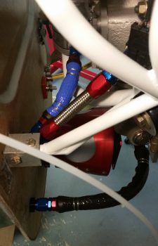
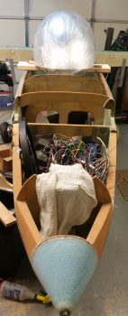
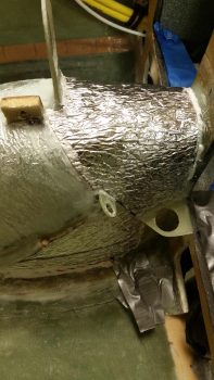
Since clearance is tight in the areas of both chargers, I left the very lower aft corners of NB bare.

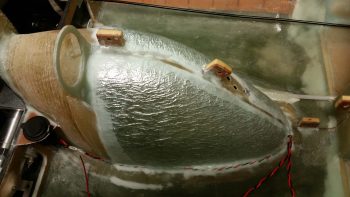
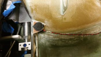
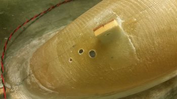
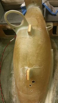
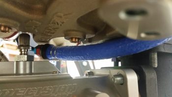
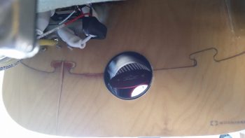
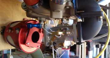
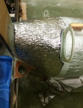
On the right the top “saddle” piece of insulation covers the last aft 1/3 of NB down to the fuselage floor.  It of course also mates up with the front 2/3rds NB insulation.

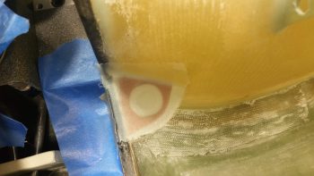
I then micro’d the edges of the new NB insulation pieces on right side . . .

and the left side.

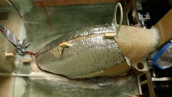
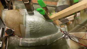
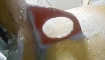
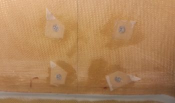
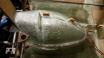
I then glassed up the last of the uncovered insulation on NB using 2 separate pieces of BID to create a 1-ply covering that overlaps right around the mounting tab for the parking brake on the left side (close to where the intersection of the “saddle” piece of insulation meets the bottom aft piece).

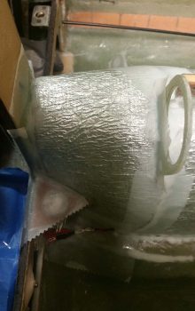
I then peel plied all the intersections, overlaps and edges of the layup.

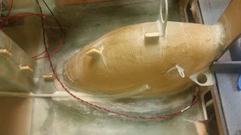
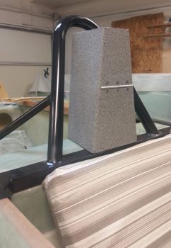
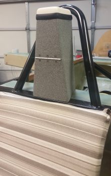
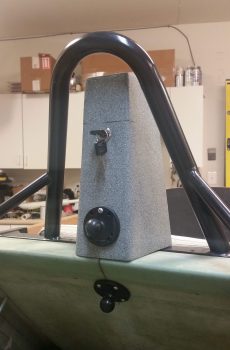
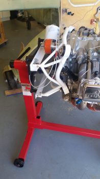
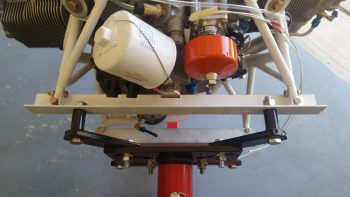
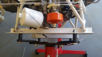
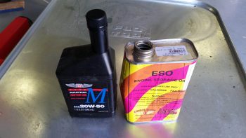
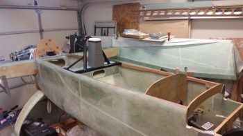
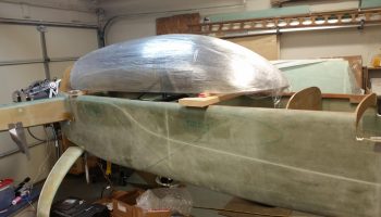
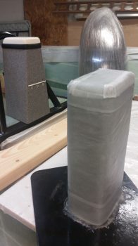
While the final NB insulation glass cured, I then spent a couple hours glassing the “Oil Tower” that I created by using a Phillips 66 aviation oil bottle wrapped in cardboard and taped up to create what will be a tall narrow oil box with a clamshell-type lid held securely in place with a hinge on the forward side and a Dsuz latch on the aft side.  Again, this puts the weight of a full quart bottle of spare oil (~1.7 lbs) as far forward as possible, and provides me a consistent out-of-the-way place to store my oil (read: no headrest or CS spar oil storage!).

Believe it or not, I actually used slow hardener on this layup since I knew it would be curing overnight and I had no need to use any of my precious fast hardener on this guy.

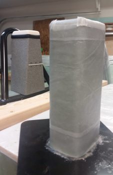
Although you can’t see it, the bottom of the Oil Tower is actually a piece of 3/8″ thick PVC foam, glassed on the top (interior) side that I reclaimed from the piece that I cut out of the left vertical armrest notch for the lower seatbelt bracket access.

I micro’d the edges of the foam base piece –which matches the outline of the sidewalls– and then extended the sidewall glass to overlap onto the foam base piece.  Once I open it up I’ll glass a ply or 2 internally to overlap from the sidewall onto the foam base (interior floor) for added strength.

Lastly, I left the bottom of the foam base bare so that I could more easily cut out and embed mounting hard points into the base before covering the very bottom with glass.

I then peel plied and left the “Oil Tower” to cure.

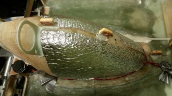
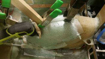
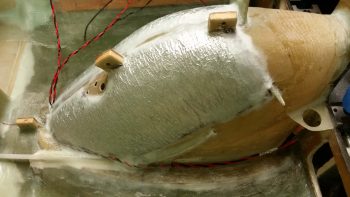
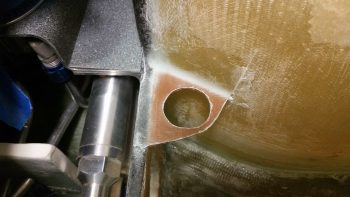
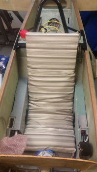
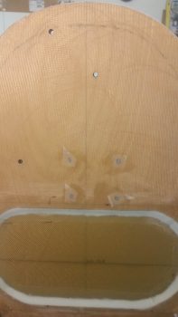
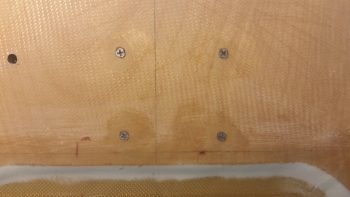
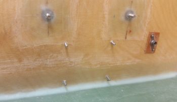
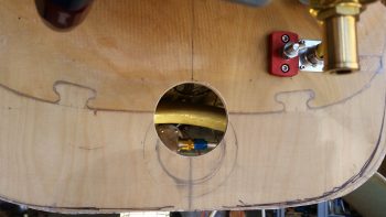
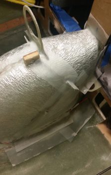
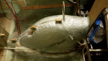
After taking a short break, when I returned to the shop my final NB insulation layup was pretty much completely cured.   I pulled all the peel ply and then did a rough clean up of the layup by clearing/cutting out all the holes I had covered up with the layup.  In fact, 2 mounting tabs: the right side USB charger mount and the parking brake handle mount both got an extra ply of glass added to them for strength (and ease of laying up the insulation covering BID).

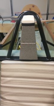
Here’s the final shot of my NOW insulated Nose Wheel Cover (NB)… which I of course quickly marked that off my to-do task list!

I will repeat and alas, reiterate, that completing these prerequisite tasks personally does not get me jazzed like seeing the big “real” pieces of the airframe go together, but in my attempt to stay disciplined by front loading these tasks and doing them while I still have true access to these areas that would be so much more difficult to reach in the future, I truly believe I’m optimizing my build sequence as best possible…. although it may not seem fun or sexy right now! (for any of us!)

Tomorrow I’ll continue with my “3 DAY BLITZ” to get more of this hard to reach install and configuration stuff out of the way before starting in on the actual nose and canopy build.


Chapter 13/22 – Keepin’ NB warm!

Or rather my legs actually…. !

Shortly after I got back from NC I tweaked my back a little, so yesterday, still a bit tired from the haul down to NC, I was taking it a little EZ and unintentionally ended up making the whole day a research day … I did some personal stuff and spent a lot of time on the computer researching build stuff, including a nascent plan for how I’m going to knock out the significant number of metal projects I have coming up for various parts of the build . . . throttle handle lever, starter contactor mount, canopy lever are the big ones off the top of my head.

Today I got busy on one of my tasks that I am charged to do under the auspices of the 3 DAY BLITZ, Round 2: insulating the Nose Wheel Cover (NB).  After thinking about it a bit I decided to insulate NB in 2 phases, the front 2/3rds section and then the remaining 1/3 aft section.  By doing it this way, it allows for more glass-to-glass contact and secures the insulating material better in place… IMHO.

I also split the 2 sides so to create a narrow trough down the center which would be a low-point depression in the insulation to ensure clearance for the bottom edge of the Triparagon when it’s mounted in place.  Again, it would also provide a glass-to-glass securing point down the centerline of the insulation.

After giving the NB and surrounding fuselage floor a thorough sanding, I started by cutting to shape and then using Silicone RTV to secure the insulation to the right front 2/3rds of NB.  Remember, I’m cheap . . . and if you want to be read in on a little secret: this insulation is the flooring material underlayment I bought in Germany to use as a hot-tent for post curing the fuselage back in 2012!  Ha!

You can see that although this insulation is somewhat thin, it still has an edge on it.

I then cut to shape and RTV’d the left front 2/3rds insulation in place on NB.  You can see I used the attached nylaflow –that runs partway up NB at an angle for the parking brake cable– as the demarc point for ending the first round of insulation, with the underside getting insulted in phase 2.

Here’s another shot of NB’s front 2/3rds area insulated and ready for a 1-ply BID glass covering.

I then whipped up some epoxy (with fast hardener) and micro’d the edges of the insulation and the intersecting corners of NB and the fuselage floor, where the respective pair of charger wires run along each side.

I then laid up one solid ply of BID across the entire front 2/3rds area of NB covering the insulating material I had just RTV’d in place a bit earlier.  To keep the glass in the narrow center trough between the 2 pieces of insulation in contact with NB for a good glass-to-glass bond, and as deep as possible for clearance with the Triparagon, I took a length of plastic tubing (that was used for the gear leg conduits) and pressed it down over the peel plied center trough.  To keep the plastic tubing in place I of course had to come up with some clamping contortions to do so.

I also peel plied the glass-to-glass bonded patch where the 3 holes are for the OAT probes. I then filled an ACS baggy with sand, taped it up and set in place on the glass-to-glass bonded patch to compress the glass down and ensure the best possible bonding.  I leaned the 90° drill on it to keep the mini sandbag in place and add as much reasonable weight as possible.

I then spent a number of hours on the phone with fellow Long-EZ builder Brian Ashton from Alaska, and after sharing our war stories and build progress, I then went downstairs to the shop and pulled the peel ply and cleaned up the layup.

I didn’t see any issues whatsoever with the layup and am extremely pleased with how the first phase of my NB insulating came out.  As for the respective set of charging wires, I’m typically NOT a fan of burying wires under glass or micro, but here the runs are so short that if I did have a problem I could use the Fein saw to dig them out.  I oversized the wires simply to avoid any potential problems and to handle any added heat (negligible IMO) by being encased for about a foot in a ply of glass and some micro, so I really don’t foresee any issues.

Tomorrow I plan on finishing up insulating the NB cover and then press on with other internal nose & avionics bay tasks that need completing before the top of the nose gets constructed.


Chapter 22 – USB charger Dude!

Today was a bit heavy on research and planning… which I grabbed breakfast down the street and did a fair bit of that there.

At the risk of sounding like I’m obsessively repeating myself, my attempt over the next few days is to knock out some of the smaller tasks that are just that: smaller tasks now, much more difficult tasks later.  It may seem like I’m nibbling around the edges of the pie vs just jumping in and scarfing down the good stuff in the center (it does quite often to me!!) but I think –again– knocking out the small, easy stuff while it’s small, easy and ACCESSIBLE is a much better way to go in the long run.

Case in point is the USB charger bracket that is the twin of the left side nose wheel cover cigarette lighter charger.  My front seat USB charger will be located at the intersection of the nose wheel cover (NB) and the lower instrument panel’s center strut, on the right side… about as close the gear viewing window as you can get.  As I see it, this is otherwise dead space so a good corner spot to stuff something into.  And back to my original point, I can’t imagine trying to construct this somewhat innocuous little bracket in place with the top nose panels constructed.

I spent well over 2 hours on this USB bracket today, starting off with a good 45 minutes of trial and error measuring, test fits, mockups and tweaking to get the final USB charger’s bracket –which is a tad bit bigger than the cigarette lighter charger’s bracket– cut and drilled to the right shape and dimensions.  As you can see, the USB charger bracket was cut out of my 1/16″ phenolic stock.

I then sanded down the 1/16″ USB charger bracket to prep its surfaces for glass.

I then 5 min glued it in its place at the aft corner intersection of NB and the lower instrument panel cross piece.

I then prepregged and laid up 2-plies of glass top (I used scrap glass, so 1 ply BID over 1 ply UNI) and 1 ply of BID on the bottom side.  I used small flocro fillets for the corners, heavier on the flox.  I then peel plied the top side layup.

I then went out to dinner with my buddy Rob for a couple of hours while the glass cured. When I returned I pulled the peel ply, knife trimmed the layup and then sanded the rough edges to clean it up.

Here’s a shot of the lower layup… this is the first I’ve had eyes on this bottom layup since I did it all by feel the when I laid it up initially.  I intentionally drove the fillet away from the spot where the mounting hole is closest to the NB side to allow room for the large plastic mounting nut that secures the USB charger in place.  Of course viewing this pic did identify one more spot that I needed to knife trim.

And Voila!  Here’s a test fit of the USB charger . . . fits like a champ!

I don’t have any pics this time around of the next 2 items, but I spent well over an hour taping up one of the plastic aviation oil bottles I saved to create an oil storage box that will secure a quart of oil in the nose.  With oil being a bit heavy I figure why store it in the spar or headrest when I can eek out a spot for it towards the very front of the plane.  Plus, with a storage box with a securing lid just big enough to slide a quart bottle of oil into, I can also stuff a rag in there for use as well.  This may be round 1 since it might not come out as nice as I had hoped…. we’ll see (literally since I’ll make sure I grab some pics tomorrow).

I also spent a good hour doing the initial clean up with a straight razor blade on the myriad of runs I had when I clear coated the NG30 cover.  I swear it looked like the first time I had spray painted ANYTHING and had zero understanding of the whole concept of spray painting something!! IIRC it was outside at night so my pushing to get it done then just caused a bit more work for me now!

So with the USB charger bracket mounted in place, I can now press forward with my plan to insulate the nose wheel cover and secure it in place with a ply of BID.  I’ll also continue with my 3-DAY BLITZ to work all things internal to the nose and avionics bay before closing up the nose.


Chapter 22/23 – Little Systems

I’m kicking off the nose and canopy build with another 3-DAY BLITZ which we’ll call Round Two.  Essentially over the next 3 days I’m going to clean up some low hanging fruit tasks from the engine and also prep the internals of the nose and avionics bay (forward of the instrument panel) as a prerequisite for putting a lid on the nose.  For those of you who follow my blog I’m sure clearly by now you realize I don’t like minimizing access to a given area that I will then later have to go back and do a fair amount of work in.  The stuff that goes in the airplane either has to have time spent on it going in now or later, and if I have access now it might as well get installed while it’s significantly easier to do so.  So I am!

I started off the day by receiving a delivered order I placed while in NC for a set of new MS20001-12 hinges for the canopy.  After the issues reported by both Dave Berenholtz and Mike Beasley on the smaller MS20001-6 hinges called for by the plans, I figured I would make the decision early to implement these and save myself some pain.  So while down in NC I spent some time scrounging around online to find a source of supply for just a couple feet of these quite expensive hinges.

I then got to work finalizing a comprehensive order I’ve been building at Aircraft Spruce for well over a week.  Included in this order is one of the last of the big ticket instruments I’ll need for this build: the Trig TT22 Mode-S Transponder.  However, before pulling the trigger on the order I needed to determine my CAMLOC/Skybolt requirements for the wheel spats, which I did by measuring the thickness of the wheel pants and bonnet at the mounting hole points.  I then ordered a representative number of those CAMLOC/Skybolt components to test out.  Once the correct sized studs, receptacles and associated hardware are confirmed/dialed in, I’ll order the remaining components.

Then, per my discussion with Nick Ugolini about a year ago, I also determined that to get 30% compression (actually 37.5%) on my 0.2″ thick canopy “B” seal I need to compress just over an 1/16″ of an inch and have a 1/8″ spacer to keep it from going more than that. Again, as per discussions with Dave Berenholtz and Mike Beasley, I’ll build this gap into the left canopy frame side rail that rests upon the longeron so that it’s in place prior to glassing the canopy frame.  The final practical result will be a 1/16″ plate affixed to the left longeron both at the forward end and the aft end, with a matching set affixed to the bottom of the left canopy rail to create the 1/8″ gap for the proper compression of the “B” seal [BTW, I think I finally found that “pleasing shape” that Burt is always telling us to strive for in the plans! . . . haha!]

Moving on…

As I was running around doing some errands today, I picked up a cheap 17″ x 43″ x 2″ thick outdoor chair pad to use in the final dialing-in of my rudder/brake pedals, my canopy height and panel/F28 height (for visibility).  The pad fits so well I think I’ll use it as a rough template for my seat pad when I get to that point (Chapter 26 – Upholstery).

I then started in on the process of adding a thin ply of insulation to the nose wheel cover (NB).  As I assessed adding insulation to NB, I decided I didn’t want to run the wires for both the 12V cigarette lighter charger (left aft side of NB) and the USB charger (right aft side of NB) in a circuitous manner.  Instead, I wanted them to go as straight from Point A to Point B as possible, which means running the separate set of wires under the lower edge of the NB insulating material at/in the intersecting corner of NB to the fuselage floor.

Since the cigarette lighter adapter also serves as my PC680 battery charging port, and is subsequently connected to the Battery Buss, I used 16 AWG to ensure a robust connection.  I terminated the charging port end with the PIDG Fast-ON terminals included with the charger, twisted the wires together to mitigate any electromagnetic noise, and then labeled the wire pair.

I then did pretty much the same thing on the USB charger side (right) only with 18 AWG wire.  I still have to mount the USB charger in the corner between the aft side of NB and the lower instrument panel, which I’ll knock out during this 3-DAY BLITZ.

I then whipped a small batch of epoxy with fast hardener and made up some wet flox. After I filed down the round countersunk heads of the Electroair screws into a triangular shape to give flat gripping edges, I then floxed them in from the aft side of the firewall into the D-Deck area for mounting the Electroair MAP sensor unit.

Here are the 4 stainless steel countersunk screws from the firewall side.

And here’s an even closer shot of the 4 stainless steel countersunk screws that will secure the Electroair MAP sensor in place.  As you can see I peel plied them to ensure the firewall surface remains even and smooth.

A few hours later after the flox had cured I pulled the peel ply from over each screw.

Here we have the 4 Electroair MAP sensor mounting screws floxed in place from the aft firewall side.

And the Electroair MAP Sensor set in place on its 4 mounting screws.

And here are the two MAP sensors that will be in use on this airplane: the top-mounted GRT MAP sensor and bottom-mounted Electroair Electronic Ignition MAP sensor.  As a point of note, the MAP line does actually run to the PMag in the engine compartment as well.

With the epoxy I mixed up to flox in the 4 Electroair MAP sensor mounting screws, I also whipped up some micro paste to secure a length of 1.75″ x 0.035″ wall 6061 tubing over the existing 1-1/4″ tube that exits off the left side oil heat air duct that heads towards my left foot.  This all will be located just forward of the lower left instrument panel and I needed this thicker diameter attach point for 1-3/4″ SCAT tubing that will feed the panel-mounted eyeball vent for heating a critical component of the aircraft: the pilot!

Here’s the top side of the tube addition to allow 1-3/4″ SCAT tubing to be attached to feed the panel mounted eyeball vent.

Here’s a mockup with the SCAT tubing to show what I’m talking about.  The 1-3/4″ scat tubing is vertical while the 1-1/4″ scat tubing (that heads to the left foot vent) is horizontal.

I then measured, assessed, determined and drilled the 3 holes required for the 3 separate OAT probes I have for the panel: 1 each for the HXr EFIS, 1 each for the Mini-X EFIS, and 1 each for the MGL Clock/OAT.  I emulated Marco in his placement of his OAT probes since on the forward side of NB the OAT probes remain internally clear of the nose wheel when it’s retracted.  I wanted the OAT probe mounting holes situated because I’ll use this location to provide a glass-to-glass bond to secure the NB insulation in place.

Today was the first day in a LONG time that has been warm enough for painting.  Since my pilot headrest was still taped up from the first round of painting this was definitely low hanging fruit. [You may remember the cans of spray paint, although labeled the same, were distinctly different colors so I dumped my 2-tone cabin paint scheme and am simply going with one color].  I painted a couple of coats of the gray granite on the head rest and then after about 4 hours I hit it with a couple of coats of matte clear coat.  A few hours later, when the clear coat had cured to the point to allow handling, I removed all the protective tape from the headrest.

I then attached the RAM air ball with a screw and put the keys back in the lock (mainly in an attempt to help keep track of all this stuff!).

I then set the GPS antenna “radome” back on top… just something for a little fun and to spark some conversation at fly-ins! (grin)

I wanted to also knock out the last couple of engine hoses that were available for fire sleeving… Again I sealed the bare fire sleeve ends with 3M fire barrier and then covered those sealed ends with narrow strips of black heat shrink.  Top black hose is the oil heat oil return line back into the sump while the bottom blue hose is the fuel pump to fuel injection servo feed line.

Tomorrow is roughly day 2 of my 3 DAY BLITZ on the nose components and I intend to be doing a fair amount of glasswork.


Chapter 23 – Engine Pickling… MC

“MC” for those of you never having filed a travel voucher for an Air Force mission was always the last 2-digit code annotated and stands for “Mission Complete” . . . which is currently the status of my engine pickling endeavor.

I will note that with the big task of welding up the engine stand mounting brackets and seeing my buddy Greg off over a couple of nights really put a dent in my schedule, and put me way behind the power curve time-wise.  Since I had a locked in rental on a moving trailer, and a locked in timeframe that I needed to be in NC, my back was somewhat against the wall.  Still, the primary goal here for me was to get this engine pickled, and then move what I could in the allotted time I had left.  I just was not going to risk any internal engine corrosion with any more time than was necessary.  In short, it was time to get this engine pickled.

With having removed the engine last night from the fuselage, I then did the limited trial and error dance for getting the bottom engine stand mounting bracket mounted to the engine mount.

However, the top mounting bracket was the big dance, and it took a couple of hours to dial that baby in.  The primary issue was that I forgot how the engine mount stubs –and thus the engine mount extrusions– are at a slight angle to follow the fuselage angle (this is denoted in the plans).

After much wailing & gnashing of teeth, a number of expletives and my new boneyard of broken drill bits (I think one side of the mount ended up so hot that it was in an annealed type state… since drilling a hole into it was like going through stainless steel) I finally got it all put together and then the engine mounted to the stand!

Here’s a better view of the engine mount attached to the engine stand mounting brackets.

And a couple of views from the top.

Ah, yes, and of course here we have a view more from the lower side.

I also drilled a hole through the lip of the oil drain valve to accept a 0.041″ piece of safety wire.  I then threaded the oil drain valve in place.  Unfortunately I was remiss in remembering that this was a Japanese made oil drain valve, and thus metric, so my 3/4″ wrench was just a hair loose on it.  When I really went to snug it up that last little bit I rounded a couple of the wrench flat corners over.  I then grabbed a 19mm wrench to finish up the last little bit of snugging it up tight.

I removed the spark plug cylinder dehydrators from the bottom side of each cylinder and replaced them with standard aircraft spark plugs.  I then removed the top spark plugs while I squirted preservation oil into each cylinder, and then replaced them with standard aircraft spark plugs as well.

I sprayed approximately 2 oz of PolyFiber Engine Storage Oil (ESO) into each cylinder when its piston was in the down (inboard) position.  I will admit that I realized as I was prepping for the pickling of the engine that an optimum solution would have been to have cover plates for both the intake and exhaust manifold ports, but I didn’t have either, and again, since I was in a time crunch I pressed forward and simply placed an oil drip pan underneath the engine for any runoff.

I will say that I shown a pen light into each cylinder with the top plug out, and what I saw on the each cylinder wall gave me a huge sense of relief.  I could see the honing of each cylinder wall with bright shiny metal and NO corrosion…. which I’m very thankful for.

I then poured 3 quarts of Phillips 66 20W-50 oil into the engine, fed in the remainder of the ESO and then poured in an unused quart of Harley-Davidson 20W-50 to top it off.

With my 4+ quarts of oil in the sump, I then flipped the engine upside down and let it sit that way for a good 5+ hours as I loaded up my rented moving trailer.  My goal here of course was to bath the top-mounted camshaft in a bunch of oil.

In my haste I failed to cap the oil heat return fitting so it spit out a bit of oil when I flipped the engine upside down.  Beyond that little issue the engine stand seemed to work exactly as I thought it would in allowing me to wrench on the engine and also rotate it as if it were on an “engine spit.”

Before I left for NC I turned the engine back right side up and attached the hook of the engine hoist to the top engine lifting tab.  I’ll turn the engine back upside down when I return from NC, but since I just welded up the engine stand mounting brackets I didn’t want to test my luck (just in case).

I did leave a bit of a gap between the engine hoist hook and the engine lift tab to allow me to quickly identify if any of the welds on the engine stand mounting brackets gave way while I was gone…. again, just a precaution with an expensive aircraft component.

For the final push on the engine pickling, as I was working on the engine I was also concurrently baking up another batch of pink desiccant.  Once it had turned blue and cooled, I then recharged all the cylinder dehydrators and the main engine dehydrator bin.  I then removed the top spark plugs and replaced them with the spark plug cylinder dehydrators.  Note that now the spark plugs are mounted on the bottom of each cylinder with the spark plug cylinder dehydrators on the top.

Again, I’ll be gone for a few days, and with the engine now off the fuselage and pickled for the time being, when I return I’ll be putting all my energies into building the nose and canopy to finish off the aircraft centerline build.


Chapter 23 – Engine Stand Brackets

I’ll start by apologizing again for my POS phone camera…. it annoys me that apparently the only thing it’s good for is selfies.  But it’s all I have right now, so please bear with me as I bear with posting these crappy pics (that I often take 2-4 shots of and all are still slightly out of focus…. and yes, I’ve checked the settings many times!)

I started with a 1″ x 1″ angled steel bar that I had on hand.  It had some surface rust but I was able to remove the majority of it.  I then marked 4 x 1.5″ tabs on one end, drilled holes that would allow for a welded “hardpoint” between the flat intersecting pieces of metal being welded together, and cut the 4 x 1.5″ mounting tabs from the angled steel extrusion.

I then set the mounting tabs on the associated 1.5″ x 1.5″ angled steel main engine stand bracket cross pieces –top & bottom– to ensure I had them set in the right places.

Now, as I mentioned during my TIG welding setup it’s been a couple of years since I’ve welded, but with both the high expense of Argon gas and my limited time I jumped right in. I knew there was Argon in the bottle, but it was low enough it wasn’t really registering well. In addition, the nifty little cheat sheet weld chart that Lincoln gives out during the EAA Tig Welding Workshop called for a 3/32″ Tungsten electrode for 1/8″ steel. I only had 1/16″ on hand.

Nonetheless, I trudged forward and laid down some appropriately crappy welds my first go at it.  Towards the end of it I could tell I was definitely out of Argon gas, so with about 45 min left before the Gas shop closed I threw my empty tank in the truck and went on my quest to collect a fresh UBER EXPENSIVE ($90!!!) tank of Argon. [As a point of note, I ground and re-welded any of my initial welds that looked lacking in the strength department… with my limited time available, ugly welds here were acceptable as long as they were strong!]

Upon returning back to the shop with a fresh full tank of Argon and some 3/32″ electrodes, this was what the other side welds looked like.  Just a tad better I’d say… (yes, still not up to par with the gorgeous TIG welds we see on YouTube, but again, strength was what I was after here, not necessarily beautiful welds!).

With the lower engine stand mounting bracket complete, I then started on the top bracket. Once I was finished with the top bracket, I spray painted both engine stand mounting brackets with the same fast drying white paint that I used on the engine mount.

While the paint dried on engine stand mounting brackets, I then welded the 0.035″ walled 1/2″ 4031 steel tube inside the 1/2″ NPT x -8 AN oil heat 90° fitting.  It took me a bit to rig it up so I had good access and a good welding angle, and I have to say I was going along beautifully for the first 75% of the circumference of the weld.  I had to reposition the setup and I had only one little bit to go on the final weld when I slightly dipped the electrode into the puddle. Well, with so little to go I trudged forward to finish it.  Mistake.

Within about 2 seconds of dipping the electrode into the puddle –with my trying to concentrate on the thicker fitting’s base metal (I tend to go high on internal corner welds)– I blew about a centimeter diameter hole in the thinner walled tubing.  Since I had to buy a foot of this stuff, I ended up simply cutting a patch out for the hole from the other end of the tube.  I then prepped the patch piece and the hole area, and tacked it into place.

I ran some water through the tube to see if the patch worked, but I have a couple of leaking spots that I’ll need to do some touchup spot welds after I return from NC.  For now this is good, and I cut the 4130 tube at my calculated 4.4″ long (high actually).

I then ran out for a final going away dinner for buddy Greg since in reality this is the last time I’ll see him in quite a while.

When I returned, the quick dry paint had cured.  I then determined the best bolt hole locations for my configuration and drilled out the 1/2″ holes that allowed me to bolt the respective engine stand mounting brackets to the beefy engine mounting arms.

Here’s a closer shot.

With the engine mount ready to go, I then unmounted the engine from the fuselage.  I took this pic because I would often bump the engine and the starter bolt that I had setting in this location would fall off onto the shop floor.  However, it stayed right in its spot the whole time I removed the engine from the fuselage, so the operation must have gone fairly smoothly . . . both literally and figuratively.

Since I needed to make a decent amount of noise and do some grinding and drilling on the engine stand mounting brackets to get them mounted to the engine mount, I called it a night.


Chapter 23 – Tailored Sleeves

I started off today prepping some of the metal that I’ll use in constructing the mounting brackets that I’ll mount the engine & engine mount to on the engine stand (say that 3 times fast).  That didn’t last very long before I had to pack all the compressor hoses back in the shop to go to a Dr’s appointment that took a good 3 hour chunk out of my day.

From there I grabbed lunch and headed to my local Village hardware store for some 1/2″ nuts & bolts for the engine mount stand brackets.  My best bud Greg from my Air Force days, who I rarely get to see, stopped by shortly after I got home for a few beers in the shop as I gave him the rundown on my build progress.  Greg got a new job down in the Norfolk area and will no longer be in this area as of Friday.  Since I’m leaving Thursday for North Carolina for a few days, I wanted to carve out some time to spend with Greg to send him off.

As you can see, the way my day unfolded I didn’t get much done on the build.

I did remove the prop and get it packed back up and put away . . . without incident.

I then decided to get something done on the build, and since it was too late to do all the grinding and metal cutting that I needed to do for the engine stand mounting brackets, I pulled off the -4 stainless steel braided fuel hose that runs from the fuel injection servo that’s mounted on the bottom of the engine to the fuel injection fuel distribution spider on the top of the engine.  I then took it upstairs and fire sleeved it.

As most of you are (painfully) aware, my phone camera is just not that good at capturing pics, and since I just couldn’t get both ends of the entire hose in focus….

. . . I took separate pics of each end of the hose.

I have to say that the first couple of hoses I fire sleeved I used up the stainless steel wire that came in the package with the ClampTite tool.  Little did I know at the time that they included 0.041″ stainless steel wire with the tool, because when I used 0.032″ wire on this hose . . .  wow, it understandably went from quite the struggle to a fairly EZ endeavor wiring up the fire sleeve on this hose.  Yes, the ClampTite tool is infinitely more enjoyable to work with when using smaller gage wire!

After sealing the bare hose end edges with gray 3M fire barrier Silicone RTV and covering that application with a strip of black heat shrink, I then reinstalled the hose on the engine. So here we have the freshly fire sleeved -4 hose connected to the fuel distribution spider atop the engine.

And here is the lower side of the fire sleeved -4 hose connected to the 90° outlet fitting on the top of the fuel injection servo.  Since I marred the Adel Clamp drilling its mounting hole out to 5/16″ diameter the last time, I’ll make up a fresh one it comes time to do the final install of the hose.

And one more shot of the newly fire sleeved fuel distribution outlet hose coming from the top of the fuel injection servo.

Tomorrow I’ll perform my welding tasks on the mounting brackets for the engine stand, get the engine off the fuselage and onto the stand, then appropriately pickle the engine.  After that I’ll roll solely into move mode to start packing up more of the house to get my stuff moved down to NC.


Chapter 21/23 – Wired . . .

I started out today with kind of a fun little project: assembling the engine stand that I picked up at Harbor Freight with a 20% off coupon.  As I was assembling it, a note in the instructions caught my eye: “Not for use with Aircraft” . . . hmmmm?

I also set the lengths of angled steel on the top and bottom mounts to provide an idea of how those will mount to both the engine stand and the engine mount (this angled steel was one of the pieces that Marco cut for me on his ginormous metal band cutting saw… which cut through this stuff like butter!).

I then did about 2 hours worth of spring cleaning in the shop to get it a little squared away for all the upcoming activity.

Next, although I didn’t get a pic, I mounted the right wheel pant.  I noted some trimming I’ll have to do on the wheel opening, but it’s seriously on the order of about a 1/16th of an inch.  That will get it in line with the opening dimensions spelled out by Gary Hertzler.  In addition, I took some measurements on the right wheel pant that I had already taken on the left.  The conclusion was that the wheel pants match perfectly from the gear leg forward to the front pant tip.  However, from the TE of the gear leg to the back tip of the wheel pant the right one is about 3/16″ farther aft, or maybe I should say 3/16″ longer.  No big deal and it was more of a curiosity thing than anything… I can tweak it a bit when I finish the wheel pants.

I then set my sights on mounting the 8″ prop extension to the flywheel and the engine prop flange.  It took about a half hour, a block of wood and a bunch of medium strength taps with a rubber mallet to get that sucker seated to within about 0.1″ of the flywheel. Then I very gently tightened all the bolts to get the prop extension to seat tightly against the flywheel.

Then, as per Sam’s (from Saber Manufacturing) directions, I torqued the 6 prop extension, prop flange and flywheel bolts to 50 ft-lbs each.

I then safety wired the bolts in pairs using 0.041″ stainless steel safety wire.

This is my first go at safety wiring, so if anybody out there sees anything disagreeable, please give me a shout.  I’m always open to constructive criticism.  Of course, I’ll have my EAA chapter bubbas look at the build as well.

Here’s the final shot of the installed prop extension.  Let me tell ya, the only time this thing is getting removed is when the alternator belt needs replaced! [Tomorrow I’ll test mount the prop and of course will take some pics… so I figured I would get the prop extension install out of the way today].

It was getting later in the evening, so I decided to relax and watch some TV while I played with my new toy: a ClampTite tool.  I removed and brought the fuel line and oil heat oil line with me upstairs.

Then, using the Clamptite tool (another first for me), I fire sleeved the 2 hoses.  Note that I’m using blue fire sleeve for fuel lines and black fire sleeve for oil.

As I’ve seen on Joe Caraggio’s site and others, there seems to be a requirement out there (or at least a good idea) to seal up the ends of the fire sleeve so the wool-type lining doesn’t soak up any stray oil, fuel, or what have you.  I had some of the expensive gray 3M fire barrier on hand so I decided to seal up the ends with that.

Here I’ve applied the 3M Fire Barrier to the ends of each fire sleeved hose….

However, I’m not a big fan of how the gritty, blotchy gray Hi-Temp RTV ends looked, so I cut a narrow piece of heat shrink and covered the RTV’d ends up…ahh, much better!

My final build act of the evening was to simply reinstall the hoses back onto the engine.  I definitely think the fire sleeving will work and I’m glad I went this route.

Tomorrow is picture day and my next door neighbor will be using his Uber awesome digital camera to get some nice aft end pics of my Long-EZ build.  Once that happens, my next goal will be to get the engine off the fuselage and onto the engine stand.  I’ll then drop all my engine focused shenanigans and will start on finishing up the nose and getting the canopy built.


Chapter 21/22/23 – Schooled . . .

Today was a day of lessons for the ‘ol Airdog here.  First off, my buddy Dave B. asked me a question on this website regarding the use of an ANL type fuse link for the SD-8 backup alternator, and if I did use one was it located aft or in the nose?  Wow, ok… probably a question I should have asked myself and a big oversight on my part.

As I see it (after Dave’s prompting) the logic flows like this: I just moved the ANL40 fuse link on the B-Lead aft because the antagonist in my view was the main 40A alternator.  I again based this off of Bob’s statement that the fuse should be closest to the offending power source.  Ok, now the SD-8 backup alternator is in the back as well, but its 30A fuse –as spelled out specifically in the Z-13/8 system architecture– must be located within 6″ of the master contactor (in the nose).  But why?  The key I discovered is identifying the potential antagonistic power source, which I had done incorrectly.

I posted this question on the AeroElectric Connection forum and almost immediately got a response: the alternators are not the main point of concern since if the wire leads from them are rated at the max current they can produce, then the wire will be safe.  However, the battery is a source of potentially hundreds of errant amps hitting the wire if it decides to go a little haywire.

Thus, I had picked the wrong villain, and as Sun Tsu says, “Know your enemy.”   I did not. This of course meant that my action to move the ANL40 fuse link aft was all for naught, and moreover, incorrect.  Lesson learned.  So, my latest diagram should be depicted as such:

And my new configuration for the ANL40 is nothing more than my previous CORRECT depiction, shown here.   Ahh, the circle of life…. ha!  I haven’t yet moved the ANL40 fuse link, but I will be leaving the mounting pad on the face of the firewall in the hell hole until I know for certain that nothing else needs to get mounted in there.

In a subsequent discussion Dave and I discussed alternators going haywire, and as a point of note I’ll state that alternators such as the ones B&C sells have built-in OverVoltage protection to guard against runaway alternator current causing damage.

Moving on.

I had a lengthy discussion this afternoon with Mike Beasley, who many of you may know from his awesome website.  (Admittedly, there’s not a lot of verbiage on his site, but for the fellow Long-EZ builder the pictures on his website are a treasure trove of information).

Lesson #2 of the day for me was Mike providing me with the finer points of how he constructed his canopy.  We spoke a bit on a few other topics such as throttle and mixture cables, but the near 2-hour long conversation focused primarily on the canopy and nose build.  I am very thankful for the time that fellow Canardians take to collaborate on such tasks as this, and it really does make the build so much more manageable (and enjoyable).

While I discussed the canopy and nose build with Mike, the FedEx guy delivered my last (hopefully) round of fittings that I ordered from Summit Racing.  Again, my first choice for connecting the hose coming down from the fuel distribution spider atop the engine to the -4 AN 90° fitting on top of the fuel injection servo was the 150° hose end fitting.  And as I mentioned before, my backup was a 90° hose end fitting if the 150° hose end didn’t work out.

Quite nicely, however, the 150° hose end fitting worked like a champ!

For this fuel line, I also employed and test fitted an Adel clamp secured by the front left corner bolt where the induction air intake elbows mate together.  I think this Adel clamp position will work nicely to secure the -4 hose going to the fuel distribution spider from the top-mounted fitting on the fuel injection servo.

Here’s a bit closer view of the -4 fuel line feed to the fuel distribution spider from the fuel injection servo.

I then took a while to figure out and dial in the position and angle of my oil sump oil heat feed line that exits out of the bottom of the oil sump via a 90° steel fitting (that I calculated a 4.4″ tall standpipe will get welded to) to a firewall pass-thru fitting.  I had some angled hose end fittings on hand, but decided that to keep a nice constant curve around the RAM air box that I’d use straight hose end fittings.

I then spent a couple of hours assessing and dialing-in the flow and Adel clamp attach point for the final piece of hosing to complete the fuel line from the fuel intakes in the main strake-located fuel tanks to the cylinder fuel injector nozzles: the -6 hose from the fuel pump to the fuel injection servo.

At the fuel pump side I actually entertained the idea of cutting part of the flat flange insert at the corner of the engine mount in order to have the fuel pump out hose end fitting face outboard of the engine mount tube.  But, laying below the engine looking straight up at it, I realized that more of the hose end fitting was showing on the inboard side than the outboard side, meaning that I could get a more down angle of the hose end fitting by leaving it inboard.  So, no drilling or cutting of the engine mount flange took place.

On the fuel injection servo side, I had planned on actually running the hose aft and looping it in from the aft side to arrive at the fuel injection inlet fitting at a 0-45° angle. But then after looking at and assessing the travel of the mixture lever on the fuel injection servo, I decided to simply bring the fuel line down from the top from a slight forward-to-aft angle.

So here it is: the final fuel line piece for this entire aircraft.  Yes, of course the fuel VENT lines will still need to be run, but this does it for the actual fuel lines.

Tomorrow I’ll prep for the removal of the engine since I have the lion’s share of data that I need from having the engine mounted.  Moreover, I’ll most likely clean up the shop and take some pics of engine mounted on the fuselage before removing it.


Chapter 23 – RAM’in Air

Today, after a fair amount more research, I got down to the shop and pulled the trigger on drilling the 3-1/8″ hole in my firewall for the nose flange of the RAM air canister to fit into. As you can see by the original marks on the firewall, my new location is significantly higher on the firewall than where I had planned to place it originally.

I then test-fitted the RAM air canister and as I’ve mentioned many previous times, it does just fit . . . barely.  But it fits!!

Here we have the RAM air canister peeking through the firewall from the Hell Hole side.

And even though the RAM air canister is tilted down a bit on the aft end –since I’m not holding it in place– you can see the position of the aft air exit hole and how a piece of tubing from the RAM air box to the fuel injection servo will be clear of any entanglements from above such as the oil drain valve and the oil heat feed fitting.

Since I moved the fuel injection servo forward to position the top 90° outlet fitting into a “V” groove on the bottom side of the Superior cold air induction plenum for clearance, that reduced the distance between the aft face of the RAM air canister to the front face of the fuel injection servo from 5.5″ down to only 3.7″.  Still enough to allow flexing between the firewall-mounted RAM air canister and the engine-mounted fuel injection servo.

Also note in the pic below that the tubing in-between the 2 units will need to curve upward at the aft end about 1/4″ due to the position and angle of the fuel injection servo.  I don’t see this as being an issue since I will be using flexible SCEET tubing.

Here’s a wider angle shot showing a close view of how the units will look in their final installed configuration.

I then spent a good 30 minutes dialing in the location of the firewall mounted MAP sensor/ fuel pressure sensor/oil pressure sensor manifold block.  I think I’ve pretty much got it’s mounting spot located, but need to check just a couple more things.

I then started reviewing my canopy install and build plans.  I set the 4130 steel rollover assembly in place as well as the headrest to prep for putting the canopy in place and assessing clearances [A couple notes: A) the headrest will get repainted since I had that issue with 2 different paint styles coming from cans with the same label, and B) the white thing on top is my GPS Antenna “radome”… in case you were wondering.)

I then grabbed my canopy out of the back room and set in place on two 2x boards. Although the angle is still a tad bit shallower than I’d prefer on the front of the canopy, I still like this canopy much better than my first one.

Here’s a canopy shot from the front that I was curious to see.

With that, tomorrow I’ll be finalizing my engine-related tasks in prep for pulling the engine off the fuselage and mounting it to its engine stand, and concurrently I’ll be prepping for the nose and canopy install/build.