Chapter 22 – Triparagon Shelf

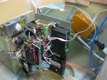
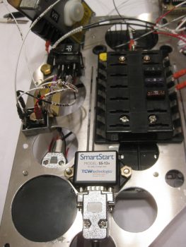
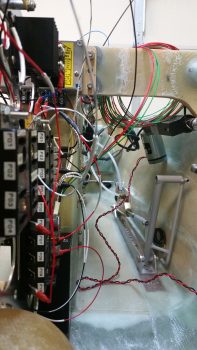
I didn’t go flying today due to high winds, so I started off with a little cleanup action on the nose gear wiring harness.  I’ve had a bundle of excess wires sitting on top of the NG30 cover for eons now and decided it was time to clear them off.  Also, instead of using butt connectors I opted for a more “elegant” solution and spliced the wires using a pigtail to secure the stripped ends of the individual wires together before soldering them.

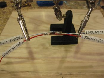
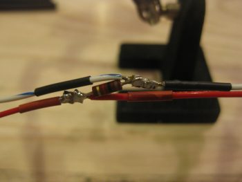
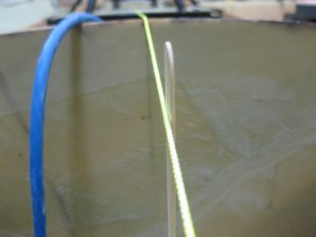
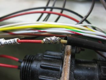
Here is the first set of 3 that I did this morning.  You can see the long 3-4 wire pigtail that I teased out of the stripped red wire on the left before cutting the rest of the stripped wires short in length to match the white wire on the right.

Splicing nose gear power wires

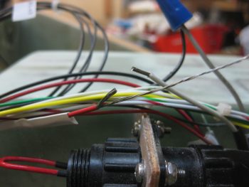
I then used the pigtail to secure the 2 wires together.  I could have used a wire or two less on the pigtail and also cut it a bit shorter, which added to the slight excess in the wrap. No worries though, it still worked great.

Splicing nose gear power wires

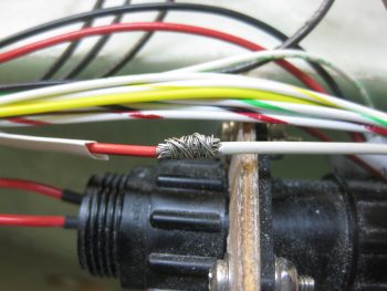
I then soldered the wires together.  I actually added just a tad bit more solder after I took the pic below.

Splicing nose gear power wires

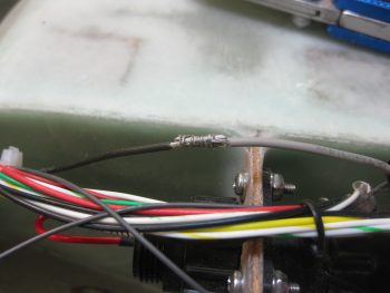
Here’s wire set #2 getting spliced . . .

Splicing nose gear power wires

. . .  then soldered.

Splicing nose gear power wires

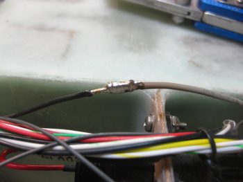
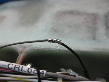
And wire set #3 completed in the same fashion.

Splicing nose gear power wires

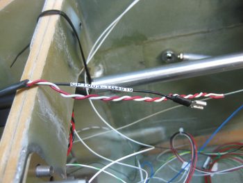
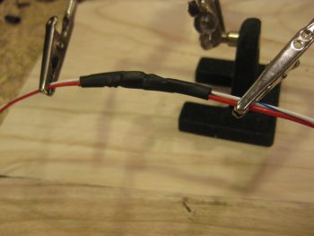
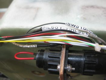
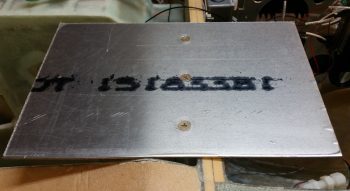
Here you can see all 3 wire sets spliced & soldered together.  I used shrink tubing over the joint for added joint strength, then simply used the label as a second layer over the shrink tubing for even more added strength.  After I finished with the shrink tubing & labels, I then hooked up up the battery leads and ran the nose gear up & down a bit to ensure the splices were carrying current, which they did.

Heat shrink labeled spliced nose gear power wires

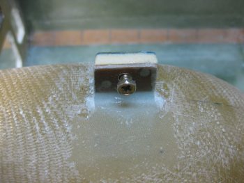
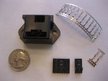
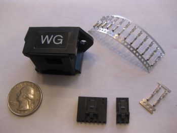
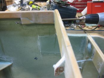
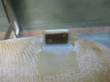
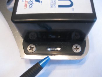
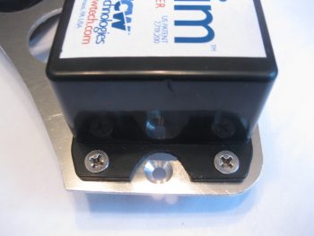
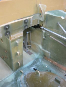
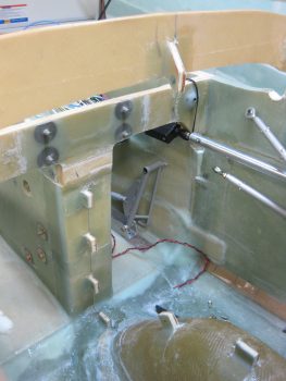
This morning at breakfast I drew up a plan for a bracket that would hold the AMP CPC connectors P3 (A/P pitch trim servo) and P5 (pilot stick grip) in place on the avionics bay sidewall.

I decided to go ahead and knock this out so that the glass would be laid up and curing overnight.  For the bracket material I figured I would use some leftover 1/16″ thick G10 that I had on hand.  I was going to use some of my 1/16″ brown phenolic at first, but it cuts a little easier than the G10 so I’m saving it to continue using for my nutplate backers.

G10 plate for AMP CPC connectors

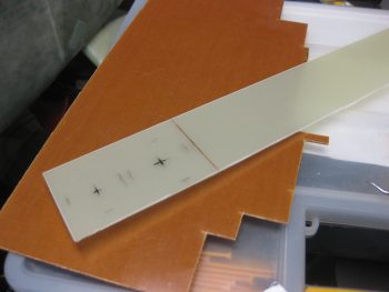
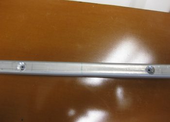
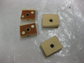
So I cut off a 3.5″ long piece off the 2.2″ wide strip of G10.  I then rounded the front corners.

G10 plate for AMP CPC connectors

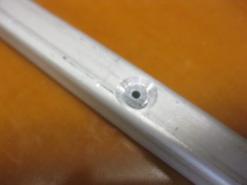
And drilled 2 pilot holes to mark the center of the larger holes.

G10 plate for AMP CPC connectors

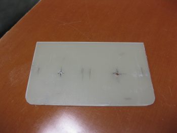
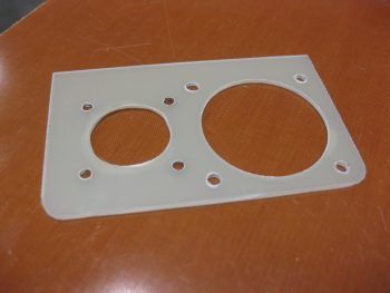
Which I then drilled next… along with the small #40 & #6 size screw holes, respectively of course!

G10 plate drilled for AMP CPC connectors

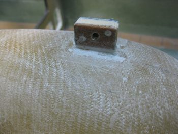
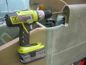
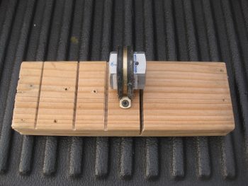
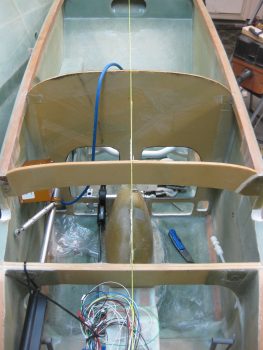
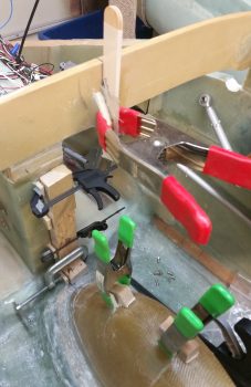
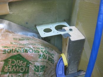
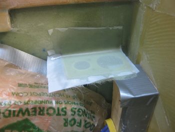
After finalizing my mounting location, I then 5-min glued the bracket into place on the sidewall.  I screwed the aft corner of the bracket to a clamped 2×4 piece to keep the bracket aligned while the 5-min glue cured.

G10 plate 5-min glued for AMP CPC connectors

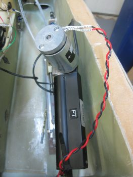
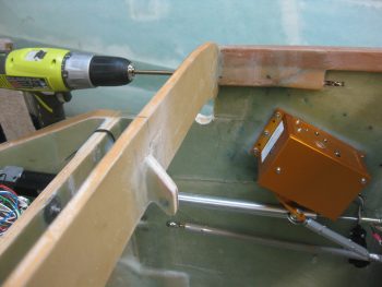
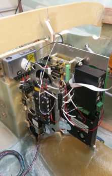
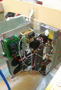
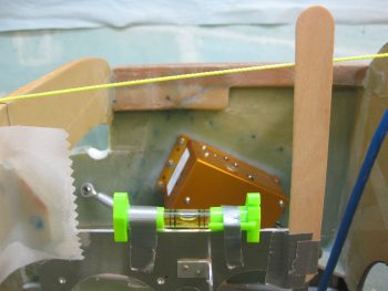
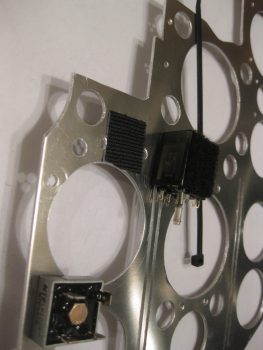
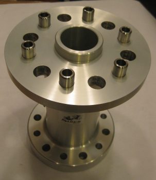
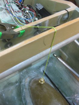
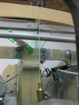
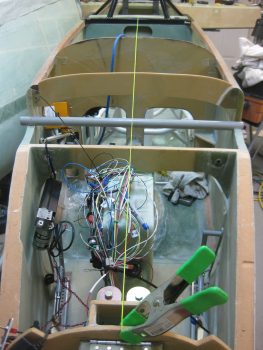
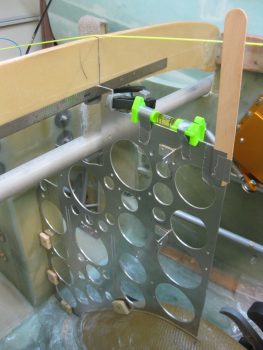
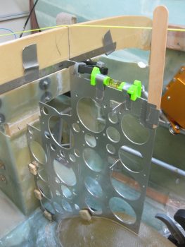
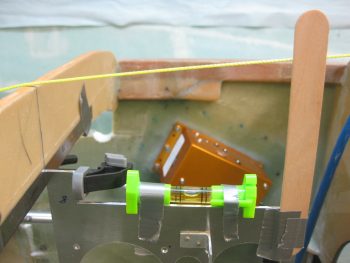
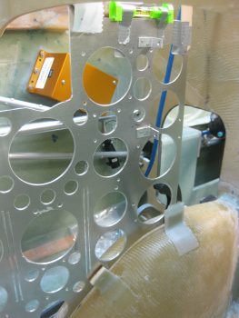
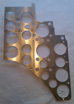
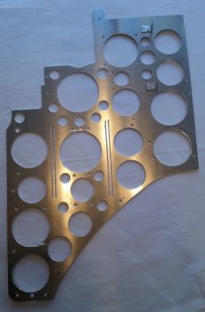
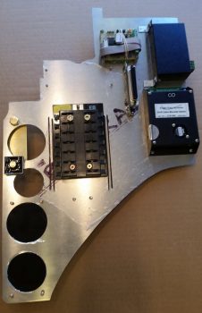
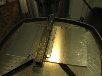
While the AMP CPC connector bracket 5-min glue cured, I got to work on the Triparagon cross shelf.  I marked out where the GRT GADAHRS will get mounted along with the centerline, then configured the angled mounting bracket locations.  I marked the mounting screw locations on the angled mounting brackets, then took the angled brackets and the cross shelf down to the shop to drill the holes.

Drilling Triparagon top shelf angle bracket

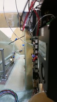
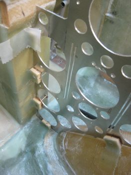
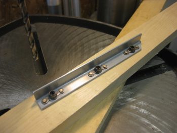
After I got the 3 mounting screw holes aligned & drilled, I then riveted nutplates to the left angle bracket.

Triparagon top shelf angle bracket nutplates installed

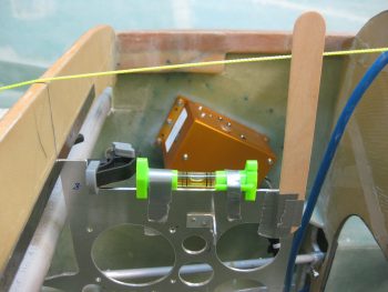
I then countersunk the 3 left side screw holes on the top of the Triparagon cross shelf and then screwed the shelf to the left side angle bracket.

Left side Triparagon top shelf angle bracket

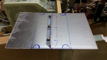
Here’s a top view of the 3 left side countersunk screws.

Left side Triparagon top shelf angle bracket

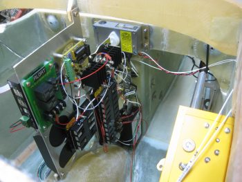
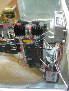
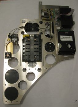
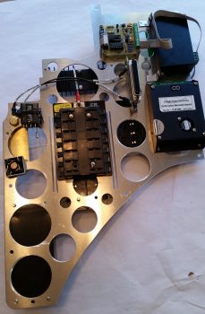
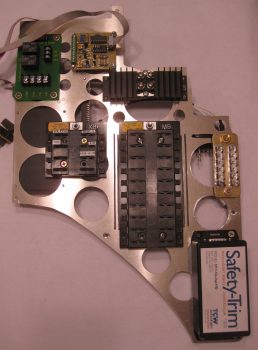
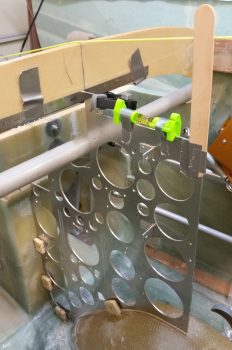
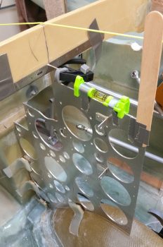
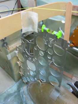
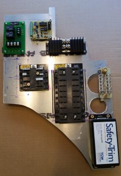
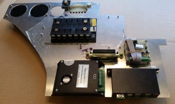
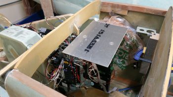
I then quickly mocked up the Triparagon cross shelf.  Again, I really am liking how the Triparagon is coming along.

Triparagon cross shelf

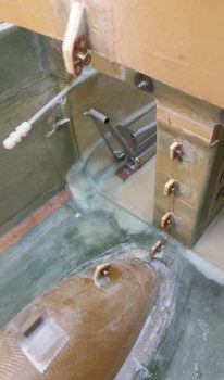
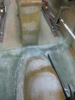
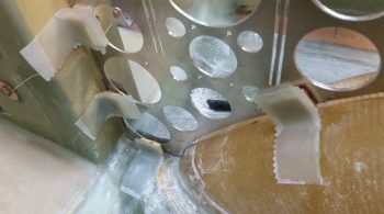
My last official act of the evening was to stop making noise and start making some fumes… epoxy fumes that is.  I whipped up some epoxy and laid up 2 plies of BID on the top side of the AMP CPC connector bracket.  I did use a flox fillet so the glass would transition well between the wall and the bracket. And of course I finished off the layup with some peel ply.

P3 and P4 AMP CPC connector bracket

If the winds stop acting up I’ll be flying tomorrow afternoon.  Still, tomorrow I will try to get the Triparagon cross shelf mounted, as well as the bottom/final glass laid up on the connector bracket.


Chapter 22 – Wires, wires, wires!

I started out today by trimming the reglassed aft lower Triparagon nutplate mounting tab with the Fein saw.  I then cleaned it up by sanding down the edges and then redrilled the hole to allow me to thread in the mounting bolt, which as you can see I’ve done below.

Lower aft Triparagon mounting tab

I then labeled the power wires coming off my Atkinson pitch trim servo motor with heat shrink labels on both ends of the wire.  As you can see I had to unravel the twisted wire then retwist them back together after the labels were on.  However, since the servo motor came from the supplier with these wires, I wanted to test them to see how they held up under heat & fire.  I snipped a test piece off and tried to burn it with a lighter for a good couple of minutes to no avail.  With my impromptu wire fire rating test complete, I then went ahead and affixed the labels and retwisted the wires.

Atkinson pitch trim servo power wires

With all my mounting tabs good at this point, I then brought the Triparagon down to the shop and officially mounted it!  Here’s a shot of the right side Triparagon.  Note the 2 white wires circling around to the right side of the pic and laying atop the Trio A/P pitch trim servo are the 2 Autotrim wires that interface with the servo.

Mounted Triparagon & Volt Reg - Right side

A shot of the right side Triparagon.  Again, after all the wires are in place I’ll do some major cable management on this rats nest before it flies.

Mounted Triparagon & Volt Reg - Right side

Here’s the left side Triparagon.  As I mentioned before, I’m extremely pleased with how this turned out.  My next task will be to configure & mount the top cross shelf that will primarily hold the GRT GADAHRS, Trig TT22 Transponder and M760REM COM2 Radio. Also attached to the upper level will be 3 airspeed switches, the Gear & Canopy Warning module, the piezo warning buzzer, and possibly some pitot/static manifold blocks.  All these components I just mentioned above make up virtually the entire electrical system other than those components that will be mounted on the Instrument panel.

Mounted Triparagon & Volt Reg - Left side

In the pic below of the left side Triparagon, you can see the Voltage Regulator in the upper left of the pic (again, mounted to F22, not Triparagon), the Endurance Buss (E-Bus/EB), TCW Smart Start module (SM), and the Autotrim components on the forward edge.  Note in the middle of the pic you can see the twisted red & black wires coming from the Atkinson pitch trim servo motor, terminated with small FastOn connectors to mount on the Autotrim relay (RP) tabs.

Mounted Triparagon & Volt Reg - Left side

Here is a close up view of the Trio A/P Autotrim components: a bridge rectifier (AT) and a DPDT relay (RP).  Again, these components interface with the TCW Safety Trim box, the Atkinson pitch trim servo, and the Trio A/P pitch servo for the autotrim feature to operate.

You may note some chicken scratching writing on the wire labels (…at least you do now!). When I added the Triparagon as a Component Wire Location Identifier [N=nose, I=Instrument Panel, H=Hellhole, etc.] I not only changed these wire labels from A (Avionics Bay) to T (Triparagon), but also the end component 2-letter designator on a few items, including both of these autotrim components.  Since this wire label heat shrink is not exactly inexpensive, I made the decision to choose function over form here in an attempt to be both cost effective & pragmatic.  Especially on wire labels that honestly are rarely going to see the light of day once this plane is flying.  To put this in perspective, I’ve already printed almost 100 wire labels and have attached about 2/3rd of those.

Autotrim components - Triparagon Left side

One thing I didn’t show in this post was the unraveling and sorting out of the rats nest of nose gear & AEX wires that sat atop the NG30 cover.   I had zip tied them up to keep them out of the way while figuring out my rudder/brake pedal placement, and it looked like an unsolvable/untraceable mass of wires.  In reality, since I had labeled so many of the wires, after a good 10 min I had it all pretty much figured out and the wires in place, close to their final runs.  So, for the nose gear & AEX power, ground & warning signal wires, I heat-shrinked a bunch of the second labels in place, cut the wires close to their final length and crimped connectors onto a number of them as you can see with the AEX ground wire below that will terminate into the Avionics ground buss (G5).

AEX GND wire terminated for Avionics GND BussI also went ahead and removed a good portion of the outer sheathing to the 3-wire cable coming from the Atkinson pitch trim servo positioning indicator.  The black wire of the group that I labeled and terminated with a FastOn connector will be grounded on the main panel ground buss (G4), while the red & white wires will tie together into one extension wire to feed an input into the GRT HXr to show trim positioning graphically on my EFIS.

Pitch Servo GND wire for Panel GND Buss

I’ll be flying tomorrow, which will of course wipe out a good portion of the build day. Regardless, I’m estimating another 2-3 days to finish up this crazy wiring & Triparagon stuff before I get back onto installing the wheel pants (yes, yes!  I know!  You’ll believe it when you see it… ha!)


Chapter 22 – Warning!

After spending a good bit of time in the AG6 warning annunciator manual last night, I started off today once again with about 1-1/2 hours of updating my initial electrical diagram for the dual AG6s I have installed.  I had originally only had the AG6s on this diagram with all other warning circuits listed in diagram 16, which specifically has a small housed module for the gear & canopy warning annunciation (shown below) along with the other warning stuff.

However, since I pulled all the individual warning LEDs off my panel and routed them all through my AG6s (the exact reason why I bought another one) it stands to reason that to show those circuits ALL warning circuits other than the gear & canopy warning module needed to be on the AG6 wiring diagram page while only the gear & canopy warning module wiring is depicted now on diagram 16.

I also realized after looking to copy a pic of the AG6 annunciator to show in this post that I may have never actually posted a pic of one.  These are stock pics below from the company who makes them, Aircraft Extras, Inc.

Here’s the entire system, with the boards mounted back-to-back on the upper Triparagon. Each board will have 6 warning circuits for a total of 12 and will display on a button that can be pushed in to acknowledge an alarm state.  Of course 2 AG6s means 2 display buttons on my panel.

AG6 Annunciator System

There are 3 available background colors for the AG6 display screens: red, green and yellow.  Below is a couple representative pics of the red & green displays.

AG6 Annunciator display buttonAG6 Annunciator display button

I also couldn’t find a shot of the JBWilco gear & canopy warning module that I’m using in my system.  I picked this up from a guy who built a bunch of them after he designed it for use in his Cozy.  He got tired of making & selling them, and I just happened to contact him right as he was selling his very last one.

J.B. Wilco Gear & Canopy warning module

As you can see, this module is very small and very light.  This will actually drive a pair of red & green LEDs on my panel.  These will be the only LED warning lights on my panel, since I’m wiring the Wilhelmson gear & landing brake LED pairs up to the AG6s to display gear up/down and landing brake up/down.  This module will sound a warning for the gear & the canopy, both visually through the LEDs and also through a warning buzzer.  BTW, this gear & canopy module will be the only warning that uses a buzzer.  I may configure other warnings to provide audio warning tones, but those will all be driven through the EFIS and only be heard via headphones.

J.B. Wilco Gear & Canopy warning module

Down in the shop I cleaned up the aft lower Triparagon mounting tab. I didn’t like the way the lower glass was attached on this tab from my original 2-ply BID layups on the right side of the nutplate mounting hard points, so I ripped off the glass and sanded it down to remove the stubborn stuff.

I also took the time to clean up the other tab layups, ensuring the edges were sanded down smooth.  I also drilled out the remaining holes in the glass for the mounting bolts.  All this sanding, trimming and drilling made a bit of a mess….

Aft lower Triparagon mounting tab

So before I vacuumed it all up, I decided I would make just a bit more of a mess by using my long 1/4″ drill bit to expand the #10 holes in the longeron doublers + the new extensions.  The 1/4″ hole is for the 4130 sleeves that will provide a solid channel for the long AN3-62A bolts that I will employ on the top canard alignment tabs vs. the plans alignment pins.  This is a mod I had seen in passing before, but I really took note of it after checking out what my buddy Dave Berenholtz was doing on his upper canard alignment tabs.

I drilled the left side first.

Exapanding longeron doubler holes to 1/4"

Exapanding longeron doubler holes to 1/4"

And then the right . . .

Exapanding longeron doubler holes to 1/4"

After my short 5-min drilling task detour, I then vacuumed up the mess I had made in the avionics bay area.  I then grabbed a small piece of plastic and prepregged 2 plies of BID and laid up the aft lower Triparagon mounting tab.  As you can see, and not surprisingly, I then peel plied the layup.  What you don’t see is that I then lightly clamped the same block of tape-covered wood that I used before to compress the glass a bit.  Finally, I used the leftover epoxy to seal the exposed bare foam on the 3 edges of each Triparagon nutplate mounting point.

Triparagon mounting tabs

With the lower mounting tab BID curing, I then took the Triparagon upstairs to finalize the on-board wiring cross-connects.  I started by printing out a number of wire labels on the white shrink tubing.  I then terminated two 22AWG red wires into one FastOn tab, one leg each to power the respective AG6s.  This FastOn connector will be mounted above the 2 shown on the left side of the E-Bus in the very left of the pic below (using the installed 1A fuse).

I then spent well over an hour finalizing the wiring for the Trio autopilot’s Autotrim feature. For the autotrim to work it must interface correctly with the TCW Safety Trim box.  While I was over in Qatar I worked with the respective gurus, Chuck at Trio & Bob at TCW, to finalize the circuitry for the autotrim.  With both of the gurus in coordinated agreement on the wiring scheme 2 years ago, I am just now finally able to implement it.  If you look along the upper left edge in the pic below (which is the actual upper forward edge of Triparagon), starting from the bottom you’ll note the DB15 connector housing from the Safety Trim box mounted on the other side of the Triparagon, then a Bridge Rectifier, then a relay marked “RP”.  These components make up the Triparagon side of the Autotrim system.  Once these interfaces are combined with 2 wires coming from the AP pitch servo and 2 wires coming from the Atkinson pitch trim servo motor, then Voila! … the Trio AP autotrim feature is wired for operations!

Trio A/P Autotrim & TCW Safety Trim interconnects

Being the social butterfly that I am, I then took the rest of the night off and went to dinner & a movie.  When I returned, I pulled the peel ply and checked the 2-ply BID layup on the aft Triparagon mounting tab.  Looks good!

Reglassed aft Triparagon mount tab 2-ply BID

Tomorrow I’ll clean up the overhanging glass and excess flox with my Fein saw.  I’ll of course redrill the bolt access hole, at which point I should be finished with my Triparagon nutplate mounting hard point installation.


Chapter 22 – Electrical System

Of course at this point my electrical system is analogous with the Triparagon.  Since, that being said, it is true too that the majority of my electrical components are mounted, or will be mounted, on the Triparagon.

After spending a good couple of days here & there populating the Triparagon components with wires to & fro the various parts, and finalizing a large number of circuits for the resident things on the Triparagon, it then stood to reason –and begged the question: Does it work?  Yes, it was truly time to test install this monstrosity.

So I did a mock up install of the wired-up Triparagon onto its mounting tabs in what I call the Avionics Bay (instrument panel to F22) of the Long-EZ.  I also installed the Voltage Regulator to see how it fit into the mix.  Below you can see the left side of the Triparagon & the Voltage Regulator.

Triparagon mock install

And a shot of it from the right.  I’d like to point out that up to this point the Triparagon has definitely met, or exceeded, my design goals.

Triparagon mock install

To give you all a sense of space…. specifically the space NOT taken up by the Triparagon (aka “legroom”) I took a couple of shots from close to straight in line with the edge of the the NG30 plates that house the nose gear motor.  In addition, the nose wheel cover (NB) also provides a “natural” barrier & offers a bit of standoff protection from wayward feet or legs to help keep the Triparagon out of accidental harm’s way.  I would like to point out that the current Triparagon wiring is in the initial “free form” stage and has not been organized, nor secured in place yet.

Triparagon mock installTriparagon mock install

There’s still just a bit of cross-connect wiring that needs to be done on the Triparagon proper, along with some final prep of the mounting tabs and the installation of the top cross shelf before I move back onto installing the wheel pants.


Chapter 22 – Triparagon, et al . . .

I started out today by undertaking the task of removing part of the TCW Safety Trim box’s lower mounting bracket, which was covering and in the way of the bottom Triparagon mounting screw hole.

Safety Trim Mounting Flange

So I removed a half moon notch of the mounting bracket and uncovered the bottom Triparagon mounting screw hole.

Safety Trim Mounting Flange Trimmed

In other news, I fried my heat gun last night.  So after a trip to Harbor Freight to pick up a nice cheap replacement heat gun, the weather was nice so I got to work outside to complete quite a number of cuts that were required with aluminum pieces & stock.

The first task was something that I’ve needed to do for a while now.  Since I finally got the correct sized Adel clamp in my latest ACS order, I was able to clamp down the Matco wheel axle nuts (from VANs Aircraft) that are used to mount the outboard sides of the wheel pants.  Since I won’t be using them as per their original design, I need to shorten them to 1″ in width from outboard to inboard.  Specifically, I won’t be using the cotter pin holes, so those are going away.

Just as I did my LWA9s & CNLs, I clamped the axle nut extensions into the Adel clamp & secured it with a screw.  I then took my time to ensure that the axle nut was 90° to the mounting board.

Outboard wheel pant axle nut

I then used my saw to slowly cut the axle nut down to 1″ width.

Outboard wheel pant axle nut trimmed to 1"Outboard wheel pant axle nut trimmed to 1"

The actual width came out to be more like 1.05″, which works fine.

Outboard wheel pant axle nut trimmed to 1"

Here’s a shot showing both axle nut extensions cut to 1″ in width.

Outboard wheel pant axle nuts trimmed to 1"

And a closer view . . .

Outboard wheel pant axle nuts trimmed to 1"

I then spent a good bit of time cutting the angled aluminum extrusions for the Triparagon upper cross shelf.  The 2 extrusions in the foreground of the pic below are for actually attaching the Triparagon’s top horizontal cross shelf to the vertical plate.  The larger angled pieces shown left-to-right are primarily additions to the front of the cross shelf that will be used for both mounting smaller components, such as airspeed switches and the warning horn, and also for the diagonal supports for the Triparagon top cross shelf.

Axle and Triparagon Aluminum parts cut

Since I was in a cutting mood, I also cut the 4130 steel tubes to length that will be used as bolt inserts in the longeron doublers for mounting the 2 newly acquired AN3-62A bolts. These assemblies will hold the canard in place at the upper mounting tabs in lieu of the plan style pins.  The bolts look a bit curved due to the camera angle, but they are in fact straight!

4130 Longeron Doubler bolt inserts cut

As I mentioned in the Project Update, I’m working on the Triparagon right now and my main goal in finishing it at this point of the build is really threefold:

  1. Ensure the Triparagon concept works & can be incorporated with a minimal (and acceptable) weight penalty.
  2. Install the Triparagon and ensure it fits while I have access to the nose area.
  3. Wire all the resident components on the Triparagon.  This is primarily wiring cross-connects for ONLY those circuits on the Triparagon. All other components will get wired as they are installed.

I should state that part of my fit & finish testing for the Triparagon includes the B&C Voltage Regulator, which is not actually mounted on the Triparagon, but immediately forward of it on the aft upper side of F22.  So I also wired all the connections from the Voltage Regulator to Triparagon components.

The long pole in the tent for the Voltage Regulator wiring was the wires coming off of pins 3 & 5, since they both connect to main buss power and pin 5 drives the warning signal to the AG6 warning annunciator.  The warning circuit required a 1K ohm resistor which I soldered into place.

Voltage Reg sensing and annunciator wires

Here you can see the 1K ohm resistor soldered into place, and the heat shrink in place on the respective wires to help build wire thickness for physical joint strength when the final piece of heat shrink is put in place.

Volt reg resistor for AG6 warning annunciator

The final heat shrink tubing in place over the resistor that’s tied in between the voltage regulator’s pin 3 & 5 wires.

Voltage Reg wires heat shrinked

Tomorrow I’ll continue to finalize the Triparagon components’ wiring cross-connects before moving onto the wheel pants install.


Chapter 22 – Inching forward . . .

I started off today by taking a pic of the pitch level of the mounted Triparagon.  As you can see, the addition of the last 3 nutplate mounting hard points tilted the Triparagon ever so slightly forward.  Nothing that can’t be reworked or overcome during the installation of the top “shelf,” but it is something for me to take note of to ensure I get 0° level.

Mounted Triparagon Pitch Level

Here’s a shot from the top to show the mounted Triparagon in comparison to the CL.  Again, you can see that the Triparagon is very closely aligned, so not bad.

Mounted Triparagon CL alignment

I cleaned up the left side layups on the Triparagon nutplate mounting tabs.  In the pic below you can see that the top F28 Triparagon mounting tab still needs to be cleaned up.

Trimming left side of Triparagon mounting tabs

I then laid up 2-ply BID layups on the RIGHT side of the Triparagon nutplate mounting tabs.  I then clamped these right side layups so that the glass would cure as flat & tight as possible to allow the Triparagon to mount back into place close to its original installed position.

Glassing right side Triparagon mounting tabs

While the right side Triparagon mounting tabs’ glass cured, I took a few minutes to re-drill the GIB seatbelt crosspiece screw holes, since I had inserted G10 hard points to buttress the square cross tube.

Re-drilling holes in G10 reinforcements

Here’s a closeup shot of the initial drilling of the G10 hard point in the GIB seatbelt crosspiece screw hole.

Re-drilling holes in G10 reinforcements

I then started back working on the actual Triparagon by remounting the electrical components to it.  I also drilled a couple holes to allow a zip tie to be used for mounting the Trio autopilot Autotrim relay –along with a patch of velcro.

Mounting Trio A/P Autotrim system relay

I wired up the G5 avionics ground buss to connect it to the bolt mounting the G4 panel ground buss.  Here’s a shot of the left side Triparagon.

Left side Triparagon

Another shot of the left side Triparagon.  You can see below that I also wired the E-bus to the Schottky diode.

Left side Triparagon

Below is a shot of the electrical components remounted to the right side Triparagon (with a pic hue for some reason).

Right side Triparagon

And another shot of the right side Triparagon.  Again, note that I wired the E-Bus feed by adding a wire between the Main Buss terminal to the Schottky diode (sorry for the slightly blurry pic).

Right side Triparagon

A few hours later I removed the clamped blocks off the Triparagon nutplate mounting points and cleaned up the 2-ply BID layups.

Glassed Triparagon mounting tabs

I also wanted to add a shot of my prop extension back from Sam at Saber Manufacturing.  As you can see, he added in 3/8″ bolt holes and bushings for the Silver Bullet prop on the prop side, and he also added 7/16″ bolt holes in between the 1/2″ holes for mounting the extension to the engine prop flange.

Modified prop extension

From here on out my main focus will be on wheel pants until I get those nearly fully installed.


Chapter 22 – Triparagon Mounting

I started out today by finalizing an Aircraft Spruce order that I’ve literally been compiling for over a month now.  I then entered all the ordered items into my tracking spreadsheet.

I then spent a half hour tweaking my main electrical system diagram & grounding matrix list, and then printed them out.

Down in the shop, I started out by bonding the Triparagon phenolic nutplate assemblies to their foam backers.  By the way, I used the tough H250 foam for the backers to add some oomph to these Triparagon mounting hard points.

I used 5-min glue to bond the nutplate assemblies to the foam.

Foam & nutplate assemblies 5-min glued

Here are 4 of the 7 mounting hard points bonded together with 5-min glue.  You may recall that I actually assembled these about a year ago.  I have one more rectangular nutplate assembly that I hadn’t fully put together before, so that needs finished.  I have another one in this bag that is an odd shaped nutplate assembly for mounting the very top of the Triparagon to the aft side of the F28 bulkhead.

Foam & nutplate assemblies 5-min glued

I then verified that the fuselage was level to allow me to match the top “shelf” of the Triparagon at 0° level for the eventual mounting of the GRT GADAHRS.

Checking fuselage is at 0 degrees

My next task was to mark the fuselage CL on the nose wheel cover (NB).  To do this I dropped a plumb line using my CL marks on the F22 & F28 bulkheads.

Finding center mark on nose wheel well NB

Here’s another shot of the plumb line for marking the CL.

Finding center mark on nose wheel well NB

After marking the CL on the nose wheel cover (NB), I then ran my plumb line down the CL of the fuselage to allow me to install the Triparagon as close to on-CL as possible.  At a minimum, I wanted the Triparagon mounted parallel to the CL, even if off center say 0.1″ or so.
Marking aircraft center line

I taped a level in place on the top “shelf” of the Triparagon.  I also taped a mixing stick to the top portion of the Triparagon to allow me to monitor its alignment to the CL string that I strung in place.  I then mocked up the Triparagon with the 4 nutplate assemblies screwed into place.

Mocking up Triparagon install

I clamped the Triparagon top mounting tab to the aft side of F28.  It took some trial & error to dial in the correct spacer thickness between the Triparagon top mounting tab & aft face of the F28.  It turned out my decimal fraction ruler was the thickness that did the trick to get the top shelf level with the longerons.

Checking level on top Triparagon "shelf"

Below is a shot of my mixing stick aligned to the CL string.  I intentionally taped the mixing stick on one side of the Triparagon plate so that the actual plate would sit very closely / directly under the CL string.

Aligning Triparagon plate with A/C CL

I marked the areas where the Triparagon nutplate mounts will get secured to the aircraft, removed the Triparagon and then sanded those mounting spots in prep for glassing the nutplate mounts in place.

CL marked & mount point areas sanded

Then, using 5-min glue on the nutplate assemblies, I glued the Triparagon into place.  I re-clamped the top mounting tab to the aft side of F28 while monitoring the Triparagon’s alignment.

Triparagon nutplate assemblies 5-min glued in place

I then set a 1″ dia. aluminum tube representing the elevator control spool tube –that will traverse from one side of the fuselage to the other– to ensure clearance between the spool tube and the Triparagon.

Triparagon nutplates 5-min glued

I then assembled my last rectangular nutplate assembly (the one that came with some assembly required!) and then made up an entire new nutplate assembly along with its foam backer.

I then cleaned up the 5-min glue on each of the 4 installed nutplate assemblies.  I then glassed these 4 nutplate assemblies in place with 3 plies of BID at each nutplate mounting hard point.

Triparagon nutplates glassed

Here’s a closer shot of the Triparagon nutplate mounting hard points glassed in place with 3 plies of BID.  I then of course peel plied each layup.

Triparagon nutplates glassed

After a couple of hours since the entire mounting process started, and with each of the 4 nutplate mounting hard points glassed in place, I double-checked the Triparagon’s alignment… which looked spot on.

Verifying Triparagon top shelf level

As the 4 installed nutplate mounting hard points’ 3-ply BID layups cured, I dialed in the placement of the remaining 3 nutplate mounting hard points.  I marked the Triparagon where the bolt (vs screws on the other 4 mount points) holes would go, then removed the Triparagon and drilled the 3 new AN3 mounting holes: one at the very top adjacent to the aft side of F28, another at the very aft bottom side of the Triparagon attaching to the nose wheel cover (NB), and finally one at the forward top edge of the Triparagon where it mates to the aft side of the F22 center strut.

I then reattached the Triparagon with the 3 new nutplate mounting hard points bolted in place, with 5-min glue slathered on the mating side of each of the nutplate foam.

Once the 5-min glue cured, I cleaned up the freshly installed nutplate mounting hard points, then added flox fillets (as I had on the first 4) and laid up 3 plies of BID on each nutplate assembly.

Below is a couple different shots of this.  Also note that I had just previously pulled the peel ply and cleaned up the 3-ply BID layups on the first 4 nutplate mounting hard points that I installed.

Round 2 nutplates installed & glassed

Round 2 nutplates installed & glassed

And here’s a shot looking aft.

Round 2 nutplates installed & glassed

I know I underestimated my Triparagon build & install timeline, but tomorrow I should actually get the Triparagon vertical plate install finished.  I’ll let these last 3 layups cure overnight, then clean them up tomorrow.  I’ll then glass in 2-ply BID layups on the right side of these 7 Triparagon nutplate mounting hard points.  I’ll then be finished with the lion’s share of the Triparagon installation, at least where the actual fuselage side is concerned.  The remaining mounting actions are getting the Triparagon top “shelf” plate installed with its requisite angled aluminum supports/anchors, which only deals with the actual Triparagon components.


Chapter 22/23 – Triparagon Cleanup

I started off today with a phone call from Sam Tilleman at Saber Manufacturing to discuss the modifications to my prop extension.  Since I found out from my engine builder, Tom Schweitz, that my engine mount bolts are 7/16″ vs the original 1/2″ bolts that they were identified as, I worked out the plan with Sam for him to drill those out as well.  Although a bit more money to have Sam modify the prop extension, again this actually worked out serendipitously in that having 3/8″ bolt holes drilled in between the 1/2″ bolt holes on the prop side of the extension, and 7/16″ bolt holes drilled in between the 1/2″ holes on the engine flange side, simply gives me a prop extension with 1/2″ lightening holes machined on each end.  Talking to Sam, this is pretty much the same configuration that Klaus Savier has on his airplane…. definitely not a bad model to emulate!

After getting the prop extension configuration settled with Sam, I then spent a few hours cleaning up the lightening holes by hand.  I also figured out where my #12 mounting holes for the Triparagon screws will be placed.  After figuring out the mounting screw locations I drilled the mounting holes and then countersunk the screw holes.

Cleaned up R side Triparagon

Here you can see the left side of the Triparagon with the cleaned up lightening holes.

Cleaned up L side Triparagon

You may have noted that there are a some visible gouges on the edge of a couple of the lightening holes.  This is directly attributable to the new style cordless drill batteries in that they twice the batteries seemed to have died while I was drilling and as I was removing the hole saw bit from the lightening holes, the drill surged again causing these edge gouging.  Obviously I’m not happy about these unsightly marks, but it doesn’t change the functionality of the Triparagon, it just slightly diminishes its appearance and thus knocks down my cool points tally a bit!

After cleaning up the Triparagon lightening holes I then worked for about 3 hours on redesigning my electrical system by removing the relay that controlled the circuit between the battery buss and E-buss as per the recommendation of Bob Nuckolls.  Technically, I repurposed that relay to be used as the heated pitot tube control relay with a net result of one less relay in the system.  I then updated the main electrical system diagram & the grounding buss matrix list.


Chapter 22 – Making Swiss Cheese

I started off today by mounting the main panel ground buss (G4), or “Forrest of Tabs” if you will, on the right side of the Triparagon.

Triparagon - Right side

On the left side I mounted the avionics ground buss (G5), and the bridge rectifier used for the Trio auto trim system.

Triparagon - Left side

Here’s a closer view of the components on the upper aft side of the Triparagon.

Triparagon - Left side

After mounting all the electrical components to dial in their configuration & spacing, I then pulled off all the components to commence drilling the lightening holes.  Which I did, spending the next couple of hours drilling the lightening holes.

Triparagon - Swiss cheesed

I’ll note again that after I initially cut out the Triparagon vertical from a panel of 0.09″ 6061T6 Aluminum it weighed just over 1.38 lbs.  After drilling all the lightening holes the Triparagon weighed in at 0.71 lb, so almost half of the original weight.  I expect that when all is said & done, the installed Triparagon structure with the top cross plate and support struts, will weigh in at just over a pound.


Chapter 22 – It’s Alive!

My Triparagon that is… or at least I can say it’s getting much closer.

Today I did a fair amount of physical work on the Triparagon, but what’s not seen is the even more work I did in figuring out optimized electrical component locations, hardware requirements, etc.  I also took a quick trip down to the Aviation Dept. at our favorite Orange & Blue big box stores to pick up a few stainless steel screws, etc.

I started out on the Triparagon by positioning and then drilling the 4 mounting holes for the two AG6 Warning Annunciators that I’ll be using.  The pic below actually shows the Triparagon upside down.  I’ll be mounting the AG6 Annunciator boards back-to-back, one on each side of the Triparagon, with a long #6 screw attaching one side to the other at each corner of the AG6 board.  Also, although not shown here, immediately following my drilling of the marked mounting holes in pic below, I drilled a fairly large lightening hole in the Triparagon plate immediately underneath/between the two AG6 Annunciator boards.

Triparagon AG6 Warning Annunciator mount holes

As for the right side Triparagon, besides the AG6 Annunciator board I also mounted the Schottky Diode with its heat sink, and the X-Bus (just to the left of the Main buss in the pic below).  As you can see I also drilled 2 more large lightening holes just above the Safety Trim box.

Immediately after I cut the Triparagon to shape, I weighed the panel at 1.38 lbs.  After the 3 total lightening holes that I drilled out today, it’s weighing in at about 1.15 lbs.  My goal is to get the Triparagon’s vertical plate weight down to about 0.6 lbs, with a total weight at under 1 pound.

Triparagon right side

On the left side I added the twin AG6 warning annunciator, as well as the E-Bus that shares the two top bolts for mounting with the Main Buss on the right side.  In addition, I mounted the Flight Data Systems’ GD-40 Carbon Monoxide Detector.  I’d like to point out that although the CO detector may look a bit bulky in the pic, it’s actually very light and only weighs a few ounces.  Today actually marks a pretty cool milestone considering that all my busses are in place and ready to be wired up & installed with the Triparagon into the plane!

You may have noticed a couple of slots that I “machined” (Ha!  That translates to “Skil Saw”) along each side of the Main Bus, and thus on each side of the E-Bus.  These slots are nothing more than wire management slots that will allow me to secure the wires to the Triparagon with either zip ties or cable lace.  They are clearly in a very rough state, as is the entire Triparagon actually, and will be cleaned up later.

Triparagon left side

Obviously I’m trying to get the majority of electrical components mounted to the Triparagon, which then allows me to determine hardware, space, wiring, and connector requirements now so that I’ll have as much of it as possible on hand for when I hard mount the Triparagon into the front of the plane.  I’m thinking one more good day on this baby, then on to working on the wheel pants.  I should also point out that once the Triparagon meets my design & operational requirements, I’ll mount it into the fuselage directly behind the F22 center post with around 6 each K1000-3 nutplate assembly hardpoints.  The nutplate hardpoints will allow me to remove and install the Triparagon whenever I need to during the build, and of course after the build as well!