Chapter 22 – It’s Alive!

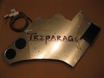
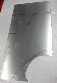
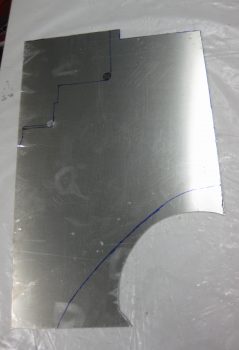
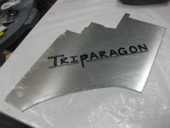
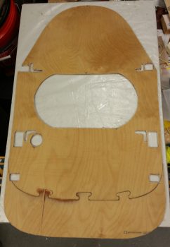
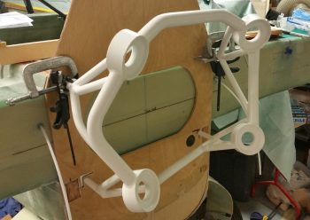
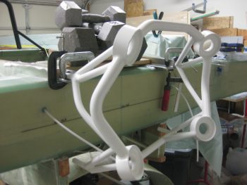
My Triparagon that is… or at least I can say it’s getting much closer.

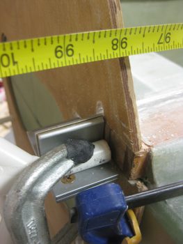
Today I did a fair amount of physical work on the Triparagon, but what’s not seen is the even more work I did in figuring out optimized electrical component locations, hardware requirements, etc.  I also took a quick trip down to the Aviation Dept. at our favorite Orange & Blue big box stores to pick up a few stainless steel screws, etc.

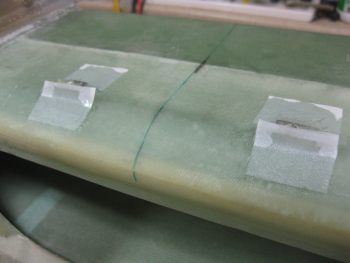
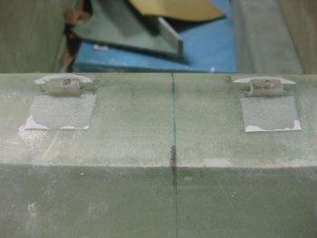
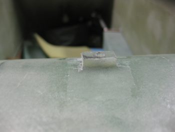
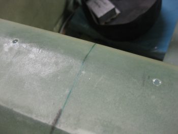
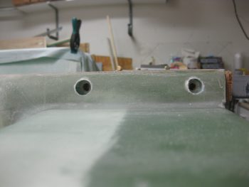
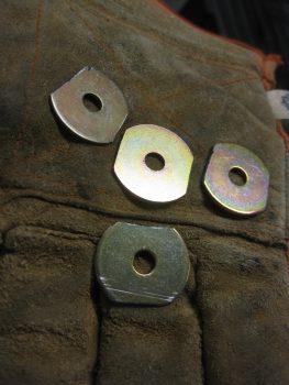
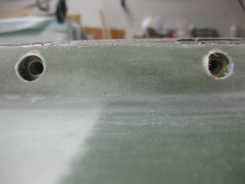
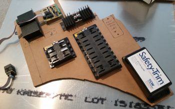
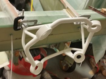
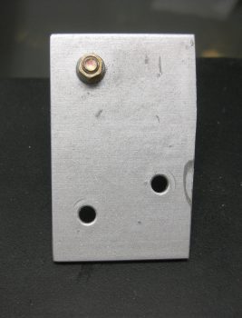
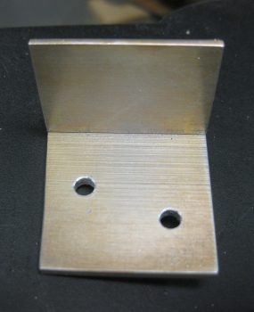
I started out on the Triparagon by positioning and then drilling the 4 mounting holes for the two AG6 Warning Annunciators that I’ll be using.  The pic below actually shows the Triparagon upside down.  I’ll be mounting the AG6 Annunciator boards back-to-back, one on each side of the Triparagon, with a long #6 screw attaching one side to the other at each corner of the AG6 board.  Also, although not shown here, immediately following my drilling of the marked mounting holes in pic below, I drilled a fairly large lightening hole in the Triparagon plate immediately underneath/between the two AG6 Annunciator boards.

Triparagon AG6 Warning Annunciator mount holes

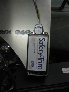
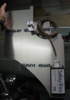
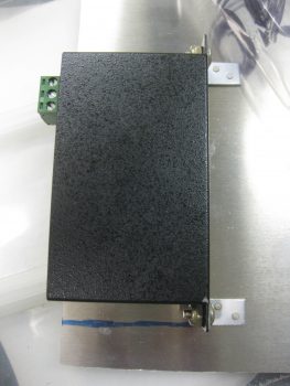
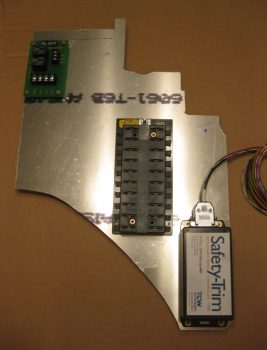
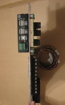
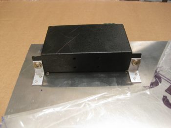
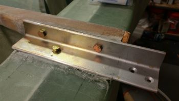
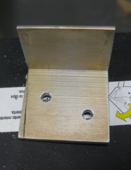
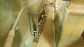
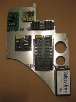
As for the right side Triparagon, besides the AG6 Annunciator board I also mounted the Schottky Diode with its heat sink, and the X-Bus (just to the left of the Main buss in the pic below).  As you can see I also drilled 2 more large lightening holes just above the Safety Trim box.

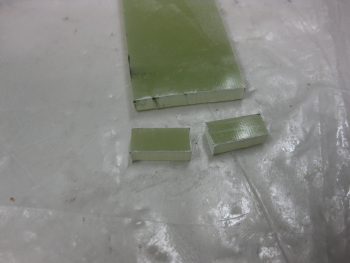
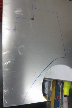
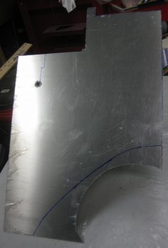
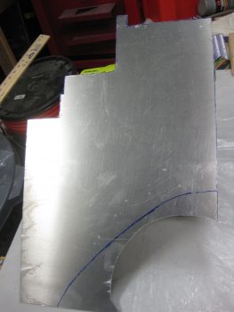
Immediately after I cut the Triparagon to shape, I weighed the panel at 1.38 lbs.  After the 3 total lightening holes that I drilled out today, it’s weighing in at about 1.15 lbs.  My goal is to get the Triparagon’s vertical plate weight down to about 0.6 lbs, with a total weight at under 1 pound.

Triparagon right side

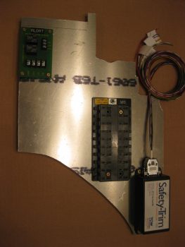
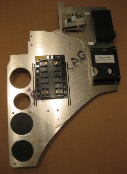
On the left side I added the twin AG6 warning annunciator, as well as the E-Bus that shares the two top bolts for mounting with the Main Buss on the right side.  In addition, I mounted the Flight Data Systems’ GD-40 Carbon Monoxide Detector.  I’d like to point out that although the CO detector may look a bit bulky in the pic, it’s actually very light and only weighs a few ounces.  Today actually marks a pretty cool milestone considering that all my busses are in place and ready to be wired up & installed with the Triparagon into the plane!

You may have noticed a couple of slots that I “machined” (Ha!  That translates to “Skil Saw”) along each side of the Main Bus, and thus on each side of the E-Bus.  These slots are nothing more than wire management slots that will allow me to secure the wires to the Triparagon with either zip ties or cable lace.  They are clearly in a very rough state, as is the entire Triparagon actually, and will be cleaned up later.

Triparagon left side

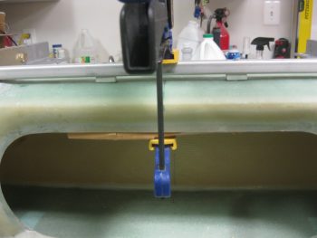
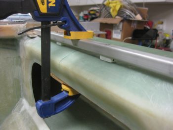
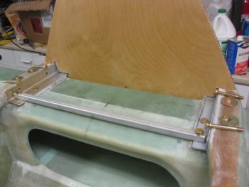
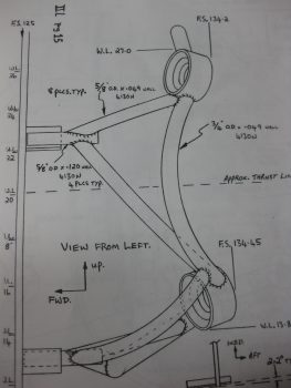
Obviously I’m trying to get the majority of electrical components mounted to the Triparagon, which then allows me to determine hardware, space, wiring, and connector requirements now so that I’ll have as much of it as possible on hand for when I hard mount the Triparagon into the front of the plane.  I’m thinking one more good day on this baby, then on to working on the wheel pants.  I should also point out that once the Triparagon meets my design & operational requirements, I’ll mount it into the fuselage directly behind the F22 center post with around 6 each K1000-3 nutplate assembly hardpoints.  The nutplate hardpoints will allow me to remove and install the Triparagon whenever I need to during the build, and of course after the build as well!


Chapter 14/22 – More of the same…

I started out today by gathering up the upper GIB seatbelt straps to modify them to work with my seatbelt cross bar configuration.

GIB upper seatbelt straps

I took a big breath and marked the mounting brackets for cutting with my ‘Dremel’ tool.

Seatbelt strap brackets marked for cutting

Here’s a closer shot of my cut marks on the seatbelt brackets.

Seatbelt strap brackets marked for cutting

I then took an even bigger breath and cut the seatbelt mounting brackets at the lines I had marked.

Seatbelt strap brackets cut

These brackets are some tough metal and I really had to put some oomph into it to pry the cut sides apart to slide out the seatbelt webbing.

Seatbelt strap brackets cut

Here’s a shot immediately after I removed the seatbelt mounting bracket from the webbing.

Seatbelt straps free of brackets

And here’s a shot of both upper GIB seatbelt web straps sans mounting brackets.

Seatbelt straps free of brackets

Now, obviously I had made a decision and planned on going the route of using a crossbar for the GIB upper seatbelt straps, but before I actually glassed in the support spacers, I did want to ensure that the seatbelt straps would work in their “new” (compared to plans) position.  Of course everything looked & worked fine.

Seatbelt straps mocked up on cross bar

I put the firewall up & added the “Vault” (headrest & component housing) to get an idea of how it all looks and fits together.

Seatbelt straps mocked up on cross bar

Here’s some closer shots, essentially the same as above.

Seatbelt straps mocked up on cross bar

Seatbelt straps mocked up on cross bar

One thing that I really like about this mod is that it allows the GIB to strap in with the upper seatbelt straps up to 3″+ inboard of the stock plans strap placement.  I really do think this will add a lot of comfort for the rear-seater . . .  or maybe better stated: won’t add any discomfort from too-wide, off-angle upper seatbelt straps.

3" further inboard strap placement

With the final hurdle cleared, the mod was a full go!  Time to get the support spacers in for good.  I 5-min glued the support spacers in place on top of the CS spar.

Seatbelt crossbar support spacers glued in place

Here’s are some aft shots of the support spacers 5-min glued in place.

Seatbelt crossbar support spacers glued in place

Seatbelt crossbar support spacers glued in place

I then whipped up some epoxy & flox using fast hardener.  I added a small flox fillet to the forward & aft sides of the seatbelt crossbar support spacers.

Seatbelt crossbar support spacers flox fillets

Here’s a closeup view of a flox fillet on the support spacer.

Seatbelt crossbar support spacer flox fillet

I then prepregged a 1-ply piece of scrap BID and laid up one ply on the forward and aft sides of each of the two support spacers.  As you can see, I then peel plied the layups.

Seatbelt crossbar support spacers glassed in place

Again, here’s an aft shot of the 1-ply BID layups on the seatbelt crossbar support spacers’ layups.

Seatbelt crossbar support spacers glassed in place

While my support spacer layups cured, I tried to accomplish something that I couldn’t do last night: find & buy a 10-32 threaded tap to allow me to bolt my stuff to the Triparagon.  I looked at 5 places near my house, and none of them had one.  I then went down to the Lowe’s in Potomac Mills and they had one.  I snatched it up before heading out to dinner.

After dinner, I returned home and quickly put the tap to work.  I drilled and tapped the 4 holes to mount the TCW Safety Trim module.

TCW Safety-Trim screws tapped into Triparagon

TCW Safety-Trim screws tapped into Triparagon

I then grabbed a 1/16″ thick piece of angled 6061T6 Aluminum and made 2 small mounting brackets for the 4-port USB hub (used for the GRT EFIS).

Mounting 4-port USB hub to angle brackets

I drilled and mounted the L-brackets to the USB hub mounting tabs, then clamped that entire assembly to the left aft side of the Triparagon.

Mounting 4-port USB hub to angle brackets

I then drilled 2 holes in each tab for rivets.

4-port USB hub angle brackets drilled for rivets

And then riveted the tabs to the Triparagon.

USB hub angle brackets riveted to Triparagon

I then broke out my German hole saw to drill 2 large lightening holes under the area where the TCW Safety-Trim is mounted.  I have two of these type hole saws from Germany, which is a good thing since I broke the first of those tonight.  The ensuing drama at the time is why I don’t have a final pic of the lightening holes, but there is a pic later in this post with the lightening holes visible.

German hole saw for cutting lightening holes

After messing around drilling the lightening holes underneath the Safety-Trim box, I then dropped the Triparagon stuff to clean up the cured GIB seatbelt crossbar support spacer layups.

GIB seatbelt crossbar support spacers layups cured

Below are pics of the cured left support spacer, and then the right, respectively.

Left seatbelt crossbar support spacer layup curedRight seatbelt crossbar support spacer layup cured

And another shot from the aft side of both seatbelt crossbar support spacers glassed in place.

GIB seatbelt crossbar support spacers install complete

After I pulled the peel ply & cleaned up the cured GIB seatbelt crossbar support spacer layups, I then drilled, tapped, and mounted the Main Power Buss and the roll trim relay board onto the right side of the Triparagon.  I realize that the 2 pics are close, but one is at a slight angle, so I left it in.

Right side Triparagon components install

Right side Triparagon components install

Here’s a pic of the left side Triparagon with both the 4-port USB hub and the lightening holes behind the TCW Safety-Trim box.

Leftt side Triparagon component install

Here’s a shot from the aft side showing the aft profile width of all the Triparagon-mounted components thus far.  The spacers under the roll trim board will be replaced with the correct size.

Aft view of Triparagon components

Finally, here’s one more shot of the 4-port USB hub mounting brackets riveted in place on the Triparagon.

USB hub and brackets installed to Triparagon

Tomorrow will most likely be a light build day, plus I need to get back to studying some for flying next week.  I’ll be working on the Triparagon a bit here & there, but next week I want to start back in on the Wheel Pants and knock those out!


Chapter 14 – GIB Seatbelt Bar

My first task of the day was to figure out the exact dimensions of the Triparagon component shelf that will primarily serve as a mounting location for the GRT GADAHRS, Trig TT22 Transponder, and the M760REM COM2 radio.  To minimize space, and to allow for a smaller shelf (e.g. less weight), I decided to mount the M760REM radio on the bottom side of the Triparagon component shelf.  As you can see, looking at the Triparagon from either straight aft or from the front, it looks like a big “T” . . .  thus, it has three main mounting arms, which is the reason for the “Tri-” in the name.  Moreover, weird names are conversation starters & keep life less boring!  Right?!

Triparagon Top Component Shelf

I started off my shop work today by figuring out the exact dimensions & locations of the support spacers for the GIB seatbelt crossbar. The spacers will be a couple of inches from the CS spar CL on each side.  Since the right side arm rest and right side horizontal part of the engine mount extrusion are both wider than their left side counterparts, I decided to skew the seatbelt straps over about a quarter of an inch to the left as well.

Configuring GIB seatbelt cross bar inboard mounts

I marked the spots where the initial holes would be drilled for the eventual installation of AN3 countersunk screws.

Configuring GIB seatbelt cross bar inboard mounts

I then drilled my marks with a small 1/16″ bit through the square upper seatbelt crossbar tube and into the top of the CS spar, but not all the way through.

GIB seatbelt cross bar mount holes drilled

I then drilled a series of holes with increasingly bigger sized bits… again, only down until I felt the tip of the drill bit hit the bottom side of the upper inside CS spar skin (on the inside ceiling of the spar).

GIB cross bar mount holes drilled out

Once the holes were decent sized, with still a bit more to go for the screws to fit, I stopped drilling for the time being.

GIB cross bar mount holes drilled out

And pulled off the seatbelt crossbar to expose the holes.  I then spent a good 45 minutes using a scribe to dig out the foam through these holes and shop-vac’ing the chunks out.  I essentially created an open cylinder under each hole all the way down to the bottom/inside CS spar skin (remember, I DIDN’T drill all the way through).  I would say the resulting air pocket I made for each hole was about .6″ to .8″ in diameter.

GIB mount holes drilled out on CS spar top

I then made up some wet flox with fast hardener and poured it into the air pockets I created under each hole in the CS spar.  As you can see, I’m simply making hard points in the CS spar to secure the center GIB seatbelt cross bar screws.

Wet flox for GIB cross bar mount hard points

With the leftover flox I then installed the right side modified AN970-4 washers after slathering them with flox.   After the washers were in place I installed the AN4 bolts. As you can see in the pic below, I have some trimming to do on some of each washer peeking out, but overall I’m very pleased with these washers and am very glad I did this mod.

Right side engine mount extrusion bolts installed

Here’s the flox curing inside the GIB seatbelt crossbar inboard mounting screw holes.

Wet flox in GIB cross bar mount hard points

I grabbed a bar of G10 Garolite that I had on hand and sanded down one end so that it was the same thickness as between the top surface of the CS spar and the bottom side of the GIB seatbelt crossbar (approx. 0.2″).

Shaping G10 Garolite seatbelt bar supports

I then flipped it over and marked it to make 2 support spacers for the inboard crossbar screws.

Cutting G10 Garolite seatbelt bar supports

I started by making a center cut that will result in 2 x 0.75″ wide pieces.

Cutting G10 Garolite seatbelt bar supports

I then cut across the G10 to give me the 2 support spacers measuring 0.75″ wide x 0.4″ deep x ~0.2″ thick.

Cutting G10 Garolite seatbelt bar supports

I then set the spacers in place and clamped the GIB seatbelt crossbar over them to secure them in place.

G10 seatbelt bar supports clamped in place

I then drilled a series of holes starting from smaller to larger both through the G10 and also down all the way through the CS spar into each of the hard points.

G10 seatbelt bar supports clamped in place

I then actually drilled the holes out all the way with a #12 bit to accept an AN3 screw.

G10 seatbelt bar supports clamped in place

I drilled countersinks into the freshly drilled crossbar mounting holes and then installed a couple of AN3 screws into the holes. You may also note that the left side bolts are installed securing the engine mount extrusion to the longeron –utilizing the modified AN970-4 wide area washers of course!

Left side extrusion bolts into longeron

It took a bit of fiddling about with the holes to get the screws to slide in without being “motivated,” but after a good 10 minutes everything was working fine.

GIB seatbelt crossbar screws countersunk

Here’s one last shot of the temporarily mounted GIB seatbelt cross bar & the 6 (six) permanently mounted AN4 bolts securing the upper engine mount extrusions to the CS spar and the longerons, respectively.

GIB seatbelt crossbar screws countersunk

Tomorrow I plan on floxing & glassing the support spacers into place for the GIB seatbelt cross bar.  I’ll also be doing a fair amount of work on the Triparagon as well as prepping for starting back on the wheel pants install next week.  I failed to mention that at one point today I drug the table saw out and cut the top component shelf for the Triparagon.  I took a pic of it, but it was horribly blurry . . . so imagine a rectangular aluminum plate 6.1″ x 9.4″ and your minds eye will have it!  ha!


Chapter 14 & 22 – Dinkin & Dunkin!

I did a project assessment last night and decided for a backup (COM2) radio that the remotely mounted PS Engineering M760REM will do fine for what I need a radio in that role to do.  I’m trying to optimize my funds, and using the M760REM vs. the sexier Trig TY-91 radio saves me a good $500.  Since the majority of my comms will be via the COM1 radio in my GPS unit, I’m good on this being the right decision.

Today I spent over 5 hours doing research and updating a number of electrical diagrams, in part to re-wicker them to include the M760REM radio into the mix.  There were a few other glaring things (such as COM1 & COM2 radio assignments) that I had just never got around to cleaning up.  I’m lame right now with a cold, so I figured I could justify “taking a half day off” from building to get some cleanup tasks on the electrical diagrams knocked out.  In addition, I added the items I just recently ordered from Stein, the Cozy Girrrls and Amazon to my parts tracking spreadsheet. Lastly, I spent a good 20 minutes on the phone with a Dynon tech to verify that my proposed wiring for the M760REM radio was correctly in sync with the Dynon intercom box that I’m using.

After all that was out of the way I grabbed a quick dinner and then headed down to the shop.  My goal this evening was to make some noise!  Specifically, I wanted to get the vertical plate of the Triparagon cut and all the holes and hardware configured for bolting the upper engine mount extrusions in place to the longerons & CS spar.

I started with the Triparagon.  I had outlined the final shape on the same piece of 0.090″ 6061T6 Aluminum that I used for the brake heat shields.

Triparagon outline on 0.09" 6061T6 plate

I loaded up my Skil saw with a finer tooth blade and ripped the Aluminum plate to produce the aft edge of the Triparagon.

Triparagon aft edge cut from 6061T6 plate

I then cut out the Triparagon top edge.

Triparagon top edge cut

I drilled a large hole in two of the corners on the front side to create a nice radiused inside corner, then continued to use the Skil saw to cut the Triparagon to shape.

Triparagon forward top corner cut

I finished all the areas I could on shaping the Triparagon that required the Skil saw.  I then switched to using my Jig saw to cut the rest.

Triparagon mid/forward area cut

And here it is!  The vertical Triparagon plate is cut to shape, and thus the first step of many is complete in the creation of the Triparagon ….

Vertical Triparagon plate shaped!

With the Triparagon cut, I then moved on to the upper engine mount extrusions.  I grabbed a 1/2″ drill bit and used it to ream out the glass & foam surrounding the outboard bolt holes in the longerons.

Outbd top engine extrusions reamed to 1/2"

To avoid the same issue that we have when mounting the landing gear extrusions with small washers in subsequently having them embed themselves into the comparatively soft Spruce structures, I decided to use AN970-4 washers on the outboard side of the bolts holding the engine mount extrusions to the longerons.

I started by marking a line the width of an AN970-4 washer over each hole right at the junction of the outboard longeron edge and the attached foam and glass.  I used the Fein saw to cut a slot over each hole.  I then used a 1/16″ drill bit in a cordless drill to carefully “grind” out the foam to enable me to slide an AN970-4 washer into each slot.

As you can see by the pic below, in standard configuration the AN970-4 washers are too tall and peek out of their slot.  I expected this would most likely be the case, so I simply marked each side of the washers and used my Dremel tool to shape them.

AN970-4 washer slots cut adjacent to longerons

Here are the 4 outboard AN970-4 washers shaped to fit into the slots I made on the outboard sides of the longerons (… without poking out).

Washers trimmed for outbd longeron positions

Here’s a shot of the port-side longeron with the engine mount extrusion holes.  You can clearly see the modified AN970-4 washers through the outer 1/2″ holes.

Outbd extrusion bolts AN970-4 washers in place

After I got the washer slots made and the AN970-4 washers trimmed to fit, I then moved forward with sealing the bolt holes that I drilled through the Spruce wood hard points.  Per the latest CSA and in conversations with Terrry Schubert, apparently over longer periods of time the bolts will actually start corroding due to the moisture in the wood.  To remedy this, any bolts placed through wood should have the bolt holes sealed with epoxy first.

I didn’t know about this nor did I do it on the main gear bolts, so I’ll just have to remain vigilant and watch those bolts.  But from here on out all bolts & screws mounted through wood will have the wood holes sealed first.  As per Terry in the latest CSA newsletter (October 2016), the way to do this is to mix up some epoxy and then simply add just a bit of alcohol to the mix.  Apparently this allows the mixture to flow much better and really seep into the wood.  The one thing I had forgotten before I reread it tonight is that it takes multiple coats to seal the holes… so no finalizing the extrusion mounting tonight!  Again, as per the CSA plans I used a Q-Tip to apply the epoxy/alcohol mix into each hole.

Alcohol laced epoxy to seal wood extrusion holes

As my first round of epoxy/alcohol mixture was curing inside the wood bolt holes, I went through the process to Alodine the two 2024T3 inserts in each end of the GIB upper seatbelt bar.  I first submerged the pieces in Alumaprep for about 3 minutes, giving them a good scrub about half way through.  Then I rinsed them thoroughly and set them in place in the Alodine as you can see in the pic below.  I let them sit in the Alodine for just over 3 minutes . . .

GIB top seatbelt bar 2024 end inserts Alodined

And then again rinsed them thoroughly with water.  I then let them dry out on a paper towel, as you can see below.

GIB top seatbelt bar 2024 end inserts Alodined

Before calling it a night, I applied one more (and final) coat of the epoxy/alcohol mixture to the top engine mount extrusion bolt holes in the Spruce hard points.  I’ll let this cure overnight then start tomorrow by actually bolting the upper engine mount extrusions in place.

In addition, I plan to work on the GIB upper seatbelt straps crossbar since I would like to get that checked off the list.  Finally, I may cut the small top shelf cross piece for the Triparagon.  I’d like to get all these tasks wrapped up so that next Monday I can start back on the wheel pants install.  Allowing for my flight lessons of course! (clearly I’m not flying now due to this cold).


Chapter 14 – Upper Extrusions

I spent a good majority of yesterday studying to get back into the groove for an Instrument flying lesson I had this morning.  Me and my new instructor flew south out of the SFRA, did a couple of holds off of Stafford before flying an approach and practice missed approach at Stafford.  If felt good to be back flying, even if it is training.  But enough about that . . .

Today I started off by shipping my 8″ prop extension back to Sam at Saber Manufacturing so he can drill the holes & insert the required 3/8″ bushings (in-between the 1/2″ holes I currently have) in order for me to mount the Silver Bullet prop.  Of course, originally, I had planned on going with a 3-bladed Catto prop which required 1/2″ prop bolts as per Craig Catto.  In addition, Sam will swap out my 1/2″ prop bolts for 3/8″ ones and swap out the crush plate with one that has 3/8″ holes.  It’s never-ending on these adjustments, eh?!  One change is never without its 2nd, 3rd and 4th order affects!

I then finalized the dimensions of my cardboard Triparagon template and then traced it out onto my 0.090″ thick sheet of 6061T6 Aluminum (the same sheet that I used for my gear heat shields).  I didn’t get the Triparagon cut out tonight, but will do so within the next day or two.

Marking Triparagon sheet aluminum

What I did get cut tonight was the 1/2″ x 1/2″ square 6061T6 Aluminum tube that I’m using in lieu of the plan’s GIB upper seatbelt mounts.  This tube will allow the upper seatbelt straps –with the webbing merely wrapped around it– to slide inboard and outboard to allow the GIB to have a much better variance in adjusting the upper seatbelt straps to their comfort.

I started the process of drilling the holes for the seatbelt tube by marking the extrusions on each side with lines that extended beyond the sides and edges of the square tube.

6061T6 square GIB seat belt tube clamped in place

I then carried those lines back onto the top of each end of the tube to mark the center point for drilling on each side.  I finalized trimming 3/8″ x 3/8″ square 2024T3 inserts, each about 1.25″ long, that slide into place on each end of the tube with the outside face of the inserts close to flush on the each side.

Left side GIB seat belt tube marked for drilling


Right side GIB seat belt tube marked for drilling

I started with a small drill bit about 1/16″ thick and then stepped my way up until I had a 1/4″ hole drilled down through the seatbelt crosstube ends into the extrusions and then through the Spruce hardpoints embedded in the CS spar, respectively of course.

Left & Right forward 1/4" holes drilled

Here’s a closer shot showing the forward bolt hole on the right extrusion very close to the same spot as my original mark.  Up on the longeron is the end of the GIB seatbelt cross tube with the 1/4″ bolt hole drilled through it as well.  In this pic you can see the 2024 insert in place (very snugly) in the end of the tube.  I’ll remove the inserts and Alodine them before re-inserting them before the final mounting of the seatbelt cross tube.

Right side 1/4" holes drilled

With the GIB seatbelt cross bar mod and the fact that my longerons are wider in the back than stock, it took me a good 20 minutes to figure out the best length of AN4 bolts to use in all but the aft horizontal bolt position on the extrusions (which is the stock plans size bolt obviously).

Upper engine mount extrusion bolt selection

Here’s another shot of the bolts that will get mounted into the upper right engine mount extrusion, right longeron, and CS spar hardpoint.

Right upper engine mount extrusion bolts

Here’s a shot of the all the upper extrusion mounting hardware.  As you can see, I also put the firewall back in place.

Upper engine mount extrusion bolts

I then did a quick check to see how my GIB headrest / component shroud fit & looked (maybe I’ll start calling it something a bit catchier like, “the vault” or something).

GIB upper seatbelt strap crossbar & component shroud

It fit fairly well.  Of course some minor tweaking will be in order, but so far I’m happy with the configuration back here with the D-Deck and all.

GIB upper seatbelt strap crossbar & component shroud

Tomorrow I’ll continue to work getting the extrusion mounting bolts installed.  First, I’ll prep the holes in the wood using epoxy with a little bit of alcohol added to it as per the latest CSA newsletter (Oct 16).  I’ll also work on the GIB seatbelt upper strap bar and try to get the Triparagon cut out and maybe work on that a bit.  As soon as I get the bolts installed and the seatbelt cross tube finished, I’ll then finally start back on the wheel pants before rolling into the nose and canopy builds.


Chapter 4/14/22 – Firewall & Electrical

Today was another light build day since I went to a Fall Fun Festival with some friends.  I did get a bit done, starting off with some of what I worked a little bit on yesterday, then finished up quite a bit today: my “Triparagon”.  Or, basically the big motherboard for the vast majority of all my electrical system components: busses, grounding blocks, etc.

Since I now know exactly how my canard controls fit into the forward fuselage/nose, I was able to tweak the size & dimensions of the vertical Triparagon plate.  I recut another fresh, updated cardboard mockup and then set about figuring out the placement of my electrical components.  I’m extremely pleased with the fact that I’ll easily fit virtually my ENTIRE electrical system on this one plate.  And the only reason I say “virtually” is due to any future potentiality that I may have a component that doesn’t fit on the Triparagon, but currently EVERY piece of the electrical system fits on it!

Triparagon

I then spent a good half hour between removing the peel ply off the firewall front face 1-ply BID layup and then razor trimming the edges.  The firewall looks good and is very close to getting  mounted.  I do have to do some minor sanding along the edges and a couple places on the front face, and quite a bit on the aft side since I didn’t peel ply it for some odd reason (that was back in 2011, so my memory is foggy on why I didn’t peel ply it! . . . )

Firewall - forward side BID

I then spent another good 45 minutes looking at the configuration of stuff on my D-Deck area.  The 1/2″ square 6061T6 bar that you see will traverse across the fop front side of the CS spar, attached at the front corners of the top engine mount extrusions.  Yes, this is a modification of the GIB seatbelt mounts and is NOT per plans.  This bar will be mounted with the AN4 1/4″ extrusion bolt on each end (with 2024 inserts inside each of the bar for strength) and also have center mount countersunk screws to keep it secure.  That will allow the GIB to simply slide the upper seat belt shoulder straps inboard or outboard for comfort.  I weighed all these components, and this modification is within an ounce (probably less) weight-wise as the plans configuration.

The black GIB headrest and components shroud cardboard mockup (that I made in Germany) is a modification I’m doing ala Wayne Blackler (see second below).  I like this configuration INFINITELY better than the plans shroud that has the GIB with their essentially in coffin or something…. Blech!  With my GIB upper seatbelt bar mod I did have to trim the depth by about 3/4″, but it still looks as if everything I had planned to get mounted inside the headrest will still fit comfortably.

D-Deck GIB headrest

Wayne’s GIB headrest and component housing:

Wayne Blackler's GIB Headrest

The next couple of days I have an out of town visitor coming in, so between football, cooking out, visiting, beer drinking, etc. not a whole lot of work will get done.  Plus, I’ll be prepping to get back into my flying lessons which start this Wednesday.  Of course I’ll still be working on the build, but it will be significantly less with all the flying I’ll be doing!


Chapter 4 & 14 – Extrusion & Firewall

Today was kind of a slow build day, but I did get a couple of things knocked off the list.

The first thing was I drilled the 1/4″ holes into the vertical leg of the upper right engine mount extrusion & through the longeron.

Bolt holes in engine mount extrusion

I then test fitted a couple of AN4 bolts in the holes.  Nice & snug and the holes look good.

Test fitting bolts in extrusion

I then backtracked to finish a step in Chapter 4 that is about 5 years late in the making: glassing the front face of the firewall with 1 ply of BID.  I had held off initially to wait to see if I needed to added any screws, etc. and just never got around to glassing it.

I used the firewall as a template to mark & cut the BID at a 45° bias.

Cutting BID for forward firewall face

I then took the firewall outside and sanded it down with a DA sander to prep it for glass.

Forward firewall face

I set the BID in place on the firewall then pulled it down and wet out just the top side of the firewall face.

Covering forward firewall face

Then I set the BID in place on the top side of the firewall, rolled the BID up towards the top and wetted out the bottom of the firewall face with epoxy.

Covering forward firewall face

I then wet out the entire BID on the firewall face.

Forward firewall face covered with 1-ply BID

With the BID wetted out on the face of the firewall, I then peel plied the entire layup.

Forward firewall face BID peel ply

Tomorrow I’ll pull the peel ply and clean up this layup.  I’ll also work some more on the upper engine mount extrusions to get them bolted in place, and then prep for glassing in the lower engine mount extrusions.  Once I finish with the engine mount & extrusions, I’ll be back working on the wheel pants again.


Chapter 14/23 – The Mount

First off, as per plans I let this the engine mount extrusions cure until late afternoon to ensure a complete curing of the layup.

I then cleaned up all the excess glass with the Fein saw and really gave both side layups a good sanding.

Cured/sanded upper engine mount extrusions

One reason I went with 4130 steel on the left side extrusion is that I wanted a higher strength extrusion than stock due to a much heavier and more powerful engine.  But I also wanted a low profile extrusion on the left side, since that’s where the passenger enters.  I understand it’s back on the spar and out of the way, but I did want no more than an inch high extrusion on the left side.

On the right however, where the canopy is, the extrusion is 1.25″ high.  The base leg is even wider at 1.5″ wide.  The upper right extrusion is of course 2024 Aluminum.   I pretty much left the thick pad of glass that I laid up between the right side extrusion upright and the longeron at the same 1.25″ height as the vertical extrusion leg, but I did taper it down into the longeron surface.  Still, the glass under both these upper extrusions is thick, stout & strong!

Cured/sanded upper engine mount extrusions

I then cut the pass through holes on the firewall for the engine mount extrusions.  I figured I would have to open up those pass through holes a bit, but it was really tough getting the firewall on.  And although I checked the lower longerons to see if anything was messing up the re-mounting of the firewall, I couldn’t see anything.

Trimming firewall for extrusion pass through

I opened up the holes based on what I thought was some binding, but I was bamboozled by the firewall in that the real problem was at the bottom, not the top.  Since the bottom longerons (or stringers) curve upward, then a bit more needs to be removed from their mounting holes to install the firewall with a straight in motion.

Trimming firewall for extrusion pass through

The next issue I encountered was the right engine mount extrusion 1.6″ bottom reinforcement & connecting plate.  Since it matches the 1.5″ width of the upper right side extrusion, and due to the slight angle that the extrusion is mounted to the longeron at, I simply just could not get the screws mounted into it because it kept hitting the firewall. Obviously, this clearance issue will only get worse when the Fiberfrax and Stainless steel final cover is added to the firewall.

So I marked a slight angle on the forward side of the 1/8″ reinforcement plate (it’s still attached to the outer angle that the engine mount tube is attached to).

Right upper engine mount bracket trim

I then trimmed the edge using the Dremel Tool (and a face mask of course!).

Right upper engine mount bracket trimRight upper engine mount bracket trim

I then was able to get the upper engine mount extrusion assemblies installed, and then clamped the engine mount in place.

Mocking up engine mount on firewall

By trimming the top engine mount posts by 0.32″ I am now able to easily attain the 134.2 fuselage station at the top aft engine mount ring.  I added a pic of the engine mount post so one can get an idea of how it will look bolted in place.

Got my FS 134.2!

Engine mount position for FS 134.2

I then focused on the lower engine mount posts for a bit.

Lower engine mount posts

The extrusion pass through holes needed to be modified just a bit, so I marked them up.

Re-marking lower engine mount extrusion holes

After mocking up the fuselage, it was clear that the lower engine mount posts were going to need a trim as well.  There’s no room for them and currently they would have to stick into the firewall for the bottom engine mount rings to be at FS 134.45.  I knew I was going to have to shave another 0.3″ off of each one.

I pulled out my Harbor Freight “Dremel” tool and realized the cutting wheel was pretty small and needed to be replaced.  Well, not wanting to waste it, I decided to cut some fairly thin tubing by lopping off the offending inboard rudder pedal tubes from each rudder pedal.

Taping rudder pedals for a trim

The Dremel made short order of the offending rudder pedal cross bar.

Rudder pedals trimmed!

I then remounted the rudder pedal.  You can see how way much more room I have with that inboard part of the cross-tube gone!

Checking trimmed rudder pedal fit

I then removed what was left of the small cutoff wheel and replaced it with a brand new one.  Then I got to work trimming 0.3″ off of each lower engine mount post.

Lower engine mount post marked for 0.3" trim

Here’s a shot with the engine mount post trimmed to length (minus 0.3″).

Lower engine mount post trimmed 0.3"

I set aside the trimmed engine mount & marked up the upper engine mount extrusions to be drilled in order to receive 1/4″ AN4 bolts.  Below is the right side with its drill bit holes marked.

Right engine mount extrusion holes marked

I then did the same for the left side.

Left engine mount extrusion holes marked

And here’s a shot of both sides . . . Ok, ready to drill!

Top extrusion bolt holes marked for drilling

I started drilling the right extrusion first.  Of course drilling straight down on these holes doesn’t present any real challenges . . .

Drilling top extrusion bolt holes

But Boy, drilling the side holes sure do!  I used a flexible drill shaft that I picked up from Home Depot a while back specifically for this purpose.

Drilling top extrusion bolt holes

I focused on the left side 4130 engine mount extrusion because if anything is going to tear up my drill bits, it will be this hard tough stuff (although its not anything near as bad as stainless steel!)

Drilling right engine mount extrusion holes

I rounded up some AN4 bolts and fit-checked the bolt holes.  Nice and snug!

Test fitting AN4 bolts

It got pretty late, so I needed to stop drilling for the evening, but here’s a shot of both sides with the their one bolt each installed.

Drilling upper engine mount extrusion holes

Finally, here are a couple pics off the top “ceiling” of the interior CS spar showing the nuts and large washers holding the bolts in the extrusions in place.  I am happy that my Spruce hardpoints embedded in the CS spar are in the right spot and that I’m hitting them with my bolts!

Test fitting AN4 bolt - Right sideTest fitting AN4 bolt - Left side

Tomrrow I’ll continue to work on the engine mount, the extrusions and the firewall, and of course I’ll continue to post my progress here.  Either tomorrow –or very shortly thereafter– or the next day I’d like to have the engine mount, et al, in the bag in order to move back onto the wheel pants.


Chapter 14/23 – Engine Mount

I started off today with something I was curious about, and that had nothing to do with the engine mount.  I really just wanted to see where a good location was for the fuel pump, and in relation to the fuel valve.  I played around with a few different locations, stopped at this one since I really like that the pump can be mounted vertically here, thus driving as much of the pump weight forward as practically possible.   It also gives some nice space to the fuel valve.

Fuel pump & valve mockup

I then moved on to measuring the top engine mount posts to take 0.32″ off the end of each side.

Trimming upper engine mount stems

Here is one of the posts after I trimmed it 0.32″.

Upper engine mount stems trimmed

I then started marking up the firewall to cut the slots so each engine mount extrusion could transit the firewall.

Marking engine extrusion passthroughs

Here’s a shot with both upper and lower engine mount extrusion slots shown marked for cutting.

Extrusion pass-throughs marked

I started each extrusion slot by drilling a few 1/8″ holes for the top extrusion slots and 3/16″ holes for the bottom extrusion pass-through slots.  I then transitioned to using a saber saw to finish cutting the holes.

Cutting extrusion pass-throughs

After finishing each hole with the saber saw, I then sanded down the pass throughs with 32 grit paper.

Cutting extrusion pass-throughs

Here’s a shot of the firewall mounted with all the engine mount extrusions pass-through slots cut.

Engine extrusion pass-throughs

I then set the engine mount extrusions in place to see how they looked & fit.

Engine mount extrusions in firewall

Here’s a closer shot of the engine mount extrusions.

Engine mount extrusions in firewall

I then tested out my trimmed engine mount by clamping it in place on the upper engine mount extrusions.

Mocking up engine extrusions & mount

Again, here’s a closeup shot of the upper right extrusion.

Engine mount closeup

Ahh, trimming the top engine mount posts did the trick.  Now I can dial in the upper engine mount rings to FS 134.2 as per plans.

Top engine mount at FS 134.2!

I then pulled the firewall off and mocked up just the upper engine mount extrusions before I glassed them in place.

Mocking up upper extrusions

After verifying that the extrusion spacing was good, I then went to town sanding the areas that will get glass during the mounting of the engine mount extrusions.

Sanding in prep for glass

I then vacuumed up all the sanding dust.

Prepped for glass

I have to say that this is quite a detailed layup.  The time lapse between the pic above and below is over 4 hours.  Regardless, here are a couple of shots with the upper engine mounts glassed & floxed into place.

Upper extrusions glassed/floxed in placeUpper extrusions glassed/floxed in place

And a shot from the aft side , , ,

Upper extrusions glassed/floxed in place

I then verified that the left side extrusion’s firewall alignment mark was good, which it wasn’t.  So I spent a few minutes tweaking both side, then once I got them straight, I snapped this shot.  The line at the top equates to the forward side of the firewall, while the bottom line equates to the aft side of the firewall…  Thuss why I paid so much attention to getting these marks aligned properly.

Left extrusion firewall hash marks

Here’s the right side extrusion firewall alignment mark.  Due to the angle of the camera, the extrusion and the spar, it looks a bit off.

Right extrusion firewall hash marks

But if you look at it from this angle, it’s spot on.

Left extrusion firewall hash marks

Wth my upper ending mounts aligned properly, I then wanted to better align the bottom engine mount rings.  You’ll note in the pic of the plans below, the upper engine mount ring ends at FS 134.2, while the bottom engine mount ring ends at FS 134.45… 1/4″ aft of the upper engine mount ring.

Engine mount fuselage stations

I used my level and a 1/4″ block of aluminum to check the lower engine mount rings for the proper fuselage station.  They were just a bit aft on the bottom side, but a slight push forward got them to the proper fuselage station.

I strapped the bottom of the engine mount to the center of the landing gear to create just a slight bit of pressure, which got the lower engine mount rings to the correct fuselage station.  Since the epoxy will still a bit pliable and not cured yet (I used slow hardener for this layup), this should set up the correct fuselage stations for the top & bottom of the engine mount.  At a minimum, it will get the engine mount rings very close to the required FS settings so as to minimize stress when the mount gets bolted into place.

Lower side mount strapped for FS 134.45

Here’s a shot of the aft end of the fuselage with the engine mount being used to ensure the upper engine mount extrusions are set in their correct positions.

Lower side mount strapped for FS 134.45

Tomorrow I’ll clean up this layup and then continue to press on to get the engine mount ready for install.  I’m not sure if I’ll tackle the lower extrusions yet since I’ll have to assess the pros & cons of flipping the fuselage or using Cab-O-Sil and simply working the layups upside down.


Chapter 14/23 – An Enigma . . .

Before I get to the “enigma” part of this story, I wanted to show you one piece of what Marco & I were into last night.  We started off out in the shop and of course had a myriad of discussions on all things Long-EZ.  He brought some Long-EZ seat cushions he has and we tried them out both in the front & back seat.  This visit is the first time Marco has sat in my fuselage, and he did note the difference in feel between my 1.4″ wider cockpit vs. his stock flying plane (he widened his build Long-EZ fuselage 2″).

The more exciting part of his visit is that right before we went to dinner I hooked up a 12v battery to charge while we were out. Then, when we returned, we fired up the GRT Mini-X EFIS for the first time ever.  Marco was curious to see how it looked and requested that we take a look, so we messed around with the screens, menus, features, etc. for a good while. We didn’t take any pics last night, but below is some of what we saw with just power and the GPS antenna hooked up to the Mini-X.

Primary Flight Display (PFD):

GRT Mini-X PFD

Navigation Maps (Track up & North up):

GRT Mini-X MapGRT Mini-X Map

HSI:

GRT Mini-X CDI

Today I started out by lifting the fuselage nose to get the longerons to a level 0°.

Setting fuselage to 0 degrees

Longerons at a level 0°.

Setting fuselage to 0 degrees

I then checked the firewall and it was dialed right in at 90°, perpendicular to the longerons.

Firewall at 90 degrees

I calculated the thickness of the firewall (since I haven’t glassed on all the BID yet) at 0.355″ and simply rounded that up to 0.36″ and added it to the 1.6″ for the part of the engine mount extrusion sticking out aft of the firewall for the engine mount to attach to.

Marking extrusion at 1.96 inchesMarking extrusion at 1.96 inches

After removing the firewall, I mocked up the engine mount extrusions (remember, the top ones are a mixture of 4130 steel on the left side and 2024 aluminum on the right) and then checked the WA16 Spruce wedge spacers.  Since my fuselage is just slightly more curved, I cut the WA16s 0.4″ at their widest point vs the stock 0.3″.  This of course turned out to be a wasted effort since even though the fuselage is more football shaped than stock, the plans 0.3″ wide wedge spacer dimension is still the correct size.  Ahhh, so I did even more cutting and sanding to get these things thinned down.

Engine mount extrusions in place

I then clamped and set the engine mount into place, only attached to the upper engine mounts for the initial look.

Engine mount setupThis is where the ENIGMA part comes into play.  I have no idea why, since I thought I was Uber diligent in my measuring of all fuselage dimensions at the beginning of this build, but the face of my firewall is setting at about FS 125.4 vs the plan’s FS 125.0.  I have to admit I was remiss in double-checking the firewall dimensions when I installed the CS spar into the fuselage, since I assumed that my spar notches were good due to the fact that I did re-check their measurements.  Plus, the firewall fit flush and appeared aligned, which it is . . . just 0.4″ aft where the face of it should be.

The real affect, although over-comeable, is that the top set of engine mount brackets are setting at FS 134.5 vs FS 134.2.  0.3″ may not seem significant, but it certainly is to the W&B when you’re talking about the mounting of the 250+ pound engine, the heaviest component on this entire craft.

My initial concern was that if I simply move the mount closer (which will require some trimming of the upper engine mount stems) that it would negatively effect the clearance of the forward-mounted engine components.  But since I’m using Electronic Ignitions in both magneto mounts, they won’t require the forward space that Slick mags do.  Thus, if I trim a hair over 0.3″, and mount the engine with it’s normal engine mount stem to firewall spacing, I should be very close to spot on with the FS 134.2 engine mount setting.

[BTW, the measurement below was taken from the face of F28… so, 28 + 106.5 = 134.5].

Engine mount 0.3" too far aft

This shows the gap between the end of the right longeron and the upper right engine mount stem.  Note that if the engine mount stem were left at the length in the pic below, it would actually be embedded into the firewall.  The aft face of the firewall will be just forward of the double horizontal extrusion plate shown just underneath the engine mount stem.

Engine mount to longeron spacing

Tomorrow I’ll actually trim the engine mount (too late tonight due to noise) and continue to work the engine mount extrusions.  I do plan on getting the layups & upper engine mounts in tomorrow.  Also, as you can see –at least for the time being– I’m pretty much done with Chapter 16, Controls.  Finally, there’s some important info concerning my upcoming build schedule in the project update post.