Chapter 16 – The end is near!

I had a lot of running around to do today, so by the time I got home it was actually late afternoon.  The weather is still unseasonably warm, so I figured since it was nice out and NOT raining, I would get some more outside work done.

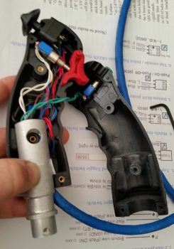
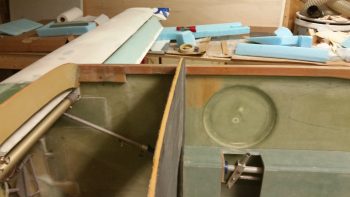
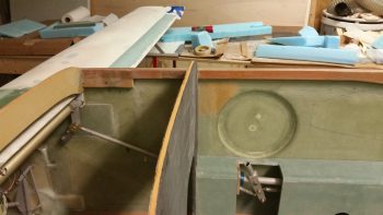
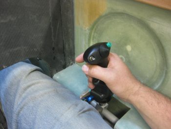
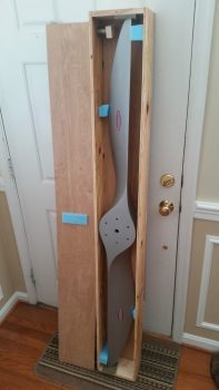
Now, I may have mentioned it before, but I haven’t put a lot of emphasis on it . . . yet.  But I’m essentially reverting back to the very first week of this project and slowly cutting all the pieces for a front seat, instrument panel & avionics bay mockup, or simulator, of my Long-EZ (See my Initial Project Planning page for an idea).  This will allow to test locations of instruments on the panel, for both actual spacing & location preference, and also will allow me to work through the manuals with the instruments powered up in front of me so I can input all the settings in the actual cockpit environment.  Serendipitously, I now have both an Infinity stick and a spare throttle quadrant to use in “the Sim.”

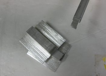
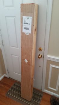
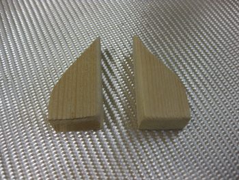
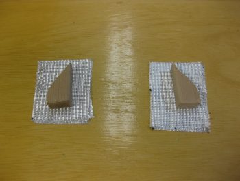
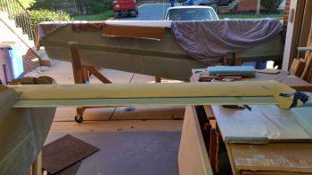
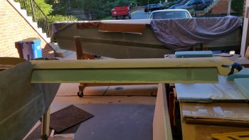
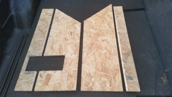
Since I have most of the pieces cut already, the main parts that were missing were the armrests.  Since I reconfigured my outside shed, I know have access to my router table and it still has the round-over bit that I used on the real armrests… and still set at the exact same position!  So I cut these pieces, rounded them over along the top edge pieces and then notched the right side armrest for the control stick.  This will be a project for when it gets super cold this winter, or snowed in, etc.

Fuselage SIM mockup armrests

Ok, so I would consider this next part Chapter 12, mounting the canard.  But it’s good to mix it up a bit eh?  I hope you answered yes, otherwise I’m sure my blog is a lesson in futility for you.  ha!

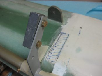
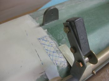
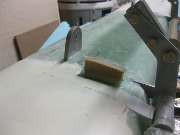
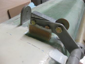
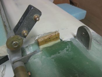
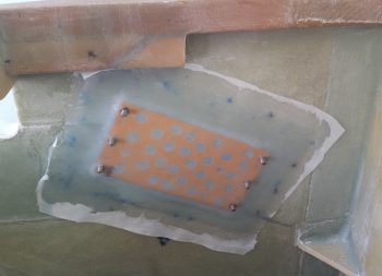
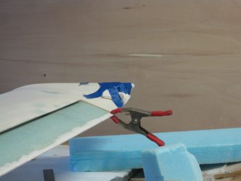
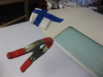
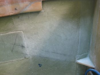
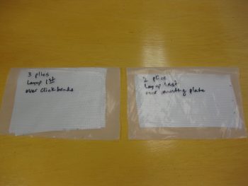
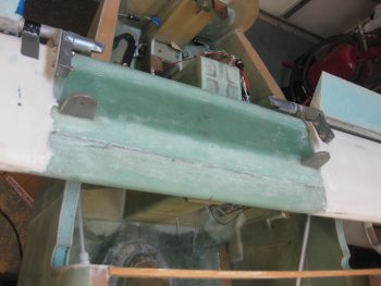
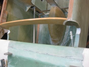
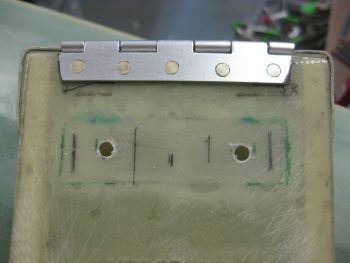
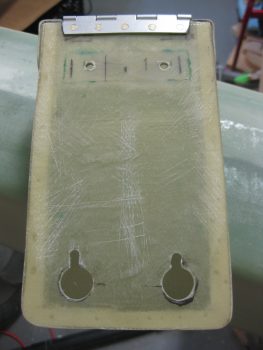
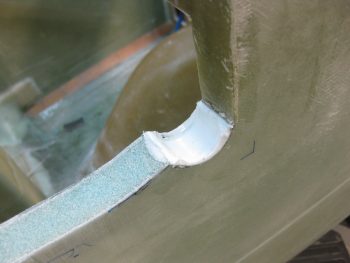
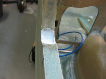
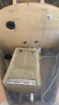
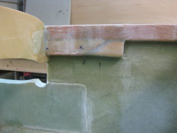
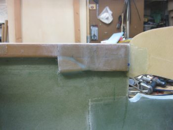
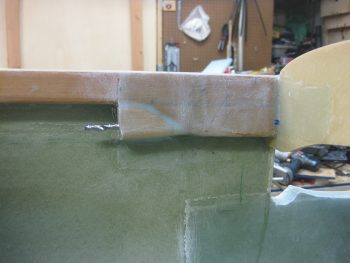
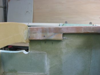
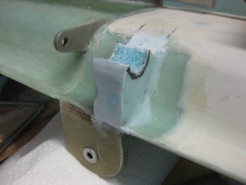
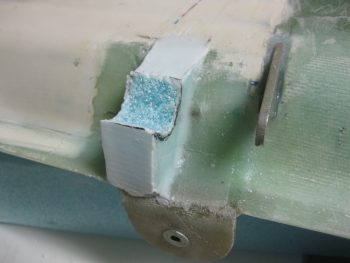
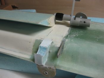
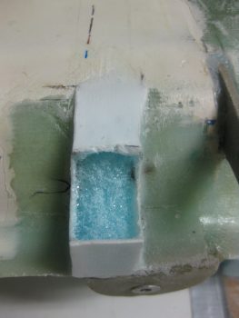
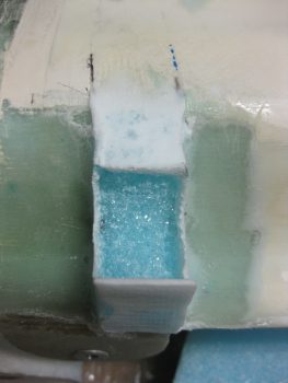
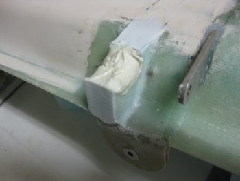
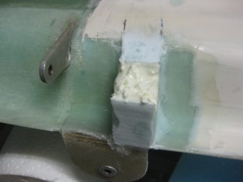
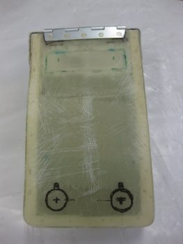
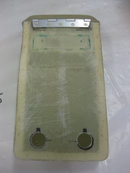
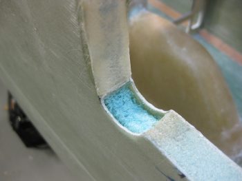
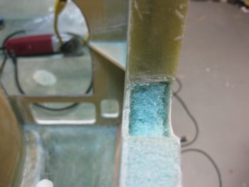
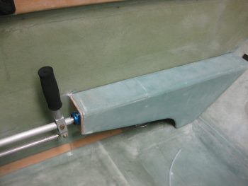
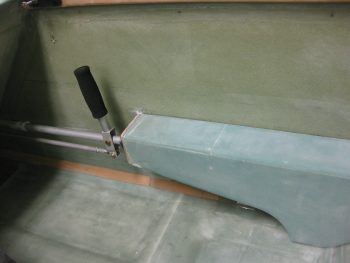
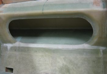
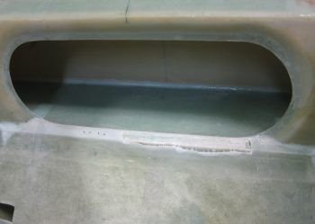
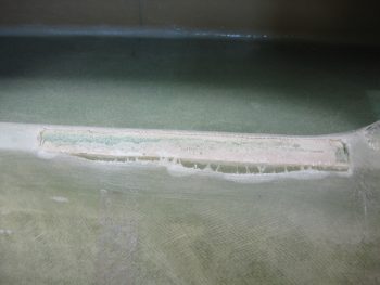
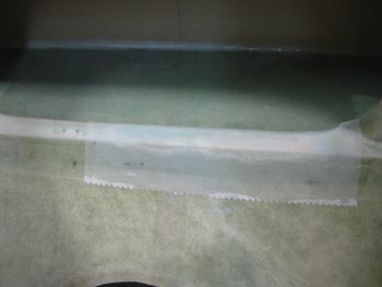
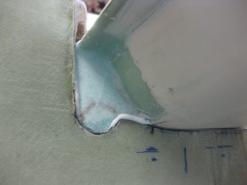
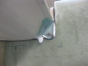
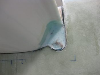
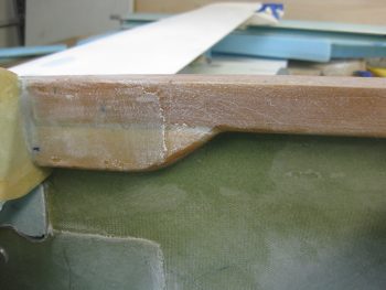
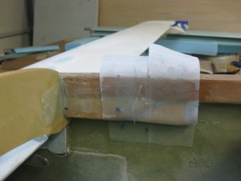
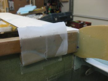
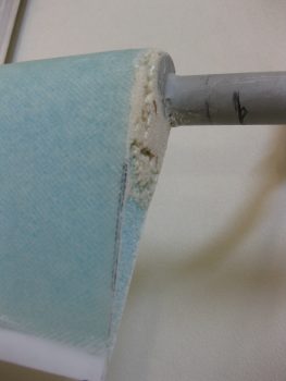
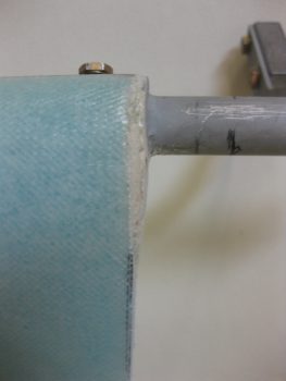
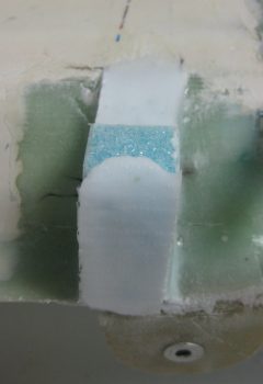
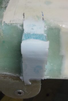
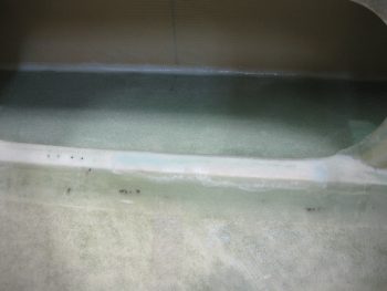
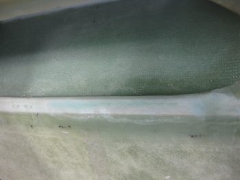
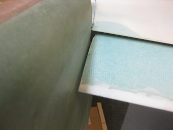
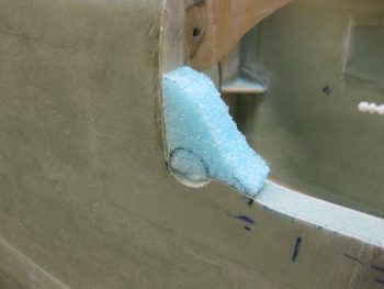
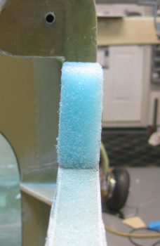
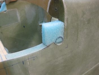
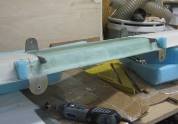
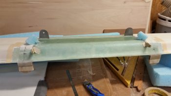
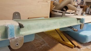
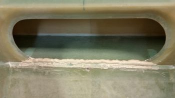
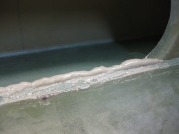
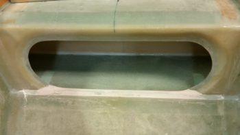
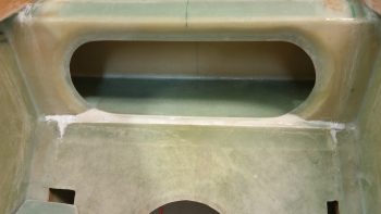
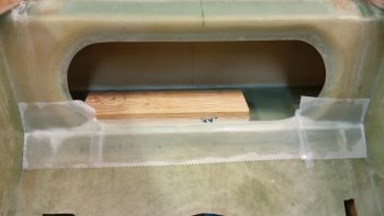
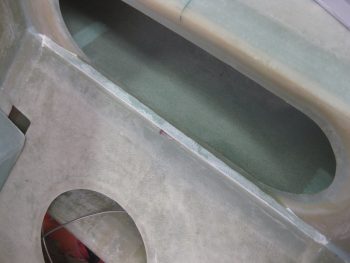
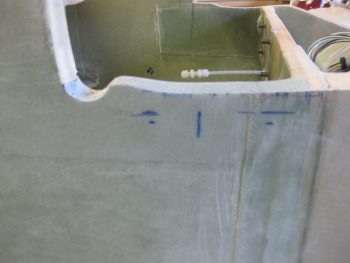
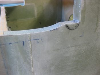
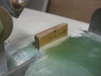
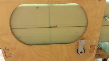
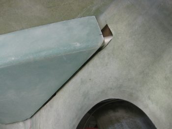
So I cleaned up the BID layups securing the 1/4″ thick Finnish Birch plywood piece that was pressed into service as the elevator control stop.  It does exactly what its official title states in that it stops the elevator from traveling more than 30° down.  Do I have an elevator up control stop?  Well, technically it’s the trailing edge (TE) of the canard, but let’s hope that I don’t use it much!

Cleaned up elevator control stop

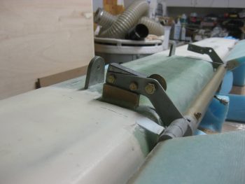
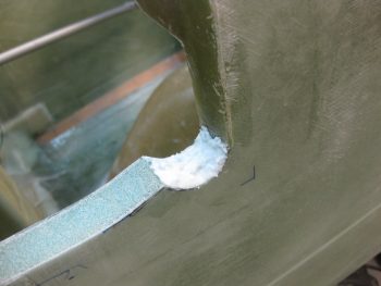
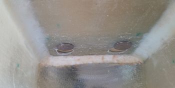
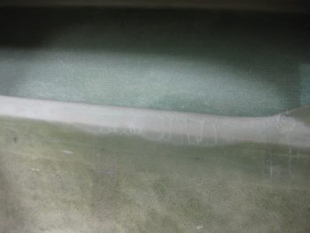
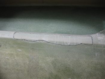
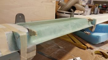
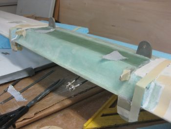
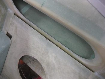
Here’s a closer view of the elevator control stop.

Cleaned up elevator control stop

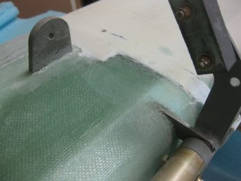
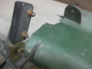
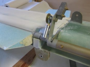
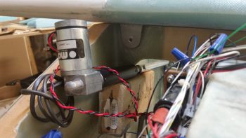
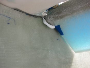
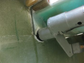
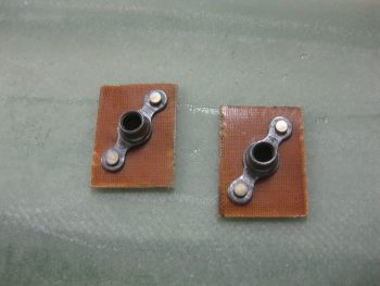
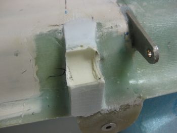
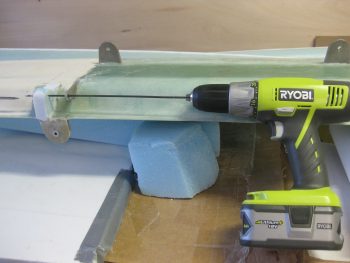
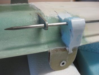
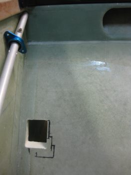
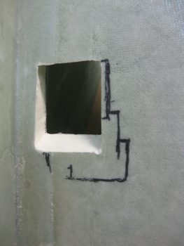
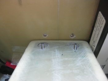
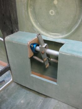
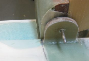
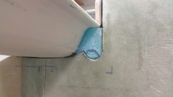
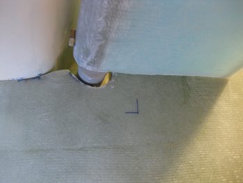
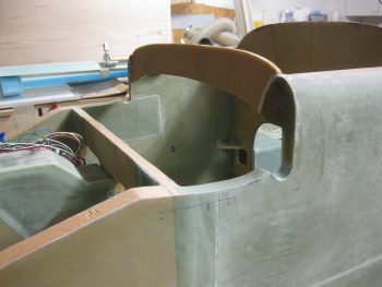
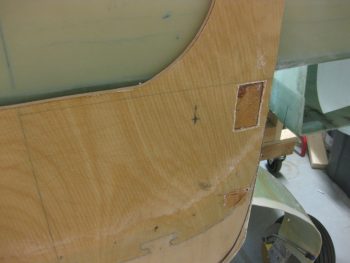
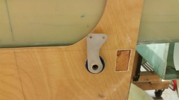
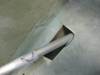
I then really started back on the control system by marking where the aileron control system bearing (CS123) gets mounted into the firewall.  The plans state W.L. 12.3 and B.L. 6.2R, so that’s what I marked up.

Marking drill point for aileron control bearing

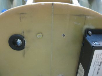
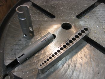
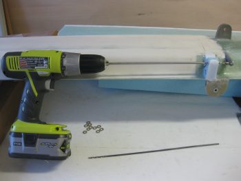
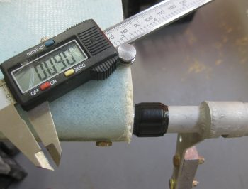
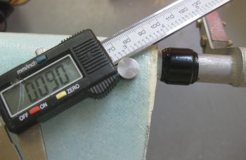
I then grabbed my German hole saw and drilled a 1.5″ hole (stock bearing is 1″, but the much nicer Cozy Girrrls bearing is 1.5″ in diameter).

Drilling aileron control bearing hole

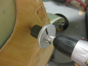
When I drilled the hole, I angled down and to the right just a bit towards the U-joint on the end of the CS116 control tube.

Aileron control bearing mounting hole

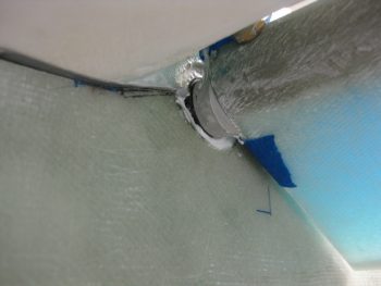
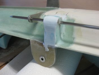
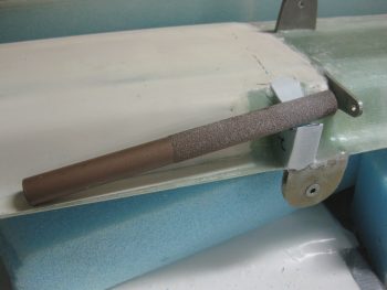
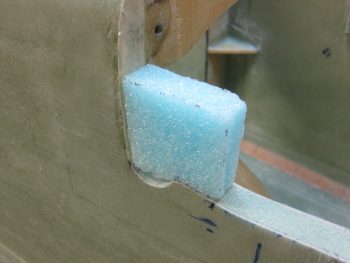
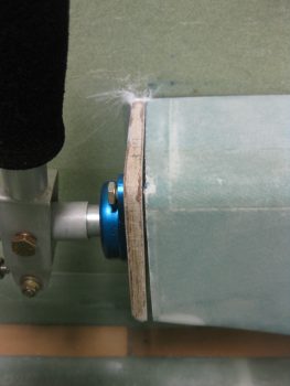
Since the hole I drilled was almost exactly 1.5″ in diameter, I had to sand the hole with the round Perm-a-grit tool.  Just a few minutes worth of sanding did the trick, and then the bearing fit perfectly.

Test fitting aileron controls

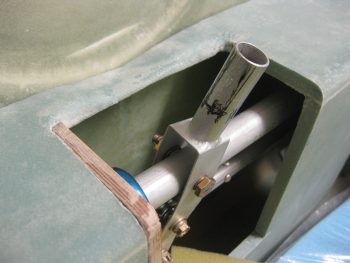
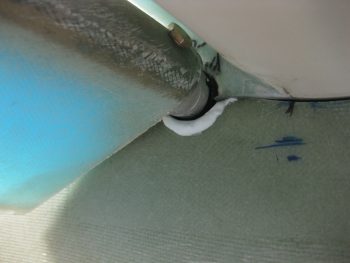
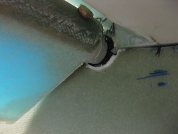
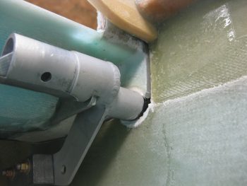
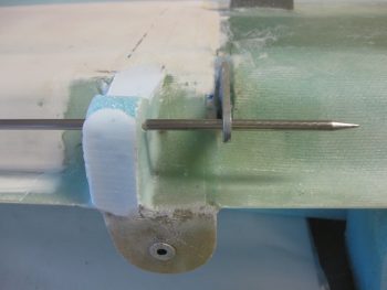
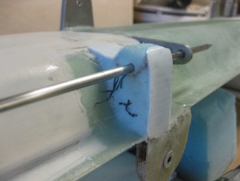
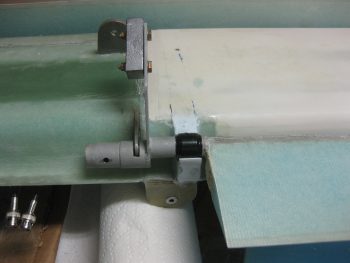
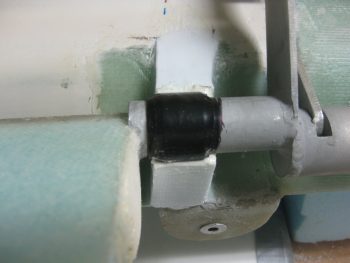
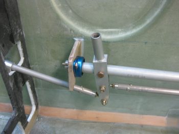
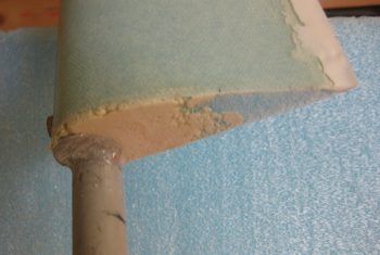
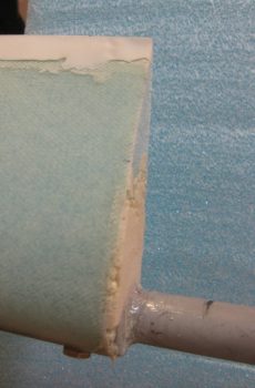
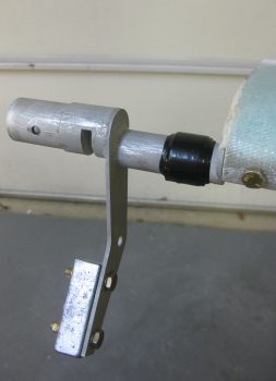
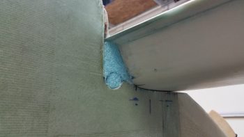
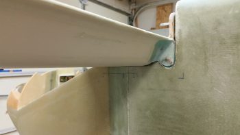
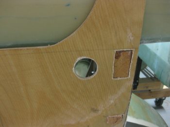
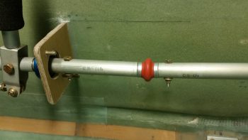
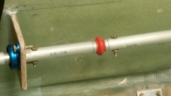
Here’s a closer view . . . both pics obviously have the CS122 control arm inserted.

Closer view, aileron control bearing

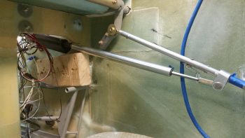
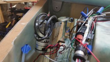
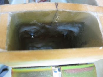
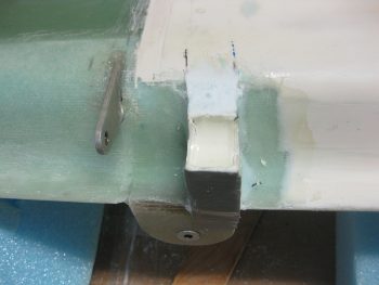
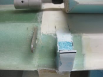
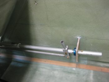
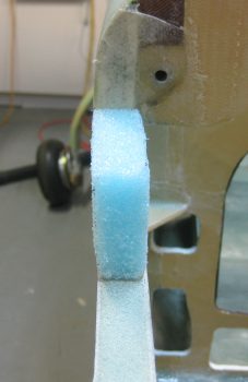
Here’s a view bore sighting down the CS122 control tube… the object at the other end is a little out of focus eh?

Peering into the looking glass . . . ?

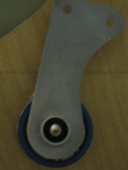
Well, let me help!  It’s the U-joint at the end of the CS116 control tube!

Target acquired, Captain!!!

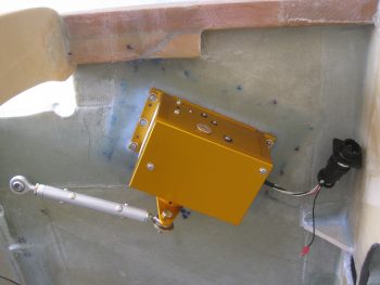
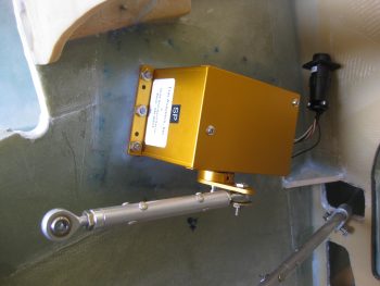
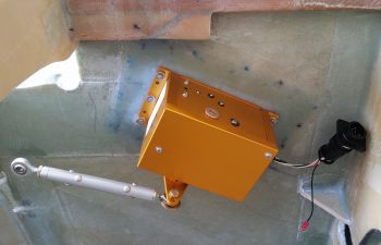
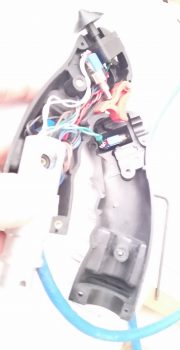
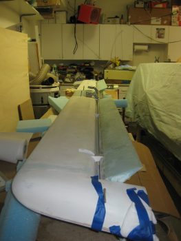
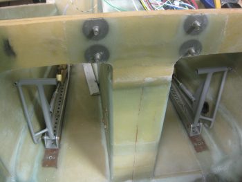
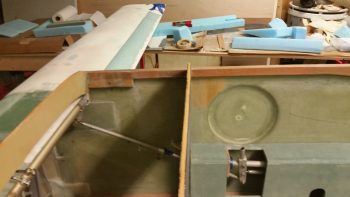
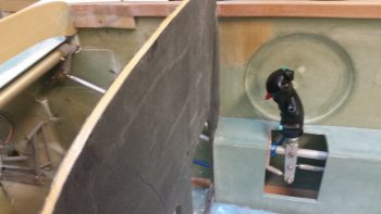
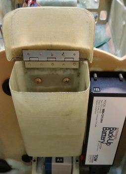
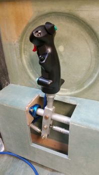
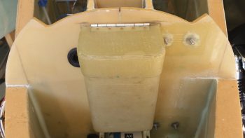
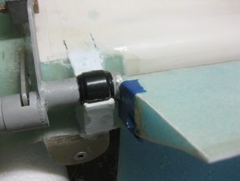
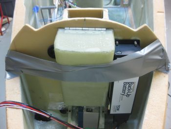
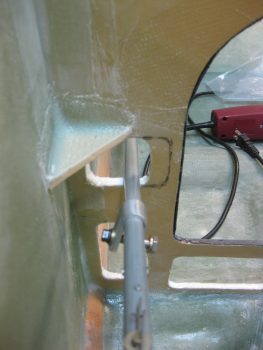
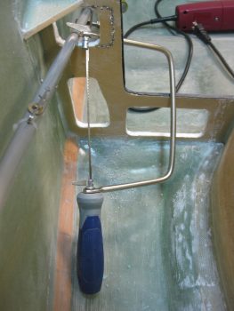
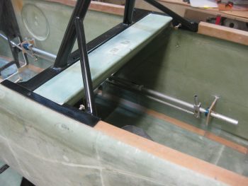
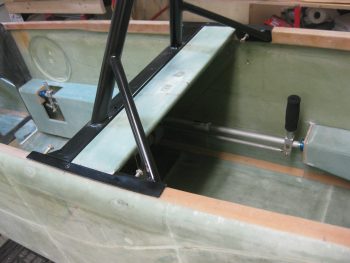
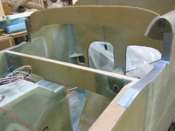
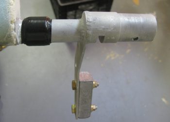
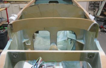
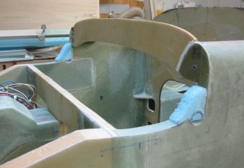
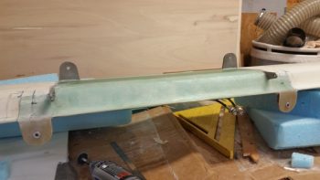
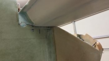
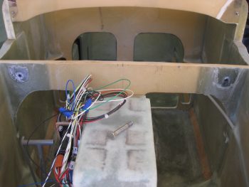
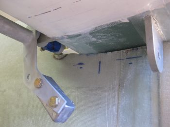
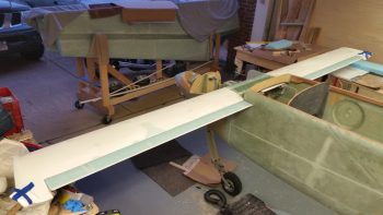
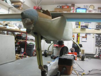
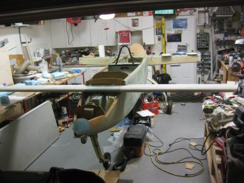
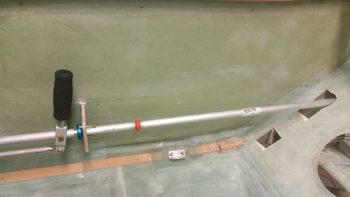
Here’s a shot of the aft cockpit flight control setup

Test fitting aileron control tube

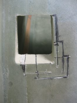
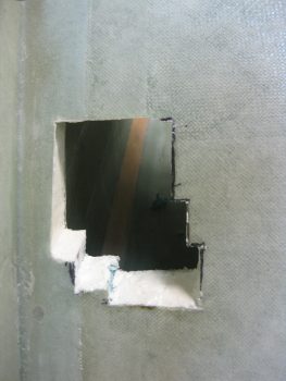
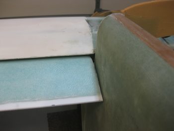
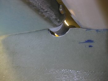
Of course there’s NO plug & play on these birds, some trimming is ALWAYS required!

Some, uh, trimming required....

OK, maybe a lot of trimming.  This is what happens when it’s required to modify the aircraft for non-standard parts (in my defense, I had no idea that this control system would need so much re-wickering of stuff.  I may have just not bought the CG’s control kit and rolled my own if I did!).

Some MAJOR trimming required!

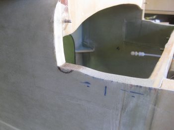
Even the arm rest’s front interface with CS118 is jacked up now!  Clearly I’m going to have to do a little bit of tap-dancing to get all this stuff to work right . . , like it did before I went that ONE next step! ha!

Ugh!

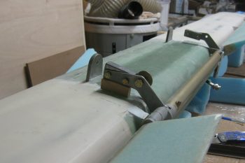
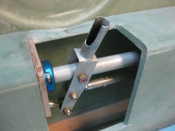
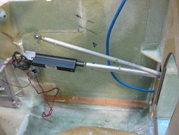
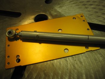
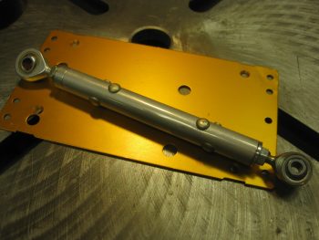
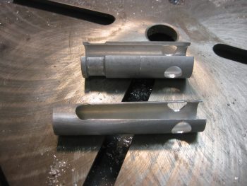
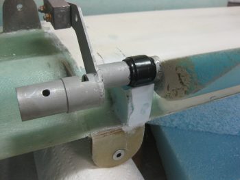
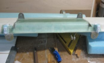
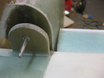
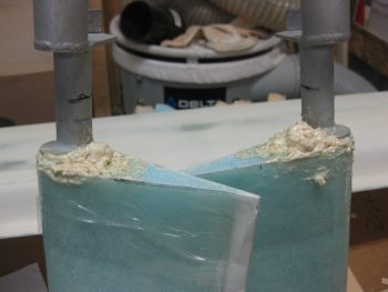
To feel like I was actually getting something accomplished, I went ahead as per plans and drilled a #12 hole through CS121 and the control U-joint (also as per plans I started with a 1/8″ pilot hole).

Drilling CS121 to U-joint

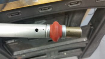
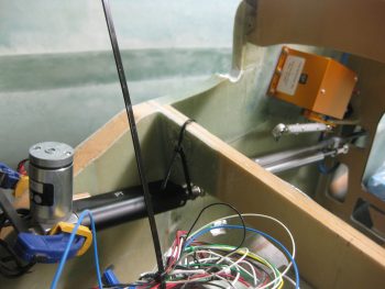
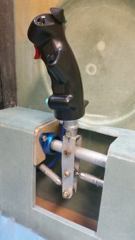
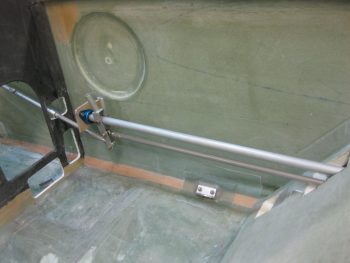
I then bolted in an AN3-11A bolt –which seems a hair long to me– and mocked up my new CS121 control tube assembly with the existing CS116 control tube.

CS121 bolted to U-joint

Here’s another view.

Another control U-joint view

Tomorrow I’ll continue to work the clearance on the right armrest.

Also, I’m having a special visitor this Monday boys & girls!  Yep, it’s Marco!!!  He’s coming here to do one of his quarterly inspections and tell me all the stuff I’m doing wrong! haha!  In all serious (but don’t blab this to him!) I’m going to try to fit in glassing in the upper engine mount extrusions this weekend so that when Marco gets here he can help me flip the fuselage and glass in the lower extrusions, then help me flip the fuselage back upright before he leaves.


Chapter 9, 13, 16 – A myriad of stuff

I started today off by peeling the peel ply off the autopilot pitch servo mounting pad & doing some minor cleanup around the edges of the layup.

I then mounted the pitch servo with the control rod in place to show what it will pretty much look like when installed operationally.

AP pitch servo mountedAP pitch servo mounted

I took the pic below with my phone and included it here because it shows the actual color much better, which is a rich yam orange vs. a sweet potato gold showing up in the pics above.

AP pitch servo installed

I had to run out and run some errands for a few hours, but when I returned home I went to work on fixing the “crease” that was running down the middle of my Infinity stick grip. Something was misaligned inside to cause a noticeable edge of one half of the stick off from the other.

The first thing I did was to “crimp” the adapter I bought from JD at Infinity to more closely encircle the adapter I made.  The second thing I did was reroute some of the internal wires that I think simply had nowhere to go so was bunching up a hair and knocking the halves just slightly askew.

Still, it was the proverbial “herding cats” game but I finally got it.  I then torqued the screws down to keep it that way, only to read a few minutes later in the instructions:  “Don’t over tighten the screws!”  . . . oh, well.  They are tight!

Infinity stick grip bracket re-install

So far the problem is solved, but I’ll have to play around with it for a while to see if it regresses before I add blue Loctite to the threads.

For those of you more esoteric types that like more pastel colors, like turquoise, I offer you this . . .   I call it, “Nouveau Grip.”

Nouveau Stick Grip

So, there I was . . . it was late afternoon, and the days are getting shorter.  Also, this warm weather spell is supposed to end tomorrow so I figured I had better get outside and do some saw work . . . er, uh, I mean some milling work!  Ok, milling work on a poor man’s milling machine, aka “a table saw.”

I bought a 2.5″ wide x 0.5″ thick bar of 2024 from ACS specifically to make my inboard mounts for the wheel pants.  I did a quick measurement of one of the inboard axle bolts & plate, then marked off the 2024 bar stock for cutting.

2024 bar stock for inboard wheel pant mounts

I stole the idea for these from Bernie Siu, who ended up with this style after 2 prior iterations of inboard wheel pant mounts, including the original style called out by Gary Hertlzer in the instructions.  These are bit more “elegant” in style, and if all plays out the way I intend, the horizontal “bar” will be able to be used to jack up the gear leg to change tires, etc.

I want to point out that these are in the ROUGH stage, since, as I mentioned before, I had to use the poor man’s milling machine to get these ginned up.

ROUGH 2024 inboard wheel pant mounts

Here’s a profile shot of the wheel pant inboard mounting brackets.  I thinned the top and bottom plate material down to 1/8″ by cutting into the 1/2″ bar 3 times, an 1/8″ at a time (for a total of a 3/8″ deep cut).

ROUGH 2024 inboard wheel pant mounts

The shot below is more to show the other 2 pieces I cut from the 2024 bar stock, and that’s a 3/8″ x 3/8″ x 1.2″ plug that will go into the end of a 1/2″ x 1/2″ 6061 square tube that I’m using as a crossbar for the GIB top seatbelt straps.  Since riding in the back of Marco’s Long-EZ, although not bad at all, I can see where there could easily be a need for folks to bring the top seatbelt straps in closer together.

My bar will be secured in 3 places: on each side with the forward engine extrusion bolt into the CS spar as the original plans upper seatbelt bracket tabs were.  And then in the middle of the bar into a hard point in the CS spar.  These 2024 square plugs will reinforce the hollow tubing for the 1/4″ AN4 bolt that will get installed vertically through each side of this bar to hold it and also, more importantly, secure the engine mount extrusion in place to the CS spar.

GIB upper seatbelt x-bar 2024 reinforcement plug

With my metal cutting tom-foolery behind me, I started working on a quasi-requirement of Trio for the autopilot.  In the manual it states to not have the autopilot act as the hard stops for the aircraft control system.  Although we don’t have hard control stops in most of our Long-EZs, I decided I would do what I could and put in a stop for full aft stick.

I had originally thought I would put a stop in both sides, under each torque tube offset arm. I may still do that, but for now I decided to just do it under the offset arm where the pressure is getting applied from the control system: the right side.  Nonetheless, when I decided this, I had already marked the area on the bottom of the canard where the finish needed to be removed to get to bare glass (below).  I did this for both left & right sides.

Finish marked for removal for control stop

Finish marked for removal for control stop

Here’s a couple shots with the finish removed, and with the glass sanded and ready for glassing.

Finish removed for control stop

Finish removed for control stop

Here’s a long view with the elevator control hard stop in place.  The elevators are set at just a skooch over 30° at about 30.5°, just to make sure the full operational limit is obtained.

In addition to Trio’s requirements (which apparently I’m meeting only 25% of!  …. actually, I talked to Chuck Busch and he said all was good with my install plan!), I found an old CP (CP# 48 pg 4) that stated some canard pilots were having issues rotating if they pulled full aft stick and the elevators went past 30° down.  This gets into the backside of the lift curve and interestingly may not get the nose of the plane off the ground.  As per the CP, in this scenario one would be “on the “back side” of the lift curve, lift is less than maximum and the elevator is creating lots of drag.” Marco was having some of these same type of issues on his plane, and found that NOT going full aft stick on takeoff was giving him better liftoff.  Of course I’ll test it out and adjust the stop as necessary IAW this CP.

Testing control stop depth

Here’s a closer shot of the elevator control stop.

Testing control stop depth

I then floxed the elevator control stop in place, made some flox fillets and glassed each side with 1 ply of BID initially.  Then, since I had enough epoxy, I added one more ply of BID to the inboard side since my first NON-prepregged piece of BID decided to go just a tiny bit wonky on me.  I then peel plied the glass intersection on the canard surface.

Elevator control stop floxed and glassedElevator control stop floxed and glassedElevator control stop floxed and glassed

Later in the evening, I reinstalled the Infinity stick grip in the arm rest and tested it out.  Alles ist gut!  . . . so far.

I realized the other night that my initial estimations on where the rudder pedals needed to be mounted were way off!  I guess I’m just a lot taller than I remember (ha!) because twice I had to remount the rudder pedals farther forward.  In addition, the space in the nose is TIGHT, and I may have to lop off the inboard tubes that make up the “T” on the rudder pedals.  Currently, it’s just too difficult to set my feet along side them as if I were in the relaxed cross country mode, then bring my feet back onto the pedals.  My shoes snag on that top pedal crossbar and make it a real hassle to get my feet back on the pedal.  Since it’s so narrow on each side anyway, I doubt if lopping off that extra metal tubing will affect my ability to mash these pedals when needed!

Adjusting rudder pedal positions

With a really good idea of my pedal geometry now, I decided to re-attack the placement of the Atkinson pitch trim assembly.  After mocking it up in different spots for a bit, I pretty much concluded that it has to go where I had planned for it to, except with one minor modification: it most likely will have to be mounted at an angle with the actuator motor leaning from 30-45° inboard to clear the upper curvature of the nose.

Test fitting pitch trim assembly again

Tomorrow I have to get some work done on my truck, then run some more errands.  I plan on finalizing some more of this perpetual odd-n-end stuff and hopefully move onto doing stuff that’s actually covered in the plans!


Chapter 16/17/22 – AP Pitch Servo

Today was all about getting the Trio Pro Pilot Autopilot pitch servo mounting bracket glassed in place on the right fuselage side wall.  Since I prepped everything last night, it allowed me to just jump into the fray this morning.

I started by cleaning off the Clickbonds with Acetone & then adding a dab of 5-min glue to the bottom of each one.  I had them in place in the mounting bracket to allow me to align the Clickbonds to the actual pitch servo bottom mounting plate when I glue them to the sidewall.

5-min glue on Clickbonds

I then lined up the whole assembly and pressed the Clickbonds into place onto the fuselage sidewall.  I held it there by hand for about 3 minutes to ensure the 5-minute glue set up.  I kept the bottom edge of the mounting bracket aligned with my angled alignment mark that I had made on the side wall, and my left-right alignment was my arrow on the lower left corner of the mounting bracket that aligns with the intersection of the slanted alignment mark and a point 7-3/4″ aft of F22.

Mounting Clickbonds- mounting plate template

After a few more minutes I pulled off the mounting bracket from the Clickbonds, and after a few double-checks on their alignment, let them cure.  The middle dark area just to the right of the left row of Clickbonds is actually a 2-ply BID layup I threw on the side wall to help fill in the elevation gap between the uber 4-ply BID that secures F22, and the sidewall just aft of all that thick BID pad [not a big deal, but perhaps the install could have been better engineered by the Trio gang to avoid this 4-ply BID pad-to-sidewall transition area?….still, no big worries].

Clickbonds mounted in place

As the Clickbonds cured I whipped up some epoxy and wet out the prepregged 3 plies of BID.  I then used the mounting bracket to mark the BID to allow me to cut small holes in it for the 6 Clickbond access holes.

Marking mounting holes on prepreg

I then whipped up some flox and applied it around each Clickbond base and in the transition area to provide a straight foundation for the mounting bracket.

Flox fill for irregular sidewall surface

I then laid up the prepregged 3 plies of BID.  While the prepreg plastic was still on, I taped up the bottom of the pitch servo for anti-gunk protection and used the actual servo to press in on the flox to attain the exact amount of flox angle required for the servo to sit flat against the sidewall.

3-ply BID prepreg laid up

I then pulled the peel ply top plastic, applied a bunch more flox and then set the mounting bracket into place.  I then laid up the 2-ply BID prepreg over the mounting bracket. Again, with the prepreg plastic still on, I once more set the actual servo on the Clickbonds and applied firm pressure to set the mounting bracket, flox and BID plies into place.

Mounting bracket floxed in with 2-plies BID

I then pulled the prepreg plastic and peel plied the entire layup.

Peel plied AP pitch servo mount bracket layup

Today was a short work day since I helped an Air Force buddy that just arrived into the area move some furniture.  Tomorrow I’ll pull the peel ply and clean up this layup.  Then I’ll mount the pitch servo.  I also need to reset the mounting bracket inside the Infinity stick grip because the plastic handle halves are misaligned just a bit, and it’s creating a ridge down the center of the grip stick that will annoy the snot out of me if I have to fly with it! With that, I’ll continue to work the main fuselage/cockpit flight controls as much as possible until I can’t continue (i.e. no firewall aft controls) and I expect to be getting back to the wheel pants next week.

Chapter 16 – Getting a Grip!

I started off today by spending a good 45 minutes mounting the elevators to the canard. The hinge pins went in significantly easier than they have in the past, but I still have to flip the canard right side up to get the pin tips to natural hang point down inside the elevator tubes to get get them through the middle hinge pin bracket.

After getting the elevators mounted, I then gathered up the hardware & attached the elevator push rod end to the outboard side of the right torque tube offset arm.

E,levator control tube coupler

With the canard & elevators remounted, I then clamped the outboard ends of the elevator to the outboard ends of the canard to set the elevator at 0°.  I know that the elevator is positioned just a bit lower than this during cruise flight and I would intuitively think that the control stick position would correlate with the cruise position, but since nothing is referenced in the Roncz canard plans I went with the original Chapter 11 plan’s “neutral elevator” position… although I guess that could be interpreted a few different ways. Nonetheless, I called this 0° neutral and rigged the elevator control push tube accordingly.

[A side note: for some reason my elevators are about 3/16″ off between the two sides at the outboard tip.  I’ll use the hot weather trick when the weather gets hot again next year to straighten them out.  Not sure why they’re off, perhaps they settled in differently during storage].

Setting elevator to 0 degree positionSetting elevator to 0 degree position

With the elevators pinned at 0°, I then set the control stick positioned 5° forward as per plans.  I then marked the CS136 control tube, cut it and then drilled & riveted the rod end into place.  I then mounted the elevator push tube to make my first officially moving control surface!

Here is the elevator with the control stick at neutral.

Rigging elevator controls - Neutral

And again with the control stick full aft.

Rigging elevator controls - aft stick

And the stick full forward.

Rigging elevator controls - fwd stick

With the elevator rigging completed, I then turned to finalizing the installation of my Infinity stick grip.  To make clearance for the decent-sized cable exiting the bottom front of the Infinity stick grip, I needed to mirror the cable channel on the stick grip adapter onto the CS103 control stick tube.  I sat in the pilot’s seat and set the stick so it was “clocked” correctly for my hand in a natural position.  I then marked the intersection of the Infinity stick grip adapter and CS103.  I then removed the stick grip and finished marking the channel that would need to be cut into CS103.

Notching pilot control stick assy for grip cable

Since I haven’t been able to repair my downed Dremel Tool yet, I bought a cheap HF rotary tool for less than $20 and used that to cut the channel in my CS103 control stick.   I left 0.8 of full tubing on the bottom of CS103 for strength and to have an area to drill & mount an AN3 bolt which will secure the Infinity stick grip.

Pilot control stick assy notched for grip cable

Then, just to make sure I got it right, I climbed back into the seat and did one final clocking of the control stick position.  I marked this final position at the base of the stick . . .

"Clocking" control stick yaw for comfort

and then drilled the base to accept an AN3 bolt.  I then attached the bolt & Voila! My front Infinity control stick grip is officially mounted!

Stick grip mounted

Here’s a better shot.

Stick grip mounted

With the elevator controls rigged & my stick grip mounted, I then spent a few minutes getting a feel for how the Atkinson pitch trim assembly was going to get mounted into place.  As you can see, I wedged the pitch trim assembly up into place using a 2×4 resting on the rudder pedal.

Atkinson pitch trim test fit

Here’s a shot from the front of the plane.

Atkinson pitch trim test fit

Here’s another shot with the actuator motor turned facing down, which may be required for clearance for the top of the nose.  I also need to set my rudder pedals in their final position and check that my right foot has clearance with the pitch trim assembly.

Atkinson pitch trim test fit

After I removed the canard, I tested moving the pitch trim assembly aft into the area between F22 & the IP.  Although my foot could be very close to the actuator assembly (what isn’t a tight fit in a Long-EZ???) this may just be a viable mounting position.

Assessing mounting options for pitch trim assy

Done with my pitch trim test-fitting shenanigans, I then moved forward with preparations for mounting the Trio autopilot pitch servo.  Since I’m messing with the elevator control system, I figured now was a good time to knock out installing the AP pitch servo mounting.

If you remember back a few months ago, I had to send my pitch servo back to Trio to have them install the auto trim option.  In transit back to Trio the Postal Service decided to drop kick this sucker… enough so that even buried in inches of bubble wrap they managed to ding a corner of the mounting baseplate.  Well, most things work out for a good reason in the end, and this was one of those.  Chuck at Trio sent me the dinged mount back with the upgraded pitch servo.  I figured it was a novelty item until it came to actually mount the pitch servo.  After digging into the installation manual & documentation, I realized this dinged baseplate will serve as a perfect mounting base for my pitch servo install!

Damaged Trio pitch servo mount plate

Although a bit out of order from the installation instruction sheet I got from Chuck, I cheated a bit using Nick Ugolini’s documented install instructions and went ahead with cutting the pitch servo pushrod to length (4.05″).

Trimming pitch servo control tube to length

I then mounted an HM4 rod end on the freshly cut end (elevator side) using 1/8″ rivets.

Pitch servo control tube made to length

Then, to lighten an already light pitch servo mounting base, I made Swiss cheese of the previously dinged up base.  More importantly, these holes are to allow flox to ooze through and better secure the mounting base.  A final important note is that you can see that a compelling reason to use the dinged up mounting base is that it already has holes that align perfectly to the actual pitch servo base mount.  I called Chuck earlier to confirm that it was ok to drill the out these mounting holes to accept a 10-32 bolt, thus allowing me to use Clickbonds to secure the pitch servo in place.  Also, since the AP servos are sensitive to twist & minute movements that can cause slight errors in AP track functions, I’m using 3 Clickbonds per side to ensure the pitch servo is mounted securely and as little twisting action as possible is allowed during operation.

Damaged mounting plate used for mounting base

I then sanded the area on the right sidewall in prep for mounting the AP pitch servo.

Right fuselage sidewall prepped for pitch servo mount BID

My last task of the evening was cutting 5 plies of BID for mounting the AP pitch servo.  All the plies allow for 1″ overlap around the AP base mount, so they measure 5″ x 8″.  The layup schedule for these will consist of the Clickbonds getting floxed into place, 3 plies of BID over the Clickbons, the base plate with liberal amounts of flox and then finally 2 plies of BID on top.

5 plies BID for Trio AP pitch servo mounting

Tomorrow I’ll layup the glass for the AP pitch servo mount, and continue to work on the control system.  In fact, I really just need to mount the aft cockpit-to-firewall control components and I’ll be finished with Chapter 16, so I’ll knock that out before moving back onto the wheel pants install.


Chapters 11/12 – Canard & elevator wrap-up tasks

Well, hopefully really wrap-up tasks, as in “the end”!

Today I knocked out the main tasks for denying unwanted cold air to enter the fuselage via the elevator control tube transition into the fuselage.  As you’ve probably seen, I filled in the gap immediately behind & under the canard with the Cozy plan’s “filler piece” and then filled in the area immediately around the torque tube offset with micro/flocro–both on the fuselage and canard “filler piece” sides.  Well, that’s what I finished today, so read on dear reader . . . read on!

I started off today by test fitting the canard, with the elevator torque tubes still taped up with electrical tape approximately 0.090″ thick, to the fuselage/nose.  After I ensured it fit, I took it off, flipped it upside down and trimmed up some of the micro on the canard side.  I also lightly coated JUST the electrical tape with WD40 as a release agent so that I wasn’t taking an unintended action of permanently gluing my canard to the fuselage!

Prepping for fuse;age side micro

I then whipped up micro (actually flocro) using fast hardener and put it into the areas on the fuselage where the elevator control tubes (torque tube offset) transition the fuselage sidewalls.

Micro applied to torque tube offset transition

Here’s a closeup of the left side immediately prior to me setting the canard in place.

Micro applied to torque tube offset transition

And this is the left side immediately after I set the canard in place.  Note the flocro oozing out of the seam.  You can see the same for the right side below.

Micro applied to torque tube offset transition

Micro applied to torque tube offset transition

I then cleaned up the excess flocro from both the left and right sides.

Torque tube offset transition Left outbdTorque tube offset transition Right outbd

And here’s a couple shots of the inboard torque tube transition points.

Torque tube offset transition Left InbdTorque tube offset transition Right inbd

With the flocro curing on the mounted canard, I decided to knock out the mounting of the nose tool box.  I drilled two #10 mounting holes through the upper tool box mounting hardpoint.  I had to ensure to drill the holes inboard just a bit more than I had originally planned to make sure the nutplate assemblies could be mounted properly on the aft side of the Napster bulkhead.

Tool Box upper mounting holes drilled

Here’s a shot of all 4 tool box mounting holes.

Tool Box mounting holes

I then made up a couple of K1000-3 nutplate assemblies using 1/16″ phenolic as a base.

Tool box phenolic nutplate assemblies

I then mounted the tool box on the lower mounting tabs, finalized its position, and marked the upper mounting hole positions using a scribe.  Then I drilled the mounting holes through Napster using a #10 bit.

Mounting holes drilled in Napster

I floxed the nutplate assemblies in place using two AN3 bolts to hold them in position.  Then I added a ply of BID over each nutplate assembly.

Tool Box nutplates floxed/glassed on Napster

The pic below is actually the last shot I took this evening, but I’m putting it here for a better topic flow.  So… here it is.  My tool box is officially mounted!  I included the IBBS in the pic to show how tight the quarters are in the nose, but so far it all fits.

Nose tool box mounted

I sort of did a repeat of last night, only now with both the canard and tool box composite stuff curing, I set my sites on making an adapter for the Infinity Stick Grip.  Technically, I’m making an adapter for the adapter since JD makes these adapters for 3/4″ OD tubes.  The tubing on the top of the Cozy Girrrls’ control assembly is 5/8″ (plans dimension), so another adapter is required to get the Infinity stick grip mounted onto the control stick assembly.

As with many things on this build, in prep for these steps over the last few days I had to Google some of this stuff.  I got the specific information on how this adapter is made from a forum post from Bernie Siu.  I can’t find it just now, and I tried going to his website, but it is out there.

I first took the plans identified 5.2″ piece of 3/4″x0.58″ walled 6061T6 aluminum tubing and cut it down so only 0.6″ hung out the bottom of the Infinity Aerospace adapter (standing on end in the pic below)… making the overall length of my new adapter about 2.75″.

Making Infinity Stick Grip adapter tube

Then, as per JD’s instructions, I drilled a 29/64″ hole all the way through the new adapter to match the 29/64″ hole in the Infinity adapter.  I then drilled two more 29/64″ holes perpendicular to the first set of holes & only on one side of the tube.  I then essentially connected those holes to make a wide slot down the center of the tube.  This slot allows the multi-wired stick grip cable to transition through these adapters.  Unfortunately, my Dremel tool died so I had to cut the entire slot sides by hand!

Making Infinity Stick Grip adapter tube

I needed 8 hands to keep the innards of the control stick from flying out everywhere when I mounted the adapters inside the stick, so unfortunately I didn’t get any pics of that insane process.  As you may be able to tell below, the stock adapter slides around the adapter that I made this afternoon, which in turn slides onto the control stick assembly.

Below you can see that the control stick grip is just too high.  I have to cut that same size channel into the bottom control stick assembly in order to get the cable out of the control stick without pinching it.  That should let me get the correct stick height dialed in.  In addition, I’l have to sit inside the front seat and test out the control stick in order to “clock it” correctly to know exactly where the front of the stick will face.  This will determine precisely where I need to cut the channel in the bottom control stick assembly.

Pilot control stick

After all my control stick adapter shenanigans, my flocro was pretty much cured so I popped the canard off the fuselage and found this . . .

Cured micro for elevator torque tube offset

and this.  Not too shabby if I say so myself.  And moreover, I say: “Goodbye cold air!”

Cured micro for elevator torque tube offset

Below is the canard side after I pulled the electrical tape off the elevators.  You can see the micro did a great job on this side as well.  It all still needs to be cleaned up & tweaked, but I’m glad this is starting to wrap up (a slight pun).

Cured micro for elevator torque tube offsetCured micro for elevator torque tube offset

Next I’ll mount the elevators full board with the center spool tube and all.  Then I plan on configuring the control system for pitch and linking up the elevator control rod to the main control system.  I’ll also try to repair my Dremel Tool so I cut that channel in the control stick and get the Infinity stick grip mounted as well..


Chapter 23 – Early Christmas!

After a late night building last night, today I was awoken by the FedEx guy delivering my Hertzler Silver Bullet Prop!  Yeah, one more major item off the list.  Getting much closer to getting this baby in the air!

Silver Bullet Prop Arrives!Silver Bullet Prop

After gawking at the prop for a while, I then went down to the shop and removed the tool box from its lower mounts.  To do so, I removed all the tape from the inside of the tool box that had kept the Clickbonds in place, and then I very slowly worked the box back & forth to free it from some of the cured flox. After wiggling it back and forth with a very slight prying action it popped free after about 20 seconds.

Tool box lower mounts installed

I then removed the protective packing tape from the back side of the tool box, and cleaned up the holes just a bit.  Then I remounted the tool box to see how it fit.  Ahh, nice & tight against the Clickbonds that were pressed into service as mounting tabs!

Tool box lower mounts installed

The fit is so tight the tool box stays in place mounted onto jus the lower tabs, even when I open & close the lid.  Obviously once I get the upper 2 button head screws drilled & mounted it will be nice & secure.  I’m extremely pleased thus far on the way this tool box is working out!

Tool box lower mounts installed

As I said yesterday, today is a light build day since I’m taking the night off for social frivolities. Tomorrow first thing I plan on filling flocro in on the fuselage side of the elevator torque tube assemblies, which will make up the lower half of the holes for the elevator control tubes traversing the fuselage/nose sidewall… thus minimizing the amount of unwanted COLD air entering into the cockpit.


Chapter 11/16 – Just doin’ it!

First thing today I checked the layups on my longeron doubler extensions.  I pulled the peel ply and cleaned them up a bit.

Right longeron doubler extension

The left side looked good as well.  The extension piece may look like it’s drooping a bit on the aft side, but this is due to my wanting a bit more wood to drill into since my 3/16″ upper alignment pin hole angles down slightly.

Left longeron doubler extension

Well, as you can see here!

Left longeron doubler & extension drilled

And it angles even more so on the right side (which I didn’t think it did) so I should have angled the extension piece just a tad more… oh well, it will definitely work.

Right longeron doubler & extension drilled

I then started work on shaping the canard filler pieces to “wrap” around the elevator torque tube offsets.  To get a good idea of the alignment, I started by drilling a 1/8″ hole through the inboard hinge bracket, through the filler piece at nearly the exact spot the hinge pin would pass through.

Drilling canard filler piece

I then hopped over to the outboard side and drilled a #10 hole through the filler piece using the 1/8″ hole as a pilot hole.

Drilling canard filler piece

I then simply pressed the hinge pin through with Eze.

Canard filler piece alignment

Canard filler piece alignment

I then repeated the same process on the right side (which is the left side of the canard).

Canard filler piece alignmentCanard filler piece alignment

With a known center point on each filler piece, I then carved out a circular area around it as a starting point for fitting in the torque tube offset.

Prepping filler piece for torque tube offset

I then started the cycle of test fitting the tape-wrapped torque tube offset into the filler piece.  I would cut and sand some of the filler piece material off, then test the torque tube offset.  Repeat.

Prepping filler piece for torque tube offset

Here’s the first round, with the black mark showing more filler piece material that required extrication.

Prepping filler piece for torque tube offset

After a few cycles I got so that there was a very small gap around the tape-covered torque tube (which is exactly what the tape is for).

Filler piece & torque tube offset ready for micro

With a better idea of exactly how much material required removal from the left side, my first material-removing step out of the gate on the right-side canard was much more substantial.

Cutting right side filler piece for torque tube offset

Of course it still took a few cycles to get it dialed in.

Prepping filler piece for torque tube offset

Using my trusty round Perm-a-grit sanding tool along the way (still love these things!!).

Sanding right side filler piece for torque tube offset

And Voila!  Fini!

Filler piece & torque tube offset ready for micro

I then dug out the foam on both filler pieces in prep for some Flocro.

Canard filler piece ready for microCanard filler piece ready for micro

Since this is simply filler material to block air, I used my OLD MGS 335 epoxy that I bought years ago and whipped up some Flocro.  I applied it liberally into the freshly dug troughs in the filler pieces.

Canard filler piece micro'd

Canard filler piece micro'd

And then mounted both elevators in place.

Taped torque tube offset set in place in micro

Of course I had to scrape a lot of excess Flocro that oozed out, but afterwards it all looked nice & tidy.  I then left the elevators, filler pieces & canard alone to let the Flocro cure.

Taped torque tube offset set in place in micro

My next task was to widen the hole in the pilot’s seat where the flight controls transition through.  Due to my use of the Cozy Girrrl control sticks, and my subsequent remounting of CS109 & CS118 control mounts –to kick the control tubes 3/4″ inboard– I now have to deal with 2nd order affects in that the control tube transition hole in the front seat is too narrow.  To be fair, it was nearly too narrow from day 1, no matter how I configured the controls.

Regardless, it was time to enlarge the hole in the front seat.

Enlarging control system hole in front seat

As you can see, I marked it off using a very scientific method called “eyeballing it”.  I will state that my initial crazy pattern here is not my own, but one I plagiarized from my build buddy Dave B.  So if it looks weird, blame him!  ha!  (Love ya Man!)

Enlarging control system hole in front seat

I then used my Fein saw and a hack saw blade to make the initial cuts.

Enlarging control system hole in front seat

I had originally planned on working on my control system at this point, but since I had whipped up so much flocro for the canard filler pieces, I went ahead and dug out a small trough of seat foam along the sides of the freshly cut extended hole areas and filled in the edges with the flocro.

Enlarging control system hole in front seat

So, with two separate flocro-curing tasks in the “awaiting cure” stage, I had to make myself useful in the shop.  I decided to have a little fun and work on mounting my tool box in the nose battery compartment.

Testing nose tool box fit

I had originally planned on using button head screws in four (4) places to mount the tool box to the front of the Napster bulkhead.  As I pondered the mounting though, I just didn’t want have to deal with “wasting” two K1000-3 nutplates for the bottom mounts… nor did I want to have to try to work at the bottom of the narrow channel immediately behind Napster (made up of the 2 NG30 “goal post” arms).

Since the bottom attach points for the tool box don’t need to be screwed in or out to mount the tool box, and will be essentially forever stagnant in purpose, I decided to simply use Clickbonds as my attach points and even more simply just flox them in place into holes drilled into Napster.  Now, the top two button head mounting screws will get K1000-3 nut plates and will be removable.

With my plan devised, I moved forward to set it in motion.  I marked off the perimeter of the Clickbonds on the aft lower side of the tool box.  I then drilled out the holes so that the Clickbonds could slide into the interior of the tool box.  I then took a small drill bit and made notches for each actual Clickbond threaded shaft (albeit not as straight as I wanted them!)… as symbolized by the small black dot looking things at the top of the circles in the pics below.

Drilling tool box lower mountsDrilling tool box lower mounts

I then placed packing tape on the back side of the tool box to protect it from wayward flox. I also taped the Clickbonds into their respective notches using duct tape on the inside of the tool box.

I sprayed black spray paint onto a stick and while wet applied it to the tips of the Clickbonds.  I then carefully & gently lined up the tool box into its final mounting spot and pressed the lower tool box –and the Clickbonds– against the face of Napster.  I then had 2 marks to identify my drilling points.  I used the long 1/4″ drill bit to make my initial holes, but at an angle since space is tight in the nose.  I then cleaned up & straightened the holes using another bit, by hand.

Floxing tool box lower mounts to Napster

I then whipped up some flox and filled in the 2 drilled mounting holes.  I also slathered some onto each Clickbond and set the tool box in place.  I taped it in place with duct tape and let it alone to cure.

Tool box secured while lower mount holes cure

With 3 separate build parts all in the curing stage, I decided to prep the foam for the fuselage side of the torque tube offsets, where it too will get some flocro.  When this flocro goes in, it will finalize the other half of the elevator torque tube mounting hole –of course the elevators with their taped-up torque tube offsets, as well as the canard, will have to mounted for this flocro to be shaped correctly.

Nonetheless, it gave me something to do for 5 minutes.

Prepping fuselage torque tube offset transit for microPrepping fuselage torque tube offset transit for micro

By this point, the flocro was slightly cured, so I covered the bottom of the pilot seat back control tube hole with packing tape and pressed on with the flight control system test fitting.

I quickly realized yet another 2nd/3rd/whatever order affect from moving the control tube inboard 3/4″, and that was now the hole in the Instrument Panel bulkhead was too narrow for the control tube that goes forward & links to the elevator torque tube.  Thus, I marked it for cutting as well.

Elevator control tube hole needs enlarging

Since this is really tough foam, I drilled small holes along the cut line.  I then disassembled my coping saw and put it back together with the blade on the inside of the hole that needed to be opened up.

[I opened up the hole, but apparently forgot to take any pics of it.  But you can see the widened hole to a degree in the pics of the control system below.]

Enlarging elevator control tube hole in IP

I then mounted pretty much all of the flight control system in the cockpit.

Testing out flight control system

Here’s the aft (GIB) control stick.

Testing out flight control system

And the pilot’s control stick.

Testing out flight control system

A close up of the pilot’s control stick assembly.

Testing out flight control system

I then set the arm rest consoles in place.  Both the front seat . . .

Testing out flight control system

and the back seat.  Of course I had to throw on the actual control stick grip as well!

Testing out flight control system

Testing out flight control system

And, with multiple items in the curing stage, here’s the grand finale shot of the evening!

Testing out flight control system

Tomorrow will be a fairly light build day since I’m heading out tomorrow afternoon to have dinner with friends.  I’ll check on & clean up today’s tasks…  and I need to do some research on the control system as well.  But I’ll back on the build full tilt on Saturday.


Chapter 11/12 – Two steps forward…

Ahh, and the proverbial one step back!  Although I only got about 5 hours of sleep today, strange things were afoot in the shop as I slumbered.  The last thing I did before going to bed was I checked this layup, and it looked it great.  It was a bit chilly last night so I left a heat lamp on the layup so as not to have to turn on the heat in the garage for a layup that was essentially cured (or so I thought).

Wanting to check out my masterpiece this morning I was of course taken aback when I saw a HUGE delam bubble running down the face of it.  Wow!  The only thing I can guess is that perhaps the pour foam was still off-gassing just a tad and over the hours it created a bubble.  Or maybe I just need to stop my shenanigans of combining heat lamps with fast hardener… might be just a bit too much for these layups to handle.  I’m going to try a mini experiment with that and not use heat lamps on fast hardener layups for a while and see if there’s a difference.

GIB seat/CS spar junction layup

Ok, so here’s this hideous monstrosity of a delam . . .  Boo!  Hiss!  Argh!

GIB seat/spar layup delam!

It was a few hours before I got around to working on it, or even taking these pics and I swear it GREW!  Stand back folks, this ain’t your garden variety delam… this here is a Mojamma delam, and it requires extrication!  So I marked off the area for surgery.

GIB seat/spar delam marked

And cut it out with my Fein saw….

GIB seat/spar delam cut out

This is what a close view of sheer disgust looks like!

GIB seat/spar delam cut out

So of course I had to cover it up… with 1-ply of BID of course.  That’s after sanding it and floxing the transitions.  I also injected a couple of smaller bubbles with pure epoxy off to the left (in the pic) of this delam,..where you may note the vampire bite marks.

GIB seat/spar delam re-glassed

With the freak show out of the way, I then turned my sights on getting the canard install much further along.  I taped up the edges of the canard “shelf” on the fuselage sides to protect it from micro.

Protective tape on fuselage sidewalls

I then whipped up thick micro and slathered the edges of each canard filler piece on the canard . . .(always gotta have at least one blurry pic!)

Micro on canard filler pieces

. . . and then mounted the canard on the fuselage.  As you can see with the right side below, the taped fuselage edge is pushing the micro into the blue foam edge of the canard filler pieces.  I wiped away the excess micro oozing out.

Right filler piece with micro

Here’s a shot of the left side with excess micro oozing out as well.

Left filler piece with micro

I cleaned that up.  Then I left the canard alone all evening to let the micro cure.

Left filler piece micro cleaned up

While the micro cured on the canard, I tackled an item that’s been on my Canard To-Do Sheet for quite some time.  I’ll be adding a piece of Spruce just aft of each longeron doubler to both strengthen it & to square it off to allow for a long AN3 bolt to get mounted through the longeron doubler & out F28 to hold the canard upper alignment tabs in place.

Cutting F28 longeron doubler extentions

This mod seems to be quite common in the Cozy world, and I decided to do it for certain after assessing the geometry of how my canard is mounted.  You see, the stock plans elevator tubes has you cut out the notch for the elevator tube mainly aft & horizontally of the canard, which means the canard simply slides in forward to aft when mounting. Perfect for the use of the alignment pins sticking out of the F28 & longeron doubler.

But with my offsets –at least the way I have mine configured– the canard slides in from front to back, but because the way my fuselage sidewall is cut the canard goes over a bump and has a significant vertical motion that occurs when I’m installing it.  That’s why I currently have to completely remove the alignment pins and then reinsert them every time I take the canard on/off.

So I made 2 Spruce longeron doubler extension pieces, cutting them with my hand held jig saw.

F28 longeron doubler extentions cut

I then cut 2-plies of glass to cover each one of these guys.

Longeron doubler extentions & BID

I sanded and prepped both sides.

Longeron doubler area sanded & prepped

I then applied a liberal amount of flox to ensure their was grip between flox and the right side longeron doubler extension.  I then laid up the right side 2-plies of BID & peel plied it (but no heat lamp!).

Right longeron doubler extension

I then laid up the left side as well.

Left longeron doubler extension

I then focused my efforts on prepping the elevators for mounting them back onto the canard.  I did a quick sanding & cleanup of the pour foam on the right inboard elevator edge.

Right elevator pour foam rough shaped

Right elevator pour foam rough shaped

I then wrapped 0.090″ of black electrical tape on the portion of the elevator torque tube offset that will traverse the fuselage sidewall.  The tape is for when I embed the torque tube offset FIRST into the bottom side of the canard filler piece.  Then, when that cures, I’ll do the same thing on the fuselage side.  These two new micro channels around the torque tube assembly will essentially act as a clamshell and close around the torque tube offset when the canard is mounted.  And with only about a 0.090″ gap, it should definitely help keep the cold air out!

Right torque tube offset taped for micro

Right torque tube offset taped for micro

Again, I did a quick sanding & cleanup of the pour foam on the left inboard elevator edge.

Left elevator pour foam rough shapedLeft elevator pour foam rough shaped

And did the Cozy Girrrls’ tape trick on the left side as well.

Left torque tube offset taped for microLeft torque tube offset taped for micro

Once I got done prepping the elevators for tomorrow’s festivities, I then started cleaning up & got ready to close shop for the evening.  With my original micro of the evening cured, I pulled off the canard to reveal the new mating edges of the canard-mounted filler pieces.

Right canard filler piece micro edgedLeft canard filler piece micro edged

I then pulled the tape off the fuselage and was pleased that I had no major issues with dried micro stuck somewhere that it’s not supposed to be!

Fuselage edges micro free

I then checked the layup on the GIB seat/CS spar.  It looked good & quite well cured, so I pulled the peel ply to get a good look.

GIB seat/spar delam repair layup

it honestly looks really good!  It may seem like it still has jagged edges and all, but as I’ve said before, that’s the blessing & curse of MGS, you can see everything.  So it may still look a bit delam’d, etc. but the new layup is fine.

GIB seat/spar delam repair layup

Tomorrow I’ll continue with my canard & elevator antics. Specifically, I’ll clean up the micro on the filler pieces, and add some BID here & there.  My goal is to get the canard & elevator install knocked out over the next few days.


Chapter 11/12 – Mounting canard & elevators

I started out today by trimming the inside edges of each elevator to get the gap between the inboard elevator edge and the fuselage sidewall to about 0.1″.  I had a discussion with my build buddy Marco earlier about these… specifically the fact that with the Cozy-style torque tube offsets, it really creates a bigger gap at the forward edge of the elevator where the elevator control tube bolts to the torque tube assembly flange.  Marco suggested an inboard fairing, which I had already been mulling over.  At one point I really liked how they looked, but after seeing the simplicity of the elevators against the sidewall, for some reason that really appeals to me.  Moreover, “simplicity” is the key word here in that I don’t want to add another 4-8 hours on the build messing with inboard fairings.  (Later in the evening I was emailing back & forth with my buddy Dave down in Australia …. he likes the fairings too!  It’s a conspiracy against me, I tell ya!  ha!)

Ok, so in the grand scheme of things my thought is that a 0.1 to 0.125″ gap is not going to bust the curb appeal of this bird.  In fact, by the time the inboard ply of BID and a little micro goes on the fuselage side for finishing, I suspect it will be very close to 0.1″ max of a gap.  So . . .

Set & match.

Done! And moving on!

(Sorry Marco & Dave … guess you guys will just have much more awesomer airplanes than me!)

Left elevator spacing with fuselage

Here’s the gap on the left side again.  Note how it is wider as it gets closer to that torque tube offset flange near the control tube.

Left elevator spacing with fuselage

And the right side.  Not as distinct of a gap near the torque tube offset flange.

Right elevator spacing with fuselage

Another view of the right side elevator gap.

Right elevator spacing with fuselage

Ok, first issue solved! (For now!).  I then moved on with figuring out how to seal the gaping hole on aft side of the canard when mounted into the fuselage.  Here I have Cozy-style torque tube offsets that operate concentrical & thus only require a round hole with a very small gap around the traversing tube (versus the SLOT that the stock elevator torque tubes require on the side of the fuselage), and yet immediately in front of it is still a huge open gap that must be filled in lest the cold air continue to spilleth into my craft.

I called Chrissy from the Cozy Girls since A) they make these parts, and B) they installed these parts on their Cozy.  She confirmed my idea that you simply create a small piece of “fuselage wall” on the aft side of the canard so that when the canard is removed in somewhat normal fashion, then the “false” wall piece comes off with the canard.  I asked this question of Dave B. down in OZ and he confirmed it with a simple diagram that is actually in the Cozy plans, that shows this small filler piece.

With a scant bit of knowledge in my brain, I trudged forward in order to defeat the evil dark forces that is COLD AIR spilling into the cockpit!  I collected a bunch of 3/4″ pieces of Divinycell foam but then quickly realized that while these side walls do contain 3/4″ pieces of Divinycell foam, they are certainly not 3/4″ thick after a fair amount of glass laid up upon them (more like 0.87″).  So, to get the right current thickness of the fuselage side wall and then also to save weight –since this is only really a plug to block air– I decided to use blue wing foam and cut/shape the starting block foam myself.

I started with the right side…

Right lower aft canard filler piece

And first shaped the bottom angled portion and the aft vertical edge (aft is left in pic).

Right lower aft canard filler piece

I then eyeballed it with some test fitting on the canard TE to take a good majority of the foam off the front side of it, where it mates to the canard TE.

Right lower aft canard filler piece

Here’s the left side piece…

Left lower aft canard filler piece

Initial fitting…

Left lower aft canard filler piece

And more foam removed from the front side (of the left piece) in prep for final shaping.

Lower aft canard filler pieces

I then finalized the shaping & fit of the canard aft filler pieces on the canard itself.  With these about 70-80% good on shape, I then remounted the canard . . .

Shaping canard filler pieces

And finalized the shaping & fitting of the canard filler pieces.  I’ll remove the circular area for the torque tube offset cross tube after I glass the filler pieces in place.

Shaping left canard filler pieceShaping right canard filler piece

I then removed the canard and lightly Dremelled & sanded the finish off about 1″ outboard of each filler piece in prep for a 1-ply BID layup on each side of the respective filler pieces.

Prepping canard TE area for glass

I then taped up the areas around the filler piece mounting locations for a little anti-gunk protection.

Ready to glass filler pieces

I then whipped up some micro and glued the pieces in place.

Microing on canard filler piece

I taped the canard filler pieces in place and let them cure for a bit to allow them to better hold their position on the TE when I laid up a BID ply on each side.

Filler pieces micro'd in place

As the micro was setting up I mixed up some pour foam and filled in the holes at the inboard end of each elevator (these are holes that I had to make to bolt the elevator tube to the outside torque tube offset connecting piece).  I also filled in the gap at the top of the GIB seat & the CS spar (pour foam pics shown below).

A bit later I whipped up some more epoxy & flox.  I created flox fillets in the corners of each filler piece & canard junction (pic below).  I then laid up 1 ply of BID on each side of each filler piece overlapping from a 1/2″ to 1″ onto the canard TE (sorry, I didn’t get a pic of the actual layup).

BID cut for canard filler pieces

Since the garage was about 68°, I set up heat lamps on the filler piece layups and let it cure for a while as I sanded the GIB seat back top in prep for glass (again, pics below).

Canard filler pieces- In Repose! ha!

Here’s how my canard filler pieces came out.  They need a bit more tweaking on the fit & finish, but definitely not bad at all.  I’m really happy with how they turned out!

Left filler piece glassed in place

Right filler piece glassed in place

Here’s a shot of the pour foam in the inboard ends of the elevators.  Note the torque tube offset flanges that I discussed earlier… you can see them peaking out of the piles of foam.

Pour foam in elevator bolt holes

Here’s the pour foam application on the back seat / spar junction where there was still a slight gap after I embedded a foam wedge/spacer in between the seat back & spar.

GIB seat/spar junction filler foam

And a closeup shot of the pour foam…

Closeup seat pour foam

I then sanded the entire foamed area and the glass areas that would receive BID tapes.

GIB seat/Spar ready to glass

I then mixed up some epoxy, micro & flox.  I micro’d the fresh foam surfaces and then floxed some slightly uneven glass transitions (mainly from previous BID tape layups) towards the corners.

GIB seat/spar micro'd & floxed

I then laid up three separate 2-ply BID tape segments: 2″ wide x 4″ long in each corner, and 2.25″ wide x 11.5″ long for the center piece.  Admittedly, the overlap of the center BID tape was only about 1/4″ over each of the outboard corner BID tapes, but I think that will be fine for this application.

GIB seat/CS spar junction glassed

By the time I finished peel plying this layup, the MGS epoxy with fast hardener I was using was getting very tacky.  Since the temps outside were dropping to the mid-40’s F, I went ahead and put a couple of heat lamps on the layup.  I then cleaned up, brought the wings a motorcycle back into the shop and then uploaded these pics to the site.  I then checked the layup well over an hour later and all looked good, so I took one of the heat lamps away & simply left the other one on to keep the layup above ~70° F overnight.

Tomorrow I’ll continue to work on the canard filler pieces, and try to get the micro inset around the torque tube offset cross tube that traverses the fuselage sidewall.


Chapter 11 – Mounting Elevators

Below is the final results of yesterday’s efforts.  As you can see, the spacer pads are in place for the canard lift tabs.

Canard lift tabs mount pads

You’ll quite often here me refer to the “sins of the past” in regards to the build coming back to haunt me in various ways.  Although, there’s an often number of times where a “mistake” turns out to actually be serendipitous in that it’s better for my specific build or better meets my requirements.  Case in point is when I cut the GIB seatback Spruce hard point LWX at the plans 35° on my saw, which in reality should have been 55° on my saw for a more acute angle.  When I lined everything up on the numbers, this is what created that small 0.15″ gap between the fuselage sidewall foam (underneath the CS spar) and LWY when I was mounting the canard.  It also resulted in there being a slight gap betwixt the GIB seat back and the face of the CS spar.  No worries though, since I actually want my GIB sitting more upright, and although this is a very minor difference in angles, the seat back is slightly more vertical than before.

Of course now I have a gap I have to contend with.  Again, no worries.  I just grabbed a long thin scrap piece of Divinycell foam and sanded to shape to fit in the channel between top seat back and the lower face of the CS Spar.

GIB seat back & CS spar gap

I then whipped up some micro and micro’d it in place.

GIB seat back & CS spar gap filler piece

Then let it cure.  There is actually a secondary gap between the aft side of the foam filler piece and the dip inward of the glass on the bottom edge of the race-track looking hole in the front of the CS Spar.  Again, I think this might turn out better since that edge can be a bit of a snake pit just waiting to bite unsuspecting forearms as your leaning forward, a bit off-balance either trying to stuff stuff into the spar for storage, or when holding a wrench while mounting the inboard wing attach bolt.  Thus, I will fill in the secondary channel with pour foam and then shape a smooth bull-nose type transition in prep for 2-plies of BID.

GIB seat back & CS spar gap filler piece

With the seat/CS spar spacer micro’d in and curing, I then set my sights on getting the elevators mounted to the canard with the canard mounted in place.  I started with the right side elevator, first checking the stainless steel hinge pin alignment to see why it was so incredibly difficult to get the hinge pin reinserted when mounting the elevator to the canard. My investigation proved fruitful in that I reconfirmed that my NC2 hinge brackets are very closely aligned, with the center NC2 being maybe 0.050″ higher than the other two.  The big issue was the hole in the canard swoosh tip.  It was misaligned with the very first, outboard NC2 hinge bracket and was causing a fair amount of friction & discontent.  Once I straightened out that outermost hinge pin hole in the canard swoosh tip, I really had a much easier time getting the elevator mounted.

I then set the canard with the right elevator attached onto the canard mounting “shelf” of the fuselage, but since the elevator offset actuator prevented the canard from seating onto the canard mounting shelf, I had to offset it so that the right lift tab was outboard of the right side fuselage (see pic below).  Understandable of course since my exact goal here was to get the rounded notch created in the fuselage sidewall specifically for the portion of the torque tube offset that will traverse from outside fuselage to inside.  This portion is the tube on the very upper left side of the pic below.  Since it was a couple inches away from the fuselage, I used my straight edged ruler and estimated the perimeter of the half-moon depression I needed to make on the fuselage’s canard mounting “shelf”, while of course adding in the extra 0.1″ spacing around the traversing tube as per plans.

[You may have noted that my CS11 weight is mounted a bit askew.  I’ll fix that later.]

Cutting elevator control tube notch

I then moved the canard out of the way in prep of creating this small notch/depression in the fuselage sidewall.  I would like to point out that if you had ever wondered why I didn’t notch my top forward fuselage area as it shows in the plans (below) –with a much larger circular notch for the stock elevator torque tube configuration– it’s because with the Cozy-style torque tube offsets I knew that not much more sidewall beyond the canard “shelf” would need to be removed, which is of course exactly the case here.

Cutting elevator control tube notch

Plans forward fuselage notch

I then used my “Fein” saw, razor knife and a round Perma-a-grit tool to create the clearance required in the sidewall for the right torque tube offset.

Cutting elevator control tube notch

I set the canard & elevator back in place to see that I had plenty of clearance.

Right elevator control tube fit

The fit between the inboard edge of the elevator needed trimming for the elevator to travel full up (but not full down), so I trimmed ‘er up.  As for the elevator-to-sidewall clearance spacing, the torque tube offsets are engineered so that the elevator torque tube attaches to the torque tube offset on the external side of the fuselage. Naturally, there is a bit more space required as compared to the original Long-EZ plans method of mounting the torque tube actuators internal to the fuselage.  In short, this means dialing in a 1/16″ gap between fuselage and the inboard edge of the elevator is difficult at best. My estimation is that it will end up being around a 1/8″ to 5/32″ gap when the plane is finished and flying.  No big deal, just a sideline affect of using the torque tube offsets.

Right side elevator mounted

In addition, the gap between the inboard edge of the elevator and the fuselage is really clearance measured when the elevator’s TE is at its uppermost position.  As you can see, the lower the TE of the elevator goes, the gap between inboard elevator and fuselage sidewall naturally gets wider (at least it does on this bird).

Right side elevator mounted

After taking the same steps on checking out the hinge pin on the left elevator, I then repeated the process of creating a rounded notch for the elevator torque tube offset on the left side of the fuselage.

Cutting elevator control tube notch

Here’s a money shot with both elevators attached to the mounted canard!  A first for this bird!

Left side elevator mounted

Here’s the torque tube offset clearance on the left side.

Left elevator control tube fit

Here’s a low angle shot that I took of the mounted elevators.

Canard & elevators mounted

And a higher angle shot (excuse the mess, but there’s an airplane being built here! ha!)

Canard & elevators mounted

And a shot of today’s work.  Not much material removed at all (thankfully!) and I’m very pleased with how little fuselage sidewall had to be removed for the offset actuators to fit into place.

Elevator control tube notches

Tomorrow I’ll continue my work on the elevators and the GIB seat back-to-CS spar intersection.