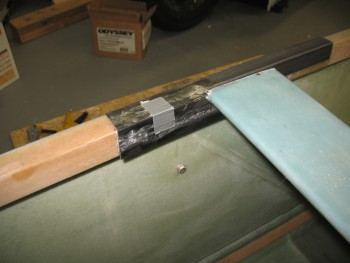
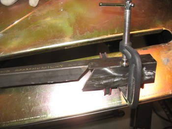
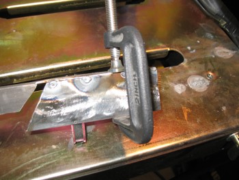
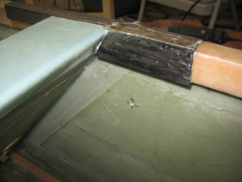
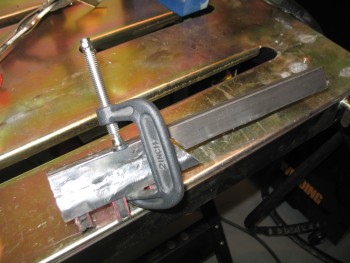
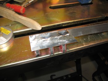
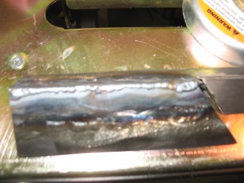
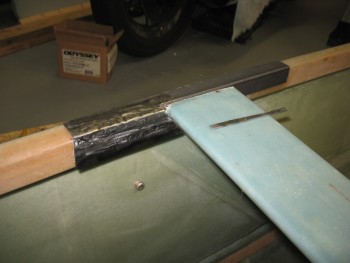
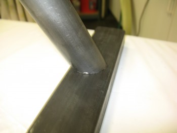
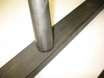
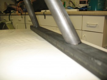
Chap 8 – Ugly Welds R’ Us!

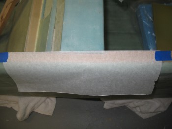
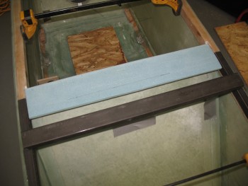
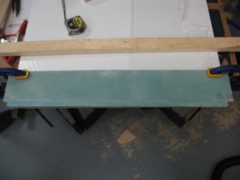
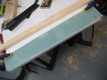
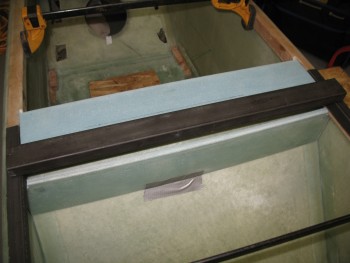
I started today by making a template for the outboard edge of each side rail.  I simply used a piece of tracing paper on each side and traced the outer edge just inboard of the longeron (one of the cool things about MGS is that it cures CLEAR).

Side rail edge template

I taped the tracing paper on each end and then drew the outline with a pencil.

Side rail edge template

Below are the side rail outboard edge outlines for each side.

Side rail edge templates

I taped the paper templates to their respective side rails & marked the outline.

Left side rail edge template

Then I prepped the right side rail first to cut.

Cutting side rail edge

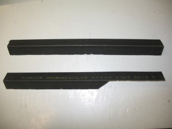
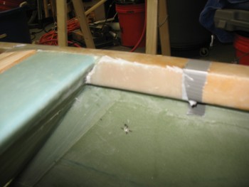
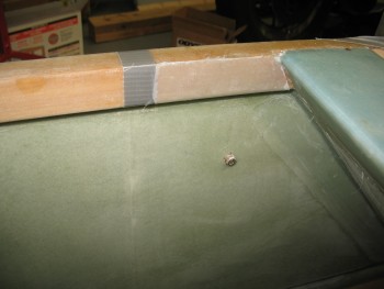
Below is the right side rail installed after I trimmed the outboard edge to match the profile of the longeron below it.  I also hacked off the aft triangular jut-out, a leftover from the extension I added to the side rail yesterday.  You can see how the extension now more than covers the entire width of the longeron aft of the seat (it gets trimmed below).

Right side rail edge cut

And then I did the same with the left side rail.

Left side rail edge cut

Here’s a quick shot showing the progress of the side rails up to this point.

Side rails' outer edges trimmed

Next, I fitted the right side rail’s inboard side-longeron piece (that I made yesterday) and marked up the intersecting line on the top side rail piece extension (that I also added yesterday).  I transferred the cut line on the bottom side of the side rail extension to the top & then cut it.  I then did the same for the left side.

Cutting inboard aft side rail

Here’s the left side showing the top side rail extension piece cut & matched to the inboard side-longeron piece.

Left inboard aft side rail

I then prepped the right side rail extension piece to weld to the longeron side-piece.

Right inboard aft side rail

Right longeron side-piece tack welded.

Welding right inboard aft side rail

Right side rail.

Right inboard aft side rail welded

Left side rail prepped for welding.

IMG_0592

Left side rail tack welded.

Welding left inboard aft side rail

Left side rail welded.

Left inboard aft side rail welded

Left side rail.

Left inboard aft side rail

Right side rail front extension piece.

Lower extension front right side rail

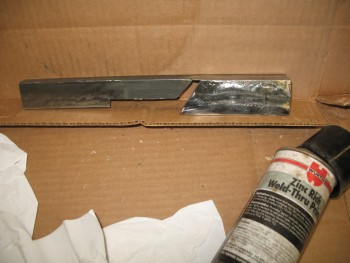
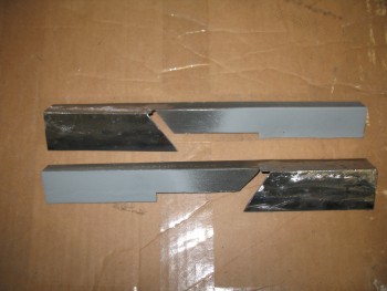
I’ll be adding a 4″ reinforcement plate to the front side of the side rail.  To keep any potential corrosion at bay, I sprayed the metal that I’ll be welding this plate to with weldable primer.

Applying weldable PrimerHere are both side rails prepped with weldable primer in the area that will receive the forward reinforcement plate.

Weldable primer applied

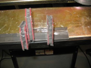
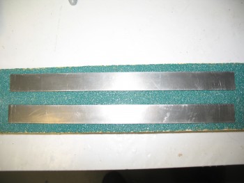
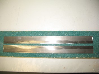
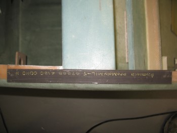
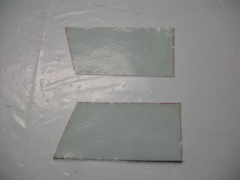
Speaking of the front reinforcement plate, here are the three 3/4″ x 4″ strips that I’ll weld to make up these 2 plates.

Forward side rail reinforcement

Once welded, I’ll cut the new plate down the center to create 2 plates 4″ long by about 1-1/8″ wide.

Forward side rail reinforcement


Chap 8 – More Side Rails

I started out today by confirming the measurements & angles of the aft seat side rail plates.  These plates will get welded to the top side rail pieces and will sit just aft of the front seat & against the longerons.

Interior side rail pieces

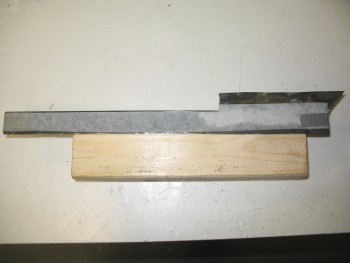
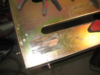
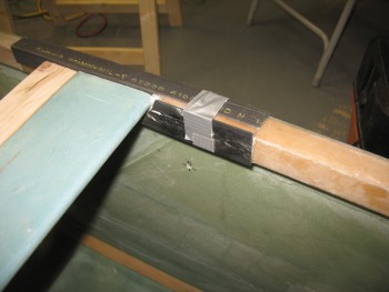
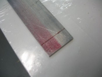
To make these 1-1/2″ high plates, I needed to weld two 3/4″ wide 4130 strips together.  I prepped the edges of each 4130 strip.

Interior side rail pieces

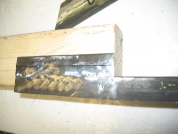
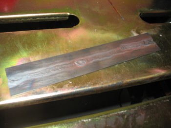
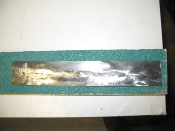
I could have spent a fair amount of time practicing my TIG welding, but I figured I would start in and give it a try.  Having a fair amount of experience welding I knew the difference would be between good looking strong welds–with a good amount of practice–or strong welds that may not come out as sexy looking.  Another issue was that the filler rod I have on hand is a little too big for this weld, so it was a bit of challenge in adding filler metal to the weld.

Here’s the resulting ugly but effective weld.

Interior side rail piece

And here’s the piece after I cleaned it up.

Interior side rail piece

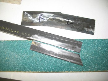
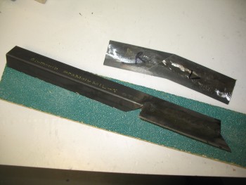
I then marked it & cut it diagonally so that the separate pieces fit in the aft seat spot.

Interior side rail piece

After tweaking the aft seat side rail plates for each side, I prepped the right side top rail piece (shown in the pic above & below) so I could weld an extension tab onto it at the aft end.

As a reminder, I should note that when I originally widened my fuselage by 1.4″, I also widened all the longerons from the front seat aft, top & bottom, to bring their inside edges inboard to allow the engine mounts to fit correctly.

Top side rail piece (& interior pieces)

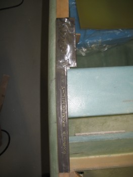
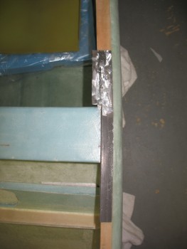
Here’s the right side rail below with the extension piece added on.

Top side rail piece (& interior pieces)

I did the same for the left side top rail, welding an extension to it as well.

Chap 8 – Rollbar Side Rails

This afternoon I started cutting the rollbar side rails to prep them for the extensions I’ll be welding on them.

Cutting side rollbar side rails

As I cut each side rail, I also cut a groove between each side of the seat back shelf edge & the adjoining longeron.  It took a few iterations to get the side rail to slide in, but the fit on each side is still fairly tight.

Cutting side rollbar side rails

Here’s a view from the front showing each side rail cut & in place.

Cutting side rollbar side rails

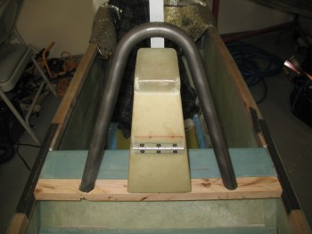
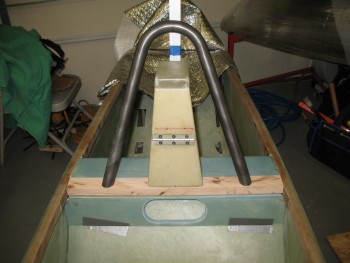
I then cut & added the wood cross bar mock-up with the rollbar installed.

Cutting side rollbar side rails

Chap 8 – Seatback & Roll Bar Construction

I started off today by knocking out the two quick aft seat BID reinforcement layups.  Just like the reinforcement layups on the forward side of the seat, the longerons just aft of the seat will get 2 plies of BID to reinforce the respective longerons for the Rollbar assembly side rails, and to give the aft 1/4″ bolt a little more meat to bite into.

I sanded down the existing glass to prep it for the layups.  I then marked the aft edge of the layup with duct tape, which will of course align with the aft edge of the rollbar side rails.

Aft seat BID layup prepAft seat BID layup prep

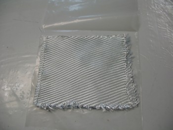
I tracked down 2 plies of BID and cut them to the approximate size needed, as well as the appropriate sized piece of plastic sheet required for the pre-preg setup.

Aft seat BID pre-preg prep

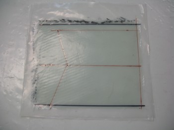
I then whipped up some MGS 285 epoxy with fast hardener and wetted out the BID in the pre-preg setup.  I then marked up the plastic with Sharpies and cut out the individual pre-preg layups for both the left & right longeron.

[Note:  In my haste, I marked up these pieces incorrectly since I used the measurements at the top of the longer to the seat back, and then bottom edge of the longeron to the seat back.  Since these–like the front ones–don’t cover the top of the longerons, and only cover the inside edge and bottom, I mistakenly didn’t account for the bottom 0.7″ when I marked these.  No big deal since it only results in a slight gap near the seat back].

Aft seat BID pre-preg prepAft seat BID pre-preg prep

I then completed the longeron BID reinforcement layups on each side.  Here they are completed, peel-plied & curing.

Aft seat BID reinforcement layupAft seat BID reinforcement layup

The first thing I did as these layups were curing was to quickly knock out the roll trim mounting tabs (detailed in the post below ↓).

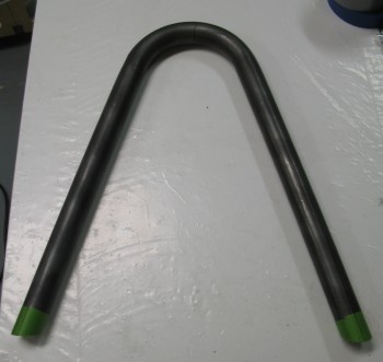
I then worked on the rollbar.  My first order of business was to shorten it so that it reached my approximate target height of 13″.  Since the angle & fit was good on my initial cuts, I “simply” needed to replicate those cuts to shorten the rollbar.

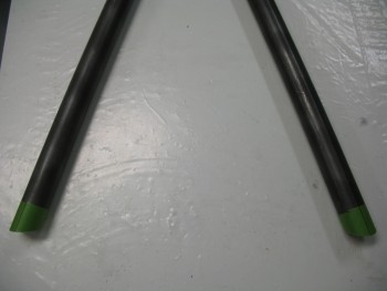
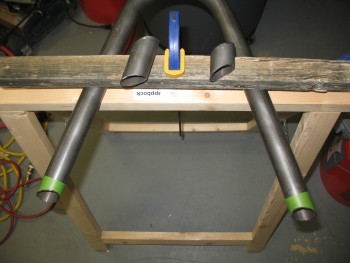
I did this by drawing a reference line near the top center of each rollbar leg.  I then wrapped green painters’ tape around the end of each tube.

Rollbar leg reduction

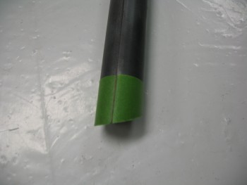
I cut the tape to match the contour of the bottom of each tube.

Rollbar leg reduction

And then marked the reference line down the top center of the tape in line with the previously marked reference line.

Rollbar leg reduction

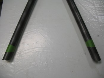
With the bottom edges of the tape contoured to the existing cut angles, and my reference lines marked, I marked the distance from the bottom edge for the new cut lines.  I then simply removed the tape carefully from the bottom of each rollbar tube and moved them up to the marked cut line, while ensuring the tape was aligned with the reference line at both the top & bottom of the tape.

Rollbar leg reduction

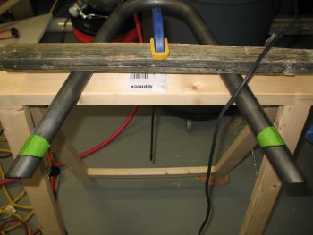
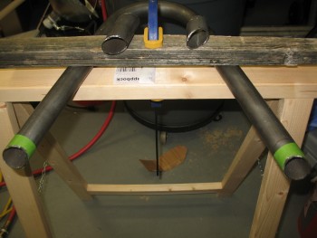
With my new cut marks set I clamped it down and using my Dremel Tool, cut the rollbar down tubes to their new lengths.

Rollbar leg reduction

And here it is shortened to its new height.

Rollbar leg reduction

Rollbar leg reduction

You probably noticed that one leg of the rollbar was cut shorter than the other.  The reason for this is that with the inverted “V” geometry of the rollbar, I can embed one leg of the rollbar into the cross bar so that I can weld it at both the top of the cross bar and the bottom, while the other side rollbar leg only gets surface welded to the cross bar.  This should allow for a stronger rollbar than if only each side gets surface welded (make no mistake, I believe that would still make for a very strong rollbar as well), and it also opens up access to the right rollbar tube on the bottom of the crossbar to run any cable(s) through the rollbar tubing if I should ever want to mount a video camera, or other device requiring a cable.

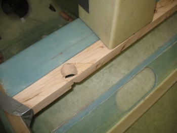
With the above in mind, I drilled a hole in my wood cross bar template ONLY on the right hand side to allow for the right rollbar leg to sit down inside the crossbar.

Rollbar mockup

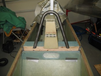
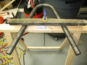
I of course had to play around with it for a bit and use a small sanding drum to contour the inside of the mounting hole, but I got it fairly close.  Below is the mocked up rollbar with its new adjusted height.

Rollbar mockup

I’ll of course need to fine tune it, but I think it looks pretty good.

Rollbar mockup

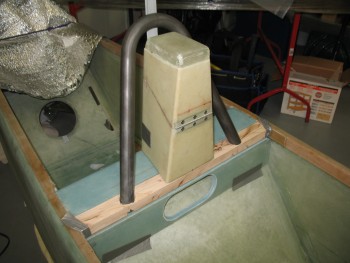
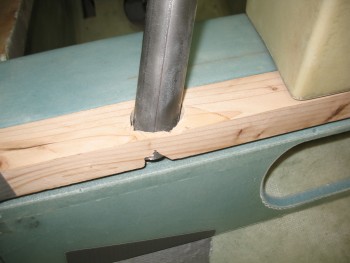
Here’s a closeup of the right rollbar leg as it sits embedded in the wood cross bar mockup.

Rollbar mockup

Chap 17 – Finishing up the Roll Trim

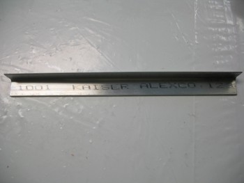
The only I thing I needed to construct to finish up the roll trim as per Waiter’s detailed instructions was the two 1/16″ thick 2024 aluminum angle tabs.  These tabs hold the X-Tube to the control tube (which transits down the side of the fuselage).

I didn’t find any angled 1/16″ 2024 aluminum as I rooted around in all my metal stock, but I had a nagging feeling that I had ordered a piece.  Thus, last night I carved out some time specifically to research the case of the missing angled aluminum (queue dramatic music).  A significant motivation for me to look was that it was going to cost about $17 to have a $3.50 piece of aluminum sent to me from Aircraft Spruce.

First, I found it in on my master spreadsheet and I had even listed it as being for the roll trim build.  That meant that I should have it on hand.  With various parts of my EZ project literally having been scattered about 5 locations around the world, I thought maybe I might have lost it in transit.  Well, I then checked my invoices and found the box that it had been shipped in, along with the aluminum tubing for the fuel lines.  Since it was wrapped in brown paper at the bottom of a tall box, I had missed it at the bottom, dimly lit corner behind & below all the various tubing and wire bundles.

Anyways, an hour blown on looking for my aluminum angle piece, but the mystery was solved & case closed!

Roll trim tab construction

After I finished the aft seat 2-ply BID reinforcement layup and while it was curing (detailed in the post above ) I set my sites on knocking out the tabs for the roll trim assembly. This will finish up the actual construction of the roll trim assembly, and all that will be left is the installation & wiring up of the roll trim system.

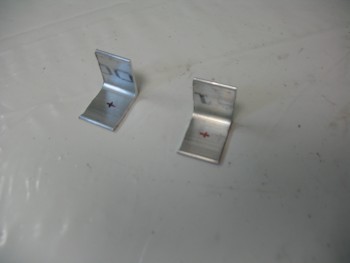
I checked each end of the 1/16″ angled 2024 to ensure it was square, which both sides were. Then after making a mark at 3/4″ I simply used my small chop saw with a wood blade, and very slowly cut the aluminum.  Repeat for the second one and voila!  Two tabs.

As per Waiter’s plans, I marked the spots for the mounting holes in center going top to bottom (3/8″) and 1/2″ from the side (this is 1″ x 1″ angled 2024).

Roll trim tab construction

I drilled a small pilot hole in each tab, then finished up with a 3/16″ hole.  I deburred the holes & then checked the fit of the AN3 bolt.

Roll trim tab construction

I then cleaned up the edges with the Dremel Tool and gave the non-drilled side tabs just a bit of a radius where the pipe clamps will be located as they hold the roll trim assemble to the control tube.

I then mounted the tabs to the assembly.  They fit great and everything looks good.  I’ll Alodine these tabs later on when I do another batch of aluminum components.

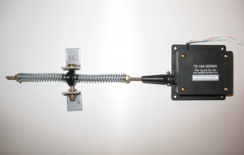
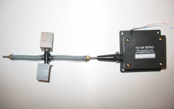
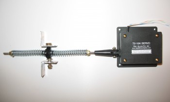
Here’s a few shots with the mounting tabs in varying positions on what I’m going to call the COMPLETED Roll Trim assembly!

Roll Trim Assembly

Roll Trim SystemRoll Trim Assembly


Chap 8 – Roll bar & seat back

This morning I started by carefully drilling the holes in the nutplate inserts I embedded into the seat back shelf that will serve as the rear bolt hardpoints for the headrest.  It took about 10 good minutes to dig out the saran wrap I stuffed into the nutplate on one, and about 5 on the other.  No surprise… nothing is predictable when building an airplane.

I had a couple shots that I took quickly but didn’t realize how jacked up they were until I downloaded them.  Just pics of the hardpoints and the initial (official!) mounting of the headrest to the seat back assembly.

I then went on a beautiful flight for almost 2 hours.  I of course didn’t get to see hardly anything because I was wearing foggles the whole time…   But, I did get to a watch a C-17 on final pass about a 1000 feet below us as we traversed Quantico’s Class D airspace.

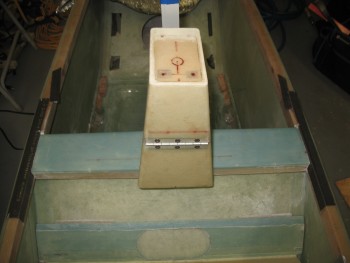
Ok, back to the build.  I cut a 2×4 into the size of the 4130 crossbar to use as a substitute for sizing, fit & checking out other components on the rollover assembly.  Below gives you a general  idea of what the base will look like with the headrest and the crossbar in place.

Headrest mounted to seat back shelf

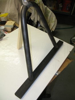
I measured, mocked up and trial fitted the rollbar a number of times to get the correct angle and initial dimensions figured out.  Since my rollbar will be slanted aft, figuring out the cut angle was a little tricky (at least for me…).

The lean angle on my roll bar is 69° so I cut the end of a piece of scrap wood (actually the one below holding the rollbar down) at 21° to get the correct template.  I verified the angle & it was spot on.

I messed with the rollbar and contorted my mind a few times to figure out how I was going to get a straight cut across the bottom of the rollbar to make each side level with each other on a flat surface, but then add the angle in for the aft lean.

I decided to work one axis at a time.  I figured out a line that if cut straight across the bottom, the rollbar could easily stand straight up with each side sitting flat on the surface. So on each side of the separate tubes I drilled a small hole along the plane of that line.

Then for the aft lean angle, I laid the roll bar flat & laid the scrap wood template piece next to it (with the 21° angle).  I marked the front side of each rollbar tube with the long side of the template, then drilled a hole on the top center of the tube as it lay there on the table. Then I flipped the rollbar and did the same thing on the aft side with the short side of the template.

When I was done, I had 4 holes on each tube, 90° from each other as for as the cardinal center lines of left, right, top, and bottom of the tube, but all over the map in any semblance of an identifiable relationship.  I took a Sharpie and as I started literally connecting the dots, I could see that the key to understanding the line was the cut angle and the flow around the curves of the tube.  At that point I was fairly certain that I had a good cut angle for mating the rollbar to the cross bar.

I clamped the rollbar to a sawhorse & used my Dremel Tool to cut the tubing at the lines.

Roll bar - initial cut

Now, I targeted the lower parts of each down tube of the rollbar to give me a lot of wiggle room to lock in the cut angle.  I could envision a number of iterations required to lock in this cut.  Well, that didn’t happen.  I actually got it right the first time around!  Which is a little annoying since IF I had known that I was going to get the cuts so good right out of the gate, I would have just marked the rollbar in the correct spot and been done cutting some fairly hefty 4130 steel!!  Ha!

Too high, so perfect first cut!!!

Here’s a close up shot.  I’m happy that I cracked the code, but man I wish that this was correct dimensions so I could weld this puppy up!

Look at that!

And this!  Totally weldable!

And the money shot….

Hope the next cut's this nice!

Here’s a pic showing the general feel of how this will look when it’s put together.  Also, the rollbar is definitely too high and will be getting shortened another couple of inches.

Mock up... will chop more off.

Chap 8 – Finally getting somewhere!

After days of seemingly micro steps (pardon the pun), I finally feel like I got some heavy lifting done on the seat back assembly.  I could have actually done this layup last night, but it was too late and I was too tired.  So this morning I was able to jump right in and get started.

My first order of business was scrounging for BID for the seat back shelf to existing seat back layup.  The plan is to use a 4″ wide 2-ply BID layup under the front part of the seat back shelf since that’s all the support glass that the front of the seat top will get.  The aft side of the seat will only get 1-ply of 2″ wide BID since I’ll be adding 2 more plies of BID on top of the rear BID tape in the final layup of the seat back shelf.

Below is the 4″ wide 2-ply BID that I wetted out for attaching the front & underside of the seat back shelf to the existing seat back.  Since this is the only layup going in here, I won’t be peel plying it.

Pre-pregged BID for seatback

I slathered up the foam on the seat back shelf assembly with micro.  I then filled the spike holes with flox.

Seat back attack ready to commence!

And then did the same on the foam for the existing seat back.

Seat back slathered!

I laid up the 4″ wide 2 ply BID tape on the front side to attach the 2 seat parts.  The top side was overlapped with about 1-1/2″ of the 4″ inches, while the bottom existing seat back get the rest of the BID tape (about 2-1/2″).

I then wet out the 2″ wide 1-ply BID in a pre-preg setup for the layup on the aft side of the seat.

Aft pre-preg for seat back.... 1 ply

Although hard to see, below shows the seat front side layup.  I peel plied just the bottom edge with 1″ peel ply tape to keep the edge transition smooth and fiberglass barb free!

Seat back: floxed, micro'd & glassed

And here’s the aft seat layup.  Since there will be more BID added to the aft side of the seat, I peel plied this layup.

Aft seat back layup

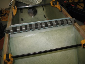
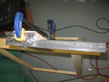
To keep the top edge of the front part of the shelf straight, I pressed the rollover cross bar into service and taped the edge to this rectangular metal piece.

Keeping it all straight & level

While the seat back was curing, I Alodined the 2 small 1/8″ thick 2024 aluminum plates that I used to house the nutplates after I riveted them into the aluminum pieces.

Alodined & riveted nutplate assemblies

Here’s a closeup of the nutplate assemblies that will be used to secure the middle screw on the roll bar assembly side rails.

Alodined & riveted nutplate assembliesYou’ll note that one nutplate assembly is shorter than the other.  That’s because I was trying to shape these assemblies in order to make them fit under the longerons before I realized that I needed to go another route (aka “Plan B”).

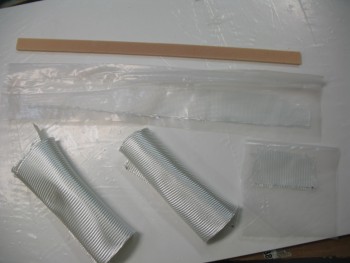
I started prepping for the next couple of layups by cutting the glass & plastic for the pre-preg setups for the BID required to cover the nutplate assemblies on the seat back shelf, and the 2″ wide 1-ply BID tape that I’ll use to glass the 1″ foam strip under the front lip of the seat back shelf.  Finally, I had to actually pull some BID off the roll and use my glass cutting table to get the 2 pieces required for the seat back shelf top layup (the rolled up glass below).

Glass for seat back shelf layup

I used thin screws and fast hardener to attach the 1″ yellow foam piece to the front lip of the seat back shelf.  The yellow foam piece will be the back “wall” of the notch in the seat back assembly that the 4130 steel roll over crossbar will be resting in.  The 2″ wide 1-ply BID tape was laid up on the aft side of this yellow foam piece and with the bottom side of the adjoining seat back shelf.

1" yellow foam lip glassed in

Here’s a quick shot of the peel plied pulled from the aft seat layup, and then a fairly robust sanding I gave it to smooth out some of the rough edges between the 2 seat pieces.

Aft sanded & prepped for final glass

Being a cheapskate, the flox from the first layup was still good so I used it to mount the nutplate assemblies into the top of the seat back shelf and also to fill the holes leftover from the screws I had just removed.

By using the fast hardener and setting heat on the 1″ foam lip layup, it cured in no time flat.

Nutplate assemblies in & holes floxed

I started the layup on the top side of the seat back shelf by working the pre-preg for the BID inserts that go over top of the wood nutplate assemblies.  Of course these make up the rear bolt hardpoints for the headrest.

Seat back glassed - 2 plies BID

After I got the 12-plies of BID situated as neatly as possible in each of the nutplate cutouts, I micro’d all the foam faces to prep for the upcoming 2-ply BID layup (shown below after I peel plied it).

Seat back peel plied

Here’s the main layup shown from the aft view.  Also peel plied.

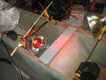
Aft seat back view - peel plied I bought some heat laps quite a while ago in preparation for building my fuel tanks, so I decided to see how they work here & see if they’ll give the layup a boost in its cure time!

Seat back under interrogation!

Chap 8 – Seat Back & Rollbar Prep

Today I started out by laying up some reinforcement BID on the longerons, which will lie directly inside the roll bar side rails.  I wanted to add some reinforcement to buttress up the longerons to give the roll bar bolts just a little more to grab a hold to.

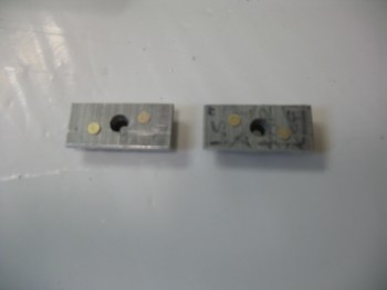
Now, to back track just a bit.  I was planning on glassing in a nutplate riveted to a piece of 1/8″ 2024 aluminum (see pic below) under each longeron to allow me to install a countersunk screw in the center-“ish” position on each of the side rails as one of three attach screws/bolts on each side of the roll bar. However, as I was cleaning up the underside of each longeron to ready the floxing/glassing in of these nut plate assemblies, I realized that the original flox fillet in the corner between the fuselage side wall and the underside of the the longeron was keeping the aluminum plate from sitting level.  After messing around with it for a bit, it was clear that the nutplate assemblies would only sit slanted with the underside of the longerons in their current state, no matter how clean the undersides of the longerons were.
Rollbar side rail middle bolt hardpoint

I also realized & had accounted for the fact that positioning the roll bar side rail middle mounting hole was going to be a bit difficult to align with the longeron hole/nutplate assembly since the side rail would have to be drilled at a later point, while the longeron would have to be drilled prior to mounting the nutplate assemblies to ensure they were aligned correctly with the mounting screw hole.  Of course it’s always easier to get all the associated components together, ensure all is aligned and then drill it all in one shot.  This method is definitely what I preferred to do.

So I went with Plan B, which involved a 2-step process for the center side rail mounting screw.  First, I would glass in a small 1/16″ thick phenolic shim, 0.35″ in width (half of the longeron’s 0.7 width).  The phenolic gets glassed in on the interior underside of each longeron at the point the nutplate insert will get installed, with the inboard edge of the phenolic shim even with interior edge of the longeron.  The resulting gap behind the phenolic shim then gets filled in with thick flox, and voila, a straight bottom surface is created on the longeron to mount the nutplate assembly AFTER the side rail is in place, and both the side rail and longeron can have the middle screw mounting hole drilled simultaneously. Once the side rail and longeron are drilled, I’ll install the mounting screw from the top to secure the nutplate assembly on the underside of the longeron, at which point I’ll flox & glass the nutplate assembly in permanently.

So to start, I pre-pregged 2 plies of BID.
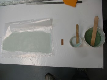
Pre-preg BID for side rails

Here’s one of the phenolic shims.  The pic’s not the greatest, but you can see a little bit of the quick sanding I did to rough up the surface a little for better bonding to the epoxy.
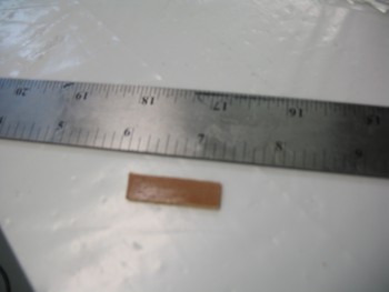
Phenolic under-longeron insert

And here are the side rails reinforcement layups.
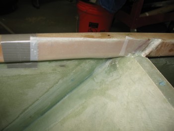
2-ply BID longeron reinforcement2-ply BID longeron reinforcement

Ok, now that I wrote the novella above to tell the story for two mere simple layups of 2 plies of BID on each longeron, I will regale you with yet another tale. The minor issue that I wanted to resolve was that I wanted access to the interior side of the seat back top assembly.  Primarily for two reasons:

1.  Construction of the seat back assembly
2.  Storage

I’ve been bantering this around in my mind for the past few days, and was thinking about cutting out a rectangular hatch on the lower back support, and possibly hinge it and secure it with some type of latch.  Well, I had an epiphany and decided to not only hold true to K.I.S.S. but save a little weight and go traditional in keeping with Burt’s style. Thus, I would simply cut an oval shaped hole, radius the edges and call it a day! This gives me the access I want, saves a little bit of weight, and looks kind of cool (I think!).

I grabbed a piece of scrap wood and threw some duct tape together to create a seat back hole mock-up.
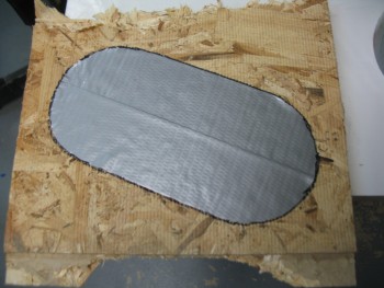
Storage opening mock-up

After I traced out the tape & before I cut out the oval test access hole, I thought I should start smaller and work my way out.  I drew another hole outline about 1/4″ inside the first one and used this as my cut line.
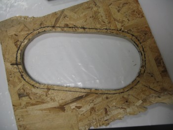
Storage opening mock-up

Then I tested the available access space.  Since I could actually move my hand in & around very freely, I narrowed the height of the hole by another 0.2″ and shaved about the same off the width.
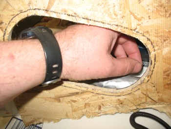
Storage opening mock-up

I took my finalized dimensions upstairs and created a template on graph paper, cut it out and had my new access hole outline template ready to go.

Back in the shop, with the lower seat back piece in hand I knocked out some clean-up tasks first by trimming the rear glass overhang–at the aft side of the 1/4″ yellow foam–down to 1/4″ to match the strip of yellow foam that will connect the upper seat back shelf assembly to this assembly.  I also sanded it down for a good gripping edge since I had forgotten to peel ply this edge (yeah, what gives??  I love peel ply!)
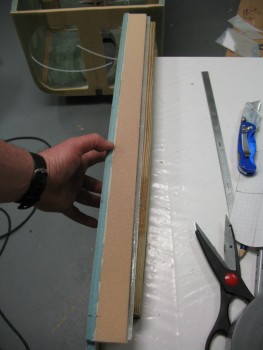
Glass overhang trimmed

Then I used my newly made template and traced around it on the INSIDE of the seat back, since that was where all my clearance issues had to be accounted for.
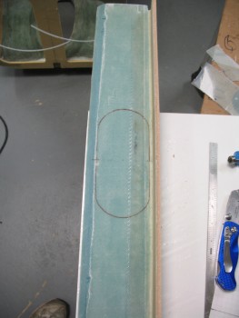
Back rest storage opening mod

I drilled a starter hole & then used my jig saw to cut as much as I could on the back side of the lower seat back assembly before my blade guard hit the yellow foam piece.
[Note:  You may notice some air bubbles in the micro fillet at the corner of the blue and yellow foam.  I’m fairly certain that this was caused by my having to re-position the yellow foam a number of times to get it to line up 90° to the blue foam.  I would stipple the air out with a brush, have to tweak the position of the of yellow foam (since I wasn’t using a jig) and then the bubbles would reappear.  I was more concerned about angular positioning than the bubbles, since I’ll simply inject those later].
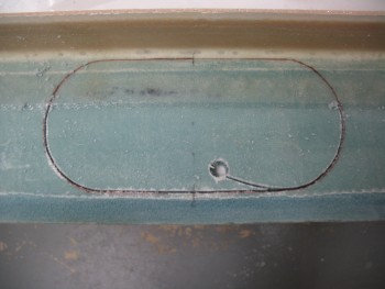
Back rest storage opening mod

I then flipped it over, tweaked the outline to ensure it was straight and finished cutting out the hole.
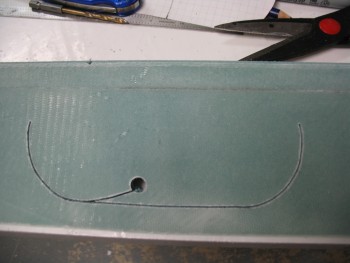
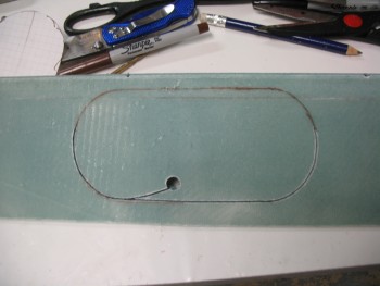
Back rest storage opening modBack rest storage opening mod

After the hole was cut, I sanded down the edges and verified the glass edge on the BACK edge of the hole was straight (since that’s the edge the router bit roller will be using as its guide).
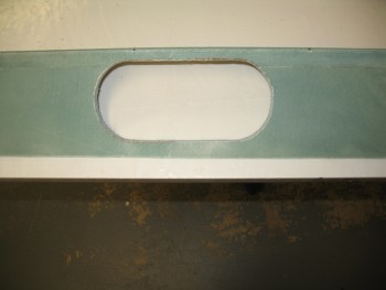
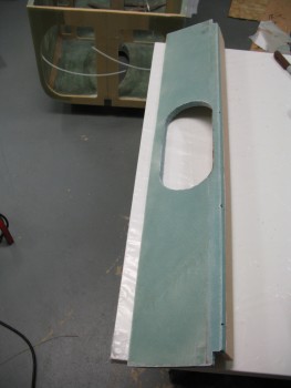
Back rest storage opening mod

Back rest storage opening mod

Then I took this puppy out back, clamped it to a sawhorse and routered a 1/4″ radius on the access hole’s edge.  I was going to try to go with the same style as the CS spar oval access hole as far as the hole’s edge, but I simply didn’t have enough clearance to work with.  So, except for the straight bottom edge of the oval, I’ll cut a wedge out of the foam on the back edge and create an internal flox wedge to strengthen the glass at the hole’s edge.
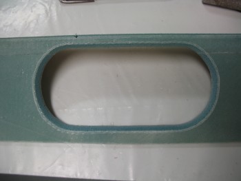
Back rest storage opening mod

Sorry for the crappy pics below, but they show the cured 2-ply longeron layups that will add a base & some strength for the rollbar side rails.  I specifically DIDN’T add glass to the tops of the longerons simply to avoid adding height to the side rails in order to minimize clearance issues with the canopy frame.
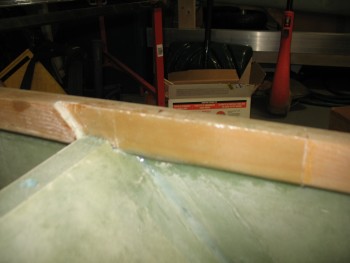
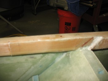
2-ply BID longeron reinforcement2-ply BID longeron reinforcement

And here’s a shot with the lower seat back piece with the newly cut access hole thrown in place for a quick mock-up.
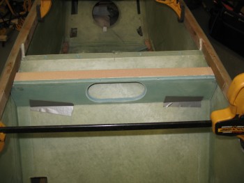
Back rest storage opening mod

And a head on shot of the same.
Back rest storage opening mod

Chap 8 – Lower Seat Back Layup

I started with a list of about 10 things to get done today.  Well, I finished 2 of them! Between getting a late start and going out to dinner with friends this evening, I was merely able to get the lower seat back glassed.

I prepped the 1/4″ thick x 1-3/8″ yellow foam addition by adding a couple of extensions covered with duct tape to the outer edge of the yellow foam piece.  The reason for these extensions is that when they’re removed after the glass cures there will be about a 1/4″ glass overhang for the connecting foam piece that will be glassed in from the top side seat back assembly.  In short, this glass overhang will be the meeting point between the lower seat back assembly and the upper seat back assembly.

Lower seat pack piece

I then scurried up a piece of BID for the layup.

Layup Glass Prep

And some for the BID tape that I’ll be laying up in the corner to add strength.

BID tape pre-preg prepped

I micro’d up the foam and added a fillet in the corner.

Foam micro'd

I laid up the large ply of BID first, then laid up the corner tape.  Once that was all finished I peel plied the lower edge and the corner tape.

Layup finished

A few hours later I razor cut the piece, pulled the peel ply and cleaned it all up.

Trimmed & peel ply pulled

Below shows the 1/4″ piece I added to the lower seat back piece, and the glass overhang on the aft side of the yellow foam.

Under cross bar piece

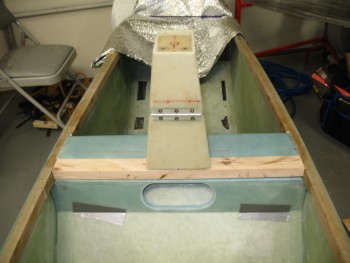
Of course I mocked up the newly glassed piece along with the other seat back components.  Below you can finally see the notch for the roll bar’s rectangular cross bar.

Latest seat back pieces mocked up

Latest seat back pieces mocked up

I added the cross bar so I could see how it all looks together.

Latest seat back pieces mocked up

Here’s a shot from from just a tad bit forward so you all can see the front edge of the cross bar aligned with the front edge of the lower seat back.  Looks like the fit should be pretty darn good.

Latest seat back & crossbar mocked up

And here’s the final mock-up shot of evening.

Latest seat back & crossbar mocked up


Chap 8 – Prep, prep, and more prep!

I would love to say that I got some really cool layups in today, but I can’t.  Today was all about prep.  And I mean I literally spent about 10 hours prepping a myriad of nitnoy things to get chapter 8 knocked out.

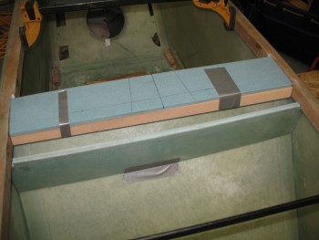
I started by spending about a 1/2 hour sanding the face of the seat back shelf so that it was as straight & level as possible.  Sometimes I feel more like a sculptor more than an airplane builder!  Once it was level, and I had it in the fuselage, I just wasn’t sold on the sharp edge that would make up the corner of the back of the seat and the new seat back shelf (headrest base) that I was working on.  I decided that I was going to radius that corner with a 3/16″ round-over router bit.

I clamped the piece to the work bench, and due to the edge being so sharp & the angle so great, I had to use a guide to keep the bit at the right position on the cut.

Radius'ing seat back edge

Here’s a shot of the aft side 3/16″ router cut on this piece.

Radius'ing seat back edge

I then radiused the front edge 1/8″.

1/8" radius seat back front edge

I mocked it up to check out the look of the radiused edges, and was happy with the results.

Seat back piece mock-up

Seat back piece mock-up

After I checked the seat back piece, I then radiused the top edge of the lower seat back piece using the same 1/8″ bit I used on the front of the piece above.

1/8" radius on lower seat back piece

Here it is after I routered the edge.

1/8" radius on lower seat back piece

I then added that piece into the mock-up.

More mock-ups

I turned my sites on getting the aft hard points for the headrest prepped so it’s ready to glass either later this evening, or tomorrow.  I measured out and marked the positions of the 2 aft headrest bolt holes.

Drilling aft headrest bolt holes

I then drilled the holes.

Drilling aft headrest bolt holes

Next, I started making the hardpoints that will sit opposite these aft bolt holes in the headrest.  These hardpoints will be mounted in the foam that makes up the seat back shelf, much in the way that the original Long-EZs had their seat belt hardpoints configured.

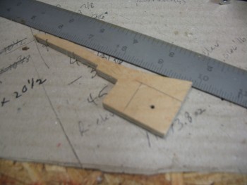
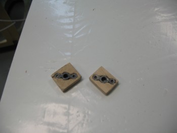
I started by grabbing some 1/4″ Birch Plywood to use as my hardpoints.  I’ll also be using the K1000-3 nutplates.  I marked up the first hardpoint using the K1000-3 as the determinant for my dimensions.

Headrest bolt hard points in seat back

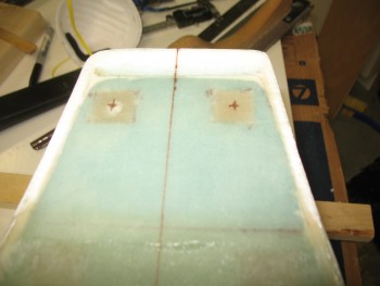
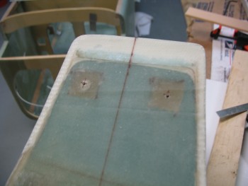
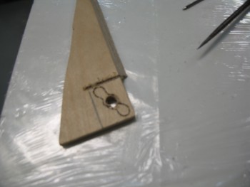
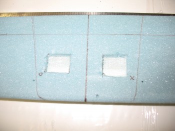
After I drilled the center hole large enough that the stem of the K1000-3 nutplate would fit inside, I traced the nutplate and used my razor knife to make a pocket for the nutplate to fit in so it will sit flush as its embedded inside the foam mounting point.

Headrest bolt hard points in seat back

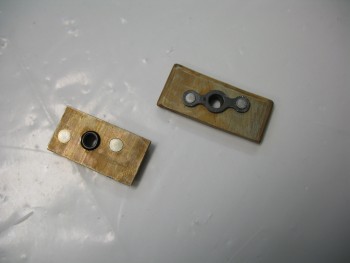
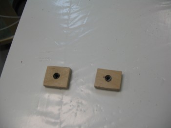
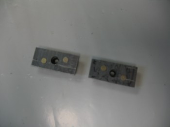
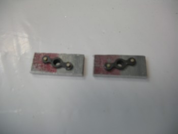
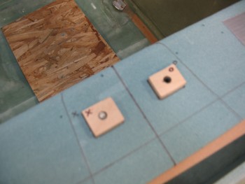
Here’s the 2 nutplate assemblies that I’ll embed so that they become the aft hardpoints for the headrest assembly to bolt to.

Headrest bolt hard points in seat back

And the reverse sides.  BTW,  I intentionally made these slightly different sizes in order to tell them apart and not get them confused during the installation.

Headrest bolt hard points in seat back

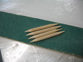
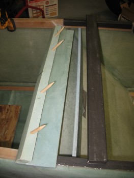
I set the headrest’s aft hardpoints aside and made up 4 dowel guide pins to help the new seat top with the existing seat, especially as it’s curing.

Seat back alignment dowels

Here’s a picture of them installed in the new seat top piece.

Seat back alignment dowels installed

With the seat top ready to go, there was still something I needed to complete before the seat top gets glassed in permanently.  The roll bar will be bolted in from the inside of the longeron out using 1/4″ bolts at the very front of the side roll bar longeron rails, and at the aft end of the rails.  In the middle area, where the new composite seat assemble will be built, I won’t have access to install a bolt there, since the entire area will be encased with the seat back assembly.  So the third, and middle hard point for the roll bar will be a 3/16″ screw that will be installed from the top to the bottom of the longeron.  Since the longeron isn’t that wide, I will be using a 3/16″ screw to ensure a lot of strength, but also minimize the cross section of the hardware installed in the longeron.

Again, since I won’t have access to that area, I can’t secure the screws with the traditional nuts & washers.  For this endeavor, I’ll again use a K1000-3 nutplate. However, instead of mounting it into wood, I’ll be riveting the nutplates to 1/8″ 2024 aluminum backing plates.
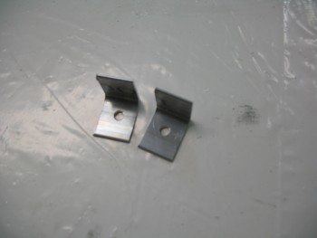
Rollbar side rail middle bolt hardpoint

Here’s the nearly finished set.

Rollbar side rail middle bolt hardpoint

And from the other side.
Rollbar side rail middle bolt hardpoint

Tomorrow I’ll shape the edges & then Alodine the aluminum before riveting the nutplates to the pieces.
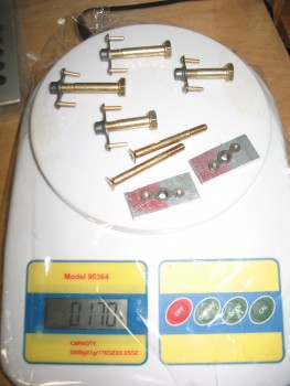
I also spent a decent amount of time figuring out my hardware requirements for the rollbar assembly.  I was curious about the weight of the hardware, so I threw them all on the scale: 0.17 of a pound.  Not bad!

Entire rollbar attach hardware

With that out of the way, I started mocking up the headrest on the seat back shelf so I could determine exactly where the headrest hardpoints needed to go.

Determining rear headrest hard point positions

I measured, eyeballed, laser-sited, and double-checked the hardpoint positions before pulling the trigger on marking them up.

Determining rear headrest hard point positions

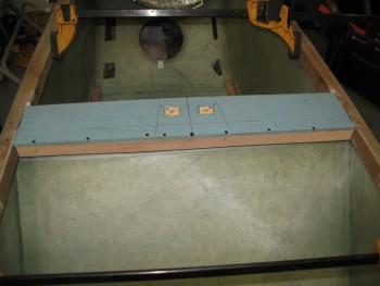
Here’s a shot of the headrest hardpoint positions prepped on the seat back shelf.

Prepping headrest aft hardpoint locations