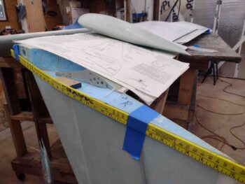
Chapter 20 – Right ‘A’ Block in place

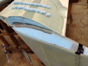
I started out today by removing the spacers, pulling the peel ply and trimming the glass on the right rudder Internal Bellhorn layup.

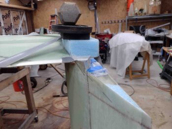
I’m not gonna lie, somewhere in my rush to get this thing installed, I placed it about 1/8″ forward than the left side.  Not sure why… but that’s where it ended up.  Is it the end of the world? No. Is it going to break the bank and make it not work?  Very likely not.  It’s just really frustrating to miss a detail like that!

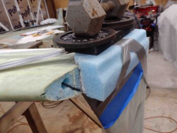
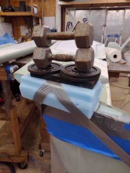
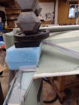
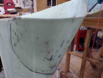
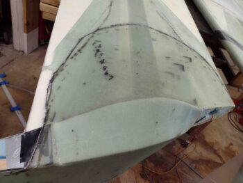
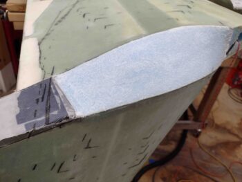
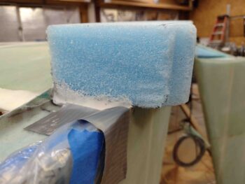
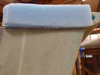
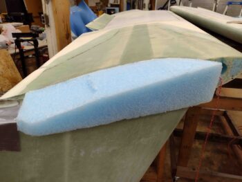
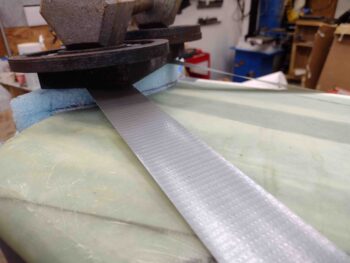
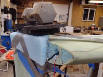
I then spent about 45 minutes shaping my blue foam ‘A’ block for the right side.  Once I felt I had a good fit (Oh, and let’s be real: Is there any certain way to ensure no air gaps other than pour foam? Com’n Man?!) I slathered micro on both sides, crammed a bunch of goopy micro all over both sides as well like a melted marshmallow sandwich and taped the crap out of it with duct tape to pull it in & down tight.

I then added a good little bit of weight to the top of it before heading out for an awesome Thanksgiving Dinner at Jessica’s.

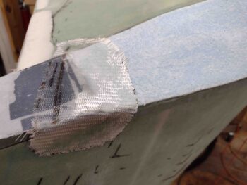
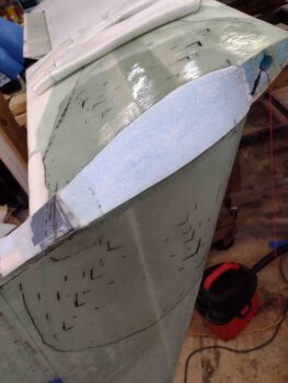
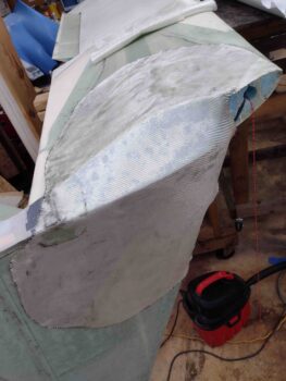
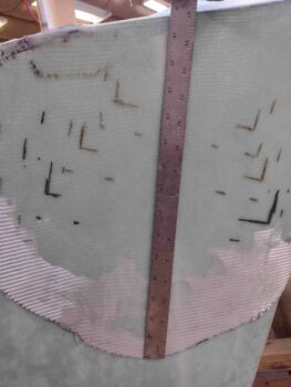
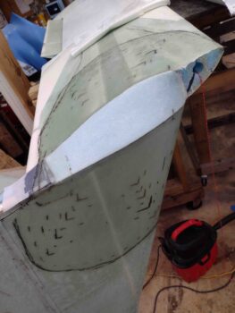
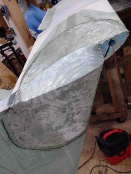
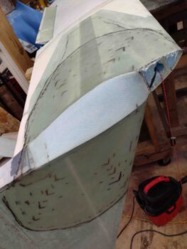
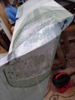
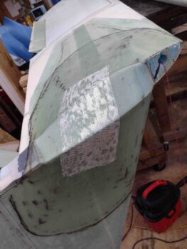
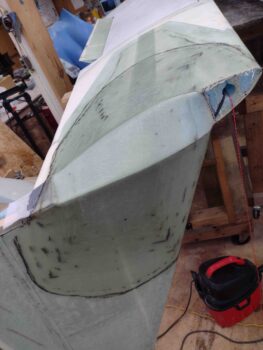
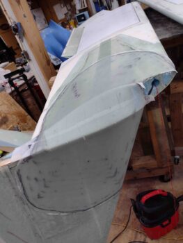
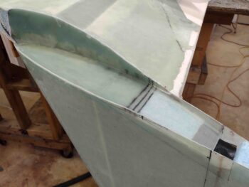
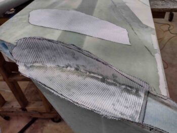
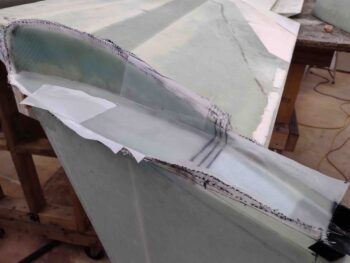
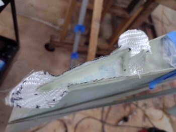
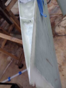
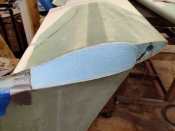
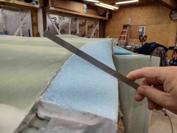
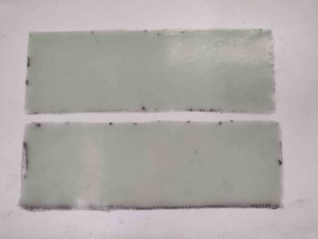
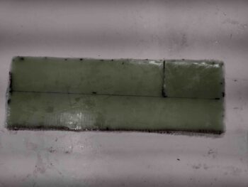
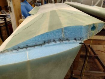
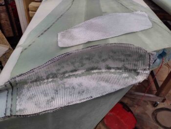
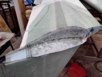
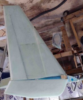
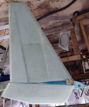
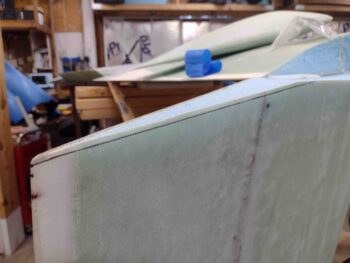
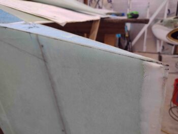
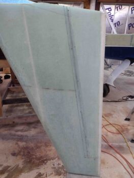
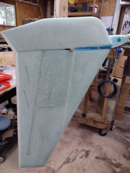
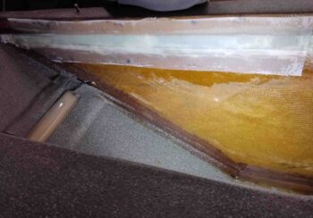
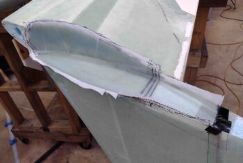
Earlier I did pull the peel ply (curiosity got the best of me!) on the left side Layup #3.  I have to say I’m very pleased with how this layup came out.

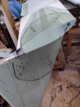
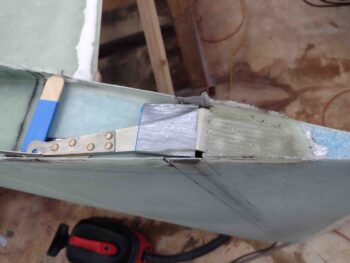
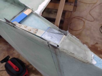
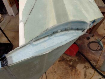
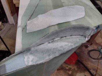
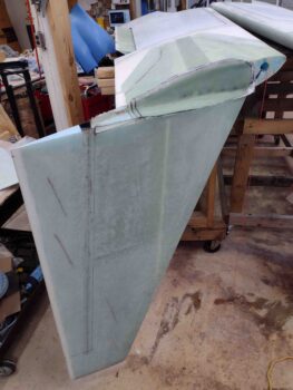
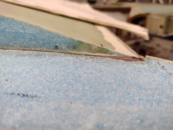
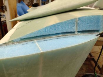
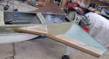
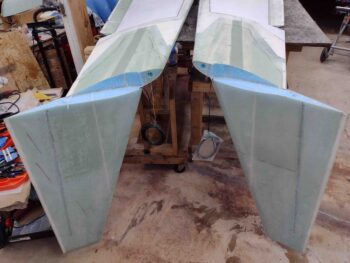
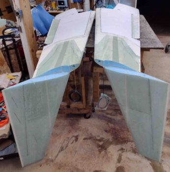
Here’s a couple more direct shots of Layup #3 from the winglet and wing side.

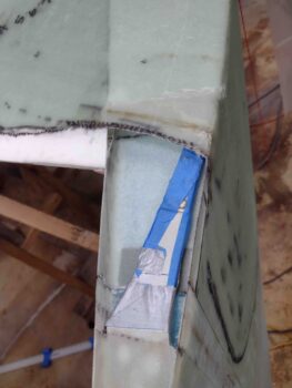
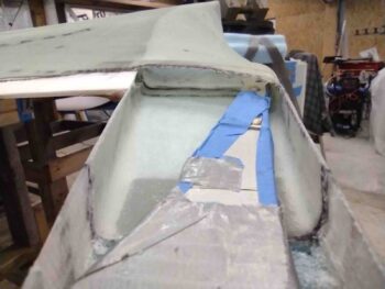
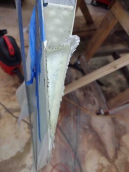
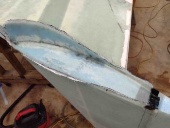
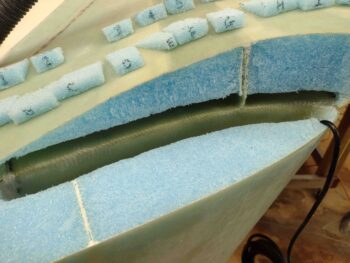
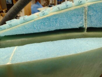
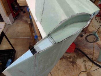
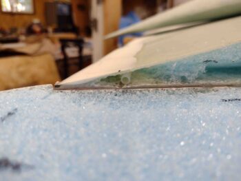
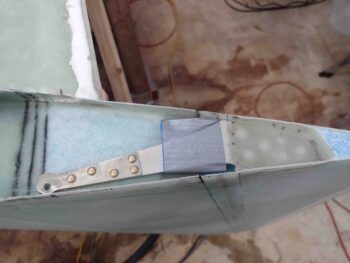
I then removed the Internal Rudder Bellhorn pocket mold and got a lot of the peel ply off the inside glass face.

I’m pretty happy with the strength, depth and height of the pocket and think it will work as designed!

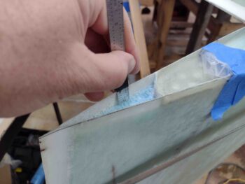
My last official build act of the evening was digging out 0.6″ of foam on the aft bottom edge of the right rudder to layup a ply of BID inside.

It wasn’t too awful late, but this constant building is wearing me out… so with this last little layup, I headed inside.  Tomorrow I plan on shaping the right wing/winglet ‘A’ Block and then laying up Layup #3 on the right side.

Pressing foward!

Chapter 20 – Left Winglet Outside Glass

My goal today was to get the left wing/winglet outside corner Layup #3 knocked out.

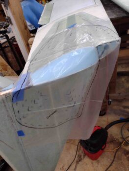
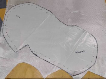
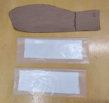
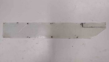
I started by using a large piece of plastic to create a pattern for the 2 large base plies of BID for Layup #3.

I then cut the plastic to create the Layup #3 BID pattern, and then used the pattern to cut the BID plies off the roll.

I then wetted out the peel ply over the Internal Rudder Bellhorn pocket mold.  I also applied wet micro onto the shaped blue foam ‘A’ Block.

I then added a small piece of reinforcement BID over the Internal Rudder Bellhorn pocket mold. As you can see, the BID ply overlaps onto the bottom wing edge, the outboard winglet edge, and blue foam transition block.

I finished wetting out the added reinforcement ply of BID over the Internal Rudder Bellhorn pocket mold, and then applied raw epoxy on the wing and winglet areas that will receive Layup #3 glass.

I then put in place the first large ply of BID over the wing and winglet.

I’ll note the plies of BID seem a bit large compared to the situated UNI plies.  Here I’m going to point out that the plans say to have the BID end 15″ from “the corner.”   I’m not exactly sure what corner the plans are actually referring to, so I just went with the longest practical measurement.  I’ll further note that the BID reinforcement plies on both the wing ends and the bottom of the winglet go fairly far inboard/up, respectively, so this 15″ BID dimension on each surface is well within the previously applied reinforcement BID layups.

Here we have the first BID ply in place and wetted out.

I then added the second large BID ply and wetted it out as well.

I then started laying up the 7 UNI plies.  First, the large UNI ply #1 (24″ x 12″) went on… then a fair bit later I finally laid up the last UNI ply.

The left winglet outside corner Layup #3 is complete!

I then peel plied Layup #3.

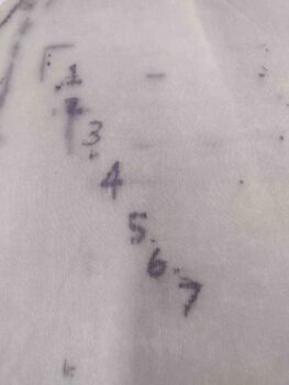
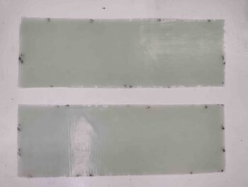
I saw this and had to get a pic of it: All UNI plies accounted for!

After finishing up the left wing/winglet Layup #3, I then trimmed and cleaned up the right wing/winglet Layup #2.

I then got to work installing the right winglet/rudder’s Internal Bellhorn.  After cutting and shaping the foam inside the forward rudder edge, I laid in 2 plies of BID and let it cure for a good bit before then floxing in the Bellhorn.  I then laid up 2 more plies of BID over the top of the floxed in place Internal Bellhorn.

I of course made sure the pivot angle and elevation was set and shimmed as the right Internal Rudder Bellhorn was floxed/glassed in place.

Finally, I peel plied the BID layup securing the floxed in place Internal Bellhorn.

And with that folks, I called it a night!


Chapter 20 – Right winglet Layups 1 & 2

My goal today was to knock out the right wing/winglet inside Layups #1 and #2, and also press forward with the prep for the left winglet’s Layup #3.

I started off by wetting out the 2 sets of prepregged 4-ply BID layups.  I then trimmed the layups to size: 4″ x 12″.

I then cut the 2″ deep slit at the position of the Shear Web. I also marked the center line of where the wing glass meets the winglet glass.

I then laid up the 8-ply Layup #1 into the wing/winglet corner joint.

I then started slathering up the foam wedges and putting them into place.

Here we have all the wing/winglet Layup #1 securing foam wedges floxed into place.

I then went to lunch and enjoyed a few hours off before coming back to the shop, cleaning up the wedges, adding some thick micro to any bare foam and then laying up the longer plies 1 and 2 of the right side Layup #2.

A bit later, here I’m adding ply 5 of Layup #2 to the wing/winglet outside corner.

After I laid up all 8 BID plies of Layup #2 on the right side, I then peel plied it …

Here is the right wing/winglet Layup #2 peel plied.

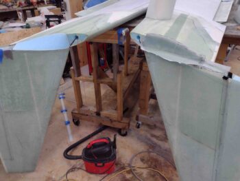
And here is a shot of the left and right winglet install progress.

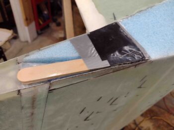
To ensure that the left Internal Rudder Bellhorn arm has a tall enough pocket to pivot in and out, I added some foam, stir sticks and tape as a mold to ensure that when the Layup #3 glass goes on that there is enough clearance for the Bellhorn arm.

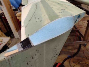
Here’s a wider view of the Internal Rudder Bellhorn arm pivot pocket mold at the aft end of the ‘A’ Block.

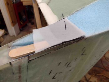
The final touch for the Internal Rudder Bellhorn arm pivot pocket mold is a piece of peel ply to help clean up the tape surface on the top of the mold.

With that, I called it a night.  Tomorrow I plan on glassing Layup #3 to secure the left winglet to the left wing.


Chapter 20 – Prep, prep, prep!

Knowing that today was pretty much going to be all prep work, I did want to get at least one small layup in under my belt.

Although I do prefer a flat inside edge of a control surface, I decided to follow the plans and dig out the foam down 0.6″ on the aft side of the left bottom rudder.  The plans call for laying up the top and bottom of the rudders with 2 plies of BID, but since I have a rather robust structure on the front half of the rudder with the Internal Rudder Bellhorn installed, I decided to go with only 1 ply of BID.  On the top I’ll go with 2 plies of BID.

I laid up the one ply of BID using fast hardener, since this isn’t a huge structural airframe layup.

Jumping ahead a few hours, I then razor trimmed the glass.  Here’s the result.

On the right wing and winglet, I made up both a wing-side and winglet-side set of foam wedges for Layup #1, as I did on the left side.

I also sanded and prepped the internal glass inside both the wing and the winglet, respectively.  In addition, I sanded the meeting corners to a radius, as best possible since both skins are fairly thin.  Lastly, you may note I configured the aft winglet by making a depression in the foam that will serve as the Internal Bellhorn arm channel.  I then taped up the aft border line of the winglet where it will meet the rudder, and a spot of gray duct tape where the aft inside channel of the winglet will be created by digging about 1″ of foam (I’m taking Ary Glantz’ advice and going about 1.2″ deep to allow more clearance for the rudder hinges).

I then prepregged the BID for the ring wing/winglet Layup #1, with 4 plies of BID in each prepreg setup.  I also cut out the Layup #2 BID template for the right wing as well.

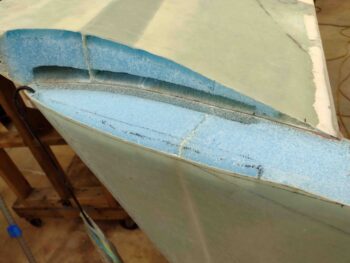
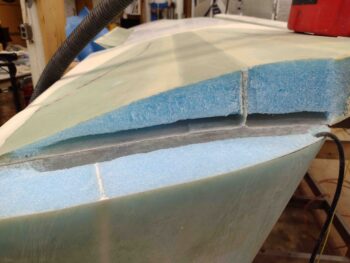
By this point the micro securing the left wing/winglet ‘A’ Block in place had cured, so I removed the tape and the weights.

Here’s a lower-up shot of the left wing/winglet’s foam ‘A’ Block secured in place with micro.

I then started slowly trimming down the left wing/winglet ‘A’ Block..

And then sanded the left side ‘A’ Block to shape.

Here is my requisite pic showing how flat the resulting sanding job is on the left side ‘A’ Block.

It wasn’t super late when I cut out for the night, but it was too late for me to start a fairly lengthy layup.  Tomorrow I plan on knocking out the right wing/winglet inside corner Layups #1 and #2 as a minimum, and hopefully get the left side Outside corner Layup #3 (2 plies BID + 7 plies UNI) prepped for the following day.

Chapter 20 – Left Internal Bellhorn In

I decided this morning that before I did my next identified task: micro in the blue foam ‘A’ Block into the pocket created by Layup #2 on the left wing/winglet, that I would first determine the install configuration of the left rudder’s Internal Bellhorn and then flox and glass it into place.

Last night and this morning I did a lot of reviewing of other builders’ blogs, specifically Dave Berenholtz and Ary Glantz.  Dave referred to Wayne Hicks’ method of installing the Internal Bellhorn before the rudders are even cut out.  Yes, a little bit more risk there, but the payoff is pretty high…

I’ll take it!

Thus, just as Dave B. did, I’m installing the Internal Rudder Bellhorns early on in the winglet & rudder construction process.

One reason that branches off in a couple minor directions is this: It let’s me know how to configure my ‘A’ Block and where to terminate it on the aft side to leave room for the Bellhorn to pivot.

As an adjunct to that, it allows you to “bury” the installed rudder Bellhorn in foam and tape to work as a bridge for all the glass going on the outside corner of the winglet & wing.  Wayne has some great ideas, and even though I know it would work and be safe, his process was to do this after the big outside winglet corner layup… which involves cutting into that big layup glass.  I’d rather build a bridge and leave that glass alone.

Here’s my initial placement of my left rudder Bellhorn.  I will say that I ended up moving it at least 3/16″ forward of where it is here.  The nice thing about this spot is that the Bellhorn is as far back as it can go into the rudder pocket, against the rudder internal sidewalls.  The throw is better here too, since you get more of swing out.  However, as Wayne Hicks points out, you also may not have as good as pull geometry and the front edge of your Bellhorn may not go into the wing at all… or get jammed in the aft angle of the wing rudder conduit opening.
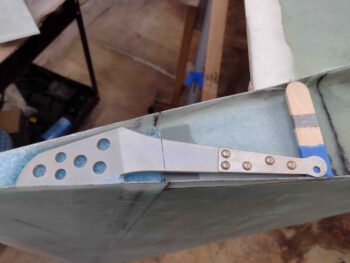
During this initial Bellhorn install configuration, the two main things I was looking at are 1) the positioning fore and aft as I point out above. And 2) the angle of Bellhorn pivot arm in relation to the rudder cable conduit.  The Internal Rudder Bellhorn plans points out that at full rudder deflection, the tip of the Bellhorn pivot arm should be level with the rudder cable conduit inside the wing.
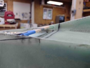
Ah, but there is a bit of twist… or better said, an angle on all this.  Since our winglets are mounted slanted inward a bit, then the Bellhorn arm actually pivots DOWN to then reach and be in line with the opening of the rudder cable conduit.   Clearly with the wing upside down, this means there is a slight upward rotation of the Bellhorn pivot arm.

That’s what I’m looking to achieve here: starting a bit low outboard and moving a bit higher at the end of the inboard swing.  That’s what my two taped popsicle sticks are showing me… the elevation of my pivot swing.
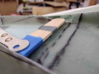
As with all things on these builds, there almost always seems to be a “gotcha!”

Well, mine was that as I was dialing in the configuration of the left rudder Internal Bellhorn with the mounting area in the rudder, as I was sanding down the foam I left the internal rudder walls rough.  At one point when I had done another round of sanding to get the Bellhorn just a tad lower to bring the pivot swing a hair down, I pressed down on the aft end and it crunched through a bit of micro on the sidewall that was keeping it higher than the foam… not a huge difference, but it did result in the Bellhorn tip a bit lower than the rudder cable conduit. Enough that I felt I should add another ply of BID for 3 plies total to the initial layup that the Bellhorn gets floxed into.
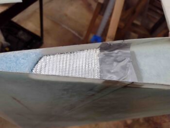
Here we have the Internal Bellhorn initial securing BID layup in the rudder that will allow floxing and “top” glass to secure the Bellhorn in place.  I used fast hardener so it would cure as quick as possible.

I also realized I hadn’t got a shot of Layup #2 after I had razor & Fein saw trimmed away all the excess glass.
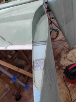
I then floxed in the left rudder Internal Bellhorn and laid up 2 plies of BID over top of it.  I then peel plied the layup and added a taped block with just a bit of weight to make sure the aft end of the floxed Bellhorn mounting arm was pressed as firmly down as possible.
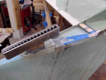
Here is the result a few hours later after I pulled the peel ply.
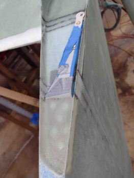
And a broader shot of the floxed in left rudder Internal Bellhorn with 2 plies of BID securing it in place.
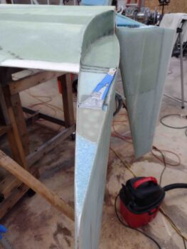
I then spent about an hour and a half making up the ‘A’ Block for the left wing/winglet.
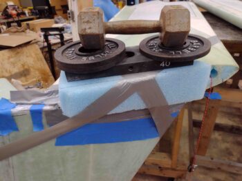
Actually, to be completely accurate I should say I made up 3 ‘A’ Blocks because the first two were fails: #1 being too small right out of the gate, and #2 being good up until I started shaping the inside curve at the forward end… which screwed up the aft side.  I learned to work the front first and then after it was completely dialed in, tweak the back.  Oh, and with a much oversized piece of foam to allow for inside seam movements.

With the left wing/winglet blue foam ‘A’ Block micro’d and weighed in place, I called it a night.
Tomorrow I plan to press forward on getting these winglets installed on the wings!

Chapter 20 – Left winglet Layups 1 & 2

I started out today by ginning up a bunch of blue foam wedges to secure the 8-ply BID Layup #1 in place and keep it pressed up tight and flat against the inside wing glass and inside winglet glass.

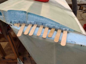
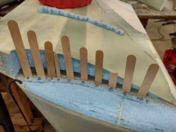
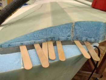
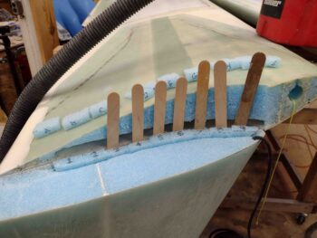
My buddy Dave Berenholtz noted on his on blog that a popsicle stir stick is about the same thickness as 8 plies of BID, so sliding them in place with the wedges gives you a good idea  of the proper thickness required for the foam wedges.

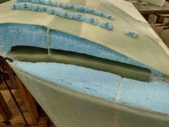
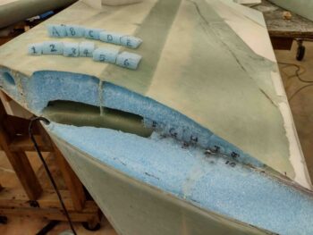
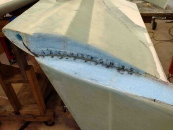
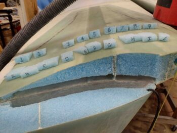
As you can see, I labeled the wing wedges A-J whereas the winglet wedges are labeled 1-9.  You can also see that the fiberglass is prepped for Layup #1.

I then cut and prepregged 4 plies of BID for Layup #1 into 2 different prepreg setups. I also cut all the BID at this point for the right wing Layup #1 as well.

I then wet out the prepregged Layup #1 sets of BID.

I then cut the shear web slit on each prepregged 4-ply BID set and then merged the two sets of prepreg together for the 8-ply Layup #1.

I then laid up the Layup #1 8 plies of BID into the inside corner of the left wing and winglet. As you can see, the slit allows the layup to slide in around the intact shear web.

Here are a couple more angles of Layup #1.

I then slathered up each foam wedge with flox before sliding it into place, starting with the A wedge in the wing, then the 1 wedge in the winglet… alternating up and down, from left to right.

I then left Layup #1 and the floxed wedges to cure for a few hours before I proceeded forward with Layup #2.  Not shown is that I cut the flox corner edges, removed the foam and cleaned up the glass along the glass edges.  I then whipped up flox and filled up the flox edges.  Since I’m using all slow hardener, I want the flox at least slightly cured with as much “body” as possible when I glass Layup #2.  I should note that, per plans, we give the first layup a few hours to start getting into its cure cycle to avoid any exotherms with all the epoxy and flox, but still want an epoxy bond connection between Layup #1 and Layup #2 along the edge of where the wing meets the winglet… kind of at the center of a big X (or + if you prefer!).

Also not shown is that I removed the foam towards the aft end of the winglet (forward of the rudder) to create a channel where the internal bell horn pivot arm will be situated.

About 4 hours later, I cleaned up the protruding foam wedges, wet micro’d the remaining exposed blue foam (about half of it was already covered with flox) and then laid up BID ply 1 and 2 of Layup #2.  These two plies cover farther aft, up to the break between the rudder and the winglet.  They also cover the channel for the internal bellhorn pivot arm.

I also made a small channel in the forward wing end for the antenna cable and ran that through the wing’s foam cable conduit.

Here’s ply 3 of Layup #2 going in while ply 4 is on deck.

For ply 5 and 7 I cut the BID so that the forward portion of the piece had more perpendicular lines (i.e the “wall” or wing edge, etc.) whereas the aft end is a bit angled.  On all the other plies I cut the aft end biased parallel to the weave lines.  Note ply 8 in pic below right.

Also note that for each successive pair of BID plies I stepped the aft edge forward about 1/4″ to allow for a smoother transition when the layup is peel plied.

Here is the left wing/winglet Layup #2 complete… just before I peel plied it.

Again, left wing/winglet Layup #2 complete… just before I peel plied it.

And here we have the left wing/winglet Layup #2 peel plied.

The plans say to wait a few hours to allow the glass to cure a bit before slathering up Layup #2 and the end ‘A’ Block of foam with micro and installing the foam in place.  I’m not doing that for two reasons:  First, I want to ensure my layup looks good, and secondly, I didn’t make up an ‘A’ Block of foam.  I will consider doing that on the right wing… we’ll see.

I then spent a good hour prepping the right wing and winglet for Layup #1 and #2.  I still have to clean all the old epoxy and foam off the exposed glass, and hopefully will get these layups knocked out tomorrow.

It was well after midnight, so I packed it up for the night.  Tomorrow I plan on having another good build day in getting these winglets attached to the wings.

Chapter 20 – Left winglet prep

Today was quite cold and I honestly didn’t get as much done as I had planned, but I did spend a few hours to knock out clearing out the foam and then sanding the wing and winglet inside surfaces in prep for Layup #1, which is an 8-ply BID layup.

Tomorrow I plan to cut and shape my foam wedges first thing and then get the left wing/winglet Layup #1 completed before knocking out the right side.  I also plan on getting layup #2, 8-ply BID layup on the wing end and winglet bottom blue foam.

Chapter 20/23 – Beginning with end goal

Today was all about getting a really good idea on all the upcoming associated configurations regarding the upper winglets, lower winglets, rudders, internal bellhorns and even the Nav/Strobe lights.

I started by getting a grasp of how the lower winglet will attach to the winglet/wing structure.  I know these pics look pretty much the same, but I added in some extra spacers to assess how these lower winglets will integrate.  Note that the lower winglet TE doesn’t exactly align since the lower winglet nose can’t go further forward currently without significantly digging into the blue wing foam.

The key reasons I started with the lower winglets fitting is in determining where the bottom rudder cut line will be, in conjunction with the internal bell horn configuration and fit into the bottom of the rudder.

The High Performance Rudder plans show the angle in the rudder —where the upper and lower winglets meet on the trailing edge— is located at W.L. 18.4.  In maximizing surface area on the winglets and rudders, I set the upper/lower winglet TE dogleg angle at W.L. 18.2… 0.2″ lower than the plans rudder angle break.

Here we have the bottom of the upper winglets marked for cutting at W.L. 18.2, which will be the bottom edge of the respective rudders.

The rudders I’m building are based off of the dimensions Marco derived off of his flying Long-EZ to implement on his project Long-EZ, which will provide almost the same amount of rudder surface area as the High Performance Rudders without using any of the lower winglet or having a kink in the trailing edge of the rudder. See Marco’s write-up here.

Moreover, both the top and bottom rudder lines will be level and parallel to the waterline/longerons vs. perpendicular (90°) to the trailing edge as on a stock Long-EZ [as in the background in pic below].

After I cut and sanded the bottom edge of each winglet/rudder, I measured out and marked up the rudders on the winglets.  Here is the rudder marked out on the right winglet.  My rudder, starting from W.L. 18.2 is 40.2″ high, 8.5″ wide at the base and 4.9″ wide at the top.

Here we have the left winglet with the rudder lines marked, as well as the left lower winglet set into place.

I then got to work cleaning out the foam and cured micro around the rudder cable conduits.  I also trimmed down the rudder cable conduits as deep into the wing as possible with a razor knife.

I then started cleaning out the foam on the left wing for the winglet inside Layup #1.  Yes, I didn’t get very far before heading out to dinner for a little break.

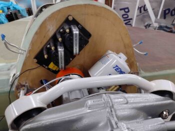
In taking a look at the engine before I headed out to dinner, I noted that the mounting holes for the Electroair electronic ignition’s coil appear to have the coil unit interfering with the SD-8 backup alternator.

After dinner I returned back to the shop with the Electroair coil unit in hand to temp mount it to check its clearance with the SD-8 alternator.  It definitely couldn’t be mounted with the spark plug connections on the lower side, since it couldn’t fit between the SD-8 and firewall.

However, flipped over —with the spark plug connections along the top edge— it fit with just enough clearance (about 0.3″).

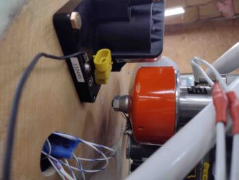
Here’s a side view of the mounted Electroair ignition coil’s clearance with the B&C SD-8 backup alternator.

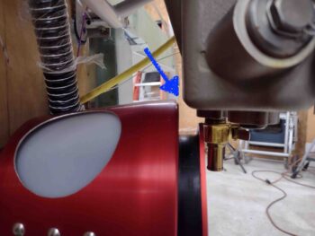
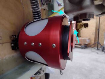
Speaking of tight clearances, here’s the clearance between the top aft edge of RAM air can and the front bottom corner of the engine’s oil pan.  Not much, about 1/4″, but just enough to squeeze everything in!
Lastly, here’s a shot of the aft side RAM air can again, with clearances shown between both the oil pan and also the oil quick drain.  Again, not much… it’s definitely tight but there is just enough clearance (at least so far) for things to fit.

Tomorrow (Friday) the weather is forecasted to be pretty darn cold here in NC.  Thus I plan to finish all the sanding and prep of the wingtips and winglets to allow glassing Layups #1 and #2, which I’ll do on Saturday when it’s much warmer.  If I have time tomorrow I’ll work more engine stuff as well.

Chapter 21/23 – Engine (re)mounted

Today I started off by spending literally almost 3 hours going over the finite details of how I was going to install the winglets and all the associated accessories, mods, plans changes, etc.  As in High Speed Rudders (modified), Internal Rudder Bellhorns (the big questions were here!), layup sequences, etc.

Out in the shop I started out by finally finishing a task on my strake to-do list that I had overlooked: the final 2-ply BID layup on the underside of the left longeron and sidewall bare foam, overlapping onto the underside left strake skin.

Now, this layup is normally a 1-ply BID layup, but since I needed to sand off and remove the original 1-ply layup that bunched up along the seam of the top skin edge and longeron wood and foam, I am replacing that initial layup with yet another ply of BID.  Thus the 2 plies vs just one.

After I laid up the 2-ply BID layup on the underside of the left aft longeron —at the GIB strake opening— I then peel plied the layup.  I’ll note that after I took this pic I cleaned up the layup a little bit.

Since I removed the protective tape over the GIB strake window in the right baggage area, I went ahead and grabbed a shot of that as well.

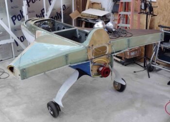
I then prepared the fuselage for the 100-yard trek to the garage to mount the engine by adding in a bunch of weights, about 150 pounds total, in the nose area.

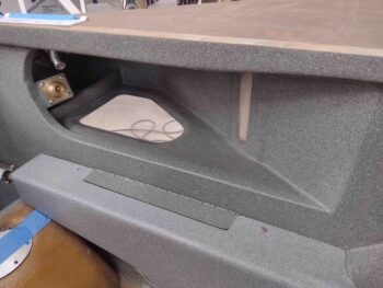
I also taped up (with Jessica’s help) the nose area to allow me to hit the inside surfaces with the gray speckled paint I’m using for the interior nose… since this is one of the last reasonable opportunities I’ll have to do so.

I would have liked a bit more coverage inside, especially under the “nose bridge,” but I couldn’t get the can to fire upside down.  So I did what I could and called it good.  It looks way better than before, so I’m fine with the interior nose paint results.

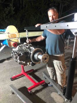
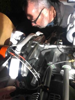
Again with Jessica’s help, I spent over 3 hours moving the fuselage to the garage driveway, setting up work lights (it was dark at this point), flipping the engine back upright, removing the engine from the engine dolly and slinging it from the engine hoist.

At one point we realized the engine hoist just didn’t have enough hydraulic fluid to lift the engine high enough to mount it onto the firewall extrusions, so we had to set the engine down on the wood engine stand I made for hauling the engine down here to NC from N. Virginia.  I then added more hydraulic fluid —which did the trick— and pressed forward with mounting the engine to the firewall engine mount extrusions.

Thankfully after just a little finagling, the holes lined right up and we bolted ‘er on!
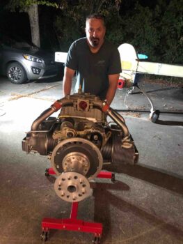
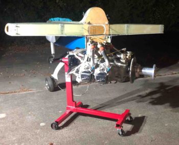
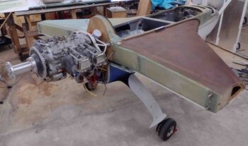
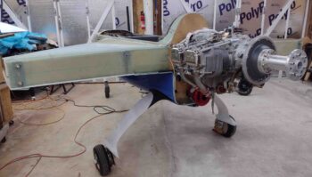
With the engine slung onto the firewall, we then made the trek back to the work shop.  And here she is… many things to do on the engine and of course having it mounted to facilitate the upper cowling install.

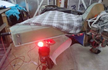
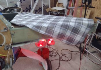
With the engine mounting squared away and the fuselage back in the shop, I then hooked up the heated blanket and set all the heat lamps in place to post cure the left fuel tank as best possible, ala Gary Hunter.

And with a good build day under my belt, I called it a night at a somewhat reasonable hour!  Tomorrow I plan on throwing myself completely into the winglet install prep and internal corner layups.

Chapter 20/21 – Prepping winglet layups

Besides getting the left wing removed and flipped to allow working on the winglet inside corner layups, today was mainly about logistics and prep.

I spent a good 1.5 hours reorganizing the shop and moving the wings, fuselage, carts, large power tools, welders, etc. around to get the wings situated together on one side to allow for glassing.

Here’s a slightly more inclusive view of the entire wings on their new converted taller work platforms, specifically to allow for the wings to lay inverted without the winglets hitting the ground.

I positioned the fuselage in front of the double doors where within the next day or two it will make its trek about 100 yards to the garage to get outfitted with the IOX-340s motor, that will then allow me to ensure proper fit and spacing when I install the upper cowling.

In prep for mounting the engine, I flipped it upside down on its stand to allow the camshaft to get a good bath in oil… since it will probably be the last time the engine is flipped before first flight.

I’ll note that on the way to get outfitted with the engine, I’ll pause the fuselage transit for about 15 minutes and finish shooting the dark gray speckled paint inside the remaining bare areas of the nose.

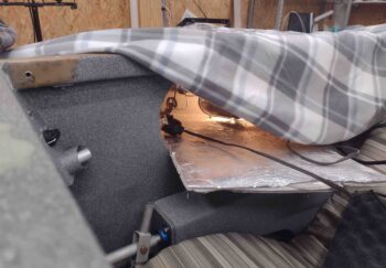
With the wings off, I also took the opportunity to follow Gary Hunter’s advice in post-curing the EZ Poxy tanks with 3 large heat lamps underneath the strake and heated blanket on top.  Gary recommends a minimum of 2-3 hours at 140-150° F.  I don’t honestly know if it’s getting that hot internally inside the tank, but I’ll follow his recommendations regardless.  My 10 second touch test is promising on the bottom, but not so much up on the top strake surface.

I also threw in a couple standard shop lights in the baggage compartment, and one on the outside strake just to keep things as warm as possible.

I’ll post cure the left fuel tank tomorrow, since I was too cheap to buy 2 heated blankets… plus I wanted to concentrate all the heat lamps onto one tank at a time.  I’ll note that I do intend to post cure the entire airplane up to 176° F for the MGS 285 to reach its full strength, so if I miss the mark in getting high enough temps on these interim fuel tank post cures, it won’t be a deal breaker.