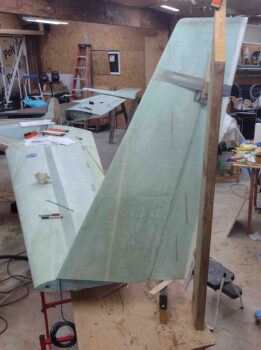
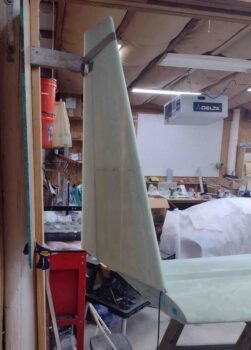
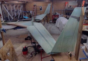
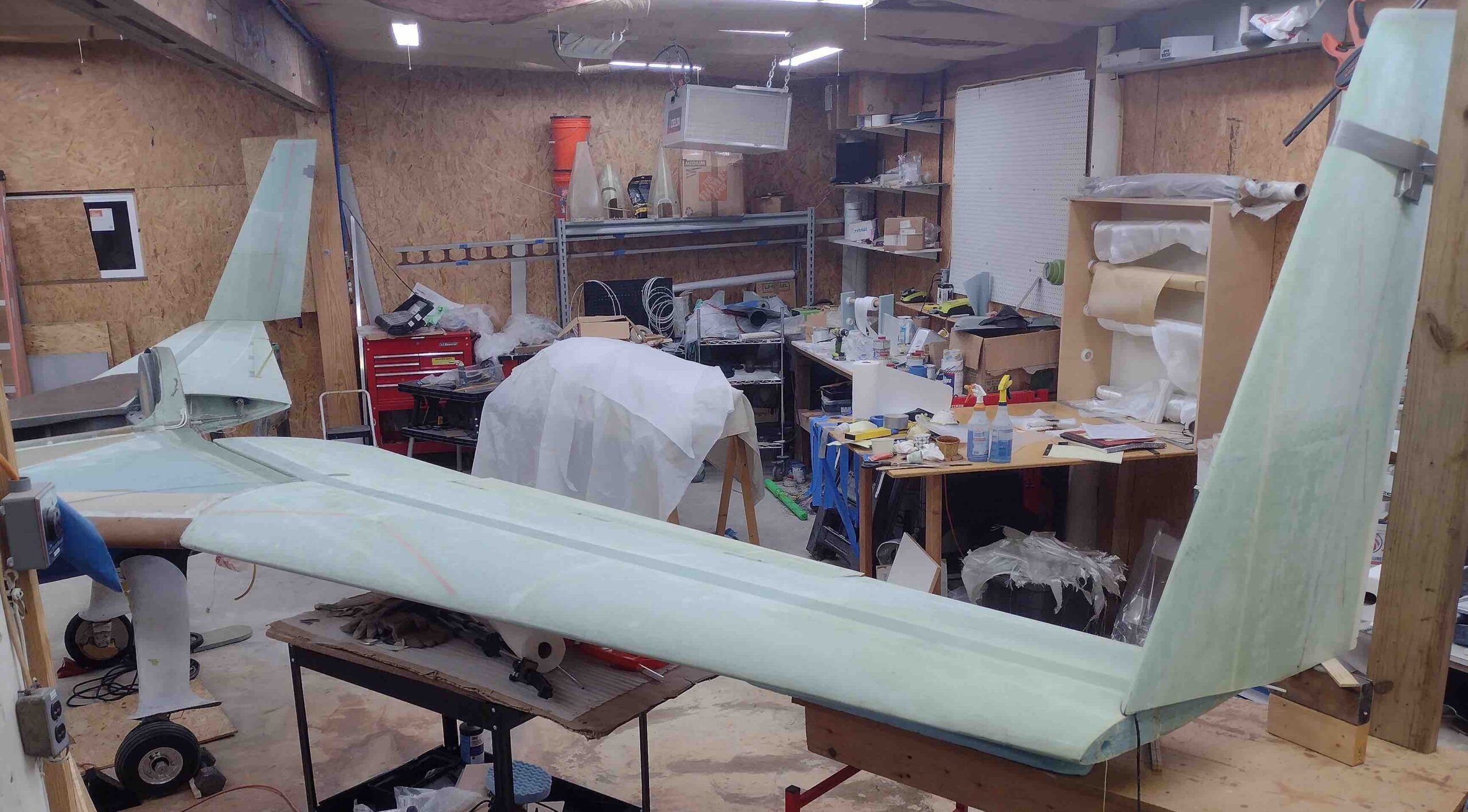
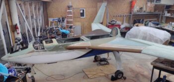
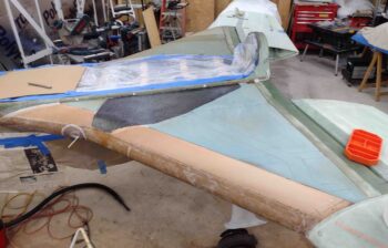
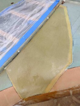
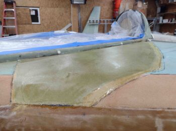
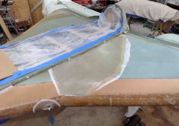
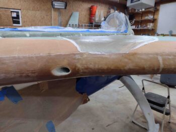
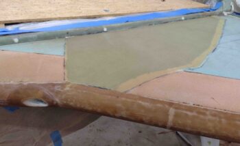
Chapter 20 – Winglets attached

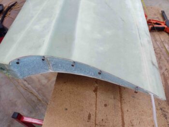
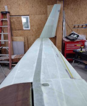
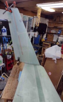
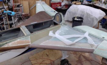
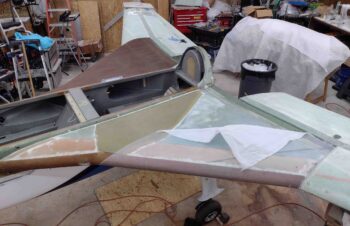
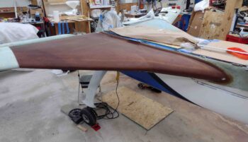
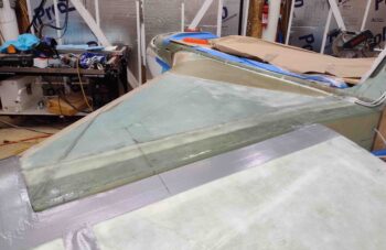
Starting off this morning, I inserted nails into the end of each wing to support the winglets since currently the winglet and wing only contact each other at the edges of their cut lines.

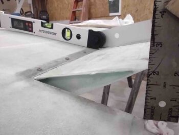
As I remounted the winglets, I of course ensured and verified that the A (102.15″), B (108.35″) and C (118.35″) dimensions were all spot on.

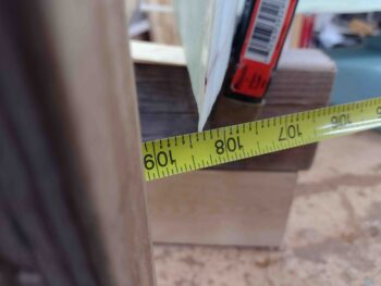
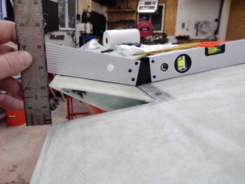
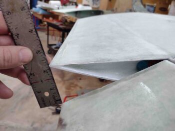
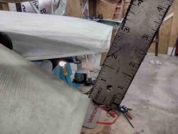
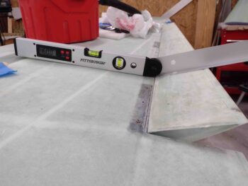
Here we have the “B” dimension on the left winglet.

I will note that after all the machinations to secure the winglets to the wings (hot glue, Bondo, wood pieces, and 3′ stick), on the right winglet my B dimension was at 108.32″, so 0.03″ shy of my 108.35″ target.  As per plans, our tolerance is within 0.05″ so I’m good.  Not of course what I was shooting for or wanted, but the winglet is securely mounted and only about 1/32″ off the mark… I’ll take it.

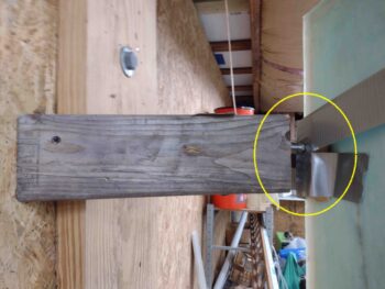
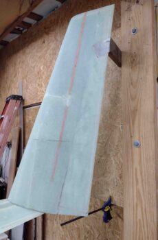
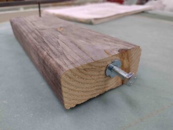
I also grabbed a closer shot of the threaded spacing standoff for the outboard side of the right winglet.

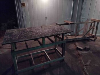
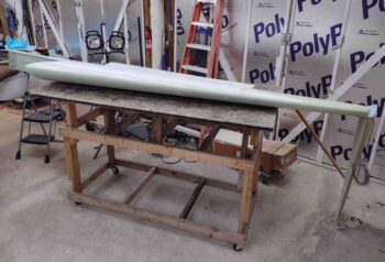
I started working in the late afternoon in an attempt to beat the sun going all the way down to convert the fuselage dolly (below left) and the wing dolly (below right) into dollies that can support the wings, inverted with the winglets attached.  My goal height on these temporary conversions was 50″.

I the rolled right into making a 10 minute project update video that shows the status of the strakes, ailerons and winglets.  My phone was near dead so I used an old video camera that I thought was good, but the video quality turned out not so good.  Anyway, here’s the video:

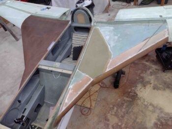
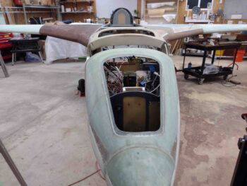
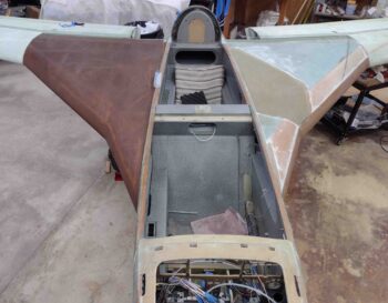
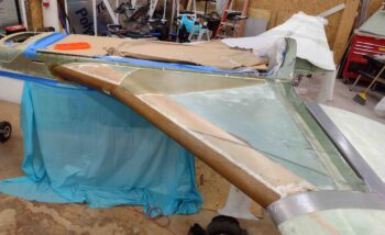
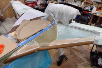
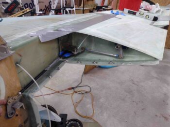
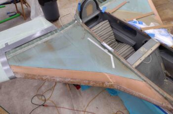
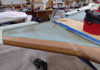
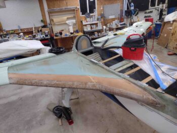
Like I mentioned on the video, a few hours after I shot it my girlfriend Jessica helped me remove the right wing and flip it onto the temporarily heightened fuselage dolly.  As you can see, there is only a couple inches clearance under the top of the inverted winglet.

Tomorrow I plan to get to work on the right winglet in prep for the inside corner layups, but also plan to remove the left wing/winglet and get it onto the heightened/temp converted wing dolly as well.

Chapter 20 – Prepping winglet install

I started out today with placing the winglets on the end of each wing to create jigs to both support the winglets upright and also allow me dial in the A, B, and C dimensions as per the Chapter 20 plans.

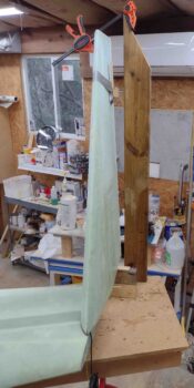
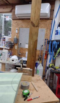
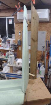
I started on the right side setting the winglet in place to then constructed a temporary jig assembly outboard of it using the center sidewall pillar in the shop.

Note the decimal tape measure locked into the corner of inboard aileron at WPRP.  I had bought some long aluminum channel to use to get repeatable measurements, but for me it was clunky and a pain to manage, and frankly by pulling the tape measure really taut, I’m confident that I’m meeting the plans “within 0.05 inches” tolerance on my A, B, C dimensions.

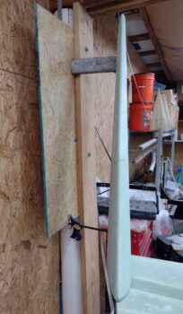
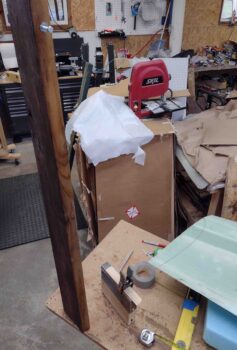
On the right side I screwed a temporary backer board into place onto the center shop pillar that allowed me to attach a clamp on the bottom to support the aft bottom edge of the winglet, as well as cut an angled 2×4 nearly a foot long to support the top outboard side of the winglet.  I simply kept the winglet in place on the top with duct tape.

Once I confirmed that the winglet was in a good general position with the relation to the top 2×4, I then removed the winglet and the 2×4.  I say ‘general position’ since the C dimension between WPRP and very top aft corner of the winglet here is over 120″ where per plans it needs to be 118.35″.  Clearly the winglet top needs to tilt inboard a bit more, and I accounted for that below.

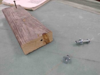
I drilled a hole in the end of my 2×4 winglet support arm and inserted a tap-in threaded standoff.  Clearly by adjusting the 1/4″ bolt I can dial in the C dimension quite easily (more pics on this installed later, below).

I then got to work on setting the winglet jigs up for the left winglet.  This setup is quite a bit different since I have no nearby wall or post to work with, just a work table below the end of the wing (almost as if by design… wink!).

I stacked two 2x4s on edge and screwed them in place as the support for the aft bottom of the winglet.  For the outboard top I screwed a scrap piece of long 2×6 to the table as close to the outboard edge of the winglet as I could get.

I drilled and installed a threaded standoff on the edge of the 2×6 as I did on the right side.  I’ll note that the inboard lean of the winglets to obtain the 118.35″ C dimension required an extra wood spacer or two on each winglet since my standoff bolts were a bit short to do the job all by themselves… a minor inconvenience.

Here’s the left wing trial setup of the winglet mounting jigs and spacers.

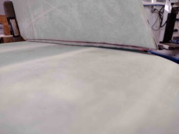
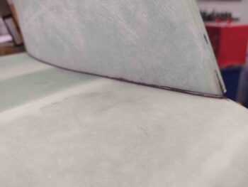
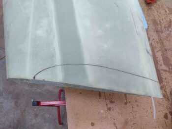
I discovered a very significant issue on both winglets as I was dialing in the A, B and C dimensions… something was afoot with my bottom winglet trim job.  I had followed both the template I had and the plans, but the curve at the very front of the winglet wasn’t sufficient to follow the curve of the top of the wing.  I had a good 0.2″ or so gap at the very front bottom leading edge of each winglet and the wing top.

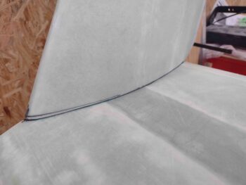
I still set the A, B and C dimensions to ensure I was as close as possible to where I should be with the winglets in place, then laid a fine-tipped Sharpie flat on each wing and marked a contour line onto the bottom inboard edge of each winglet.

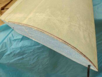
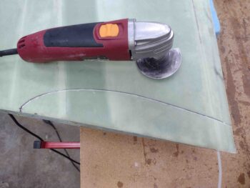
Here I’m re-cutting the left winglet on the newly traced contour line to obtain more of a significant curve on the very front of the winglet.

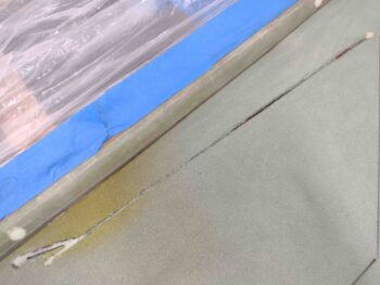
Ahh, much, much better.  It may be hard to tell between all the existing lines and the wonky focus on my “updated” camera app on my phone, but the gap is pretty much gone.

I also re-trimmed the bottom of the right winglet as well, and cleaned up the resulting cut.  I’ll note first that I’m losing about 0.2″ in overall winglet height (no big deal) and that I’m leaving the resulting aft notch at the end of the trim line for now because it makes it really easy when placing the winglet onto the wing to just put this notch up against the wing trailing edge resulting in the front winglet leading edge being really close to the 4.5″ and A dimension lines.

Again, much, much better on fit of the winglet leading edge nose area to the curve of the wing.

I then reset the left winglet in place and, using the jigs, finalized my A, B, and C dimensions.

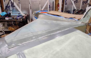
Here’s another shot of the left winglet set in place with the A, B and C dimensions.

I then did the same thing on the right wing end with the right winglet.  Here we have the right winglet set in place with the A, B and C dimensions all dialed in.

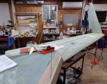
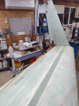
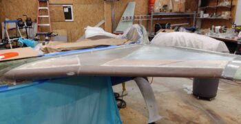
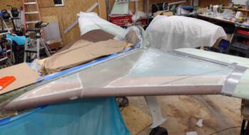
And a few wide angle shots of both winglets with the A, B and C dimensions all set.

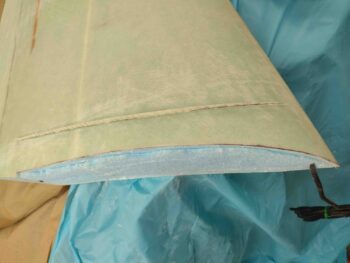
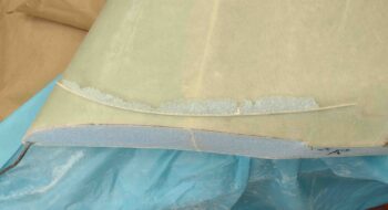
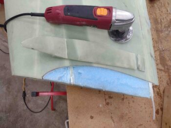
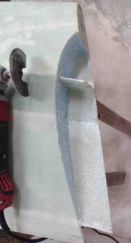
I did a final trace of the inboard winglet outline on the left winglet before cutting out the winglet wingtip notch using my trusty Fein saw.

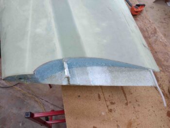
First the top skin and spar cap comes off, then all the foam revealing the leftover shear web.

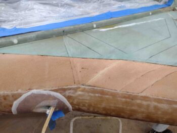
And Voila! the left wing is ready for the left winglet to be set in place for glassing.

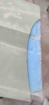
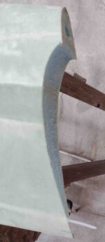
I then did the same thing on the right side.  I trimmed the winglet outline with the Fein saw, removing first the top skin and spar cap, then the foam to reveal the shear web.

I then cut the shear web and bottom skin to finalize the right wing’s winglet notch.

As par usual, it was quite late at this point so I called it a night.  Tomorrow I’ll mount the winglets to the wings with hot glue and bondo.  Then hopefully I’ll get at least one wing removed and flipped over on a workbench in preparation to do the inside winglet layups.

Chapter 16/21 – Aileron Gremlin Attack!

With the MGS epoxy curing on the left strake top layup, I knew I needed to let it cure for AT LEAST 12 hours.  Once I checked the stipple brush and epoxy cup, I knew that I needed at least another 2-3 hours beyond that before pulling the peel ply.

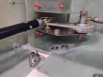
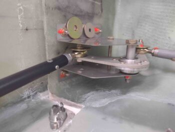
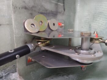
So I started out by installing the recently received AN970-4 wide washer onto the CS126 rod end where it connects to the CS128 bell crank.  Note the temporary standard nut and washer that I removed sitting below.

However, once I installed the AN970-4 washer, I had an issue: my right aileron was pretty much locked in its position, only moving just a hair one way or the other.  Since this was the only real change I made before this issue, I checked this assembly and it looked good.

Upon further assessment, I realized my issue was the AN970-4 wide washer… its diameter is too large and its catching/jamming on the front wall of the open wing root.  Ironically, the washer I had waited to be delivered was the wrong one.  Remember, this whole configuration was based on AN3 bolt installs.  Thus, I simply grabbed an AN970-3 washer and drilled the hole out for an AN4 (1/4″) bolt.

Although I have no pics, I spent over the next 3 hours working on the aileron control system… somehow my CS124 was off its center mark nearly 0.2″ to the left (with ailerons locked at neutral) and my left wing aileron specs were just barely good, where the night before they were looking much better.  Anyway, after slowly dialing in the rod ends on the control tubes I finally got to a decent equilibrium.  Here are my final numbers on the aileron trailing edge gaps:

……………..LEFT           RIGHT
UP:               1.9″             2.2″
DOWN:         2.0″             2.1″

I’ll highlight that these gap numbers are just the end result numbers that quantify the aileron up and down travel. Factors that must be attended to during this entire dance are aileron neutral positions… i.e. you can get the left aileron gaps to let’s say match the right’s exactly, but then at neutral the left and right ailerons are NOT at 0° together.  Also required to be taken under consideration is control stick neutral position and CS128 bell crank hard stops.  The balance act can feel seemingly endless… but I digress.

“Perfect is the enemy of good enough.”

At this point I was ready to start pulling some peel ply off the left strake top layup, but decided to let it cure another half hour while I knocked out cutting the last 3 plies of UNI for the upcoming winglet layups.

Finally we were at a good cure point to start pulling peel ply off the left strake top layups. Here’s the initial few pulls on the inboard side.

Then quite a bit more peel ply coming off . . .

Finally, we have the left strake top glassed and peel ply pulled. I also cleaned up the surrounding tape and the strake leading edge.

Again, both strake tops are glassed.  For all practical purposes Chapter 21 is now complete!

One last pic of the glassed strake tops… on to the winglet installs!

And with that folks . . . yep, I called it a night.

Chapter 21 – My CS spar is gone!!

My strakes are done!  Chapter 21 is complete.

(Yes… minus the fuel cap installs.  Ya got me!)

So, in effect, my CS spar has essentially disappeared into the strake matrix… ha!

I waited 12 hours to allow the right strake top glass to cure before pulling the peel ply.

I wanted to check out how well the peel ply work before I glassed the left side and decided whether or not to peel ply the left side.

I’m happy to report that the peel ply worked great and I will certainly be peel plying the left strake top layups.

I then got to work laying up the UNI plies on the left strake top.

Here we have all the UNI plies, per plans, laid up on the left strake top.

Again, here is the left strake top glassed.  Since I used up pretty much all of the EZ Poxy hardener on the right strake top layups, the left side is getting my normal MGS.  If you’ve taken a look at epoxy prices lately (make sure you’re sitting down!) then you’ll understand why I’m so glad I was able to squeak out a rather large layup as I did on the right side using the leftover hardener I had on hand.

Meaning, yes, I will have different colored strakes until I get to the point of applying micro finishing and then painting these bad boys.  I’m thinking it will be hard to tell what epoxy I used after they are primed and painted <grin>.

Then, as I did on the right side, I peel plied the left side top strake layups.

Here are the left top strake layups peel plied.

And with that, I called it a night!

Chapter 16/19/21- Right strake glassed

Today was huge as far as significant progress on my build.

First, I started by gathering up my front control stick and right side pilot armrest to assess my control stick mounting angle.  Once again, the Cozy Girrrls make extremely high quality parts, but they have the name “Cozy” in their moniker for a reason (or did, as they are now finishing up a Long-EZ).

The Long-EZ plans say to lean the control stick tube in 5° at zero degrees/neutral ailerons and install.  However, with the slick Cozy’ish straddle-stylel control tube that I got from the Cozy Girrrls, it has what looks to be 12-15° slanting control stick mounting nub on the top with ailerons at neutral/0°.
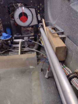
I wanted to get the best angle both for flying comfort and also for left/right clearance both within the armrest, but also with the lower fuselage sidewall at full left aileron, and upper fuselage sidewall at full right aileron.  I decided to go with control aileron tubes pretty much centered which gives me about 12° inboard slant on the control stick.  Not too crazy really when you compare it 5°, and if it really becomes an issue I’ll just pull the control stick assembly, lop off the nub and practice my TIG welding!
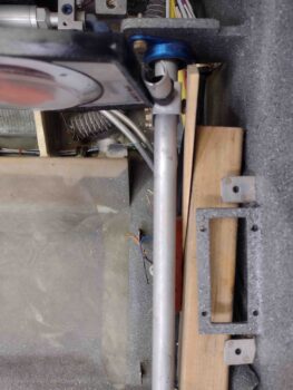
I wanted to also ensure I had at least 1/32″ clearance between the CS124 pivot and the firewall mounted bearing.  This gives me about 1/8″ clearance from rod end bolt heads to current firewall, and with a 1/16″ Fiberfrax going on before the 0.025″ Titanium sheet for final firewall install configuration, I should have plenty of room.
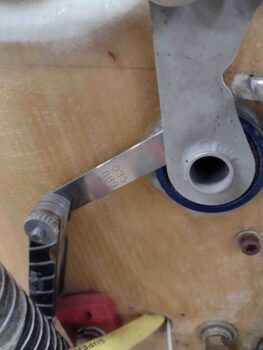
The crazy part of this adventure was getting into the very aptly named Hell Hole… boy did it live up to its namesake today!

As you can (barely) see, the CS121/CS122 pair is buried in the upper right corner.
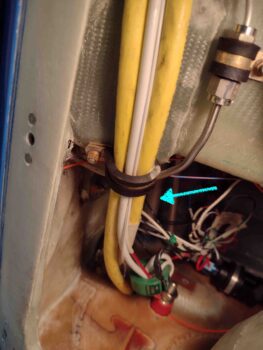
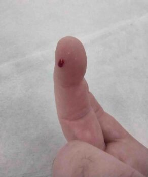
As an aside, I spent a good 15 minutes hunting down and sanding finger killers and vacuuming out the dust to avoid this… which happened mere minutes after ending my hunt for just such offending bits of glass.
I tried in vain for a good 10 minutes to get my 90° tube drill jig up there onto the aileron control tube to drill a nice centered, perpendicular hole… but I didn’t have any clearance to get a clamp up there and I couldn’t get a good seating position to get both hands up there to wrap duct tape.

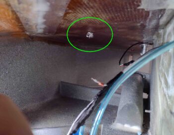
After sitting there for a couple minutes pondering how to make it work, I said “screw it!” and free hand drilled it with a 10″ long #12 drill bit.  After I broke through on the bottom side of the tube I did zip tie a small square to my drill bit to give me a close approximation to what 90° was.
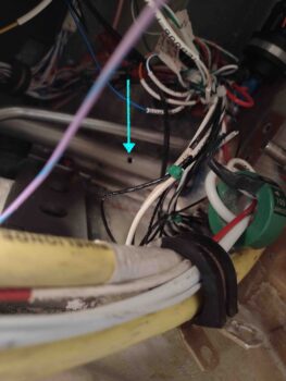
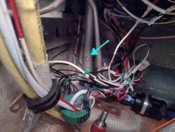
I tried installing the plans called out AN3-11A bolt from the top side of the tube, but we all know the story: there’s just no clearance between the tube and the bottom of the CS spar.  I am out of and had ordered —but not received yet— some AN3-10As so my next bolt in line was an AN3-7A.  Since my install is temporary at this point since the aforementioned firewall components need to get installed, I simply put a standard nut in for the time being.
With my ailerons clamped at zero on the wings, this set my control stick at it’s new zero position as well.
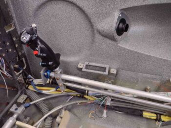
Here’s a top view of the pretty much vertically in line control tubes.
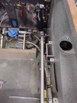
And a shot of the control tubes’ clearance within the armrest with ailerons at neutral.
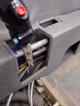
I then moved the control stick full left until the left CS128 bell crank hit the 20° up aileron hard stop.

Bingo!  The aileron is right at 20° up (angle finder is at 160°) and my physical gap is a hair over 2″.  On the opposite right wing, the down aileron gap is over 2.1″, so looking good at the ailerons with full left stick.

And I have way too much room between bottom control stick and sidewall… it reminded me of when you attempt to barter with someone at a market in a foreign country and they accept your first offer.  Doh!  Could’ve been much less!  Well, here, the stick could be over another good 3/8″ providing more leg clearance in the plane… but full right aileron will complete the story.
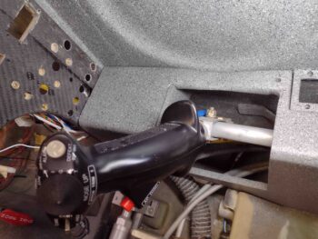
I then did the same exercise to the right: full right stick to the CS128 bell crank hard stop.

My down aileron gap on the opposite left wing is an unusually paltry —for down aileron— 2″.  Good enough, but often we canardians see 2.1-2.4″ down aileron gaps.  The up travel on the right aileron is about 20.4° with a 2.1″ gap between wing and aileron TEs, so I’m definitely ok here.

In fact, it’s probably good that I’m getting a bit over 20° up travel on the right because this is with the stick pegged against the sidewall.  The control stick edge and CS128 bell crank hard stop both physically hit when the control stick just kisses the sidewall.  Obviously during normal flying ops I’ll rarely notice these extremes.

Note how far inboard the bottom of the control stick protrudes just a bit past the armrest.  Not bad at all, but this would be going into either seat cushion or my thigh a little bit.  Whereas the full left aileron exercise would theoretically allow me to move the controls outboard, this is telling me that we’re in a good spot with this exact positioning, all things considering.

I’ll take it!  Task complete.
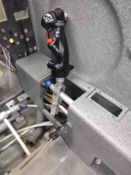
I thought late yesterday that I had received my roll of UNI that I ordered from ACS, but I unwrapped the plastic and paper to reveal it was actually the roll of BID I had added as a late addition to the order the next day. Hmmm?

I checked my email and sure enough, the order with my UNI was out for delivery.  So I took a good hour plus break and grabbed some food before my next endeavor on this build.

Once I got the UNI in hand, I cut Ply #1 for the right strake (sorry, still had the camera in stupid macro mode… ever since they updated my phone without permission the camera works slightly differently!).  This ply of UNI is parallel with the strake leading edge.
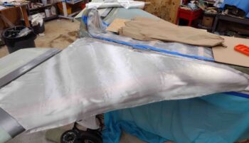
And then ply #2, which runs parallel to aircraft center line.
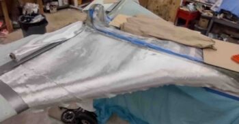
I then prepped the right strake top foam, seams and fillets with EZ Poxy micro and flox. Clearly I applied wet micro to the foam surfaces.  I’m using EZ Poxy here on the right strake top layup to finish up the last bit of E-Z 84B hardener.
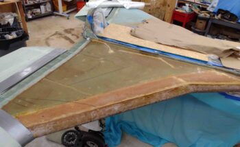
I laid up the first ply of UNI on the strake, with it being a bit more fiddly going on then I remembered with the strake bottom skin layups… but it ended up good.

I then laid up UNI ply #2.
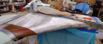
And wetted it out.  EZ Poxy really does have a beautiful look to it when it goes on.
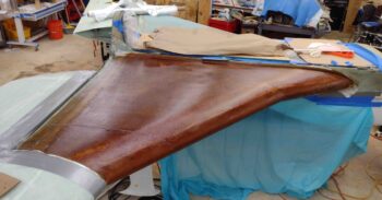
I then added the requisite ply #3, a 5″ diagonal strip of UNI.  I could argue that with my OD rib not in the plans position that this isn’t doing a whole lot for me, but what the hey, it’s one ply of UNI and I threw it on there just in case!
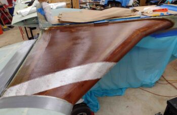
Here we have all the UNI plies laid up on the right strake top.
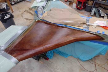
I followed a chapter out of Wayne Hicks’ build, although I don’t remember if he actually went through with it (or maybe it was Bernie Siu… who remembers these things. ha!) by adding peel ply to the entire strake top layup.  I know from the bottom strake surface it took about 2 hours to sand that nasty UNI in prep for micro finishing.
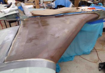
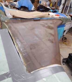
Well, admittedly it took a good hour getting this somewhat wrinkled (it’s been through many moves!!) peel ply applied, wetted out, squeegeed and stippled to remove all the air I could.
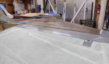
Here we have the strake leading edge with the new top glass overlapping it… which I’ll note that I am pretty darn happy with.
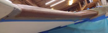
So that is the end of today’s adventure… that not surprisingly went well past midnight by the time I cleaned and tidied up the shop, turned out the lights and locked up.  Time for a glass of red wine!

Chapter 16/19 – Aileron control tubes

This post actually covers the last couple of days.  I started by determining the lengths required of the outboard segments of the CS125 & CS126 aileron control tubes’ quick disconnects.

I cut the right outboard segment of the CS126 aileron control tube quick disconnect.  I then riveted the quick disconnect rod piece into the inboard side of the outboard CS126 segment.

Since I have a 1.25″ wide lower engine mount extrusion vs. the plans 1″ wide engine mount extrusion, which limits the rightward travel of the CS124 firewall aileron control tube pivot, I started installing the aileron control tube on the right side.  I’ll note I had to make a small notch ~1/8″ in CS124 and in the engine mount extrusion ~3/16″ to allow clearance for a decent rightward travel of CS124.  Even with that, I had to offset my CS124 to the left about 0.2″ at 0° ailerons just to get enough total travel to the right.

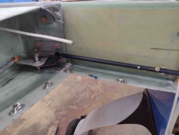
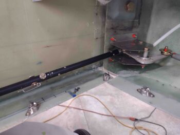
Here we have the CS126 right aileron control tube connected to the CS128 bell crank, hitting the limit stop, with the aileron up travel exactly at 20°… you can’t ask for much better than that!

A wide angle view of what I referenced above: CS126 right aileron control tube connected to the CS128 bell crank, hitting the limit stop, with the aileron up travel at exactly 20°.

I then connected up the left side aileron control tube CS125 to the firewall pivot CS124 and verified that it too was hitting the proper up/down travel angles.  I then drilled out and mounted the quick disconnect pins and —since I prefer an extra margin of safety— AN3 bolts, one for each side quick disconnect assembly.

Here’s a closer view of the left and right aileron control tubes’ quick disconnects.

I’ll note that the reason i’m working the aileron control tubes now is that as soon as the strake tops are glassed I will then pull the ailerons to have full access to the respective WPRP reference points to measure out the winglet critical dimensions to install them on the wings.

I am happy to report that I got my roll of UNI glass delivered late this afternoon.  Tomorrow I plan to first finalize the aileron control rigging by drilling a hole through CS121 & CS122 to connect the ailerons to the control sticks.  Then I plan on glassing at least one, if not both, strake tops to finish those off.

Chapter 19/21 – Right strake prepped

Today I started out by removing the inline resistor on the right fuel site gage LED power wire.  This resistor of course was conveniently located in the right strake baggage compartment.

In trying to grab a shot (next pic below) of the wire, I got this shot with the 3-LED baggage light cluster in focus… so you can see those.

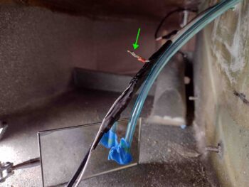
And here’s a shot of the right fuel site gage LED power wire sans resistor.  It was just around the corner of my view and a little difficult to work with, thus why it’s not looking overly clean and spiffy.

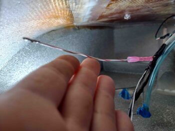
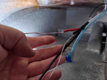
I then used a crimped on connector —which is a rarely used item for me— since it was much easier and faster to reconnect the power wire than soldering would have been.

I then hit the connector with the heat gun prior to adding a length of heat shrink and hitting that with the heat gun as well.

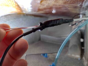
I then wrapped the new connection and other wires in the bundle with electrical tape before securing it with a zip tie.

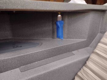
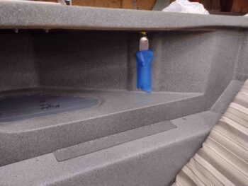
After finishing the wiring for the right fuel site gage and baggage area LEDs, I fired up both sides to compare the lighting of the fuel site gages.  The left side, with its new LED light, is clearly brighter.  That being said, I assessed that the right side is bright enough to meet the requirement of allowing the camera to view the gage during night ops.

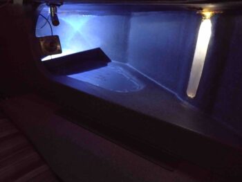
I then grabbed a couple shots of the GIB strake opening showing the lit fuel site gage and baggage area.

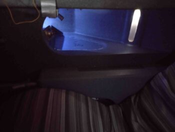
And a shot of the lit right baggage area from the front side pilot’s seat.

After my final test of the right fuel site gage LED and baggage area LED lights, I buried the wiring on the top side of the strake in the foam channels.  I’ll note that I did add in a resistor on the top side wire leg going to the 3-LED baggage lights.

I also scuffed up the cured flox/micro in the small holes that secure the GIB map light.

I then micro’d up the channels to bury the wires and also the small holes for the GIB map light.  I then peel plied all the micro.

I used the leftover micro from burying the wires on the topside strake wire channels to apply it to the right strake LE root pilot fresh air vent inlet.  I’ll clean that up and assess next steps in conjunction with glassing the strake top.

I then sanded the top of the right CS spar and all the areas I missed previously to finalize the prep of the right strake top for glassing.  I then taped up the surrounding wing edges to protect them from any errant epoxy or flox/micro contamination.

And with that folks, I called it a night.  Tomorrow I’ll be focusing primarily on installing the CS 125 and CS126 aileron control tubes to finish up the firewall aft aileron control installation.

Chapter 21/22 – Right strake top prep

I started out today by sanding the right strake’s leading edge and top foam core in prep for glassing.

On the right I did have one significant problem area, towards the middle with a slight hump… either way, I’m sorry to report I think I’m going to need a good thick layer of micro in this area to fill in the slight depression towards the aft side of this marked area, between it and the foam top seam with the CS spar.

Here’s the right strake pretty much ready for glassing.  Note that I sanded down the existing peel plied cured strake leading edge.  I also Dremeled the dead flox off, and dulled the rest, on the long seam between the foam core’s aft edge and the CS spar.  I also dulled up the blob of flox around the exiting fuel vents as well as the fuel vent probe wire channel and square probe flange.

Finally, I spent a good 15 minutes cleaning up the small air intake scoop for the pilot fresh air vent at the root of the strake leading edge where it meets the fuselage.  I’ll add a round of micro to this and clean it up before final glass to assess further if I need to add glass or just clean it up a bit more.

I then drilled a hole near the right fuel site gage and well forward of that to route the fuel site gage’s LED power wires.  I then cut the wires and routed them through the holes… after I created a wire channel on the strake top surface.

I then drilled another hole and added another leg to the fuel site gage LED power wire to tie into that wire setup to power a trio of LEDs for the baggage area lighting.

However, just like on the left side when I hooked up the circuit I got no LED lighting on the right side fuel site gage (I think I errantly thought I had tested the circuit on the left side, but apparently did not).

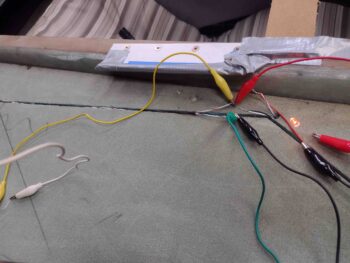
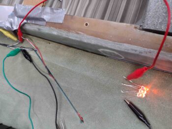
I then hooked up battery power directly to the right fuel site LED on its own with no other connection and got this:

I then tried adding in the 3 LED lights for the baggage compartment and the fuel site gage LED went out.  Hmmm, interesting.

I then grabbed a new spare orange LED and hooked it up in place of the fuel site gage LED… it worked in addition to the added 3 LED lights.

That led me to think that the fuel site gage LED has an internal resistor that I didn’t know about, and is prohibiting enough juice to get through to light it up.  I have a 470-Ohm resistor in line in the circuit that powers the site gage LED light, so I took a chance on blowing the LED but to test my theory I then hooked it up to the battery without any (external) inline resistor.  It fired up fine and stayed good for about the 10 minutes I had it on.  This confirms to me that Vance constructed these with internal resistors.  Add another resistor it seems to be fine, but then add more of a load and it’s just not seeing enough current to light up.

I then did a quick think and some quick mental math… and concluded that my parallel circuit vs a series circuit is probably causing the issue.  I then hooked up 3 of the orange LEDs in series and connected them to power.

Yep, I got the LED light on the fuel site gage to light… however, it’s not very bright.

I pulled off the protective tape to see if I could see any “glow” or not… and, well, or not would be the answer Bob.

I then turned out all the shop lights and it did have a glow, but I have to tell you this is a lot brighter in the pic below than what I actually saw… it’s fairly dim.

Thus, I’m heavily considering doing pretty much the same on the right fuel site gage as I did on the left side: mount an external LED just above the clear fuel bubble.

I’ll work this LED issue tomorrow… it’s getting quite late here.

On another topic, I will note that I got back from the birthday party in the early evening.  I immediately hung the taped aileron control tubes with long screws to the wing dolly outside.  I then hit both aileron control tubes (CS125 & CS126) with a couple coats of clear coat.  Here they are a good few hours later:

The clear coat actually cured a little grayish, but as long as they withstand normal wear & tear abuse and resist corrosion, I am good with that.

And with that, I called it a night.

Chapter 16/19/20 – UNI Report Card

It was a light build day since I had a bunch of errands to do today plus get ready for a birthday party tomorrow.

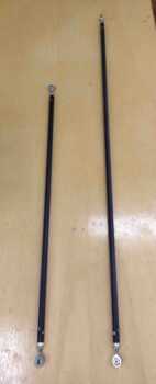
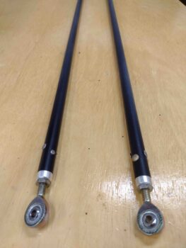
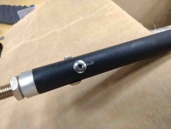
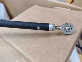
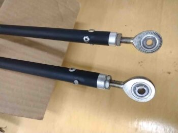
I did break out the control tubes to touch up some paint on a few significant scratches I made while installing the rivets.  Here’s just a couple of examples of the scratched paint.

Although I want the control tubes looking as spiffy as possible, within reason, my overarching concern is corrosion.  I picked up some flat black enamel last night that will allow me to simply brush the paint onto the damaged areas without everything else getting obliterated with black paint as well, as it would with a spray can.

Here are some of the previously scratched/damaged areas of the control tubes now touched up with black, a few hours after I painted them.  Tomorrow, after a good night’s cure, I’ll tape up the rod-ends and then clear coat the black paint on the control tubes.

My next task was continuing on in my quest to get as many winglet-securing UNI plies of glass cut out of my scrap bin as possible.  I also finished off the remainder of the UNI roll since I have a good bit coming this Wednesday, mainly for the strake top layups.

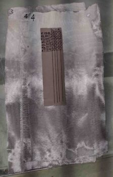
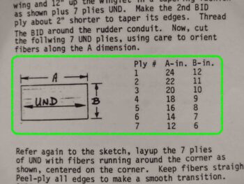
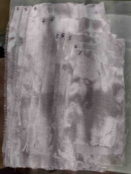
Here’s the winglets’ UNI ply schedule as spelled out in the plans:

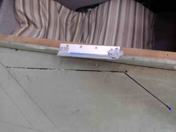
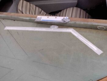
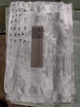
And here’s my UNI plies count for the winglet UNI schedule, above.  As it stands, I only need 3 plies to have all the UNI cut and ready for laying up to secure the winglets to the wings.  My next task will be to review and possibly cut the BID plies required for these layups as well.

After I finished up this blog post and published it on my website, I then reviewed the plans for the winglet installation on the end of each wing.  I was focusing on the point that the plans use as the epicenter for all the dimensions , which is the inboard/forward corner of each wing’s aileron cutout: WPRP.

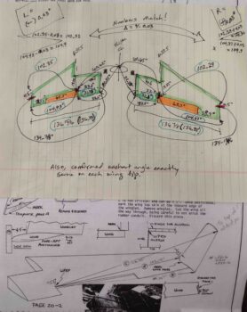
My concern was that I knew my wings weren’t exactly equal in length and moreover, that there was a slight difference in the distance inboard from the wing root edge where the ailerons start (1/8″ to be exact).  Yep, this was not going to allow me to sleep, so well after midnight I opened up the shop, fired up all the lights and started measuring every dimension on the wings and ailerons I could get my hands on [twice, just to make sure my numbers were right].  These convoluted chicken scratchings are what I came up with:

So buckle up buttercup and put your thinking cap on!

FINDING: My left wing is nearly 1/16″ longer than the right, actually 0.06″ to be exact. And this is proven out In nearly every dimension measurement I took.  Interestingly, the most egregious error I have is that the wing TE is 31.98″ from wing root corner to aileron cutout on the left wing, and 32.1″ on the right wing: 0.12″ off, or again, 1/8″.

However, go forward to WPRP and measure straight to the wing root edge (~5.75″ forward of TE), and both wings are at exactly 33.1″.  In fact, in each wing’s inboard square “box” between WPRP, the corner of the BL 55.5 wing notch (end of CS spar), the inboard forward wing root corner, and the inboard aft corner of the wing root edge, nearly every dimension is exactly the same between left and right wing.  This means that my ailerons inboard edge are most likely at a very slightly different angle to each other combined with my wing to aileron gap slightly different as well…. something is going on at the inboard aileron TE since the WPRP ‘epicenters’ are pretty much in the exact same spot on each wing.

As per the Chapter 20 plans, I then marked a line on each wingtip that determines each winglet’s LE when setting the winglets on the wing and also determining the winglet cutout at the end of each wing (see bottom part of pic above).  This line is 4.5″ aft of the wing LE.  From there, I checked the bottom 2 critical measurements as basically outlined in the plans: WPRP to the 4.5″ line, and WPRP to the outboard TE corner,  Again, these dimensions confirmed that my left wing is exactly 0.06″ longer than the right… at least from WPRP to the winglets.

My initial thought at 0100 in the morning was that I had two (2) options:
A) Simply mark and sand down the left wingtip 0.06″, or
B) Simply divide the difference in half and add it to the short (right) wing and subtract it from the long (left) wing.  Problem solved.

But back in the house, after taking another good look at the plans, I realized that the plans “A” dimension (WPRP to the 4.5″ line) of 102.15″ was shorter than both my left (102.35″) and right (102.29″) wings “A” dimensions.  I was merely lopping off everything outboard of 102.15″ so who gives a hoot if the forward 4.5″ of my left wingtip is 1/16″ longer than the right wing?  Do you think anybody will notice?  Will it affect drag? haha (Sorry Burt, should’ve trusted you!)

Finally, I will note that I used my level to confirm that the washout angle at each wingtip matched each other perfectly… which gave me even more confidence that I should be good with my strake-to-wing interfaces as I do the final glassing on the strakes.

Tomorrow I plan on getting back to work sanding and shaping the right strake top in prep for glassing.  I will also attempt to get the right fuel site gage LED light wires run “above ground” and install the right baggage area 3-LED light cluster as well.

Chapter 20/21/22 – Left strake layups

This morning I started off by a myriad of cycles of climbing in and out of the backseat to test and mount a small white LED light externally above the left fuel site gage.  Although it is a bit brighter than it was before, it fits the requirement and doesn’t look bad at all.  I 5-minute glued the LED in place and then covered it with Gorilla duct tape.  I then covered the black Gorilla duct tape with a strip of blue painters tape I saved that is covered with the granite gray cabin paint.  Not a perfect match, but you’d really have to be looking hard to see my little slight of hand.

I’m calling this task complete and pressing forward.

On the strake top I added dry flox to the ends of the wire channels where there was a hole entering into the baggage compartment below.  In the rest of the channel I used much wetter flox.  I’m using flox on the left side just to add strength any way I can in reinforcing this area where some passengers may be climbing in and out of the plane.  On the right side I’ll use micro.

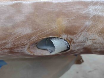
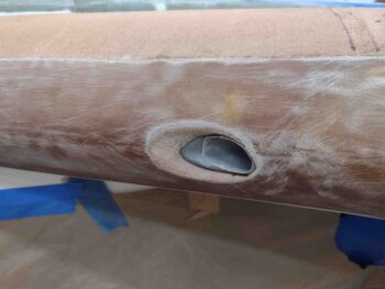
As the flox in the wire channels (above) cured, I then got to the task of trimming the extruding oil heat RAM air scoop on the front of the left strake’s leading edge.  I had just started to take the Fein saw to it after I marked it when I thought I should grab a final shot of it.

I trimmed the actual RAM air scoop protruding out, then I sanded down & contoured the LE foam and glass surrounding the scoop entrance.

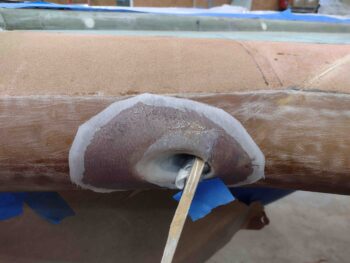
I the laid up a ply of BID around the RAM air scoop LE exterior on the contoured foam to just inside the opening of the scoop.  The outboard side has a much tighter radius curve to navigate, so I stuffed a wad of duct tape around a paper towel to keep the glass and peel ply tight.  In one spot I clearly needed another wedge so I used a taped stir stick to keep it all tight.

I then used the leftover epoxy from the RAM air scoop layup to whip up some micro and finish filling in the wire channels for both the fuel site gage and baggage area LED lights . . .

and also the fuel probe wire channel.

Note in the pic below, if you look closely you can spot just a dot of blue painters tape in the center of the fuel probe floxed square.  This is where my strake foam core sanding exposed the top of the center probe of the fuel probe.  Since I’m laying down more electrically conductive carbon fiber as my first ply, I covered the top of the fuel probe with a very small dab of tape to keep the fuel probe electrically separated from the carbon fiber.

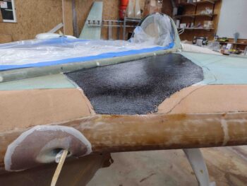
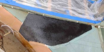
I then wet micro’d the foam and laid up my last big piece of carbon fiber BID I have left.

Here we have a wide angle shot of the left strake reinforcement ply of carbon fiber laid up. Again, this strengthens the left side strake for ingress and egress of passengers.  I would actually prefer they go in by stepping on the pilot’s seat and swinging their leg over into the back seat, but I know not everyone will be able to do that… so it’s all about GIB comfort. <for some builders… ha!>

I then added and wetted out a ply of Kevlar atop and overlapping the ply of carbon fiber.

I’ll admit there’s a slight element of risk here not in safety or function, but in possibly subjecting myself to future pain in this build if my surface elevation of these plies are not in line with the rest of the strake when it comes time for the final UNI layups… or even the micro finish.

Nonetheless, I like these plies being “sub-surface” and replacing a scant bit of surface foam vs. being added on top and definitely being dealt with during the micro-finishing process.  Again, I like Kevlar over the more brittle carbon fiber, but Kevlar as a top coat to be sanded and micro’d is not something to be trifled with… it gets fuzzy when sanded.

I then peel plied the Kevlar top ply of the left strake reinforcement layup.

I’ll note that I used fast hardener to layup these strake reinforcement plies to allow me to then layup the top UNI plies and finish off the left strake glassing tonight.

The same thing for the RAM air scoop.  While the reinforcement plies cured, I then pulled the peel ply from the cured RAM air scoop layup and cleaned it up.  Not bad.  I’ll put some “makeup” on it with micro to refine its looks later on, but the bottom line is that it’s functional, doesn’t look horrific, and most importantly: done!
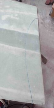
While my reinforcement plies cured, I ran out to Lowe’s hardware to grab some stuff from their aviation department.  And grabbed a quick bite to eat.

Upon my return the carbon fiber/Kevlar reinforcement layup had cured.  I set about sanding the top of the left side CS spar, the outboard left longeron and the fuselage where the strake leading edge merges with it.  I also cleaned up the existing leading edge glass in prep for added glass.

So after about 45 minutes of prep and a little extra cure time, I pulled the peel ply on the carbon fiber/Kevlar reinforcement plies.  Not to brag, but very thankfully this layup turned out very nicely.  It’s nice and smooth and the edge levels intersect very well with the surrounding foam.  There should be minimal contour issues with micro later on, and laying up the strake top skin plies of UNI.

Speaking of UNI top skins… which I was fully prepared to knock out this evening.  Uh, funny thing with that: I don’t have enough.  Somewhere I simply lost track of how much I had on the roll (which is hard to tell, it always looks like a lot) and I only had enough for one full ply and a lot of the second ply… but not all.

With one good ply on hand (out of 4), I spent the next couple of hours going through my UNI scrap bin and cutting pieces for the upcoming installs of the winglets.

When I got to a point where I had a good handle on my required vs actual UNI stock, I then called it a night and went inside to place an after-midnight order with Aircraft Spruce for another 14 yards (a fair bit extra added) of UNI.  And because I didn’t realize how much BID actually goes onto the winglet layups, I ordered another 6 yards just for that.