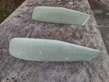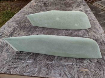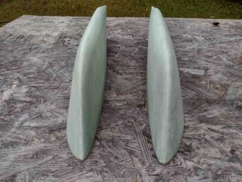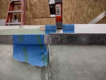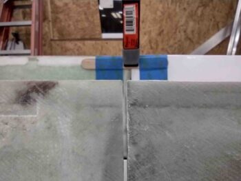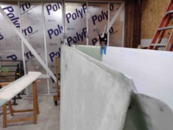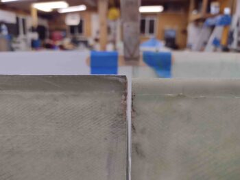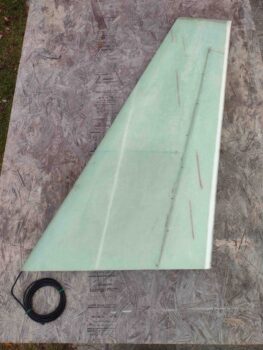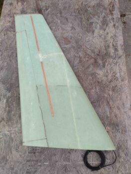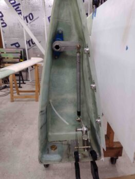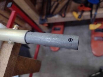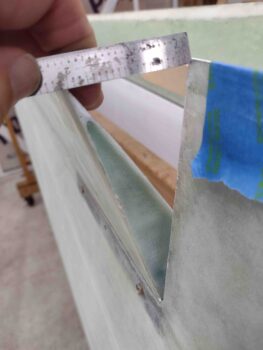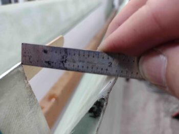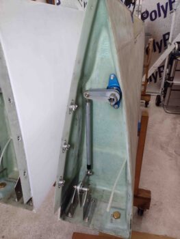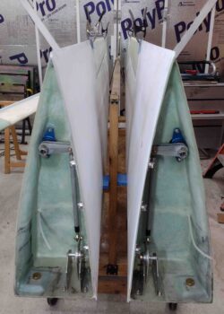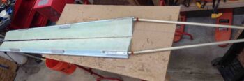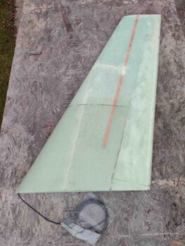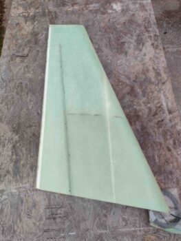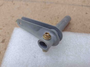
Chapter 21/22 – Left strake glass prep

After refining my sequential task list, I got to work in the shop about noon.

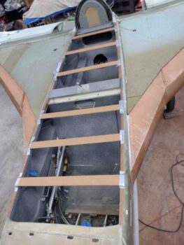
My first task was to cover up the center open area of the cockpit with plastic to protect the finished cabin area from dust and errant epoxy, micro, etc.  I found these thick strips of cardboard used as space filler in a foam box from ACS, so I trimmed some to length with scissors and taped them across the longerons somewhat as joists.
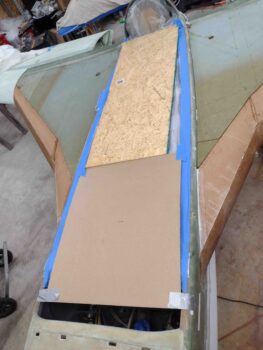
I then covered the cockpit from longeron to longeron with plastic.  Then made myself some work surfaces with both a piece of plywood and thick cardboard.
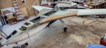
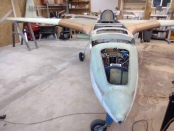
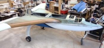
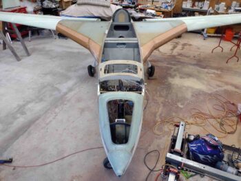
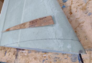
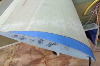
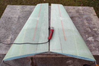
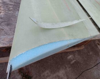
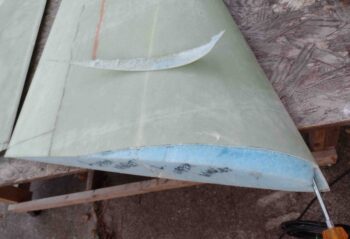
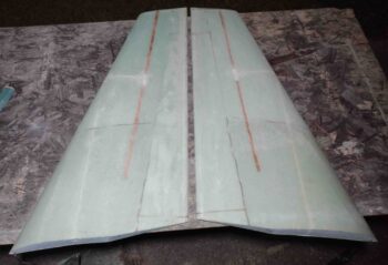
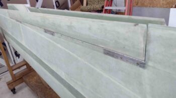
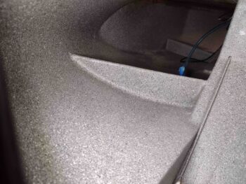
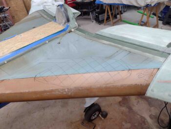
I then started sanding and shaping the left strake top and leading edge.  The hashed area below was the area that gave me the most trouble.  My R45 rib seems just a tad high on the top side thus the top (blue) and leading edge (tan) foam cores needed a bit more thinning in this area to get the strake surfaces smooth and even.
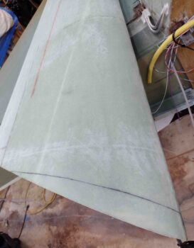
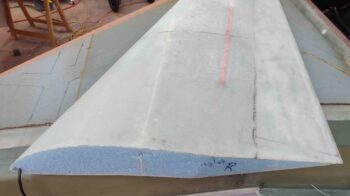
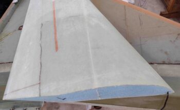
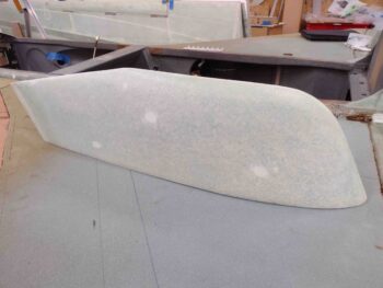
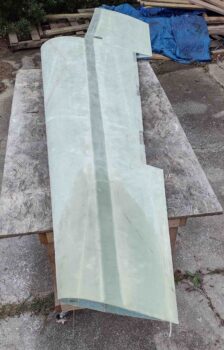
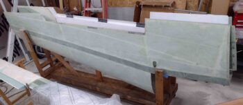
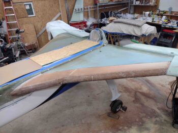
Here’s the left strake top and leading edge foam sanded, shaped and ready for glassing.  I still need to prep the flox seam along the CS spar and sand the CS spar itself.
As per my usual weirdness, I had gone back and forth on wether or not I wanted the inboard left strake reinforcement plies to be on top where nearly all builders add them, or underneath the 2 large plies of UNI covering the strake.  Well, since I wanted carbon fiber for the rigidity and stiffness, but like to protect bare CF with Kevlar for the puncture resistance and added strength, I decide to “bury” it by adding it first on the strake, then laying up the 2 plies of UNI over it.

I cut out the last remaining piece of UNI BID I had (thus the weird shape that was NOT the original planned shape…) and a covering piece of Kevlar as a second ply to “protect” the CF.  With my known dimensions of the CF and Kevlar, I then laid them out on the strake top and marked their perimeters, then sanded a very slight depression for both plies into the top foam of the left strake.
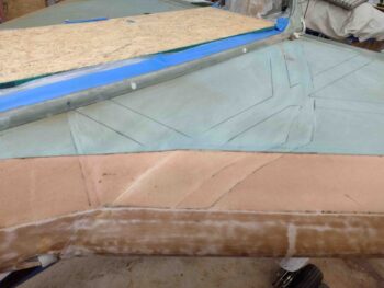
Before I laid up the carbon fiber and Kevlar reinforcement plies, I needed to get even a little weirder.  As anyone who has followed my build for more than a week knows, I like to kill the proverbial multiple birds with one stone. So a build task I needed to address was this one below:  How do I secure the fuel site gage LED wires to the underside top/roof of the baggage compartment?
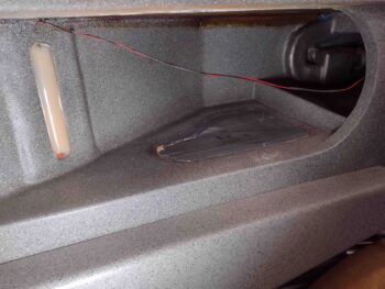
Well, I remember noting recently, paraphrasing another builder IIRC, to essentially always try to use gravity as your friend.  And recalling my very efficient Dad who was always about “working smarter, not harder,”  I decided to do both and simply drill a hole right near the fuel site gage up through the top strake and another one well forward of that and simply run the wire through a small channel in the foam (see below) laying atop the inside skin of the baggage compartment rather then wasting way more time in the painful and messy task of pinning these wires up to the top surfaces of the baggage compartment.

“NO FREE LUNCH” as my college economics professor used to love to retort… regarding the money supply system.  But here I’m not going to open up a channel on the top of the strake without getting some extra benefit for my effort.  Thus in my pondering this endeavor, I decided it would be a perfect time to add some strake baggage area lights and tie them into the single LED light on the fuel site gage… since these LEDs use so little current.  Yes, this was obviously a little bit of an afterthought, but better now in my opinion while it was somewhat easier to do than later trying to reach into the bowels of the strake baggage compartments… especially if I was trying to tie into existing power wires.

I had ordered a bunch of loose LEDs a long time ago and had them sitting around, so after 10 minutes of trial and error R&D I decided I liked one bright white LED combined with 2 blue LEDs.  I wired them in parallel just in case any decided to die (unlikely) they would all be getting their own respective power feeds.  Here’s the initial soldering of red and black wires to the LED leads.
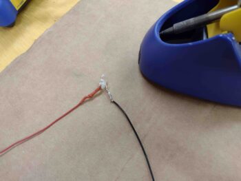
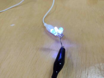
And a pic of the configuration: white LED in the middle with a blue LED on each side.
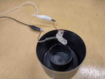
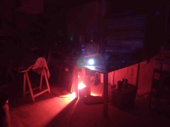
Here’s a test with all the lights off… except my impromptu heat lamp “heat box” for the E-Z Poxy hardeners.  Not bad light output for 3 LEDs, and definitely plenty in my thinking for the baggage area.
Here’s the right strake baggage LED lights initial ops test.  With the shop lights on, and from the side, you can see the blue-white-blue configuration.
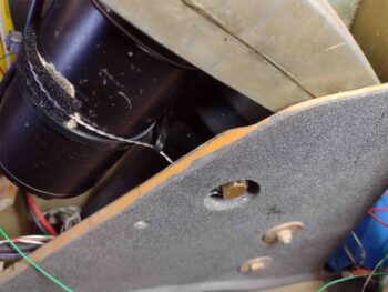
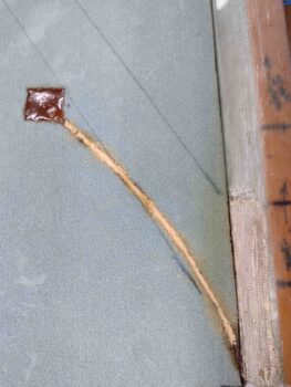
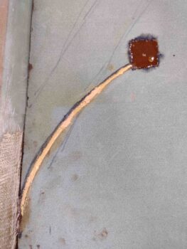
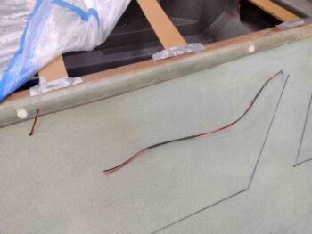
Here we have the initial holes drilled front and aft, with the cut fuel site gage LED wires run into each hole at each end.  I cut the LED wires closer to the front side since this is where I’ll tie in the baggage compartment 3-LED bundled lights I made up above.
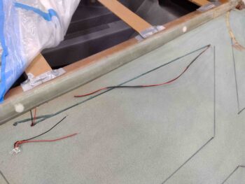
Which you can see I made a small branch off the main wire channel with a hole that the 3-LED bundle fits into deep inside the baggage compartment up against the original fuselage sidewall.
My test for the added baggage compartment blue/white LED light cluster was a smashing success IMO… here’s a shot of the front side strake opening into the baggage compartment (pilot’s seat).
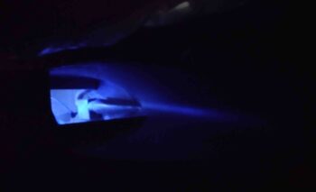
And from the rear, with a bit more white light since the LED cluster is situated behind the oil heat RAM air duct/bridge…. which is exactly what I wanted.  More actual light for the back seater to see into the baggage area.

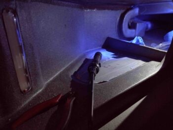
However, after testing this a number of times I hit a snag.  As you can see in this pic below, my fuel site gage LED light is inop.  I was concerned about this since the wire leads on the site gage’s LED were so fragile and brittle they kept breaking off.  When I soldered the wires to this left fuel site gage there was at most a 1/4″ of lLED lead wires showing, and honestly well shorter than that.

No matter what I tried, I wasn’t getting the LED inside the fuel site gage to power up, which is a real bummer because I was extremely pleased on how those turned out.  Plus, having lit fuel site gages is important since I want to be able to see them on the EFIS camera I have pointing on each site gage.
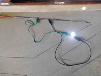
To ensure I was getting power to the fuel site gage LED, and that my soldered splices were good, I stripped away a bit of the outer wire sheathing in 2 separate spots to expose some bare wire and tied in another LED to it.  It fired up which tells me power to the fuel site gage LED is fine.  It’s my connection to it right at its stubby leads that is the most likely culprit.
It was pretty darn late at this point… my happy success was now facing a good bit of PITA tasks to remedy this new curveball.  I hadn’t really eaten all day and Jess was sweet enough to come over and cook me a late dinner while I struggled to figure out my fuel site gage LED woes.  I called it a night and will pick up with this endeavor tomorrow.
Chapter 13/19/21 – Wings (re)mounted

This morning I started out by finishing up a task I actually started a couple of days ago: safety wiring the pivot bolts on the Wilhemson nose gear actuator.  Marc Zeitlin has pointed out that he has seen many times during canard pre-buy inspections that these bolts are dangerously loose and could allow the nose gear to collapse, etc. if one or both fall out.

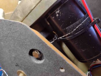
To counter this issue, I swapped the bolts out to ones that have holes in the bolt head and then safety wired the bolts. Another factor here is that these bolts actually pivot back and forth just a hair as the nose gear goes in/up and out/down.

For this reason, and also not to cause harm to the actuator motor, I left the safety wire just a tad loose and then cinched up the slack with a zip tie.  Near each bolt head I drilled holes into the NG30 at a steep angle going forward and angled in to avoid the 1/4″ aluminum mounting plates: another reason why I didn’t just wire these bolts together going straight across was not having the stainless steel wires tight against (read: sawing) the edges of the 1/4″ mounting plates.

Finally note that I put a strip of velcro along the actuator motor housing to offer it a little padding against the safety wire.  I may refine my methodology as time goes by, but this of course will be assessed every year during the condition inspection.

I then got busy cleaning, sweeping and organizing the shop in prep for mounting the wings onto the spar/strakes.  I measured the wings and then took a bunch of measurements to figure out the best position for the fuselage in my shop to allow me at least a couple feet of space at the end of each wing to work on winglets once those go on.  I then moved the fuselage into position at an angle in prep for re-mounting the wings.

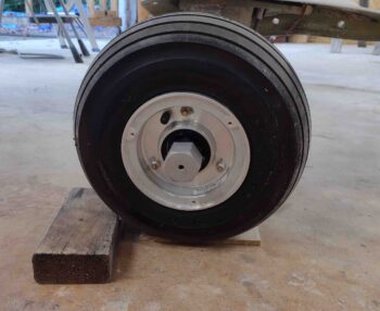
I then filled up the main gear tires to 80 psi before I leveled out the fuselage, spar and strakes by trying out a few different pieces of wood before finding the correct thickness under the left wheel.  Getting everything leveled prior to the wings going on would then allow me to use Waiter’s (IFlyEZ.com) method in determining how the wings’ incidences compare to each other.

With my girlfriend Jessica’s help, I then mounted first the left wing, then a little while later the right.

Now, I actually took all these pics after I checked both wings angle of incidence compared to each other (see below) and think I still had the camera on “macro” when I took a bunch of the following pics… thus, forgive some of the haziness.

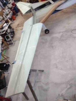
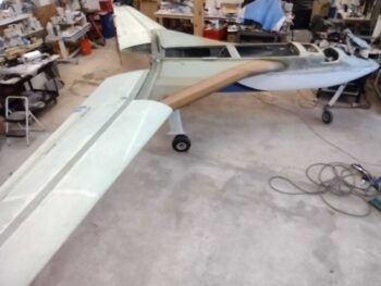
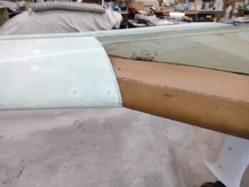
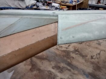
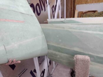
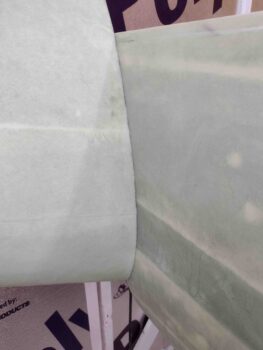
Here’s how the wing-to-strake intersections look currently on each side.

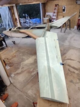
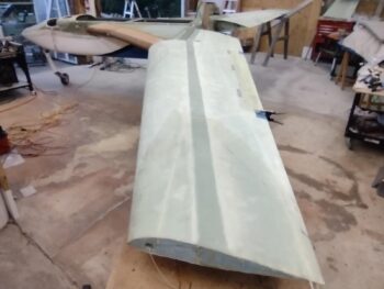
And just a bunch more shots of the wings mounted.

And a bunch with a bit more of the strakes showing . . .

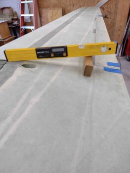
Again, following Waiter’s method (with minor changes due to level length) I set my level up on the BL 55.5 line with the level resting on the wing at the corner of the spar cap and the BL 55.5 front wing jut-out.  I then get the bubble centered by using a block of wood . . .

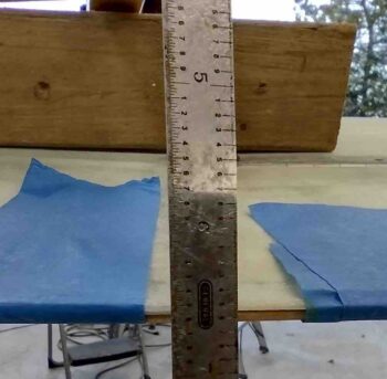
I then measure from the top aft corner of the level down to the top edge of the wing’s trailing edge.  On the right wing this came out to be 6.5″ almost exactly on the nose.

Now, one measurement doesn’t tell you anything because we are comparing the respective wing incidences to each other.  Clearly by ensuring the level has the bubble centered on each side, if one wing has a different incidence angle than the measurement from the aft top level corner to the trailing edge would be different than the other side.

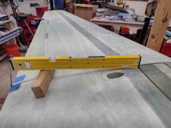
Here I have the level set up, bubble centered, on the left wing.

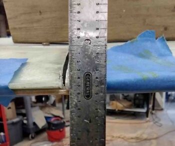
And the measurement I got was on the second big line in the middle between 6.4 and 6.5 inches, closer to 6.46″ I’d call it at the top edge of the wing’s trailing edge.  But if we call it 6.45 then we’re still within 0.05″ of the right wing.  Clearly this could be a difference in thickness of the spar cap, the TE, a very slight incident level, etc.  But I’m going to call a delta of 0.05″ or less very good… and this will let me press forward with confidence in shaping each top strake to each wing knowing that the wings’ incidence angles are very close.

Although I don’t remember the numbers, I will note I did this same process when the wings were inverted and also got very good results.

With both of my wing’s angle of incidence being so close to each other, I called it a night and took Jessica to dinner…. today was definitely another milestone in the build worth celebrating!

Chapter 14/19 – New Wing Bolt Brackets

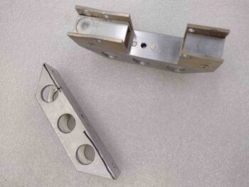
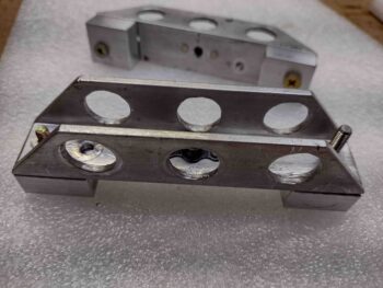
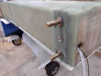
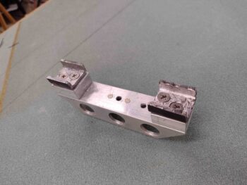
Today was all about upgrading the outboard wing bolt brackets with 4130 steel U-channels to ensure that the bolt heads will always be secured in place inside the channel.  This did NOT happen with my last two (2) versions of the aluminum bolt brackets since —when push came to shove— the bolt head pushing on the U-channel bracket definitely shoved it aside as you can see in the top center of the pic below.

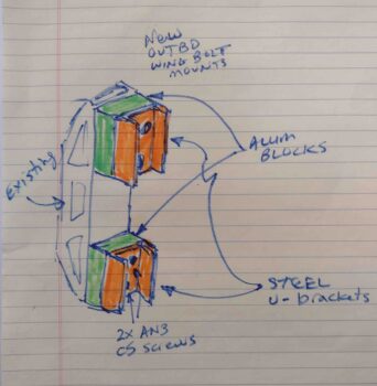
Here’s my proposed design that I came up with shortly after the second flipping of the bird, where once again I caught the shoulder —right where the threads end— of one of the four outboard wing bolts as I was tightening the nut, having failed to put that one extra washer on there.  It turned out to be a good thing because it proved that wing bolt bracket version 2 was not up to the task of retaining the bolt head under more intense pressure.  Clearly in my configuration I needed to use steel where the bracket contacts & secures the bolt head from spinning.

Here I got through dismantling the first bracket when I thought I would grab a pic of what I’m on about… note that I had mounted AN3 cross bolts to try to keep this exact issue from happening, without success.

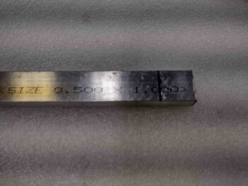
After referring to my proposed design for the MOD 3 brackets, I first rounded up some 1″ wide by 1/2″ thick 6061 aluminum stock.

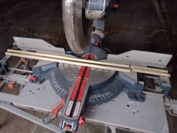
Not looking for anything overly fancy, and wanting to get these things done ASAP, I simply used my large chop saw to cut 4 squares off the 6061 bar stock to be used as spacers.

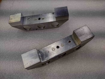
I then set the freshly cut 1″ x 1″ spacers into place on the bridge pieces where they will get mounted.  I’ll remind you that I need a “bridge” since I have an internal cable conduit from the internal bulkhead outboard in each side of the spar that I need to work around… literally.

I then clamped the 1″ x 1″ x 1/2″ 6061 spacer blocks into place and drilled the screw holes closest to the top and bottom edges of the bridge brackets… these holes are getting reused while the second hole on each side will have to be re-drilled since the U-channels are significantly smaller at 1″ x 1″ than the ones on the version 2 bolt brackets.  This is mainly for weight savings since the new U-channels will be 4130 steel.

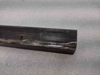
Now, the 1″ x 1″ x 1/8″ 4130 steel square tubing stock I have on hand was one of the 2 original pieces I had ordered thinking I would use them for all the engine mount extrusions (yes, being quite the odd duck I used one 4130 extrusion on the top left corner).  To make 90° angled extrusions I attempted to “rip” these square tubing pieces on my table saw with a cutoff wheel installed.  The problem was that the cut off wheel would flex under pressure so I wasn’t getting a straight cut….

Thus I punted, only went with one 4130 steel engine mount extrusion and dumped this piece in the spare metal bin.

To ensure I have as much strength as possible on my U-channel brackets, I wanted to fill these ground down corners back in with steel before pressing forward… so out came the TIG welder.

I have to say, for not having TIG welded in well over a year I was pretty happy with the results.  Here’s one side below.

And each opposite corner weld after I ground them down and cleaned them up.

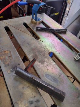
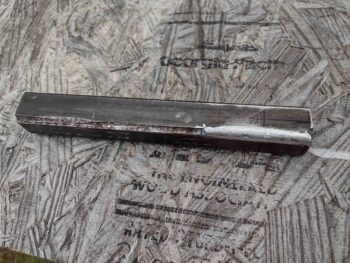
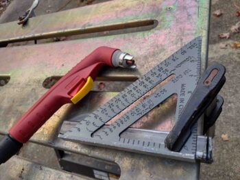
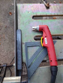
After some sanding and acetone I then set about to cut out the actual U-channels from my now freshly reinforced 4130 square tubing.  I didn’t want to mess around with getting the plasma cutting table cleaned up, water added, software updated, etc, etc. so I simply hooked up the hand cutter, made my marks and pulled the trigger (ahem… literally!).

I started by cutting the end to clean it up… a “facing” plasma cut, if you will.

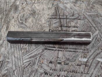
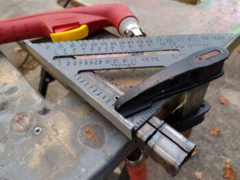
I then needed to rip both sides, 180° apart on opposite faces, to get the edge cuts for the U-channels.  My estimation for the plasma kerf and standoff to center was off a hair, so one set of U-channel brackets came out about 1/8″ deeper than the others.  No big deal really since they are the same relative to each other in their respective pairs.

You can see the difference in U-channel depths from my miscalculated “ripping” above in this pic below.  Here I’m doing the cross cuts to actually cut off the first set of brackets.

After 7 more cuts I had 2 pairs of 1″ x 1″ 4130 steel U-channel brackets, again with one set (right side) about an 1/8″ deeper than the other pair.

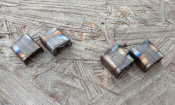
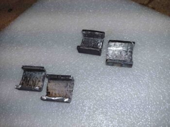
The plasma cutting process left some slag on the inside surfaces of the brackets.  This combined with the original inside dimensions of the 4130 square tubing being just a bit less than the width of a 1/2″ wing bolt head, I needed to do some cleaning up and trimming internally on these freshly plasma-cut wing bolt brackets.

The insides aren’t pretty by any measure, but they will certainly work to test this MOD 3 design proof of concept and secure the wing bolts until I get around to making some final nice ones on the milling machine, etc.

I then spent a good little bit of time aligning, clamping and drilling out the screw holes and internal countersinks for the countersunk screws I used —note in the opposite direction of version 2 brackets.  Again, I reused both the very top and bottom holes near each end, but had to drill completely new second inboard holes through the “bridge,” aluminum spacers and steel U-channel brackets.

Here’s the first MOD 3 bracket completed….

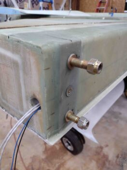
which I installed into the left side spar.

And here’s the second MOD 3 wing bolt bracket finished.

Which I then installed into the right side CS spar.  With this one the center securing screw is just at the edge of the nutplate inside, so next time I install this bracket I’ll grab a next size larger screw to use.

I’m calling these new brackets a success.  I will say that I was planning on getting the shop organized, moving stuff around including angling the fuselage to mount the wings… but it was later in the evening, I was just plain beat from a long day and Jess was making dinner.  So with today’s mission complete I called it a night.

Chapter 16/19 – MM-4 rod ends in place

Besides finishing up and tweaking yesterday’s post, I did a fair amount of research today on upcoming tasks.

I also received the MM-4 1/4″ rod ends a day earlier than expected.  I went ahead and mounted an MM-4 on the end of the left wing aileron control tube, CS125.

I then did the same on the right side, installing an MM-4 rod end on the end of CS126 aileron control tube.

In the wing roots, I installed the MM-4 rod ends, tested the aileron geometry good before then drilling and riveting the rod end inserts into place on the end of the left and right CS129s.

Note that I also marked a considerably number of the hardware with orange torque seal.

I also pulled out my TIG welder and a bunch of welding accessories in prep to welding the wing bolt bracket U-channels tomorrow.  I may need more nitrogen shielding gas so will deal with getting some more of that if required.
 

Chapter 16/20 – Winglets get trimmed!

After returning back later this afternoon from my quick overnight trip to Raleigh, NC, I got to work sanding the left bottom winglet to allow for attachment and micro finishing.  I had missed a couple of spots on the right bottom winglet that I touched up as well.

Here’s a front head-on view of the bottom winglets.

My next sanding task I intend to knock out this week are the wheel paints.

I need two things before I mount the wings back onto the bird: 1) Rework the internal CS spar wing bolt brackets for the outboard pair of bolts.  This is the wing bolt mod that a lot of EZ owners/builders do that have the wing bolts captured internally sticking out of the spar facing aft to make it EZ to put the wings on… especially with just one person.  Most bubbas use a low-profile piece of aluminum U-channel, but since I have to have a “bridge” to get over the internal cable conduit, I’m going to need a couple of 1″ square coupons of steel U-channel.  That will requite some TIG welding.  More to follow on that, which I plan to focus on tomorrow.
Item #2 is the MM-4/HM-4 rod ends that I need for the CS128 aileron control tube bell crank that came with 1/4″ bolt holes (I’ll note all the other components had 3/16″ bolt holes).  When I mount the wings I want to test out the aileron travel on each side and be ready to knock out linking up the entire firewall-aft aileron control system.

With delivery from ACS set for Tuesday, that gives me the next day and a half to get the welding knocked out before the MM-4s go in.  I plan on having the wings on Tuesday night, and start shaping the top strake skins Wednesday.  Then planning on having top strake skin layups complete by this coming weekend.

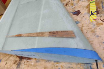
My next task after the strake top skins are glassed is mounting the winglets to the wings.  Not wanting to jump into the welding fray tonight, I finally decided to figure out the winglet lower template and get the bottom edge of the winglets trimmed in prep for mounting to the wings.

My first task was to find and mark the centerline of the upper winglets leading edge (no pics).

The next step per plans is to use the paper template from the plans and glue it to the inboard side, as explicitly stated in Chapter 20 of the plans.  I had grabbed a copy from a build buddy that has a real set of plans, since mine are the PDF version.  In my ignorance and naivety back in Germany early on in this build, I thought it was a template like all the others (canard, elevators, etc) so I put it on a piece of 1/4″ thick plywood.  Probably a good thing in the end since it survived all these years!

Now, in assessing this entire template fitting deal, my buddy Dave Berenholtz discovered that the template fit a lot better on the flatter outboard side of the winglet… obviously counter to what the plans say.  And we all know there are errors in these plans… they are not infallible.  Since I was using my wood template to make up blue tape template “appliqués” I decided to test Dave’s method as well as follow the plans.

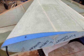
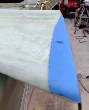
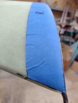
OVERVIEW: If you set the pair of winglets upright in front of you looking at the leading edges, you would have 2 left sides and 2 right sides.  If you broke down, say the left sides (in relationship to sitting in the plane), one would be the inboard of the right winglet and the outboard of the left winglet.  Since I do everything exactly as Burt says to (haha!) my primary focus is on the inboard edge (plans method).  Thus as per my example I labeled my blue tape template “R” for the inboard right winglet (“primary”), but also used it on the outboard LEFT winglet (“secondary”).  Clear as mud?

Using my example above for the other side, the LEFT blue tape template above is applied to the right winglet’s outboard side (secondary).  I then marked the edge of the tape template and carefully removed it.

I then used the same LEFT template for its primary purpose, marking the left winglet’s inboard lower edge (primary).  After the tape template was in place I then marked the cut line and removed the tape.

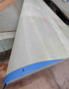
Here we have pretty much my initial example in action.  The RIGHT blue tape template is applied to the outboard edge (secondary) of the left winglet… I then marked it and removed the tape (no pic).

I then used the same RIGHT blue tape template and applied it to the inboard edge (primary) of the right winglet (note the leading edge centerline marks)….

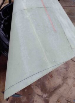
And marked the edge of the blue tape template onto the winglet with a narrow point Sharpie before removing the template.

Well . . . I could stair at these lines and wonder if they were right or not, or in my bull in a china shop fashion I could just cut the damn things.  As Tony Stark so aptly states in the Iron Man movie, “sometimes you gotta run before you can crawl!” … ha!

It was early evening and since it’s Fall here we lose daylight much faster now.  If I was going to cut these things today it had to be sooner vs later (unless I wanted a messy shop!).

Here we have the marked pair of winglets, ready to trim the bottom edges to allow them to fit the wing tips.

I put flat tip screwdrivers over the RG-58 radio antenna cables (shows you how long ago I started this project… I would have used RG-400 had I built these 6 months later than I did) to protect them.

I then used my ever-trusty Fein saw to trim the inboard cut line just below and inside the line on the right winglet.  With a little coaxing (pardon the pun) I removed the glass skin piece.

And then did the same thing on the left winglet.

I then slowly —in 3 phases— used my Fein saw to cut down into the foam, perpendicular to the cut line.  The real focus here is that inside line since the outboard side doesn’t have to be exact since it hangs out into air and doesn’t mate with anything other than the Block ‘A’ piece of foam and eventually the lower winglet… both trimmed to fit the outside edge, not vice versa.  Which is why I’ll note that the plans state, “Mark the trim line then saw the piece out (coping saw) sawing roughly perpendicular to the mark.”

Once all the foam was removed to the other/inboard side, I used a long 1/8″ drill bit to drill just slightly below (aka towards the original bottom winglet edge) the foam’s new rough contoured shape.  I then flipped the winglets over and drew the line along the top edge of drilled holes also using the marked template line as a general guide for the shape.  I then cut the outboard sides of the winglet bottom edges, before using a narrow sanding block to clean up the new bottom winglet surface.

I’ll note that my resulting outboard cut line was about 3/16″ below the cut line of the outboard template, on both sides.  This tells me that using Dave’s method works fine (it obviously did for him!) with just around a negligible 3/16″ less height on the winglets… in my armchair engineering assessment!

Here are some shots in the lit shop of the freshly trimmed right and left winglet bottom surfaces.

I did a quick check of the right winglet on the end of the right wing to see how my cut line came out.

Pretty spot on considering I haven’t even really cleaned it up or sanded it smooth yet!

Now that my curiosity was abated on the lower winglet template fitment, I then propelled myself into another issue that I find somewhat perplexing with the build process on these birds.

BACKGROUND: LPC #131 in CP 49 is a mandatory ground plans change that mandates using 4130 steel control tubes for the ailerons aft of the firewall.  As an aside, I know some Long-EZs that are still running aluminum and that is a risk assessment we all must make. To be clear, I say that with zero judgement. Since I will have a titanium wing root cover plate I personally decided to go with aluminum CS129s inside the wing root, but where my control tubes are exposed I went with 4130 steel in line with this CP change.

But wait, there’s more.

LPC #131 specifically addresses replacing aluminum components that are less than 0.1″ thick.  That’s why the aluminum CS128 bell crank and CS131 spacer are still used since they meet this requirement.  CP 50 provided further clarification on this plans change and gave more specifics for its implementation, including using “four (4) stainless steel pop rivets, such as Cherry #CCP-42.”

I will note that this last statement is easier said than accomplished in the real world.  I’ll also note —let me be clear that I AM NOT FRAGGING ANYONE!— that I still see a lot of folks with steel control rods and solid aluminum rivets… which I’ll point out are 1/8″ diameter so should technically meet the 0.1″ LPC #131 requirement, if it weren’t for the CP 50 SS pop rivet comment.

I will again state that I have no dog in this fight.  I am not a deputized member of the Canard Police Force that tells everyone how their stuff is not per plans and to proclaim 50 “hail Burt’s” for redemption…. I ask because I’m curious or will say something if it looks really dangerous. My notations and questions are ones of interest and curiosity.

Now, as any good military officer will do during Operational Planning, I’ve framed the problem as I see it.  If any of you have any other info or methods, please feel free to give me a shout.

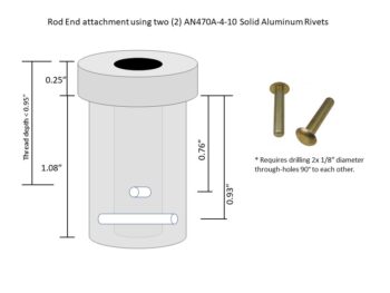
Here is my take on how we use solid aluminum rivets to mount a Rod End insert into the end of a control tube… EZ/PZ:

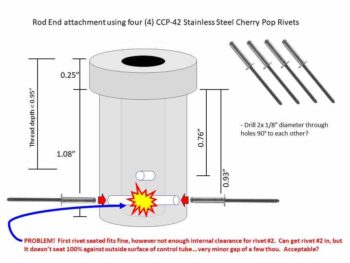
CP 50 states to use four (4) cherry pop rivets, #CCP-42s.  Ok, but hold the phone Bucko!  There is an inherent clearance issue here (remember, this is even before we went to 1/4″ rod end inserts!) in that one drilled through-hole with pop rivets going in at 180° out from each other has the first one going in fine, but the second one —although it will go in— does not seat 100% against the surface of the control tube.  Is this acceptable?  I guess that’s a personal choice. In my book not as a standard practice for every rod end getting installed.

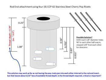
So how about if we offset every hole for all 4 pop rivets getting installed?  Well, we need 1/8″ between the holes (and with the way pop rivets flair internally that’s even a minimal clearance spacing… it’s tight).  Ok, so check this out.  Note how we eat up our available depth to thread the rod end into the insert.

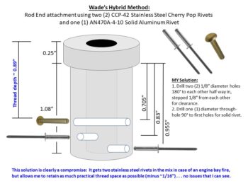
I’ve learned that in negotiations that compromise is actually the least beneficial to both parties… but here in the technical world I think it worked out ok.  This is my method of dealing with this internal clearance/crash issue with the pop rivets… I simply did a personal risk assessment and pressed forward.

I’m using two stainless steel cherry pop rivets (CCP-42) and one solid aluminum rivet.  As I note in the graphic below, that gives me 2x non-melting securing points in case of an engine fire… and let’s be honest, those are not an overly common event.  I place this in the realm of remote possibilities, but let’s still be prudent and as safe as possible.  Right?

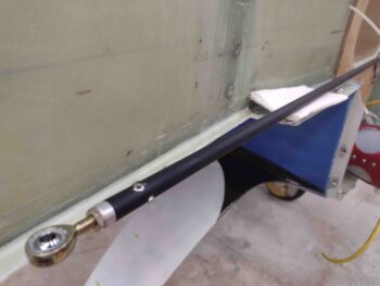
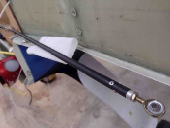
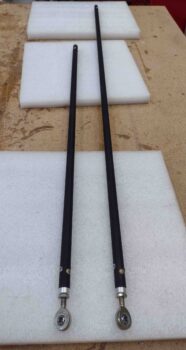
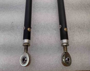
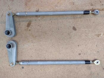
Here are my aileron control tubes —CS 125 & CS126— painted black with the rod end inserts riveted into place as per my hybrid method.  I’ll note that these are way longer than required and will be trimmed to length at final install, and the quick disconnect components installed to allow for EZ wing removal.

The firewall side ends have XM-3s installed since the CS124 pivot tab has holes drilled for AN3 bolts.

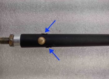
Here we have a side shot of the rivets securing the rod end insert.  Note the solid aluminum rivet facing the camera, perpendicular/90° to the stainless steel pop rivets that, while 180° apart from each other, are also stepped 1/8″ away from each other . . .  as is the aluminum rivet from the SS ones.

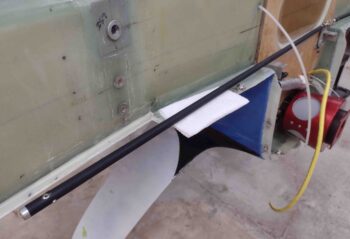
Here’s the longer left SC125 control tube test-fitted in place.

As well as the shorter right CS126 control tube test-fitted in place.

And both control tube rod ends secured to the CS124 pivot tab with AN3 hardware and wide area washers.

Knowing I had a fairly lengthy task of getting all these explanations and examples in this blog, I called it a night!


Chapter 16/19/20 – A bit o’ stuff done

I started out today by swapping out the temporary nuts on the bolts securing the CS127 brackets to the aircraft grade nuts to make the install permanent.

I then knocked out a seemingly sideline task of aligning the trailing edge of the ailerons with the trailing edge of the wing… that seem to get askew once the aileron is cut out of the wing and remounted,

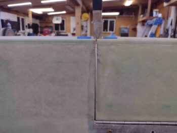
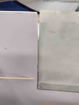
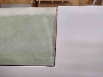
Here’s the inboard aileron trailing edge seam with the right wing, before and after I sanded down the wing to bring the edges into alignment.

Here’s a view down the trailing edge of the right wing.

I then did the same on the left wing.

The outboard edges weren’t that bad, and with some minor sanding were back into alignment.

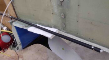
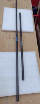
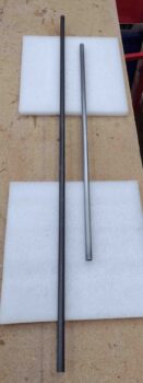
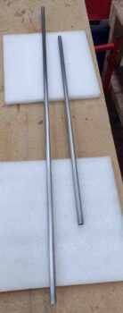
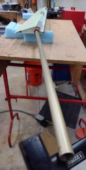
I then rounded up my CS125 and CS126 aileron control tubes that connect the CS128 bell crank to the aileron control tab on the firewall.  There was a tad bit of surface rust on the 4130 steel control tubes after all these years, so I decided to do a bit of corrosion control and prevention.

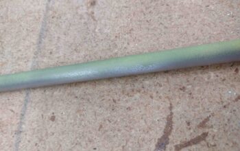
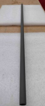
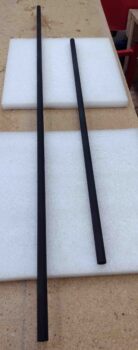
The first pic on the left is the raw aileron control tubes.  In the middle pic the shorter tube has been sanded and cleaned up, whereas in the last pic on the right both control tubes have been sanded, cleaned up and acetone-wiped for painting.

I started to prime the aileron control tubes with Zinc Chromate, but I guess the paint can had gone bad since after a couple of passes it just wouldn’t fire anymore.  I tried with no avail to get it to shoot but no joy,

So I brought the partially primed control tube back into the shop and cleaned off the Zinc Chromate I had shot onto it.

I then grabbed my trusty can of Rustoleum self-etching primer and hit the tubes with that (left pic).  After a good hour-plus cure I then shot the control tubes with flat black exterior automotive paint…. which cures to full hardness in 48 hours.


My last task of the evening was taking the right lower winglet outside and sanding it in prep for further glassing and micro finishing.

Tomorrow will be a light build day since I’m leaving mid-day for Raleigh to attend an overnight Halloween party with Jess.  Upon returning I intend to upgrade my CS spar wing bolt brackets and get the wings installed in prep for shaping and glassing the strake tops.


Chapter 19 – Wings officially complete!

I started out today by whipping up some dry micro using EZ-Poxy and filling in the remaining gaps in the fuel probe wire channels on the tops of the strakes.

I then grabbed my CS132 weldments and marked the center line on each part.

I spent a good little bit of time riveting up one side of the CS129 control tube, for both wings, and then taped the other rod end insert into place since I wanted some wiggle room on determine the final length of the CS129 tubes.

I had to run out and get some errands knocked out, and I returned later in the afternoon.  While it was still light out I sanded the left winglet (about an hour) to prep it for install, subsequent glassing and micro finishing.  Next up on the sanding docket will be the lower winglets.

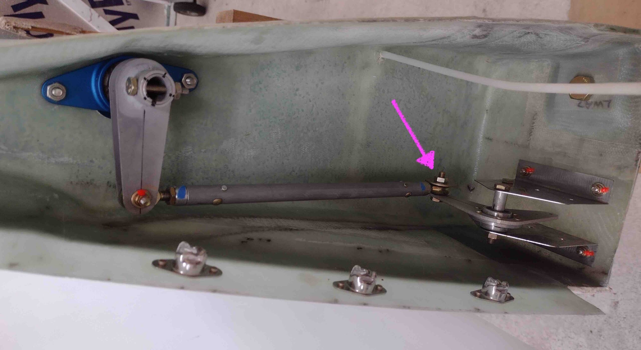
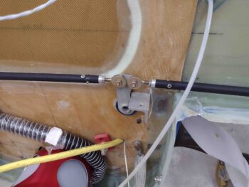
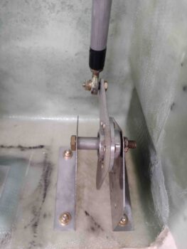
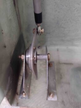
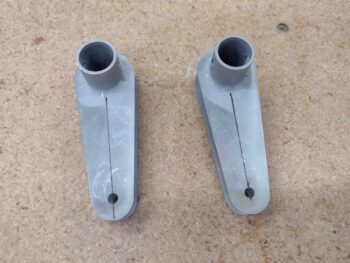
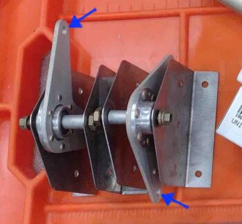
I then got busy installing the wing aileron control system components.  As I was working the initial task of determining the 90° angle between the CS132 weldment and CS129 control tube, I set the CS128 bell crank and brackets in place (bottom of pic).

On the recommendation of Wayne Hicks in his write-up, I had also left my CS129 at 9.3″ vs the plans 9.1″ to ensure I had enough length if required.

Well, I could tell that my CS129 was way longer than it needed to be… something didn’t seam right.  I did a little looking in the plans and realized that the original rod end inserts did NOT have the 0.2″ tall end caps that the new ones do.  So with 0.2″ extra on each end plus my 0.2″ inches for some wiggle room on length, I was sitting at a minimum of 0.6″ too long on the CS129.  Even with the rod ends bottomed out I was too long to have any semblance of getting the required 90° between the CS132 & CS129, or the next 90° between CS129 and the CS128 bell crank.

I trimmed my CS129 control tubes down to 8,5″ each and pressed forward.  Although the rod ends are still threaded in more than what I would think is “normal,” I could at least dial in the required angles with these components in the wing root.

[Note the hash marks on the end of the CS152 tube aligning it to CS132]

Again, although I was focused initially on the 90° angle between CS132 and CS129, I worked the angles as a system to keep the CS129 tube distance off the rib wall consistent and the angle of CS129 with the lower inside wing root surface consistent as well.  And before finalizing the CS132 to CS129 right angle, I also made sure the CS129 to CS128 90° angle was fairly close to final.

I’ll note that keeping these 90° angles on track resulted in pushing my CS128/CS127 bracket assembly more inboard and further down than I saw in plans or other builders’ installs.  I worked it for a good bit to make sure I wasn’t screwing anything up, but given the components I had on hand while maintaining those two 90° angles drove the placement of CS127 brackets to where they are in these pics.

After ascertaining the right wing’s CS132 right angle with the CS129 control tube, I removed the aileron assembly and then subsequently removed the CS151/CS152 combo off the aileron.  I hand drilled the top marked bolt hole into CS152 that would be used to attach CS132 to it.

The hole through CS132 was not straight, and being offset a hair required me to hand drill the holes on each side separately… and when I say “hand drill” I mean without the use of my tube alignment block that I normally tape and clamp to a tube to get a near-perfect straight and centered hole.

Here we have the right wing CS132 bolted to the CS152 tube, thus connecting the CS132/CS129 components to the aileron…  another significant segment added to the linkage (yes, here my clocking marks are off by about 0.015″ and while not perfect, were a good bit closer when the bolt was fully seated and tightened).

I reattached CS151/CS152 to the aileron and then reinstalled it into the right wing.  I then bolted the CS132/CS129 combo to CS152 that enters into the wing root area through the root bearing.

My next task was dialing in the 90° between CS129 and CS128.  While doing this, I slowly started securing the CS127 brackets into place by drilling out the bolt holes and securing the CS127 brackets in place as I kept verifying the 90° angles were good.  I will note that the third bolt that went in knocked my CS132-to-CS129 right angle off a degree or two, but in assessing this setup I just chalked it up as the cost of doing business… I don’t think I’m going to get much closer than that.

Now, I’ve blathered on about focusing on my two plans-required 90° angles inside the wing root… and as any military planner knows all plans may be perfect up until first contact with the enemy.  A primary goal in this setup is to have 20° up-travel on the aileron that is noticeably ensured when the CS128 bell crank hits a hard stop bolt across the CS127 brackets.  I was getting that until I secured my last couple of mounting bolts on the CS127 brackets —even though they were clamped tightly in place while I set the component configurations.

It took me a good 45 minutes of slowly dialing in the rod end in/out threaded length and thus negating my oh-so-conscientious focus of nailing the CS129/CS128 90° angle.

To get my 20° aileron up travel (above… 180-160 = 20) —which equates to a hair over 2″ swing/gap between aileron trailing edge vs wing trailing edge— I had to come off my CS129/CS128 90° angle by an estimated 2-3°.  Again, the cost of doing business IMO.  If anybody out there has any insights or a better technique, please let me know.

I then repeated the whole affair on the left wing.  Being better mentally prepared and knowing how to initially set everything up fairly close to my final configurations not surprisingly made this exercise go much quicker and smoother on the left wing.

After all the aileron control components were installed on the left wing, and with again needing to sacrifice a degree or two off my near perfect CS129/CS128 90° angle, I was seeing almost 21° on my aileron up-travel and 2.1″ gap between aileron and wing trailing edges.

I’ll note that the last half inch up travel on my left aileron is marked with the inside bolt squishing into the interior wing foam… so I still have a bit of house cleaning on the inside of that channel to accomplish.

Early next week I’ll receive, mount and dial-in the MM-4 rod ends at the CS129/CS128 connections, where the black electrical tape is currently and temporarily securing the rod end adapters in the pics below.

It was quite late, but excellent progress on the day.  Although I do have a couple minor tasks to complete, I can finally say that I’ve finished Chapter 19!

As par usual, I headed in for a late dinner and to check over my notes.

Chapter 16/19 – Rigging Aileron Controls

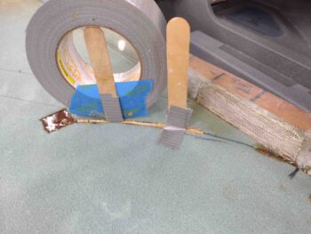
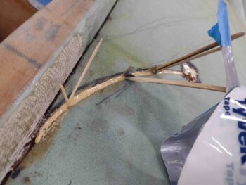
I started out this morning by whipping up some EZ-Poxy dry micro with E-Z 87B hardener and laying it into the fuel probe wire channel on each strake top.  I have taped-up stir sticks and toothpicks in place to secure the wires at the bottom of each channel to keep them as far away from the surface as possible… for when I eventually sand the foam tops of the strakes, pre-glassing.

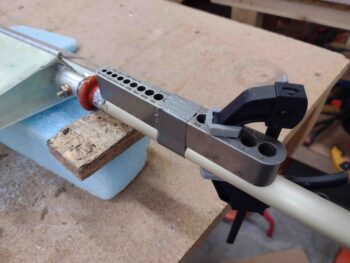
I then got busy drilling out the outboard ends of each CS151 aileron torque tube to allow me to bolt it to the aileron Universal Joint.

I got both CS151 aileron torque tubes drilled and bolted onto the aileron U-joints using the plans called-for AN3-11A bolts… more on those below.

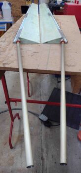
A wide angle shot of the CS151 aileron torque tubes bolted to the ailerons.

I then took a “break,” grabbed my right winglet and sanded it outside in front of my shop. It cleaned up nicely and is now ready for install, subsequent glassing and micro finish.  I plan on sanding the left winglet tomorrow.
I

I’ll first digress for a bit in saying that while I was in the Air Force I was part of a number of multi-month/year long deployments, exercises, etc.  An odd feature that us deployed bubbas recognized was that things were bearable up until the last few weeks of the deployment.  When you know that you’re rotating back stateside in just a mere few weeks, things that you dealt with for a year suddenly became irritating as all get-out. The closeness of normality just out of reach caused all the idiosyncrasies of the current crappy situation to magnify all the crappiness of each little thing.

So just maybe I am getting really close to finishing this bird, because my irritation level for seemingly unwarranted BS is pinging rather high.

Now, I’m not trying to make this ‘Bash Cozy Girrrls’ week or anybody else, but another issue that Ary pointed out on his blog was that the CS152 through-root-bearing-tube      —that attaches the CS132 weldment inside the wing root to the CS151 aileron torque tube inside the inboard wing channel— comes pre-drilled and set inside the CS132.

The issue is that per plans the CS132 must be set at 90° to the CS129 control tube WHILE the aileron is at 0°.  If the aileron/CS151 combo is installed and the aileron secured at 0°, then setting the CS132 weldment at 90° to the CS129 needs to all occur inside the wing root… in other words, the variable being manipulated needs to be the CS132 placement (clocking) onto the CS152 tube.

With the CS152 pre-drilled and attached to the CS132 weldment, this variable is now moved BEHIND (read: out of sight) the wing root bearing at the CS152 attachment point to CS151.  Clearly this infuses a level of complexity that could very easily result in aileron control system components being misaligned… Ary solved this issue by simply using another piece of tubing for the CS152 tubing and eliminated the pre-drilled issue that way.

Having more time to ponder on it, I simply decided to reverse the CS152 tube and pre-mount it to the CS151 aileron torque tube.  This moves the CS132/CS129 90° angle finding exercise back into the wing root and puts the CS152-to-CS151 as a known quantity (aka ‘constant’).

[As a point of note and to be fair, I wasn’t sure if I was missing something so I talked to Chrissi about this exact issue a couple months back… with no real resolution.  We had a long conversation about a multitude of other things and I am truly extremely fond of both her and Randi… but these build issues still need to be dealt with and addressed, IMO].

I measured the width of the wing root bearing, the attach tube portion of CS132, the 1/4″ spacing on each side of the wing root bearing, and the remaining portion of the CS152 tube that would be left to insert into the inboard end of CS151.  I then marked CS151 for drilling.

And prepped CS151 for drilling to mount CS152.

Once I drilled CS151 and bolted CS152 into place, I test-fitted the wing root bearing and CS132 into place to get a visual on if my measurements were correct.  They were… Bingo!

Here we have the CS152 4130 steel tubes bolted into the inboard ends of the CS151 aileron torque tubes using the plans called-out AN3-11A bolts… again, remember these bolts!

Why remember these AN3-11A bolts?!  Because they are TOO friggin’ long!!!! At least for my set up.  When I finished out the wing aileron cut out shear web I naturally overlapped it into the entrance of the channel where the CS151 runs inboard to the wing root rib.  Well, the AN3-11As are so long that on my right aileron it literally locked the CS151 into this channel and in forcibly removing the aileron I inadvertently dinged one edge.

I hadn’t yet put the left aileron/CS151 combo into the left wing yet, so I immediately swapped out the two AN3-11A bolts for the only two AN3-10A bolts I had on hand… and yep, 2 threads showing!

Even then I had clearance issues with my left aileron inside that channel.  Not nearly as bad as the right side.  When I pulled out the right aileron I lopped off that excess crap with my Dremel Tool.

Now, my wing cores are Feather Light, so I am not entirely sure what is going on… since 1-2 plies of BID inside the entrance to that aileron torque tube channel shouldn’t be causing such hate and discontent with these bolts… but it is/was.  And I can’t imagine I’m the first builder to have this issue.

Regardless, I shoved my Dremel Tool cutoff disk down into the opening of the channel and ground away the interior glass to remove what was the glassed wall of the channel —again, just a few inches into the channel— to allow clearance for these damn bolts!

After this round of playing Johnny F— Around in my naivety of following the plans (I’ll note those bolts just looked way too long when I installed them) and correcting even more needless BS, I then installed the aileron/U-joint/CS151/CS152 assembly into each wing, capped off by then mounting the wing root bearing with CS152 exiting into the wing root as it should.

I then set the CS132 weldments in place.  Tomorrow I plan on getting those, the CS129 control tubes and the remaining wing root aileron control tube components mounted.

I’ll further note that I checked the swing of the ailerons and for each wing the minimum I’m getting from aileron trailing edge to wing trailing edge is about 2.25 inches.

And with that, I closed up shop to have dinner and a well-deserved libation.

Chapter 16/19/25 – Aileron control tubes

In preparation for installing the aileron control components in each wing, I am reviewing and assessing how my fellow builders accomplished this task… mainly Dave Berenholtz and Ary Glantz, both very talented builders in their own right.

In reviewing Ary’s excellent write-up on his blog I came across an issue that was hiding in plain sight.  I’ll start by stating emphatically that I love the Cozy Girrrls, Chrissi and Randi, and all they’ve done for this community.  But I have to say in all honesty that I’m disappointed in the info I just unearthed on Ary’s write-up concerning the aileron control system CS128 Belcrank that they sell.  As innocuous as it may seem, their belcrank comes with 1/4″ holes on each arm for attaching the control tube rod-ends.  On the surface no big deal, but it’s definitely causing me headaches in time, money and effort . . . read on.

Without doubt using 1/4″ holes here is in line with the plans changes in CP 102 and CP 103 to increase the size of the rod ends from 3/16″ to 1/4″, at least on the face of it. And maybe using 1/4″ rod ends is a standard in the Cozy world.  However, after this mod hit the streets and Long-EZ builders, fliers, and/or owners were tasked with converting their rod ends, Rick Girard, Ken Miller and others discovered a little gem sold at Wick’s Aircraft: the XM-3.  In Rick’s words:

“First thing is, do not use HM-4’s. Wick’s has a rod end that has a 3/16″ hole in the ball and is in every other way equivalent to the HM-4. This will save having to drill out all the bell cranks. Wick’s part number is XM-3 (I know it doesn’t make sense unless the dash number spec’s the hole in the ball, but it is a 1/4-28 thread).”  Read here, page 22.

I followed suit and bought 8 of the XM-3 rod ends for the aileron control system.

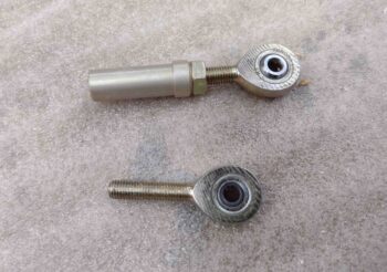
And now I’m following suit after reading Ary’s blog and buying four Heim HM-4 rod ends in a scramble to get the aileron control system installed.  To be fair, the CS128 listed on the CG site does state it uses MM-4 rod ends, but it would have seriously made life way easier for a number of builders if these were produced with 3/16″ holes to then allow HM-4/MM-4 users to simply take a minute to drill them out to 1/4″.

I’ll know and assess more when I get the 1/4″ rod ends in hand, but looking at Ary’s write-up the kicker isn’t really even the requirement or cost to get these new rod ends: it’s the resulting lack of clearance with them installed.  Ary stated that he had to rewicker the configuration of the Belcrank in the CS127 brackets by trimming down the CS131 spacer and adding washers below the Belcrank to reposition it higher simply to add clearance for the bigger AN4 bolt heads.  Now we’re getting into make-work on a supposed off-the-shelf part… which is quite frustrating to a project manager like myself.

I thus fired off an order to Aircraft Spruce for these new rod ends and a few other parts.

Moving on.

I’d say I took my frustration out by sanding the top of the left wing in prep for micro finishing it, but let’s be honest: sanding sucks.  As on the right wing, I spent about 2 hours getting a good dull finish on the top surface of the left wing.  The good news is that I plan to follow Wayne Hick’s lead and peel ply the top strakes when I glass them, which only leaves the winglets as any major area to sand remaining… as far as fiberglass.  Obviously lots of micro-sanding left in my future!

After a bit more research, confirming task sequences, etc. I dove into the initial steps of installing the aileron control system components.  Again, pulling from other builders (a shout out again to both Ary and Dave), my overall plan falls in line with Wayne Hicks specific suggestion to start from the aileron itself and install inward towards the firewall (which is fairly in line with the plans method as well).

I first positioned, drilled and bolted a MS20271 B10 Universal Joint into the A10 tube on each aileron.

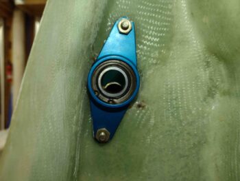
Over on the actual wings I mounted the wing root bearings then slid the CS152 tube with the CS132 weldment bolted to it into each bearing.

I then took the CS151 aileron torque tubes and slid them into place over the CS152 tube and pressed up against the internal face of the wing root bearing.

I then made a mark on each CS151 even with the inboard edge of the wing aileron pocket.

With that, I subtracted the distance of the aileron A10 nub and (now) added U-joint, which is 1.9″.  I also needed to remove another 1/4″ for the space identified in the plans that needs to be between the end of the CS151 tube and the wing root bearing face.  With my measurements calculated and marked, I then trimmed both CS151 aileron torque tubes to length.

And then temporarily mounted the CS151 torque tubes to the inboard nub of the Universal Joint using electrical tape.

I then carefully mounted the ailerons onto the wings with the CS151 torque tubes temporarily attached.

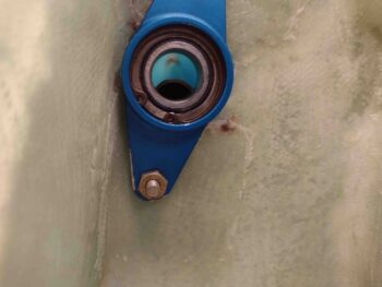
I removed the CS152/CS132 setups out of the wing root bearings to allow me to see the end of the CS151 aileron torque tube inside the bearing center hole.

Here we have a view of the CS151 aileron torque tube inside the hot wired inboard wing channel.

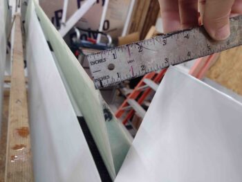
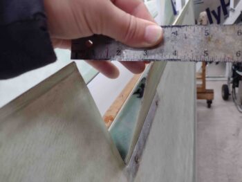
I measured the gap between the inboard edge of the CS151 aileron torque tube and outboard face of the wing root bearing on each wing.  On the right side I’m right about at a 1/4″ gap, while on the left it’s a little shy at 0.214″… so I’ll shave just hair more off the left CS151.

I also noted another issue when remounting the ailerons for the first time after having laid down primer and paint on the bottom surface of the wings: my gaps between the inboard aileron edge and wing aileron notch is essentially AWOL on the forward side of the aileron.

On the right wing you can see it needs some cleaning up to regain the nice gap I had… at this point the aileron is pretty much locked into place as far as any movement.

Over on the left wing I removed the aileron and trimmed the inboard edge to allow freedom of movement, although it started out looking pretty much like the right aileron did above. It was getting quite late so with the left good I decided I’ll fix the right aileron tomorrow.
I will note that I’m happy with the initial aileron swing of 3″ each direction, showing that even with the CS151 torque tube installed that the opening of the inboard aileron pocket is plenty large enough to allow for freedom of movement.  How this plays out once all the components are connected up remains to be seen!

And with a long day under my belt I called it good and headed in for a late dinner.

Chapter 21/22/25 – Strake glass prep

Now the prerequisite tasks are all focused on glassing the strake top skins.  Although that being said, I have some personal preferences in what I’m calling prerequisite tasks and the order in which they are completed.

The bottom line is that the wings need to be mounted in order to finalize the shape of the strakes and the interface between the outboard strakes and the wings.

Thus, I started out the first couple hours this morning getting organized and planning for the next steps in this build.  I want to have Chapter 19 – Wings completely closed out as I start on the final glassing of the strake tops.  While I glass the strake tops I’ll also start the process of attaching the winglets.

To finish out Chapter 19 I need to rig the aileron controls between the aileron and the wing root rib area.  I gathered up all my aileron control components and got them ready for install.

I then took the right wing outside and spent about 2 hours sanding down the top of the wing in prep for finishing.  I plan on doing the left wing top tomorrow.  Then the winglets probably the day after that.
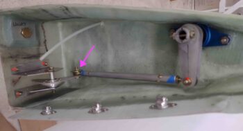
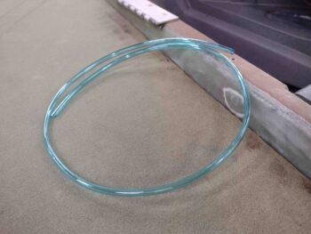
After taking a break from the seemingly endless sanding on the right wing top, I then opened my package from Mountain High Oxygen: 3 foot length of blue oxygen tubing.
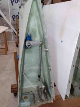
The routing was of course a bit more involved than anything should be, but after about half an hour I finally got the new Mountain High blue oxygen tubing ran from the left to the right strake, via the pilot’s seat back cap… ready to be connected up to the O2 bottle’s regulator and the Y-splitter for the pilot and GIB cannulas.

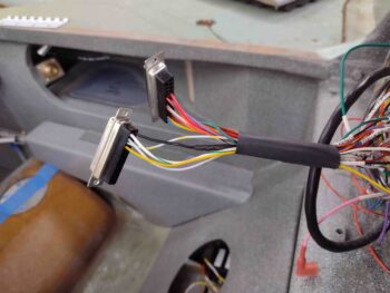
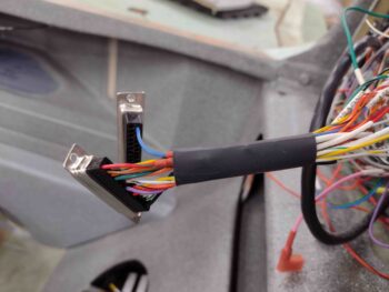
I then spent another half hour swapping out the wires from the old GRT EIS-4000 engine management system D-Sub connector to a new one.

Again, the old one had a socket position that simply wasn’t securing one of the sockets in place.  So far I don’t see any issues with the new 25-socket D-Sub connector.  This task is done and off the list!

Again, tomorrow I plan on sanding the other wing top in prep for both mounting them to prep and shape the top strake skins, but also to add the winglets to and be ready to finish at any time.