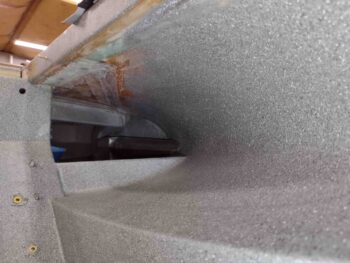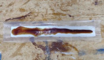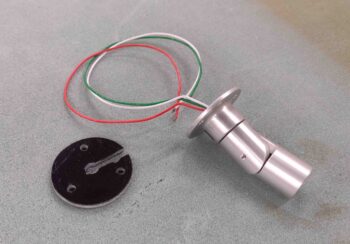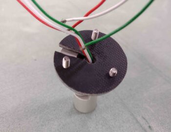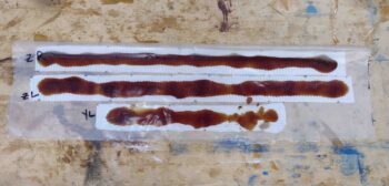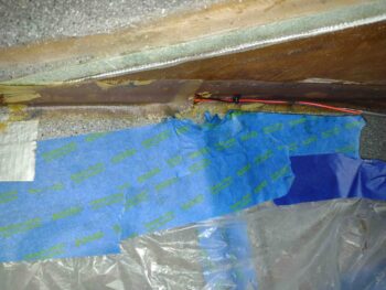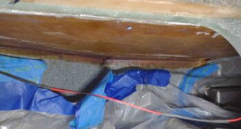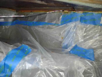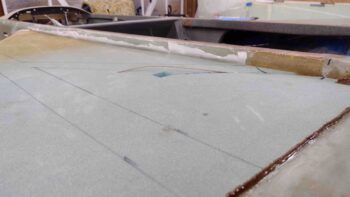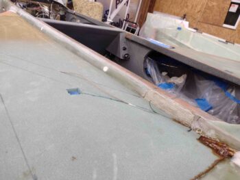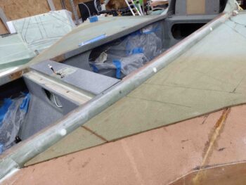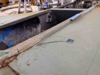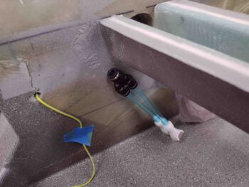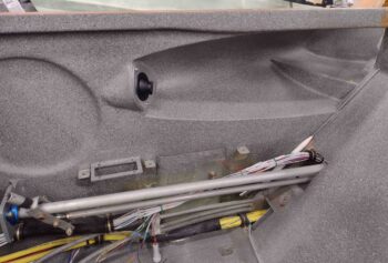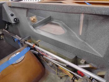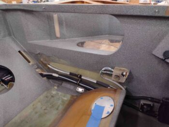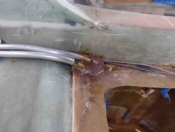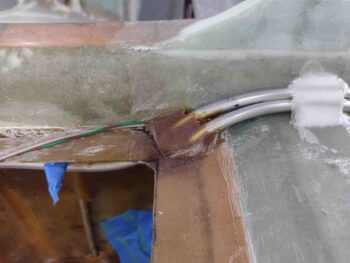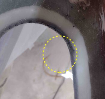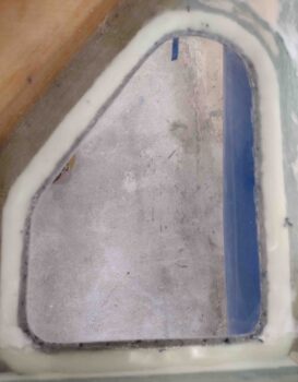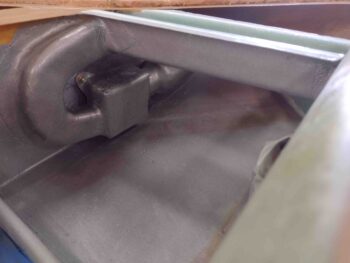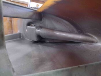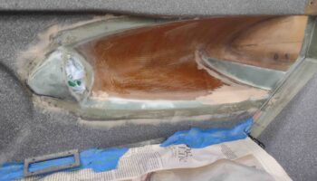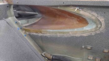
Chapter 21/22 – Fuel Probes Installed

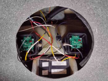
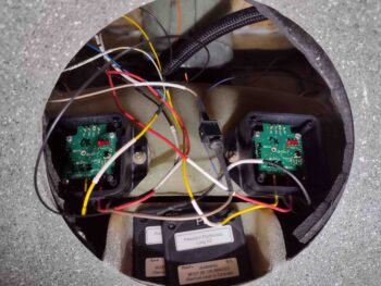
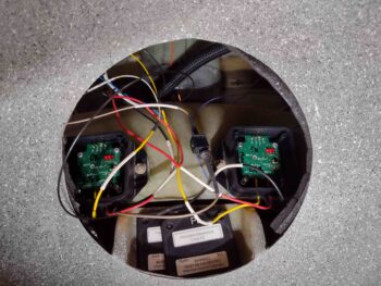
I started off this morning checking the mode my fuel probe electronic control modules are running in… to do so you need to hold down the button and look at the 3-LED bank to ascertain what mode it’s in.  The 3 constantly lit LEDs tell me that these modules are operating in the 5S (set point) mode, which means it will be expecting me to program EMPTY, 1/4, HALF, 3/4 and FULL fuel level set points.

When I queried Nick Ugolini on which mode is best for my Grand Rapids EFIS/Engine Management system, he told me that 2S is the best for GRT.  The 2S mode is looking for basic EMPTY and FULL fuel level set points, and then the other fuel levels can simply be programmed in the GRT EFIS software.
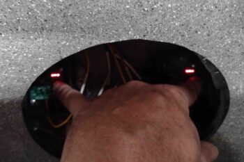
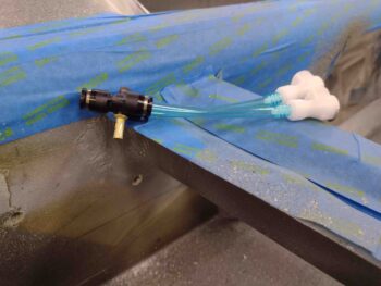
To swap from the default 5S mode to 2S mode, the yellow data wire out of each fuel probe electronics module must be grounded before the sequence to switch the set point mode can begin.  And although my fuel probe electronics modules are just inside the GIB back seat access hole, they are wired up all the way to the GRT EIS-4000 25-pin D-Sub connector residing in the GIB headrest.

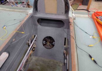
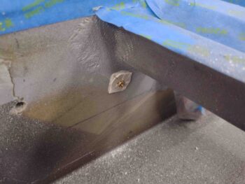
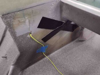
I pulled the cover off the headrest to reveal somewhat of a rat’s nest of wires, but found my 2 wires in a matter of seconds.  As an aside: I actually discovered that my current 25-pin D-Sub connector was unable to hold one of these data wire D-Sub sockets securely in place, and the entire connector will need to be swapped out.
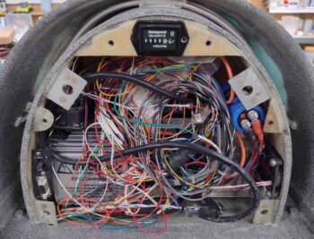
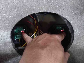
With the data wires grounded, I proceeded to follow the steps to swap the fuel probe electronics module into the 2S mode.  This is denoted by the outboard LED lights constantly on, while the middle one flashes red.  I grabbed a few pics to get one showing the middle LED light “blinking” … step one complete: now in 2S mode!
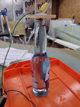
I had gone to the airport earlier today to grab a gallon of 100LL.  The weather today was light rain which was perfect since the airport was very slow and I was able to get right in to get my AVGAS.  I then stopped by my local convenience store to pick up some Corona Lights to use as my requisite fuel container <wink>.

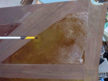
I pre-calibrated my fuel probes one side at a time by starting with just enough fuel in the bottle to have the tip of the probe just barely into the 100LL.  Note that I’m using a wooden disk to secure the probe so as not to have anything conductive touching the probe and potentially throwing off the reading.

The initial EMPTY fuel level set point takes about 16 seconds to process, whereas the FULL fuel level set point is finalized in just a couple of seconds.
With the fuel level set points programmed into the electronics modules, I then got busy physically wiring up the fuel probes.  I had pre-terminated the included ground ring terminals on lengths of wires to connect to the wires exiting out of the CS spar… in my rushing around to get the probes installed, I had mixed up these wire leads on the left and right probes, so just the wires coming off the probes are actually the color of the opposite side.  No big deal, especially since these will get buried in the foam and no one will know except you and me… shhhhh!

I had meant to switch the wires back to the correct side, but didn’t realize the wire color swap again until after I had cut this wire to length to splice and solder it in place.  Oh well… again, it will all get buried and works.

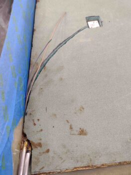
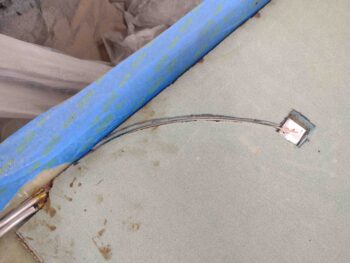
Here’s the left fuel probe ground wire spliced and soldered.
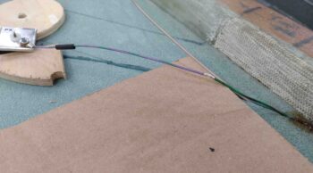
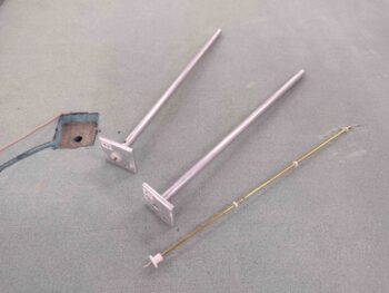
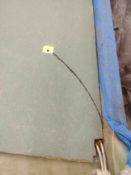
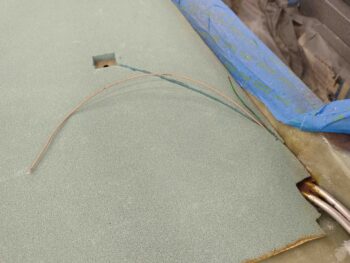
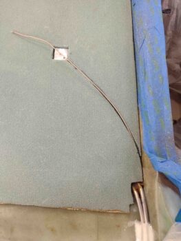
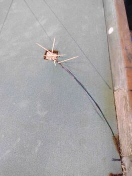
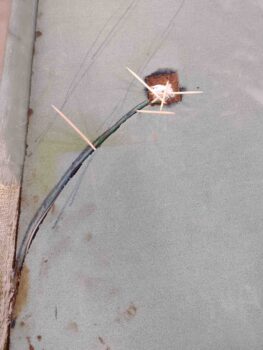
And the left data wire cut to length and soldered to the center sensor probe.  The left fuel probe here is ready to be floxed into the strake skin, as is the the right fuel probe in the second pic below.
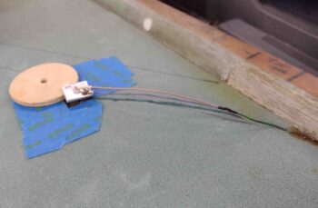
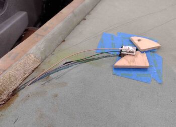
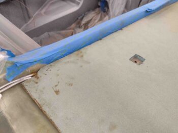
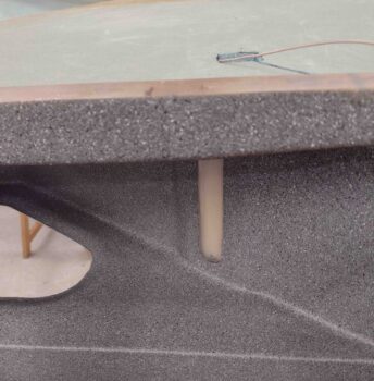
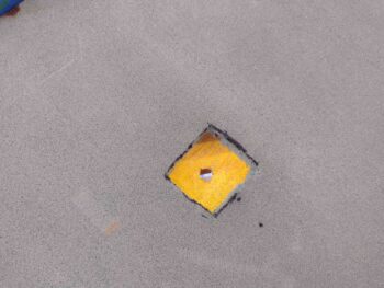
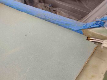
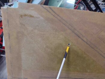
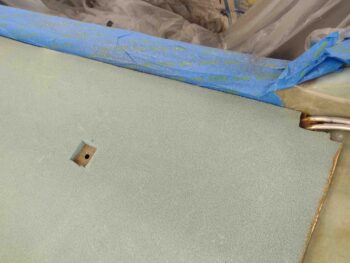
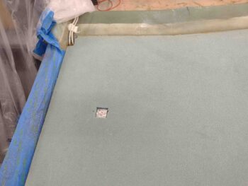
Using somewhat dry flox, I placed it around the perimeter of each notch in the strake top foam… the goals here are to keep the flox from squeezing through the hole and clogging up the vent holes at the inside top of the probe, to seal the edge of the probe base plate to keep the later wet potting flox from seeping into the tank and thus potentially clogging those vent holes, and of course securing the fuel probe in place.

I kept the probes down in their respective notched holes with toothpicks and left them to cure for a few hours.
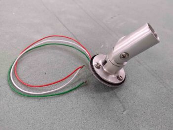
While the fuel probe flox was curing, I fired up the fuel site gage LED lights and turned off all the lights to see what they would look like in near total darkness.  Pretty cool… I love ’em!
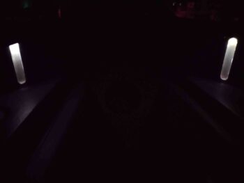
I then wanted to see how they looked in more ambient lighting, so I flipped on a far light. Again, they look great.  I’ll note that in the original install instructions, Vance noted that the LED lights were red… thank God he decided to go with this color! Much better than red! (IMO)
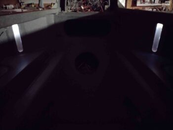
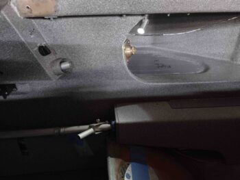
Speaking of red LED lights, I then wired up the GIB map light and fired it up as well.  The default light color I have set when this comes on is red… of course to save night vision.
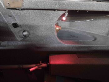
Here’s the GIB map light on its white setting.
Again, nearly 4 hours later I pulled the toothpicks, whipped up some wetter flox (all EZ Poxy on these fuel probes is with 87B hardener) and finalized the potting of the fuel probes in the strake skins.
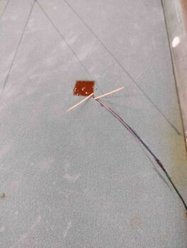
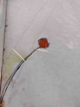
I left a couple toothpicks in place to keep the wires down and secure, and thus the center probe nice and snug against the base of the fuel probe body.

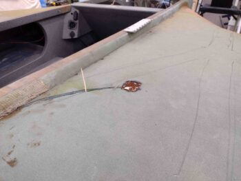
I then left the freshly flox-installed fuel probes to cure overnight.
 

Chapter 21/22 – GIB map light install

Today was a short build day in that pretty much all I got accomplished was the installation of the GIB map light.
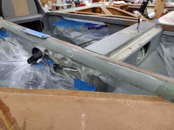
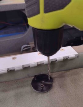
I determined the final location of the GIB map light inside the right strake baggage compartment before drilling the first 2 of 3 holes from the inside.  With the GIB fresh air vent in the way I couldn’t drill the 3rd hole from the inside, so I set up the mounting base on the top of the strake skin and drilled it from the outside.

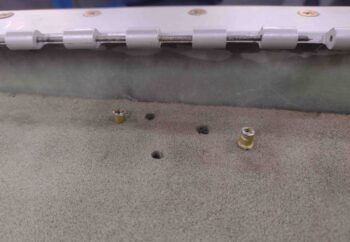
I created 2 threaded nubs to secure 2 of the 3 screws by cutting a #6 RivNut in half. Really these are just to snug up the base to the underside strake skin to allow the securing flox to cure.  Clearly they do add some securing strength, but it just made it easier to flox the darn thing in place by using these (after I sanded the underside strake skin at the mounting site, of course).

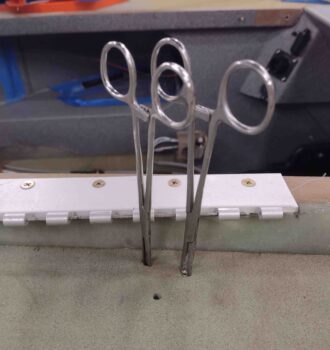
Of course I had to keep these threaded nubs from spinning while I threaded the screws in place, and for that job I used forceps.

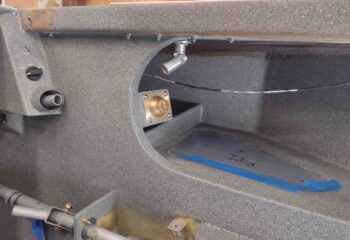
Here we have the GIB map light installed in the right strake baggage area with flox.

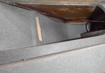
I actually did do just a bit of touch-up painting with the gray granite paint to cover up some of the ugly dark brown/brick red EZ Poxy layups in the upper corners at the aft opening of the baggage compartment.

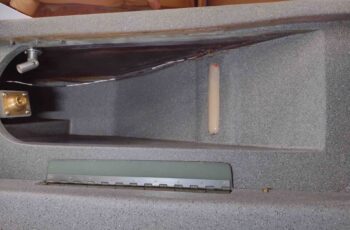
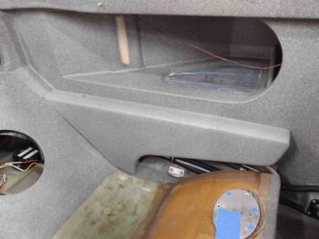
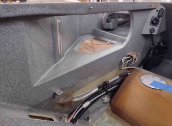
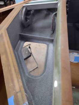
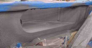
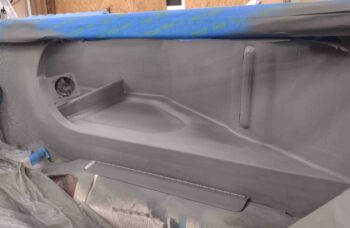
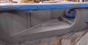
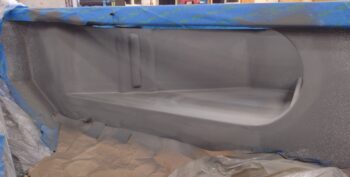
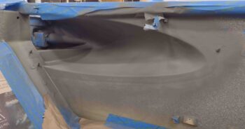
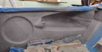
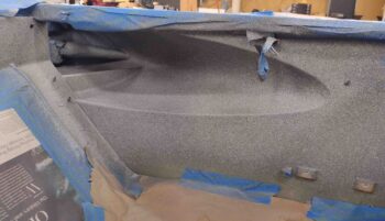
As I mentioned in my last post, here are pics of the internal strake baggage layups.  First, the aft right strake baggage area.

And here’s the aft left side.


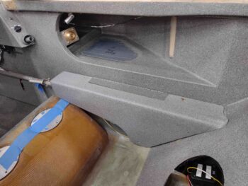
I also temporarily mounted the aft left and right armrests.

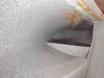
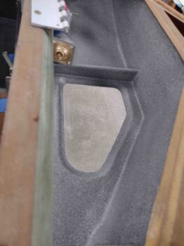
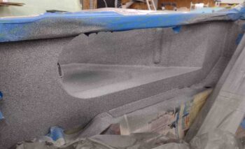
I then grabbed a shot of each side forward baggage opening underside layups.  First the right side.

And then the right side.

With this, I called it an afternoon and headed to New Bern for dinner with my girl.


Chapter 21 – Final internal BID tapes

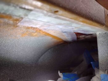
I started out today knocking out the most difficult layup left that faced me to finish out the interior strake BID tapes.  This BID tape is the last in the baggage area that seals the seams between the rib/bulkhead T-hats and the floxed-in-place upper strake skin.

Specifically, this is the right side layup between the top of the BL23 rib T-hat and the underside strake skin.

That being said, I did do a few more layups inside the strakes, although I didn’t get pictures of those.  I guess I really wasn’t in a picture taking mood today but I’ll grab some pics and detail those tomorrow.

I did get the base mount for the GIB map light figured out and constructed.

I simply used a 1-1/2″ hole saw to cut a disk out of 1/8″ thick phenolic.  The reason for this disk is that I need a spacer to allow for a channel for the wires to run through… which I cut in the disk with the Dremel tool.

I then drilled the 3x #6 mounting holes in the base.

Here we have the #6 screws securing the map light to the 1/8″ thick phenolic mounting base.

And another shot of the map light secured to its mounting base.

I had planned on floxing in and installing the GIB map light later this evening, but when I wetted out the prepregged ply of BID for the right longeron-bare fuselage side foam-strake skin layup at the GIB strake baggage opening, I had a brain fart and used half slow and half fast hardener.  This added hours to the cure time so I’ll have to wait until tomorrow to install the GIB map light.
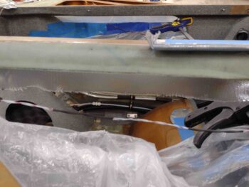
With some epoxy left over in the cup from this layup, I quickly prepregged about a 2″ x 2″ ply of BID and laid it up in the right front corner between the original fuselage sidewall
—just off the front seat face— and the underside of the top strake skin.  I then peel plied that layup.  This finalized all the internal strake BID tapes except the left side longeron-bare fuselage side foam-strake skin layup… which I’ll do after the final exterior top strake skin layups.

Chapter 21 – Inside strake BID tapes

I started out this morning by removing the weights, tape and boards from the tops of the strakes.

From what I can tell so far, all looks good as far as the strakes floxed in place.

I pulled the weights, tape etc. in the mid morning, which put the flox cure time under weight at right about 36 hours.

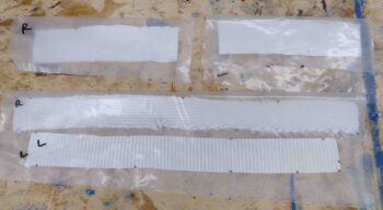
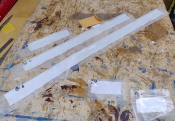
I then cut some BID for the front strake baggage opening, where the there’s an underside bare strip of foam… which is the original fuselage sidewall just outboard of the longeron. This is the top 2 tapes in the pic below, which are about 7″ long.

The bottom BID tapes are the ones I precut before I closed out the strakes.  These are for the inside seams between the installed top skin core and the leading edge flange.

After removing a few flox globs and a good bit of sanding, I then filled some of the irregular spots with flox while I applied wet micro to the bare foam.  I then laid up al the prepregged BID tapes show above.  I then peel plied the BID tapes.

I’ll note that these weren’t the easiest layups, but they weren’t too bad . . .

as compared to this next round…  Whew!

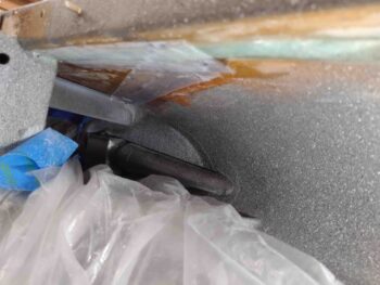
These layups rank up there as some of the most difficult layups I’ve done on this bird. Mainly because I’m laying across the back side of the strake/longeron, hanging my head down inside the strake opening and trying to add a decently long, wet BID tape to a very small corner target.  Admittedly it may have been easier to use aluminum foil here, but probably not much better.

Regardless, I got the 2 aft sides of the interior left strake upper corner seams completed… again, this is a BID tape that overlaps the seam between the T-hat and the underside top strake skin, with a bead of flox along the seam to ensure A) no fuel leakage (thus, EZ Poxy) and B) added physical strength to the strake skin attachment.

I only did the very aft layup on the right side since the front BID tape, above, was still curing and was peel plied.  The left side has a natural gap between front and side BID tapes with the Oil heat RAM air duct/bridge, so there’s not overlap or contact between front and middle BID tape.

Here’s the aft left inside corner along the segment just above the fuel site gage.

This is still some of the aft segment (BAB bulkhead) on the left half of the pic below, along with the segment of the BL23 rib.  Although further in, the BL23 rib was a little easier to layup since it was a shorter segment and also a straight view in… whereas the BAB segment was angled and harder to see and judge distance.

Also remember: EZ Poxy is messy.  It likes to stain everything it touches… so I was trying my best to keep the painted sidewalls clean and unblemished from this rust colored stuff.

On the right side, the focal point in the pic below is all along the top.  This is the EZ Poxy BID tape along the corner intersection of the BAB bulkhead T-hat and the underside strake skin.  I’ll note that I peel plied all these corner BID tape layups.

After I finished the first round of the “layups from hell,” I got busy pulling the peel ply from the 1-ply BID layup that comes off the outboard longeron face and wraps under the long inboard/underside edge of the top strake skin.  Here we have the left side.

Once the peel ply was removed I cleaned up the layup and also sanded the aft 5-inch ply of BID on the longeron.

Here’s another shot of the left side longeron peel ply pulled and aft BID sanded.

I then did the same on the right side… here’s a couple shots of that.

I also pulled out the clamped blocks on the forward side of the aft baggage openings.  I had peel plied the tops of those blocks, so I removed the peel ply from the inside corners as well.

Tomorrow I’ll continue pressing forward with the inside baggage area top strake skins layups.

Chapter 21 – Strakes closed out!

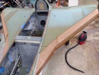
Today was a huge milestone for my Long-EZ build in that I got the top strake skins floxed on and the strakes closed out.

My first task of the day was just annoying, to be honest.  I found yet another epoxy bead from a tape seam as the light hit the left GIB strake window just at the right angle as I was looking through it. Ugh!  I wet sanded it with 600, 1000, 1500 and 2000 grit before buffing it out with my kit.

Done.  It better be the last time (ok, except for the outside… I know that’s coming!)

Not shown here, but I first taped the GIB windows and fuel site gages back up before sanding down the longerons in prep for layups.  I then vacuumed out the dust (both inside the baggage areas and the fuel tanks) before taping in plastic sheeting to protect the just-painted baggage areas from any epoxy or flox gunk that may ensue from closing out the strakes.

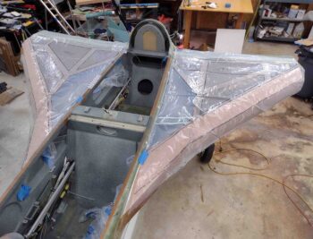
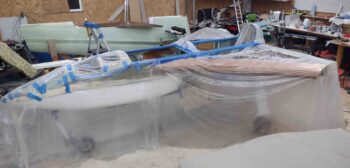
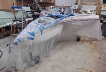
I then took a page out of Dave Berenholtz strake build and covered my open strakes with clear plastic to create a rib/T-hat/LE map for reference later on if I need it.  A 20 minute task that may prove very useful in the future.  Thanks Dave!

I then did a final fitting and prep of the strake top skins.  I also transferred and marked up the T-hat positions actually on the strake skin foam cores themselves.  I wanted to have a quick reference as to where to put the weights once these things were floxed on.

I then removed the strake top skins, vacuumed out the entire fuel tank each side, then removed all the protective tape pieces —fuel vents, drain screens, site gage holes— and then vacuumed again before doing a visual check for any bits of dust or lint.

Unabashedly copying yet another builder, I then took a page from Ary Glantz’s strake build and made up single ply BID tapes that will be laid up on the longerons first, then overlapped onto the inboard underside edge of the strake skins when they’re put into position.  Much easier than the plans method of leaving an inch of glass overhanging down the inboard edge of the strake skin un-wetted-out to then be overlapped upward onto the longeron… as Ary essentially noted on his blog: use gravity as your friend.

I then prepregged these BID tapes.

The smaller ~5″ wide BID tapes in the lower right corner of the pic are the ply of BID that goes from the inboard underside edge of the strake skin and overlaps onto the longeron, only in the very aft where it is sitting on top of the T-hat/flange… so these are separate layups that I used EZ Poxy to layup.  I laid these up on the aft edge of each top strake skin.

I then laid up the forward, longer BID tapes on the longerons using MGS 335 epoxy with a 50/50 mix of fast and slow hardener…. here’s the right longeron with the BID tape in place.

Ahem! I got a little cocky here and should have gone slow hardener all the way because these BID tapes were getting pretty dry by the time I got the actual flox on all the T-hats and strake top skins set in place.  I made it though… just barely.

Here’s the left longeron BID tapes.

I will note that I set the left strake in place first and then moved onto the right side.  At some point I had a bit too much weight in the area above the GIB strake baggage opening. The weight caused this layup to pull back/away a bit as the surface it was attached to moved further down/away.  As I rebalanced the weight on the left strake top a bit later, I wasn’t thinking about that layup.  So once the top skin came back up to its proper position, and with the BID tape well into curing, it simply pulled it upward in its now “elongated” state…. in short, I have a decent bit of bunching right along the longeron bottom/inboard skin seam on the left underside baggage opening.

I clamped the top skin and the longeron to bring the position to the correct height as it fully cured.  I’ll wait to fix this until after I glass the outside tops of the strake so it’s stronger and has support to secure this segment of the top skin edge into place.  Thankfully the right strake is fine.

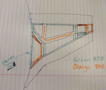
Since I had just a half of a squeeze bottle left of E-Z Poxy 87B hardener left and a bunch more 84B on hand, I prioritized my hardener usage so that I would ensure the actual perimeter of the fuel tank was secured with E-Z 87B hardener (the best stuff according to Gary Hunter) and then the middle/inside rib tops/T-hats got the E-Z 84B hardener.

Here’s my chicken scratch drawing of my plan:

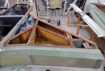
And here it is in application.  Actually the left strake got pretty much exactly what you see above, while I was able to use the 87B on a few more areas on the right strake since I knew I was in the clear.

Although I do have probably just enough 87B for the initial floxing in of the fuel probes.

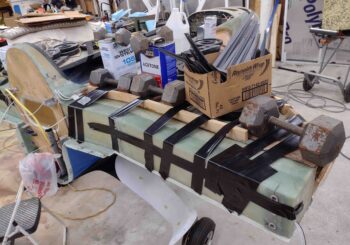
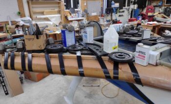
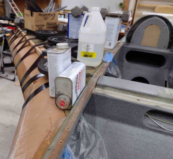
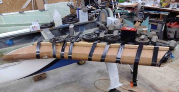
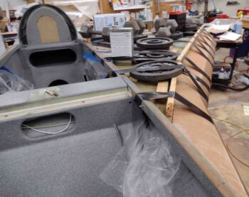
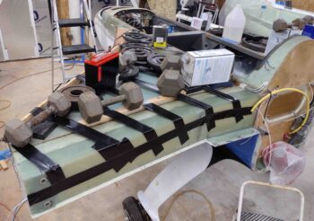
I would call the above the “before pic” while this one below is the “after pic”… with the right strake top skin floxed in place and tons of gym weights and other items weighing it down in place . . .

as well as ACS shipping dunnage wood strips taped in place to really get a good compression on the front edge of the foam where it overlaps the leading edge flange.

Here is the front side of the right strake closeout.

The left strake was actually the first side I closed out.  Here’s a shot of that.

You can see I used a lot more standard gym weights on the left side, which is why I had to get more creative on the right side and use other heavy items to weigh it down.

Finally, here’s a shot of the aft side of the left strake top skin closeout.

It was quite late and a VERY long day… time to have a glass of red and celebrate this milestone before jumping back into the fray!

Chapter 21/22 – Fuel Probe Initializing

The goal today was to get the fuel probes tested out as per the instructions provided by Nick Ugolini.

I wired up the fuel probes . . .

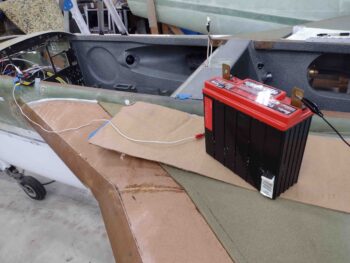
and connected them to battery power.

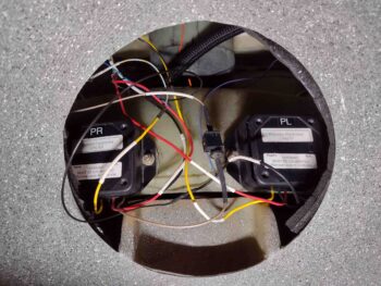
Here are the fuel probe control heads, just inside the GIB back seat access hole.

I then removed the covers to start the initialization test.  The key components on the board involved with any testing is 3 LED lights and a push button.

To start the initialization, you push the button in while applying power to the control heads. Luckily, I was able to push both buttons while powering up the fuel probe control heads.

The first indicator that all is going well is the left red LED blinks… I didn’t want to spend time making a video, so I grabbed a few shots to show the left red LED “blinking” (aka on).

I then kicked off the initialization process, which then goes to the next step with the left and center LED light blinking… clearly the system is working correctly.  After this step I simply pulled the power and called it good.

I’ll note that in corroborating with Nick Ugolini on these fuel probes, he provided an extra information sheet showing how to set up the probes before they get installed into the tanks.

I then spent a good little bit of time wiring up the GIB map light and also the fuel site gages’ LED lights.

This pretty much finishes off all the prerequisite tasks need to close out the strake tops.  In an overview of all my prerequisite tasks prior to closing out the strake tops, I shot this video:

Of course I have a bunch of prep work to knock out before I close out the strakes, but I am going to work my tail off to get this done ASAP.

Chapter 21 – Strake compartments

Today was all about getting the outboard strake storage compartment hinges into place.

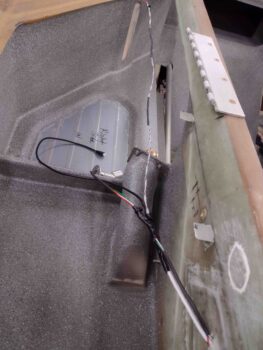
Yes, this is just another mod of many.  I know mods move the timeline to the right a fair amount, but I can’t pass up an opportunity to add some fairly significant and handy storage that will prove —IMO— to be very beneficial and make life easier in the long run.

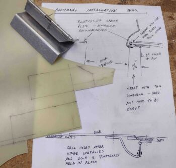
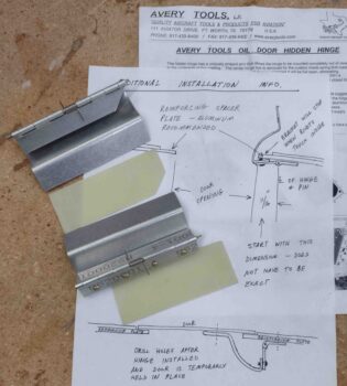
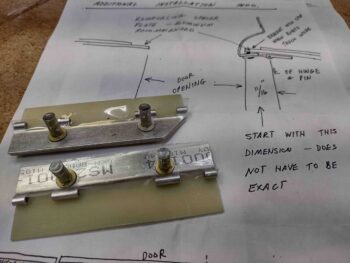
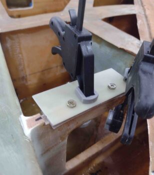
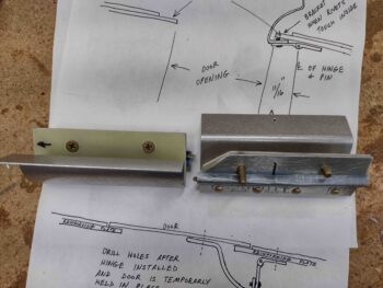
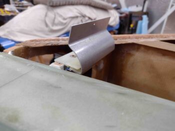
I started out by grabbing my 1/16″ thick stock of G10 phenolic to create a reinforcement plate for each side, as called out for in the included instructions to these hidden hinges.

I took the G10 out in front of my shop and cut it with my saber saw.  I then cleaned them up on the sanding boards and 100 grit sandpaper.

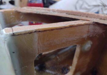
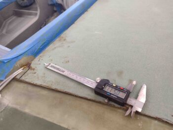
I measured the thickness of the hinge and the reinforcement plate together which came out right around 0.113″.  I set my calipers at 0.105 inches and marked a line for cutout on each “OD” rib.  I then notched the “OD” rib on each side (see below) and dialed in the depth with a bit of judicious sanding.

I then prepped 2x #10 RivNuts for each hinge.  I taped the bottom of the hinge to protect against any gunk and then mounted the prepped RivNuts.

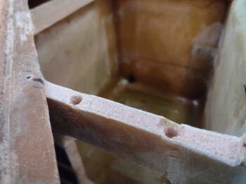
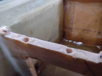
I then prepped the holes in each “OD” rib to ensure the RivNuts could be mounted even with the top of the rib if required.

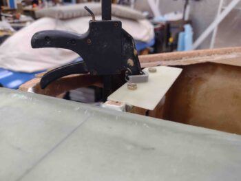
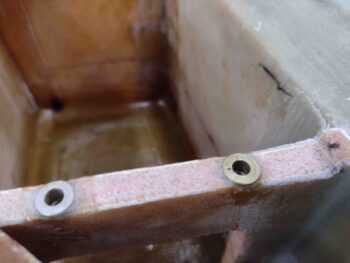
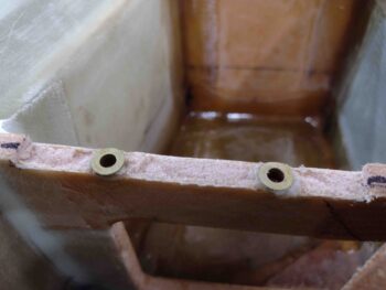
I then floxed the RivNuts into the rib holes and set a clamp on the plate/hinge.  Here’s the left side . . .

And the right.
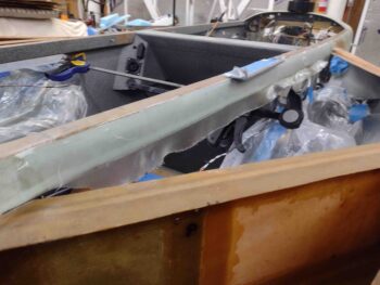
A few hours later I pulled the clamps off the hinge/plate assemblies.

And then took the screws out to reveal floxed-in-place RivNuts in the “OD” ribs.

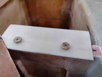
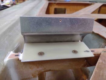
After counter-sinking the reinforcing plates, I then assembled the reinforcement plate/hinge assemblies with countersunk screws in place..

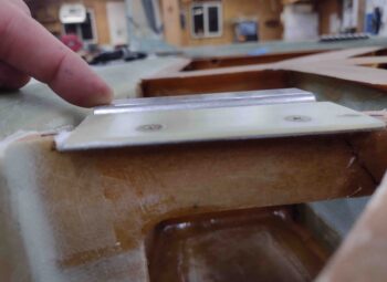
I then used a good bit of flox and micro to install the reinforcing plate/hinge assemblies in place.  Again, here’s the left side . . .

And the right side.

As a point of note, here’s what the right side hidden hinge assembly looks like in the down position.

I set a clamp on each hinge assembly just to make sure nothing crazy happened overnight, and then called it a night myself.

Chapter 21 – Strake/baggage paint done

I started out this morning clear-coating the gray granite paint and quickly noticed that in a few areas the previously near-perfect looking paint surface started mottling up.  At first I noticed it in the area under the right fuel site gage (first pic).

Then, when I looked around at the rest of the paint, I found another mottled area in front of the right front baggage dam.  I’m thinking it was areas of thicker paint that may not have been fully cured (although I let the paint cure overnight) and thus reacted to the clear coat. I’ll note that both the paint and the clear coat are Rustoleum.
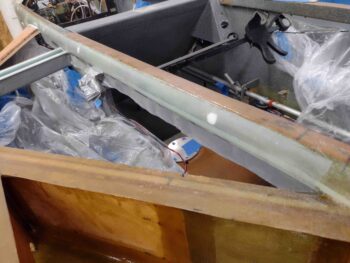
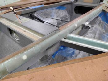
I figured the best way to deal with the mottled paint was to “seal” it in clear coat, let the mottle reaction play out, then wait until the clear coat thoroughly cured before hitting the blotched areas with another shot of the gray granite paint… which then required another 5 hour cure cycle before final clear coat.
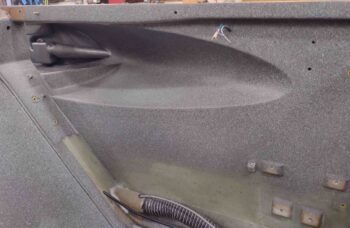
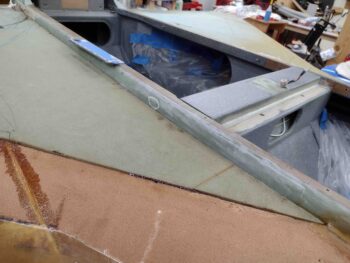
While the latest fresh coat of paint cured, I started working on notching the aft inboard right strake top core to allow it to fit around the exiting fuel vent lines.
I marked up the strake top core as best possible.

Then after a few iterations I got the notch cut and the right strake top fitted.

I then measured and marked the position for the fuel tank probe and after drilling it with a small diameter bit from the exterior side, I then drilled it out from the inside out.

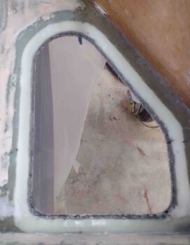
I then marked and cut out a notch for the top flange of the fuel probe.  My measurements for the fuel probe positioning is 5.5″ out from the longeron and 16.5″ from the aft edge of the CS spar forward.

This puts the fuel probe no more than 2-3″ from the fuel site gage, so I should be getting fairly close matching fuel levels on both of those (if I don’t screw anything up!).

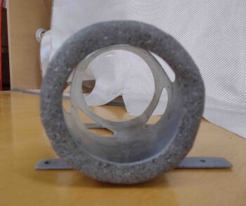
I had planned on floxing in the fuel probe body first (there’s 2 parts: the outer body/sleeve, and the inner probe), before I mount the strake top skin and then merely slide the inner electrically-connected probe into place after the strakes were closed out.

This would allow me to get the probe installed and ensure no flox got into the vent holes near top of the tube. However, the length of wire I have and then running it essentially from Point A (aft strake corner) to Point B (fuel probe) through a channel would require the wires to be long enough to not have the inner probe cant at an angle that could bend the small inner probe tube.  However, since my wires are hard set from the corner forward, if they are long enough to allow me to easily slide in the inner probe, then I would have excess wire on hand and no where to put it… a chicken vs. egg conundrum.

[Note: I thought about a long curved channel to give me more wire, in theory.  But it doesn’t really matter since I have just enough wire on the right side coming from the control box, and just a hair more on the left… so this discussion is merely explanatory)

Thus, I decided to simply —and carefully— flox in the probes after the skins are in place.

I threw a light inside the fuel tank and reset the top strake skin in place… note in the upper corner the edge of the T-hat can be seen.

I then notched the left strake top skin core in the aft inboard corner for the fuel vents, and also measured and marked out the position of the left fuel probe.

As I did on the right strake top skin, I drilled the fuel probe access hole from the inside out for a cleaner hole.

I then marked and notched the left strake top foam to allow inserting the fuel probe flange.

Here we have a shot from the front of the strake looking aft of the left fuel probe being test fitted into the notched strake top.

I then marked and cut a channel for the fuel probe wires (data + ground) on the right side.

I then test ran the wires… looking good.

Here I again have a light inside the left fuel tank to backlight the fuel probe notch.  I’ll note that the right side fuel probe was about as close as I wanted to comfortably get to the T-hat, so I used 5.5″ x 16″ on the left side.  Moving the probe about 5/8″ farther from the T-hat than on the right side.

As I also did on the right, I assessed the wire path and marked the wire channel run.

I then cut the channel for the left fuel probe wires.

And test ran those wires.  Again, so far so good.

I then focused on installing yet another tidbit while I still have unfettered access into the strake baggage areas: a small #6 RivNut hardpoint that will allow me to secure the O2 system’s oxygen tube Y-splitter.  This splitter allows for one feed tube off the regulator on the Obottle in the right strake to then run through about a 30″ line to the left strake where it splits to feed both pilot and GIB cannulas.

[Side note: I called Mountain High to order a longer feed tube to facilitate my configuration above and they simply sent me a 36″ length of tubing free of charge… great customer service!]


I had planned on using a #6 nutplate/phenolic assembly mounted on a 3/8″ thick base of foam, not realizing I had any #6 RivNuts on hand.  Moreover, I can’t find my bag of small rivets and in looking for it found the RivNuts… one problem solved, but I’ll of course need to find my bag of rivets (which I know I have since I used them on the GIB eyeball vent mounting flange!).

Here I have the Y-splitter test-mounted to the #6 RivNut.

I then floxed in the #6 RivNut . . .

and secured it in place to cure with Gorilla duct tape.

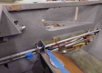
I also ran a yellow pull string to allow for pulling the O2 feed tubing from the right baggage compartment to the left.

A few hours later I pulled off the tape and tape-covered-washer and then test-mounted the Y-splitter… works a treat!

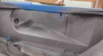
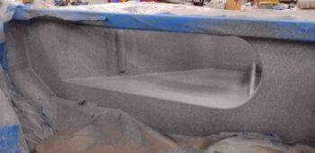
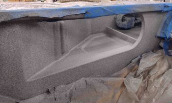
With my clear coat well into the cured state, I then spent a good hour removing all the plastic sheeting and tape to reveal the new FINISHED cockpit and strake baggage compartment paint job.  With the mottled paint issue remedied, I have to say I’m very pleased with the outcome.

Here we have the front right side.

And another angle… with the pilot eyeball vent reinstalled.

Then the left side front… note the slightly different metallic color of the RAM air scoop setup.

And here we have the right backseat area.  As you can see I removed the tape from both the GIB windows and the fuel site gage bubbles.

And the left side GIB area.

Finally, the baggage compartments with the GIB windows.

It was a fairly long build day and now very late in the evening (ahem, morning)… time to knock off for a few hours!

Chapter 21 – Baggage areas painted

I started off this morning by removing the clamps and the spacers to reveal my flox and glass gatekeeper to keep the fuel vents wrangled in the Turtledeck.  While the glass and flox certainly did the job, it’s interesting to note that the pressure I put on the layup squeezed a good bit of epoxy out of the glass layup and made it fairly dry.

I also grabbed shots of the E-Z Poxy floxed fuel vent lines exiting the aft corners of the fuel tanks via the flange.  I peel plied them since there will be more added to these flox bits when the strake tops get floxed into place.

I then gathered up some 600, 1200 and 1500 grit sandpaper and wet sanded the scratch on the aft end of the left GIB strake window.  If you focus on the electrical cord on the ground you can see how it disappears into a haze… that haze is the wet-sanded scratch.

I then buffed out both the right and the left GIB strake windows… and with the windows pretty much scratch free on the inside, it was time to tape them up for paint.

I also taped up a whole bunch of other things as well in prep for paint.

And covered a bunch of areas with plastic to ensure anything that was not supposed to get paint, didn’t.

I then broke out the primer and hit the pilot right baggage opening.

As well as the GIB right baggage opening…

then the left side in the back.

And finally, the left pilot baggage opening.  I have to say, I really like this gray… too bad it doesn’t cover as well as the gray granite paint.

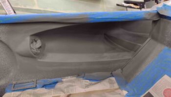
After a good 30 minutes plus, I then painted the inside of the baggage areas and fuselage with the Rustoleum gray granite paint.

I was a bit concerned with how well it would blend with the previous paint, but thankfully it looked like it came out of the same can!  As I always say: better to be lucky than good. Ha!

And the last couple of shots.  All these pics were taken after I shot the second and final coat of paint.

I’m extremely pleased with how the paint looks.  Moreover, I’m glad I took the time to micro up the various spots of the baggage areas to smooth out the rough stuff.

Tomorrow I’ll shoot a couple rounds of clear coat before moving on to the outboard strake storage compartments and preinstall on the fuel probes.

Chapter 21 – Baggage area paint prep

Today I got up fairly early and hit the aft edge of O2 bottle mounting sleeve with a couple rounds of matte clear coat.  I know this picture isn’t that great for the paint, but the structure in the background is a pretty good shot… so I left it in the lineup.

I wanted satin clear for the oil heat RAM scoop components, so I departed for Lowe’s and got there just shortly after they opened.  I then returned and hit the RAM air scoop, vapor box and ducts with 2-3 shots of satin clear coat.

I then got to work on the inside fuselage and baggage areas for final sanding and hole filling, etc. in prep for final paint.  In my mind there is a bit of a priority in how nice you make these areas in order of visibility eh? <wink>  With the front right pilot baggage area getting the most love since it’s the most visible when the plane is opened up.  #2 would be the back seat right baggage area.  #3 would be the front seat left side, with the back seat left side being #4.

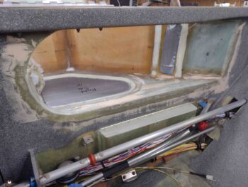
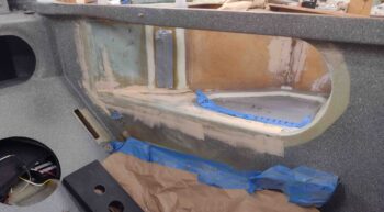
Here we have the front seat pilot strake/baggage openings.  I sanded a good bit inside, as well as the new baggage dams, and quite a bit around the perimeter where the glass overlaps into the main cabin onto the fuselage sidewalls.  As you can see, after some rigorous sanding I then hit these areas with a bit of micro/West 410 mix.

I then moved aft to the back right side.  Again, the main culprit is the overlapping glass into the cabin on the sidewalls.  After a fair bit more sanding I employed micro/West 410 again to help smooth things out.

As I did on the back left side.  I have to say, this was quite the workout leaning into the cockpit and sanding all this stuff.

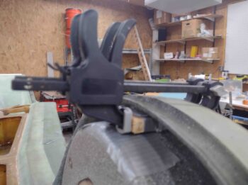
I also whipped up some flox and a couple of plies of prepregged BID, about 3/4″ x 1″, and first floxed up the fuel vent tubes in the center top area of Turtledeck.  I then used a taped up rectangular foam wedge (with the 2-plies of BID and a top layer of peel ply) followed by a taped up 1/2″ thick wood piece to force the fuel vents as far aft into the groove between the GIB headrest and the outer Turtledeck frame.

Hopefully this will keep those fuel vent lines wrangled inside of there until I can figure out exactly what I want to do with all that.

I then whipped up some flox using E-Z Poxy 84B hardener for the right side aft internal corner for the fuel vents exiting out of the top fuel tank flange (again, sorry, no pic).

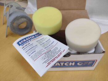
I then pulled down the Scratch Off plexiglass cleaner and scratch removal kit.  I cleaned up the pads in the house since I haven’t used this in a couple of years.

I then got ready to hit the left GIB strake window since I have some pretty decent scratches/epoxy residue from the epoxy wicking up under the tape seams (big sigh).

These are before shots of the scratches…

As is this.

There’s a chart in the Scratch Off instructions on where you should start depending on the type of scratch you have, with it noting that you can always start over with more extreme measures if need be.

Well, I was 3 pads into the sequence when I really noticed one of the big scratches I was going for wasn’t buffing out.  I had skipped Step 1 which starts with 600 grit wet sanding, and went straight to the pads…

Well, tomorrow I’ll go back to it starting with the 600 grit wet sanding.

I will note there is definitely a very noticeable improvement in the overall clearness and cleanliness of the window.  I’ll hit the outsides of these windows at a later point.

After a VERY long day in the shop, I’m calling it a night.