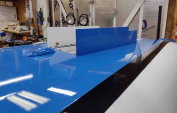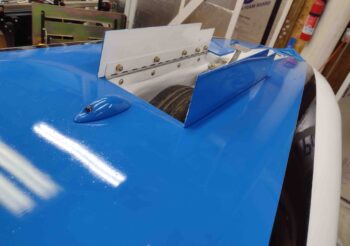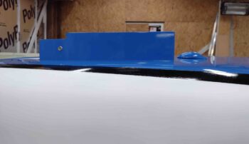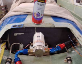
Chapter 21/24 – Strake Top Prereqs

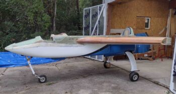
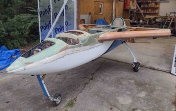
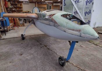
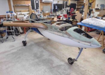
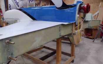
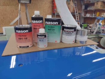
With the plane flipped upright I now need to knock out a laundry list of prerequisite tasks that need to be completed before closing out the strakes.

This pre-strake closeout list includes:
Outboard storage compartments on the top strake side initial tasks
O2 bottle mounting in composite sleeve
Installing main fuel tanks drain screens
Wiring and install prep main fuel tanks fuel probes
Installing/terminating main fuel tanks vent lines
Cleaning up fuel site gages edges (cosmetic)
Wiring fuel site gages LED lights
Installing/glassing GIB strake/baggage compartment windows
Installing/glassing right strake GIB NACA vent duct and eyeball vent
Installing/glassing GIB strake/baggage compartment cross support mini-bulkheads
Installing/glassing/wiring GIB map light
Designing/constructing/installing left/right fuel site gages video camera mounts
Wiring/installing fuel site gages video cameras
Constructing/glassing/installing left strake RAM air scoop/ducts for oil heat system
Prepping/priming/painting strake baggage and final cockpit areas

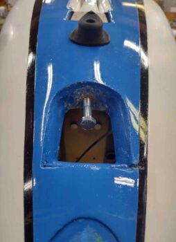
I started off with a good 15 minute look and assessment of the hinge configuration for the outboard strake storage compartments.  I noted my initial plan and gave this mod the mental go-ahead.

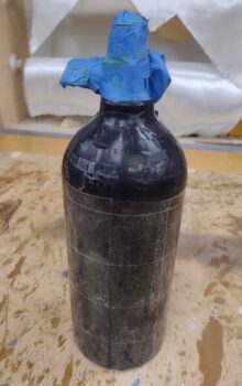
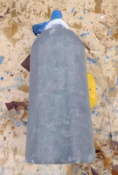
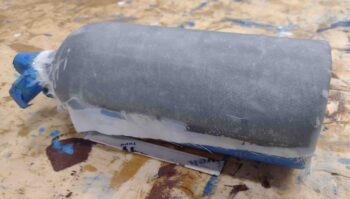
I then got to work on the Oxygen bottle composite mounting sleeve.  I trimmed one side to nearly perfectly half of the bottle, then marked a Sharpie line on the underlying tape.  I then set the other side (below) onto the bottle and marked the midpoint line that I could see through the fiberglass.
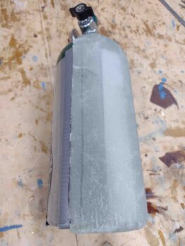
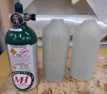
I then trimmed down the second side using my trusty Fein saw.  Here we have the initial fit of the two halves that will make up the O2 bottle fiberglass mounting sleeve.
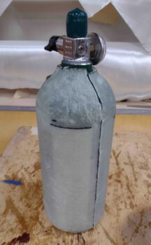
A few more rounds of judicious final trimming and I was ready to glass the two sides together.
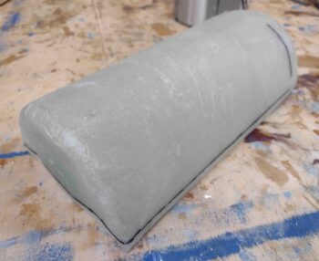
Which I did here, using a 2-ply BID tape on each side.  I then peel plied the layups.  I used MGS 335 here with fast hardener, so I could see the results and remove the bottle from the sleeve ASAP.
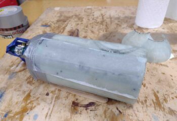
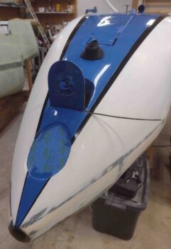
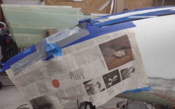
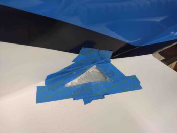
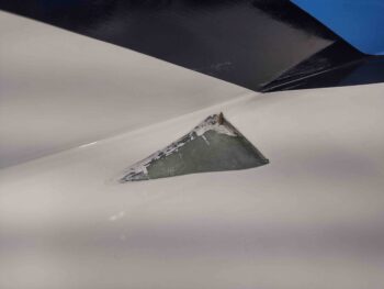
While the combined/glassed composite sleeve cured, I got to work on the right strake GIB window.  Here’s a “before” shot of how it looked from my initial cut from the exterior side.
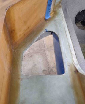
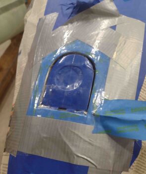
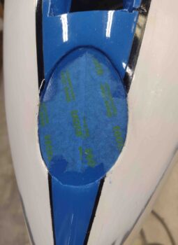
I then taped my template into place and marked the exterior perimeter edge for the inside-baggage compartment cut line.
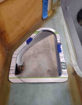
As you can see here.
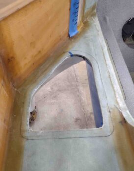
I also marked the cut lines for the GIB NACA scoop.  These 2 separate lines are not mistakes: the inside curved line is for the flat area on the inside of the exterior skin.  The aft cut line is for the angle from top skin to bottom skin, which I’ll carve into the foam and smooth out with micro.
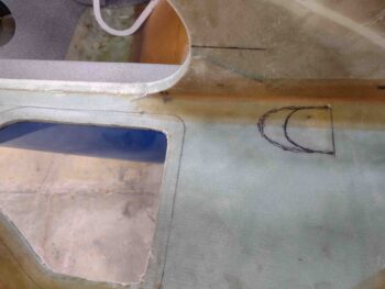
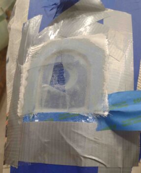
Using the trusty Fein saw again, I carefully cut just the inside skin along the marked line to allow me to remove the glass and foam to emplace the plexiglass (acrylic) window piece.
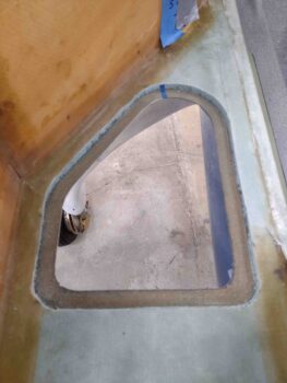
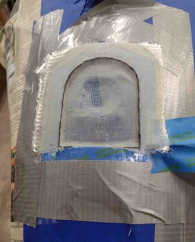
Which I did here, as a test fit.
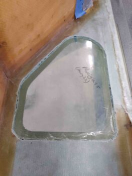
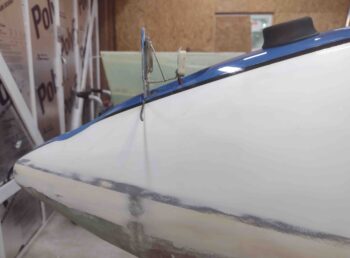
Here’s what the GIB strake window looks like from the outside… I have to say I’m very pleased so far with the results!
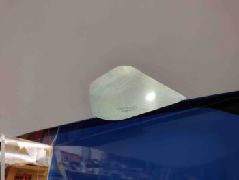
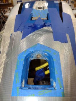
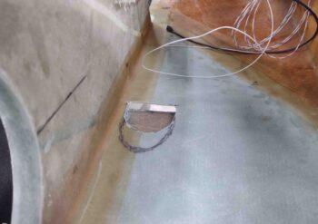
Here we have the NACA scoop initial cut line complete, with the foam and interior glass removed.  Note how you can see through the NACA scoop opening.
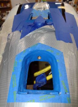
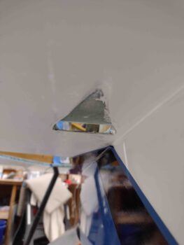
And a shot of the NACA scoop from the exterior side as well.
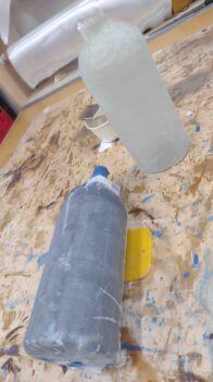
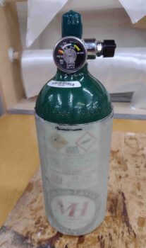
By this point my O2 bottle composite mounting sleeve layups had cured. As per usual, it was a bit of pain and struggle to get the bottle out, but I won the battle.  Here we have the bottle inside its mounting sleeve, with a nice tolerance fit.
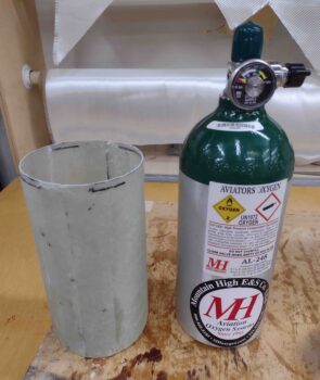
Here we have the O2 bottle composite mounting sleeve, ready to have G10 mounting tabs glassed onto the exterior and some lightening holes drilled into the sides and aft end. Once I mount the sleeve into the right strake baggage compartment, I’ll assess/test different options for securing the bottle into the sleeve.  Right now I’m thinking criss-crossed velcro straps that will keep it in place.
I’ll be attending the Reno air races with friends and visiting family in California for the next 10 days, before I get back for a few days before then taking off again for Rough River.  I’ll squeeze as much work as I can in those few days I’m back, but rest assure that when I return from RR I’ll be pulling out all the stops to get this bird completed ASAP!
Chapter 21/25 – Bird flipped upright

Well, today was the day.  I finalized some wet sanding on the bottom of the strakes and also applied some fine line tape along the black paint edge with the white paint. Clearly way easier to do this last task while the bird is still inverted.

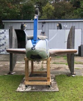
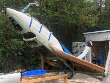
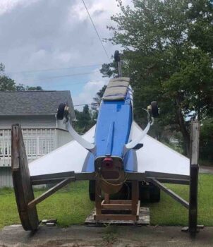
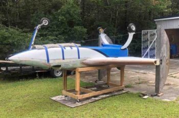
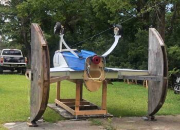
I then went into Star Wars “TIE Fighter” mode by installing the half moon flip brackets.

I also hooked up the winch components and got it online before attaching the cable to the front of the nose.

Since i didn’t want any rubbing of the winch cable on the nose/belly of the bird, I taped padding to the bottom of the nose/fuselage.

In addition, I wanted the nose gear down so I didn’t have to mess with the wiring or the battery, but it presented a slight problem since the winch cable would press/slide up against the nose gear strut fairing.

I used a few plies of blue painters tape and some duct tape to ensure that the winch cable didn’t extract any paint from the side of the nose gear strut fairing.

I manually lifted the nose a significant way off the ground, as I did the first time, to ensure no untoward rubbing or scraping occurred between the fuselage and the fuselage dolly, and to get the winch cable off the belly/nose and further up along the nose gear strut fairing.

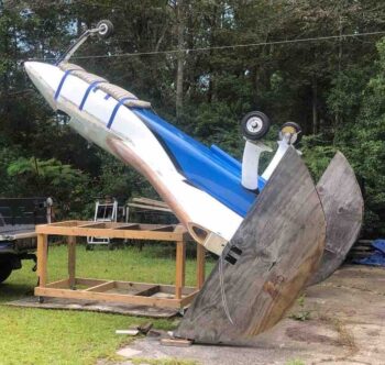
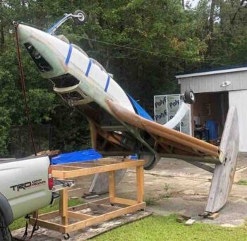
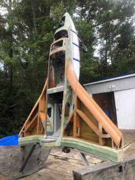
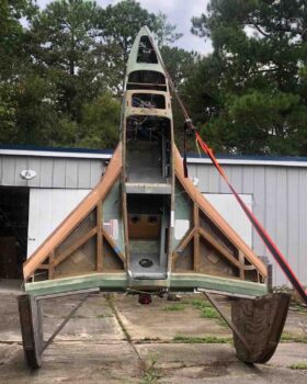
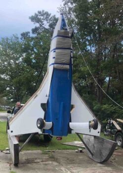
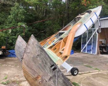
After a bit of time, Jess (my helper) and I got the bird into the now infamous shuttle lunch position.

Here’s a couple more shots of the bird in the shuttle launch position.

We then used tie down straps attached to the nose to very slowly lower the nose down onto the nose wheel strut.  The other end of these tie down straps were attached to my truck trailer hitch and we simply backed the truck up very slowly to ease the nose down.

And Voila!  The bird has been flipped and ready to press on.
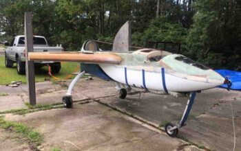
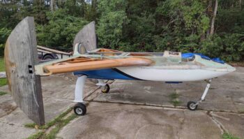
A side shot of the just flipped bird with the half moons still attached.

Here we are a bit later after the half moon flip brackets were removed and the bird is about to get moved into the shop.

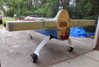
A couple more side shots of the just-flipped fuselage/nose/strakes.

And one from the other side, for posterity’s sake.

And finally, the bird is where it belongs (right now) in the shop, ready to be finished.

Once back inside the shop, i gave the upper side of the bird a fairly good cleaning with Simple Green. I also removed the longer “wing” bolts from the CS spar.

Here’s a video that recounts our bird-flipping adventures!

With a good day’s work under our belt, we were ready to call it an evening!


Chapter 25 – Closer to flipping

Before I flip this bird back upright I need to make a lightweight faceplate to attach to the front of the taxi light to cover the gap between it and its pocket in the nose.  Besides the aesthetics of how the taxi light sits in this nose pocket, I’m also concerned about air leaking around it and both causing the fuselage to be drafty, and causing drag.

Here’s a side view of the current taxi light front face.

I taped up the current taxi light face separately than the surrounding nose, since I wanted to capture the current gap with the 2-ply BID layup.

Which I did here.  I then peel plied the layup.

Another shot of the soon-to-be new taxi light front face 2-ply BID layup.

I then marked the outline with a Sharpie of the current taxi light opening in the nose.

A bit later, after I had identified and taped a few more spots requiring blue touch up paint, I sanded and prepped the taxi light opening for paint.

And then painted it, along with extending bits of blue on each side of the nose gear strut well towards the very top of where the nose gear fairing rests in the closed position … since there were still scant traces of white showing on the edges when it was closed.

I also touched up the inside edges of the laser altimeter openings in the hell hole with blue paint, as well as sanded and touched up the perimeter edges of the nose gear strut fairing.

I then swapped out the wing bolts for longer ones to allow me to attach the half-moon assemblies to flip the bird upright.

If all goes well, including weather, I plan on flipping the fuselage back upright tomorrow.

Chapter 13/21/25 – Underside Wrap-Up

I have literally 2 tasks left to complete before flipping the bird back upright.

The first is to clean the blue paint off the drop-down taxi light bracket, then tape up both the bracket and the surrounding nose for a 2-ply BID layup.  Later, I’ll trim & attach the cured layup to the taxi light and work it into the current opening in the nose to better seal the gap around the taxi light when seated in the nose hole.

Secondly, I will tape the edge of the black stripe with fine line tape to allow me to avoid having to climb underneath the plane later on to tape up the current paint before shooting the remaining paint.

In addition, I made a video to provide a wrap-up/overview of all my bottom-side plane shenanigans before I flip the bird back upright:

Chapter 13/25 – Close on Underside

Let’s talk paint starting off.  In reviewing some past posts to see where I was before I jumped back in on this blog, I noted that I had communicated how not happy I was with the current 2-part polyurethane boat paint.  Again, it looks great from 6-10 feet away, but upon closer inspection it shows the inherent dust of this shop, and some irregularities in the application.  As I’ve recently mentioned, I’m calling it good for the bottom of the plane and rear fuselage sides, but no more than that.  I’m willing to live with those areas not having the greatest paint, but definitely not the topside (aka “most visible”) of the plane.

One day while down at my local NAPA auto parts store, picking up some painting supplies, I overheard the paint tech talking on speaker phone to an older gentleman who was restoring a vintage pickup truck.  The customer couldn’t find a color code anywhere and was perplexed on how to get the right color, given that he had a couple of parts with the original color.  Somewhat serendipitously, I overheard the NAPA paint guy tell the man on the phone that this particular NAPA store apparently had a phenomenal color matching system for auto paint.

A month or so later, after I had expended all efforts in salvaging my boat paint system in trying to make it work, I recalled that conversation and went back to NAPA —with my blue painted nose hatch cover in hand—to learn what options I had.  I had never hear of “nason” paint before, but I was shown where it had won the contract as the paint for the Marine One Presidential V-22 Ospreys.  We also got a very knowledgeable company rep on the phone and I discussed with him at length my requirements. Out of that discussion I was convinced that this system would meet my needs and I pulled the trigger.

Yes, I will clearly need to do some blending of the paint systems (not the actual paint, but on the bird) and masking off of the pre-existing paint, but I think this will get me a lot closer to what I want as far as paint quality, durability and color scheme.  It better, because I have zero plans on switching systems (again!).

I started off today by taping off the perimeter of the GIB air vent NACA scoop to protect the surrounding paint, then used a razor blade and sand paper to clean up the interior of the NACA scoop… located on the bottom of the right strake, near the fuselage sidewall and just forward of the GIB strake window.

I left the interior of this NACA scoop in raw fiberglass because I need to overlap more glass onto it when I build the remainder of the scoop structure on the inside of the baggage compartment.  To mark the aft line of the scoop, I drilled a small hole in each corner, then took a broken drill bit and placed it inside the inboard hole to mark my starting point on the NACA scoop once the bird gets flipped upright.

Part of my blue touch up paint machinations included painting the remaining internal horseshoe-shaped edge of the taxi light opening.

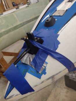
I’ve had discussions with various builders (specifically Dave Berenholtz) on the topic of having a good sized diameter bolt or pin to allow for securing the nose of the plane with heavier weights when its needed to have the nose raised all the way up.  I talked with Marco about how he uses the nose gear actuator, but since my nose gear fairing is a bit wider than his and free-floating I felt more comfortable just putting in a simple hardpoint on the aft side of the taxi light well.

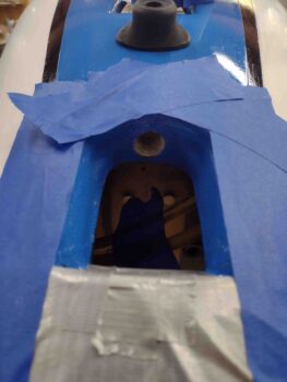
I actually used the wing bolt hole 5/8″ spot face tool to make the final hole for my brass 3/8″ bolt insert.

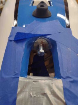
I taped off the interior open face of the threaded 3/8″ brass hard point, and then prepped the hole.  I used grease on a 3/8″ bolt that I placed through a taped-off (mold release) thin aluminum washer that I found in my scrap pile, in turn the bolt was threaded into the 3/8″ insert.

Since my spot face was a bit dull, the resulting hole was a bit oversized.  So I cheated and stuffed in a couple of plies of wetted out glass before slathering flox into the hole, then inserting the 3/8″ threaded insert slathered with flox as well.  As you can see below, I then wedged some small clamps into place on each side of the protruding bolt, pressed up directly against the oversized aluminum washer.

I used MGS 335 here with fast hardener, and here’s the results a few hours later.

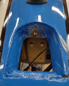
I removed the bolt and washer and spent a good 20 minutes cleaning up the excess flox and glass around the perimeter of the 3/8″ brass insert.  I’ll sand the area after it cures fully and touch up the blue paint.

Here’s another shot of a final test fit with the 3/8″ bolt.  This particular bolt is 2-1/2″ long… clearly I could use one another inch longer, or even an eye bolt, to secure/tie off a weight to.

My final task of the evening was extracting the nearly fully cured Oxygen bottle mounting cradle sleeve, side 2, off the bottle.  This is always a fun-filled endeavor and took a bit of effort to accomplish.  Once off however, with the O2 bottle all cleaned up, it looks like it will work just fine.  I’ll note that I’m working the O2 bottle mounting now since once the bird is flipped back upright this will be a prerequisite task before closing out the strakes.

With that, I called it a night.

Chapter 23/25 – Fuselage paint touchups

I started off this morning with my cup of coffee and some research/inventory of required hardware to connect up my external vernatherm and hopefully attach it to the engine mount.  This effort is copying Nick Ugolini’s method of eliminating the need to block off the oil cooler in the winter by adding another, external vernatherm at a point in-between the engine and oil cooler.  In a bit of irony, I had an external vernatherm on hand when I bought it to use for Nick’s original oil heat system design, that he then upgraded to a much better version later on… so I had a spare laying around.

I then finalized and pulled the trigger on an Aircraft Spruce order, that included a manifold block and Adel clamps for the motor mount to attach the various respective/individual engine sensors… in my quest to make the engine easier to install/remove as needed.

Out in the shop I finished taping up the landing light lens and various edges along the bottom of the nose and fuselage to allow me to do some touchups/additions with the blue paint.

Here we have the taped up landing light lens with the blue touchup paint applied… I went a bit rogue and touched up the upper (aft) side of the lens with a fairly dry application of paint.

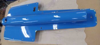
I also touched up/added a bit of blue paint in and around the nose gear, including the front of the NG5 plate, extending the blue back a bit on each side of NG5 to cover up the bits of white showing when the nose gear is closed, and —going roque again!— I got risky and touched up the edges of the nose gear doors now since I had plenty of paint (even though I mixed up like 2 grams worth).  Lastly, I also did a bit of touch up on the fuselage side of the RAM air scoop, and the RAM air scoop/hell hole cover itself.

With the blue paint applied and drying, I then got busy re-taping up the Mountain High O2 bottle in prep for laying up the second half of the composite cradle mount.

As before, I laid up 2 plies of UNI and 2 plies of BID for the second half of the O2 bottle composite cradle mount.  I then peel plied the layup.

To be clear, once I combine the two halves of the cradle mount, I will then use a hole saw to make some rather large lightening holes… this is the reason why I used 4 plies in creating the mount.

I used slow hardener and it was getting late, so I left the layup to cure overnight.

Chapter 13/25 – Gear doors installed

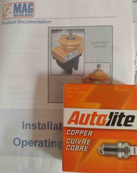
I started off this morning answering an age old question —literally, for this build— What spark plugs do I need to use with my P-Mag ignition system?  Well, I deferred to my good friends over on the VANs Aircraft Forum site and found the answer lickity-split:

Autolite 386

Why these guys?  Well, considering that I’ll be swapping these out every year during the condition inspection, and that the feedback from the RV drivers are virtually flawless… combined with the fact that they are dirt cheap, I didn’t see ANY reason not to go with them. In this current world of crazy prices, I picked up the box of 4 below for less than $10.

Oh, and one more huge benefit is that they are literally tractor spark plugs, so they have 18mm threads which clearly eliminates the need for plug adapters.

Out in the shop, I got busy installing the nose gear doors.  There is one countersunk screw on each door that secures the door opening/closing spring to each door.  These needed some attention to get the screw depth just right, and after that, the install was pretty much just finding the right washers and nuts to secure these things in place.  Well, and a minor bit of razor blade work to clear out some excess paint around the door perimeter edges on the nose side.

I’ll add that the edges of the nose gear doors need some touching up on the blue paint, but again, I’ll use gravity as my friend and hit those when the fuselage is upright.

You may note that I also mocked up the aft-facing wide angle video camera mounting nub just aft of the nose gear wheel well.  I worked on the interfacing/mating surface of the video camera mounting nub to remove some excess paint and smooth it down flat a bit.

I won’t actually silicone RTV attach the video camera mounting nub until after the plane is upright since I’ll need to make sure the camera is oriented correctly as its all mounted in place.

My last task of the evening was to re-attach the lower sound insulating foam in the Hell Hole that had pulled up a bit from the glass surface.  I took the accessible sound foam pieces outside and hit them with a coat of 3M Super 77 spray glue before then spritzing the aft side of the GIB seat in the Hell Hole with the same (ensuring all the nearby painted areas were protected).

After allowing 5-10 minutes for the glue to tack up, I then reattached the foam pieces and they stuck like a charm.  Thus, I am happy to report that all is good with the majority of the sound deadening foam in the Hell Hole.

Again, pressing forward!

Chapter 13/25 – Final RAM scoop install

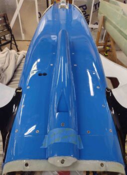
Over the last few days I’ve very carefully sanded down the edges of the RAM air scoop/hell hole hatch cover to allow for it to fit nicely in the outline on the bottom of the fuselage.  Here’s a shot just prior to the first of three sanding sessions.

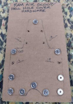
Removing all the screws and CAMLOCs each round to sand the RAS/H3 cover I decided to take 15 minutes to make me up a hardware holder card out of cardboard.  These make life infinitely easier for any component that has a lot of screws and/or CAMLOCs, as I also did the same for my wheel pants.

With some other stuff going on, it took me a couple of days of finalizing the perimeter edges as well as the countersink holes on the RAS/H3 cover, but here it is in its final mounted state.  I’m very pleased with how the hardware is sitting near-flush with the skin surfaces.

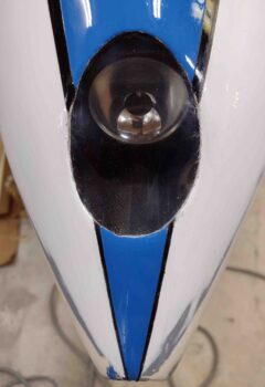
I also spent some time very carefully removing the tape from the nose landing light lens and then carefully trimmed the perimeter of the lens to clear out any stuck tape and invasive micro bits.  I’ll clean up the edge a bit and carefully re-apply paint to spiffy it up… In doing so, to make gravity my friend, I’ll do the front (lower) edge while the fuselage is inverted, and the aft edge once the bird is back upright to avoid having the paint attempting to run down onto the lens.

I’ll note that a lot of these tasks I’m doing right now are finicky, nitnoy finishing tasks that take a good bit of time in the iterations to get it right to call it as close to final completion on these components as possible.

Moving forward!

Chapters 22-25 – Big decisions… a long time coming

I’ve made a significant number of big decisions on the build over the last number of months, with the last few culminating specifically last week when I helped Marco out with his first flight after he installed his Silver Hawk fuel injection system (same that I have) to replace a failed Ellison throttle body.  His flight went well and I picked up a few key tips.

Seeing Marco’s finished firewall, I took note of his goal to easily be able to remove the engine from the aircraft with minimal hassle. I find this especially valuable towards the end of this build when I may need to remove and mount it a few times for cowl fitting, finishing, painting, etc. This included Marco’s mounting the various engine sensors on small manifold blocks attached to the engine mount tubes, as well as very cleanly managing all the electrical connections through a connector on the firewall.  This helped answer some design questions I had in my own mind, especially since I got to observe how these features worked operationally.

Now, both Marco’s bird and Chris Cleaver’s bird are beautiful Long-EZs, but my dilemma with trying to decide what to do with my boat-painted bottom fuselage was answered when I scrutinized the finish on both their EZs… I realized that neither paint finish was perfect, and that I needed to focus on the main goal: get this bird in the air.  Again, that’s not to slam their finishes at all, but I had to be realistic and just realize that the bottom of my plane is not going to win any beauty contests.  That’s the price we (or I at least) pay for experimenting!  And I certainly don’t want to redo it all and add months to the build (yes, I realize that’s an ironic statement given I’ve been away from the build for a good bit).

After returning home, I took about a week to update a good half dozen electrical & connector diagrams, especially given that all my smaller gage engine wires will run through 2 connectors on the firewall.  I determined and verified all the firewall-transiting wire runs, what wires would go to which connector, and then ordered the connectors and associated pins and sockets.

Since my 11×17 printer had sat dormant for 6 months, I also needed to spend a good few hours cleaning and getting that beast online.

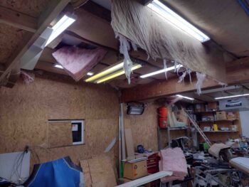
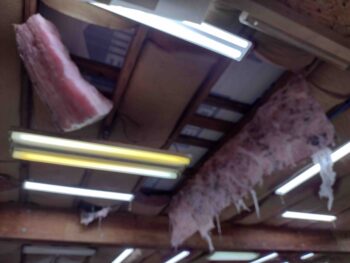
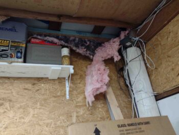
Speaking of cleaning, I also spent a good 4 days cleaning the shop, where the squirrels had apparently moved in and decided to have a few parties… a real mess.  Here’s a few pics of the calamitous scene I found:

Dust pert near everywhere!

We get a lot of rain here, and with my both my air conditioner and lights off, the insulation can get over saturated with condensation and drip down on whatever is below… here being the fuselage and strakes.  Looks bad, like rust almost, but it is just water collecting with lots of dust.

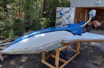
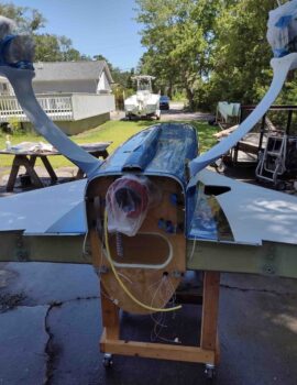
Thus, I rolled the fuselage outside and washed ‘er down good.

Another shot (note my new toy, a boat, in the background… yes, I strayed a bit while off the build!)

As the fuselage, wings, canard, cowling, etc. dried, and while the bays were clear, I tacked the insulation back up in place that the partying squirrels had knocked down…. it’s a constant battle trying to patch holes to keep them out!

I also gave the bays a good sweeping and a bunch of dusting of course.

Ok, ready to start building again!


Chapter 3 – Mill CNC Operational

Yes, today was all about getting the milling machine CNC capability online.  Which I was actually successful in doing.

Yesterday I spent much of the day messing about with reinstalling the X-axis ball screw and mounts to allow the stepper motor to actuate the table left and right without getting a Drive OK Fault Alarm… which, while I’m glad the Drive OK Fault Alarm is working properly, I certainly don’t want to see one every time I command a +/- movement on the X axis.

With the drive axes finally working in all directions yesterday, today was all about finalizing the CNC install tasks with a couple of bench tests.  And then documenting my mill CNC efforts up to this point in a video.

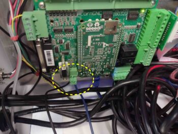
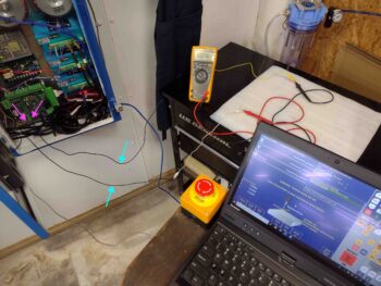
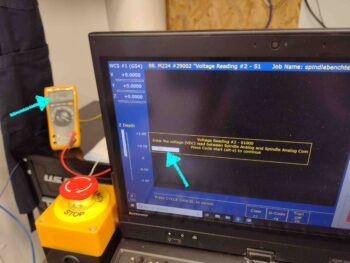
My first task of the day was accomplishing a spindle speed output test on the Acorn CNC control board.  This involves hooking up the Fluke multimeter to the 0-10 volt “VFD” output (I mistakenly call this an “input” in the video…) on the Acorn board.  Since my meter leads wouldn’t fit in the cabinet, I connected two lead wires up to this output.

Here are the 2 Acorn board VFD output wires connected to the Fluke multimeter.

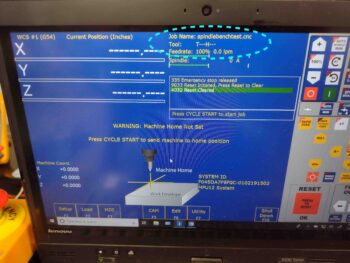
I then loaded up the spindlebenchtest.cnc program into the CNC12 software.

And ran the program.  The program has the Acorn board kick out a series of 4 discreet voltage values which you read off the multimeter display and then enter into the program entry box, one at a time.  This confirms the voltage values between the Acorn board and the CNC12 program to verify all is correct for the VFD voltage output.

This is a prerequisite task that needs to be completed before wiring up the KBSI-240D spindle speed/direction control board, and I figured I would simply get it knocked out now.

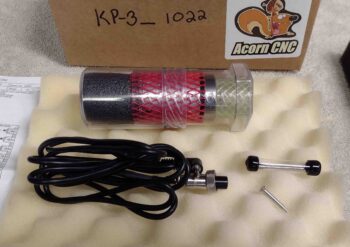
I then unboxed and prepped the KP-3 Kinematic Touch Probe for the bench test that I performed while filming the video.  I figured I would do at least one bench test “live” on camera.

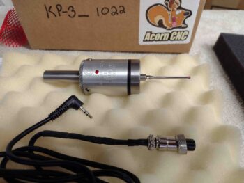
I took the probe body out of its plastic case and then carefully installed the actual probe stylus into the front/bottom of the probe housing.

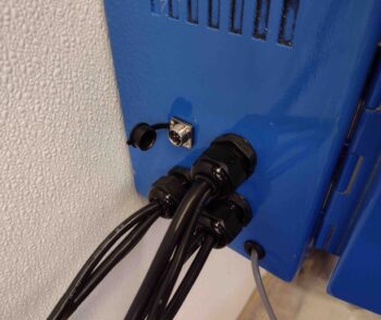
As you can see above, the jack of the probe lead is inserted into the probe body, while the other end is attached to the connector on the outside of the CNC control box, below.

With the KP-3 probe ready to go, I actually filmed the bench test segment first (ah… tricky I am!) before then filming the remaining video footage detailing my mill CNC upgrade machinations.

Here’s the video. It’s a bit long, but I think informative.  Enjoy!

After filming the video, I then of course had a late night of video compilation and editing to get this thing loaded up on YouTube.

Soon I will get back to working on the actual plane… promise!