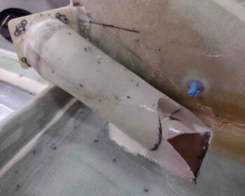
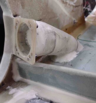
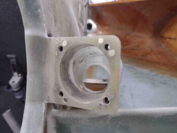
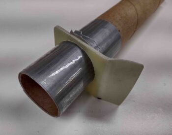
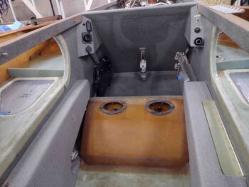
Chapter 21/24 – GIB air vent complete

Today was the annual seafood festival here in Morehead City, NC so I was out and about quite a bit before getting into the shop for a few hours.

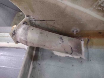
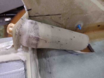
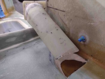
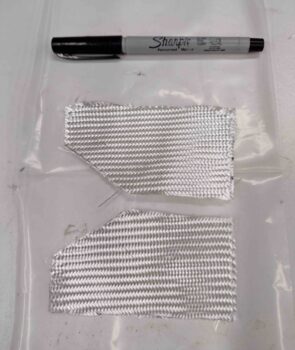
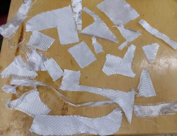
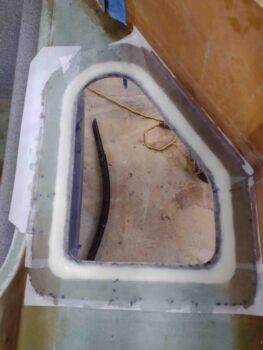
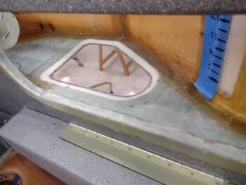
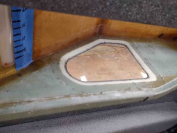
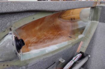
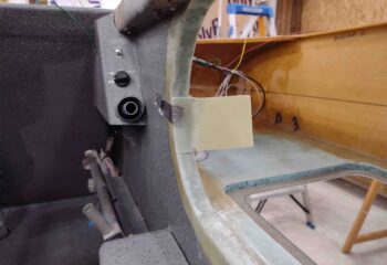
I made a template and then cut the 2 plies of BID before prepregging them.  I then wet out and laid up the BID plies as the final layup to finish the installation of the GIB air vent duct.

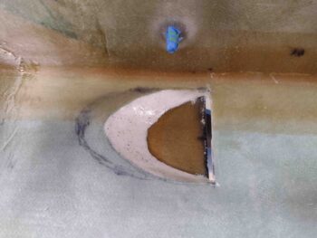
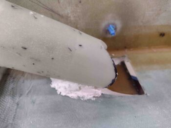
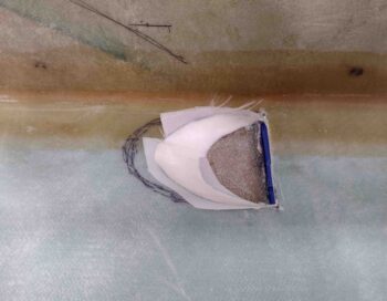
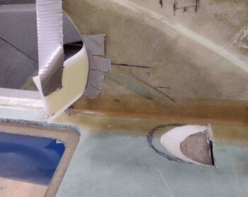
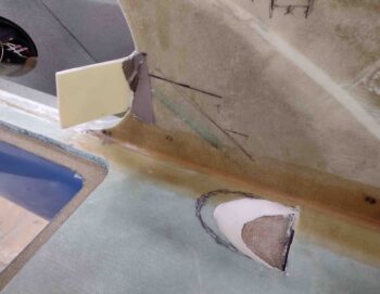
On the duct itself I laid up the 2 plies of BID overlapping onto the edges around the opening.  However, on the forward edge of the NACA duct opening I split the layup… one ply on the inside (top) while the other side overlapped onto the face of the external NACA scoop (underneath).

In between these 2 plies of glass right where they spit into single plies —internal and external— I laid in a bead of micro.

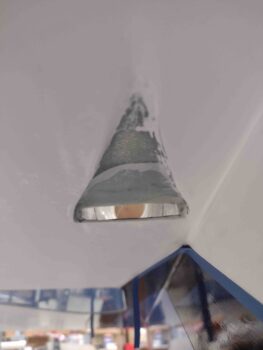
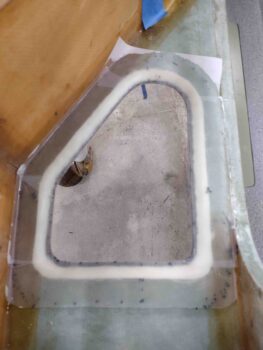
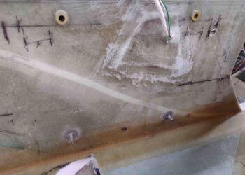
Here we have the external ply laid up on the external face of the NACA scoop.  I then peel plied all the areas that required it.

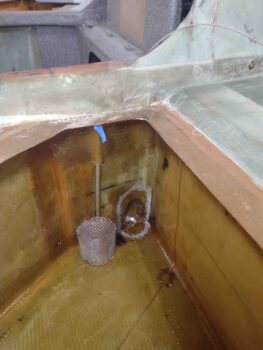
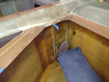
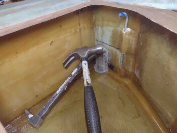
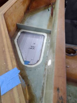
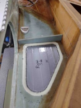
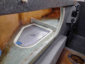
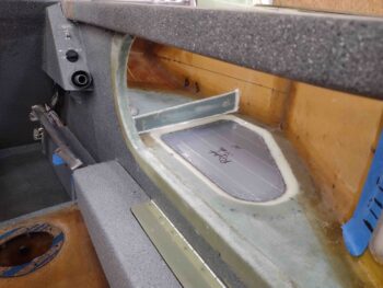
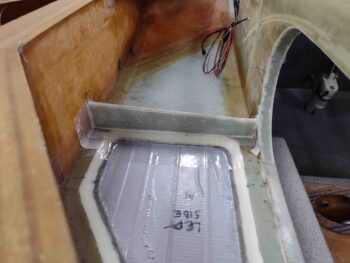
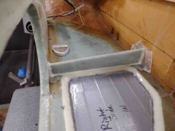
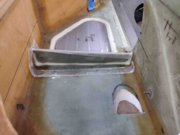
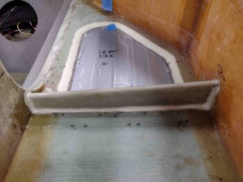
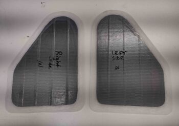
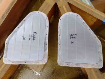
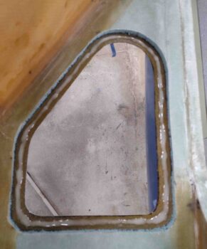
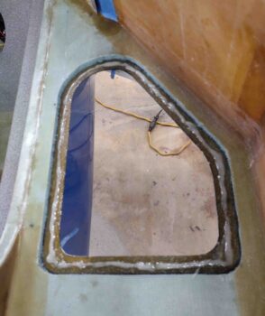
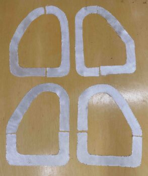
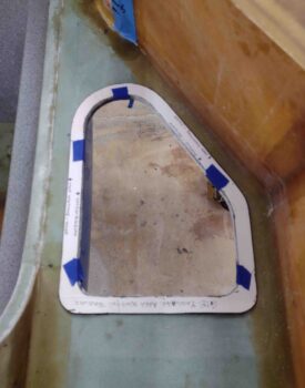
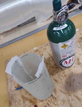
As I finished up the GIB air vent layups above, I had a decent bit of epoxy left over in my cup.  I decided to use this extra epoxy to flox in the fuel tank drain screens.

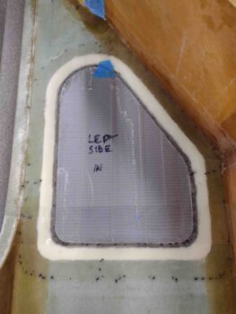
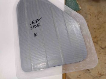
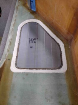
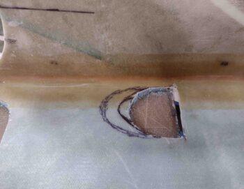
I started by tracing the left fuel drain screen with a Sharpie . . .

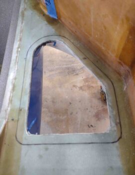
I then sanded the shiny epoxy under the marked line, and then cleaned the sanded areas with acetone.

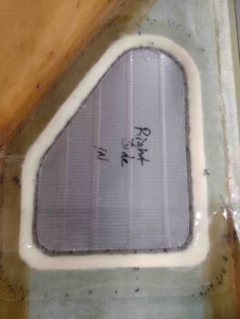
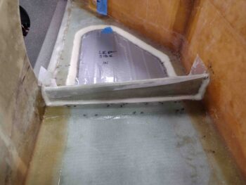
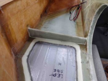
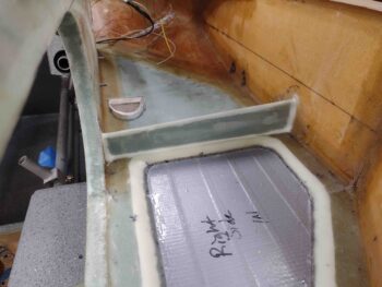
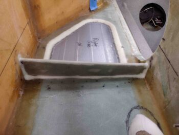
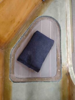
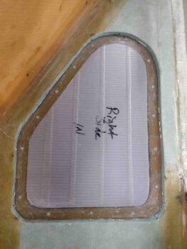
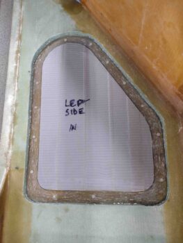
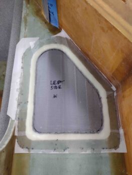
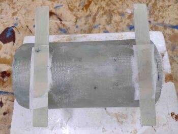
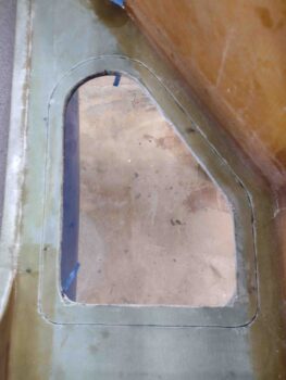
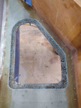
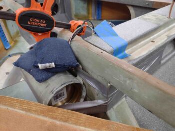
I then used the leftover epoxy to whip up some flox to set the left fuel tank drain screen in place. I then used a taped up block of wood with a shot bag weight to secure the screen in place against the tank side wall and floor.

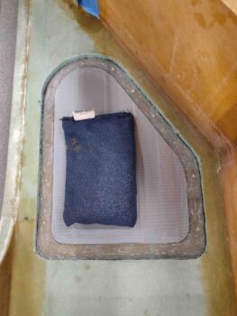
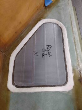
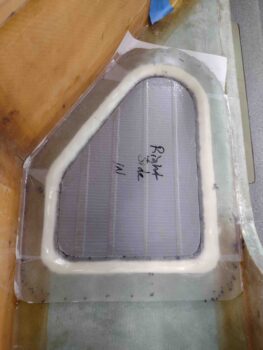
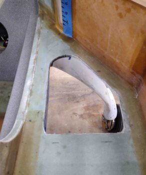
I had just enough flox to do the left side, so I mixed up a bit more epoxy to make up a bit more flox to flox the right fuel tank drain screen in place as well.  I then weighed the screen down a little to press the edges firmly against the tank side wall and floor.

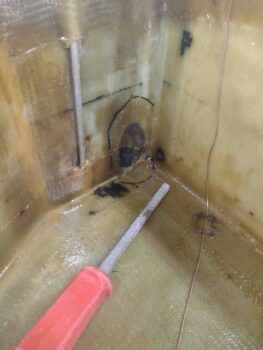
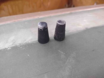
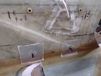
And just so YOU know…. and moreover for MY peace of mind, I grabbed a shot of the two removed protective rubber stoppers that I had in the tanks’ drain tubes to keep dust and debris out.

A few hours later, after the epoxy cured, I pulled the peel ply from the layups.

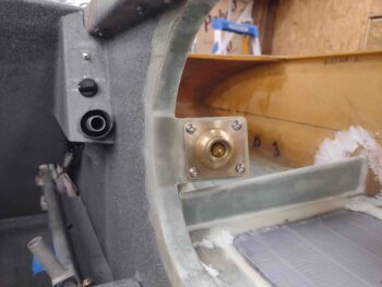
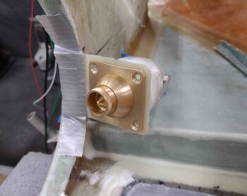
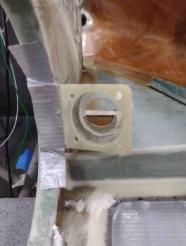
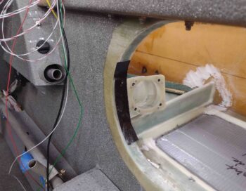
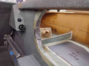
I then installed the eyeball vent with a new set of screws, and with this I’m declaring the GIB air vent install complete.

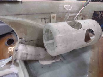
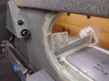
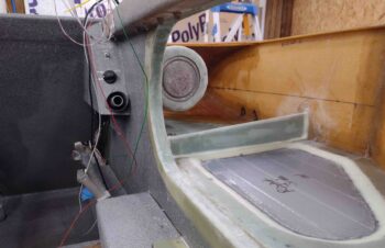
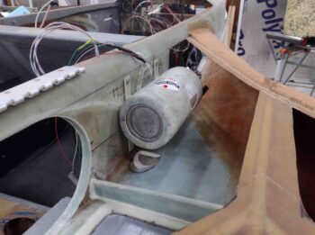
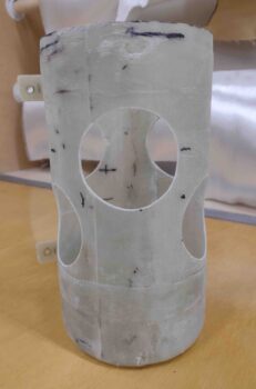
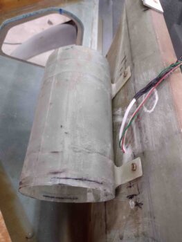
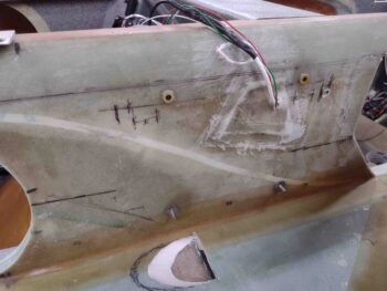
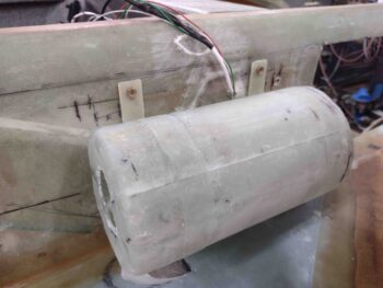
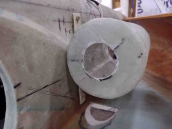
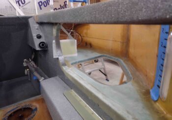
I then installed the O2 bottle mounting sleeve to check the clearance with the GIB air vent duct… which is very little. There is just a hair of space between the two components, but I have a fair amount of meat on the corner of the O2 bottle mounting sleeve to remove a bit to create a decent gap (note the black Sharpie marks which is where I’ll do some trimming).

With a week under my belt since I’ve been back from Rough River, let’s revisit the list of prerequisite tasks that need to be completed before closing out the strakes:

First, the following were completed this past week:
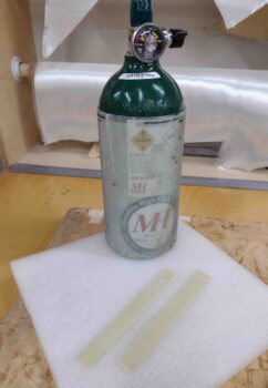
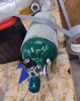
O2 bottle mounting in composite sleeve
Installing main fuel tanks drain screens
⇒ Installing/glassing GIB strake/baggage compartment windows
⇒ Installing/glassing right strake GIB NACA vent duct and eyeball vent
⇒ Installing/glassing GIB strake/baggage compartment cross support mini-bulkheads

That leaves these tasks to be done:
⇒ 
Outboard storage compartments on the top strake side initial tasks
Wiring and install prep main fuel tanks fuel probes

Installing/terminating main fuel tanks vent lines
Cleaning up fuel site gages edges (cosmetic)
Wiring fuel site gages LED lights
Installing/glassing/wiring GIB map light
Designing/constructing/installing left/right fuel site gages video camera mounts
Wiring/installing fuel site gages video cameras
Constructing/glassing/installing left strake RAM air scoop/ducts for oil heat system
Prepping/priming/painting strake baggage and final cockpit areas

Chapter 21/24 – GIB vent near final

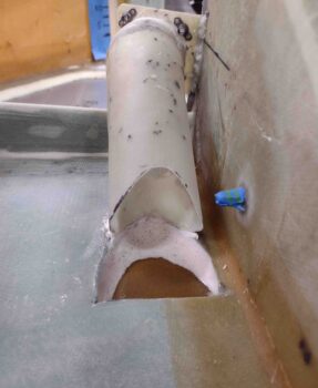
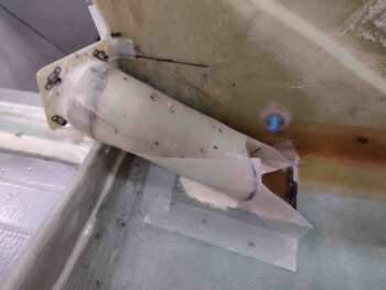
My very first task in the shop this morning was sanding the inside of the NACA scoop to smooth out the micro and transition between it and the underlying glass.  The dark speckles are due to me cleaning it with acetone beforehand and it pulling in some of the black Sharpie ink into the pours of the micro.  Oh well…

I then applied and left the thin application of epoxy to cure.

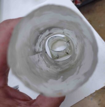
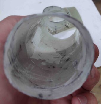
I spent about 20 minutes cleaning up the layup that secures the second duct segment to the first.  Since there is an internal edge from the initial duct form fitted into the second/longer duct, I applied some micro inside the duct and covered it with peel ply.

I then test fitted the GIB air vent mount and duct in relationship to the NACA scoop opening.

Here’s another shot of the test fitting.  I then slowly started cutting away the NACA end of the duct.

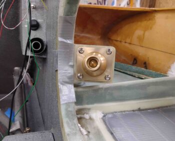
I wanted to see how the entire assembly would look in general with the gold eyeball vent installed, so I temporarily set it in place.

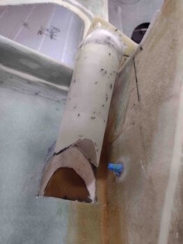
With the eyeball vent removed, you can see a fairly straight shot —even with the slight duct dogleg— between the eyeball vent and the opening of the NACA scoop.

After a good 45 minutes or so, I had finally trimmed the GIB air vent duct to the shape I wanted, that gave me the best interface with the NACA scoop opening.

I should note that I was a hair off on my floxing and glassing the forward duct segment to the aft one… the resulting gap between the mounting flange and the curved sidewall opening when the forward duct was aligned with the NACA opening was a bit more than I wanted. Although I hate doing this, I took the heat gun to the flange and warmed it up enough where I could manipulate it to then narrow that gap.  My heat trick didn’t eliminate the gap completely, but it did reduce it significantly to a point where I was comfortable with it.  Moreover, my issue with the gap wasn’t really appearance, but rather weight and strength… I didn’t want a larger glob of flox having to take up the space in the gap and do most of the work of holding the mount to the sidewall.

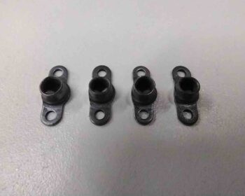
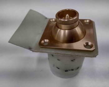
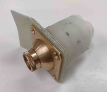
With the initial fitting out of the way, it was now time to mount the nutplates to allow for securing the GIB eyeball vent assembly to the mount/duct.  I used the smaller footprint nutplates but even then the space was so tight I ended up grinding off the small flange on the side of each nutplate.  If you look closely below, the left sides of the nutplates are shaved off.

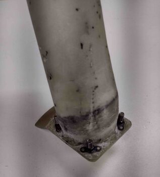
I then mounted the nutplates to the flange on the GIB eyeball vent mount… which was a very tight fit. (Note the micro under peel ply in the opening of the duct).

My riveting of the nutplates to the eyeball vent mount flange was NOT pretty or done with style, since getting the rivet squeezer into place was challenging lacking the space.  But the nutplates work, are functional, and I’m pressing forward!

Again, I wanted to see how the eyeball vent would work and ensure the screws all fit well so I mounted the eyeball vent to the mounting flange with button head screws.  I’m very happy with the outcome so far.

With nutplates on the mounting flange and my configuration looking good, it was go time. I floxed the mounting flange (aft) to the curved sidewall opening, using just a small blob of 5-min glue in the center for a really fast attachment.

Concurrently, on the forward (NACA scoop) end I piled up some dry micro in a U-shape leaving just about a 1/4″ square area open right where the duct actually contacts the strake/baggage compartment floor.  I also placed a small dab of 5-min glue on the bottom edge of the duct to secure it to this aft edge of the NACA scoop opening.

[I had thought about using pour foam in lieu of the dry micro, but I saw that building dams and shaping the foam would be a lot more challenging —especially on the fuselage wall side where it’s tight— than just using dry micro here.]

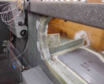
After holding the GIB air vent mount & duct assembly in place and tight against its contact points for a few minutes, I then cleaned up the area around the mounting flange.   As you can see in the pic I also used a strip of black Gorilla duct tape to secure the aft mounting flange in place against the curved inside fuselage sidewall.

For securing the forward intersection between the duct and the strake/baggage compartment floor, I had measured (and test-fitted) a template to create 2-ply BID tapes for the job.  I then prepregged the 2-ply BID pieces and wetted them out.  The Sharpie pen is just there to show the size of the BID plies.

I then applied the BID tapes to the junction between the duct and the strake floor. This of course cleaned up the initial jagged shape of the dry micro and smooth it out.  I added a ply of BID on the very aft side to cover a narrow strip of dry micro that was peaking out, and then I peel plied the majority of the exposed edges of these BID plies… to eliminate the possibility of hands/arms/fingers getting shredded when putting stuff in/out of the baggage compartment.

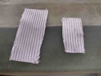
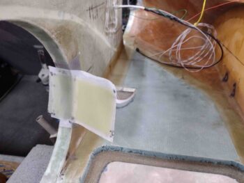
On the mounting flange attaching the assembly to the sidewall, I grabbed 2 pieces of BID out of my scrap pile to use… the larger BID piece on the left covered the flange on the outside corner and overlapped onto the inside fuselage sidewall.

The smaller piece of BID on the right went into the inside corner on the outside wall of the fuselage and can be seen in the pic above with a small piece of peel ply on it.

I then peel plied the outside corner BID layup and left it to cure.

A few hours later I pulled the peel ply from the outside corner BID layup that secures the GIB eyeball vent mounting flange to the fuselage sidewall.  I then razor trimmed the overhanging glass and sanded the remaining peel ply goobers to clean it up.

I also pulled the peel ply on the duct-to-strake baggage compartment floor/NACA scoop layups and cleaned it all up as well.

I realized I hadn’t gotten a good pic of the dry micro filler so I added this shot here.

Finally, I pulled the peel ply and sanded the inside seam of the duct segments to smooth out the internal contour of the GIB air vent duct.

I have to add/shape some micro inside the added BID plies on each side of the NACA scoop. I then have one more 2-ply BID layup to close out the NACA intake scoop and this GIB vent addition will be complete.  I plan on knocking that out first thing tomorrow.

Chapter 21/24 – More GIB vent

Today I focused primarily on constructing the duct between the GIB eyeball vent mount and the NACA scoop (on bottom strake skin).  My plan was to accomplish this in 2 phases.

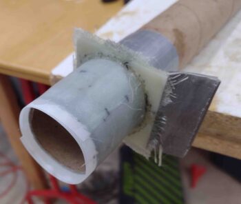
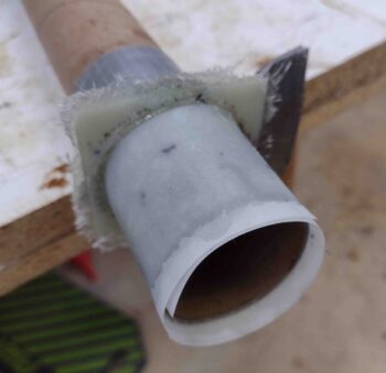
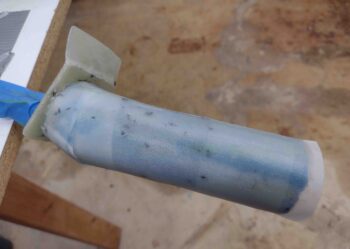
With the angle of the eyeball vent pointing at the center of the GIB there is a slight dogleg required in the duct, so the first phase was simply to create a duct tube coming off the aft side of the GIB eyeball vent mount.  I taped up a paper towel roll and biased it a bit so it was angled slightly inboard and slightly down.

For the glass —both UNI and BID— I simply dug into my scrap pile for the 2-ply layup to create the duct.

I laid down a 2″ ply of peel ply first, then laid up 2 plies of glass using my scrap glass.  I then peel plied the outer surface of the duct.

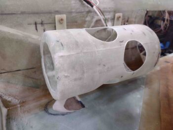
While the GIB vent duct layup cured, I cut the last lightening hole in the O2 bottle sleeve mount on the aft end.  I then installed the mounting sleeve in the bird.

I then slid the O2 bottle in place to see how it looked.

Here are a couple shots of the lightening hole at the aft end of the O2 bottle mounting sleeve.

I’ll note that this fiberglass O2 bottle sleeve mount is way lighter than the metal band system that came with the O2 system from Mountain High.  I’ll have final comparison weights once I get the velcro straps attached to the front end for securing the O2 tank in place.

A few hours later, I pulled the peel ply and razor trimmed the added duct segment on the GIB eyeball vent mount.

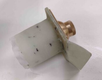
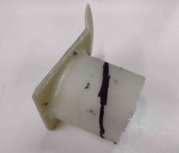
Here’s a couple more shots of the added duct segment on the GIB eyeball vent mount.

I then took some time to figure out the angles I needed to get the duct from this mount down to the NACA scoop.  After my assessment, I then marked the added duct segment to be trimmed.

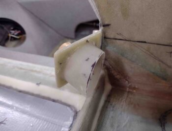
After I trimmed the added duct segment on the GIB eyeball vent mount, I mocked it up in place inside the fuselage.

I then spent a good hour+ creating a mold for the second segment of the duct that will connect to the NACA scoop… Phase 2.  After I glassed it (using scrap glass), I then peel plied it.

Again, a few hours later I pulled the foam mold, tape and peel ply to reveal a fairly decent duct segment.

And here’s a shot from the other end… note that I drilled the 4 screw holes in the GIB eyeball vent mount flange.

I actually floxed and glassed the two pieces above back together but failed to get a pic of it… I’ll grab one tomorrow as I hopefully finish installing the GIB fresh air eyeball vent and duct (Phase 3).

Chapter 21/24 – GIB Eyeball Vent

I had to get some personal stuff done today, so I didn’t get nearly as much done in the shop as I would have liked… although I did get nearly 3 hours of work in.

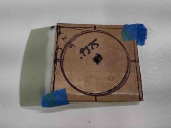
I started off by taping my original cardboard template to the GIB eyeball vent mount to find the best spot to drill the center hole.

Which I then did… although I ended up skooching it over about 0.070″ to the left, as shown in the pic below.

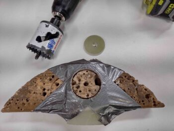
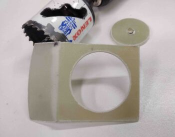
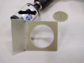
I then taped the GIB eyeball vent mount to a scrap block of wood and used a 1-3/4″ hole saw to drill out the eyeball vent mounting hole.

Here we have shots of both sides after I removed the mount from the wood block and cleaned up the edges.

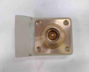
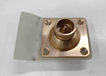
The outside diameter of the inside eyeball vent body is nearly 1-7/8″, so I spent a good 10 minutes hand sanding the mounting hole to widen it out just a bit.  I then test fitted the GIB eyeball vent into the vent mounting tab.  I also rounded the exposed corners as to reduce any sharp snags to the GIB’s arms/hands reaching into the baggage compartment.

I then assessed if my original planned spot was good by taping the mounting assembly in place.  My mock up confirmed that the vent is where I want it.  [I actually spent a good half hour sanding down and cleaning up the glass on the mini-bulkhead layups prior to proceeding with my GIB air vent mount mockup].

Tomorrow I’ll work more on the GIB air vent mount and ductwork, but before I left the shop I went ahead and drilled a few lightening holes in the O2 bottle mounting sleeve using a 2-1/4″ hole saw.  It only reduced the overall weight by just under an ounce, but like Burt says: every gram of weight reduced is a good thing!

I’m inching closer to being done with all these strake/baggage/tank prerequisite tasks in order to close out the strakes with the top skins.

Chapter 21 – Baggage area bulkheads

Since I went with the GIB elbow room mod in my strake baggage area by extending the BAB bulkhead much farther aft, I decided to kill two birds with one stone by installing a mini-bulkhead just forward of each GIB strake window.  Beyond adding reinforcement to the BL 23 rib at about mid span, the second feature of these mini-bulkheads is simply baggage retainment… as in keeping anything placed in the main baggage storage area from creeping back over the GIB windows.

Starting off, I reapplied the protective tape on each GIB strake window.  I also added a strip of clear tape across the front edge of the strake window, over the existing protective tape.

After sanding the areas where these bulkheads would get glassed to, I then sanded and final tweaked each of the 3/8″ thick PVC foam mini-bulkheads to fit them into place on each side.

Here’s a couple more pics showing the fitting of these mini-bulkheads in the strake baggage areas.

I micro’d the mini-bulkheads in place and then applied the leftover wet micro onto as much of the foam surfaces that I could.

I made up 2 sets of prepreg with an underlying ply of UNI and a top ply of BID.  I then wet out the prepregged glass and laid them up onto the mini-bulkheads, overlapping about an inch onto the surrounding glass structures.

I then peel plied the layups, focusing primarily on the aft sides of the mini-bulkheads.

Here we have the front sides of the just-glassed mini-bulkheads.  Note how I don’t have a lot of peel ply on the front side of these layups.

Since I used MGS 335 with fast hardener, a few hours later I pulled the peel ply to reveal the freshly installed mini-bulkheads.  They look good and I didn’t see any significant issues.

Again, here we have the front sides of the freshly installed baggage area mini-bulkheads. The incomplete application of micro on the foam surfaces —since I only used whatever was left in cup— gives the appearance of some delams in the layups, but that’s not the case and the glass is securely attached to the underlying foam.

I’m very happy with how these turned out.  Now I can continue to press forward knocking out other prerequisite tasks before closing out the strakes with the top skins.

Chapter 21 – GIB windows installed

A day after getting back from Rough River I wanted to get right to work, with the goal being to finalize the GIB strake windows install.

I started out by hitting each edge —inside and outside— with a sanding drum on the Dremel Tool.  I then hit it with 60 grit and finally 220 grit.

It may be a bit difficult to see the sanded edges above, so I grabbed another shot of it with a darker background.

I then drilled holes around the perimeter of each GIB strake window pane to allow a better grip on each window by creating flox “studs” in each hole.

I then whipped up some flox using MGS 335 with fast hardener and laid down a bead on each window flange, one at a time.

I then set each window pane in place and weighed it down with ~2-pound diving weight bag.

After about an hour I pulled the exterior protective tape panel on each window and cleaned up any excess flox that had squeeze out on the exterior perimeter of each strake window.

As the GIB strake window pane flange flox cured, I used my window template to cut 2 sets of BID with seams at 90° to each other for 2 plies total to secure the windows in place.

It may be hard to see in these pics, but I then mixed up some wet flox to fill in the gaps around the window panes to more fully secure the panes to cutouts/sides in/of the strake window cutouts.

A big reason I did this was to ensure that from the edges of the window panes down along the opening flanges I wanted secured with flox since from here on out I would be using dry micro for the transition of the strake baggage floor (~3/8″ thick) down to the surface of each window pane (~1/8″ thick).

I then whipped up some dry micro and laid/shaped it in along the edges of the windows to create a sloped transition from the top of the strake baggage floor down to the edge of the window panes, leaving around 1/4″ of the window’s surface to secure the glass to.

I then laid up the 2 plies of BID on each window pane to secure the windows in place. After laying up the BID plies I then peel plied the layups.

After a little over an hour, with the epoxy mostly cured, I then pulled the protective tape panels off the windows and cleaned up the edges of each window to remove any overhanging glass and micro.

A few hours after I pulled the protective tape and cleaned up the layup’s window edges, I pulled the peel ply and cleaned up the layups.  With that, I’m calling the install of the GIB strake windows complete.

After completing this significant milestone on the build, I called it a night.

Rough River 2022!

Well Marco and I decided to get the band back together and hit the road… to Rough River 2022!

I arrived at Marco’s place later in the evening Wednesday and enjoyed yet another awesome meal cooked by his beautiful wife Gina.  We gabbed a bit before hitting the rack to start another adventure the next day to Falls of Rough State Park, Kentucky… aka Rough River.

We arrived at Chesapeake Airport around 0930 with a plan to launch around 1000.  We packed our bags (the bigger ones going into Chris Cleaver’s Long-EZ), preflighted the plane, closed up the hangar and were ready to go right about 1000.

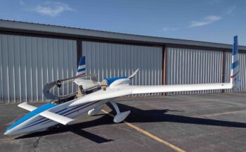
I grabbed a few preflight pics below before we climbed in to take to the skies.
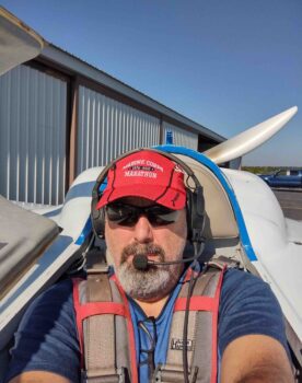
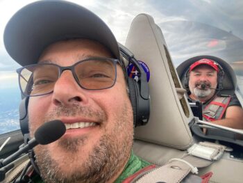
After climbing in and strapping the plane on (you essentially wear a Long-EZ!) I grabbed a selfie and another shot looking forward at Marco just buckling up.
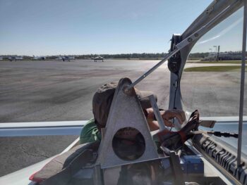
Our taxi out to the runway didn’t take long since we had NO RIGHT BRAKE… all we could do in front of the hangar was spin circles to the left.

No good.

So with Chris’s help we pulled JT back into the hangar and spent a good 45 min bleeding the right brake.  Then Marco took ‘er out for a spin and tested the brakes.  All seemed good so it was go time.  We packed back up in the plane and headed for the runway.

However, this time the plane was pulling severely to the RIGHT and Marco had to get some higher RPMs to keep it on the centerline.  Again, no good.  We did a high speed taxi back down the runway and after arriving the parking ramp had to spin 3 brodies before finally being able to get on a track back to the hangar.

When we pulled up to the hangar, Chris was already there and out of his plane.  He ran up to tell us our right wheel was smoking a lot.  We got out of the bird quickly, and while Marco ran to grab a drill to remove the wheel pant screws, I judiciously poured water into the seams of the wheel pant to cool down what I could.

Apparently the right brake had seized up.  With the wheel pant off we set up a huge shop fan to cool it down.  Then we bled the brakes again.

But just as all seemed fine, and we were ready for launch attempt #3, we noticed a puddle of brake fluid under the right brake caliper.  Ugh!  Under further inspection we realized that the brake caliper o-ring seal had most likely gotten fried from the heat, so we replaced it with one that Marco luckily had on hand!

With the right brake essentially rebuilt, after a bit of discussion we decided to leave the wheel pants off in case we needed to work on either of the brakes (clearly and mainly the problematic right brake).  We also packed up the extra brake fluid and tools to bleed the brake if need be.

With that, we finally launched out of Chesapeake mid-afternoon.  We had some clouds to dodge and a fairly good headwind, making our trip to Rough River about an hour longer than usual.
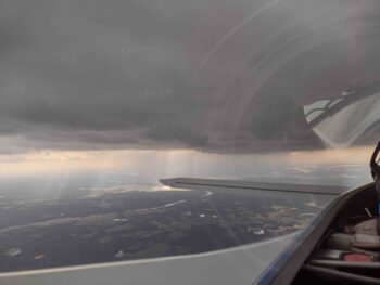
Still, it was great flight and we made it into Rough River a little bit before the sun went down.  Here’s a shot shortly after landing at RR.

We met up with Terry Lamp, Mike & Marcy Toomey, Rodger and the gang and hung out with them for the night before heading back to our cabin and hitting the rack.
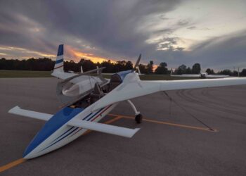
The next day, Friday, Mike Beasley arrived to RR, with his usual penchant for the dramatic (nice go-around buddy!).  This was the first time I had seen his bird “Scooter” other than in pictures.  What a great Long-EZ and awesome job he did on it. Of course I scoured it looking for any final build tips I could find before finishing my own build.

Here I noted the aft edge of the baggage pod pylon and the intersection of it with the aft pod cone.
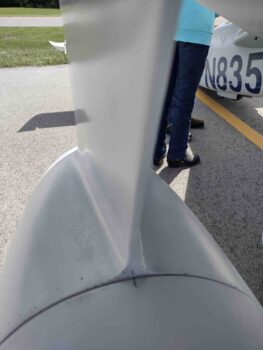
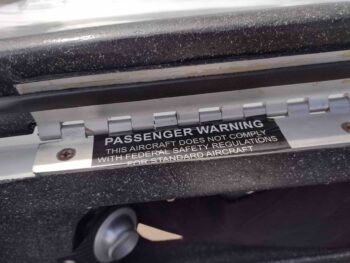
I also really like where he placed his mandatory Passenger Warning sticker.  Very visible but out of the way… good use of space.
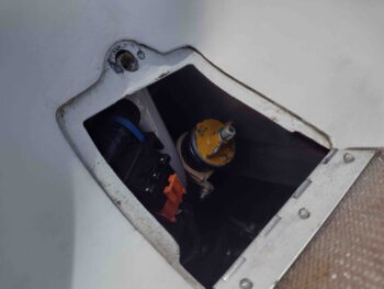
Mike’s oil door was preset in his upper cowling and a little forward of the actual dipstick, making him get creative to make up a flexible oil dipstick.  Quite ingenious really.
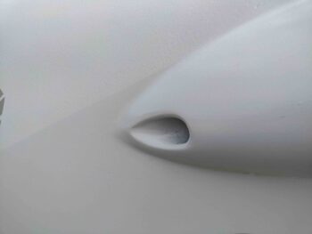
I also took note of the shape and position of his pilot fresh air vent intake at the left strake intersection with the fuselage. Mine is on the right side, and it’s always good to get ideas.
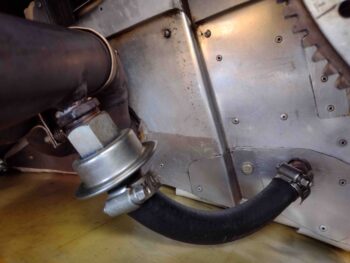
Talking with the Iowa canardian contingent, Ron White and Terry Sherman, I had a good discussion with them on how they set up a one-way valve attached to the exhaust pipe to pull a slight vacuum on the crankcase vent line.  This not only provides better pressure control in the crankcase, but all the small amounts of oil, etc. simply gets burned up as it exits the exhaust.  Very clean and less unsightly residue on your prop.

Here’s Ron White’s setup.
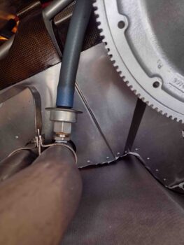
And a couple of shots of Terry Sherman’s setup as well.  Very crafty and something I may very well copy.
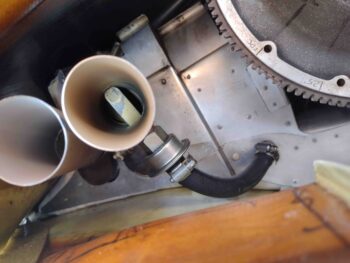
I met Howard Caulk from Baltimore for the first time (that I remember) this Rough River. He has a crazy number of the same components in his Long-EZ that I do, resulting in me spending a good bit of time at his bird picking his brain.

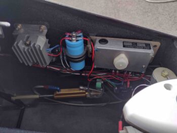
Below you can see both the main voltage regulator for the B&C alternator, and just aft of that (left side) is the capacitor and smaller voltage regulator for the backup SD-8 vacuum pad mounted alternator.  I have these SD-8 components in the GIB headrest, where Howard clearly has his in the nose.
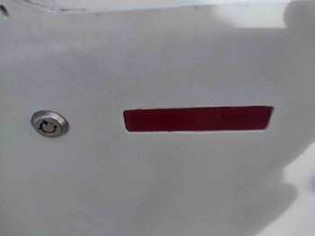
A key nagging question that I’ve had regarding my canopy latch handle is the attachment configuration for the handle lever to the aft and forward latch hook rods.  I think I found my answer by looking at how Howard did his very similar canopy latch handle, as we have here in the pics below.

Finally, this is close to how my canopy latch handle will look from the outside as well.
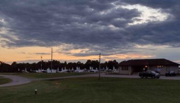
As we were walking back from dinner at the lodge we grabbed this shot.  All in all we estimate there were about 50 planes total at this RR.
Our other cabin mate for this RR 22 besides Mike Beasley, was the venerable canardian, EJ Johnson.  On Saturday Mike took EJ for a ride and I snapped a few shots as EJ climbed into the back of Mike’s Long-EZ.

Here’s a good shot of Mike Beasley’s Long-EZ (aka “Scooter”).
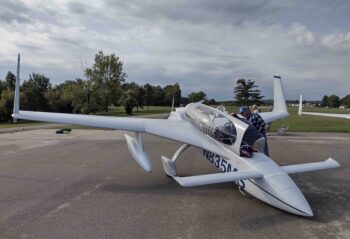
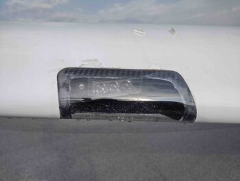
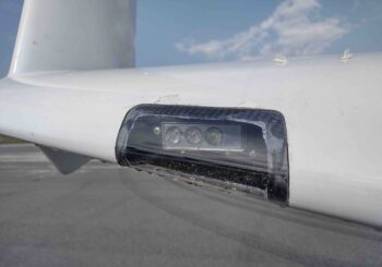
Nick Ugolini showed up in his new-to-him (a couple years now) Cozy IV.  He added the same style wing mounted landing lights as he had on his Long-EZ, so I grabbed a couple shots of those since I intend on following suite.
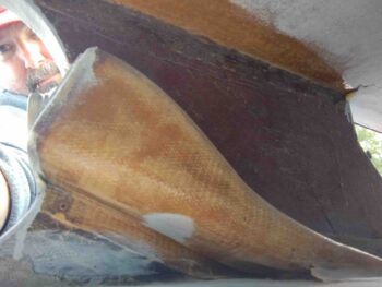
Although I see Chris Cleaver’s bird quite a big since he’s based at Chesapeake with Marco, as I was talking to the builder of Chris’s Long-EZ, Mike Toomey, about the GIB air vent, I took the opportunity to grab a shot of the construction.  I of course am just getting ready to knock this out on my bird as well and wanted any to get as many tips and tricks as I could on it.
I’ll note that I may have gone with a much simpler design on my canopy latch handle setup if I had seen Jim Evan’s Long-EZ beforehand.  This is a very simple setup that doesn’t require a bracket coming off the instrument panel.
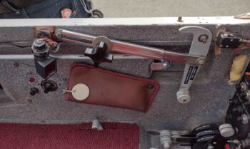
Jim also has a handle in the back seat which is nice to allow the GIB to open the canopy if need be.
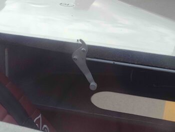
I may have grabbed a shot of this previously, but since again I’ll be adding a forward right hand side latch to my canopy, I wanted to note how Curtis Wray did it on the Long-EZ he built.
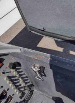
I love the gray and blue paint scheme on Curtis Wray’s built Long-EZ (now with a different owner)… I wanted to capture how he painted his upper cowling.
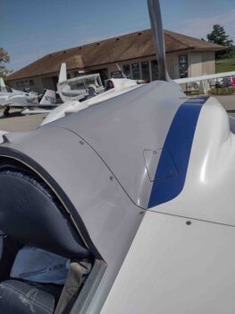
Speaking of paint schemes, I really like the simplicity and color scheme of this Cozy IV… something I could learn from. Ha!
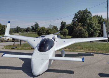
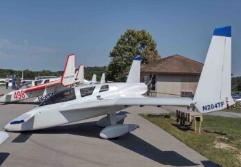
I didn’t meet the owner, but we had a Long-EZ fly in from Canada and I grabbed a shot of how he has his wheel pant venting set up.
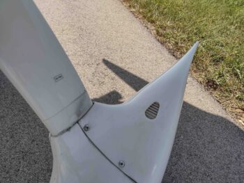
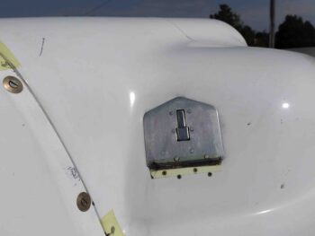
Also, I don’t remember if this was on a Long-EZ or Vari-Eze, but I’m currently very interested in oil dipstick access doors on the upper cowling since I’ll be dealing with that in the near future.
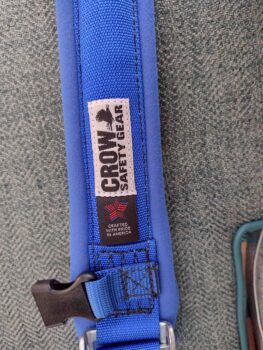
Fred Wimberly sold his Long-EZ and bought a Cozy III.  I hadn’t seen these harnesses before so I grabbed a shot for possible future reference.
On Sunday we all had breakfast before packing up and heading out back home.  Initially the weather looked great on our way from Rough River back to London, KY for some cheaper gas and a quick break.

However, the clouds had other ideas and we had to head north somewhat before finding a break that allowed us to get to the airport.  With Chris in tow —with no IFR capabilities on his bird— we stay VFR, which can be a bit challenging at times.
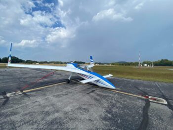
Here’s Marco’s bird tied down at London, KY airport (we heard some thunder in the distance, thus the tie downs just to be cautious).
We had invited Mike Beasley to fly to London, KY with us before breaking off and heading south to Georgia, but he wanted to go as direct as he could.  Oddly enough, as weather events dictated, he ended up filing IFR (his first real word time) and got himself over to London to rendezvous with us (he couldn’t stay away from us… can you blame him!).

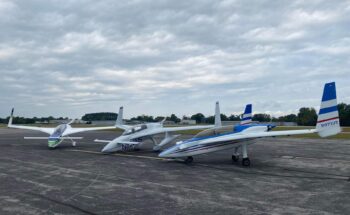
We took the opportunity to position all the birds for a group photo… first with just the Long-EZ’s…
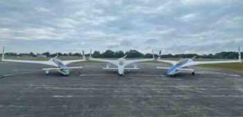
Then with the pilot/owners: Chris, Mike and Marco.
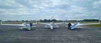
Here’s one more shot from an angle.
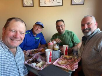
With some time to kill to let the weather clear up a bit (it was all moving East), we grabbed the airport courtesy car and made our way to a local BBQ joint for lunch.
The weather looked pretty good once we arrived back to the London, KY airport from lunch.  Although our new flight plan had us traveling much further south via Knoxville, TN to Asheville, NC, up through Greensboro, NC back to Chesapeake.

Here’s me and Marco in JT taxiing out to the end of the runway to launch.
Mike’s weather heading to Georgia was quite a bit iffier, so he made the call to stay the night and head out in the morning. Here’s his bird all wrapped up for the night.
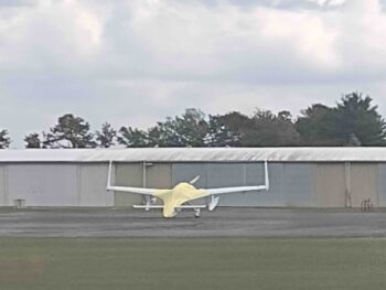
Once in the air, our path south looping around all the weather wasn’t as strictly required as we initially thought.  The cloud coverage wasn’t nearly as heavy as we anticipated so we were able to fly a good bit north of our tracks… saving a decent bit of time and distance.

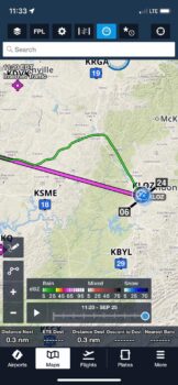
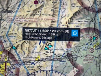
Here’s a screenshot Mike Beasley sent me of our track on FlightAware after we just passed north of Asheville (lower left). We had a tremendous tailwind heading east that kept us pretty fast all the way back to Chesapeake.  Note our altitude at about 11,500′ which we needed to stay above the clouds and mountains.
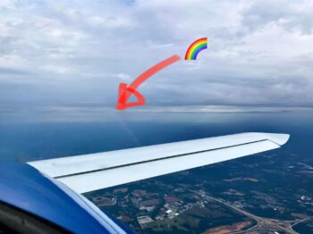
As we were nearing Greensboro, NC we saw a very distinct rainbow off our right side. Marco grabbed this shot, although the camera didn’t pick it up nearly as well as we could see it.
We skirted above Greensboro’s Piedmont Triad International Airport (KGSO) just to the south, which is visible just under the left canard tip.
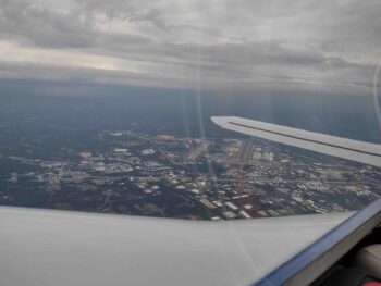
Not too much later we were coming into Chesapeake Airport… another successful Rough River in the books!  A great time looking at airplanes and visiting all our canardian friends.
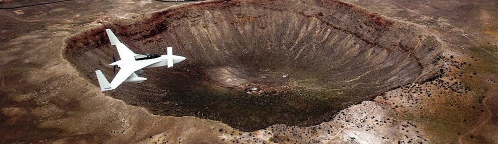
I really do plan on having my bird in the air by next Rough River, so this may be one of the last times flying back seat in my best bud’s awesome Long-EZ… thanks for the adventures and memories Brother!
Chapter 21/24 – GIB strake windows

Starting off, I grabbed one more shot of the O2 bottle mounting sleeve to show the tabs attached to the sleeve.

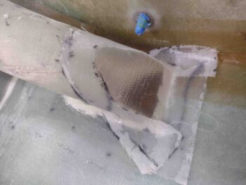
After some sanding, cleanup and prepping of the Clickbond threads with black electrical tape, I then whipped up some MGS 335 with fast hardener to first make flox to add a small fillet around the edge of the Clickbonds, then wet out the 2-ply BID patches to secure the Clickbonds to the fuselage sidewall.  I then peel plied the BID patches.

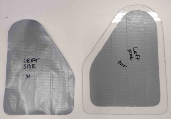
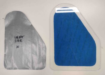
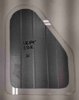
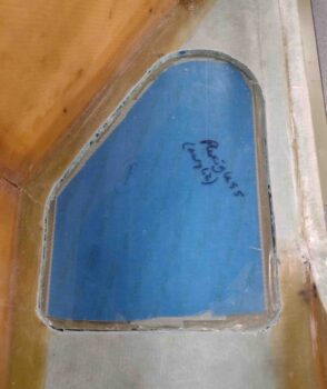
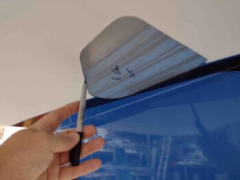
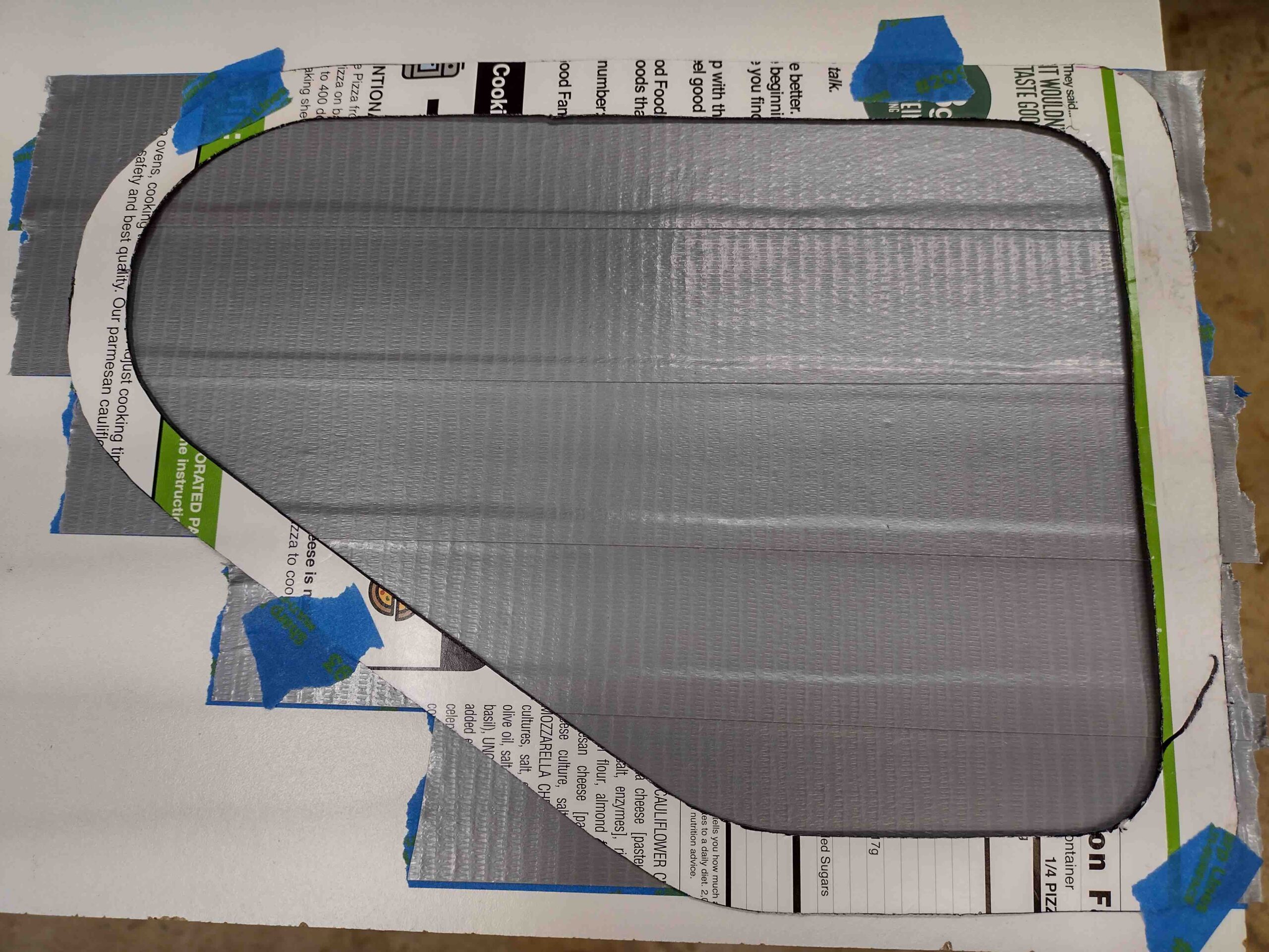
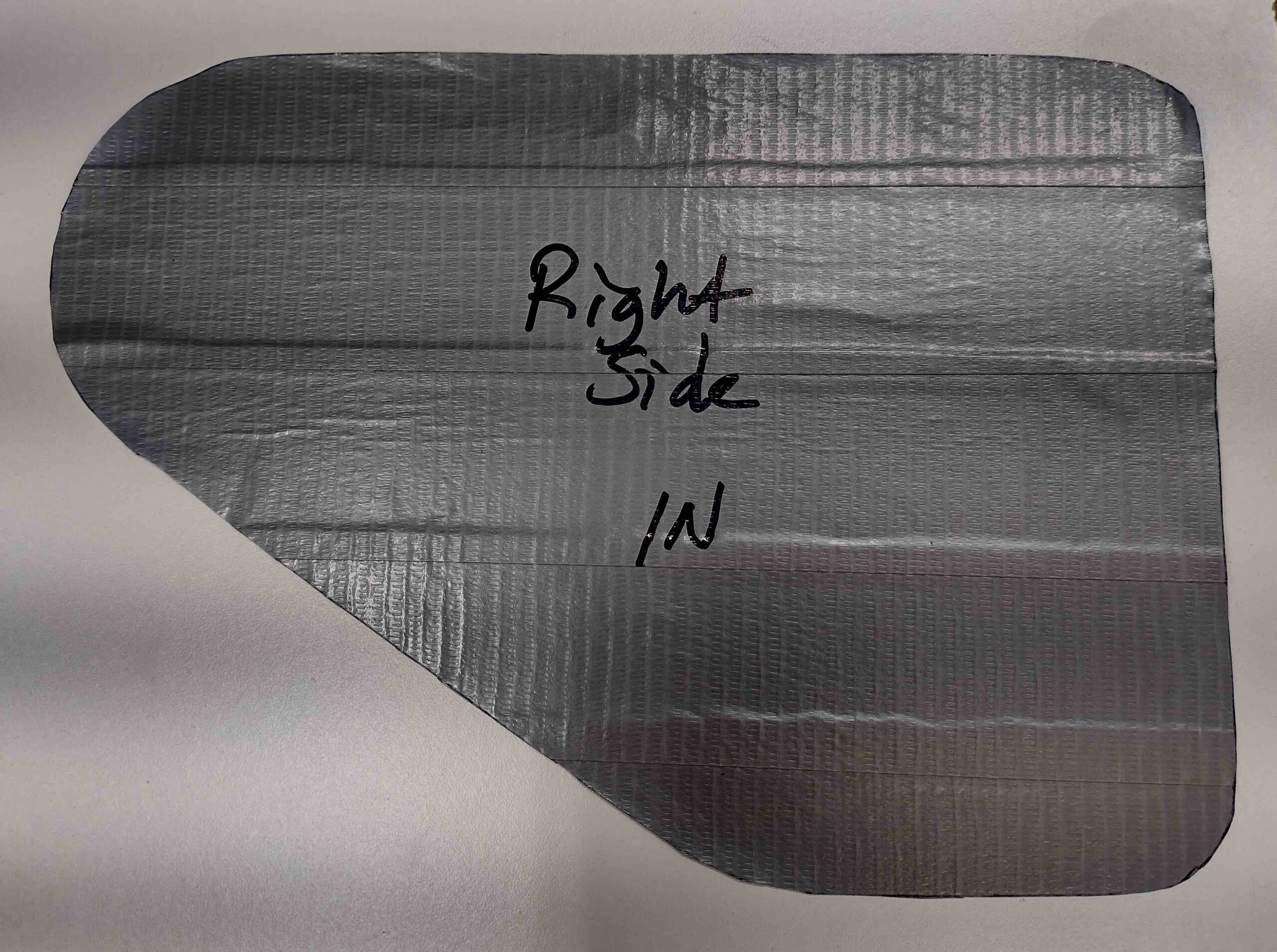
I then marked and trimmed (see right window pane below) the left side GIB strake window pane.  Pressing forward, I used my template to mark and cut out a 2-ply tape protective cover —blue painters tape first, then grey duct tape.  Here it is ready to be applied to the inside surface of the strake window pane.

And here it is applied to the inside surface.

I then applied the same 2 plies to the outside of the right strake window pane.  Note that it’s not trimmed yet.

I then set the right strake window in place… note the blue tape.

I then marked the perimeter of the strake window frame with a Sharpie.

I then used a sharp razor blade to cut along the marked line to remove the perimeter edge tape.

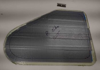
As above on the left side, I laid the 2 plies of tape down on a white board and used the template to mark the inside protective tape sheet.  I then used scissors to cut the along the line.

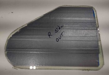
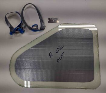
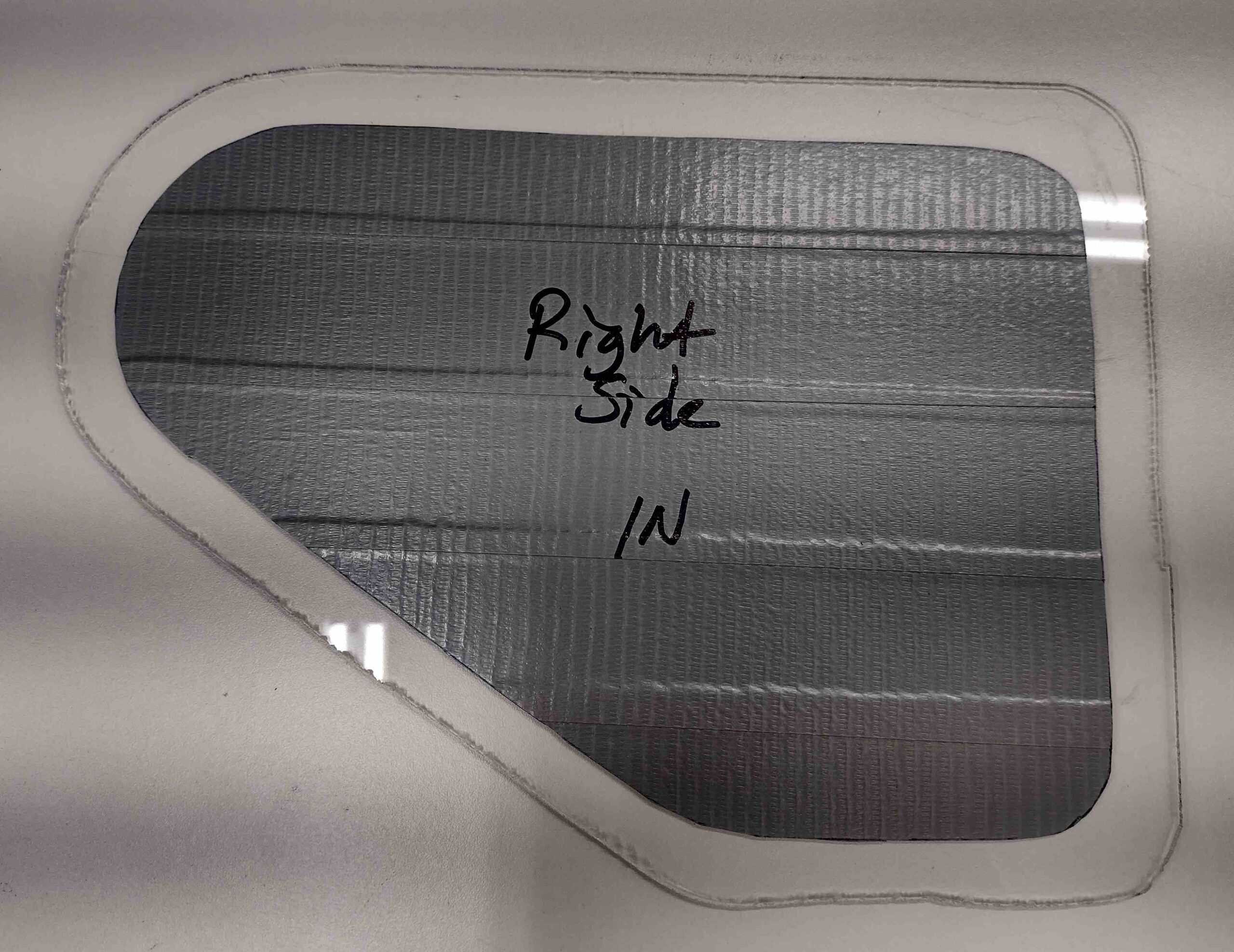
Here we have the right strake window pane with both sides taped up.

A few hours later I removed the protective electrical tape off the threads and the peel plied from the Clickbonds.

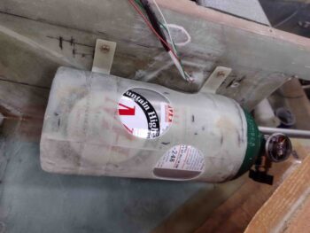
I then temporarily remounted O2 bottle mounting sleeve and grabbed a shot of it from the front seat into the strake baggage area.

This will be the last post until next week, since tomorrow I’ll be heading out to Rough River with my buddy Marco.


Chapter 21/24 – More strake prereqs

Today first thing I started off by adding a single ply of BID over the “backside” of the O2 bottle sleeve mounting tabs where they attach to the sleeve.  There’s a decent amount of glass holding the ‘front’ face of the tabs to the sleeve, but I wanted one bit more on the “back” to help secure these tabs in place.  The bottle is decent size & weight, and especially with any G forces applied during flight I just want to have a little bit extra insurance that it will stay right in place.

I added dry micro fillets/transitions at the edge of the tabs where they met the sleeve body, and then I peel plied just the face of the tab where it would rest against the sidewall of the plane.

While the O2 bottle sleeve mounting tab layups cured, I then got busy cutting out the interior perimeter edge of the left strake GIB window.  Here’s the requisite BEFORE shot:

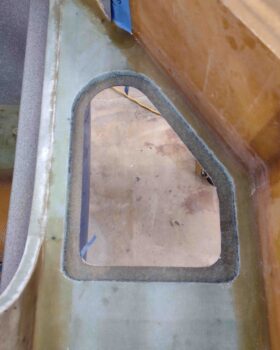
I then taped my GIB strake window template in place, marked the cut line, cut the line, and then removed the foam and glass…

I then took a few minutes to give the freshly exposed left GIB window perimeter glass edge a good cleaning off… removing the dead foam and scraping off epoxy residue.

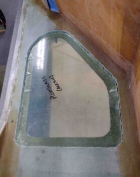
I then test-fitted the 1/8″ thick plexiglass pane into its spot… fit like a glove!

By this point, the MGS 335 resin with fast hardener was nearly fully cured.  I pulled the peel ply and cleaned up the layups on the “backside” of the O2 bottle sleeve mounting tabs.  Not shown is then I marked and drilled a 3/16″+ hole in each of the tabs to allow for AN3 bolts on the top tabs going into embedded RivNuts, and ClickBonds on the bottom tabs.

I prepped the respective RivNuts (top) and Clickbonds (bottom).  I then determined and set the final position of the O2 bottle sleeve mount to allow me to drill the top holes for the embedded RivNuts.

I then whipped up some as-wet-as-possible flox using MGS 335 with fast hardener, and set the O2 bottle sleeve mount in place with both the 2x RivNuts secured in the top tabs and the 2x ClickBonds secured in the bottom tabs.

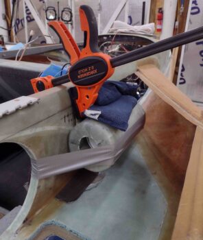
Because of the very slight curve of the fuselage I had to clamp the only top tab I could get to, the aft one, to fully seat the RivNut as far as possible into the embed hole.  This caused the bottom tabs to pop outboard away from the fuselage side, so I had to weigh down the entire O2 bottle sleeve.  I also needed a bit of duct tape to help press in the top forward RivNut as well.  But in the end, my Frankenstein securing method worked!

After nearly 4 hours I pulled the clamp and impromptu weights off the O2 bottle sleeve and removed it.  The flox that had invariably oozed out around the RivNuts and ClickBonds was just barely pliable enough to allow me to remove it with a razor blade and some elbow grease.

Here we have the result: the top two hard points, the RivNuts, are ready to go after another good 12 hours of cure.  On the bottom I’ll add 2-3 plies of BID over the ClickBonds to secure those in place.

I then set the O2 bottle mounting sleeve back in place to double check my fit. I’m really happy with how this is turning out so far.

Because of the angle and tolerance, I’ll need to run the drill through the bottom holes in the mounting tabs to make them just a hair bigger to allow them to slide over the ClickBonds without imposing any side or twisting forces on them.

I’ll clean up the lightening hole on the aft end of the O2 bottle mounting sleeve to make it symmetrical and nicer looking, as well as add some lightening holes in the center area of the sleeve as well.

Chapter 21/24 – Strake Prereq Stuff

This first task I knocked out the first night back from Reno, with a 1-ply BID layup on each seam inside the O2 bottle sleeve mount.  I then peel plied the layups and left them overnight to cure.

Here, a couple days later, I started on the GIB direct fresh air NACA scoop by further deciding how I was going to tackle this beast… with a bit more refined plan.  I’m going to use a direct aluminum tube glassed at each end: one side here at the NACA scoop, and the other at the eyeball vent mount.  With the angle of the tube, I reduced down the interior slope area of the NACA scoop… denoted below with the new cut line.

Which I then cut just the glass away, then shaped the underlying foam.  I also gave the interior bottom glass of the scoop a good sanding as well.  I then laid in dry micro and peel plied it to help shape it.  Once cured, I’ll sand to final shape and contour.

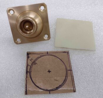
I then got busy designing the GIB direct fresh air eyeball vent mount, using cardboard as a template to then cut out the eyeball vent mount out of G10 phenolic.

I also determined the required length and width of the O2 bottle sleeve mount attaching tabs.

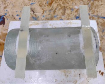
I then 5-minute glued the O2 bottle sleeve mounting tabs to the sleeve tube.

Here’s a closer look.

I had already laid up 2-plies of BID on each side of the GIB eyeball vent mount G10, with an extra couple of plies on the inboard edge of the G10, where I had just over an inch of extra glass to make up the curved attach point onto the aft edge of the GIB strake baggage area opening.  This will give that 1″ x 2″ tab 6 plies of BID so it will be nice and strong.  I also peel plied both sides.

I used fast hardener and once the layup was well on its way to being cured, but still pliable, I taped it into place on the curved attach point at the aft edge of the GIB right strake baggage area opening.

Here’s a shot from the GIB seat to give a general idea of how it will look once it’s installed.

I then got to work on creating micro fillets between the freshly attached O2 bottle sleeve mounting tabs and the sleeve tube itself.  I then laid up 1 ply of UNI that covered from the end of the top tab, around the sleeve tube, to the end of the bottom tab.  I then added another ply of UNI that covered the tab and overlapped onto the sleeve tube about an inch.  Then a final ply of BID that covers the mounting tab and overlapped onto the sleeve tube also about an inch.  I then peel plied the layups and left them to cure.

Here’s a shot of the bottom side of the O2 bottle sleeve mounting tab layups.

A bit after I finished the O2 bottle sleeve mounting tab layups, the GIB eyeball vent mount layup was cured, so I pulled the top layer of peel ply and marked the inside mounting tab edge for trimming.

I then took the GIB eyeball vent mount off the sidewall opening edge, pulled the peel ply, razor trimmed and sanded the edges, and trimmed the interior edge of the mounting tab before taping it back in place for a test fit.

Here’s a shot of the GIB eyeball vent mount from the back side (technically front) as it’s taped in place for test fit.  It’s looking good so far!
And with that, I called it a night.