Chapter 9/25 – Wheels & paint

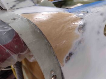
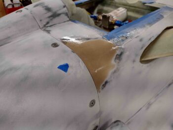
I started out today by sanding down and blending the West 410 mixture fill on the bottom right side of the bottom cowling’s front edge.
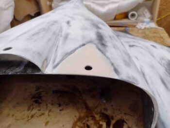
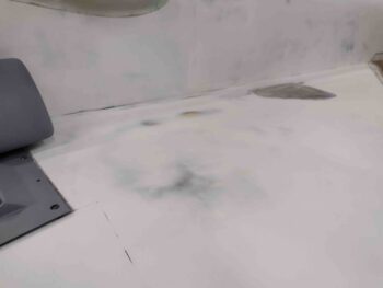
To ensure the level was correct —which is the whole purpose of this effort— I remounted the cowling onto the taped aft fuselage to then sand down the filler level with its mated fuselage.
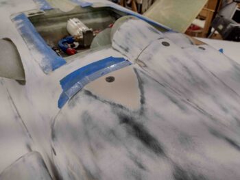
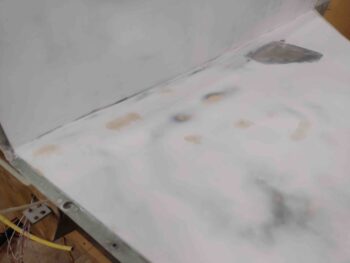
Although not the greatest pic, this shot gives you an idea of how blended this patch job is.
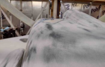
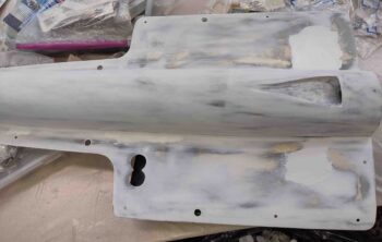
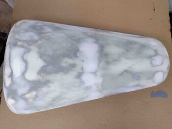
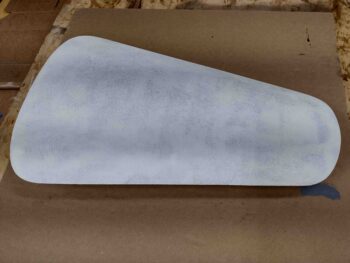
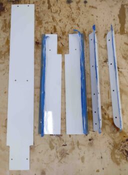
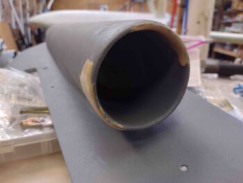
I then grabbed the nose gear fairing and gear doors and took them outside to sand them down. I first hit the exterior surfaces to clean those up and prep them for paint.
Since I still have some dust specs throughout my white paint, I wet sanded the inside white surfaces down in prep for buffing and polishing.
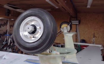
Back inside the shop, I then took a bit of time to clean up the wheel and tire assemblies. First cleaning the inboard side of the wheels, then the outboard.
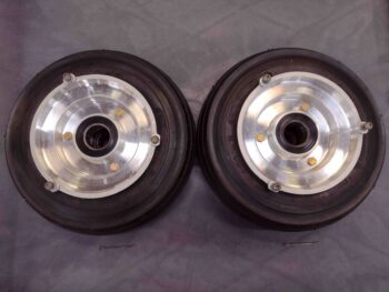
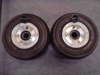
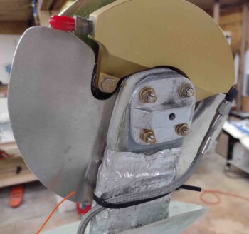
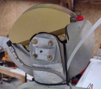
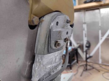
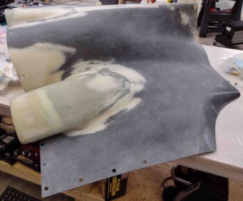
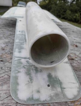
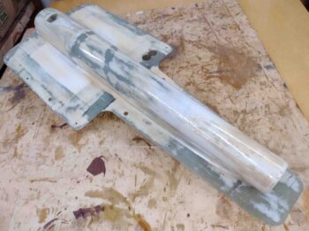
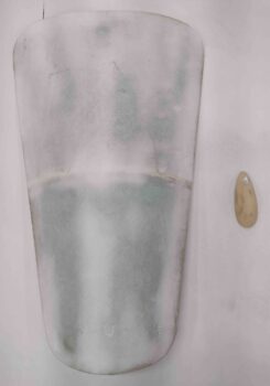
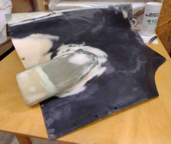
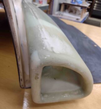
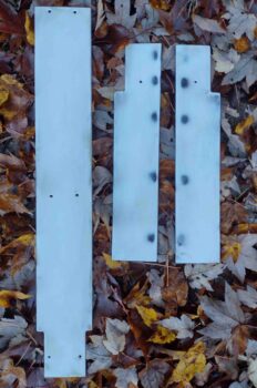
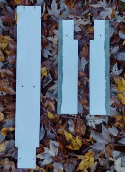
I also finally removed the labels from the outboard wheel pant mounting adapters and cleaned them up (see 2 pics below).
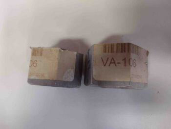
Then, per the Matco manual, I rechecked all the torque specs on the brake bolts.  Out of 12 bolts I had only one that needed just a minor tweak.
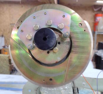
I then remounted the wheels/tires onto the axels, for good this time.  Cotter pins went in into the axle nut and were bent back to ensure they stay secure.
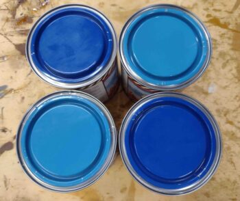
I then spent well over the next hour mixing 2 cans of light blue paint with 2 cans of darker blue paint, and then all together, to give me the medium blue paint I was looking for.
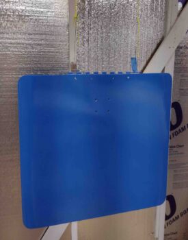
I then went to work painting the various components of the bottom of the airplane.  First up was the landing brake, which I suspended in mid-air to allow painting both the exterior side and the interior edges around my checkerboard artwork.
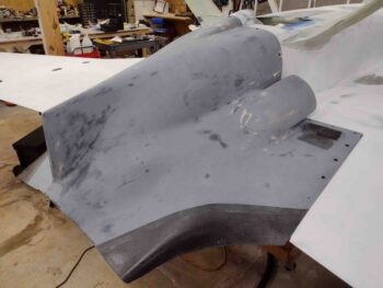
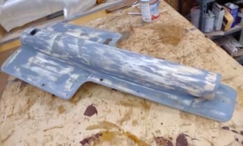
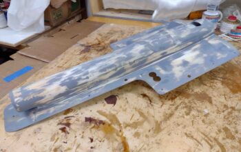
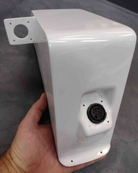
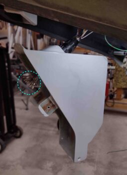
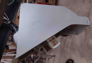
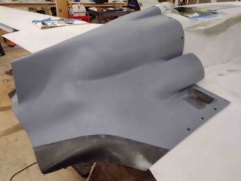
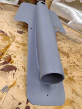
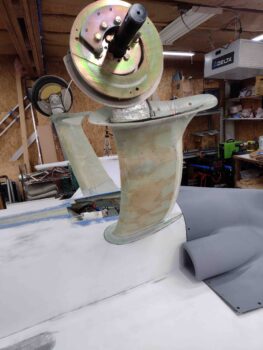
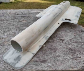
I then painted the nose gear accessories, the belly video camera mount, and the RAM air scoop/hell hole hatch cover.
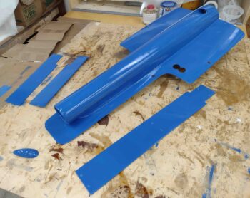
Here’s another shot of all those from a different angle.
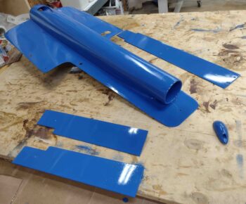
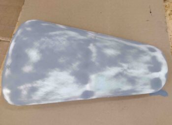
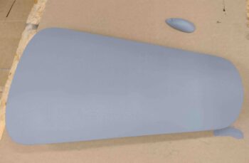
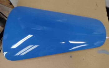
Included with the bottom-of-plane components was the top nose hatch door.  It came out fairly nice.  Note that all these items will get sanded in between coats, and will most likely have to be color sanded, buffed and polished to achieve the final shine.  Not what I wanted to have to do, but that does give me a highly durable/maintainable and great looking paint job for well under a grand.

I’ll also note that I discovered that the 220 grit scratches are showing through on at least the first coat of the paint.  We’ll see how it looks once sanded and recoated, but this is once again why I wanted to do all the bottom components (this hatch door being the exception) before tackling the much more visible top side of the plane.

And to be clear: from here on out my final pre-paint sanding will be with 320 grit.
Another issue that I ran into… specifically during this paint session, was that the first batch I made was woefully not enough and I only got the landing brake completed.  However, I way overestimated how much I needed for the second batch of blue paint that I whipped up and was left with a real good bit after painting everything I had prepped (all previous pics)…. now, this paint job is a whole lot cheaper than paying someone to do it, but it is NOT cheap paint.  Thus, I don’t want to waste a drop if I can finagle it.

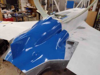
Well, the only other viable candidate to be painted was the bottom cowling… which was NOT on the list to be painted tonight.  So I quickly taped off roughly what I estimated the borders to be, then cleaned it quickly before slathering on a good bit of blue paint [Note the re-installed tires/wheels].
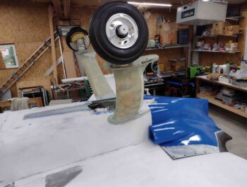
Normally I use the word “slather” half in jest, but unfortunately I did lay it on a bit thick here to create a nice thick base coat.  Clearly the vast majority of the bottom cowl is like a steep ski slope and I had a fair number of runs.
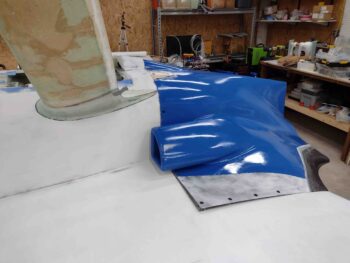
Still, I’ll reiterate that this type of experience is what I’m trying to dial in to get a good feel for this paint system.  Yes, the bottom cowling is a fairly visible component, but this being the first coat gives me a good idea of how thick I should be laying down the paint.
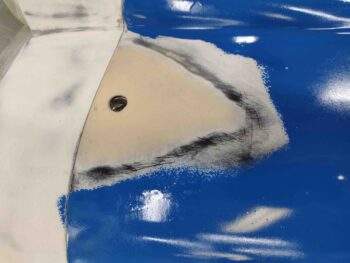
I’ll also note the West 410 mixture fill, that I sanded down earlier, was epoxy wiped with 3 coats of West epoxy and is ready to be sanded and primed.
And with that, I called it a night on this very long build day!
 

Chapter 25 – Still paint prepping!
Today I started off by finalizing an Aircraft Spruce order mainly for some odd and end hardware stuff, including CAMLOCs, NORD lock washers, and restock of miscellaneous screws and bolts.  I also ordered the correct <ahem!> rivets (BSC-44) for mounting the rudder hinges to the rudders.

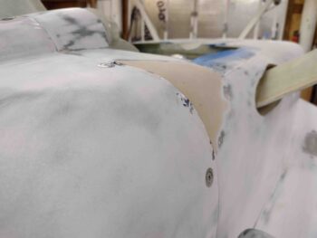
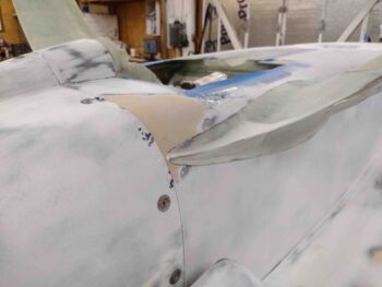
I then got to work on sanding and contouring the cured West 410 filler I applied to the lower aft left fuselage “corner” to level out the surfaces betwixt the fuselage and bottom cowling.

I was pleased with the shape and transition, but I had to then check one more thing: the interface between this fresh West 410 fill and the left gear fairing.  The impact was very minimal so I pressed onward.

I then whipped up a bit of West epoxy and applied it to the surface of the West 410 fill and the immediate adjacent fuselage surface.  This was epoxy wipe #1 of 3.

This is much later after I applied epoxy wipe #3, with it nearly cured to the touch.

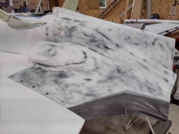
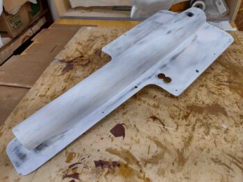
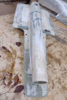
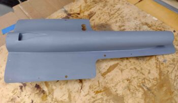
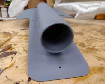
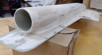
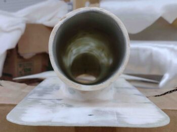
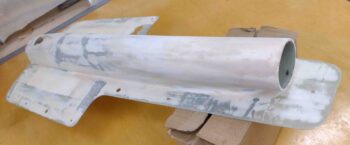
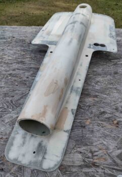
I then finalized my sanding on the RAM air scoop/hell hole hatch cover before then applying yet another round of thickened white primer… primarily to the 2 areas on the aft side where I had slight depressions.  I also touched up a couple spots along the right flange (bottom of pic) near the corner where it intersects the scoop structure.

Finally, I used some of the thickened white primer to add just a dollop at the the aft center where I had a remaining low/rough spot.  I’m fairly positive that this latest round of white primer should clean up the blemishes on the surfaces of these parts to get them ready for paint.

And with that, I called it a night.

Chapter 9/25 – Edging towards paint!

This post actually covers the last few days.  Later in the evening Monday night after I finished up sanding down the gray primer and applying the white primer my back was really out of whack.  I believe it was from the sanding on a table outside that was just a bit low for me, and so the constant slightly bent over position got me.

I took it easy Tuesday and worked on important admin stuff by adding the new J12 Molex connector to the list of connectors document I have for the plane.  I also updated the associated info on the P1 connector and header page that identifies every connector in the plane.  In addition, I updated the Nose Gear wiring diagram to include the new J12 Molex connector.  Finally, I did do some organizing on a bunch of my loose documents that I still haven’t completely recompiled after the tornado hit my hangar and drenched my binders full of notes and pertinent build docs.

Yesterday I finely sanded the aft inboard area of the bottom left strake.  This has been a problem area for me for some reason in how the finish came out.  After another application of thickened white primer, and this latest sanding, I finally got the surface fairly contoured (aka flat) with only a few rough areas and divots.  I decided to go with West 410 to refill these problem areas and then hit it again with white primer to hopefully, finally knock out these surface blemishes.

In addition, I knocked out some required ancillary tasks like flipping the engine back upright and reloading all the larger orifices (exhaust ports, cold air induction plenum) with fresh desiccant packets before installing fresh desiccant cylinder plugs and firing back up the engine dehydrator system.  I also added another quart of oil as well.

Finally, besides a good bit of research on Matco wheels and brakes, as well as my Epifanes paint system, I pulled all the blue tape strips off the plastic protecting my canopy and moved them to different spots to ensure I don’t get any egregious “old tape” spots on my canopy.

Today I finally got back to work!  I did make a couple calls to confirm some info with both Matco on my brakes and with Epifanes to dial in my paint application process.  I will also note that I dialed in and determined my FINAL paint scheme for the bottom of the plane.

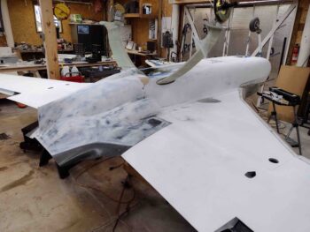
In the shop I started by sanding down the white primer on the bottom cowling, removing a good bit of it in the process. I then installed the bottom cowling onto the plane.

In addition to thickened white primer touchups I did on all these parts I just sanded (see below), that pesky front edge of the cowling at the lower left “corner” of the fuselage reared its ugly head again. The bottom line is that the front edge of the cowling sits around 0.080″ above the mating surface of the left aft bottom corner of the fuselage.  I simply couldn’t ignore this any longer and had to fill in that corner with West 410 (just aft of the gear leg).  And yes, I have worked this exact area before… so I’m trying to keep my frustration at bay and simply work the issue.

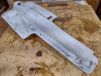
I also sanded down the white primer on the RAM air scoop/hell hole hatch cover. I then applied more thickened white primer to areas towards the aft end of the hell hole hatch cover.

I then did the same thing on the nose hatch cover, sanding down the white primer and then reapplying thickened white primer in the slightly depressed areas.

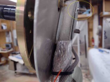
I then finished the main gear axle bolt swap outs by pulling all the AN4-21A bolts and replacing them with slightly longer AN4-22As. Again, years ago when I installed the wheel pants’ inboard brackets it resulted in the axle bolts being too short since the flanges on the wheel pant mounting brackets are about 1/8″ thick.  At the time the fuselage was upright and on the main gears/wheels so I didn’t mess with pulling the wheels/tires to gain access to the axle bolts.

In this pic you can see the difference between the length of an AN4-22A bolt (at top, circled) and the shorter AN4-21A bolts.

Clearly with the bird inverted it is an opportune time to knock out this axle bolt swap out.

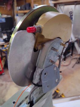
Unfortunately, as I was tapping in one of the new bolts it knocked off the inboard axle bolt securing plate. Not a huge issue of course, it just added another 15 minutes of work.  I first cleaned up the interface between the plate and the gear leg.

And then mixed up some flox and reattached the plate when I re-installed the cleaned up inboard wheel pant mount.  Note that on both gear legs the axles are now permanently installed with no-kidding aircraft grade washers and nuts.  Also note that I cleaned up all the wheel and brake parts during this bolt swap/install.

By the time I finished the bolt swap out it was getting late, so I called it a night. I do plan on double-checking all the torque specs for the Matco brake hardware before remounting the wheels for the final time.  And of course continuing on in my quest to get the bottom of this bird painted!

Chapter 25 – More white primer

I started off today by spending a couple of hours wet sanding the bottom cowling’s gray primer surface with 220 grit sandpaper.

It takes a bit of extra time sanding this bottom cowling since you have to get in and around the armpit air intake scoops.

As I’ve mentioned before, I use the gray primer first because it pretty much acts as a de facto guide coat for sanding.  I do sand it fairly vigorously since I consider the white primer as the “real” primer surface.  The gray primer is an intermediate step to help dial in and finalize surface contour smoothness to eliminate any irregularities before the paint goes on.

I then did the same thing on the RAM air scoop/hell hole hatch cover.  Clearly this took way less time.  Not surprisingly, you can tell when lightly running your hands across the surface how much more smooth and dialed in the surface contour feels than prior to the primer being applied.

Finally, I wet sanded the gray primer on the nose hatch cover as well.  I know I’ve stated it many times, but I’m not looking for a perfect finish… just a really nice one!

After a good half hour prep, and then mixing up a batch of white thickened (with micro) primer, I then spent well over the next hour applying it to the bottom cowling, RAM air scoop/hell hole hatch cover and nose hatch door.

I left the freshly white primered components alone for a good hour, at which point they were dry to the touch.  I then placed them gently back onto the airplane.

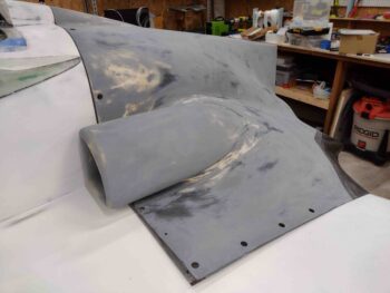
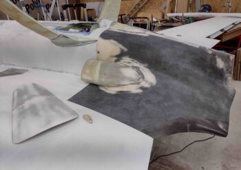
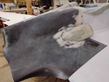
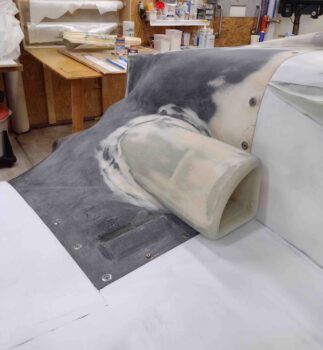
Here we have the RAM air scoop and armpit air intake showing now in white primer.

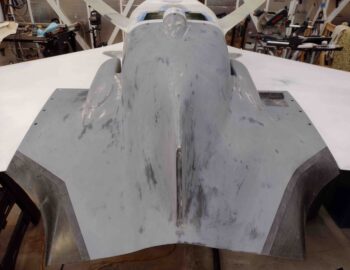
The white primer doesn’t mask dark surfaces completely in only one coat, and I didn’t mix up enough to cover everything with 2 coats.  This is not a problem though since the lower area of the cowling (upper in these pics) from the armpit scoops “up” are what will be getting painted this go around.

I can always apply another coat of straight white primer if need be before the white paint goes on the outboard horizontal surfaces of the cowling. Moreover, I clearly will be doing a bunch more finish work in these areas when I integrate the mounting of the top cowling with the bottom cowling.

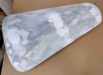
Here we have the nose hatch door in white primer.  I’m very satisfied with how the white primer laid down and cured on these parts.

Now to start prepping for some paint!

Chapter 25 – Paint & pinholes

Today wasn’t a big work day on the build since I had my little buddy with me a good portion of the day.

I was able to wet sand the surfaces of the white nose gear components with 350 grit sandpaper before prepping and then applying another coat of white paint.  This time I used a bit more paint and what was supposed to be a higher quality foam roller, but I still ended up with a myriad of little air bubbles on the paint.  Note that while a majority of boat paints need tipping with a brush, this system supposedly doesn’t require that.

The finish on these parts is not super critical since they are not located in an overly hi-vis area, so it does allow me to dial in the paint application process while I concurrently knock the painting of this stuff out.  I may need to do some wet sanding and buffing out for these guys, but clearly would like to avoid that on the entire plane’s painted surfaces.

I’ll do some research and make some calls.

I understand these aren’t the greatest pics below…  I actually had my little 12 yo buddy help me mix up some West 410 and fill the numerous pinholes on the bottom cowling.  I originally figured I had spotted about 12 of them, but the final number was well over 20.

I then used the remaining bit of West 410 that was in the cup to add a little thickness to the outside of the RAM air scoop opening on one side, and then fill in a bit more on the inside of the lip about 180º out from the first fill.  I’ll continue my iterative process of filling and dialing in the shape of the RAM air scoop opening to ensure it has “a pleasing shape.”

Tomorrow I plan on sanding down all the gray primered components and applying a coat of white primer to them.

Chapter 22/25 – Electrons & Primer

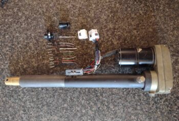
This morning I finished up a project that I’ve been working on over the last few evenings to insert a Molex connector into the wiring bundle between the nose gear actuator assembly and the P1 CPC connector.  The main wires that run through the P1 connector are the gear actuator motor power wires, the up/down limit switches wires and a slew of signal wires for the gear up/down/transit indicator and warning lights.

The issue was the interface between the P1 connector and the NG30 cover.  In the quest for easy maintainability and access, the question regarding the P1 connector was how to mount it to the inside of the NG30 cover that would then allow for it to be disconnected in an efficient manner when the NG30 cover was removed.

If there were a reliable way to mount nutplates to the corners of the plastic bulkhead flange on the P1 connector, that may have been a potential solution… albeit not the most elegant or reliable one over the long run.  That solution would require having to remove 4 extra screws every time I wanted to remove the NG30 cover.  Moreover, the ability to mount nutplates to the bulkhead flange with the space provided was problematic.

Although I don’t like adding connections into electrical circuits, after literally years of pondering the solution to this issue I decided to proceed with adding a 12-position Molex connector into the wire bundle between the P1 connector and the nose gear actuator motor and limit switches.  This would allow me to separate the NG30 cover from the NG30 by simply disconnecting the Molex connector in a couple seconds (vs a minute+ of removing screws).

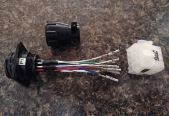
Time has a way of masking problems, and one potential issue I had to check was the fit of the P1 connector into the currently painted NG30 cover.  Thus I had to clean the paint out of the P1 connector mounting hole on the NG30 cover since I haven’t had the two halves of the P1 connector together through the NG30 cover connector mounting hole since after it was painted. Clearly I definitely wanted to ensure that there was still enough clearance for that to work… as you can see here, there is just enough.  It’s tight, but the halves do connect [note the terminated ends of the wires circled in light blue].

I turned the above pic sideways to show how the external side of the P1 connector will look when the NG30 cover is installed in the nose of the plane.

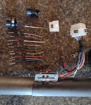
Going back in time a few days, this is how this task evolved.  First I cut the bundle of wires close to the original P1 connector, leaving about an inch of wire hanging off the CPC sockets.  After mapping out the wiring on paper, I then terminated the motor side wire bundle with Molex pins and mounted them inside one half of the Molex connector.

I then had a decision to make: cut and terminate both CPC and Molex sockets onto fresh wires? Or add lengths of wire to the existing 11 CPC sockets and then terminate the opposite ends with Molex sockets?  I chose the latter.

Since I didn’t want to waste any CPC sockets (the power wire sockets are gold plated) I went ahead and simply found the same color wiring in my spare wire bag and soldered these lengths to the existing CPC sockets.  I then added heat shrink to protect the solder splices.

Once the wire lengthening process was complete, I then stripped and crimped Molex sockets onto the ends of the newly added lengths of wire.

I then wrapped the wire bundles in tape, secured them with a zip tie and terminated the sockets into their respective connectors (after performing continuity checks on my work).

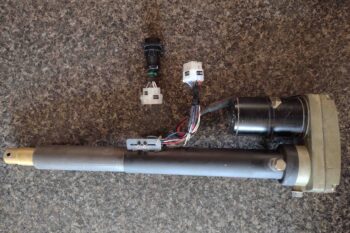
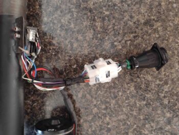
Voila! Here we have the new J12 Molex connector in place on the nose gear actuator.

And a closer look at it…. all nice and clearly labeled!

I then went out to the shop and spent a good 45 minutes in final prep on the bottom cowling to allow me to apply thickened (with micro) gray primer.

Although I could see about a dozen pin holes on the surface after about an hour into the cure of the primer, I’m extremely pleased with the surface contour and smoothness of the cowling.

With the same batch of thickened gray primer I also applied it to both the nose hatch door and the belly video camera mount.

I had planned on applying primer to the RAM air scoop as well, but I knew it would take a while to get it sanded to the final point of being ready for primer… and may have quite possibly needed some refills in areas with West 410.  Thus, I did my first round of primer above, and then got to work sanding the RAM air scoop/hell hole hatch cover for another good hour+.   Thankfully I wouldn’t need any more filler on the RAM air scoop and immediately rolled into cleaning and prepping it for primer.

As you can see it turned out very nice.

Again, I’m very happy with how the thickened gray primer laid down on the RAM air scoop/hell hole hatch cover.

I know I’ll be tweaking the RAM air scoop opening to dial it into as much of an evenly thick, concentric circle as possible… but it’s already looking pretty darn good IMO!

There were actually a couple of tasks I knocked out pre-primer but didn’t get pics of until a bit later.

First, I used 220 grit sandpaper to wet sand the thickened white primer I applied to the aft inboard area of the left strake to help clean up some surface irregularities there.  It really came out nicely, although I still have 2-3 minor spots that will need filling before final primer and then paint.

I also removed the right wheel assembly to expose the axle bolts and then allow me to remove one of them to check its length (yeah, I didn’t have the length annotated anywhere…).

Making and installing the inboard brackets to secure the wheel pants not surprisingly caused the axle bolts to be just a hair short.  Turns out that the bolts I had installed were AN4-21As, not the AN4-22As called out for in the plans.  Just another example that if I had followed Burt’s guidance I wouldn’t need to swamp these things out now… ha!

Regardless, I do need to clean up the wheel assemblies and ensure the bearings are nicely packed with grease, so this endeavor shouldn’t be an overly difficult or time-consuming one in addition to my other wheel beatifying duties.

Tomorrow will be a short build day, but I do at least plan to get those pesky pin holes filled!

Chapter 25 – Preppin’ for Primer!

Today I started off by prepping the nose gear strut fairing, the nose gear doors and the nose gear door hinges for white paint.

I then mixed up the white paint and applied it to these nose gear accessories.  I used a foam roller and was a little bit light on the paint, so I believe I induced some air bubbles into the paint surface.  Thus, I’ll wet sand and apply another coat after it cures.

I also painted the outer edges of the aileron pockets —which are already in white primer— since these areas are visible when the ailerons are deflected up and down.

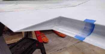
Here’s the inboard side of the aileron pocket.

And the outboard side.  I did this on both wings.

I then spent well over an hour finalizing the sanding of the bottom cowling.  I cleaned up the edges and also redrilled the CAMLOC mounting holes.  I then remounted the bottom cowling onto the plane to double check its fit.

I also knocked out the final sanding in prep for primer on the top nose hatch door and belly video camera mount.

The epoxy wipes of course added just a hair bit of thickness on the front edge of the cowling, so I had to address this and sand down all the edges to ensure the cowling still fit well.

The cowling is a tight fit on the fuselage… nothing egregious or crazy, but I would guess it sits about 0.015″ aft of its original alignment.  It just makes the CAMLOCs fit a little tighter. I would also guess this may loosen up just a bit over time as well.

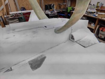
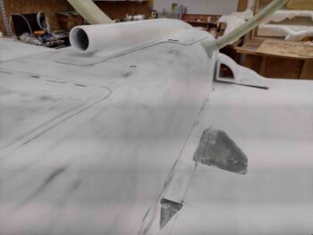
Here’s a shot of the left armpit air scoop, the gear fairing and the cowling intersection with strake and wing.  I’m happy with all these and so far, so good!

A shot of the the same on the right side.

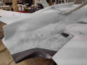
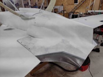
Here we have a side shot of the re-installed bottom cowling.

After I took these pics, I did do some very minor West 410 refills in a few spots on the bottom cowling.

I also worked a bit more on the shop cleanup/organizing and some electrical work that I’ll report on in tomorrow’s blog post.


Chapter 25 – Why, I love sanding!!

My first task of the day was to knock out the final major sanding of the bottom cowling…

And yes, as always there are few minor things to clean up before I lay down some primer on this beast.

I then got to work on the RAM air scoop/hell hole hatch cover and sanded it in prep for epoxy wiping . . .

Which I rolled right into.  I only did 3 total wipes spaced out about 2.5 hours apart, using West 206 (slow) hardener.

I then did the major sanding on the epoxy wiped nose top hatch door and the belly video camera mount.  I sanded these outside in the dark [with lights on, still not great lighting] and realized I got them both to about 90% done.  I’ll work them both again just a bit tomorrow to finish them up in prep for primer.

And with that, I called it a night.


Chapter 25 – Yup, more finishing!

Today I started off by sanding the RAM air scoop/hell hole hatch cover to pretty much final configuration… and ready for epoxy wiping.

I then went off script for a bit to knock out an ancillary task: the aft NACA scoop ground cover attachment.  I’ve been pondering this for a while, and after learning that my local airport’s schedule to have the new replacement hangars built has slipped again to the summer of 2022 (for the hangars, including mine, that were damaged in a spin-off tornado from hurricane Dorian). Thus, if I finish my Long-EZ prior to next summer –which I fully intend to!– I very well may need to keep my bird parked out on the ramp for a period of time.

In light of this hangar situation, I want to ensure all open holes in the plane are plugged or capped to ensure no bugs or critters take up residence in any aircraft orifices.

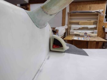
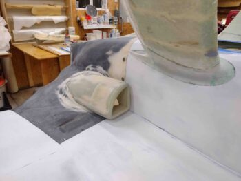
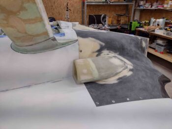
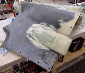
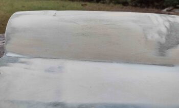
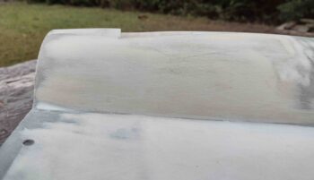
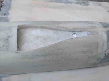
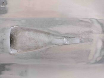
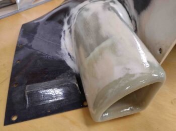
I will say that in addition to sealing up the plane during ground parking on the ramp, there is an element of cleaning up the lines when viewed from the side by eliminating the slight “notch” of the NACA scoop on the rounded aft RAM air scoop structure.  See the top vs bottom pics here.

Again, I’ve been pondering just how to attach this NACA scoop cover for a while now.  I finally decided that I would have a rubber/foam type plug that goes into the hole on the aft side, and then a small embedded magnet to keep the front narrow part of the cover attached to the NACA.

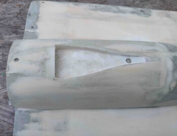
Here we have the mounting hole drilled and prepped for a small round embedded magnet.

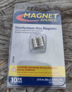
Since I had these magnets on hand to use for my lathe RPM/tach display, I simply grabbed one for use to secure the aft NACA scoop cover.

After I test-fitted the magnet in its mounting divot, I then sanded the surfaces of the magnet to texture it so that the micro could grip it a bit better.

I then micro’d the small magnet into place in the front channel of the NACA scoop.  You can also see that I added some micro to the aft corners and spots inside the NACA scoop.

I then added a pure flox lip to the front edge opening of the RAM air scoop.  I wanted something that would add strength and durability to anything getting thrown at the RAM air scoop in flight, in addition to being able to be shaped to allow me to create a rounded/radiused edge on the front lip of the RAM air scoop.

I then left the the RAM air scoop and NACA to cure while I spent a good hour sanding the bottom cowling (sorry, no pics).  Tomorrow I’ll press forward with getting these ancillary components prepped first for primer, then paint.

Chapter 25 – More component sanding

I started out today sanding and contouring the last round of West 410 application on the RAM air scoop/hell hole hatch cover.

I’ll admit that my RAM scoop isn’t a perfect concentric circle, but it’s pretty darn close and will work fine for what I need it to do.

Again, here’s another shot of the RAM air scoop/hell hole hatch cover near-final sanding.

That being said, I did need to do a few final/minor touchups with another round of West 410.

I then did another round of sanding on the epoxy-wiped bottom cowling, this time focusing primarily on and around the right armpit scoop.

The biggest challenge on sanding down the cured epoxy wipes on the bottom cowling is the channels on the inner and upper sides of the armpit scoops (in the pic here that would be the left and bottom side).  This effort includes sanding both sides of the channel, which would be the surface of the cowling along with the inside face of the armpit scoop.

In hindsight I should have A) only did 2-3 rounds of epoxy wipes max, and B) sanded the cured epoxy wipes sooner, as I have previously mentioned.

Finally, there is the aft “floor/wall” of these channels, which is the original flange that is floxed & glassed to attach the armpit scoops to the cowling surface.  These are obviously a challenge to sand since the only way in there is to wrap sandpaper around some type of stick or pad… patience and persistency being the rule in sanding all of these internal armpit scoop areas.

Since I’m wet sanding, I do most of my sanding outside.  Well, with the days getting shorter and colder it was darker (even with outdoor lights on) for a good bit of my sanding session.  I did a good 1.5 hours before calling it a night, and as you can see in the pic below I was not able to finish the left side.  This shot gives you a good idea of what the cured epoxy wipes look like pre-sanding.

I did do a fair bit more organizing and cleaning in the shop –well over an hour’s worth– so I’m slowly getting there.  Pressing forward!