Chapter 9 – Wheel Pants . . . etc!

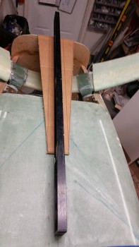
Today I started out by refining my wheel pants prep & wing mounting to CS spar plans.

I then discovered that my UPS friends had delivered my ACS order, and yet another Mouser order. I logged my new parts in my spreadsheet, sorting through the myriad of CAMLOC bits ‘n pieces & more new panel switches.  I identified all the switches, labeled each one, and stowed them away with all the other switches.

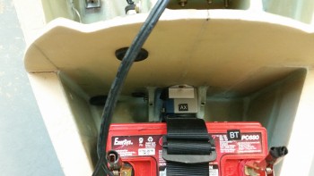
One new item of note that I received today is the TCW Technologies 3-Amp hour Integrated Backup Battery System (IBBS).  After W&B discussions with Marco regarding his new Long-EZ, he had advised me to literally front load as much component weight possible into the nose region of my plane to favorable counter the sensitive rearward balance tendency of Long-EZ’s.

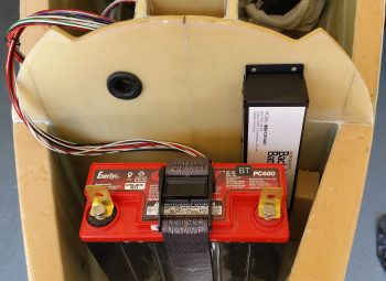
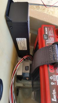
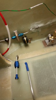
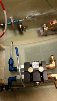
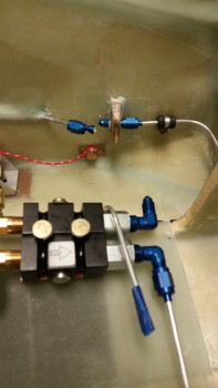
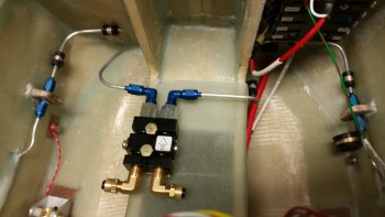
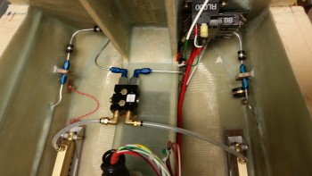
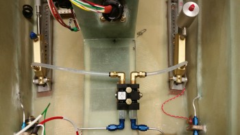
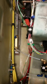
As I mentioned in a previous post, I had originally planned to install a 3AH model IBBS since it would serve me well enough –and for the specific reason that I would be saving weight over the 6AH model.  So upon the “load the front heavy” advice I received from Marco, I assessed putting in the bigger model.  Ah, but alas, the 6AH model was physically too big to mount it where I had planned (see pic below) so I went with my original plan and pulled the trigger on the 3AH IBBS.

Testing IBBS fit

As you can see in these pics, the 3AH IBBS fits perfectly… and according to plan!

Testing IBBS fit

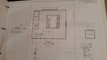
After getting all the first half of the day’s miscellaneous tasks out of the way, I started in on something I’ve been trying to knock out over the past few days.  You see, Marco has been diligently working on the pitot tube wiring system for our Long-EZs, and I haven’t been the best teammate in assisting with the effort (See Marco’s latest post regarding the pitot tube electronics on his blog).  Moreover, a number of days ago Marco asked if I could draft up the wiring diagram (#24) for the Heated Pitot Tube Electronics.  Thus, a main goal I had today was to get this sucker knocked out, which I did below.  Of course there will be a bunch more mods to this diagram as we move forward, but as of right now we have a good baseline schematic for the pitot tube electronics!

Pitot Tube Electrical Diagram

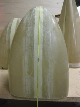
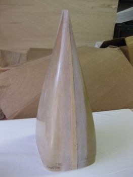
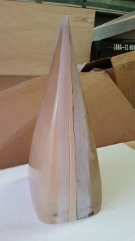
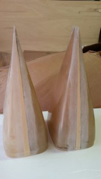
After completing the heated pitot tube wiring diagram, I then went down to the shop to get some work in on the wheel pants.  My current issue is one that many builders seem to be confronted with, but oddly enough I’m starting to see a possible nascent trend that only 400×5 tire users seem to be afflicted by ? . . . and that is that until some type of slots are cut into the bottom of the wheel pants for the tires, the front and back half of the wheel pants can’t be mated together.  Nate Mullins certainly had this issue.

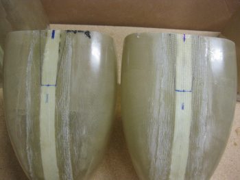
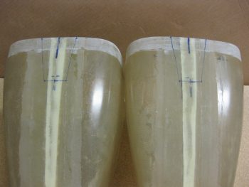
As it goes during many a times during this build it was time to take yet another leap of faith and cut into the bottom of the wheel pants.  Of course I don’t know exactly where the wheel will reside in each wheel pant, which prompted me to look at a myriad of pics from other builders’ installs.  I decided to shoot for center mass: 4″ forward on the front side of the wheel pants and 3.3″ aft from the front edge of the aft side wheel pants.

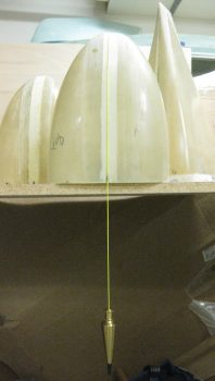
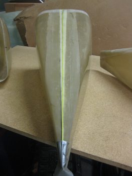
Since I would destroy the bottom CL mark by removing the glass on which it resides, I decided to move the CL marks out of the lines of fire on all the wheel pant parts.  I grabbed my tape and a plumb bob line and ran the line down the CL of the wheel pant… Uh, except maybe I should aim for the correct side of the wheel pant! (I started on the top of the wheel pant in the pic below, but luckily I caught my error!)

Marking top (wrong side!) centerline

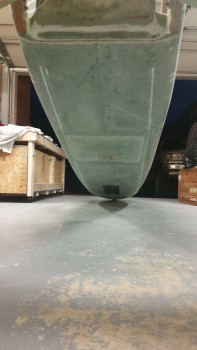
Ok, the BOTTOM of the wheel pants… this is much better!

Marking bottom (right side!) centerline

I then marked the aft edge of the front side of the wheel pants for certain destruction and mayhem!  Hoo-ah!

Bottom front wheel pants marked for cutting

I then extended the centerline mark rearward on the aft wheel pant pieces as well.

Finding aft bottom centerline

And marked out the areas of certain destruction on these as well!

Aft wheel pants marked for cutting

After cutting out the notches in each side of the wheel pants, I still couldn’t get the aft flanges into the front side receivers!  I ended having to extend the notches another 1/2″ forward and aft, respectively, into the wheel pant assemblies.

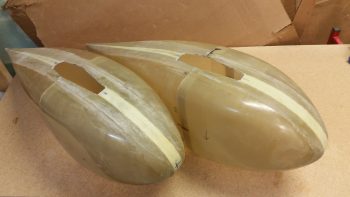
Voila! It finally worked [BARELY] and after a fair bit of wrangling –and 3-1/2 years!– I finally was able to mount the back part of the wheel pants into the forward assemblies for the first time ever!  And I bought these suckers from Sam James back in January 2013.

Wheel pants wheel starter holes

Here’s the first shot of my wheel pants assembled into one single unit per side! However, the fit is still really tight so the first order of business tomorrow is to give the flanges and receiver mating surfaces another intense round of sanding.

1st time wheel pants assembled!

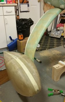
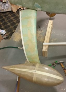
Excited to see actual, assembled wheel pants, I set them next to the gear strut for a quick mockup just to get a feel for the general size and shape.

Quick wheel pant mockup

Another shot of my quick wheel pant mockup.

Quick wheel pant mockup

Now that I know the wheel pants actually mate together (and that none of the vertical or horizontal centerline marks are off by more than 0.1″), I’m really happy and confident that the wheel pants should mount & fit nicely over the wheels and onto the gear struts!


Chapter 9 – Widening wheel pants

I started out today by using the Fein saw to cut off the overhanging glass from last night’s layups on the front side wheel pant pieces.  I then cleaned up the aft edges where I had just removed the glass.  I pulled the peel ply and cleaned up some of the peel ply strings and goobers, then I went to work on cutting the glass for the wheel pant aft side pieces (sorry, no pics of the front side pieces).

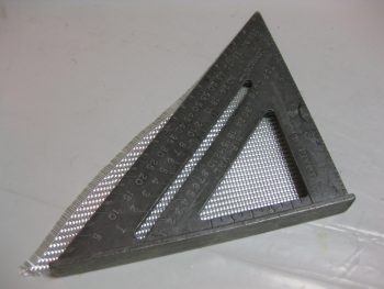
Kind of a fun point of note (at least I think so…) is that after all these years of estimating cutting BID at a 45° bias, I thought I’d do a quick check to see how I was doing.  Not too shabby.

45 deg estimate!

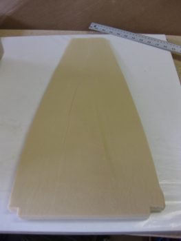
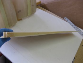
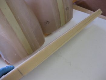
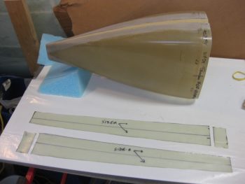
Back to work!  Probably the part I was dreading the most –because it’s challenging, and I’m lazy!– is cutting and shaping the wedges to widen the wheel pant aft side pieces.  It is a straight taper from 1″ at the front side to as near a razor’s edge as one can get it at the aft end.  Here’s the first piece I did.  Not horrible, but I did nick the front edge enough that it was just over 0.9″ vs a full 1″ thick.  So I notched the front and put in pieces of unblemished urethane foam to ensure the front edge was at 1″ thick.

Widening wedge ready to insert

Below are pics of the widening wedges.  The left pic is the first one I made.  The right pic shows the 1″ thick urethane foam edge marked up for cutting of the major material to be removed with a hack saw blade, then the rest “fine” sanded with a 17″ sanding block with 32 grit sandpaper (note that you can see the cured layups on the wheel pant front side pieces).

Widening wedgeWidening wedge

Here’s the first aft side wheel pant piece widened with the urethane foam.

Widening wedge glued in place

After I worked on the other wheel pant aft side piece a bit to let the glue harden, I then trimmed up the foam widening insert with a sanding block to match the existing sides.

Widening insert sanded

I then did the same with the other wheel pant aft side piece.

Widening insert sanded

Here’s a shot of both wheel pant aft side pieces trimmed and ready for glass.

Ready to glass!

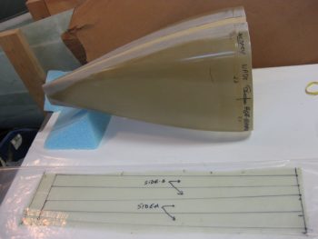
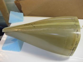
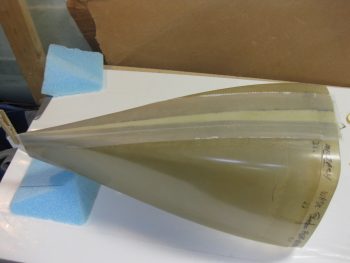
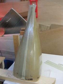
I wet out 2-plies of BID measuring 26″ x 6″ in a pre-preg setup.  I then marked the cut lines on the plastic.  Note that on the wheel pant aft side pieces the glass tapers into a wedge from 3″ at the front side down to 2″ at the aft vertical fin.

Glassing aft wheel pant sides

Here you can see the BID tapes’ taper more distinctly.  The small rectangular pieces are glassed onto the front lip first, then just barely covered on the aft edge by the BID being laid up down the spine of the wheel pant aft side piece.

Glassing aft wheel pant sides

As I was marking up the pre-pregged BID tapes, I made sure to use a CL mark in order to have a reference when laying up the BID onto the wheel pant aft side piece.  Below you can see that I’m just about to remove the top pre-preg plastic strip.

Aft wheel pant piece glassed

I then peel plied the BID layup on the wheel pant aft side piece.  Once I was done with glassing the first side of the first wheel pant aft side piece, I then set it aside under a heat lamp and started working on the other wheel pant aft side piece.  This allowed the first side to get just a little curing under its belt before laying up the opposite side of the wheel pant.

Aft wheel pant piece peel plied

Here’s the last external widening layup on the first wheel pant aft side piece.

Aft piece glassed - final side

And here are the 2 wheel pant aft side pieces all laid up with 2-ply BID tapes for widening. This is one task I’m glad to have behind me!  From here on out these widening steps should get exponentially EZ-er!

Aft wheel pant pieces glassed!

Tomorrow I’ll start off by cleaning the foam, etc. from the wheel pant front side pieces and glassing in a 1-ply BID tape.  I’ll also work on trying to knock out all the preliminary steps for installing wheel pants before moving on.


The Push Continues . . .

I am very close to starting back on the build, although it is quite amazing to me how much extraneous junk that I’ve had to contend with from selling my other house.  Dealing with this has been the long tent in the pole preventing me from getting back on the build.  And having been in a full-on repair blitz during the time leading up to the house actually closing, I’m just now really get all the tools & materials sorted out, organized, and put back into their proper places.  Additionally, during the last week I have been doing some odd & end stuff on the build, much of it stuff I was never able to really put together before since I didn’t have all the pieces parts in the same location.  As I’ve been getting my shop and house in order to build, I’ve also been focused on prepping –at least mentally & planning wise– for some other parts of the build. So, here we go.

Canopy Latch: A note that I’ve had for a while in the middle of my electrical switch diagram states to account for the panel space required by the canopy latch arm that sticks out horizontally into the space near the throttle handle.  I became acutely aware of how much space the canopy latch was really taking up when I sat in my buddy Marco’s Long-EZ specifically to note clearances, required reach to cockpit items/switches, and simple ergonomics.  It emphasized that the note on my switch diagram truly had merit, and that I must indeed account for this most necessary but intrusive component.

Thus, back at my hacienda, I finally got around to pulling out the EZ-Rotary Canopy Latch kit that I bought from Jack Wilhelmson (eznoselift.com).  I first (re-)inventoried all the parts to ensure I hadn’t lost anything over the years.  I then did a quick (re-)review of the installation procedures to get a feel of what I was up against.   My main current concern was of course the clearance with the instrument panel, and luckily with this setup the bearing block hangs down from underneath the longeron, and not straight out from the panel, thus giving me back the 3-4 square inches that I wouldn’t have been able to use on my instrument panel if I had installed the plans version of the canopy latch (pic below is from Jack’s website).
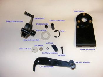
EZ-Rotary Canopy Latch

Electrical System:  Ah, yes, this beast keeps rearing its head.  Yes, yes, I am very close to a final system configuration, at least for now.  But stuff is still cropping up!  I equate it to trying to get all the dish soap out of a sponge: every time you squeeze it more soap comes out again!  So . . .

Pitot Tube Electronics & Components: Starting back in the beginning of 2013, my buddy Marco and I started brainstorming on a heated pitot tube design for our Long-EZs. Recently, Marco has been doing some truly amazing work on the electronics that drives the pitot tube heat.  In preparation for the electrical components that he’s developed for the pitot tube, I recently purchased another airspeed switch, and a new 3-position ON/OFF switch that has a momentary ON position in the farthest up point to reset the electronics if need be.  Marco has been detailing a lot of this on his phenomenal blog, What have I gotten myself into!

Control Stick Button Role Refinement & Swap: While down in Virginia Beach getting my first Long-EZ ride from my Marco, he at one point recommended that I swap my alarm momentary shutoff (left side of stick) with my A/P disengage & Pilot Controlled Steering (PCS) button (upper right of stick) on my control stick.  Well, I have to admit that I was a little resistant at first, but after pondering the idea and getting into the Trio Avionics Autopilot manual (and really finding out the advantages of using PCS), I actually had an epiphany while driving home one evening: since the top right button is the hardest to reach on the stick, then why not use it to control something that I will use very occasionally in the air, and almost exclusively on the ground.  Whereas with my new found understanding of PCS, I am confident that I will use that much more while flying.  Thus, I wanted the A/P button in a much more user friendly place on the stick, so of course I swapped them… which is simply code for I changed the CAD drawings for both the buttons’ electrical wiring connections.  Nonetheless, thanks again Marco for setting me straight!  ha!

Here’s a pic identifying my current Infinity control stick button & switch assignments.
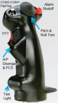
Infinity Stick Switch Assignments

AG6 Warning Annunciator (#2): As I was getting a bunch of these ‘final’ items squared away before jumping headlong back into my build, I submitted parts orders with B&C, Mouser & Aircraft Spruce.  Part of my order with Mouser was a direct result of my discussion with Rich from AircraftExtras.com, who gave me a bunch of great info on the AG6 warning annunciator.  To drive a myriad of warnings that would normally require an LED on the panel, I ended up calling a number of vendors to confirm the correct resistor values & wiring circuitry to use with their specific products.  Once I had the recommended resistor values in hand, I fired off an order to Mouser for all of them.  That also helped me to finalize which of my components would/could utilize the AG6 to annunciate an alarm condition.  One thing was certainly clear after I figured out what-was-going-where for my alarm annunciations, and that was that I didn’t have enough “where” to go to!  I needed another AG6 to handle the increased number of components connected to the AG6(s) to annunciate their alarm conditions, so I ordered a second one.
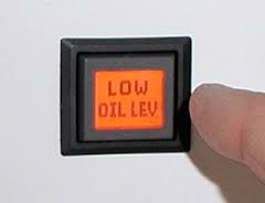
AG6 Warning Annunciator

The missing 2-Amp Circuit Breaker!  One day last week as I was updating my electrical system diagrams I ran across the 2-Amp inline fuse for the SD-8 backup alternator activation switch on the circuit diagram.  As I was assessing that switch specifically, for some reason the inline fuse didn’t seam like the right fit.  I pulled up the B&C install manual and sure enough it showed a 2-Amp circuit breaker, NOT an inline fuse! I then went back through the last couple of versions of Bob Nuckoll’s Z-13/8 system architecture diagrams and…NO inline fuse!  “Huh?!” sez I, “Where did I get the idea for placing a 2-amp inline fuse there?”  Well, I finally found it in an old version of the system diagram that I had started with back in 2012! I guess it pays to review, or, well, it actually costs money since I had shell out some more to buy a 2-Amp Circuit Breaker.  Regardless, I’m just glad I found my oversight & corrected it ‘early’ on.  By the way, this scenario is exactly why I’ve been critically assessing literally every component in my electrical system!

Engine Cowling Installation:  Over the past few days I also wanted to get a lot smarter on exactly how the upper & lower engine cowlings would be mounted, specifically the hardware to do so.  This meant getting much smarter on Camlocs and the Skybolt Croc system.  I researched a fair bit and bought a few basic Camloc components in my last Aircraft Spruce order to test them out. In addition, I’ll be using Mike Melvill’s 82° stainless steel hex-drive screws that he discussed in the Canard Pusher newsletter (CP 73).
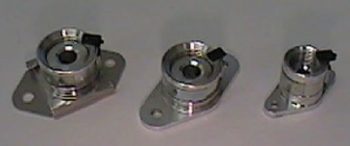
Skybolt Adjustable Receptacles

Electrical & Aircraft Component Weight:  Upon receiving the new 2 amp circuit breaker and AG6 warning annunciator I decided it was time to spend a good hour to update my estimated aircraft weight worksheet.  I added all the new components, eliminated old ones, and weighed a number of components that until previously I only had factory listed or estimated placeholders for.  When I finished, my Long-EZ had gained 10 lbs, with its new estimated weight still just under my max goal weight of 1,000 lbs… but just barely! And by barely I mean less than a pound under.  The good news is that I have a lot better idea of what is going into my airplane and now have hard weight data vs. estimated/unknown data variables.  Obviously, since I now have a lot of this stuff on hand, I can get the actual weight of each item.  Moreover, I have padding built into the weigh figures for the electrical system, avionics/equipment, and main airframe components.  Thus, I suspect to be somewhere near 1,000 lbs. for my final weight, ± about 30 lbs. (yes, yes, more likely plus than minus!)

Integrated Backup Battery System (IBBS) model selection:  One thing that I did in the planning of my future components order is to mock up the fit of my TCW Technologies IBBS in the nose where I plan to install it.  After a discussion with Marco on the W&B on his new Long-EZ, I figured a pound of extra weight gained by moving up from the 3 amp hour IBBS unit to the 6 amp hour unit would actually be beneficially.  However, there’s just one problem with moving up to the bigger 6 AH IBBS unit: it won’t fit in my planned location!  No worries though since the original 3AH IBBS unit that I had initially decided on will work, so back to square one.  Another decision crossed off the to-do list.

Fuselage Trueness, Squareness & Alignment:  At some point after returning back from overseas I took a myriad of different measurements on my fuselage, from a myriad of different locations on the fuselage: bulkheads, Left/Right/Center, angled, etc. to assess & evaluate to what extent my fuselage is true, square and aligned.  If you’ve read much of my blog you know that my fuselage is not perfectly aligned.  That being said however, I had never taken the time to really sit down and figure out what my measurements meant. After really pouring over them for about 15 min, I concluded that my fuselage is acceptably square between the firewall and F22 bulkhead.  Another thing I did when I made my measurements was to clamp a 6 foot level to the front & aft sides of my fuselage and then measure the outboard distance between each straight edge/level.  What I came up with after multiple measurements, and after recently analyzing the data, is that the difference between each side (at essentially B.L. 36L & B.L. 36R) is just a hair over 1/8″ off.  Not bad, and easily correctable when I install the CS spar & canard to the fuselage, respectively.

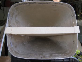
Engine Mount Extrusions installation:  This next thing I did was something that solved a question that has been gnawing at me for some time: How exactly will my engine mount extrusions be mounted to the fuselage/CS spar/longerons?  Well, between last night and today I finally measured all the critical players and worked out an installation solution. Since my aft upper & lower longerons are thicker (since I was originally planning on having a much wider fuselage all the way back including the firewall) AND my back seat is about 0.8″ wider, I needed to detail out exactly how thick the extrusions needed to be, and how many plies of BID to use to get the spacing correct.  As you can see, on the lower mounts I’m adding 6 more plies of BID along the sides and using a 3/16″ thick 2024 angled aluminum extrusion.  On the top I’ll be using 1/8″ thick 4130 steel extrusions with 4 extra plies of BID on the sides of the extrusions.  The weight penalty for all this is about 1.5 lbs.
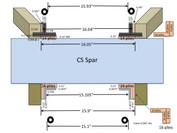
Engine Mount Extrusions

Finally, in prep for my upcoming reintegration back into the build, I performed the ceremonious refilling of the Flox and Micro containers.  And cleaned my respirator masks.  (Hey, if this isn’t a clear indication of getting on with the build, I don’t know what is . . . ha!)
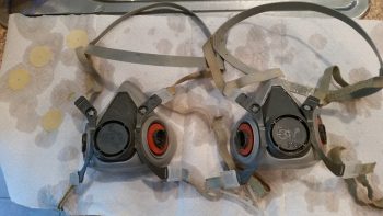
Cleaning respirators


Chapter 13 – Grazing & Raising!

Today was quite the beautiful day here in Northern Virginia, so after messing around with my school work for a couple of hours, getting my motorcycle battery charged up enough to get it started and out for a quick scoot, and then spending just over an hour on the phone with my building nemesis Marco (ha!)…. I finally got into the shop!

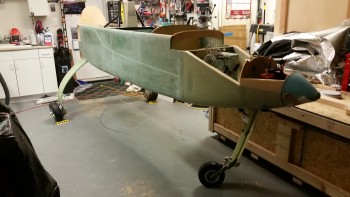
My main goal for this afternoon was to get the fuselage off the dolly and into its grazing stance, which I did as you can see below.  Before I actually offloaded the fuselage from the fuselage dolly, I did a bit of Spring cleaning in the shop and attached the rollbar and headrest to the fuselage.

Fuselage in grazing position

My next task was to install the battery in the nose and connect up the wiring leads to get the nose gear to extend and finally get this bird on all 3 wheels!

Fuselage in grazing position

First, I wanted to get a couple of shots of my grazing fuselage from the aft end.

Fuselage in grazing position

Especially this shot, where the nose is fully resting on the nose bumper, which of course is the aerodynamically clean shaped nose bumper that my buddy Marco CNC’d out of a hockey puck.  He did a fantastic job on it!

Fuselage in grazing position

I then got the battery installed into the nose battery compartment and the power cables clamped into place.  Note in the pic below you can see the nose gear backup battery immediately aft of the main battery.

Nose battery compartment

I shot a video that covers the majority of work I’ve completed over the last few months. Then, at the end of the video, I raise the nose by extending the nose gear for the first time during this build.  Note that I merely strapped in the battery, attached the leads, and then shot the video.  There was no previous testing to ensure it worked and the initial nose raising in the video is just that, the initial nose raising in real time.  I’m just glad it worked! Whew!

I took one final pic of the fuselage on all 3 wheels before closing up shop for the evening. This of course is another huge milestone for this build!

Ready for taxi!

Over the next few days I’ll be doing a final check on the wheels to ensure the toe-in is correct and set for one final time!  In addition, I’ll also be prepping for installing the wheel pants.


Chapter 9 – Flaring tool & heat shields

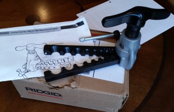
First off, UPS delivered my Ridgid 37° flaring tool yesterday morning.  This tool will enable me to flare my 3/16″ stainless steel brake tubing, thus allowing the final pieces to placed into the brake line system.  Now, this tool’s specs does not specifically state that it’s rated for stainless steel, but many of the reviewers on Amazon did clearly state that they used it with very good results on stainless steel.  So I figured I would give it a try.  I will tell you that it is much bigger than it looks in the pics, and this thing is a heavy, robust beast.

Ridgid flaring tool

Secondly, I’ve been doing a fair amount of research on my toe-in dilemma and I’ve decided to pull the wheels, configure the fuselage upright without the fuselage dolly in the way and do one final toe-in setting to get them to specs.  After reviewing both the plans, what other canardians have done, and even the standard on other types of aircraft, I’m concerned my toe-in is too much, even for a heavier than plans bird.  I would probably not mess around with it if it were, say, 0.5″ total vs. the 0.45″ total called out for in the plans, but I’m significantly over at 0.6+”.

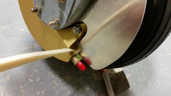
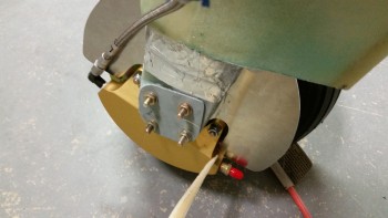
Finally, I’ve been updating my to-do task list and one thing I forgot to add came up today when I took a couple of pics to send to Marco earlier.  I was pointing out how the aft tab of my right heat shield was just barely kissing the brake caliper… as I’m pointing to in the pics below.  I’ll trim about 0.1″ off that area when I remove the wheels (AGAIN!) to set the final toe-in.
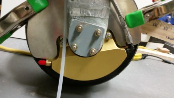
Heat shield interference

Heat shield interference

As you can see, the left side heat shield clearance is fine.

Left side heat shield clearance good

This morning I got an order from McMaster-Carr with my 1-1/2″ stainless steel cap head screws to replace the 1″ screws Marco had included with the nose bumper.  Since I had to install the nose “Exoskeleton” over the 1/4″ thick 2024 aluminum skid plate that has K1000-4 nutplates riveted to the back side of it . . . well, clearly I needed longer bolts.  This makes today the first time that my nose bumper has been officially mounted on the lower nose!

Nose bumper permanently mounted

As for the build, I’ve clearly not been in the shop much lately.  This is due primarily to my Commercial Pilot Rating ground school which, to be honest, is kicking my butt as far as the amount of time required to complete the course work.  I’m trying to get ahead of the power curve, but then I fear once I start flying, the pace will only worsen.  We shall see.  I do honestly believe that once I can stop playing catch up and get into a good battle rhythm, that more work will get done on the plane build.


Chapter 9 – Brake Line Install

I started today by continuing the design on the belly air scoop for the ram air intake.  I spent a good amount of time researching the intake nozzle shape & checking my options for what bell mouth-shaped aluminum intakes are available for sale online.  So far I haven’t found exactly what I’m looking for, so I’ll keep looking as I continue to dial in the shape, design & configuration of the air intake scoop.

Designing belly air intake

My main focus today was to get down to brass tax to answer my #1 burning question at the moment concerning my final brake line connections: stainless steel or Nylaflow? (both of which I have on hand).  What I don’t have on hand is a flaring tool for the 3/16″ stainless steel tubing I have on hand ($$) or the fittings I would need to connect up the Nylaflow into my current configuration ($).
The first thing I needed to find out is if the stainless steel tubing would even fit into the channel tubing I emplaced on the aft side of the main gear fairings.  Well, the stainless steel tubing, being a small diameter, was easily bent by hand and with just a little bit of effort & cajoling I got it to slide into the fairing channel.

Testing stainless steel brake line install

Below is a closer view of the inboard side.

Knowing that the stainless steel brake line can be fit into place easily enough, I then pulled the trigger and ordered yet another tube flaring tool that can handle flaring 3/16″ stainless steel tubing.  I don’t have the model or specs in front of me but when I get it in hand & use it I’ll give you a report on how it works.

Testing stainless steel brake line fit

Below is a shot of the outboard side gear with the stainless steel brake line sticking out.  As you can see, there’s plenty of tubing to work with which will allow me to most likely create a service & anti-stress spring loop at the hell hole side of the tubing.

Testing stainless steel brake line fit

I threw together an ACS order along with the flaring tube order which I’ll finalize tomorrow morning.  Again, tomorrow is Monday so it will be a school day & night, so no building will get done on the airplane.


Chapter 9 – Main Gear Install Plan

Today I didn’t make it to the shop to do any actual physical work.

I did however spend a good 7 hours planning and sequencing out the remainder of my Long-EZ build.  Specifically, I spent the majority of time creating my build plan & task list for installing the main gear, axles, wheel & brake assemblies, tubes & tires, dealing with toe-in, glassing the gear fairing, identifying required tools, hardware & materials, and the eventual install of the wheel pants, as well as well as a myriad of other associated main gear related tasks.

To finalize this plan I reviewed the plans Chapter 9, Canard Pusher plans changes, Matco wheel/brake install manual, Eureka CNC gear fairing install instructions, CSA articles, Sam James’ wheel pants install manual, builders’ websites, forums, and my compilation of main gear related build notes over the years.

Since I now have the lion’s share (about 90%) of the specific main gear install plan in hand, I can go back to finishing up nose & elevator stuff as I start transitioning into focusing on the main gear final install.


Chapter 13 & 22 – Inching Closer!

Today wasn’t a huge build day as far as shop work.  I spent a little over an hour doing some much needed research & planning on my upcoming steps, which allowed me to figure out my glass cut sheet & layup schedule.

I then ran around the next half of the day running errands, etc, and then I headed south to Harbor Freight since they were having a huge parking lot sale & stuff is normally way less expensive during these sales.  So I picked up a number of consumables & items for the build project, including the much needed storage bins for my electrical connectors.  Instead of keeping 20 baggies lying around on the table, I now have them all consolidated into one location… in mini-bins no less inside the larger one.  You can’t beat that for storing small items like electrical connectors!

AMP CPC Connectors

I watched a bit of playoff football before heading down to the shop where I spent a good hour and a half organizing it.  I bought a few other work bench storage bins that should help keep things a little bit more organized.  I did clean the floor a bit and organize most of my foam scraps, but the shop really does need a good cleaning, which it will get after I glass the nose.

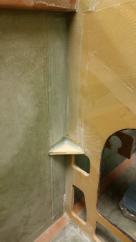
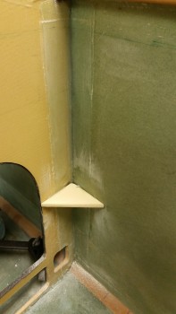
I then continued working on glassing in a couple corner reinforcement H250 1/4″ thick foam plates at the forward (so behind) side of the panel & the fuselage side wall.  Since I already had the instrument panel clamped forward a bit, and had already started down the road of getting it to stay a little straighter by coercing it forward with the nose wheel well cover (NB), then I would continue on with my quest since this is a significant to do item on grand list of things that need to get done.

After measuring and cutting the corner triangle pieces, I mixed up some 5-min glue and put a dab on each end of the foam and on the corner.  Then on the edge of foam in between the 5-min glue dabs, I added some flox.  I pushed these reinforcement triangular pieces into place and held them for a few minutes while the 5-min glue set up, which you can see in the pics below.

Right panel corner straightening braceLeft panel corner straightening brace

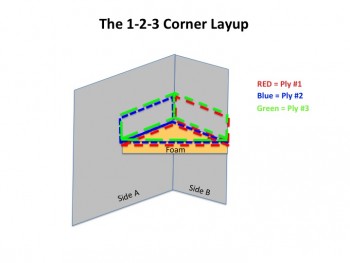
I then added a flox fillet and laid up 3 plies of BID in what I call the 1-2-3 corner layup method.  I have no idea how it compares in strength to other conventional corner layups, but we’re talking flox fillets and a minimum of 2 layers of BID per corner, so I’m thinking it should do the trick strength-wise.

As you can see below, there’s only 1 layer that ties the first 2 plies together in the corner, but you have a minimum of 2 plies of BID per each wall, all converging on the face of the foam where you end up having 3 plies of BID.  And it’s fairly EZ & fast since you’re only dealing with 1 ply total that traverses a 3-sided corner.  The other 2 layups are simply corner layups.

Still, I’m thinking it will add a decent measure of reinforcement to the corners to help keep the panel straight.  I’ll leave it clamped overnight, then check the affect that these corner reinforcements have on the panel’s alignment.

"1-2-3 Corner Layup"

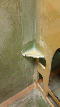
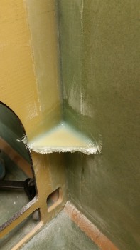
Here is both the right and left corners glassed with 3 plies of BID each.  I should not that the height of these are as closely matched to the height of the arm rests, so that there’s no infringing upon real estate for switches, electrical, etc.  I ran a piece metal down from about where the elevator control tube will travel from the elevator torque tube to the control stick, and although it will be tight, as of right now I don’t foresee ANY interference.

Right panel corner straightening brace glassedLeft panel corner straightening brace glassed

I then took some time to tweak the up limit microswitch, which is much more challenging to do now since the forward NG30 nutplate tabs keep me from pulling the nose gear motor actuator tube above the NG30s to gain access to the back of the microswitch screws.  Now I have to bungee tie it up and reach one hand from the bottom while the other one twists the screw driver on the top side.  I got the travel I wanted, but then realized that it won’t be enough since the wheel fork assembly needs to be higher so that the NG15 bolt heads are above the bottom skin and thus won’t cause the gear doors to protrude when the gear is in the up (closed) position.  I’ll work on that tomorrow.

Here’s an initial shot showing that the nose gear strut front edge is above the channel sides, but as I mentioned before, the NG15 bolt heads do not clear the bottom fuselage edge.

Setting gear strut up travel

Tomorrow I’ll check my corner reinforcements layups, then reset the gear up limit microswitch, then l start prepping the fuselage to flip and get some nose sanding in.


Chapter 13 & 22 – Brake & Line Dance

Today I took a few hours to get some well-needed organization of my hardware knocked out.  With all the smaller hardware that I’ve ordered over the last month, I really needed to put it all in some sort of order to make finding stuff occur more quickly and easily.

Due to it being Christmas eve I didn’t get back to the build until later in the evening, and by then I didn’t want to make any noise cutting the foam, so I worked on getting the brake system figured out.

I pulled the right brake line coming in from the aft of the fuselage and cut it shorter, re-flared it, and then connected it back to the mini-bulkhead,  I also cut the right brake line that connects to the parking brake valve, and then flared it as well.

Connecting brake lines

I then connected the parking brake valve to the freshly cut & flared brake line to check fit & alignment.

Brake line connect to Parking Brake

I then cut, re-flared & remounted the left side brake line that connects to the mini-bulkhead fitting.

Left brake line refitting

I then cut, rerouted slightly and flared the left brake line that leads to the parking brake valve, finalizing the aluminum brake line work in the nose.

Brake aluminum tubing completed

I then connected the other side of the parking brake valve with the nylon brake line included with the Matco parking brake valve

Parking brake to master cylinder tubesI had originally planned to mount the clear brake reservoirs on the nose sidewalls, but after messing around with the nylon tubing for a bit, I decided to wait and better figure out the specific configurations and mounting locations for the reservoirs.

Parking brake to master cylinder tubes

I then test fitted the main power cables in order to finalize the locations of the cable holes transiting from the NG30 side of Napster into the battery compartment.  I wanted to get these holes drilled before I installed & laid up the floor plans in the battery compartment.

Main power cable pair test fitting

I then drilled the holes for the main power cables through Napster (not shown), and built the main 6 AWG cable that powers the Main Bus (connecting it to the battery contactor).

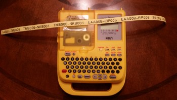
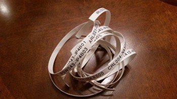
I started by printing out the labels for the 6 AWG main bus power cable, and also the labels for the 8 AWG cable that connects the starter to the starter contactor in the engine compartment.

Bigger wire labels

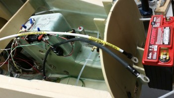
Below is a shot of the 6 AWG main buss power cable that I constructed to finalize the angle and location of the holes to be drilled for this 6 AWG main buss power cable, and the primary ground cable (black cable below) that will be paired up with the power buss cable, both coming from my electric components “tree” –again, I gave it the officious moniker of “Triparagon”– to the battery compartment.  This pair of power cables will enter the battery compartment through one of three holes that will be drilled for cable/wire runs. Actually, at least one, and maybe even 2 of these holes will technically be a pair of holes, one for each cable.  The holes will be a work in progress so it depends on how the cables & wires actually fit.

Main buss power cable

Tomorrow is Christmas so I’ll be busy being Merry (ha!), but I do plan on getting an hour or two in on the build (my kids are grown & live on the West Coast so I don’t have any overriding social commitments… sooooo… sniffing some epoxy on Christmas won’t get anyone riled up).


Chapter 13 & 22 – It’s electric Baby!

Again!

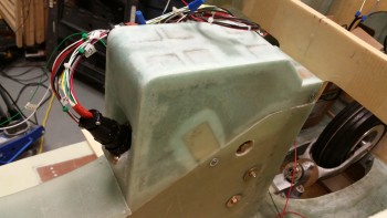
Here’s another shot of the installed & wired NG30 Aft Nose cover … not sure why I took this pic, or if it’s a holdover from yesterday, but here it is for your viewing pleasure!

Mounted NG30 cover & gear wires

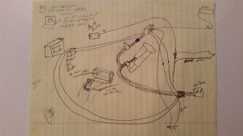
I also thought I would throw this up on the site before I threw it away.  It’s my original chicken scratching diagram of the EZ Nose Lift nose gear wiring.

Initial chicken scratchings

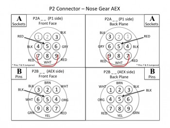
Finally, as for diagrams, I spent a few hours last night and a couple hours this morning making sure that I had my connector pins diagrammed out on paper.  As of right now, I have about 7 AMP CPC connectors planned for use in my electrical system: the Infinity stick grips, throttle handle switches, etc.  Each of those will have a pinout page depicting information on what wires are where & wire colors, and what connectors are being used, pins, sockets, notes and any pertinent info.  Below is the first iteration of the P2 connector. Also, in addition to the P2 connector diagram, I finished the P1 diagram.

P2 Connector Pinout Diagram

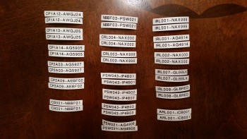
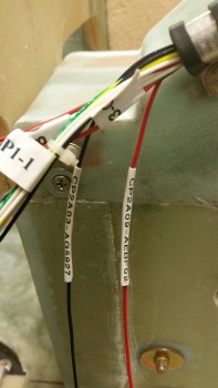
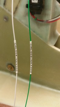
Later, while watching some football today, I took my list of wire label codes that I spent a couple hours last night researching & building to use to print out a bunch of wire labels.  I’m fairly certain that I’ve already spelled out my code schema in detail here on this site, but after I work any wrinkles and kinks out of the system, I’ll touch base on my wiring code again.

In essence, I have two 6-digit codes separated by a dash that make up a wire label and then heat shrunk to the wire in an oriented sequence to depict where the wire is coming from & going to component-wise, and what location in the aircraft the wire is coming from and going to.

Printed wire labels

Here are the wire labels cut and ready to heat shrink onto the wires.  I have them in pairs because my standard is to place a label about 6-8″ from each end of each wire.  On longer wires there may be a third label thrown on approximately halfway the length of the wire.

Cut wire labels

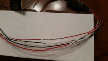
My first test case for the heat shrink wire labels was the landing brake wiring.  I was very impressed with the legibility of the labels and the ease & speed of the whole process from printing the labels to heat shrinking them into place.

Landing brake wire labels

Since I have the nose gear wiring harness mocked up, I didn’t heat shrink some of the wires in place.  I merely shrunk them down to a significant degree, maybe 80-90%… enough that they wouldn’t easily slide off, but that I could still slide them in their final locations (past the Adel clamps) later and then do a final heat shrink to keep them in place.

Below left is the pair of AEX power wires with incompletely shrunk wire labels, while in the right pic those labels were heat shrunk down to their final position.

Wire labels shrunk 90%Wire labels shrunk in place

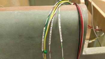
Here’s another couple of pics of my wire labeling endeavors this evening.  The labels in the top pic are in their final location, whereas in the bottom pic those labels will be moved into their final position and given a final pass with the heat gun later.

Wire labels shrunk in place

Wire labels shrunk 80%

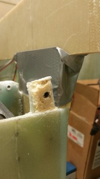
I then moved on to a dirty little task:  I cleaned up the ugly layups on the aft screw posts (or tabs), and then cut some of the foam away near the remaining good glass to create a trough for flox to go into to create stronger flox corner.

Here’s the left side aft screw post prepped for glass.

Ugly duckling

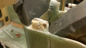
And here the right side aft screw post prepped for glass.  Oh, and I guess I should have mentioned that I intentional set these posts very slightly inboard so that I could lay up a ply or two of glass on the front (outboard) side while still being able to seat the aft cover end around the posts.  I did this by applying another 3-4 layers of tape –to emulate the thickness of BID–on the inside of the aft cover when I originally 5-min glued these screw posts into place.

Gnarly glass!

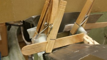
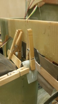
I only used 1 ply of BID after apply flox into the trenched edges, but the glass didn’t want to stay down so I forced it into place using clothespins.

Ugly layup round #2

Here’s a shot at another angle.  I’m calling this ‘Ugly Layup Round 2.’

Ugly layup round #2

Tomorrow I’ll start on the remainder of the nose to get it completed.