One small step at a time

I didn’t get much done today on the build, although I did make progress.

I tried to get down to Home Depot during a 1-hour window of time where it was NOT supposed to be raining, but, alas, the weatherman was wrong and I ended loading and unloading the remaining lumber for my fuselage dolly in the rain.  This is the main reason I have no pics of the event, since I was scrambling to get it all done as quickly as possible.

I dumped the wood in the garage, quickly wiped it down and then had to go meet a real estate client.  After a few hours with my client, I was across town near a buddy’s house & we ended up going out to dinner.

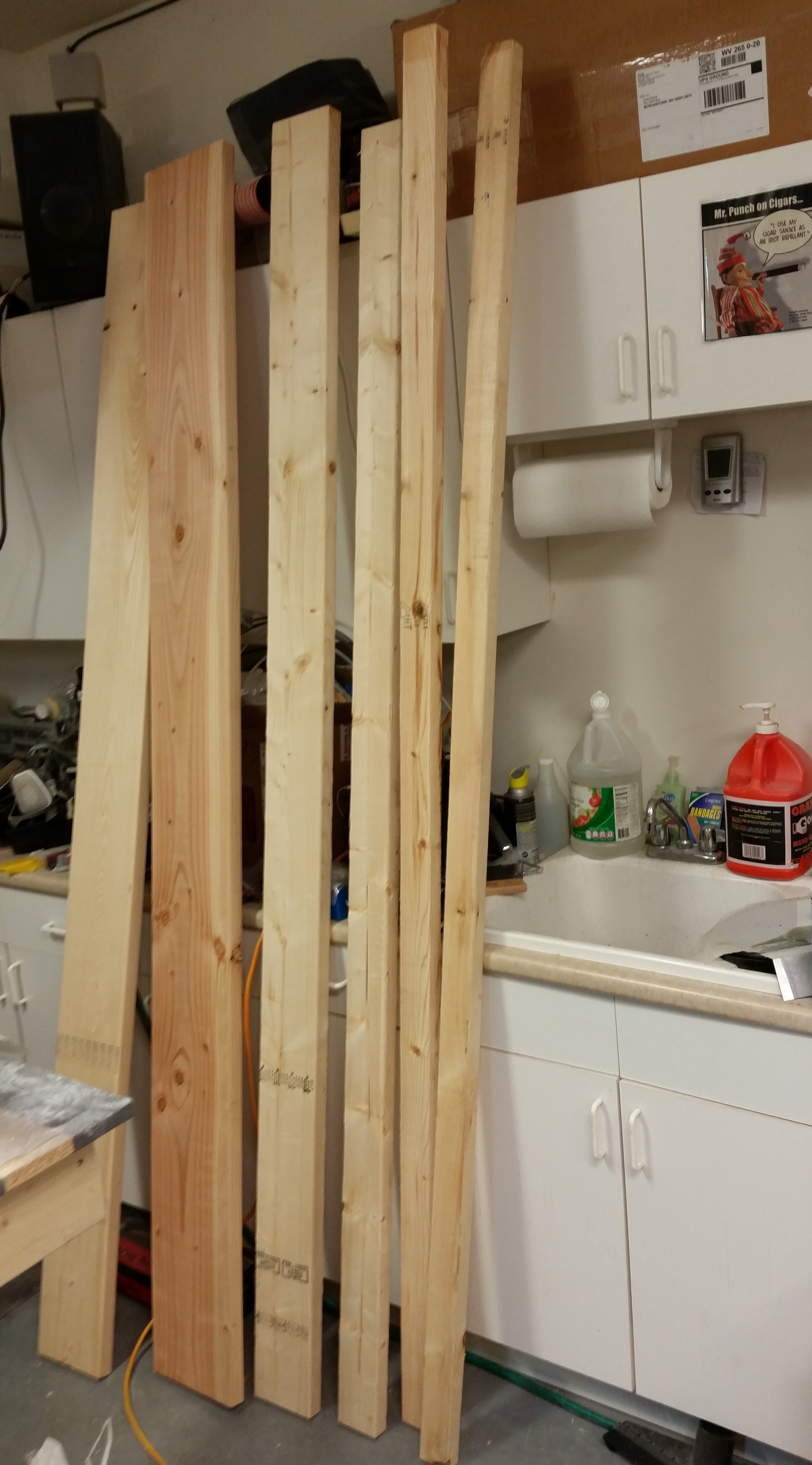
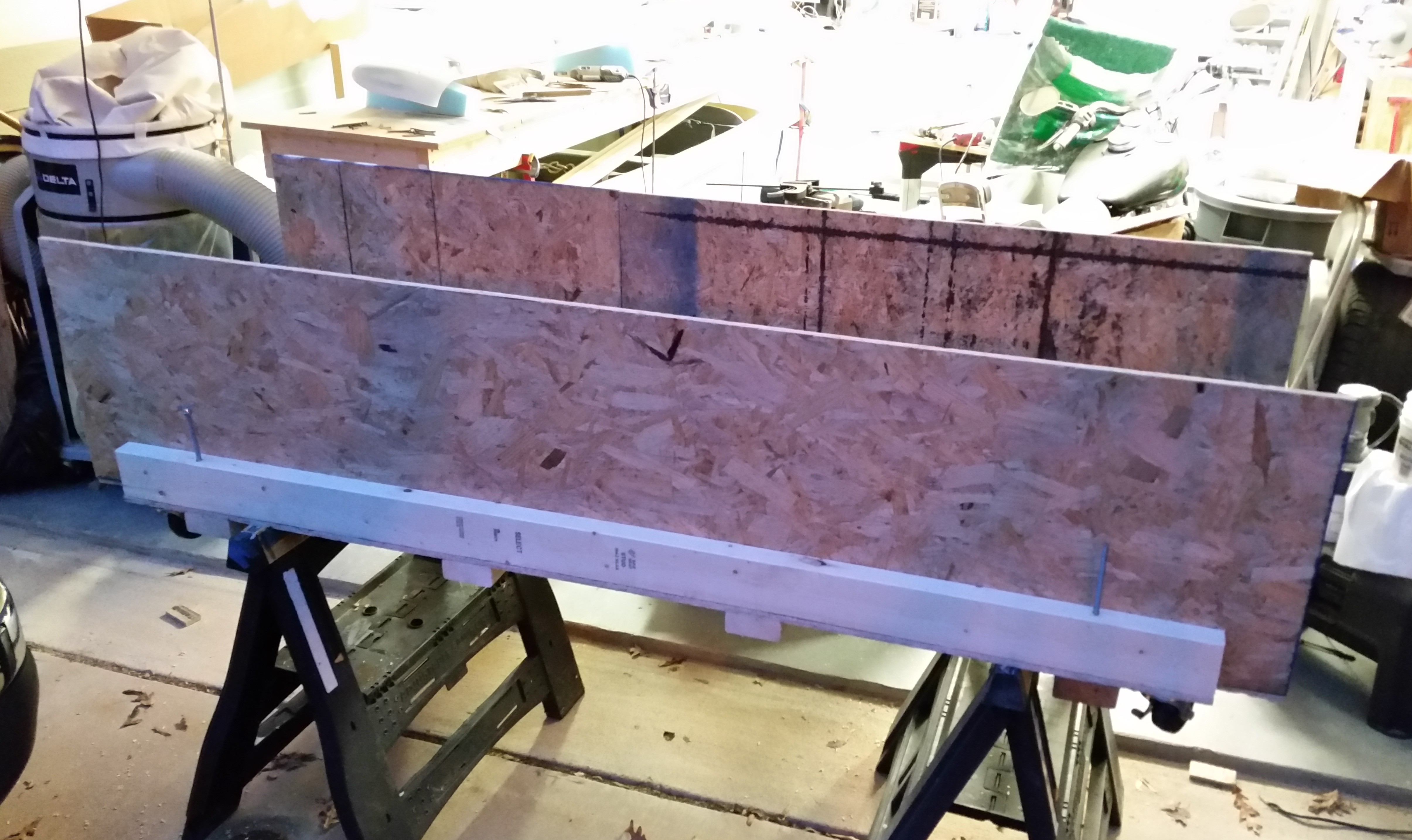
Thus, besides acquiring the required wood to finish the fuselage dolly, the only significant thing I did for the build was take the pic below upon returning home (there’s actually a few more pieces in the back room as well).

Fuselage Dolly Wood

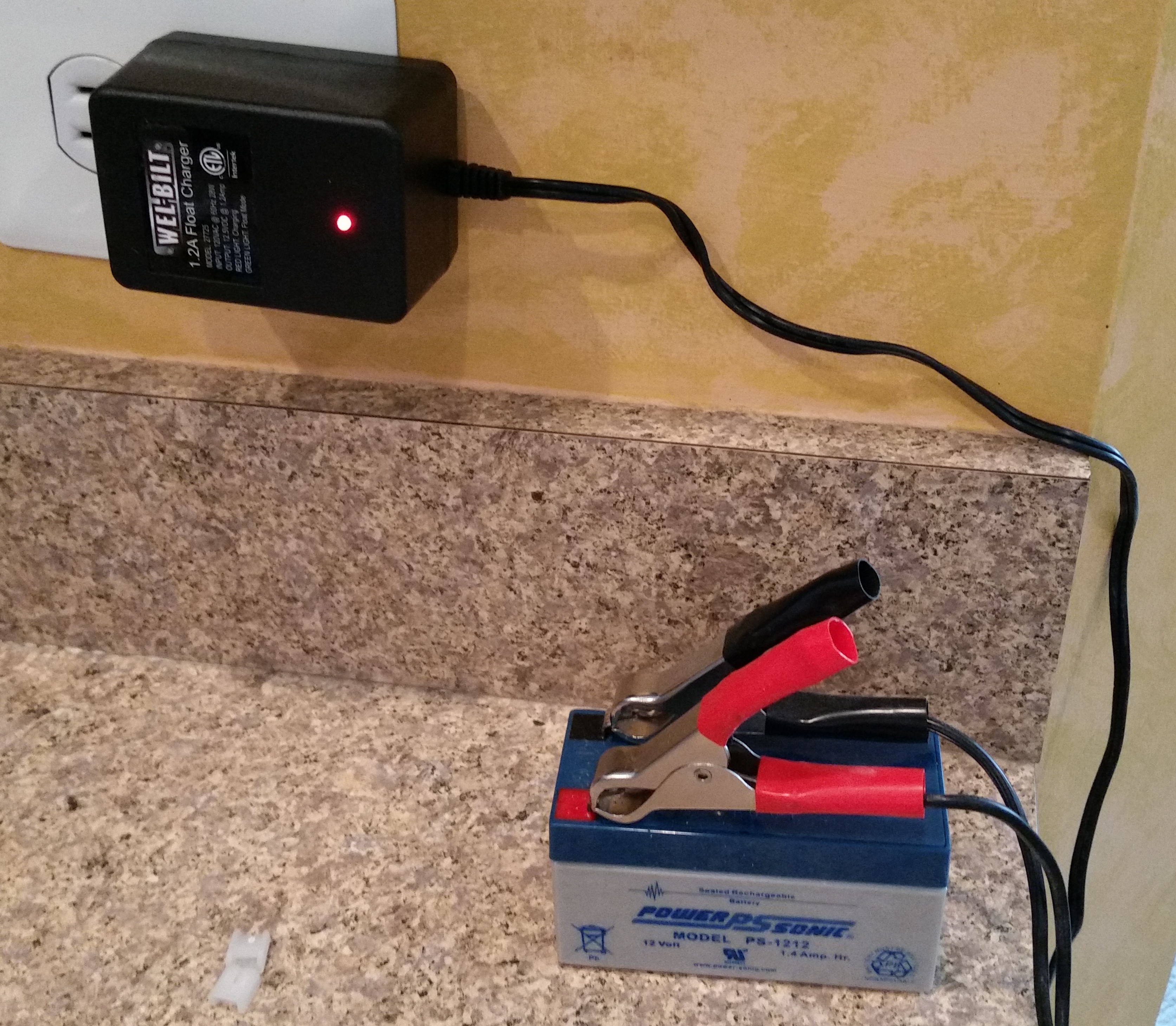
Oh, and I grabbed a battery tender from the garage & put the small emergency back-up battery for the nose gear on a trickle charge to get it ready to go when I eventually wire up the nose gear to test it out.

Charging gear back-up battery

Tomorrow I’m hoping to get quite a bit of stuff knocked out between the canard, the nose gear NG30s and the fuselage dolly before I go out to dinner tomorrow night with another buddy of mine who is in town this week for work.

No sanding today . . . sluffing off!

After my meeting at work today, I grabbed lunch on the way home and went over my plans for the dolly I will be building for the fuselage, ala my buddy Mike Beasley.  Since I was close to the final design, I knew that I would actually need to build the base to get enough data to finish this sucker.

First off, why am I doing this now?  (Instead of planting my butt in front of the canard and sanding away . . . ???).  Well, the reasons are: A) To take a break from sanding while still being incredibly productive!, and [more importantly] B) I don’t want to get to a point where I am so frustrated with positioning, repositioning & flipping the ever-weight-increasing fuselage that I work in a less optimized state until then, and then have to take time out to build this thing.  Also, with my buddy’s fuselage incident where it fell off the saw horses & smashed his rear longerons, I figured I would pay the piper up front and get this fuselage dolly knocked out early so I can enjoy its functionality.

Here are the key features and requirements for this thing:

  • Had to be mobile (i.e. on wheels)
  • Had to be low enough when working IN the fuselage & high enough when working ON the external fuselage (adjustable height . . .  more to follow!)
  • Had be able to be leveled as a surface–not shimming the actual item, but leveling the platform itself. (Leveling screws . . . aka, poor man’s outriggers)
  • Secure canopy storage (since I would have the length and width, I might as well make the underneath area useful and store the canopy in a wood box)
  • Optimized stabilization of the fuselage (when the fuselage gets its nose, etc. more weight will be added and more awkwardness in controlling it will ensue, thus multiple tie down points are a must)

So, while sitting having lunch 2 blocks from Lowe’s, I realized that I had met all my critical design goals and I could begin construction immediately.  I bought a couple of sheets of flooring material (OSB) and a few 2x4s to get me started.  While checking out the cashier asked me if it started raining yet!  So with that info in hand I rushed to get to the house and get some wood cut.  It did sprinkle on me quite a bit, but never got into an actual downpour, thank goodness.

After cutting the wood, I started constructing the base of the fuselage dolly.  Here’s the very bottom of the dolly.  I’m about to attach 4 each 2×4 cross beams & the wheels to the bottom of this thing.

Bottom of fuselage dolly base

Here’s the base turned upright.  If you look closely you can see the wheels near the corners (mobile) and the four threaded leveling screws just inboard of each corner as well.

Top of fuselage dolly base

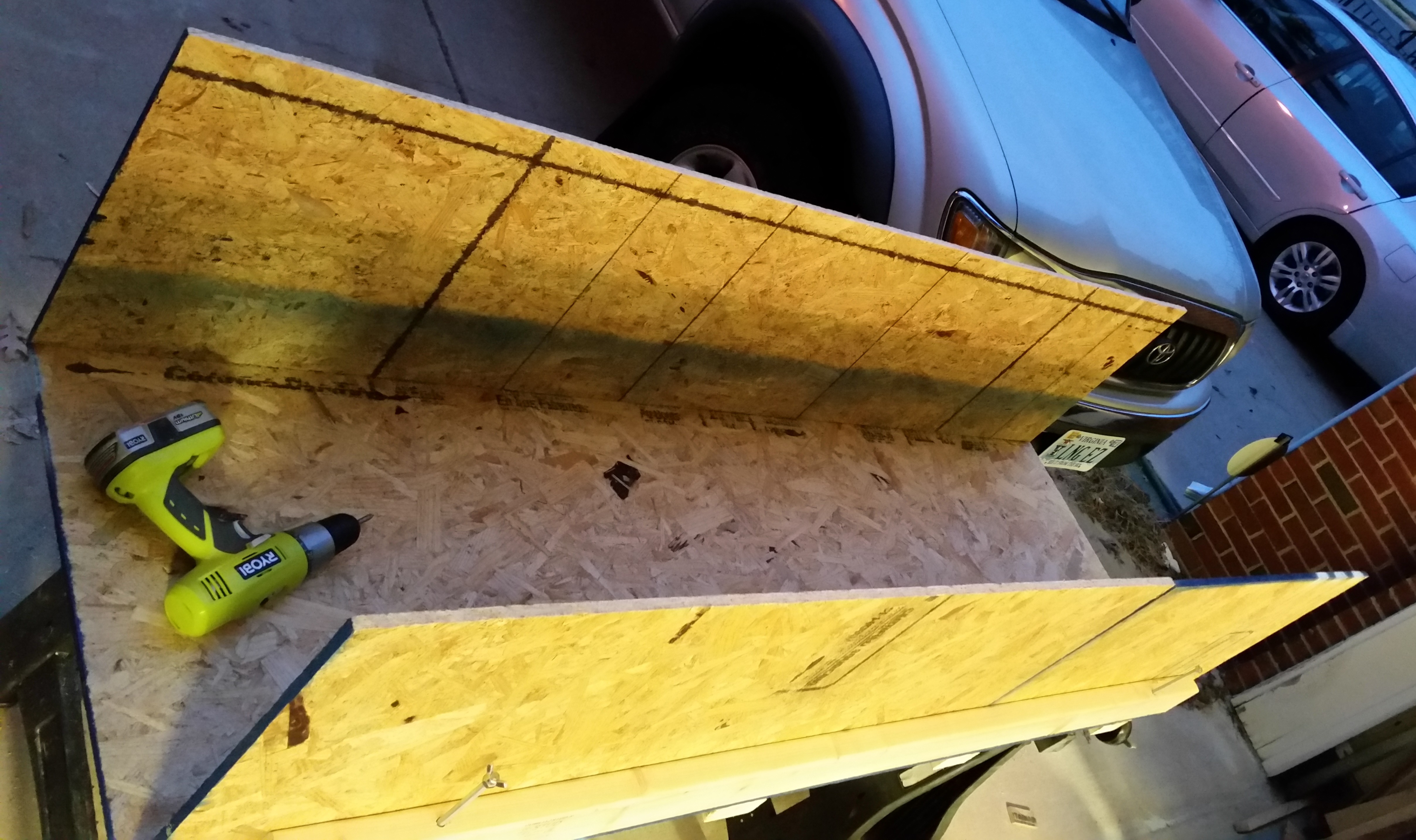
Here are the OSB sides attached.

Side walls added to fuselage dolly

And the future temporary home of the canopy.

Canopy storage area

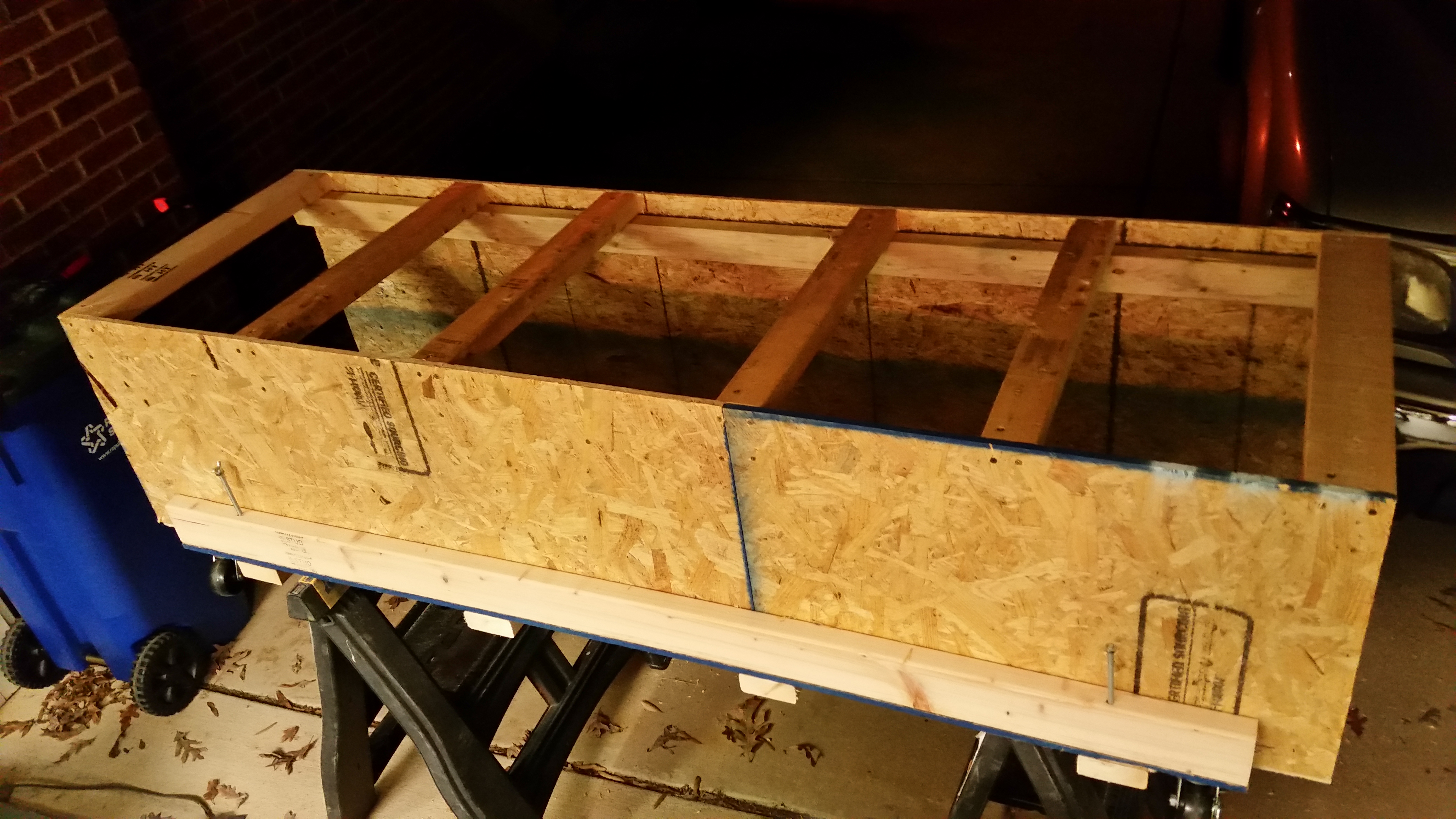
I added the top cross joists that sit on a 2×3 stringer that runs the whole length of the dolly on each side.

Top cross beams - fuselage dolly

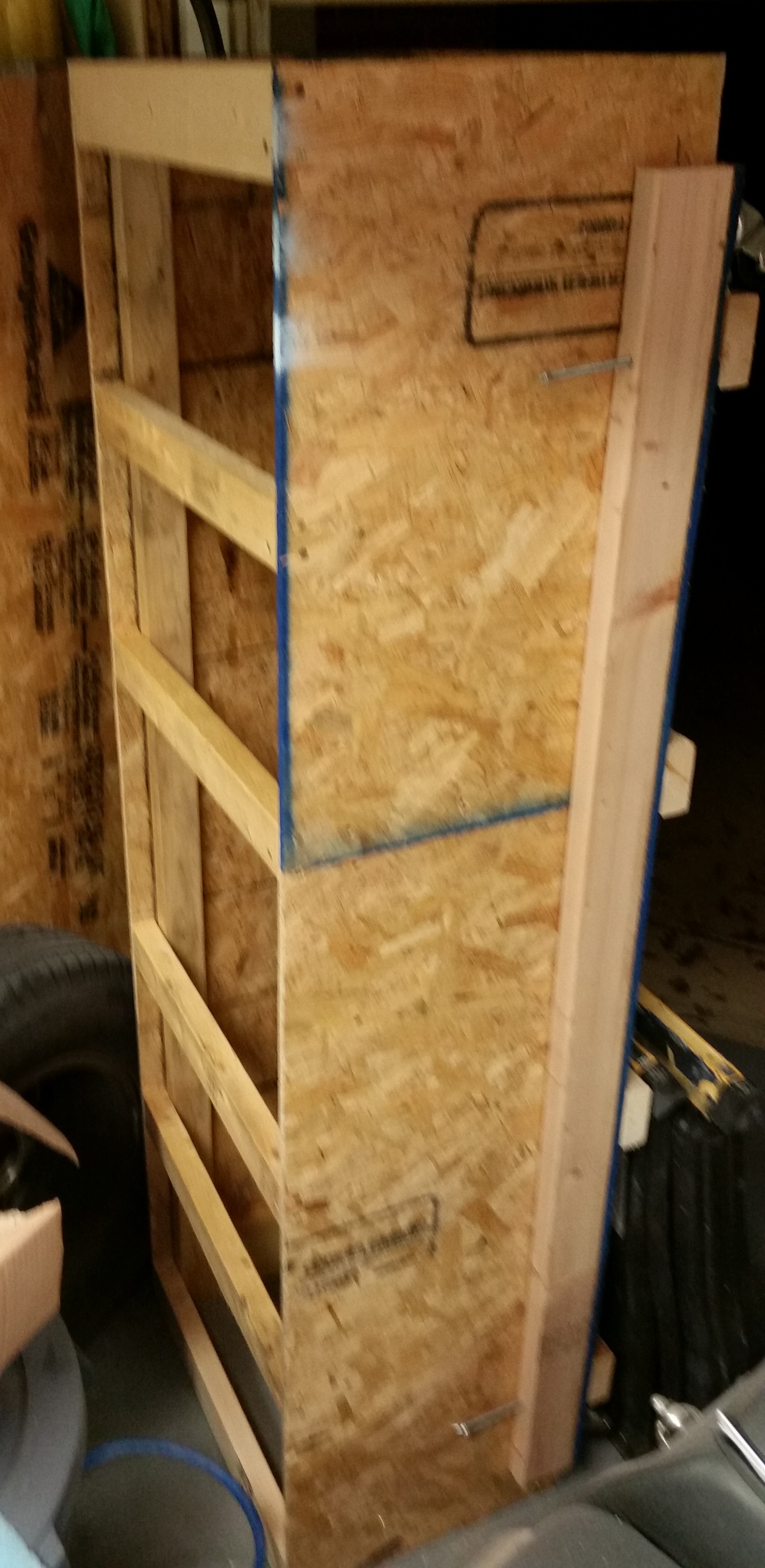
After getting to the point where I needed to cut more wood, and for some parts buy the wood to cut it, and get some more hardware, I cleaned up my work area and stowed my new creation up on end.

Temp storage of fuselage dolly

I then ran off to Harbor Freight to pick up some “supplies” . . . mission operational security does not allow me to divulge any information until later, after it’s been implemented and tested.  ha!

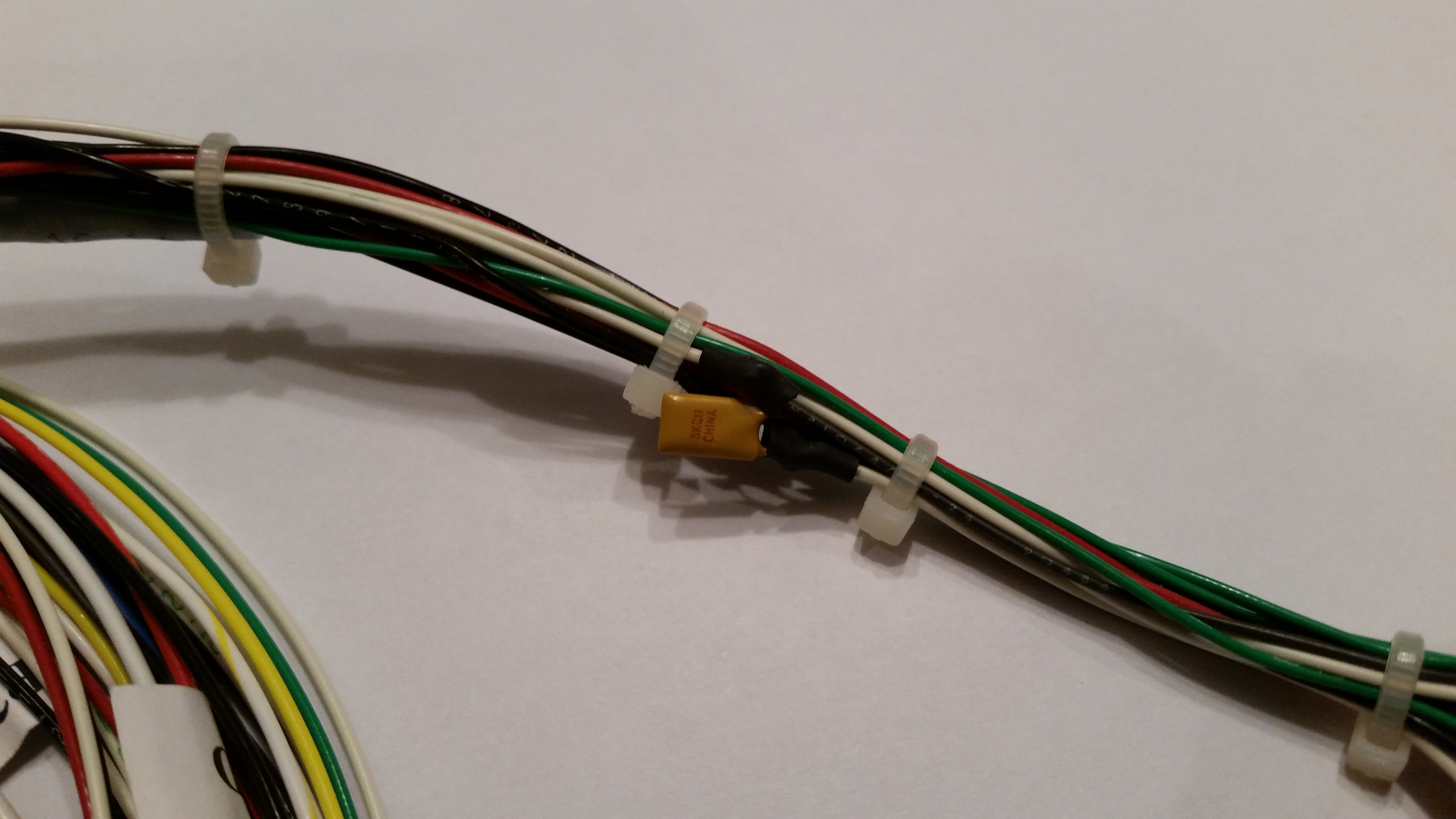
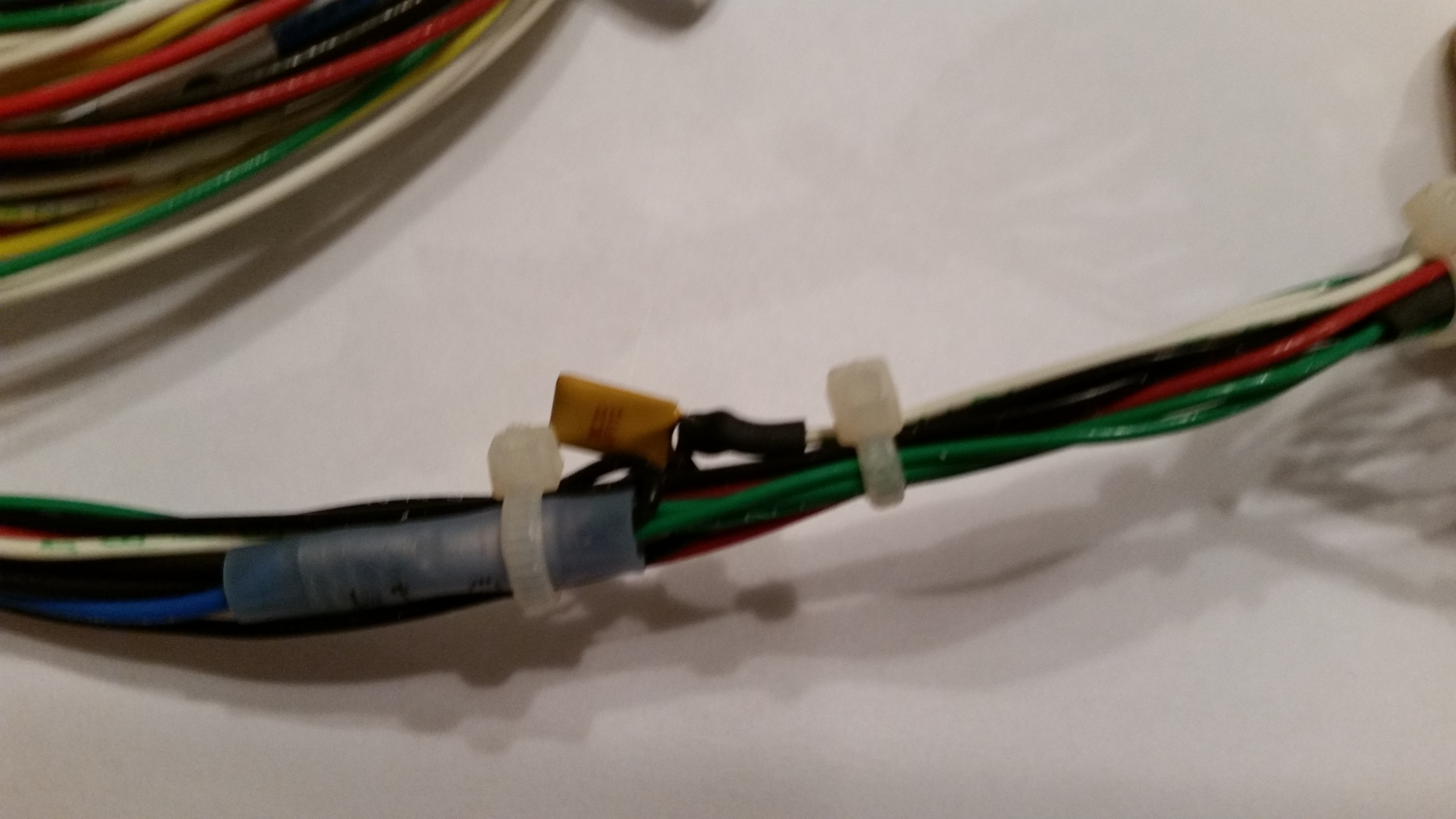
Upon returning home I sat down to fix a design flaw in the Nose Gear Actuator wiring before it became a problem.  There is a small electrical component (diode? capacitor?) that was soldered in the wiring line with one of its two tiny legs soldered to a wire on each side.  If you look at the second pic you can see daylight between the component and the wiring bundle.

Now, my Long-EZ building buddy, Capt Meatballs, pointed this out to me after his broke and he had to find it via troubleshooting.  The connection legs were so fine, that when the one side broke he had to buy an entire new component & solder back into place to fix it.

Electric gear actuator preventive maintenance

Potential for mechanical failure

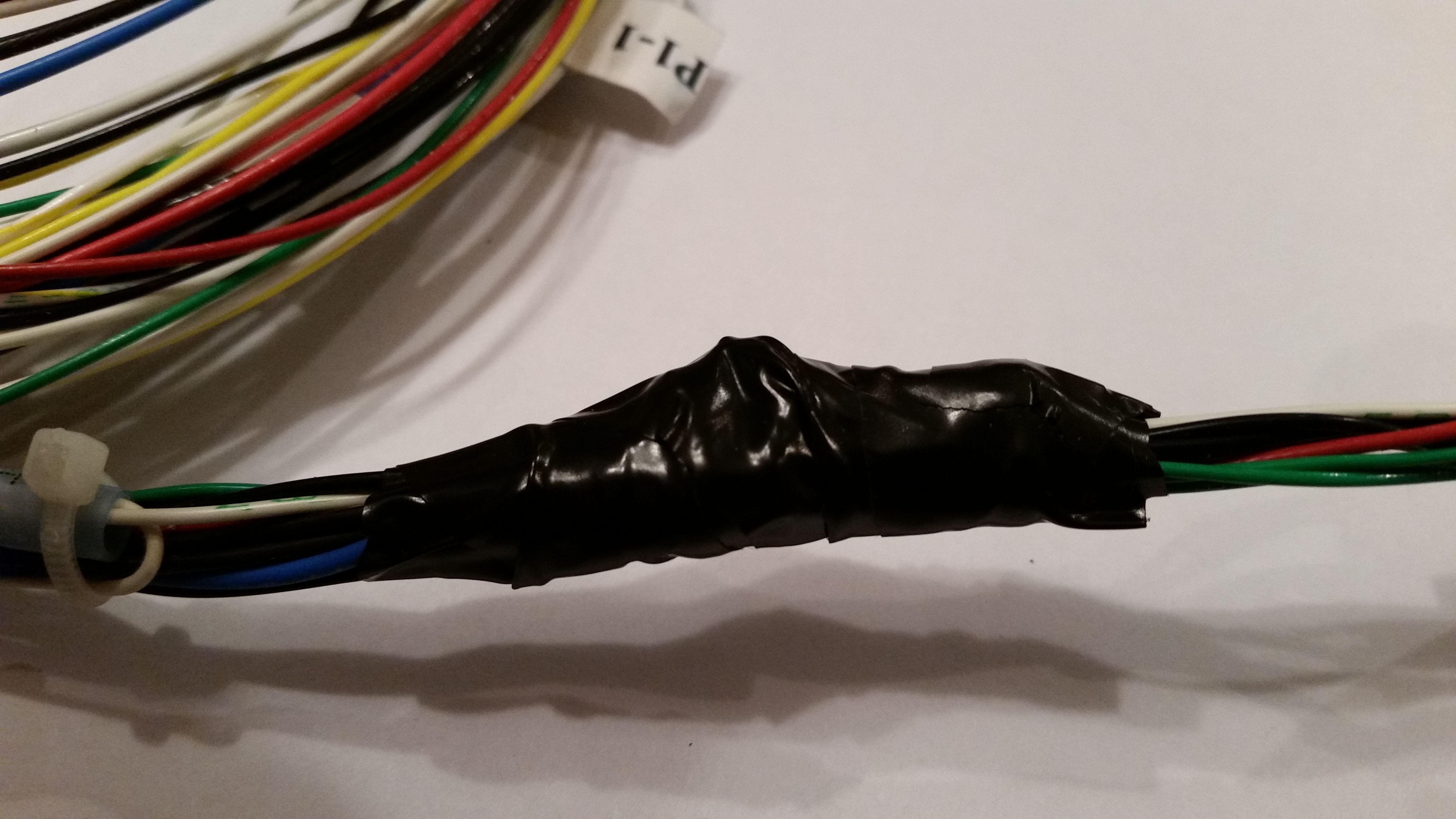
To avoid this issue I employed the “poor man’s electrical potting material” solution to this situation.  I took electrical tape that I had folded over a couple of times and wedged it underneath the suspended wire legs on each side to secure them from any pressure coming through the tape and still snapping off one or both of the legs.  I then wrapped the whole assembly in electrical tape.  May not be the prettiest fix, but with a big clump of relays just down the line I wasn’t able to get some tubing shrink wrap over it.  So this fix will have to suffice!

Poor man's potting material!Poor man's potting material!

Now that I have the base of the fuselage dolly built, I’ll start incorporating it into the build schedule.  Thus, while any part, epoxy, or primer is curing I’ll take a few moments to get this dolly built.  My plan is that when I start in seriously on the nose & nose gear that I’ll have this fuselage dolly underneath the fuselage and ready to go.


Chapter 10 – Securing Canard

Early afternoon I went to Home Depot to pick up some supplies to start the micro finish on the bottom of the canard.

Shortly after I returned home, I met future Long-EZ builder, Sohail, and showed him around my shop, and all the various pieces parts of my Long-EZ project.  Of course what ensued was a long conversation on building Long-EZ’s, canards, and airplanes in general.

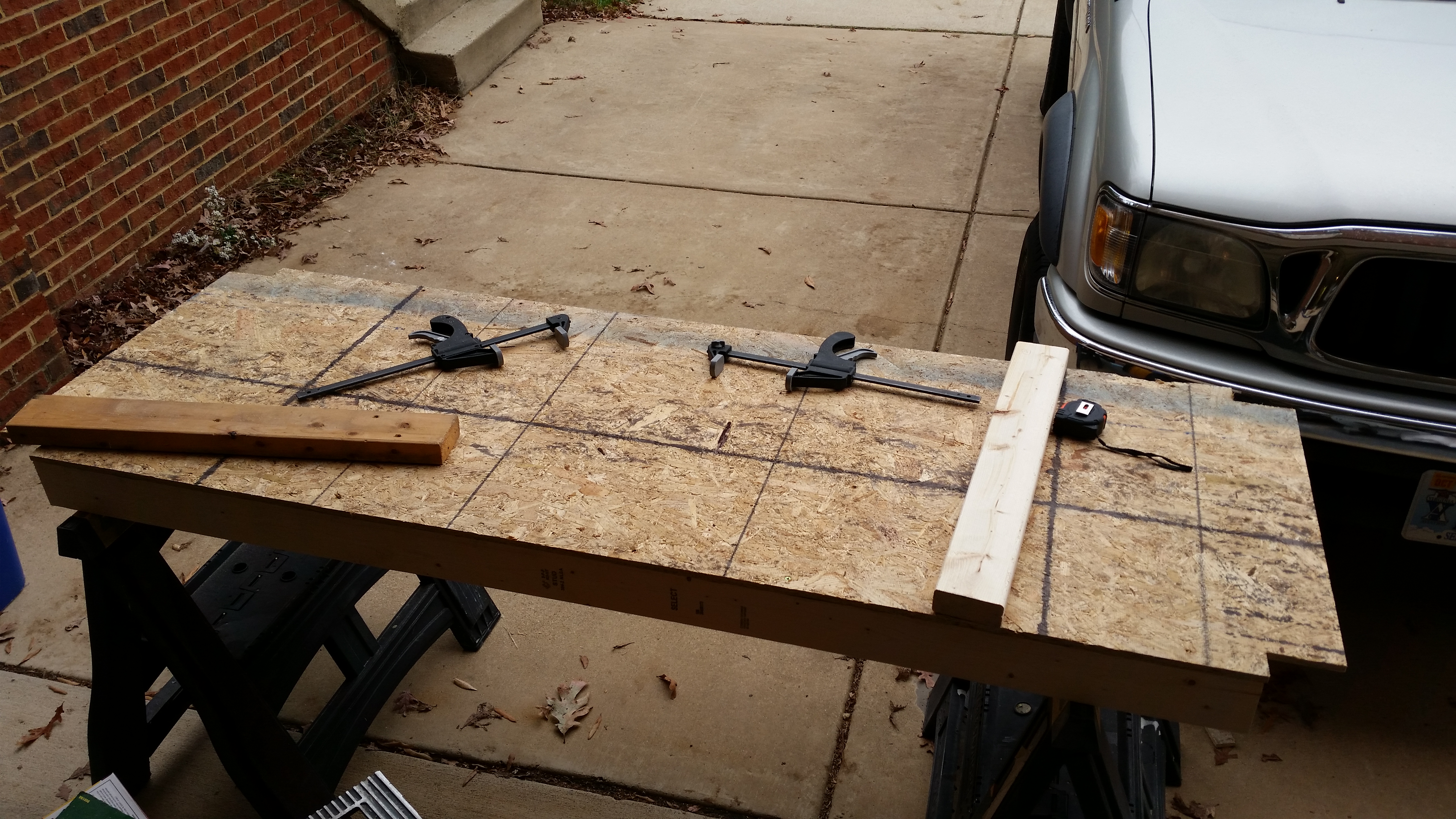
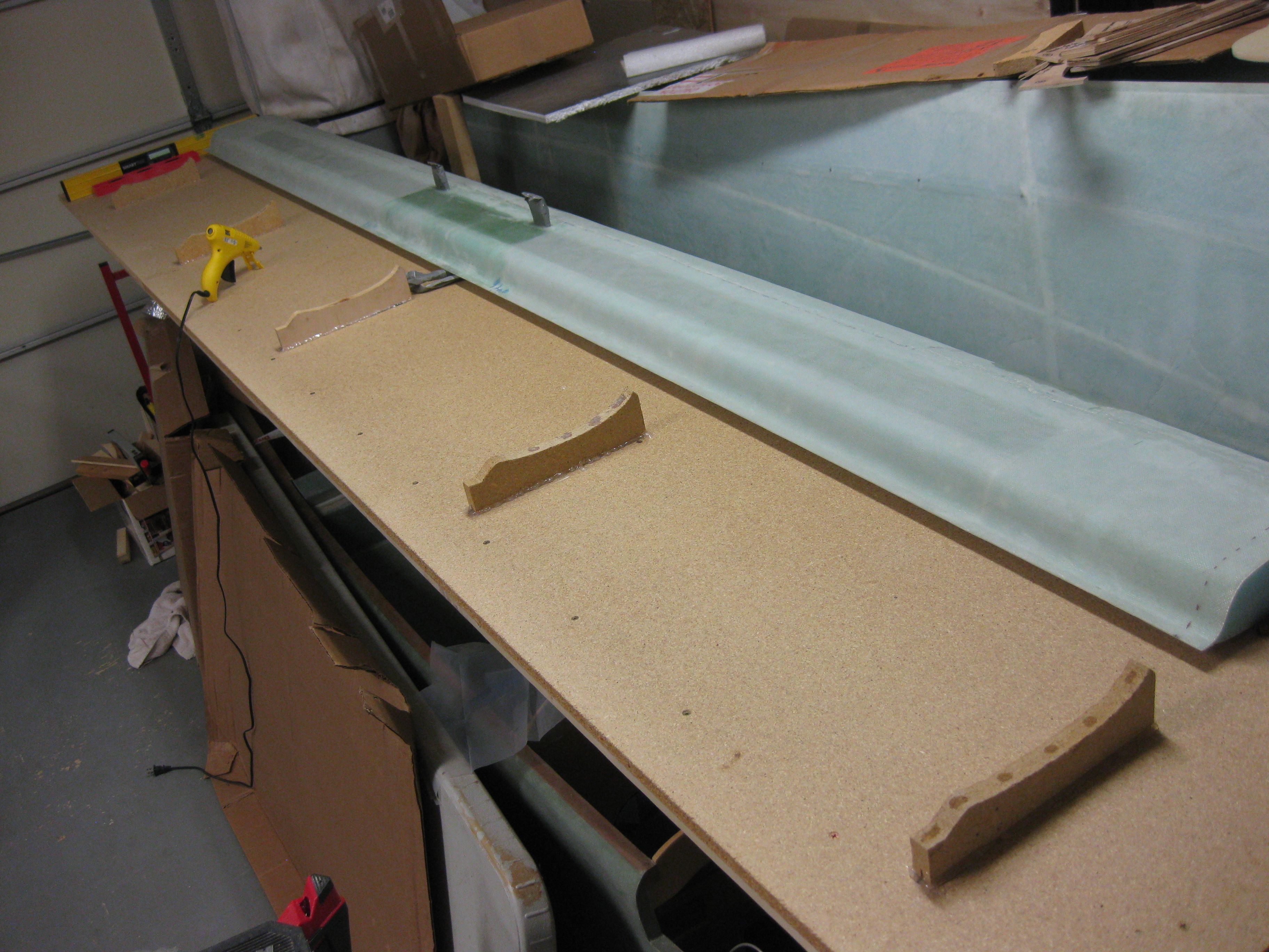
After Sohail left, I worked on getting the canard mounted upside down on the workbench. Thus, my first order of business was to secure the “K” mounts to the workbench surface.

Securing "K" Mounts with Hot Glue

I had thought about either hard-mounting the “K” mounts with screws & maybe some brackets, but I really wanted to minimize the holes in the workbench top.  Plus, all but one of the “K” mounts are made of particle board and I didn’t want to add any stress to them by drilling holes, etc.

Another option was of course bondo, but I didn’t want the mess, the smell or the pain of sanding it off the workbench surface after removing the “K” mounts.  As you can see by the pics, I went the hot glue route.  Hot glue has plenty of strength for the job and it cleans up fairly easily.

After ensuring the “K” mounts were aligned & spaced properly, I hot glued them to the workbench top.

Securing "K" Mounts with Hot Glue

Hopefully tomorrow I’ll get to some micro-finishing!

Chapter 21 – Strake Leading Edge Kit

After getting settled back in from being at Rough River this past weekend, I set about to do a proper inventory of all the strake ribs and fuel tank baffles from the Feather Light Strake Leading Edge Kit that I bought off Nate Mullins back in late 2013 and finally just picked up.

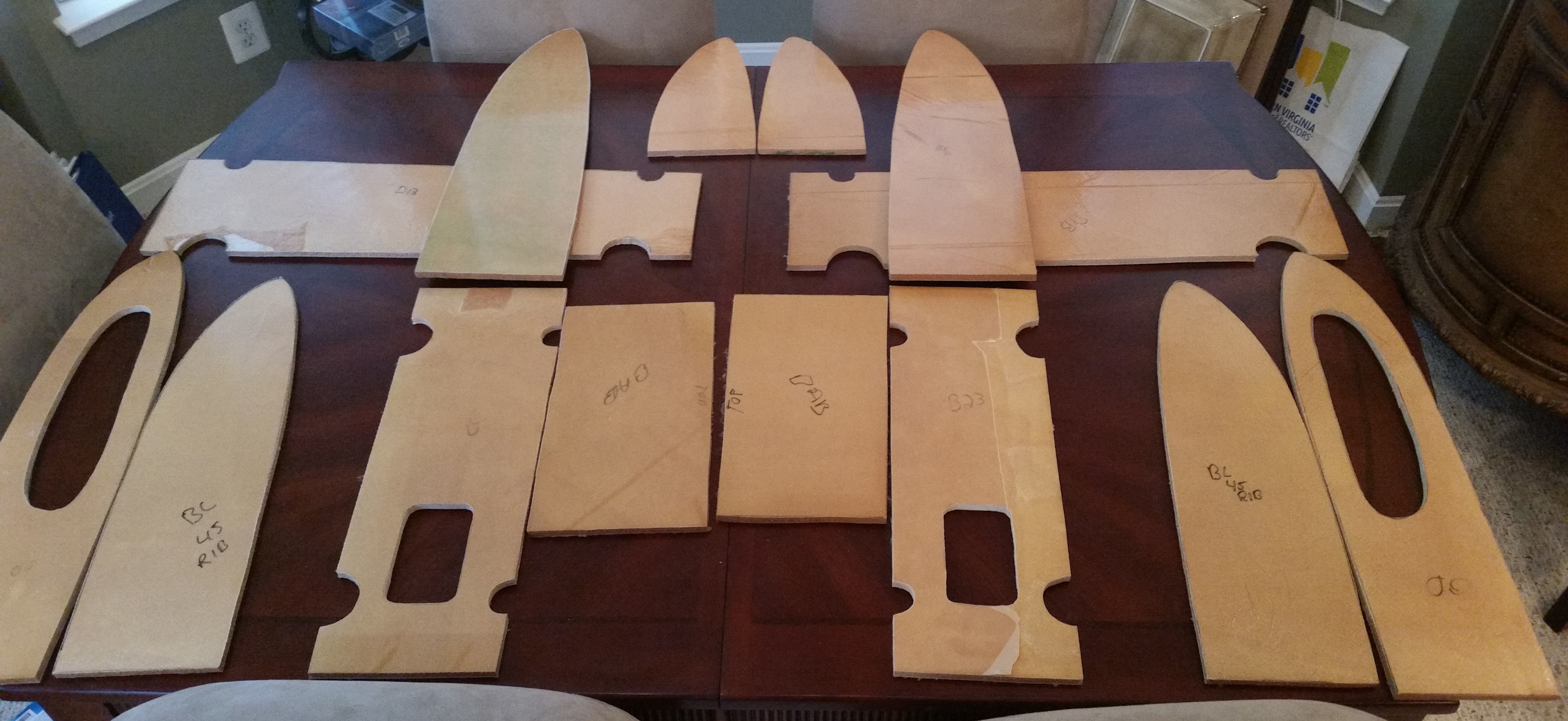
Here’s a shot of them below back AT MY HOUSE! The pieces all have a shiny covering on them which is just an extra layer over the peel ply.  All the parts will need a final trim before final installation, but having these parts pre-glassed and pre-cut should save me days on the strake build.

Feather Light Strake Kit

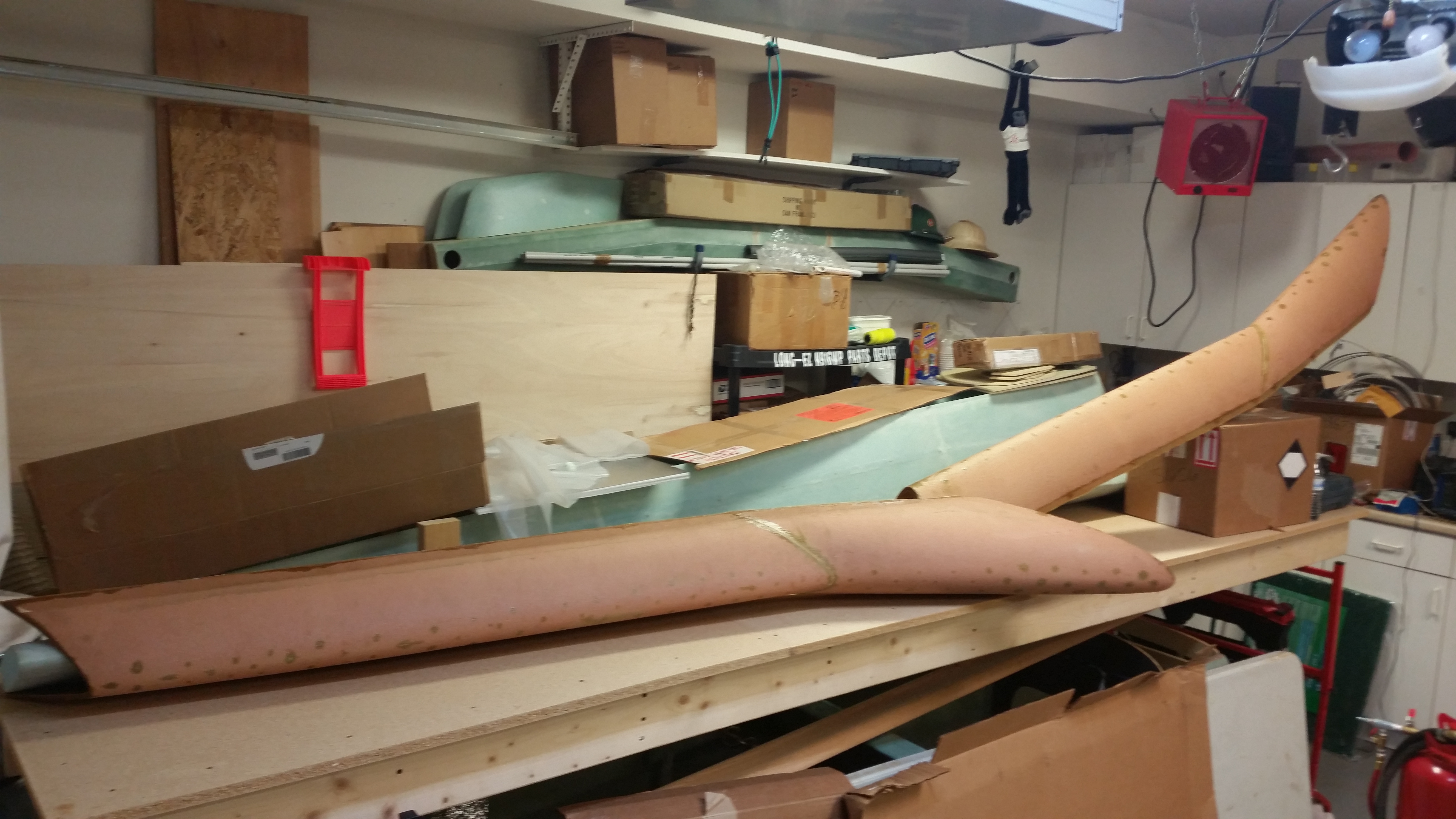
I cleaned up the inside glass of the leading edge pieces, and then set up for a pic before they were  stored away once again.

Feather Light Strake Leading Edges


Chapter 25 – Finishing

Just a quick post to show that over the past few months I’ve been stockpiling various stuff I’ll need for finishing the canard & other parts of this bird.  I know a fair number of builders don’t care for using West for the final finishing, but I don’t have any issue with it & so when it goes on sale I’ll pick up a gallon of it to add to the inventory.

Finishing Stuff

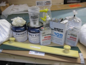
And as you can see by the pics, my initial plan is to use boat paint for the primary finish.  In addition, as per Wayne Hicks’ recommendation I picked up some 3M Hookit Long Boards & sandpaper for the wings and other large areas.

Finishing Stuff

If all goes according to plan, I’ll be putting this stuff to good use when I finish the canard.


Prep, Restock & a little R&D

It’s quite the rainy day in the Nation’s Capitol today.  I took some time this morning to do some research on my sandblaster woes.  I found out some great info, and as often is the case with Harbor Freight equipment there is a hidden set of gotchas that comes with it . . . awesome, cheap prices, but many times at the expense of having to incorporate some type of workaround.

Thus it is with my sandblaster.  Even though I have an air dryer for my compressor, it is old and probably performing far below what it should be.  At some point I’ll get a new desiccant filter for my air dryer, but to get moving quickly on this project, I simply bought an inline desiccant air dryer, along with an inline filter, while I was out buying a myriad of things for the next phase of this build.  I’ll need to track down a few more things like higher end ball valves if I want this sandblaster to perform for a good period of time.  I did hold off on buying any more blasting media until I conform my upgrades work.  One last thing on the sandblaster: I learned that there is a definite trick in the order to which the 4 ball valves get opened, and exactly how far to open each of them to keep the media flowing, and not jamming up in the hose.

I also did some research on paint for the rollover assembly (and possibly the instrument panel).  I want a very nice quality, professional-looking roll bar, but I’m not looking to shoot it with a two-stage polyurethane or anything like that.  Also, because I’m using bondo to clean up the seams I can’t powder coat it, which I wasn’t really looking to do anyway.  I like the idea of having a paint job that looks great, but that I can change the color somewhat easily if I want, and that can easily be reapplied if I need to modify or add something later (like the tab for the pneumatic canopy stay).

Thus, over the last few days I’ve gone into backyard mechanic mode and have been researching rattle can clear coating for the roll bar (Yes, I can here all the groans, gasps & sighs now! HA!).  Again, something that will make it look great, but is also somewhat EZ to maintain.

Now, my thought for the aft roll bar support tubes is that they will serve 2 primary purposes:  1) (rare) buttress the roll bar if the roll bar (God forbid) ever gets called into real action, and 2) (common) used by the GIB as hand grips for ingress/egress of the bird.

With the hand grip piece of the puzzle in mind, I was thrilled when I not only ran across Rustoleum’s FLEXiDip, but that it had it’s own version of clear coat that could shine it up with the rest of the roll bar.  FLEXiDip provides whatever it’s applied to a rubbery surface for gripping.  Sounds perfect for the roll bar support tubes in my mind!

To test it out, I grabbed an old rusted pipe that I use as a cheater bar.
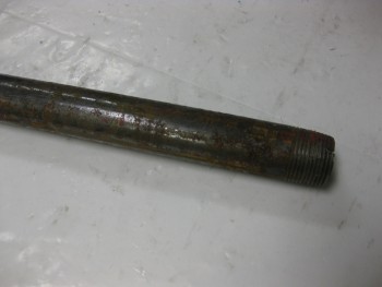
Test pipe

I then hit it with the wire wheel to clean it up for my test shoot.
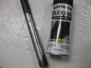
Prepping pipe for test

And I then shot a number of thin coats on it (as per directions).
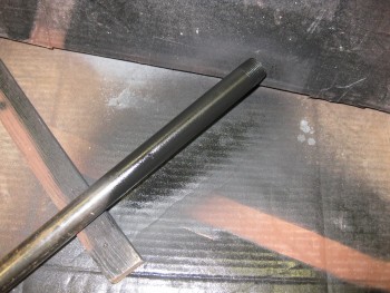
Shooting FLEXiDip

Here’s the FLEXiDip when it’s dried (no clearcoat . . . yet!)
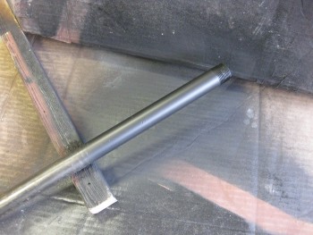
Dried FLEXiDip

And another shot with a bit more contrast to see it better.

BTW, the texture is not a thick rubbery feel, but it’s definitely “softer” than regular paint. Pretty cool.  I also picked up another brand, Plasti Dip, that I’ll be trying out in a head-to-head runoff for the best rubberized coating.
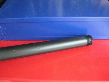
Contrasting the FLEXiDip

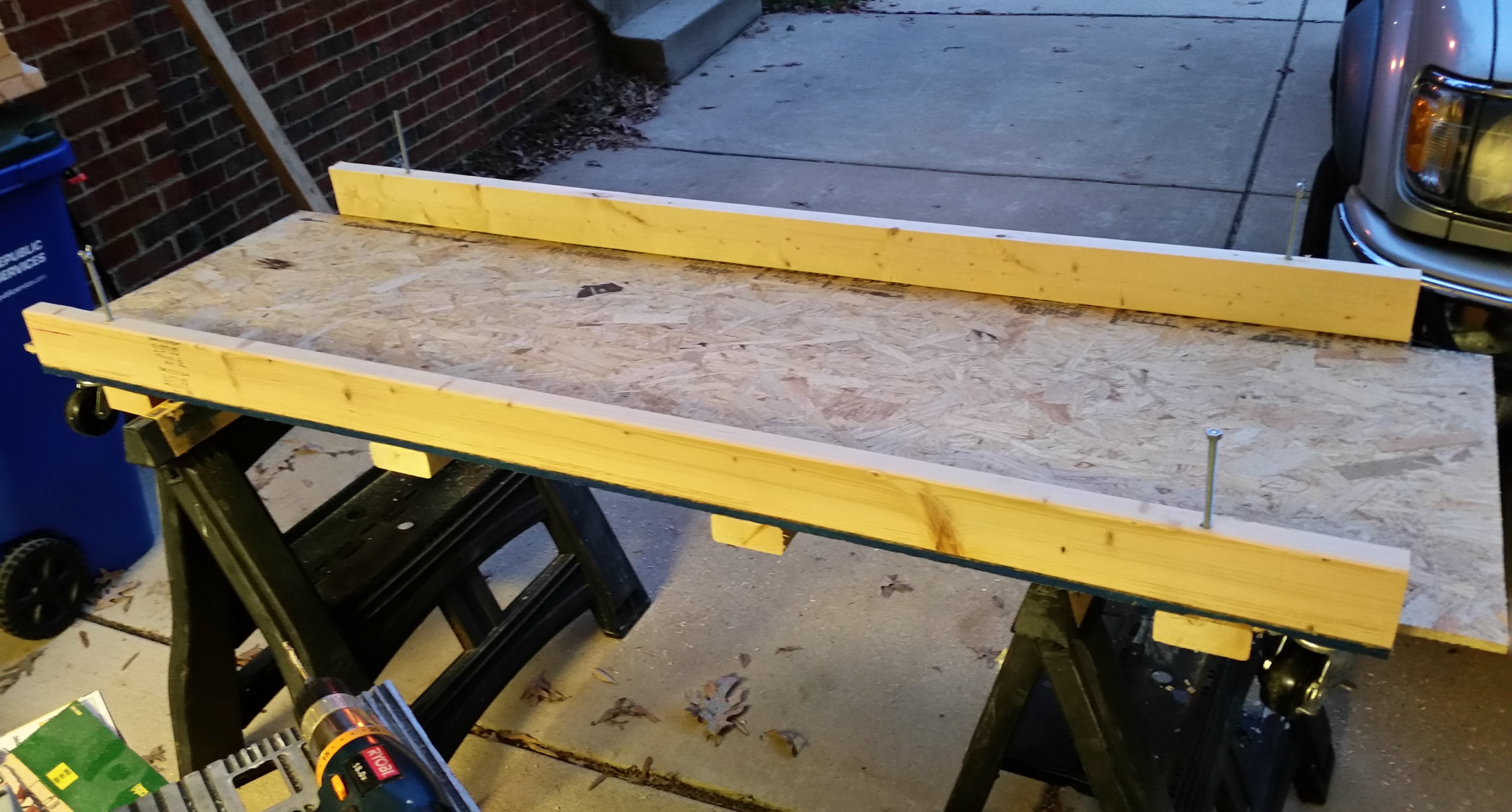
In addition, I bought some 12 ft long 2×6’s to use for the canard work bench that I’ll be building within the next few days.
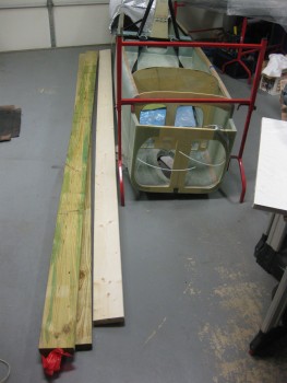
Wood for canard workbench

Finally, as you may get a slight glimpse from the picture above, I spent over 2 hours last night doing nothing but cleaning & organizing the shop and putting all my tools back where they belong.  With that, the start of the finishing of Chapters 10 & 11 looms ever closer!
 

VSWR what?!

In the December 2013 edition of Kitplanes magazine I found yet another useful piece of information, and like so many other times during this build, it came a year or so too late. The article was written by Jim Weir–maker of many canard antennas–and discussed checking the VSWR (Voltage Standing Wave Ratio) of each antenna before burying it under the skin of a plastic airplane such as the Long-EZ, at which point if you have a problem . . . well, better think up some good solutions!

Jim recommended a MFJ-259B Antenna Analyzer to check the VSWR on each antenna to ensure they were good.  Again, my antennas already being installed, I still wanted to check them to A) know if any had a VSWR too high to count as good, and B) pick the best between the COM antennas for COM1, and the best between the NAV antennas for NAV1.  The goal is a VSWR ratio less than 3:1, because anything higher is a lot electrical energy traveling back along the OUTSIDE of your antenna coax cable to the transmitting device (ie, radio), which will drive your available Tx wattage to unacceptably low levels and could damage your transmitter in the process.  In addition, as with so many other units of measurement in the weird & wonderful world of electrons, VSWR readings are logarithmic.  Any increases above a 1.5:1-to-2:1 ratio and things start getting real hairy real quick!

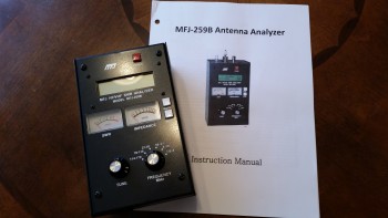
I of course started hunting around for a good, used antenna analyzer at an acceptable price anywhere I could find one.  That pretty much drove me to eBay, where I picked one up for about half the price of a new one.  And thar she be below.

MFJ-259B Antenna Analyzer

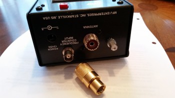
The only problem with my newly won prize (which I actually bought a while ago), was the antenna cable adapter that came with it.  These analyzers can be used for checking any antenna and are common in the HAM radio world, so perhaps the antenna cable adapter that came was used for something even more exotic by a HAM radio bubba.

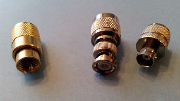
Old Connector ???So although I didn’t know what the mystery adapter was used for, I did know that to check the BNC connectors used on the Long-EZ antenna cables that I would need a BNC adapter for the antenna analyzer.  So, last week I ordered a couple of them, one male and one female, and I got them in today.

New BNC connectors M & F

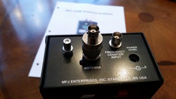
You can see the new BNC antenna cable adapters on the right, and the old one on the left. Below is a shot of one installed on the antenna analyzer.

It fits!

Since the weather is still too cold to economically heat my workshop for glassing, I plan on terminating all my antenna cables with BNC connectors and then checking the VSWR of each one with this MFJ-259B antenna analyzer.

It’s all about safety kids!

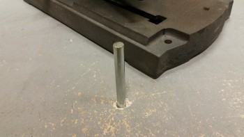
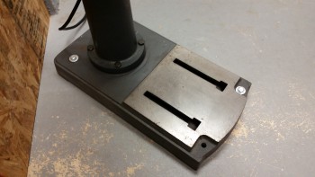
Just a few quick photos of my efforts tonight in installing a couple of concrete anchors to keep my drill press securely mounted to the shop floor.  That’s a tall, heavy piece of machinery that sits on a busy corner of my shop.  Plus, by using the drill press table as my mounting location for the bench grinder, I definitely want to make sure that all is secured from an inopportune, destructive and possibly very painful toppling.

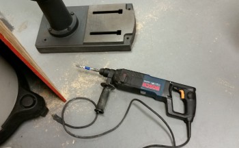
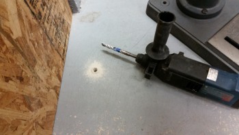
I simply pulled out my Bosch mini-jack hammer and within about 10-15 seconds on each hole had the requisite depth.  That hammer drill literally drills into concrete as well as an 18V drill into soft pine!

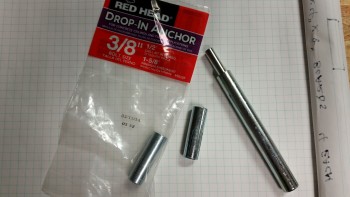
Drill Press Safety BoltsMondo Hole Drilling!Once the holes were drilled and vacuumed clean, I grabbed my two anchors and the installing jack and started pounding away.

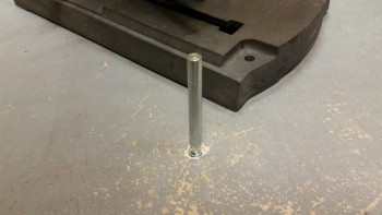
Concrete Bolt AnchorsBolt Anchor TapBolt Anchor SetAfter the anchors were securely in place, the hardest part was aligning holes in the drill’s base over the embedded anchors.  Below is the final product.

Drill Press Anchored!

Back to it … baby steps!

Sorry, but I don’t have any pics to load just yet, but I quickly knocked out a few items on my list that I thought were important to complete in order to establish some data points:

#1 – Elevator weigh-in.  As Canardians and canard builders know, elevator weight and balance is critical.  I established a baseline weight for both my elevators since when I followed the plans method of glassing them, the heat of the curing bondo used to hold the bottom of the elevators in place caused glass-foam delaminations exactly where each blob of bondo was placed.  There’s a great work-around using aluminum duct tape that’s spelled out in a CSA newsletter, but unfortunately the issue with that helpful tidbit came out well AFTER I built my elevators. Besides getting a general idea of each elevator’s weight, the baseline will let me know how much epoxy weight was added after I inject each delam area with epoxy.  If too heavy, I may end up having to rebuild new elevators.

#2 – Fuselage straight & true.  Another issue I wanted to get the skinny on was exactly how straight and true my fuselage is, since I know that I didn’t get it exactly right when I glassed the bulkheads into the fuselage sides.  I still  have to diagram it all out, but although not ecstatic that it was off to any degree, I was relieved to find out that no measurements were off by more than a 1/10th of an inch.  Not great, but definitely workable.

#3 – Landing & Taxi Light Test.  I also grabbed my LED landing and taxi lights, and quickly connected them up to a 12V battery to ensure that they all worked, first off, and to also get a good idea of the light strength and beam pattern of each respective light.  I have to say that I was quite impressed with the lights and I will definitely move forward with my designed electrical plan for the landing and taxi lights.

Final Shop Prep – Part Deux

. . . RISE OF THE MACHINES!!!

You can’t be totally prepared unless your MACHINES are online & ready to go!

My initial objectives starting back on the Long-EZ build is that now that I have my project physically located in one place, I will go back and finish those chapters that I left hanging for various reasons.  For example, chapter 8 of the original plans is where the trademark triangular foam/fiberglass rollover assembly is constructed.  However, since I’ll be employing a metal rollover assembly, it took me a while (actually while I was in Tampa, FL) to design it and to figure out what material I was going to use.  And although I’ve done a fair amount of MIG & stick welding, I of course needed to get trained on TIG welding since I had finally decided that the rollover would be constructed of 4130 steel.  Although I posted this previously, I attended a local welding course in Tampa and the EAA’s TIG welding workshop in Georgia.

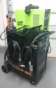
As far as equipment goes, the TIG welder needed to be assembled and checked out. Since I added 220v power to the garage for a heater, I changed the welder plug-in side of my HEAVY duty 220v extension cord to a plug that matches my MIG welder.  I then also changed out the plug on my TIG welder to match the plug on my MIG welder, thus both 220v welders can be used with the same extension cord.  I also have an old Lincoln “Buzz-Box” Tombstone welder, but with my change in plugs it won’t be usable for the time being.  With the swap-out of the plug on the TIG welder, and a couple nit-noy issues with the Argon line filter, it’s now all hooked up & raring to go!

TIG Welder

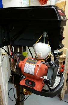
This evening I also finished cleaning up and oiling the drill press, literally knocking some of the rust off of it.  Once I got the drill press good to go, I turned my sights on the bench grinder (I picked it up cheap from Harbor Freight) which I will use primarily for sharpening the tungsten electrodes for TIG welding.  As I was hunting around for a place to mount the bench grinder, I figured that two of the things that I really don’t use that often in building this Long-EZ is the drill press & bench grinder, so why not use that space for a dual purpose and mount the bench grinder to the drill press table and save some space!

And so I did!

Bench Grinder

After finishing the drill press & bench grinder, I spent another hour or so simply cleaning off a bunch of my tools and gear that had years of dust and grit on them.

Thus, from here on out, besides work, flying and my Instrument Training course, any spare time I have I will be putting towards getting this bird finished!