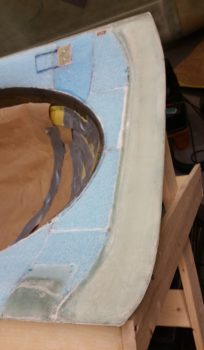
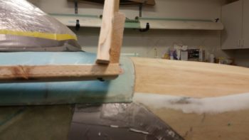
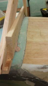
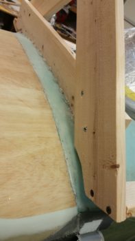
Fuselage in NC!

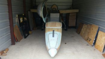
This morning I finally got around to getting over to the storage unit to put the bird in its new cage for awhile: a 10’x20′ storage unit.

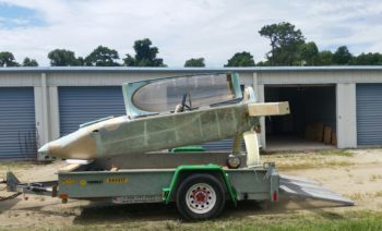
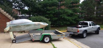
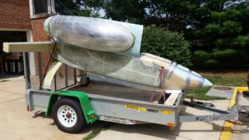
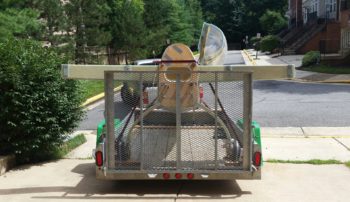
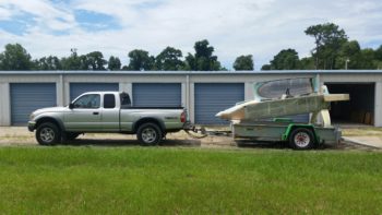
One last trailer shot before I unloaded the fuselage.  I have to say I’m loving the canopy. The fit and geometry is still spot on and it’s simply a treat to open & close the canopy…. and moreover to have a canopy mounted to open & close!!

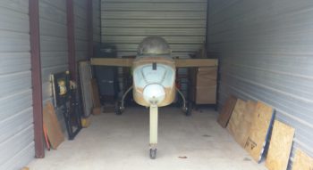
Since the front rollup doorframe of the storage unit is a few inches narrower than the CS spar width I had to do some angling machinations to get the fuselage into the unit, but it still went in without too much effort.

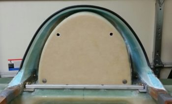
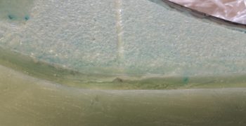
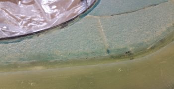
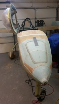
Having not seen my nose or canopy with the bird in the grazing position, I wanted to get a wide angle grazing shot.

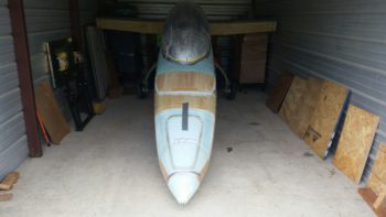
And a closer grazing shot….

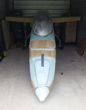
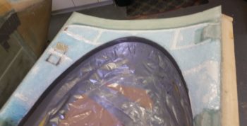
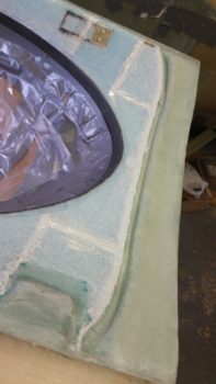
And finally a grazing shot with the canopy open.

I have to say it’s a relief to have the fuselage safely down in NC without any incident. Sadly, from here on out over the next month or so my build postings will be fewer and farther apart until I’m relocated down here in NC.


Fuselage on Trailer!

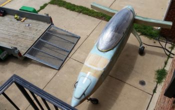
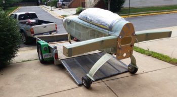
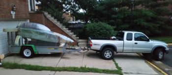
Today was about loading up the fuselage on the trailer to haul it down to NC.

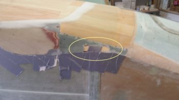
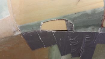
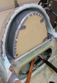
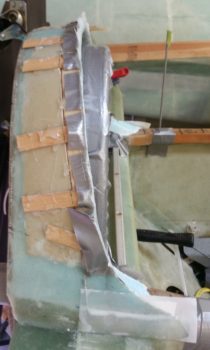
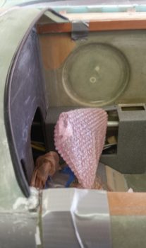
I started out by using the Fein saw to cut a notch on each side of the aft nose cover about midpoint where the openings for the canard will be located.  I then spent a few minutes digging out the foam to create a channel from one side to the other.  This channel will be used for transiting tie-downs through the nose.

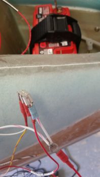
I then spent a bit of time reconnecting the wiring (with the requisite bit of troubleshooting) for the nose gear system.

I then got to work rolling the fuselage out of the shop and positioning it into place for loading it onto the trailer.

I then wheeled the fuselage into position just on the edge of the trailer ramp, with all 3 wheels positioned so that the fuselage was on the trailer CL.

I then rolled the fuselage up into the trailer and secured it into place.

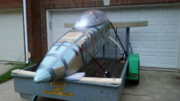
A few hours and one rainstorm later, I had the fuselage and canopy ready to roll!

With duct tape in all the right positions, I was ready to head off on my trek down to NC.

I’ll be down in NC over the weekend delivering the fuselage to its new home.  When I return my primary focus will be on the house to get it prepped to sell!


Chapter 18 – Canopy completed!

First off, I started off today by taking pics of both the front and aft intersection of the canopy to show how the intersections worked with the seals mounted on the flanged edge underneath.  Overall, I’m really happy with the intersections thus far.
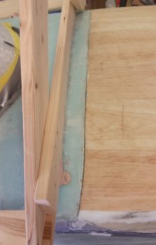
I then got busy getting the canopy cross brace installed.  I started by measuring and marking the sidewalls at the canopy cross brace position.

I then set the piece of 1/4″ Finnish Birch plywood (same stuff we use for the firewall) in place and took some notes on how it needed to be shaped.  I then shaped each end in prep for installing it into the canopy frame.
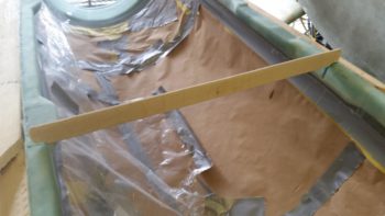
I also drilled a couple of holes on each end for the cross brace to better grip the flox that it would get embedded into.
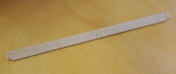
After making the slots in the canopy side rails with the Fein saw, I then test fitted the cross brace piece into the canopy frame.
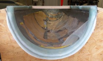
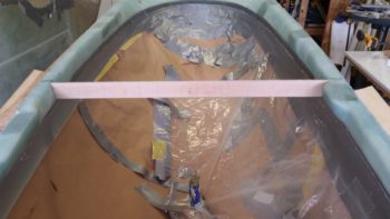
After verifying the fit into the canopy frame, I then slathered a bunch of epoxy into each side rail slot and installed the cross brace.
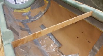
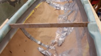
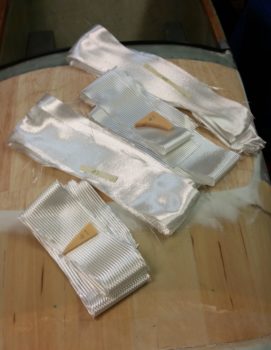
I first covered each side with a ply of UNI that overlapped onto each side canopy rail about 1″.  I then wrapped the cross brace itself with a prepregged 2-ply BID layup twice, so that the end result was 4 plies of BID on both the front & aft side of the cross brace.  Finally, since the 4 ply layup in the middle didn’t overlay up onto the side rails, I then laid up 2-ply BID tapes in the corners that overlapped an inch onto the cross brace and the side rail. I then peel plied the layups.
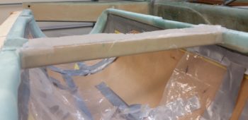
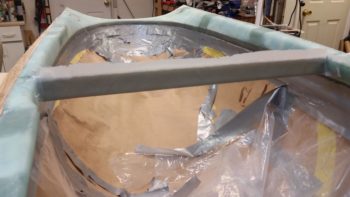
Another wider angle shot of the glassed canopy cross brace.
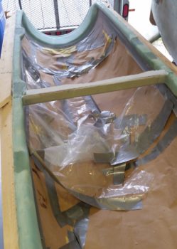
With the cross brace layups curing, I then got to work on hinges.  After an hour of finagling the angles and trying to fit the proverbial square peg into a round hole –and conferring with both Mike Beasley and Nick Ugolini– I pulled the trigger and set the hinges in place.

Here’s the aft hinge getting the holes drilled for mounting.
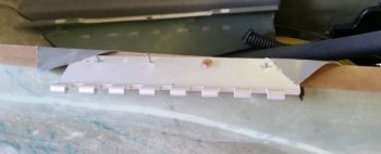
Now, when I mounted the aft hinge I actually screwed up during my drilling ops that apparently pulled the front side of the aft hinge inboard by about 1/16″.  Instead of ripping out or messing around with repairing the geometry of the aft hinge, I set about to see if I could mend my mistake by setting the forward hinge inboard just a bit…  I did, although it was a bit further inboard than I would have chosen, but I compared it to one of the original hinges and my pivot point was still outboard of the longeron line . . . barely!
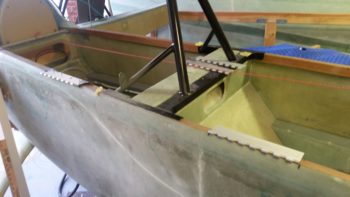
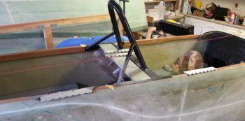
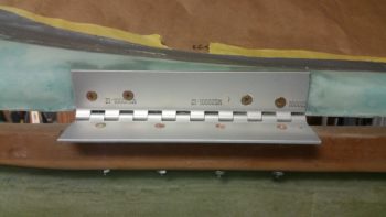
In the end my mistake worked serendipitously to pull the forward hinge in just a bit and lesson the issue I was having placing both hinges on the longeron equidistant from the CL. As it was, I was able to get the hinges lined up to each other (the front of the aft hinge is still maybe 1/64″ off) and, moreover, by pulling in the front hinge a bit I minimized the disparate difference from CL between the 2 hinges to just about 1/4″.  Below we have the lower hinges mounted in both an open and closed state.
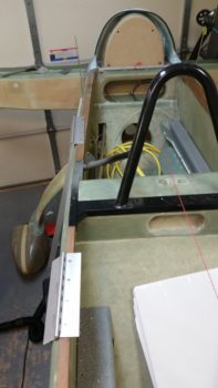
I had to run down to Home Depot before they closed, so before I left I slathered a few dabs of bonbo onto each hinge and then set the canopy frame in place atop the fuselage.
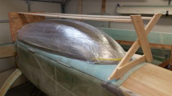
Upon returning from my quick outing, I opened up the canopy from the fuselage for the first time via the hinges!  Before clamping and setting a screw in the vertical canopy support board, I cycled the canopy open and closed a number of times.  Besides a very slight rubbing on the turtleback flange with the aft canopy, the intersections and hinge geometry seriously looked spot on!
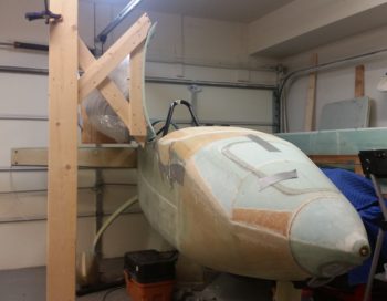
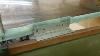
So I then got busy drilling the screw holes in the hinges and countersinking the holes.
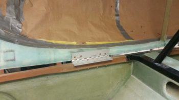
With the geometry and sheer size of my canopy, it really made me have to mount the aft hinge much farther outboard than I had planned, at a much more distinct angle as well.
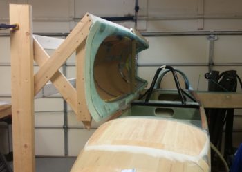
With the holes all drilled for the canopy bolts and the cross brace cured for a considerable number of hours, I then removed the wood support frame from around the canopy.
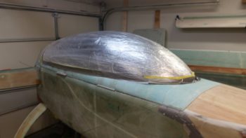
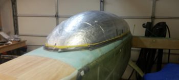
After a couple of trial runs I dialed in the open position of the canopy to set and drill the canopy gas strut attach bracket to the cross brace.
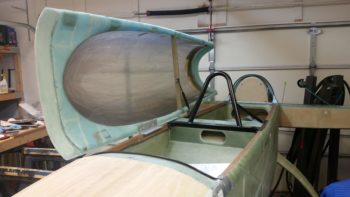
Here are some closer shots of the mounted canopy gas strut.
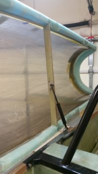
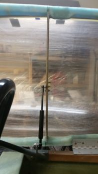
A good shot of the angle of the open canopy.
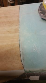
Finally, with the canopy mounted to the fuselage via hinges, I wanted to show once again how the front and aft intersections looked.  Again, these pics are with the seal trim mounted under the transition flanges.
With the canopy virtually complete –except for the latch hardware– tomorrow is all about getting the fuselage loaded up onto the trailer I’ve had sitting in my driveway the past few days and getting it moved down to NC!



Chapter 18 – Canopy frame glassed!
I started off today by pulling the peel ply off the aft canopy layup.  I then cleaned up the layup and cut off the overhanging glass.

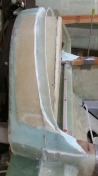
Here’s a shot of the just-glassed aft internal canopy frame.

And a shot of the entire canopy frame so far . . .

I then spent a good hour sanding down the groove on the aft side of the canopy, as well as both the aft canopy edge and the front turtleback edge, to accept the turtleback flange and trim seal.  This of course involved countless cycles of taking the canopy off and putting it back on the fuselage.  I finally got it dialed in and the pic below shows the canopy in place with the trim seal in place underneath the canopy (again).  The significance of this iteration is that now the surface of the aft canopy is glassed.

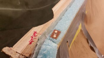
I then made up another K1000-6 nutplate assembly to place in the aft left corner of the canopy to mount a spacer that will keep the compression on the canopy seal correct. After finishing the nutplate I then carved out the location that it would go in the canopy frame and set it in place.

Again, after about 4 hours total I finally finished glassing the left side of the canopy frame! Obviously this means that the entire canopy frame is glassed!!
Here are a couple closer shots of the just-glassed left side canopy frame.  The top pic shows the aft left canopy frame while the bottom pic shows the forward left canopy frame.

Before I started glassing the canopy I had laid up 1 ply of BID into the channel between the turtleback front edge (which also got glassed coincidently) and on top of the existing flange.  This ply of BID will help secure the cantilevered flange from the top side.

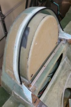
I then of course had to check it out with the black trim in place.

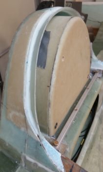
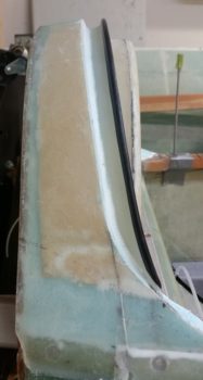
And a shot that shows the profile view of the turtleback/canopy flange and the black trim.

Tomorrow my goal is to get the canopy hinges and gas strut mounted in place so the canopy will be ready to travel.  Of course, to do the gas strut I’ll have to glass in the canopy cross brace . . . which I intend to do fairly early tomorrow.


Chapter 18 – Aft canopy glassed

No, not the aft canopy as in I have two canopies…. a fore and aft canopy! I mean the canopy’s aft frame was glassed!  Ok, more on that later . . .

After running around doing some prep for my fuselage haul down to NC and picking up the trailer, my first shop task was to mark and trim the cured glass that makes up the turtleback seal flange.

[Note: I decided to wait on loading up the fuselage until I finish the canopy, so while fellow LEZ bubba Mike’s visit was great, it turned into a more of a social one since I really do need (or want!) to have the canopy installed before hauling the fuselage down to NC. Since I have the trailer for a week, another day or two to get out the door won’t hurt...].

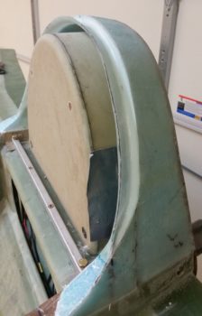
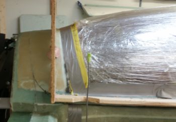
Here we have the numerous popsicle sticks with copious amounts of hot glue to keep them and the foam form pieces in place.  Also you can somewhat see the trimmed turtleback seal flange.

I then removed all the dried hot glue, popsicle sticks and foam & tape form pieces.  I then pulled the peel ply from the top/inside of the seal flange and cleaned up the glass.

Here’s another shot of the turtleback’s new addition from the left side . . .

I then test fit a piece of the same black rubber trim that I’m also using on the glare shield edge.  The trim here fit well and I’m good with using it for the seal trim back here.

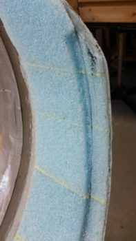
To configure the aft interior end of the canopy to interface with all this that’s going on at the turtleback, I used some model paint to create a black edge on the seal flange.  I then quickly mounted the canopy and pressed the canopy’s blue foam into the flange on the turtleback . . .

The result was both a black mark left by the seal flange’s painted edge, and a depression in the foam.

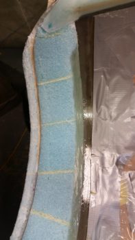
It took a couple of iterations to shape the canopy’s aft foam and dial in the interfacing aft canopy and turtleback, but it looked good and I was satisfied enough to start glassing the aft canopy frame.

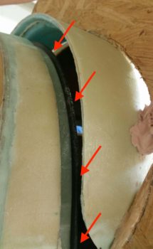
The pic above was taken with the black rubber trim (red arrows below) in place, at which point I then knew that the trim would fit underneath the aft canopy edge.

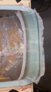
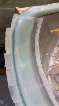
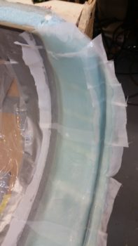
I then got to work glassing the canopy’s aft edge, side #3 of 4 sides.  If you look closely in the pics below, you can see just aft of the canopy edge is a greenish line about 5/8″ in width that tapers back into the canopy for a termination point at each outboard end.  That line is a 3″ UNI tape that I essentially pulled apart and made 4 separate 5/8″ wide plies stacked one on top of the other, with each respective/successive ply wet out as it was placed in this “mini-trough.”  This will make a solid fiberglass bow connected to and just aft of the canopy edge.  I then laid up a “normal” 3″ UNI tape that covered this stacked tape with the remaining tape glass positioned aft of the stacked 3″ UNI tape.

I’d like to reiterate that these extra 3″ UNI tape plies serve a twofold purpose:

  1. It reinforces the aft canopy to serve as an ad hoc roll bar for the GIB, and
  2. serves a vital role in keeping the aft canopy shape since I will have no cross structure (arrow stock) across the very aft canopy.

After the requisite minimum canopy layup work time of 3 hours, I finally finished glassing the very aft of the canopy frame.  I then of course peel plied it.

Here are the 2 sides of the aft canopy frame, glassed and peel plied.

Tomorrow I plan on finalizing the canopy construction by laying up the last round of glass on the frame: the left side.  I will then prep as much as possible in order to get the canopy mounted to the fuselage via the hinges.


Chapter 18 – Canopy rail glassed

Today I started out by spending a good hour cleaning the internal turtleback 1-ply BID layup.  I pulled the peel ply and dealt with the peel ply boogers.  I also razor trimmed the glass . . . one nice thing about a 1-ply BID layup is that it doesn’t matter if the glass is cured or not, it’s EZ to razor trim!

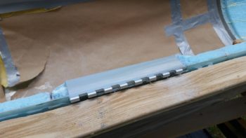
I then got busy cutting up and shaping some scrap urethane foam to attach to the front edge of the turtleback, using both nails and hot glued popsicle sticks.  I then sanded the interior edge of the urethane foam even with the interior surface of the turtleback.

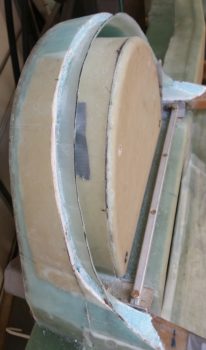
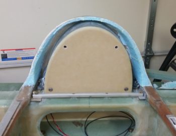
Here you can see the shaped urethane foam pieces held in place with nails and hot glued popsicle sticks.  After I was certain that the foam was mounted fairly securely, I did a final shaping that included rounding over the bottom forward corner with about a 1/4″ radius.

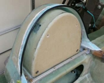
I then taped up just the bottom edge of the foam.  This foam form is to create a lip akin to the what the glare shield up front has, and that will stop any water from leaking into the cabin.  Moreover, it will also be used as a flange for the canopy seal to seat into.

I then prepregged and laid up a 3-ply BID layup around the taped foam form, overlapping onto the interior turtleback glass by about an inch.

Here we have another couple shots of the 3-ply BID layup that will make up a flanged lip around the turtleback for the canopy to seat into.  As you may be able to tell, I peel plied both the tape form before laying up the 3 plies of BID, and then peel plied on the outer surface of the 3-ply layup.  This is to allow for me to pull the peel ply on the top of the flange and layup a ply of BID to both close out the front edge of the turtleback, but to then connect that to the lip flange, adding another securing ply from the top side.

While the turtleback seal layup cured, I then made up another #6 screw nutplate assembly to mount another 1/16″ thick aluminum plate to on the bottom edge of the aft canopy rail. I will then flox an associated 1/16″ thick plate onto the longeron top so that the two plates come in contact and rest against each other when the canopy is closed.  These plates will ensure a 1/8″ gap to allow for proper compression of the rubber canopy seal.

I then got busy cutting the UNI and BID required as per plans for the right side canopy frame rail layup.

I then spent the next 3.5 hours glassing and peel plying the right side canopy frame rail.

Here’s another shot from the aft end of the right side canopy frame rail layup.

I also measured and cut the 3 plies of BID for the aft canopy frame layup that I will definitely try to squeeze in tomorrow.

Tomorrow fellow Long-EZ builder Mike Monsivaiz is coming over to help me load up the fuselage to haul it down to NC.  Although I will have the fuselage on the trailer ready to haul down to NC, I may delay one day to finish up the canopy to the point I can mount it properly with the hinges and gas strut…. that way the fuselage can have the canopy mounted atop it –sans the frame!– as it travels down to NC.  Time is TIGHT, but we’ll make it work!


Chapter 18 – Turtleback glassed

My goal for the day was to get both the turtleback interior glassed (which happened) and the aft canopy frame glassed (which didn’t happen).  I didn’t glass the internal aft canopy frame due to a twofold reason: 1) I need the drip seal on the turtleback to be shaped first, and moreover, 2) there was just not enough hours in the day to get it all done!

I started off today by cutting the set of canopy hinges from the 2 x12″ stock I had on hand.

Although my hinges are much larger than plans (MS20001-12) –which I was clued in on by two of my fellow builders: Dave Berenholtz & Mike Beasley– I still cut them to the plan’s length of 8 inches.

I then test fitted a hinge on the front hinge hardpoint depression.

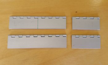
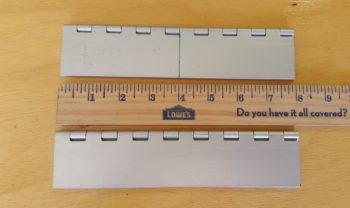
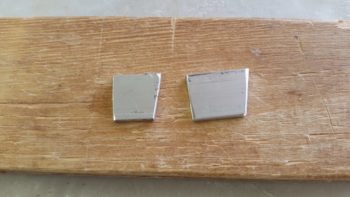
While I had my chop saw out to cut my hinges, I went ahead and lopped off the angled ends of my 1/8″ thick aluminum bars to make up 4 spacers to place at the front and aft end of each longeron.  For now these little spacer nubs will mimic the 1/16″ spacers that will be mounted to both the longerons and the canopy frame, both front and back, that provide the proper gap for seal compression.

Here are 2 of the 1/8″ thick spacer nubs I cut . . .

And here are a pair of spacer nubs taped in place at the front end of the longerons.

And a couple more 1/8″ thick spacer nubs at the back end of the longerons.  This allows me to get rid of the long spacer bars that I used as the original 1/8″ spacers when constructing the canopy frame and up until today that I was using to maintain that gap whenever I placed the canopy on the fuselage.

After covering a good portion of my shop in fiberglass dust from Dremelling out the front canopy hinge depression last night, I decided for the rest of my messy massive dust-producing canopy frame work that I would haul the canopy out to the side yard…. so that’s what I did!

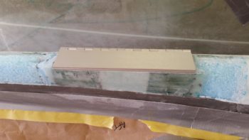
I then got to work on the canopy aft hinge depression.  Again, I’m making these hinge depressions about 0.140″ deep since the hinges measure 0.270″ at the midpoint when closed.  With the top hinge half buried 0.140″ into the canopy frame, this clearly leaves 0.130″ [very close to 1/8″] left for the other hinge half, and as a close-to-1/8″-spacer for the canopy seal.

After creating the aft canopy hinge depression I test fitted the canopy hinge.  Looks pretty good so far!

With the canopy outside I decided to knock out cleaning up the aft canopy frame foam and original layup to allow for a glass to glass joint back here . . . what I’m going to do is a bit detailed, so I’ll explain it when I do it.  The main thing here is that I got the canopy’s aft frame shaped and ready for glass.

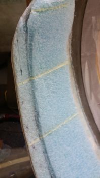
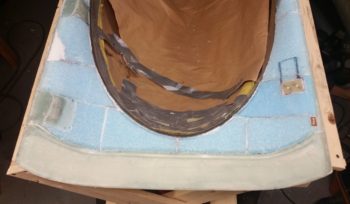
Here’s some closer up shots of the canopy’s aft frame ready for glass.  The narrowed foam on the aft end is for the same type of seal that I’ll use along the canopy frame sides.

Again, before I can glass the aft canopy frame, I needed to get the interior turtleback glassed.  I spent a bit of time finishing up getting all the dead micro removed from the front face of the firewall… due to a fair bit micro oozing onto the firewall when I set the foam blocks in place to create the turtleback.

After I cleaned up the firewall, I did a final shaping of the foam to get it locked in to the right dimensions.

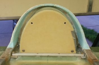
The first step in glassing the internal turtleback really had nothing to do with the existing turtleback proper, but rather the additions of the 2 pieces that I lopped off of the aft lower corners of the canopy frame.  As a reminder, this is to ensure clearance with the forward-projecting conical shaped “shoulders” that extend from the upper cowling.

I micro’d the foam and hit the glass to glass edges with a bit of flox. I then used some finishing nails to secure both sides in their respective places.

Here’s a shot of the interior turtleback additions.  I didn’t trim the additions at this point because I wanted to do it with them mounted in place.

A little while later the turtleback additions were cured enough that I could proceed with laying up the 1 ply of BID that goes on the inside surface of the turtleback and overlaps onto the front face of the firewall, as per plans.  I actually used 2 separate pieces of BID and just overlapped them a little at TDC.  In addition, measuring and cutting the pieces of BID (from the scrap glass pile) was one of the things I did while waiting for the additions to cure a bit.

Here’s some closer shots of each inside turtleback surface on both the left and right sides.

It’s late so I wanted to finish this blog post and hit the sack in prep for tomorrow.  My goal for tomorrow is to get turtleback drip seal edge glassed and the aft end of the canopy frame glassed, as a minimum.  Since nearly all the prep work is done I should be able to get a fair amount of glassing completed tomorrow.


Chapter 18 – Canopy frame rails

Today really was all about prep on the canopy as I didn’t get one thing glassed.

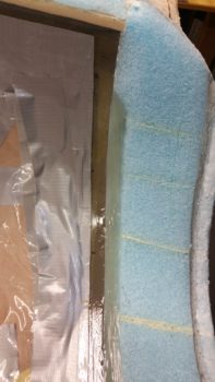
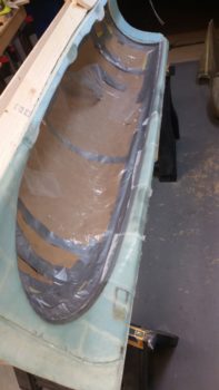
I’ve been pondering for a few weeks now just how exactly to deal with the inside aft bottom edge of the canopy.  The blue foam is wide enough back there but the canopy comes down so low that there’s only about a half inch of foam underneath the canopy bottom edge.  I had thought about using pour foam, but I really just didn’t want to mess with building the dams for the walls and edges.

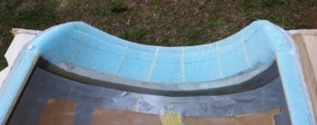
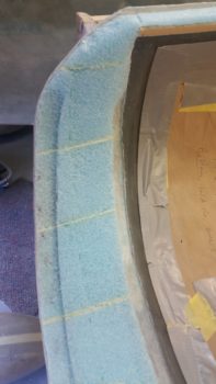
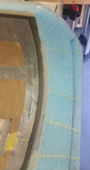
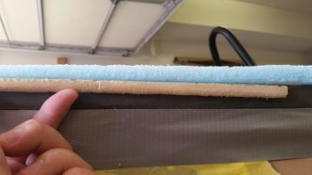
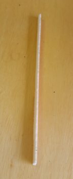
So I started off today by making up some PVC foam “quarter round” insert “molding” to increase the interior foam edge of the canopy and still have plenty of room for the canopy frame rail glass to grab ahold of the lower canopy edge.  Here you can see my testing out the fit of the PVC foam molding, which measure 0.2″ thick x 0.45″ high and is radiused significantly at the top to allow for a better glass transition from foam rail to canopy edge.

Here’s some shots of the first PVC foam aft canopy rail “quarter round” addition that I made up.

I then micro’d the new PVC foam “quarter round” additions to the aft left canopy frame in 3 spots.

Here’s a closer up view of the very aft foam “quarter round” addition on the left side aft canopy.

A little while later I did the right side aft foam “quarter round” additions in 2 spots.

Again, below is a close up of the very aft foam “quarter round” addition on the right side.

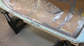
In addition, I also took a little bit to finish taping up the interior canopy so that only the edge to be glassed was exposed.  Then I finally finished sanding the interior canopy edge to allow for a good bond to the glass that will secure it in place.

With the leftover micro from adding the foam “quarter round” to the aft right side canopy, I threw in some flox and applied it to the aft end of the 1/8″ thick Balsa wood strips to reinforce the aft nose cover lip that interfaces with the very front edge of the canopy’s front skirt.

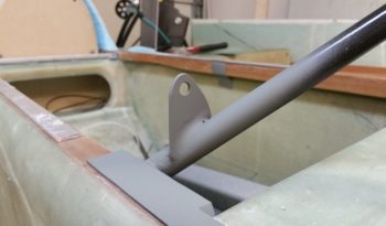
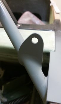
I spent a good 45 minutes doing another round of sanding on the Metal Glaze that I had applied to the canopy strut mounting tab on the roll bar.  After I got it shaped down very close to what I wanted I took it outside and hit it with a couple coats of primer.  Clearly there’s still some areas that need working, but with the primer applied they become much more apparent and easier to see.

After cutting the perimeter edge of the foam out and Dremeling the inside of the glass edge to clean it up for a nice flox corner for the entire remaining canopy side rails, I then got to work on the canopy’s front hinge mount.  Since the closed canopy hinge measures 0.270″ at the midpoint, I then set the depth of the hinge notch at 0.140″ vs the plans called out 0.150″.  I then spent another 45 minutes Dremeling and sanding the front hinge hard points to create the 0.14″ deep notch for the hinge half.  Now, this is just the initial round of cutting, sanding and shaping… tomorrow I’ll dial it it so that the hinge sits in the notched canopy rail nice and clean.

Since it was late and I had made quite enough late-night noise, I simply measured and marked the canopy’s aft hinge 0.14″ deep notch.

In addition to all the above, I spent a good bit of time drilling, chiseling, etc. to remove the cured micro that had oozed out onto the firewall when the turtleback foam pieces were glued into place . . . should have used thicker micro!

Tomorrow I plan on getting a good deal of glassing done.  At a minimum I plan to get the interior turtleback foam glassed and the aft end of the canopy frame.


Chapter 18/22 – Canopy skirt layup

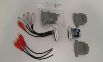
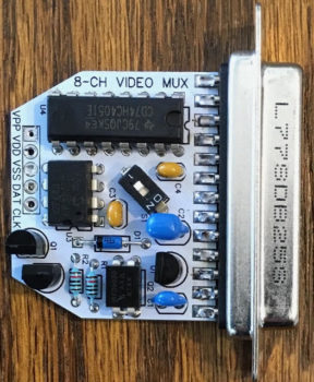
I started off today by checking the mail to find that I had received the 8-Channel video signal multiplexer (signal combiner/sequencer, AKA “Mux”) that Eric Page constructed and Alec Myers coded…. in collaboration with Bob Nuckolls.

As per usual Eric did a phenomenal job in constructing this Video Mux.  You may have noted above that there are 4 white RCA jack pigtails hanging off the interfacing D-Sub connector.  These were connected by Eric since my original & current requirement was for only 4 video cameras (as a reminder, I have one camera each on the fuel site gages, one top side camera on the pilot headrest looking aft and one bottom CL fuselage camera just aft of the nose wheel well looking aft as well).

Here’s the module’s board that Eric constructed.

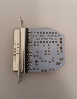
And the back side of the board.

I then got to work in the shop on finishing up the prep for glassing the canopy front underside with 3 plies of BID as per plans.  The first task was to finish taping up the canopy edge with first yellow paint tape, then duct tape over top of that.  After taping up the canopy edge to match the external canopy line, I then finished sanding the canopy edge to texture it to grip the BID plies.

I then spent about 20 minutes getting the 2 forward hard points sanded both level to each other and down to the foam canopy side rail elevation.  At first I used the Dremel tool to knock some surface glass off of the front hardpoint.  Then I switched to the “L” shaped Perma-A-Grit tool (still LOVE these Perm-A-Grit sanding tools… if you’re a builder and don’t have them, STOP what you’re doing and order them NOW!  Indispensable when building a foam/glass airplane!!!!)

After getting the front 2 hard points leveled and to the correct height, I then prepregged 2 plies of BID to combat every front line officer’s worst nightmare: “holes in the line!”  Yep, before I placed flox in the channel behind the aft wall of the canopy front skirt groove, I made 3 little mini wall inserts out of 2 ply glass and wedged them into place.

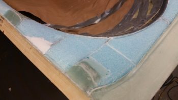
They may be a bit difficult to see, but here are the 2 ply BID mini wall layups placed inside the channel which is situated AFT of the canopy front skirt groove.  These mini walls will keep the flox inside the channel and from oozing out into the groove.

I then spent a good hour microing up the foam and creating flox edges along the canopy frame sides.

Since I had a fair bit of thick micro in a cup, instead of wasting it I then added a LOT of flox to it and created a thick flocro paste –heavier on the flox– to fill in the channel just aft of the canopy front skirt groove (where I placed the mini walls into above).

Here we have a couple shots of the floxed edges along each side of the canopy frame.

I then laid up 3 plies of BID using 6 separate pieces of BID.  The overlap for the first 2 pieces making up ply #1 is over towards the right side (left side in pic), whereas the overlap for the next 2 pieces making up ply #2 is on the opposite side.  The final 2 pieces that make up ply #3 I cut much larger so that the overlap actually created an entire new ply of BID . . . #4, which is situated in the middle 50% area of the layup where the front of the canopy frame is fairly narrow at the very forward tip of the canopy.

After the glass was laid up I then peel plied the layup.

Another shot of the glassed and peel plied canopy front underside skirt.

I then went to dinner with my buddy Rob and upon returning a few hours later I pulled the peel ply and very carefully razor trimmed around the inside edge of the glass that overlaps onto the canopy.

Inside shots of the razor trimmed glass on the interior canopy edge.

I also razor trimmed the glass overhanging the canopy front skirt groove aft wall.  This is of course the initial trimming and cleanup, with a more detailed cleanup coming tomorrow.

Here we have one final shot for the evening of the glassed canopy front underside skirt.  I really like the way the canopy frame transitions into the canopy here and think it will look really good once installed.

Tomorrow will again still be all about getting as much knocked out on this canopy as possible.


Chapter 18 – Front inside canopy

My friend and realtor Mindy came over this morning to discuss selling my house and also to see the progress on the Long-EZ build, which she had not seen yet in person. So before she got here I spent a good couple of hours today straightening up, which included a good 45-minute cleanup of the shop.

We then discussed the plane build for a good while as I showed her the fuselage and then the panel avionics and EFIS goodies.  After discussing house-selling stuff for a bit we went to lunch and BS’d even a bit more…. all this to say that my morning and afternoon was pretty much used up on Mindy’s visit, which was quite productive in itself.  BTW, during her visit I removed the canopy from the fuselage to enable her to look inside the fuselage.

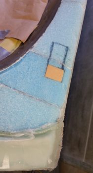
I got down to the shop a bit after 5pm and got to work making a PVC foam plug for a hardpoint that I’ll have in the front right corner of the canopy to mount what is essentially a hook to keep the canopy front lip from lifting up in the airstream.

The PVC foam plug is 0.8″ deep and comes to within a 1/4″ of the glassed outer surface of the canopy.

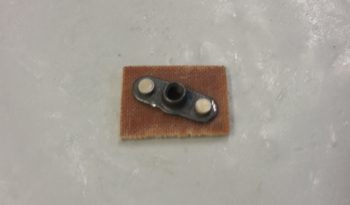
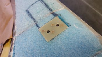
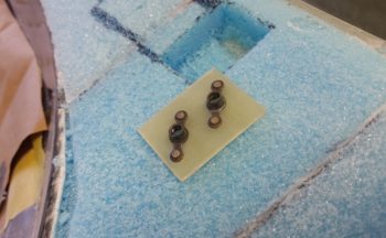
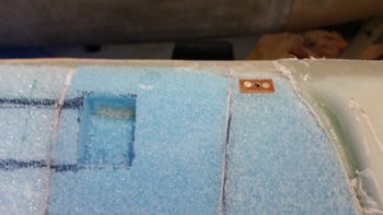
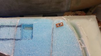
Using a piece of 1/16″ thick G10 Garolite I made a 2x K1000-3 nutplate for the front right corner canopy “hook.”

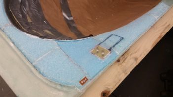
I also made a K1000-6 nutplate assembly for the right front canopy corner to allow mounting a small 1/16″ aluminum spacer plate on the canopy, whereas another 1/16″ spacer plate will be floxed to the top of the longeron.  Obviously added together they will make up a 1/8″ gap which is very close to optimal for compression of the canopy seal. [The left side has a hardpoint where I would mount the nutplate assembly, so I’m waiting until after the internal canopy frame is glassed to figure it out].

I glued the two pieces above in place using micro and flox and then left them alone to allow them to cure.

I then got busy on the mess that awaited me regarding the canopy front underside skirt layup.  I was correct in that the glass did in fact get folded up underneath itself and thus jammed multiple layers up into the groove and –worse yet– off the aft wall of the glare shield interfacing groove.

It took over 2-1/2 hours to get the front canopy skirt trimmed, cleaned up, and sanded with the extra glass down in the groove removed.

I then set the canopy back in place on top of the fuselage.  The elevation of the canopy vs the aft nose cover looked great…. in fact, at most in any dimension the mismatch is about 0.030″ or less… max.

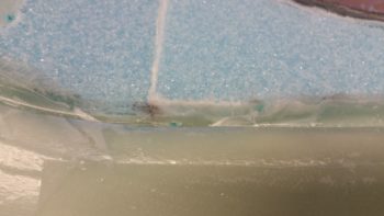
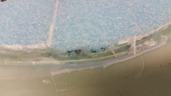
Here are a couple shots of the canopy skirt and aft nose cover interface . . . not bad!

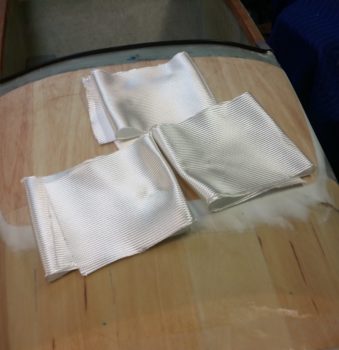
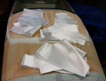
Since it was getting late, and knowing that it was too late to use the Dremel or Fein saw, I decided to get nearly everything prepped for the canopy forward interior 3-ply layup. Since the layup is “U” shaped, I decided to go with 2 pieces of BID per ply to conserve BID and simply overlap all of them…. below you can see the 6 pieces of BID that will make up 3 plies.

Here’s a wide angle shot of the prep to glass in the next forward plies of BID at the front canopy loop.

If you look closely you can see that I used a razor knife at all the edges that will enable a flox corner.  Since the flox is the only thing touching both inside and outside glass where it meets in the outboard corner, I wanted to make sure that the bond was robust so I’ll wait until tomorrow to Dremel the interior crud off of the inside glass (I can’t do it tonight because of HOA rules and just wanting to be nice to my neighbors!)

Tomorrow I’ll continue working on the canopy to try to get it well on its way before hauling it down to NC.