Chapter 24 – Airplane baker man!

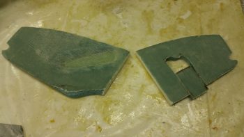
I started out today by pulling the peel ply and cleaning up the pilot thigh support ribs. I also cut out the glass from the mouse hole on the aft side of the right rib along with the overhanging glass from the layups.

I then trimmed the bottom of the right armrest to provide clearance and eliminate any rubbing on the fuel lines.

I also notched the bottom center of the left pilot armrest with a triangular opening to allow the armrest wall to fit over the pilot thigh support wedge duct when installed.  I also had to narrow the thickness of the wall on the outboard side of it that was adjacent to the air vent plenum duct in order for it to fit in its planned location.

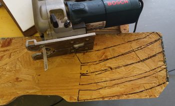
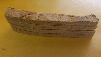
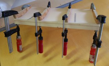
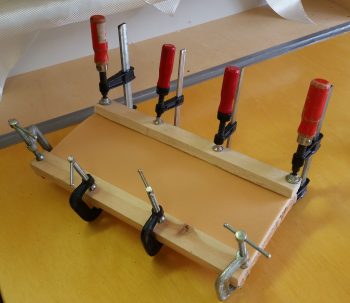
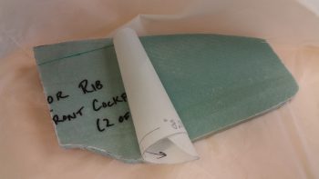
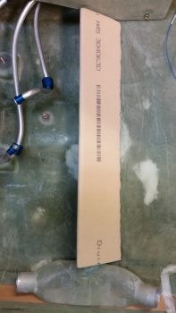
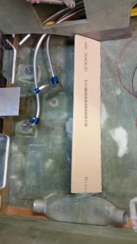
I then got to work on shaping the pilot thigh support seat floor.  First, I copied the thigh support rib profile onto a template.  Then I used the template to mark up a scrap piece of OSB chipboard to cut out 4 thigh support rib jigs.

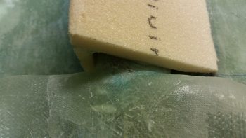
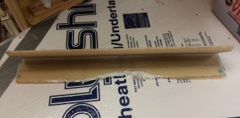
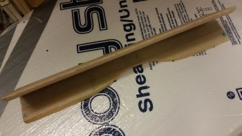
I then cut out the pilot seat thigh support floor piece from 3/8″ foam, and then clamped the 4 thigh support rib jigs to the bottom of the floor piece.

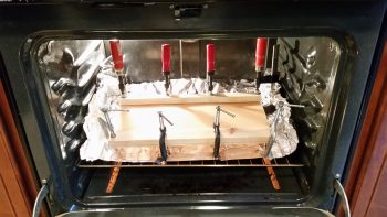
I then baked the jigged & clamped pilot seat thigh support floor piece in the oven for an hour at 280°.  In hindsight, it may have a been a bit too long to bake it, but in my defense there was no bake time listed in the plans!

I had to run out for a while after I turned the oven off and the floor piece started cooling down.

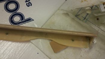
When I returned, I noted that there was a bit of waviness in the front & aft edges of the floor piece since the heating of the foam apparently produced some sagging in between the clamped rib jigs.  Moreover, these “scalloped” edges were significant enough that I thought about scrapping this floor piece and remaking another one.  But I don’t like wasting foam and to be honest, I kind of like the challenge of fixing a piece that’s less than perfect and make it work.

I pressed forward with the floor piece install and started working it until it proved to be unworkable, to see if it would . . . but it didn’t.

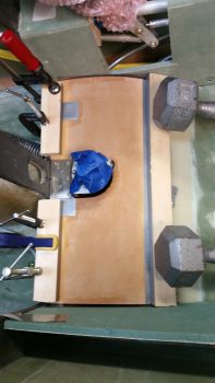
I wanted to lock in the CORRECT floor piece profile, so I decided to do a multi-part layup starting on the top of the floor piece surface (plans has you layup the bottom surface first). Since I needed to clamp both the front and aft edge to lock in the correct shape, I further decided to start with a large central ply of Kevlar –specifically to add puncture strength to a piece that gets stepped on every ingress & egress of the plane– and then add a strip of BID on both the front and aft edges after the center area floor piece profile was better locked into shape.  After these first pieces are laid up, I’ll of course lay up a ply of BID over the entire top surface of the floor piece.

As for the Kevlar layup, I started out by microing the surface of the floor piece top where the Kevlar ply will get laid up.

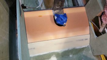
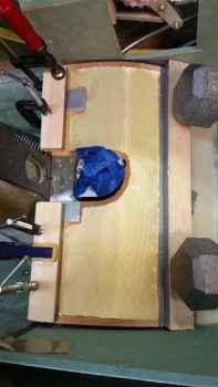
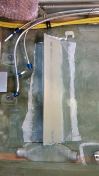
I then set the ply of Kevlar in place on the top of the pilot seat floor piece.

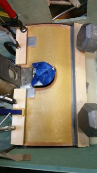
I then wet out the Kevlar.

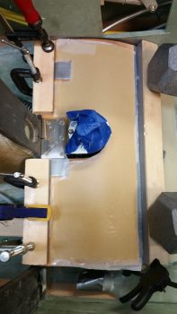
And then peel plied the Kevlar layup.

Tomorrow I’ll continue to glass the pilot seat seat floor piece in my attempt to both get it installed, but also to straighten out some of the front and aft edge waviness that was introduced during my heating of the floor piece foam plate.  Still, I think it should be fine.


Chapter 24 – Thigh support ribs installed

Today was a very busy day, primarily in a non-build way.  Still, first thing this morning I got up and pulled the peel ply, knife trimmed, sanded and cleaned up the 1-ply BID layup on each side of the 2 pilot seat thigh support ribs that previously was bare foam.

I then made a shallow channel in the foam on the front edge of each rib. I quickly whipped up some micro paste and filled these shallow foam channels. I then covered the micro on the front edge of the ribs with a piece of peel ply, respectively.

I then left for a good 6 hours to help some friends with some heavy lifting at their community yard sale.

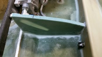
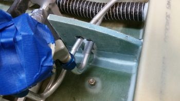
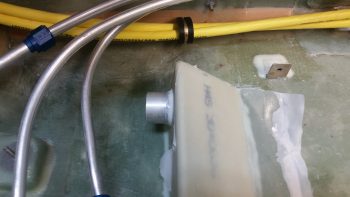
In the few-hour break between returning home from the yard sale and a planned outing for dinner and a movie with some friends, I quickly prepped, micro’d and then glassed the left side thigh support rib in place.  In a rare occurrence, since I was going to be late, I thought I’d get gritty and earthy and throw caution to the wind by NOT peel plying the left rib BID tapes.  (Note the Adel clamp mounted into the face of the pilot seat thigh support wedge duct)

A few hours later, I then prepped, micro’d in place and then glassed the right pilot thigh support rib.  Since I’ll eventual reinsert and glass the lower rib notch piece –and since time was not a factor– I decided to peel ply the right side rib install layup.

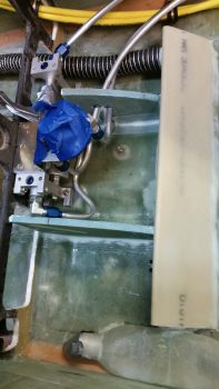
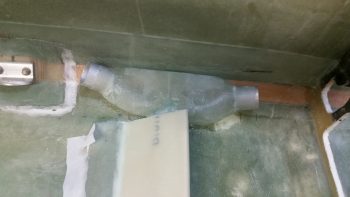
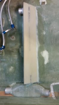
Here’s a wider view of the entire pilot seat thigh support rib affair.

Tomorrow will also be a bit lighter than usual on the build since I have to prep for going to Marco’s in order to help him as much as possible prep his plane for flying to RR.  I will say that my main goal for tomorrow is the thigh support cover plate that makes up a good portion of the bottom of the pilot’s seat.


Chapter 24 – Not much, thank you.

After doing some chores around the house, I had to run out rather unexpectedly mid-afternoon to help some friends that required some of my assistance.  I was out for about 6 hours and by the time I got home it was getting pretty late.

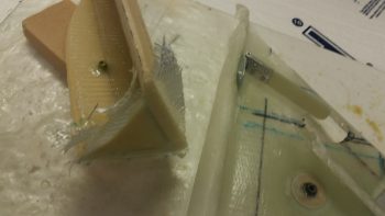
I wanted to get at least some glass “cookin’ in the oven” so I prepped & glassed the 2 pilot seat thigh support ribs on the one side of bare foam that each rib had.

Since I had cut out a small trough in the foam for the beginning of an elongated hole on the left rib, I had to decide whether to fill it back in or leave it.  I decided since I’ll be using wrenches during the installation and removal of the fuel selector valve to fuel pump main fuel feed line, I could use a bit of space between the rib and the line getting installed . . . so I left the trough.  I then angled the sides of the trough sloping inwards, and pressed on with glassing the ribs.

The glassing was uneventful with 1 ply of BID going onto the right rib, and 1 ply of BID on the left.  However, I did use an extra oval shaped ply of BID inside the trough and overlapping up over the edges.

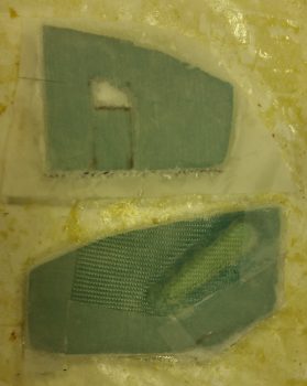
Also, I didn’t micro the insert piece –that I cut out of the right rib– into the rib since I merely wanted to get a ply of glass laid up on it.  The hole that you see above the insert piece is where the right and left fuel sump tank feed lines travers the rib to connect to the fuel selector valve.  Once all is set and I’ve locked in the the fuel system configuration, I’ll micro the fuel lines into the rib and glass the insert piece back into place (unless I choose to glass it in from the get go).

I then peel plied the entire right rib glassed face and the edges on the left rib.  After assessing the layups the right rib looked fine, but the left rib glass was having a bit of an issue staying attached inside the trough.  I have to say, this is when I miss having my vacuum pump set up for vacuum bagging because this is a perfect scenario for using it. Especially since after messing around with it for a bit, I realized it wasn’t going to play nice.

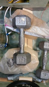
So I pulled out the big gun.  I covered the trough half of the layup with Saran (plastic cellophane) wrap and gently wiggled a small 4-pound sandbag into the trough, which of course overlapped onto the majority of the trough side of the rib.  Sometimes taking this type of action is tricky since there may be an unknown issue that can’t be seen, but I figured keeping all the glass compacted and in place nicely with minimal delams or air bubbles would be worth the minor risk of something going awry.

Tomorrow will also be a light build day, but I do intend to at least get these ribs glassed into the fuselage.


Chapter 21/24 – 3rd times a charm!

Yes, 3 attempts it took bending aluminum tubes to make the fuel selector valve to fuel pump crossover line!!! . . . more on that below.

Today I started out doing some research on how to revive some old Chartpak dry transfer lettering sheet that I have.  Apparently, over long periods of time they lose their transfer ability and they simply don’t work. Well, I tried a few of the home brew remedies of the Web and was able to get the letters off at least, but I just wasn’t overly happy with them.

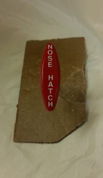
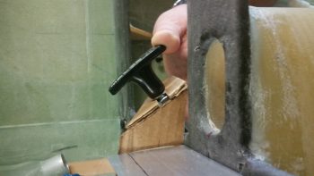
I wanted to use black characters on my red T-handle that I had designated as the Nose Hatch release handle, but it really didn’t look as good as I had envisioned.  So I punted and simply went with the fresh set of white dry transfer lettering that I have on hand.

As you can possibly imagine, it’s difficult enough to get these letters to line up on a flat smooth surface, and another thing entirely to do it on a curved contoured surface.  This is my excuse for the letter spacing not being perfect, but again –in my world– it’s darn close enough!

After getting the lettering transferred onto the red Nose Hatch handle, I took it down to the shop, taped it up and then shot it with about 6-7 coats total of matte clear.

In between the clear coats I started working on the fuel lines that connect to the Andair fuel selector valve.  Since I swapped out the valve fittings with the ones that I bought from Andair, which stick straight down vertically vs straight out horizontally, I hadn’t touched the fuel line connections since I was waiting until the fuel valve was mounted in it’s final position.

I was praying that I had enough length on each line to get to the fuel valve, since I had to lop off a decent amount of the curly-cue terminations of each fuel line in the craziness that I had undertaken to get them into the stock valve fittings while taking up as little space as possible.

In my new present tubing configuration I needed a decent amount of straight tubing just prior to the termination point to allow me to get the coupling sleeve on the line and still have room to flare it.  Yet just another reason I wanted to go with these new vertical fittings vs the curly-cue terminations… which made it really difficult to get a good flare with the coupling sleeve in place.

Well, apparently I had JUST enough tubing left to get to the new Andair fuel valve fittings. Still, it is all TIGHT and I will need to notch the lower right armrest a tad and contour the right underside edge of the thigh support top to allow for clearance with the right and left fuel feeds coming from the thigh support sump tanks to the Andair fuel selector valve.

I then cut and shaped the left thigh support rib to get it ready for glassing into place. Part of that prep involved pulling peel ply that I had applied when I laid up this piece back in mid-2012 … amazing!

Then, through the requisite trial and error fitting and sanding repeat cycle, I finalized the shape and got it into place.  My original location for this rib was very close to the stock location called for in the plans.

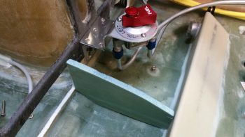
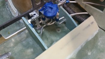
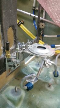
I then removed the fuel selector valve and its bracket to mount the fuel pump in place.  I then remounted the fuel selector valve and bracket.  I taped up the fuel selector valve because it’s a nice looking piece, and as I was mounting and removing it I noted that it was laying in a pile of tools, files, sanding blocks, etc. and for a minute thought that I had scratched it pretty good… I clearly needed to better protect the nice finish during the build process.

The fit of the left side of the fuel selector valve bracket and the inside of the left fuel pump frame is about as exact as could be.  Too close actually and I’ll need to trim the left side of the fuel valve bracket by at least 0.050″ to allow for clearance.  The clearance on both the instrument panel bulkhead attach bolts and the upper bracket attach screws is all good.

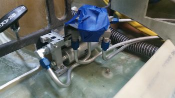
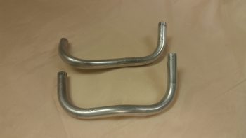
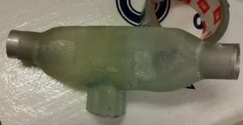
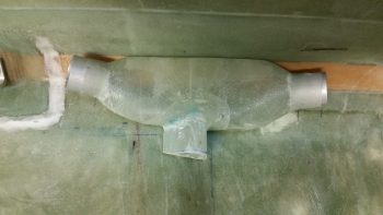
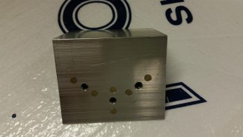
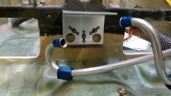
I then started the multi-hour process of shaping and terminating the 3/8″ aluminum tubing that makes up the fuel selector valve to fuel pump crossover line.  Amazing how many distinct requirements I had on such a short cross-connect tube.  First, I discovered I needed a distinct dogleg in the lower horizontal section of the tube to curve around the left tank feed line coming into the left side of the fuel valve.  Then there was the curve back, at about a 45° angle, to intersect the fuel pump fitting, which is a distinct angle change in comparison to the other side attached to the fuel selector valve.

Piece of cake, right?!  Yeah, after a couple of hours and definitely getting my tube cutting, bending and flaring practice in for the year!  Obviously I finally got it, and it’s the last bit of fuel line tubing bending I have to do on this plane! (I still have the brake cross-connect lines to do…)

Here are the previous 2 failed attempts  . . .

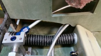
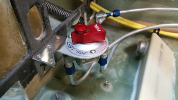
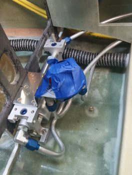
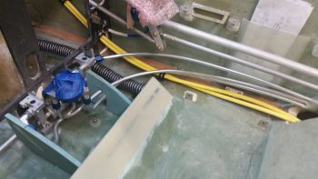
Another shot of the fuel selector valve to fuel pump crossover line, along with the other fuel valve connections.  Note the heater air SCAT tubing I set in place on the pilot thigh support wedge duct outlet.

I then spent a good hour getting the thigh support ribs configured and set in place.  As I stated previously, I had originally planned on having the left thigh support rib set in place at the plans location.  I even started notching the foam out to allow for the fuel pump’s left side fitting and the cross-connect fuel line to the fuel valve.  After pondering it for a bit I realized that it would just take too much work both in configuring, constructing and glassing the left rib simply to keep it in place at the plan’s location.  By kicking it outboard an inch to the left I eliminated all these issues & headaches…. so, that’s the spot!

On the right side there is simply no way that the rib can connect all the way from the aft side thigh support wedge duct to the bottom of the instrument panel bulkhead.  Not unless I never planned on removing the fuel pump.

Now, obviously hind sight is 20/20, but had I NOT used Clickbonds on the lower fuel pump mounting tabs and instead used embedded nutplates, I could have eliminated a LOT of my fuel pump mounting issues.  First, I could take the right side rib all the way to the bottom of the instrument panel bulkhead since I would have been able to slide the fuel pump in vs drop it in straight down. Even more helpful would be the fact that I wouldn’t have to remove the fuel valve bracket to get the fuel pump in or out…. the saving grace being that I don’t foresee having to be installing and/or removing the fuel pump a lot once the airplane is flying.

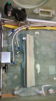
Here’s a wider angle shot showing all the fuel line runs in the pilot seat area, pretty much close to the original style as per plans, with some obvious distinct configuration tweaks I made on the fuel pump and fuel valve mounting locations.

I should note that the lonely Clickbond on the fuselage floor just aft of the fuel pump was originally for the 90 micron fuel filter supplied (and required) with the EFII fuel boost pump. I mounted this filter, and thus the Clickbond, prior to making my decision to go with the Holley Hydramat fuel pickups in the thigh support sump tanks.  Since the Hydramats filter to 15 microns, and I have one final 32 micron filter [as required by the Silver Hawk fuel injection system] at the firewall, there is simply no need for this 90 micron filter.  So…. out it went!

Between now and next week I do plan on continuing to knock out these build tasks, but admittedly it will start to slow the closer I get in heading down to Marco’s for our flying out to Rough River.  Hopefully I’ll see a bunch of you there!


Chapter 21/22 – Fuel Valve Installed

I started out today having a discussion with Mike from ElectroAir.  I had a few questions on the installation of the ElectroAir electronic ignition system, most being just crosschecks on what I was planning on doing and that I wasn’t going to screw anything up doing it!

There are a couple of connectors on their EIS (not GRT) Controller harness that I inquired about: the first connector –that I want gone– are on the wires running to the coils, and the second just a connector inexplicably (to me) placed on the controller’s ground wire.  The first will get replaced after I run the wires through the firewall to the coil, the latter connector will get removed altogether.  Both with the blessing of ElectroAir.

All this really relates to wire runs both in the hellhole and through the firewall.  That, in turn, relates to space required for wiring transiting holes through the firewall in the D-Deck / Turtle Deck / GIB headrest.

I then had a quick chat with B&C about the mounting requirements for the SD-8 Backup Alternator’s voltage regulator. The new electrical system requirement I picked up from them is that it’s highly recommended that I have a cooling fan for the SD-8 voltage regulator since apparently it runs a little on the warm side.

So, fan on the list to integrate into the GIB headrest.

I then integrated this new fan requirement into the electrical system, as well as moved the ElectroAir MAP sensor from the engine compartment into the Hell Hole, by reworking a number of my electrical diagrams.

Since I was on the computer upstairs updating my electrical diagrams, I took a good half hour to familiarize myself with Mike Beasley’s engine baffle templates.  I cut a few of the template pages into pieces so I could better get them organized, and after I had a decent understanding of what was going on I left them alone & headed down to the shop.

In the shop, I started off by determining the angle for the riser mount I’ll build to house the parking brake T-handle on the left side of the nose gear viewing window, and then a mirror one on the right for the nose hatch release T-handle.

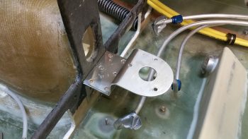
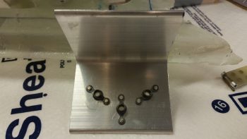
After spending a good hour determining dimensions & drafting up some ideas on mounting these T-handles, I then got to work on cutting, forming, constructing, and mounting the top fuel selector valve bracket to the lower fuel valve bracket.

Although I plan on having some sort of support brace to assist in securing the fuel selector valve, I also had planned on the valve being mounted a little aft and a bit higher than the plans valve.  Thus, the mounting of my fuel valve would incorporate a significant stepped cantilever design for the upper valve bracket.

Allowing for this stepped cantilever design, I chose a 0.090″ thick piece of scrap 6061 for my stepped upper bracket. I don’t have a bending brake, so I resorted to clamps (one of which I broke!), 2x4s, and a couple of different hammers to bend this piece of metal to my will . . .  ha!  Moreover, (specifically for Marco) I started off by cutting the scrap 6061plate to its 3″ width using my Skil saw that was conveniently available.  For the curved aft end of the bracket I used my jig saw with a metal blade installed.

I then clamped & pounded, clamped & pounded <insert choice curse words here!>, replaced a broken clamp, and then clamped & pound some more.  I had my phone charging so I didn’t get any pics of this sequence, but suffice it to say it worked out well enough.  Again, it won’t win any beauty contests, but it’s strong as can be and it’s pretty darn straight to boot!

I then used my new Cleco clamp to help hold the bracket in place (in hindsight I won’t use a Cleco clamp on something with a nice finish –which ironically is why I chose this clamp– since it marred the finish. Since this plate will get covered or painted anyway, it’s a good lesson learned) and drilled pilot holes in the aft row of screw mounting holes, placing a Cleco in each hole as I drilled them.

Due to the width of the drill, I couldn’t drill the forward screw mounting holes without imparting an angle on each of the holes.

So I removed the Clecoed-together upper and lower bracket assembly and widened the screw mounting holes to 1/8″, with the subsequent Clecos getting mounted into each hole as it was drilled.

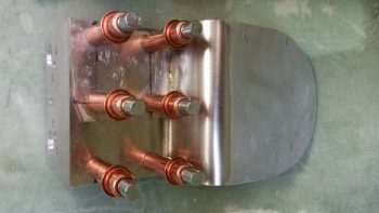
Due to my haste I also failed to get a shot of the 6 x K1000-8 nutplate assemblies that I drilled and riveted into place.  I had considered simply using 4 x #10 screws to secure the upper & lower plates together, but then after some thought I went with 6 smaller #8 screws.  Again, in hindsight I could have gone either way and now think the 6 screws may be a slight overkill, but it’s definitely secure!  Clearly, I needed 2 standard and 4 corner nutplates for this job.

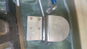
Once the nutplates were installed, I then mounted the top fuel valve bracket to the lower. I’ll also state that the alignment deamons reared their ugly head here –despite my intense efforts otherwise– and somehow my bracket alignment got off kilter about 0.030-0.040″. To be certain, the left & right edges weren’t perfectly aligned when I started, but the front edge was.  So I ended up filing the front edge to make the edge straight and allow for it to fit flush against the lower instrument panel.

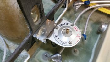
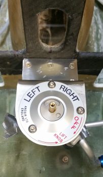
I then rounded up my installation instructions for the Andair fuel selector valve. Now, the Andair install directions would have you install the valve with the Left tank straight 90° left, the Right tank straight up, and the OFF position 90° to the right, like this: (L-9 O’clock, R-12 O’clock, OFF-3 O’clock). . . I changed that by rotating the valve a bit clockwise so the my Left & Right tank valve handle positions would be symmetrical, with my Left tank at the 10 O’clock position (45° left), my Right tank at the 2 O’clock position (45° right) in a  fashion, and my OFF at the 5 O’clock position (45° low right).

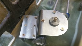
I then drilled the 1″ round center Andair fuel valve mounting hole, drilled the 3 each #10 screw mounting holes, and mounted the fuel selector valve.

I then removed the valve, countersunk the 6 x #8 bracket screws, and remounted the fuel valve bracket assembly onto the lower instrument panel bulkhead.

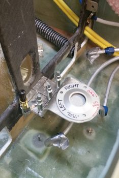
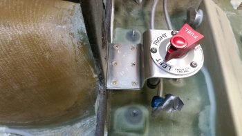
I then remounted the Andair fuel selector valve with its cover plate.

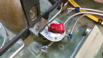
I then mounted the fuel valve handle.

And the parting shot of the evening: the fuel selector valve officially installed!

Tomorrow I’ll continue my pilot’s seat area build tasks.  To be clear, I can’t do the final install on the GIB area air & heat ducts until I figure out the cable runs and lengths to the 3 valves installed in the ducts.  To do this, I need to know the mounting configuration of the valve handles in the left pilot armrest.  Thus, in order to get the left armrest installed, I need to get the pilot seat thigh support ribs and cover in place.  So in an odd twist, the fuel valve I finished installing tonight has a direct bearing on me getting the GIB ducts installed!


Chapter 23 – Rabbit holes

Today I had a myriad of personal things to take care of early on.  When I got back to the build I really wanted to figure out some issues that I had run across when loading up the GIB headrest with components.

I had some questions for ElectroAir on their Electronic Ignition, and when I tried to call they were already closed.  When I checked out their site’s FAQ section, I noted their new requirement for mounting the MAP sensor: they now want it mounted on the cold side of the firewall, where before they stated to mount it on the hot side.  This new placement is in line with how GRT states their MAP sensor should be mounted, but throws a wrench in the works as far as how I have my MAP system configured…. so back to the drawing board.  Literally.

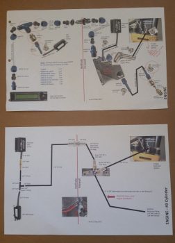
I didn’t want to just write a note and deal with this later, since the information I was collecting was all right in front of me.  I spent a few hours researching configuration options, figuring out fittings, and the physical install on each side of the firewall.  The end result was a couple of respective orders for very specific fittings (restrictor & barb), and an entirely new look of my MAP system by the time I was done.  In fact, below is a shot showing my MAP system about a year ago (top) and what it looks like now (bottom diagram).

In addition, although I don’t have a pic for this, I also spent a good hour updating my firewall components and pass-thru diagram, which has changed significantly from a year ago as well.

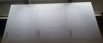
In prep for Rough River this year, I sent a note to Mike Beasley, Long-EZ builder extraordinaire, asking if he could bring his O-320 engine baffle templates he created a few years ago.  He had said I could get a copy, so I figured now was a good time.  Mike actually had soft copies of his templates, sent me those and I immediately went down to Staples and had them printed off.

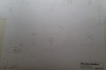
Here’s a closer shot of Mike’s engine baffle templates.

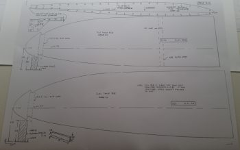
While I was at it, I loaded up pg A14 of the plans on my thumb drive to have it printed as well.  I need to dial in and refine the shape of the rather rough-cut ribs that I have in my Strake Leading Edge kit from Feather Light.

I have to say all the copies came out about as perfect as could be from what I can tell (there are tick marks on pg. A14 and it did print out spot on).  With my manifold pressure system issues put to bed, I can now move on with the build and get back to my internal cockpit configuration tasks.


Chapter 22 – No turning back… now!

Haha!

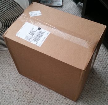
I didn’t get ANY actual building done on the plane today!  Why?  Well today I got a nice delivery from the UPS bubbas . . . you gotta love people who bring you airplane parts!

Hmmm? . . . a big box from GRT Avionics.  This can’t be anything but good!

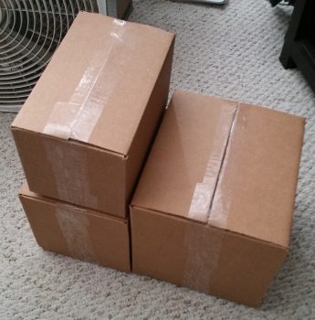
And what do we have here, 3 smaller boxes inside the big box.

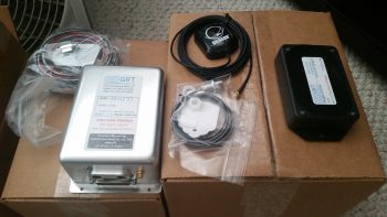
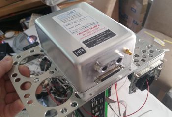
Small box #1 revealed HXr EFIS accessories: GADAHRS, magnetometer, GPS antenna puck, OAT probe, and wiring harnesses.

I had already located my preprinted label stash and as each item came out of the box it got labeled with it’s 2-digit component ID.  I also wanted to check the fit of the GADAHRS on the top cross mounting shelf of the Triparagon: perfect fit!

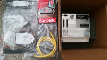
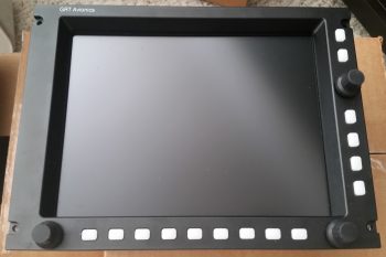
The bigger of the 3 boxes was the GRT HXr EFIS itself. I bought the smallest HXr EFIS GRT sells –the 8.4″ model– since I wanted to conserve as much panel space as I could.  I figured it would fit well and still have exactly the same features as the large 10.4″ and 12.1″ models . . . actually more, since those models don’t have the optional touchscreen feature that I ordered on this unit!

You can see the top layer of the box contained more wiring harnesses, a thumb drive, and a display unit cross connect ethernet cable (that I won’t use since the Mini-X does not have an ethernet port… the displays will talk to each other via an RS232 serial pair).

And then I pulled out the centerpiece of my instrument panel: the GRT Avionics 8.4″ Touchscreen EFIS.  When I started this EFIS journey years ago, I’d never imagine that the unit I’d get was even more capable than what I was asking for.  I have to say that I’m extremely happy with the configuration, outlay and capability of my panel and avionics!

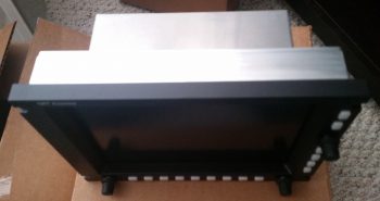
Here’s a shot showing the depth of the HXr EFIS.

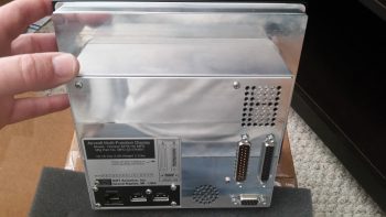
And the back panel.

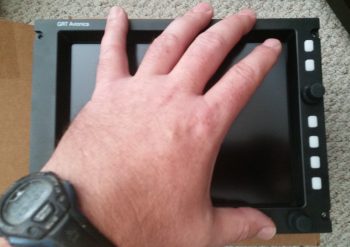
This shot gives you an idea of the actual size of the unit.  It’s not like I have gorilla paws, so this EFIS is a perfect size for a Long-EZ panel (in my opinion).

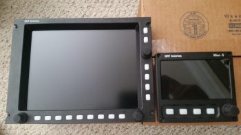
I’ll reflect back on how it is to plan something for literally years and then finally have it come to fruition.  This is my personal money shot right here.  Finally… my HXr PFD & the Mini-X MFD, together . . . where they belong!

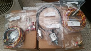
I then opened up box #3, which contained all the wiring harnesses and engine sensors for the GRT EIS4000 Engine Information (management) System.  Since I needed a different MAP sensor that doesn’t come in any of the EIS4000 packages, I ended up getting the basic package and then just adding a couple higher quality sensors to the lineup.

And here’s the very capable EIS4000 control unit.  A lot of builders simply place this in their panel and call it a day, and it will work well that way.  But to spice things up a bit all you need is one little 22 AWG wire to port all that info via serial data into the HXr & Mini-X and you can see all the engine data in beautiful, colorful graphical representation.

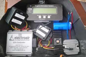
I can’t even begin to relay how many phone calls that I fielded today.  So besides inventorying the new orders and crosschecking interfaces with components I already have on hand, I finished out the evening by “simply” figuring out the configuration of my GIB headrest (aka “component storage facility”) which will house the following (top down, CW):

  • Hobbs Meter
  • EIS4000 Control Unit
  • B&C SD-8 Backup Alternator Capacitor
  • B&C SD-8 Backup Alternator Voltage Regulator
  • B&C SD-8 Backup Alternator Self-Excitation Bridge Rectifier
  • Princeton fuel level control unit – Left Tank
  • ElectroAir EIS (Electronic Ignition System) Controller
  • Princeton fuel level control unit – Right Tank

(That’s all . . . at least for NOW!)

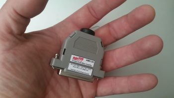
Oh, and let’s not forget the other item I also received in the mail today: my diminutive (cool in itself) MakerPlane AMX-2A Audio Mixer that allows me to take all my GNS480 system and NAV reporting messages, combine those with Trio AP audio reporting and CO sensor audio alarm, etc. and run it all seamlessly into my Dynon Intercom.  It has 10 channels so it can handle more than enough devices that I think I’ll ever throw at it.  And, as you can see, it’s literally the size of a 25-pin D-Sub connector backshell  [because it is one!].

Tomorrow I plan on getting back onto the build.  I’ll be honest though, as I start prepping for RR, and my 2 weeks of visiting friends in NC and VA, time will be in short supply.


Chapter 21/22 – Behold the wedge…er, duct!

It’s both… it’s the marvel of modern technology!

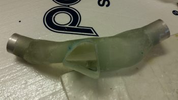
Today I started out by removing the air duct plenum from the fuselage where it’s new side appendage had been shaped by the thigh support wedge duct.  I pulled the peel ply, trimmed the triangle duct and cleaned up the plenum.

I had to trim down some glass edges inside the triangular duct, but after 15 min worth of work it was looking good.

I then set it back in its place inside the fuselage.   For reference the left sidewall is at the top of the pic.

I then mocked up the thigh support wedge duct over top of the duct plenum to see how it fit.

As you can see, the new air feed into the thigh support wedge duct fits nicely.  My next task was to install these 2 components into the cockpit permanently, but first . . .

I wanted to finish riveting the K1000-3 nutplates to the fuel selector valve bracket. Below is technically the aft side of the bracket.

While this is the front side.

I drilled the first 2 of a number of lightening holes on the fuel selector valve bracket, and then mounted it in place just to check that all is good.  And it is so far!

Here are the 3 fuel selector valve bracket bolts from the inside of the nose wheel well.

With the fuel selector valve bracket mounting bolts all taken care of, it was time to permanently mount the thigh support wedge duct and the duct plenum into the cockpit.

I whipped up some micro using fast hardener as usual, then micro’d/flocro’d these two pieces in place.

This pic may simply look like it did before, but this time they’re permanently mounted.

I then took about 20 minutes to sand the aft edge of the thigh support wedge duct to fair in into the existing seat pan.  Once I finished sanding and vacuumed up all the mess, I glassed the thigh support wedge duct in place with 2 plies of BID, overlapping onto the cockpit floor both front & back.  I then peel plied the layup.

A couple hours later I razor trimmed the layup and snapped this shot of the duct plenum, mounted in place permanently.

I then cut the glass out of the 1-1/4″ diameter hole for the aluminum duct vent tube, which will be used to connect SCAT tubing to the thigh support wedge duct.  I then pulled the front peel ply strip and the peel ply immediately around the duct vent tube hole.  I then micro’d the 1-1/4″ OD aluminum duct vent tube into place.

I then removed the peel ply from the rest of the pilot seat thigh support wedge duct.  The pics below are simply a wider angle and closer up view of it.

Again, tomorrow I will continue to press forward with internal cockpit stuff for at least another few days until l get the GIB & PIC area heating & air ducts in place.  In addition, by next weekend I plan on having the pilot seat area thigh support, fuel valve structure and left arm rest installed (including throttle quadrant).  Then I can sit in the airplane and finally determine exactly where my nose components need to be located.  Finally, I’ll continue to work GIB area component installs as well prior to the strakes being installed.


Chapter 21/22 – Valve #3 complete!

I started out today doing some electrical system housekeeping.  I keep a listing of all my electrical system components and their 2-digit identifier code used in my wiring label scheme.  Well, over the past 9 months I’ve had some major changes to some of the electrical subsystems and while I’ve kept up with the actual wiring design, the code tracking has room for improvement.

I updated my database and printed off a bunch of 2-digit ID labels and tracked down the stuff that needed labeling.  I’ve also rewickered a lot of lighting circuits and some switches, so I updated those and my switch tracking diagram as well.

I then got on to the task at hand, finalizing the components for the PIC/GIB air distribution valve, fondly known as Valve #3. Since its construction involved mechanically putting it together, with no epoxy or stuff requiring drying times, I kicked the actual construction of it down the road until I got a gap, while stuff was curing, to do it (see end of post).
I then got into stuff that needed time to cure.  As I was drifting off to sleep last night I was thinking about the wiring traversing under the pilot seat thigh support and decided to mount a couple of the smallest RivNuts I have on hand into the face of the pilot seat thigh support wedge for Adel clamp hard points.  Much, much easier to do them now than later on.  And these things weigh like a microgram, so any added weight would be the scant few grams of flox to hold them in place.

Along with the 2 RivNuts, I figured out the required shape of the right side end piece to cap the thigh support wedge and contain the flowing air, which, once reaching the end of the road inside the thigh support wedge duct, will make a hard left turn going forward again through SCAT tubing until reaching the glass vent assembly for my right foot.

So I got to work and micro’d & glassed the small end cap foam piece in place with a ply of BID both inside and out.
Here you can see the pilot seat thigh support wedge right end cap piece glassed in place with 1 ply of BID.  You can also see the right floxed-in-place RivNut Adel clamp hardpoint and the floxed in place (only floxed at this point) Valve #3, which I drilled & riveted after I laid the wedge duct end cap piece.
Not too much longer after I finished messing about with installing valve #3 with flox into the ductwork, the wedge duct end cap piece layup was ready for razor trimming.
Here’s a shot of the thigh support wedge duct end cap piece on the inside.
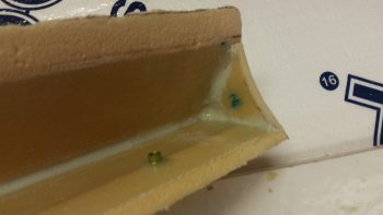
In my attempt to make things much easier in the build process I try to anticipate what next steps will have their difficulty amplified if not done sooner rather than later.  Again, I really strive to get the proper sequencing down to make the build flow much smoother.  Of course that’s the goal I aim at, but obviously don’t always hit my mark.  However, I think I did alright in determining that with the available room afforded to me once the thigh support wedge duct was floxed/micro’d in place, drilling the 1-1/4″ diameter hole for the SCAT tubing connector was going to be tough.

That being the case, I grabbed my trusty hole saw kit and drilled this baby out.
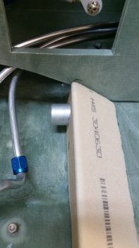
I want the connecting SCAT tubing to run as close to the fuselage floor as possible, so I angled the aluminum tubing piece downward a bit.  This required that I trim it down a bit on the inside of the wedge duct if I wanted to obtain the most optimized airflow as possible.
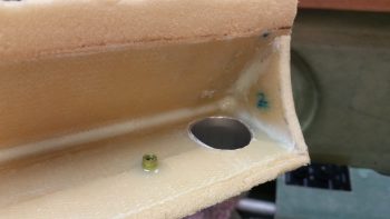
Here’s a shot from the front.  I threw the Adel clamp in there to show the spacing and that the wires being secured by the Adel clamp will simply travel right underneath the duct SCAT tubing connection.
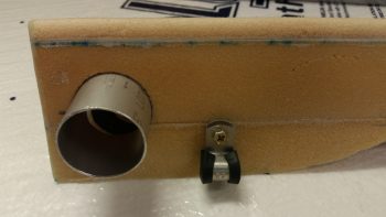
Before I mounted the pilot thigh support wedge duct I had to do 2 things:  First, I needed get air flowing out of the under-armrest duct “plenum” into the cockpit-crossing wedge duct.  I outlined the wedge duct’s right side end cap with tracing paper, cut it out and then transferred that to a piece of urethane foam block, and then cut out the duct shape.  This was just a hair more undersized than the inside of the wedge duct to allow for general fitting and glass thickness.
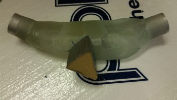
I then transferred the shape onto the intersecting side of the sidewall duct plenum and cut the same-shaped hole into the duct plenum.  I worked with the foam wedge & the hole cutout to the point where the foam wedge could be mounted –unmarred– into the duct plenum side hole.  I then duct taped the urethane triangular foam piece.

I then tested it out by temporarily mounting both the sidewall duct plenum and the thigh support wedge duct in place.  I then realized the aft side foam wedge fit fine in the wedge duct, but there was a considerably gap at the front. So I cut another piece of foam and taped it to the face of the existing protruding foam wedge form.  One slight mod later and I then taped up the foam form addition and was ready for glassing.
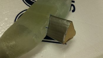
Here’s the foam form piece in place right before I glassed it with scrap BID pieces.  I made the triangular form a bit longer than it needs to be to allow for trimming.  This will allow it to traverse through the 3/8″ left armrest sidewall and still mate nicely into the left side wedge duct entrance.
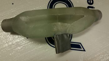
I whipped up some MGS285 epoxy with fast hardener (FYI, my 285 fast hardener doesn’t seem to cure quite as fast my 335 hardener… maybe a hardener age issue?) and glassed the new triangular “T” section of my sidewall duct plenum.
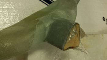
And peel plied the layup.
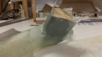
For better topic flow I’m showing the below pics now, although it came after I drilled the fuel valve bracket bolt holes.

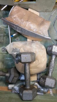
I took the “green” state cured layup assembly above and mounted it into the fuselage in the duct plenum’s final position, which in large measure was determined by the interface of the duct plenum’s triangular air duct feed into the thigh support wedge duct, which I then set in place over the glassed (and peel plied) triangular foam form.  After getting the final locations dialed in, I then weighed it all down in place to replicate the final installation positioning.

I had previously taped up both the fuselage floor and the inside of the thigh support wedge duct with duct tape so that no epoxied bits would attempt to stick permanently to anything.
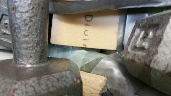
Here’s a closeup of the target intersection in my attempt to get the intersection as clean and leak free as possible, although the actual physical interface is more important at this point than possible leaks.
In reality, I let the layup above cure for a bit before doing the whole mock install thing while I drilled the fuel valve bracket bolt holes through both the fuel valve bracket and the Finnish Birch plywood hardpoint that I embedded into the base of the instrument panel –as per plans– back in 2011.  BTW, this was precursor #2 that needed to be completed before I mounted the thigh support wedge duct for good, since I wouldn’t have the right drilling angle, or space to do so, with the wedge duct mounted & in the way.

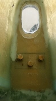
After a bit of wrangling and trying out some gymnastics moves… nearly standing on my head inside the cockpit… I was able to determine the location and spacing of the 3 AN3 bolt holes that I would drill through the fuel valve bracket into the instrument panel’s wood hardpoint.
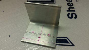
I drilled 3 small pilot holes into the fuel bracket as guides for the bigger holes.  I’m using 3 bolts vs the plan’s 2 bolts since the fuel selector valve will actually sit just aft and above this bracket.  Thus, technically this is the fuel selector valve bracket’s bracket.  Clearly, with the type of cantilever action going on here I need as much strength as I can get.
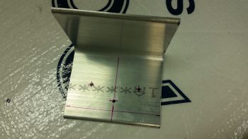
I then spent some time dialing in the exact fuel selector valve bracket location, then took the plunge.  Using my long drill bits I first started with a 1/8″ bit and drilled the holes.
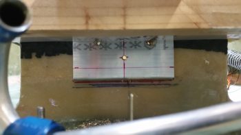
I then stepped up to a 10″ long x #10 drill bit and drilled the final bolt holes through both the bracket and the panel wood hardpoint, with the resulting mess shown below.
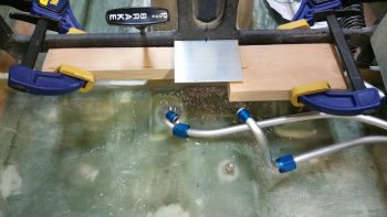
Here you can see both the 3 bolts installed and the aftermath of the drilling operation.
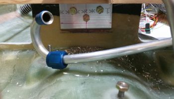
And just another shot of the temporarily installed AN3 bolts, with the area cleaned up.
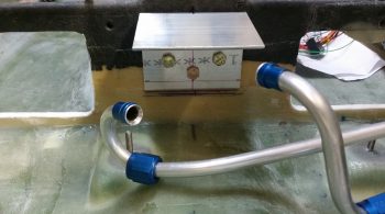
Finally, here’s a shot of the 3 fuel selector valve bracket’s AN3 bolts poking through into the nose wheel well.  The bolt on the left looks like it’s angled down a bit, but that’s just an optical illusion since it’s shorter than the other bolts.
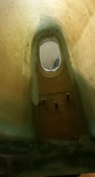
I then removed the 3 bolts and took a small bit of leftover epoxy I had on hand, mixed it with some alcohol, and treated these wood holes and most of the other ones I could find on the fuselage.  Treating the wood holes with alcohol-thinned epoxy allows the wood to absorb the epoxy and coats it so that any moisture is minimized and your bolts don’t rust inside the wood holes (this action kept me from finalizing the riveting of K1000-3 nutplates to the fuel valve bracket since one hole had been pushed slightly out of round by the wood piece I had clamped in place to secure the fuel valve bracket . . . since these holes were still wet).
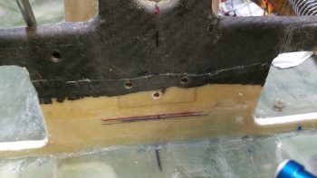
With my valve #3 having sat on the sidelines for quite a number of hours, allowing for the flox to cure, I then drilled 2 holes up through the duct reinforcement plate & extra plies of reinforcement glass, into the floxed valve attach plate.

As a point of note, valve #3’s position below would have ALL the air flowing forward to the pilot.
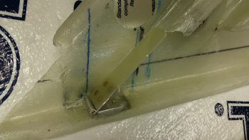
I then riveted –in not so pretty fashion– 2 round head rivets to secure valve #3 in place.

Again, below I placed valve #3 in the position showing its configuration with all the air flowing back to the GIB vents.
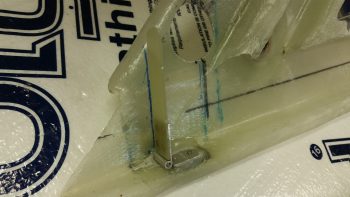
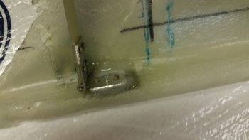
Here’s a closer shot of the rivets & flox securing valve #3, the PIC/GIB air distribution valve, in place.
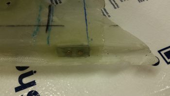
And a shot of the 2 rivets from the underside and external duct view.
Tomorrow I plan on pressing forward . . . so stay tuned folks!
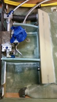


Chapter 22/24 – Your seat, please!
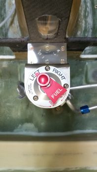
I got a lot of stuff done today although from only the two pics below you may not know it.

I started off doing a hard assessment on the airflow under the pilot seat thigh support wedge that also serves as a cross-fuselage air duct for providing heat up to my right foot. I calculated the airflow a number of different times and finally decided that the internal baffle the I was considering glassing in (essentially a false duct floor) was not needed so I pressed forward.

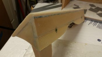
I micro’d the 1/4″ front wedge extension piece –or spacer– onto the bottom of the front 1/4″ vertical wedge wall.  I then glassed it in place with 1 ply of BID.

A number of hours later I razor trimmed the edges.

In addition to the above layup, I also did an extensive assessment on the components that will get installed into the left PIC armrest.  I played a bit of Tetris figuring out exactly how all the bits n pieces would fit.  Specifically, I took a hard look at the oil heat and seat warmer wiring and components’ space requirements.  This of course is all in prep so that in the next week or two I can start installing the left armrest console and internal components.

Lastly (again, no pics) I spent well over an hour designing and cutting the pieces for the PIC/GIB air distribution valve (valve #3).  I think tomorrow I should finally get valve #3 mounted into the ductwork so that I can install the GIB area air & heat ducts.