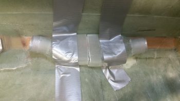
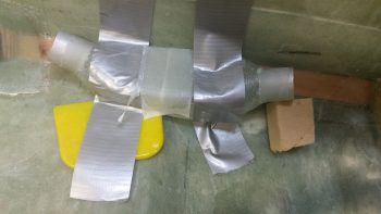
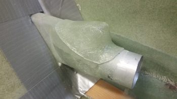
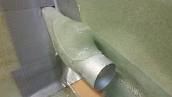
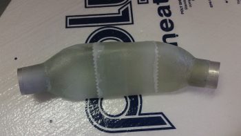
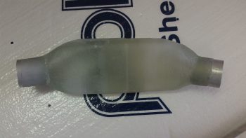
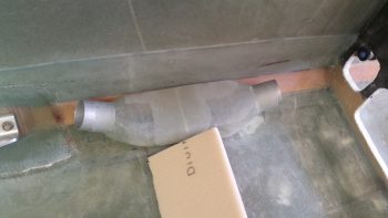
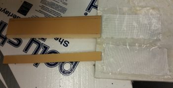
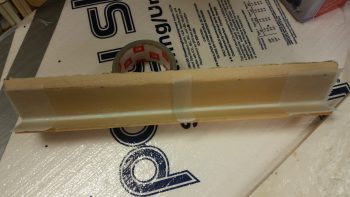
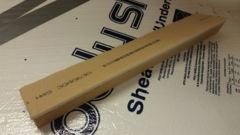
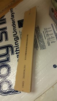
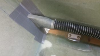
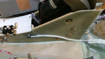
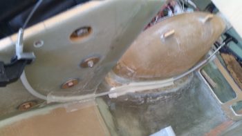
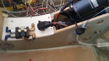
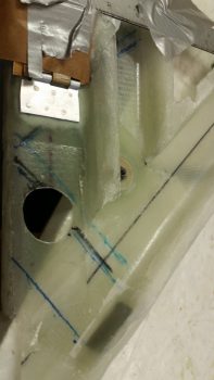
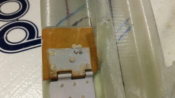
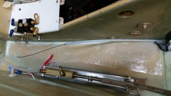
I started out today pulling off the peel ply from the aft side duct piece that will be joined to the forward side to make up the middle duct assembly, or “plenum,” in the pilot seat area. After removing the foam form and cleaning it up, I then taped the 2 midpoint duct pieces into place in the fuselage.
I then laid up 1 ply of BID over the exposed joint of the 2 halves. I then peel plied the layup.
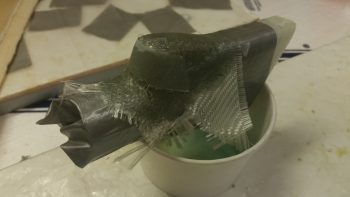
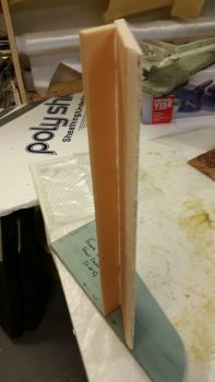
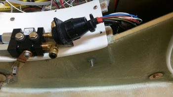
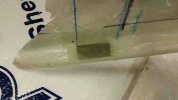
I made up a bit too much epoxy so when I finished the layup above I quickly shaped a piece of urethane foam and taped it up on the first duct piece coming forward from the pilot seat back. I then laid up 2 plies of “trash” BID over the taped foam “duct bump.” This raised protrusion will be the entry point for the #3 valve control cable, which will run through the duct and control the valve internally.
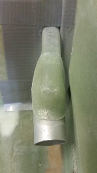
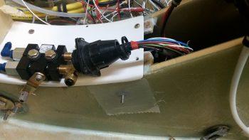
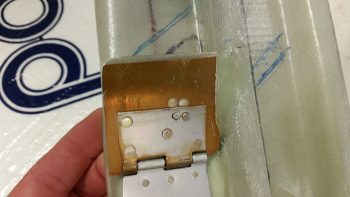
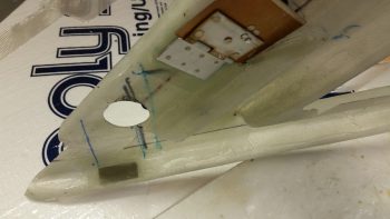
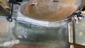
A couple of hours later I pulled the bump layup off the duct, removed the tape and pulled the foam form & tape out. I then trimmed the glass and set the control cable entry bump back onto the duct.
A head-on shot of the control cable entry bump set on the duct.
I then worked on the configuration of the pilot seat initial thigh support wedge that also serves as a cross-cabin air duct.
Since I needed to increase the top surface angle, with the front edge coming up, for a better intersect with the actual thigh support plate, I cut and shaped a 1/4″ thick foam bottom edge spacer. This took some trial and error to dial in due to the curves in the fuselage floor/seat pan. I also needed to finalize my glassing sequence and layup schedule, but it was getting late so I left it for later.
I did however layup the final BID tape joining the front & aft pieces of the PIC seat area duct “plenum” together. I then peel plied it.
A few hours later, I pulled the peel ply off the second and final ply of BID joining the front & aft pieces of the PIC seat area duct “plenum”.
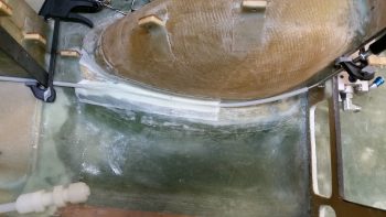
Of course then I had to mock it up to check it out. Fits like a glove and I think it will work out perfectly. I do have some more glassing to do on this component though since I need to make an exit duct on the inboard side that feeds air into the pilot seat thigh support initial wedge/duct.
Tomorrow I’ll continue to finalize this PIC area ductwork and initial thigh support structure, but I’d also like to finalize valve #3 on the GIB area air ductwork.
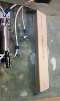
I tested out my cell phone camera and although the portrait/landscape indicator is not working, apparently the camera is still automatically orienting itself correctly. I took a short video to show the installed Matco parking brake valve lever cable push/pull actuation.
I then cut a piece of 3/8″ foam for the initial approximately 3″ that makes up the start of the wedge shape that is the pilot’s seat thigh support. Basically what I’m doing is make the aft few inches of the pilot’s seat thigh support a triangular built-in air duct. Obviously the aft side of the 2 interior thigh support ribs will now have their tapered aft ends cut “square” so they mate up with the wedge-shaped duct that I’m making below. This is all to get the warm air over through the duct system to my right foot. Gotta keep those tootsies warm people!
After I cut the top 3/8″ piece and shaped it, I then cut the front upright –or front wall- of this wedge-shaped duct. This smaller pieces is 1/4″ foam. Since I had a scrap piece of BID that would cover half of the internal side of this wedge duct assembly, I simply cut the other half off the roll and went with 2 pieces (1 ply) of BID. As per my norm, I prepregged the BID.
The entire width of the thigh support is 17″, the same as a stock plans-built Long-EZ. A long time ago, when I widened the fuselage 1.4″ at the pilot seat bulkhead, I was more concerned about space at the shoulders. Thus, instead of widening the thigh support (the aft seat pan is a bit wider since the bulkhead is wider) I focused on widening each armrest a bit more.
I then used fast hardener to mix up some micro to glue the 2 foam pieces together. (Unfortunately, this effort wasn’t simple and required a good hour of trial and error fitting & some resanding to get it all dialed in before joining the 2 pieces, thus the reason for the overhang of the top piece you can see in the pic below). I held the small piece in place with pins to immobilize it as the micro cured.
I spent a good hour prepping some other tasks while the micro cured, then while it was still tacky but structurally sound I laid up 1 ply of BID on the internal side of the wedge PIC thigh support duct. I then peel plied it at the BID ply overlap and each end.
A couple hours later, after the glass was cured, I knife trimmed the glass and cut off & sanded the front overhanging piece of foam.
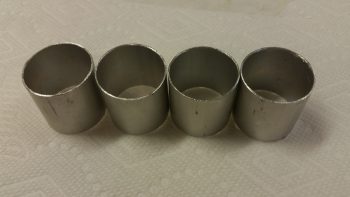
I then took my 1.25″ OD x 0.0.35″ walled 6061 aluminum tube outside and cut 4 each 1.25″ long pieces for subsequent use for connecting the 1.25″ ID SCAT tubing to the respective ducts that require it. I then spent a good 20 min cleaning up the edges on all these duct tube transition pieces.
As far as ducts in the duct network that “require” a SCAT tube interface, or cross connect, I determined that with the COMM & NAV COAX antenna cables being situated right behind the air duct as it initially enters into the PIC area through the lower left pilot seat, that I should make the transition over the left seatbelt mounting bracket SCAT tubing vs. glassing a hard, permanent duct.
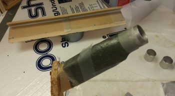
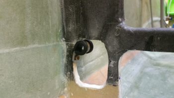
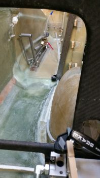
As you can see, when I finalized the shape of the duct coming out of the duct hole in the lower left pilot seat, I simply ran it out a few inches and capped it with one of the aluminum tube pieces I just cut.
The duct tape around the hole in the pic below was for making a flange on the duct that would allow me to later flox the duct piece in place. Instead, I won’t be using that tape and will simply attach the duct piece to the lower left pilot seat with small BID tapes.
I’ll also note that I had planned on not having any of this duct piece enter the seat back duct cutout, but I then decided to leave a good lip so that it would be much stronger, and so I wouldn’t have any duct alignment issues. Yes, it will cost me a very slight penalty in airflow, but since I’m reducing my tubing diameter anyway by utilizing the 1-1/4″ ID SCAT tubing, I think it will be matched fairly close regardless.
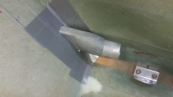
Here it is with the SCAT tubing slid in place. The area at the far right of the pic below is where this SCAT tubing piece will end and reattach –via an aluminum tube insert– back into the glass ductwork.
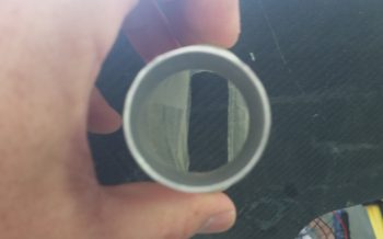
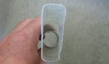
Here’s a couple shots showing the internal dimensions and airflow of the duct piece.
As I’ve already noted, I decided to make the duct transition over the left pilot seatbelt bracket SCAT tubing, primarily to ensure I can run my COAX antenna cables somewhat pain free, but I have a requirement to do something along that lines at the front part of the pilot seating area at the instrument panel as well.
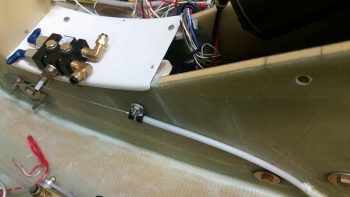
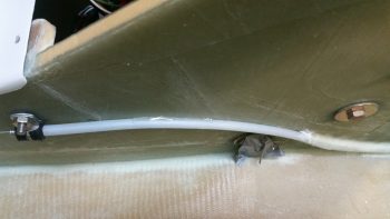
The hole in the lower left instrument panel is a rounded square hole that my throttle handle cable connector needs to fit through. And it can just barely fit if I remove the Adel clamp (IIRC!). What is certain is that the throttle handle cable connector will NOT fit through that hole (for mounting, servicing or upgrading) if there’s a permanently mounted glass air duct running through that hole. Yes, I could glass a unique removable duct to go through there, but running a length of SCAT tubing is just the easiest & fastest option. By using a length of SCAT tubing to transition the instrument panel, then I ensure that both throttle handle cable connector remains removable as does the SCAT tubing. Moreover, they’ll fit and play nicely together.
Taking into account all I stated above, then what I have in the lower middle area of my left armrest is a 2-headed snake, one at each end. I have an aluminum tube connector ⇒ glass duct ⇒ aluminum tube connector. Hmmm… if this is the setup then you may ask why not just run SCAT tube the entire length under the armrest from point A to point B? Well, because there’s a point C. In between these 2 aluminum tube pieces that connect to SCAT tubing, is the duct outlet that flows through the wedge-shaped duct at the front edge of the pilot thigh support. Again, this carries air over to the right foot vent.
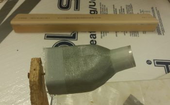
Since I want to minimize the footprint of the air ducting under the left armrest, I’m trying to follow the contour of the cockpit seat pan & floor as best possible. At the corner junction of the fuselage sidewall and floor (seat pan) the contour actually changes. To allow for this I made up a front duct foam form and a separate aft side duct foam form, each with an aluminum tube connector to cross connect to SCAT tubing. (These will be joined together into one duct after they are glassed separately and I pull the foam plugs).
Since the front side of this under-armrest sidewall glass duct “plenum” was the more complex of the 2 ends, I decided to knock it out first. As per usual, I made up the form with urethane foam and then covered it with duct tape. Normally these ducts are made by taping up the foam to the sidewall and using the sidewall as part of the form, with a resulting flange created on the duct used to mount the duct later on. However, since the space is tight with the left armrest upright sitting adjacent to this duct AND the requirement to glass all around the aluminum transition tube, I went ahead and glassed all sides of with it out of the fuselage. However, the bottom side is mainly open so that the existing fuselage corner will still act as the duct bottom wall.
Tomorrow I’ll continue to work more on the pilot seat area duct work. Since I have the initial pilot seat back duct piece completed, I can now better figure out some of the cable control routing to the 3 duct valves aft of the pilot seat.
I started out today adding a sub-page to Chapter 24 for the GIB kick plate when I realized that my page addition had inexplicably wiped out about 3/4 of my build log link menu that shows in the upper right hand corner of this site. I was able to recreate it after about 1.5 hours. I then got on with my original task to port over my build posts to the build log. That in itself took over 2 hours. Finally, I tweaked the Chapter 9 build page by parsing it out into different sub-pages to make it a lot more organized. Tack on an hour+ or two for that as well.
I then finally made it down into the shop to pull the peel ply off the Matco parking brake Adel clamp hardpoint Clickbond layup. I cleaned it up a bit and it all looked good.
I then mounted the Adel clamp to the Clickbond and also terminated the control wire into the brake valve lever arm nut. I worked the parking brake back & forth a bit (brake on & off) and the action was nice, solid and smooth. (I was going to take a quick video of it but my phone is stuck on portrait mode right now for some reason!).
With everything secure on the front end, I then positioned and 5-min glued the remaining forward parking brake control cable conduit. It may seem unnecessary at this point to secure the conduit, but I simply want to ensure that it never gets snagged, hung up on or in the way.
As the prior two secured cable conduit areas, I filled the voids around the cable conduit with micro and then glassed 1 ply of BID over it. I then peel plied the layup.
Besides the parking brake, tonight I worked extensively on the pilot seat base cross duct. There was a lot of interesting stuff to come out of the initial mockups of the pilot seat base cross duct, but I think the biggest impacting one is that I learned that I had to move the planned location of my ELT to ?!? I have some ideas, but I need to dial it in… soon.
I also assessed the duct situation and drew a bunch of hash marks all over the inside of the pilot seat area. I was planning on building the PIC/GIB distro valve (valve #3) for the heating duct, but it got too late and I couldn’t cut the material due to the noise it would make.
However, tomorrow is another day! Since I’m more than caught up on my website tasks, I seriously do intend to get my hands really dirty on this build tomorrow.
Today, before I headed off to my neighbor’s Labor Day cookout, I 5-min glued the next forward section –about 5 inches– of the Matco parking brake valve control cable conduit to the bottom corner edge and side of the left NG30 plate.
I made up some micro and applied it around the Nylaflow cable conduit, and then laid up a prepregged 1.5″ x 4.5″ ply of BID over the top of that segment of Nylafow cable conduit. As with the previous layup, I peel plied both the top and bottom edges of the layup (sorry for the slightly blurry pic…)
Here’s a shot showing the proximity of the conduit layup that I just did to the Matco parking brake valve. Also note that the position of the cable conduit that I just attached to the NG30 plate is the first half of what will essentially be an “S” curve in the conduit.
About 10 hours later, after the cookout, I got back in the shop to remove the peel ply off the layup, and clean it up a bit. I then confirmed where the parking brake control cable (the actual cable, not the cable conduit) Adel clamp location was required. I then attached a Clickbond hard point for the Adel clamp with 5-min glue, by using the whole assembly mocked up on the cable (not shown).
I then added a scant bit of flox around the edges of the Clickbond for transition, and then laid up 2 plies of BID over the Clickbond. I then peel plied the layup.
I needed to get the Adel clamp mounting Clickbond mounted and glassed since the next attaching of the cable conduit will overlap the 2-ply BID layup securing the Clickbond in place. Attaching the Clickbond last, after the cable conduit was attached, would have been much more difficult.
Tomorrow I’ll finalize this phase of the Parking Brake control cable conduit install. I also plan on starting back on the oil heat ductwork and GIB area.
Yes, it finally happened guys! I’m back in the shop. I have to tell you after being out of it for a couple weeks I had to get my sea legs back as I was suffering a little bit of analysis paralysis on what to start in on first. Luckily I had made my task list up the other morning so I just grabbed it and started at task #1. That saved me from spinning my wheels and wasting time.
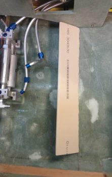
I started off with a bunch of small layups, thus the title of this blog post. First off, I sealed off the significant gap between the fresh air/heater air valve (Valve #1) plate and the duct sidewall. I taped off the valve plate with brown packing tape (I’m out of clear) and kept the valve plate up flush to what will be the back wall of the duct by taping it to a 12″ ruler that I laid across the other duct back wall edges as well.
I then added some flox along the edge of the taped up valve plate and added a ply of BID. I then peel plied it.
Since I used fast hardener in my epoxy, here’s a shot a few hours later when I pulled all the tape and cleaned it up. The top pic shows the valve in its normal closed state (fresh air through the ducts) while the bottom pic shows the valve open and the side edge seal at work (diverted air to heat exchanger).
When I created the valve plate edge seal above, I also laid up a ply of glass on the inside of the bottom horizontal duct edge and peel plied it. In addition, I cut a small rectangular reinforcement piece of 0.5mm aluminum and floxed in place on the outside bottom edge of the duct and covered it with 1 ply of BID. This too got peel plied.
These layups and aluminum plate will serve to reinforce the installation of the PIC/GIB air distribution valve (valve #3) when I install it.
Then, for the first time, I test mounted my Matco parking brake valve on and thru the finished & painted forward NG30 cover plate. Besides wanting to ensure the valve fit and clearance for the operation of the lever arm, I also needed it in place to determine the length of the parking brake control lever cable to the pull T-handle.
I played around with the control cable length for a while and estimated as closely as I could the final position of the parking brake pull T-handle. Once I decided on the parking brake T-handle location, I cut the entire cable to length, and then cut the outer cable sheath to expose the last 6″ or so of the control cable wire.
I then cut the 1/4″ Nylaflow control cable conduit and roughed it up with sandpaper. I also sanded all the contact point areas along the path of the 1/4″ Nylaflow conduit along the left side lower corner of the nose wheel well cover (NB) and along the bottom edge & side of the left NG30 plate.
I then 5-min glued about a 6″ length of the Nylaflow into place along the bottom corner of the nose wheel well cover (NB) and let it cure. After the 5-min glue cured, I then micro’d around the conduit and laid up a prepregged ply of BID 1.5″ wide x 9″ long.
I then peel plied the edges of the initial parking brake control cable conduit layup.
Since the path of the parking brake control cable conduit will require a sort of an “S” curve on the lower aft area of the left NG30 plate, I decided to secure & glass it in place in smaller, bite-sized sections in order to minimize my chances of any given section pulling free or going haywire as I set each segment in its correct spot.
I uploaded the above pics here side-by-side to give you somewhat of a panoramic view of the entire parking brake control cable run from T-handle to parking brake valve. Again, this is on the list of things needing done before I close up the top of the nose and access to these areas that I’m currently working is greatly restricted.
I have to say that there is often a lot of research, planning and design time spent that I don’t really report on. After I did all the above, I spent a good half hour assessing and reviewing the placement and configuration of the two pilot seat thigh support ribs. Moreover, I finalized the details on aft side of the pilot thigh support, which unlike most Long-EZs will be modified to incorporate a triangular duct across the aft edge for the right foot heater vent.
Tomorrow my next door neighbor is having a Labor Day cookout. Since I’ll be over at his place for most of the afternoon and evening, it will be yet another light build day. But I do plan on getting as much done as possible tomorrow on this internal cockpit stuff.
Today Chris Seats was going to come up from Fredericksburg, VA to pick up my extra canopy that he’s buying from me, and to take a look at my Long-EZ build. I finished up some errands and was about an hour into straightening up the shop when I got a message from him saying that traffic was way backed up and it was going to take him twice as long as usual to get here, so understandably Chris rescheduled his visit. If any of you know DC area traffic, it can be brutal at times.
So, I worked a bit more on getting my shop squared away when out of curiosity I checked the traffic situation from my side down. Interestingly, if I went down to see him it was going to taking half the time than him coming north. After conferring with Chris, I loaded up the Todd Silver made canopy and hauled it down to Chris’s shop in Fredericksburg.
I got there around 1530 and planned on leaving an hour or two later. Well, by the time I got out of there . . . of course talking all things Long-EZ, it was nearly 2100. I got some great ideas and some really good insight into some common engine components that we both have.
Obviously I didn’t get anything done on the build, except I do have a much cleaner and organized shop, but it was great to sit and chat with Chris regarding our respective builds.
As per usual, tomorrow I really plan to get back onto the build. Although I do have some more non-build related stuff scheduled that I need to get done.
I had planned for this past week to be a much more productive effort on the plane build, and while I did get some significant stuff done, it was not all build related.
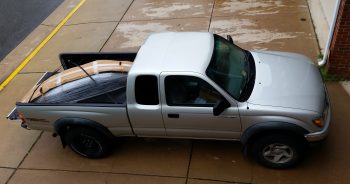
September is the month that I have to get an annual state mechanical safety inspection done on my truck. My truck has been limping along like a trooper as I’ve literally been soaking every mile out of these tires, going a few thousand miles over the oil change interval, etc. due primarily to my all-consuming focus on this build. Well, it was time to take a day or two to make my truck the pretty penny, so that it not only passes inspection, but lasts a few more years as well as I recover from this rather expensive plane build endeavor I’ve undertaken. That pretty much wiped out Wednesday & yesterday, but I was able to take the truck to the auto hobby shop on base and do an oil/filter change, new front brake pads, etc. Sunday will be new tires and that will be the lion’s share of my truck upkeep for a bit.
Today I had a whole list of shop build tasks to undertake, but that all went sideways with the myriad of phone calls I had –most plane build related– trying to nail down the purchase of some Bi-Lok reducer fittings for my hell hole brake line cross connects, and working with GRT on finalizing the purchase order on my GRT 8.4 HXr EFIS and EIS4000 engine management system. Both those efforts alone entailed a myriad of phone calls and some decisions I had to make on my side (read: a bit of research).
Since I had planned on hanging out with an old Air Force buddy of mine tonight, I knew it would be a short build day. So after talking with Jeff at GRT about their optional USB EFIS video input, I decided to explore that capability a bit more before heading out to dinner (i.e. no shop work).
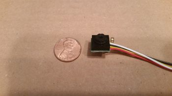
Quite a while ago I bought a very small video camera off Amazon for around $12 to test out. My specific idea was that with all the challenges I’ve heard from Long-EZ flyers about the real world ability of turning their head around and viewing the fuel site gauges in the back seat area, why not exploit GRT’s video input capability by using a couple of mini-video cameras to simply view the site gauge fuel levels (I do have Nick Ugolini’s fuel probes as well that feed the EFIS fuel tank quantities).
For an ounce or two tops in weight I can simply take a quick glance at a video feed in an inset on my EFIS and confirm the fuel site gauge level readings.
In addition, with a camera posted top CL of the pilot headrest looking aft, in one quick glance I can check the status of my top engine cowling and prop. Moreover, I can check the status of the GIB and make sure they’re doing ok.
Finally, since I found a 4-into-1 video feed unit online, I plan on attaching the fourth camera just aft of the front gear T-foot that hangs down in the airstream on the bottom CL of the fuselage. The camera will also be facing rearward to allow me to check on the health of the lower fuselage, landing brake, landing gear, lower cowling and prop. Since the air just aft of the nose gear T-foot will already be a bit turbulent, the mounted video camera’s tiny footprint shouldn’t increase drag by any significant degree.
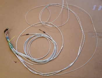
I figured out the wiring on the camera and dissected it a bit to see how I could use much thinner/lighter 24 AWG aircraft wiring to extend the leads vs using big, bulky, heavier audiovisual RCA jacks & cable leads to connect the cameras up to the avionics bay.
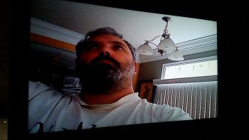
I of course wanted to see how well the video camera worked, so I connected it up to my dining room TV, added power to the tiny camera and Voila! As you can see the picture is definitely good enough to see any details required for my basic needs on the airplane.
With my nascent plan coming together for these incredibly light, tiny cameras, I can incorporate their installation into the build process as I move forward. There of course will be a bit of research and engineering to get exactly what I want as far as the control of what camera shows up on EFIS video feed, but beyond that I’m pretty much set.
Ok, another rabbit trail marked as recon’ed!
Tomorrow, Chris Seats will be coming over later in the afternoon to pick up my spare canopy that I threw up for sale on the canard group FaceBook page, and to check out my build progress. That means some requisite shop cleaning (yep, it’s still a mess!) and then after Chris leaves I’ll actually get back to building!
Today I started by doing another round of updates on my comm wiring diagram.
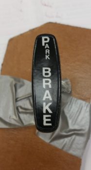
Then I started configuring the T-handle for the parking brake. Since I haven’t been able to find a properly labeled T-handle anywhere, my plan was to label it myself today and then clear coat so I could determine if I A) could do it, and B) needed any other materials to accomplish it.
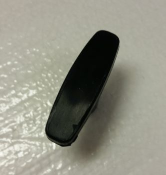
Here’s the type of handle that I used (it’s the same make, but a different handle than I actually used).
And here’s the same handle type after I labeled it with rub-on lettering. The letters weren’t perfect when I went to clear coat it, but moreover, some loose edges (unbeknownst to me at first) were literally blown away when I hit it with the initial application of clear coat. So, again, it’s clearly not perfect or as nice as it started out (or that I would prefer!), but it will definitely work as intended… at least for now.
As for the clear coat itself: I wanted to make sure that since this handle will most likely be subject to a fair amount of sunlight, and handled often, that the clear coat would stand up… so I shot 5 coats of matt clear on it.
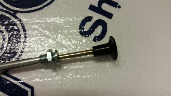
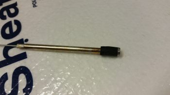
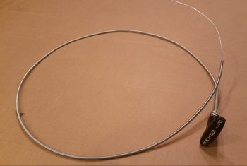
I then grabbed my comparatively lightweight cable assembly and handle –versus all the other T-handled cables I have on hand– and prepped it for trimming the handle down. I bought this cable assembly at an auto parts store a while back since it was so lightweight, but I wanted a T-handle that would allow both more (“easier”) gripping power & enough top surface area to label it.
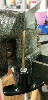
I grabbed my Dremel Tool and cut off the handle. After removing the plastic handle material, it was then that I discovered that inside the handle was basically a round bolt head.
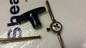
Originally I had planned on using the remaining plastic of the handle to secure the new handle in place with flox, but I then made the decision with the exposed round “bolt head” to cut as many 1/4-20 threads on it as I could to really help secure it in the new T-handle that I was going to mount.
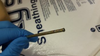
It was a bit tricky, but I was eventually able to use my die to cut a few 1/4-20 threads in the cable handle rod’s exposed round “bolt head” (yes, sorry for the pics!).
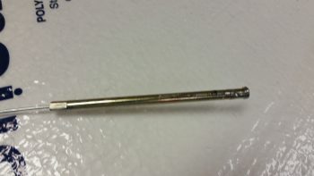
I then test mounted the freshly threaded cable handle rod and noted how deep the rod went into the handle. I then cut a couple grooves in the handle rod just below the threaded head to provide gripping for flox.
I then whipped up a small batch of epoxy with fast hardener, put a big drop of epoxy into the T-handle threads and threaded in the cable handle rod. With the rod set & clamped in place (hanging upside down), I then whipped up some wet flox to fill in the remaining void between the handle rod and the T-handle threads.
I then left the handle & cable assembly alone to cure.
Finally, here’s a pic of the parking brake handle floxed in place on the cable assembly, with the cable assembly installed in the cable assembly sheath. At this point the parking brake cable & handle assembly is ready for install. As for the weight, the entire assembly shown below weighs 4.55 oz. (0.29 lbs) whereas my stock T-handle cable from Aircraft Spruce weighs in at 13.85 oz. (0.87 lbs) . . . a whopping 67% heavier than the T-handle cable I just made.
As is often the case, I didn’t get nearly as much done as I had planned on today. But, getting this parking brake handle labeled somewhat successfully and installed on the cable assembly was a fairly big task that I can mark as completed. Again, it may seem that my timing is a little odd, but I need at least one T-handle assembly completed to determine both the correct placement for the handle and the required structure to build to house the parking brake and nose hatch release T-handles that will reside on each side of the nose gear wheel well viewing window. In addition, this housings for these two handles will bracket the fuel tank selector valve.
With this seemingly sideline task out of the way, tomorrow I can get back to working on the GIB fresh air & heating duct valve #3: the PIC & GIB air distribution valve.
Today I was still feeling pretty wiped out from my world wind trip down to North Carolina and Virginia Beach, so I took it kind of easy. As I was doing some domestic cleanup duties I ran across a book on Burt Rutan that my son gave me as a gift, so I spent a good hour or so reading that . . . a little inspiration for the build!
After reviewing a bunch of pics I took of Marco’s firewall and engine compartment, and researching a bit while looking at some other folks’ firewalls, I then reworked the component diagram I have for my firewall. May seem a bit ahead of the game, but if all goes right I will be mounting the firewall to the fuselage for good here in the next few weeks, and I wanted to figure out internal hell hole (aka “firewall forward”) cable & wiring runs, oil heat line configuration, and component placement. Obviously, figuring out a close estimate of where all my firewall transitions will be on the engine side of the firewall will drive the placement requirements on the hellhole side of the firewall.
In addition, as I install the canopy I will construct a GIB headrest assembly that will also be a compartment containing the GRT EIS4000 engine management control head and the Electroair Electronic Ignition controller as well. Having a good idea for where & how these component wires transit the firewall is a good thing.
Still in the electronics mode, and not feeling up to snuff for shop work, I worked a couple more connections on my Dynon Intercom wiring harness. Specifically, I prepped and terminated the 22AWG 2-conductor shielded cable for the Mic connection from the intercom to COM1 (GNS-480). Using the opposite end of the same 2-conductor cable, I also prepped & terminated the connection from the Intercom’s auxiliary audio input to the VX-Aviation AMX-2A 10-Channel Audio Mixer (see below). I also printed out & labeled these new Intercom wiring harness cables with heat shrink labels.
I’ve been kicking around the need for an audio mixer for a while now, but the reality of this requirement hit me as I was helping Marco with his panel upgrade on his flying Long-EZ. If there are more audio inputs coming into the Intercom from such devices that I have on hand like the Trio Autopilot, GNS-480 NAV & system audio outputs, etc. then an audio mixer is required to get them into one signal.
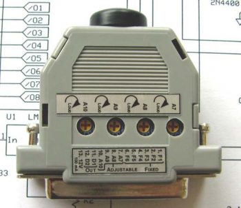
So, I finally made the decision to research out what I needed and make a final decision on what model would fit my requirements. The end result –which I’ve had my eye on for a while– was the VX-Aviation AMX-2A 10-Channel Audio Mixer. Apparently, Vern at VX-Avaition doesn’t sell these any more and has handed over sales control to makerplane.org, which is where the pic below is from.
As you can see, the form factor for this 10-channel audio mixer is a modified 25-pin D-Sub connector so the unit is very small and lightweight. I don’t need it just yet, but it is on my list of stuff to buy so I’ll most likely order one in the next month or few.
In addition, I finalized my decision on the AMX-2A by incorporating it into my Comms wiring diagram.
Tomorrow I plan on getting back into the shop and turning & burning to get the cockpit stuff knocked out to get on with finalizing the nose build and getting the canopy installed.
Today I started out by spending a couple of hours updating wiring system grounds and my comm component interconnections in some of my wiring diagrams. I also figured out my Audio Mixer requirement and updated that accordingly.
I then went down to the shop and spent a couple of hours cleaning and organizing it.
Then, since my next task required the dismantling of the mocked up heat exchanger and duct system, I decided to knock out the next oil heat system video that I had promised to do a while back . . . so here it is:
Tomorrow I’ll break down the oil heat & duct system and start working on it again. I’m not that far out from mounting it into the backseat area permanently.